US7892882B2 - Methods and apparatus for a semiconductor device package with improved thermal performance - Google Patents
Methods and apparatus for a semiconductor device package with improved thermal performanceDownload PDFInfo
- Publication number
- US7892882B2 US7892882B2US11/450,070US45007006AUS7892882B2US 7892882 B2US7892882 B2US 7892882B2US 45007006 AUS45007006 AUS 45007006AUS 7892882 B2US7892882 B2US 7892882B2
- Authority
- US
- United States
- Prior art keywords
- heat spreader
- semiconductor die
- adhesive material
- conductive
- providing
- Prior art date
- Legal status (The legal status is an assumption and is not a legal conclusion. Google has not performed a legal analysis and makes no representation as to the accuracy of the status listed.)
- Active, expires
Links
Images


Classifications
- H—ELECTRICITY
- H01—ELECTRIC ELEMENTS
- H01L—SEMICONDUCTOR DEVICES NOT COVERED BY CLASS H10
- H01L23/00—Details of semiconductor or other solid state devices
- H01L23/34—Arrangements for cooling, heating, ventilating or temperature compensation ; Temperature sensing arrangements
- H01L23/36—Selection of materials, or shaping, to facilitate cooling or heating, e.g. heatsinks
- H01L23/367—Cooling facilitated by shape of device
- H01L23/3677—Wire-like or pin-like cooling fins or heat sinks
- H—ELECTRICITY
- H01—ELECTRIC ELEMENTS
- H01L—SEMICONDUCTOR DEVICES NOT COVERED BY CLASS H10
- H01L24/00—Arrangements for connecting or disconnecting semiconductor or solid-state bodies; Methods or apparatus related thereto
- H01L24/01—Means for bonding being attached to, or being formed on, the surface to be connected, e.g. chip-to-package, die-attach, "first-level" interconnects; Manufacturing methods related thereto
- H01L24/18—High density interconnect [HDI] connectors; Manufacturing methods related thereto
- H01L24/23—Structure, shape, material or disposition of the high density interconnect connectors after the connecting process
- H01L24/24—Structure, shape, material or disposition of the high density interconnect connectors after the connecting process of an individual high density interconnect connector
- H—ELECTRICITY
- H01—ELECTRIC ELEMENTS
- H01L—SEMICONDUCTOR DEVICES NOT COVERED BY CLASS H10
- H01L24/00—Arrangements for connecting or disconnecting semiconductor or solid-state bodies; Methods or apparatus related thereto
- H01L24/01—Means for bonding being attached to, or being formed on, the surface to be connected, e.g. chip-to-package, die-attach, "first-level" interconnects; Manufacturing methods related thereto
- H01L24/26—Layer connectors, e.g. plate connectors, solder or adhesive layers; Manufacturing methods related thereto
- H01L24/31—Structure, shape, material or disposition of the layer connectors after the connecting process
- H01L24/32—Structure, shape, material or disposition of the layer connectors after the connecting process of an individual layer connector
- H—ELECTRICITY
- H01—ELECTRIC ELEMENTS
- H01L—SEMICONDUCTOR DEVICES NOT COVERED BY CLASS H10
- H01L24/00—Arrangements for connecting or disconnecting semiconductor or solid-state bodies; Methods or apparatus related thereto
- H01L24/73—Means for bonding being of different types provided for in two or more of groups H01L24/10, H01L24/18, H01L24/26, H01L24/34, H01L24/42, H01L24/50, H01L24/63, H01L24/71
- H—ELECTRICITY
- H01—ELECTRIC ELEMENTS
- H01L—SEMICONDUCTOR DEVICES NOT COVERED BY CLASS H10
- H01L24/00—Arrangements for connecting or disconnecting semiconductor or solid-state bodies; Methods or apparatus related thereto
- H01L24/80—Methods for connecting semiconductor or other solid state bodies using means for bonding being attached to, or being formed on, the surface to be connected
- H01L24/82—Methods for connecting semiconductor or other solid state bodies using means for bonding being attached to, or being formed on, the surface to be connected by forming build-up interconnects at chip-level, e.g. for high density interconnects [HDI]
- H—ELECTRICITY
- H01—ELECTRIC ELEMENTS
- H01L—SEMICONDUCTOR DEVICES NOT COVERED BY CLASS H10
- H01L24/00—Arrangements for connecting or disconnecting semiconductor or solid-state bodies; Methods or apparatus related thereto
- H01L24/80—Methods for connecting semiconductor or other solid state bodies using means for bonding being attached to, or being formed on, the surface to be connected
- H01L24/83—Methods for connecting semiconductor or other solid state bodies using means for bonding being attached to, or being formed on, the surface to be connected using a layer connector
- H—ELECTRICITY
- H01—ELECTRIC ELEMENTS
- H01L—SEMICONDUCTOR DEVICES NOT COVERED BY CLASS H10
- H01L21/00—Processes or apparatus adapted for the manufacture or treatment of semiconductor or solid state devices or of parts thereof
- H01L21/02—Manufacture or treatment of semiconductor devices or of parts thereof
- H01L21/04—Manufacture or treatment of semiconductor devices or of parts thereof the devices having potential barriers, e.g. a PN junction, depletion layer or carrier concentration layer
- H01L21/50—Assembly of semiconductor devices using processes or apparatus not provided for in a single one of the groups H01L21/18 - H01L21/326 or H10D48/04 - H10D48/07 e.g. sealing of a cap to a base of a container
- H01L21/56—Encapsulations, e.g. encapsulation layers, coatings
- H01L21/568—Temporary substrate used as encapsulation process aid
- H—ELECTRICITY
- H01—ELECTRIC ELEMENTS
- H01L—SEMICONDUCTOR DEVICES NOT COVERED BY CLASS H10
- H01L2224/00—Indexing scheme for arrangements for connecting or disconnecting semiconductor or solid-state bodies and methods related thereto as covered by H01L24/00
- H01L2224/01—Means for bonding being attached to, or being formed on, the surface to be connected, e.g. chip-to-package, die-attach, "first-level" interconnects; Manufacturing methods related thereto
- H01L2224/02—Bonding areas; Manufacturing methods related thereto
- H01L2224/04—Structure, shape, material or disposition of the bonding areas prior to the connecting process
- H01L2224/04105—Bonding areas formed on an encapsulation of the semiconductor or solid-state body, e.g. bonding areas on chip-scale packages
- H—ELECTRICITY
- H01—ELECTRIC ELEMENTS
- H01L—SEMICONDUCTOR DEVICES NOT COVERED BY CLASS H10
- H01L2224/00—Indexing scheme for arrangements for connecting or disconnecting semiconductor or solid-state bodies and methods related thereto as covered by H01L24/00
- H01L2224/01—Means for bonding being attached to, or being formed on, the surface to be connected, e.g. chip-to-package, die-attach, "first-level" interconnects; Manufacturing methods related thereto
- H01L2224/18—High density interconnect [HDI] connectors; Manufacturing methods related thereto
- H01L2224/23—Structure, shape, material or disposition of the high density interconnect connectors after the connecting process
- H01L2224/24—Structure, shape, material or disposition of the high density interconnect connectors after the connecting process of an individual high density interconnect connector
- H01L2224/241—Disposition
- H01L2224/24151—Connecting between a semiconductor or solid-state body and an item not being a semiconductor or solid-state body, e.g. chip-to-substrate, chip-to-passive
- H01L2224/24221—Connecting between a semiconductor or solid-state body and an item not being a semiconductor or solid-state body, e.g. chip-to-substrate, chip-to-passive the body and the item being stacked
- H01L2224/24225—Connecting between a semiconductor or solid-state body and an item not being a semiconductor or solid-state body, e.g. chip-to-substrate, chip-to-passive the body and the item being stacked the item being non-metallic, e.g. insulating substrate with or without metallisation
- H01L2224/24227—Connecting between a semiconductor or solid-state body and an item not being a semiconductor or solid-state body, e.g. chip-to-substrate, chip-to-passive the body and the item being stacked the item being non-metallic, e.g. insulating substrate with or without metallisation the HDI interconnect not connecting to the same level of the item at which the semiconductor or solid-state body is mounted, e.g. the semiconductor or solid-state body being mounted in a cavity or on a protrusion of the item
- H—ELECTRICITY
- H01—ELECTRIC ELEMENTS
- H01L—SEMICONDUCTOR DEVICES NOT COVERED BY CLASS H10
- H01L2224/00—Indexing scheme for arrangements for connecting or disconnecting semiconductor or solid-state bodies and methods related thereto as covered by H01L24/00
- H01L2224/01—Means for bonding being attached to, or being formed on, the surface to be connected, e.g. chip-to-package, die-attach, "first-level" interconnects; Manufacturing methods related thereto
- H01L2224/26—Layer connectors, e.g. plate connectors, solder or adhesive layers; Manufacturing methods related thereto
- H01L2224/28—Structure, shape, material or disposition of the layer connectors prior to the connecting process
- H01L2224/29—Structure, shape, material or disposition of the layer connectors prior to the connecting process of an individual layer connector
- H01L2224/29001—Core members of the layer connector
- H01L2224/29099—Material
- H01L2224/2919—Material with a principal constituent of the material being a polymer, e.g. polyester, phenolic based polymer, epoxy
- H—ELECTRICITY
- H01—ELECTRIC ELEMENTS
- H01L—SEMICONDUCTOR DEVICES NOT COVERED BY CLASS H10
- H01L2224/00—Indexing scheme for arrangements for connecting or disconnecting semiconductor or solid-state bodies and methods related thereto as covered by H01L24/00
- H01L2224/01—Means for bonding being attached to, or being formed on, the surface to be connected, e.g. chip-to-package, die-attach, "first-level" interconnects; Manufacturing methods related thereto
- H01L2224/26—Layer connectors, e.g. plate connectors, solder or adhesive layers; Manufacturing methods related thereto
- H01L2224/31—Structure, shape, material or disposition of the layer connectors after the connecting process
- H01L2224/32—Structure, shape, material or disposition of the layer connectors after the connecting process of an individual layer connector
- H01L2224/3205—Shape
- H01L2224/32057—Shape in side view
- H—ELECTRICITY
- H01—ELECTRIC ELEMENTS
- H01L—SEMICONDUCTOR DEVICES NOT COVERED BY CLASS H10
- H01L2224/00—Indexing scheme for arrangements for connecting or disconnecting semiconductor or solid-state bodies and methods related thereto as covered by H01L24/00
- H01L2224/01—Means for bonding being attached to, or being formed on, the surface to be connected, e.g. chip-to-package, die-attach, "first-level" interconnects; Manufacturing methods related thereto
- H01L2224/42—Wire connectors; Manufacturing methods related thereto
- H01L2224/47—Structure, shape, material or disposition of the wire connectors after the connecting process
- H01L2224/48—Structure, shape, material or disposition of the wire connectors after the connecting process of an individual wire connector
- H01L2224/4805—Shape
- H01L2224/4809—Loop shape
- H01L2224/48091—Arched
- H—ELECTRICITY
- H01—ELECTRIC ELEMENTS
- H01L—SEMICONDUCTOR DEVICES NOT COVERED BY CLASS H10
- H01L2224/00—Indexing scheme for arrangements for connecting or disconnecting semiconductor or solid-state bodies and methods related thereto as covered by H01L24/00
- H01L2224/01—Means for bonding being attached to, or being formed on, the surface to be connected, e.g. chip-to-package, die-attach, "first-level" interconnects; Manufacturing methods related thereto
- H01L2224/42—Wire connectors; Manufacturing methods related thereto
- H01L2224/47—Structure, shape, material or disposition of the wire connectors after the connecting process
- H01L2224/48—Structure, shape, material or disposition of the wire connectors after the connecting process of an individual wire connector
- H01L2224/481—Disposition
- H01L2224/48151—Connecting between a semiconductor or solid-state body and an item not being a semiconductor or solid-state body, e.g. chip-to-substrate, chip-to-passive
- H01L2224/48221—Connecting between a semiconductor or solid-state body and an item not being a semiconductor or solid-state body, e.g. chip-to-substrate, chip-to-passive the body and the item being stacked
- H01L2224/48225—Connecting between a semiconductor or solid-state body and an item not being a semiconductor or solid-state body, e.g. chip-to-substrate, chip-to-passive the body and the item being stacked the item being non-metallic, e.g. insulating substrate with or without metallisation
- H01L2224/48227—Connecting between a semiconductor or solid-state body and an item not being a semiconductor or solid-state body, e.g. chip-to-substrate, chip-to-passive the body and the item being stacked the item being non-metallic, e.g. insulating substrate with or without metallisation connecting the wire to a bond pad of the item
- H—ELECTRICITY
- H01—ELECTRIC ELEMENTS
- H01L—SEMICONDUCTOR DEVICES NOT COVERED BY CLASS H10
- H01L2224/00—Indexing scheme for arrangements for connecting or disconnecting semiconductor or solid-state bodies and methods related thereto as covered by H01L24/00
- H01L2224/73—Means for bonding being of different types provided for in two or more of groups H01L2224/10, H01L2224/18, H01L2224/26, H01L2224/34, H01L2224/42, H01L2224/50, H01L2224/63, H01L2224/71
- H01L2224/732—Location after the connecting process
- H01L2224/73251—Location after the connecting process on different surfaces
- H01L2224/73267—Layer and HDI connectors
- H—ELECTRICITY
- H01—ELECTRIC ELEMENTS
- H01L—SEMICONDUCTOR DEVICES NOT COVERED BY CLASS H10
- H01L2224/00—Indexing scheme for arrangements for connecting or disconnecting semiconductor or solid-state bodies and methods related thereto as covered by H01L24/00
- H01L2224/80—Methods for connecting semiconductor or other solid state bodies using means for bonding being attached to, or being formed on, the surface to be connected
- H01L2224/83—Methods for connecting semiconductor or other solid state bodies using means for bonding being attached to, or being formed on, the surface to be connected using a layer connector
- H01L2224/8319—Arrangement of the layer connectors prior to mounting
- H01L2224/83191—Arrangement of the layer connectors prior to mounting wherein the layer connectors are disposed only on the semiconductor or solid-state body
- H—ELECTRICITY
- H01—ELECTRIC ELEMENTS
- H01L—SEMICONDUCTOR DEVICES NOT COVERED BY CLASS H10
- H01L2224/00—Indexing scheme for arrangements for connecting or disconnecting semiconductor or solid-state bodies and methods related thereto as covered by H01L24/00
- H01L2224/80—Methods for connecting semiconductor or other solid state bodies using means for bonding being attached to, or being formed on, the surface to be connected
- H01L2224/83—Methods for connecting semiconductor or other solid state bodies using means for bonding being attached to, or being formed on, the surface to be connected using a layer connector
- H01L2224/8338—Bonding interfaces outside the semiconductor or solid-state body
- H01L2224/83385—Shape, e.g. interlocking features
- H—ELECTRICITY
- H01—ELECTRIC ELEMENTS
- H01L—SEMICONDUCTOR DEVICES NOT COVERED BY CLASS H10
- H01L2224/00—Indexing scheme for arrangements for connecting or disconnecting semiconductor or solid-state bodies and methods related thereto as covered by H01L24/00
- H01L2224/80—Methods for connecting semiconductor or other solid state bodies using means for bonding being attached to, or being formed on, the surface to be connected
- H01L2224/83—Methods for connecting semiconductor or other solid state bodies using means for bonding being attached to, or being formed on, the surface to be connected using a layer connector
- H01L2224/838—Bonding techniques
- H—ELECTRICITY
- H01—ELECTRIC ELEMENTS
- H01L—SEMICONDUCTOR DEVICES NOT COVERED BY CLASS H10
- H01L2224/00—Indexing scheme for arrangements for connecting or disconnecting semiconductor or solid-state bodies and methods related thereto as covered by H01L24/00
- H01L2224/91—Methods for connecting semiconductor or solid state bodies including different methods provided for in two or more of groups H01L2224/80 - H01L2224/90
- H01L2224/92—Specific sequence of method steps
- H01L2224/922—Connecting different surfaces of the semiconductor or solid-state body with connectors of different types
- H01L2224/9222—Sequential connecting processes
- H01L2224/92242—Sequential connecting processes the first connecting process involving a layer connector
- H01L2224/92244—Sequential connecting processes the first connecting process involving a layer connector the second connecting process involving a build-up interconnect
- H—ELECTRICITY
- H01—ELECTRIC ELEMENTS
- H01L—SEMICONDUCTOR DEVICES NOT COVERED BY CLASS H10
- H01L24/00—Arrangements for connecting or disconnecting semiconductor or solid-state bodies; Methods or apparatus related thereto
- H01L24/01—Means for bonding being attached to, or being formed on, the surface to be connected, e.g. chip-to-package, die-attach, "first-level" interconnects; Manufacturing methods related thereto
- H01L24/42—Wire connectors; Manufacturing methods related thereto
- H01L24/47—Structure, shape, material or disposition of the wire connectors after the connecting process
- H01L24/48—Structure, shape, material or disposition of the wire connectors after the connecting process of an individual wire connector
- H—ELECTRICITY
- H01—ELECTRIC ELEMENTS
- H01L—SEMICONDUCTOR DEVICES NOT COVERED BY CLASS H10
- H01L2924/00—Indexing scheme for arrangements or methods for connecting or disconnecting semiconductor or solid-state bodies as covered by H01L24/00
- H01L2924/0001—Technical content checked by a classifier
- H01L2924/00014—Technical content checked by a classifier the subject-matter covered by the group, the symbol of which is combined with the symbol of this group, being disclosed without further technical details
- H—ELECTRICITY
- H01—ELECTRIC ELEMENTS
- H01L—SEMICONDUCTOR DEVICES NOT COVERED BY CLASS H10
- H01L2924/00—Indexing scheme for arrangements or methods for connecting or disconnecting semiconductor or solid-state bodies as covered by H01L24/00
- H01L2924/01—Chemical elements
- H01L2924/01006—Carbon [C]
- H—ELECTRICITY
- H01—ELECTRIC ELEMENTS
- H01L—SEMICONDUCTOR DEVICES NOT COVERED BY CLASS H10
- H01L2924/00—Indexing scheme for arrangements or methods for connecting or disconnecting semiconductor or solid-state bodies as covered by H01L24/00
- H01L2924/01—Chemical elements
- H01L2924/01013—Aluminum [Al]
- H—ELECTRICITY
- H01—ELECTRIC ELEMENTS
- H01L—SEMICONDUCTOR DEVICES NOT COVERED BY CLASS H10
- H01L2924/00—Indexing scheme for arrangements or methods for connecting or disconnecting semiconductor or solid-state bodies as covered by H01L24/00
- H01L2924/01—Chemical elements
- H01L2924/01029—Copper [Cu]
- H—ELECTRICITY
- H01—ELECTRIC ELEMENTS
- H01L—SEMICONDUCTOR DEVICES NOT COVERED BY CLASS H10
- H01L2924/00—Indexing scheme for arrangements or methods for connecting or disconnecting semiconductor or solid-state bodies as covered by H01L24/00
- H01L2924/01—Chemical elements
- H01L2924/01033—Arsenic [As]
- H—ELECTRICITY
- H01—ELECTRIC ELEMENTS
- H01L—SEMICONDUCTOR DEVICES NOT COVERED BY CLASS H10
- H01L2924/00—Indexing scheme for arrangements or methods for connecting or disconnecting semiconductor or solid-state bodies as covered by H01L24/00
- H01L2924/01—Chemical elements
- H01L2924/01047—Silver [Ag]
- H—ELECTRICITY
- H01—ELECTRIC ELEMENTS
- H01L—SEMICONDUCTOR DEVICES NOT COVERED BY CLASS H10
- H01L2924/00—Indexing scheme for arrangements or methods for connecting or disconnecting semiconductor or solid-state bodies as covered by H01L24/00
- H01L2924/01—Chemical elements
- H01L2924/01074—Tungsten [W]
- H—ELECTRICITY
- H01—ELECTRIC ELEMENTS
- H01L—SEMICONDUCTOR DEVICES NOT COVERED BY CLASS H10
- H01L2924/00—Indexing scheme for arrangements or methods for connecting or disconnecting semiconductor or solid-state bodies as covered by H01L24/00
- H01L2924/01—Chemical elements
- H01L2924/01082—Lead [Pb]
- H—ELECTRICITY
- H01—ELECTRIC ELEMENTS
- H01L—SEMICONDUCTOR DEVICES NOT COVERED BY CLASS H10
- H01L2924/00—Indexing scheme for arrangements or methods for connecting or disconnecting semiconductor or solid-state bodies as covered by H01L24/00
- H01L2924/013—Alloys
- H01L2924/014—Solder alloys
- H—ELECTRICITY
- H01—ELECTRIC ELEMENTS
- H01L—SEMICONDUCTOR DEVICES NOT COVERED BY CLASS H10
- H01L2924/00—Indexing scheme for arrangements or methods for connecting or disconnecting semiconductor or solid-state bodies as covered by H01L24/00
- H01L2924/06—Polymers
- H01L2924/0665—Epoxy resin
- H—ELECTRICITY
- H01—ELECTRIC ELEMENTS
- H01L—SEMICONDUCTOR DEVICES NOT COVERED BY CLASS H10
- H01L2924/00—Indexing scheme for arrangements or methods for connecting or disconnecting semiconductor or solid-state bodies as covered by H01L24/00
- H01L2924/10—Details of semiconductor or other solid state devices to be connected
- H01L2924/102—Material of the semiconductor or solid state bodies
- H01L2924/1025—Semiconducting materials
- H01L2924/10251—Elemental semiconductors, i.e. Group IV
- H01L2924/10253—Silicon [Si]
- H—ELECTRICITY
- H01—ELECTRIC ELEMENTS
- H01L—SEMICONDUCTOR DEVICES NOT COVERED BY CLASS H10
- H01L2924/00—Indexing scheme for arrangements or methods for connecting or disconnecting semiconductor or solid-state bodies as covered by H01L24/00
- H01L2924/10—Details of semiconductor or other solid state devices to be connected
- H01L2924/11—Device type
- H01L2924/14—Integrated circuits
- H—ELECTRICITY
- H01—ELECTRIC ELEMENTS
- H01L—SEMICONDUCTOR DEVICES NOT COVERED BY CLASS H10
- H01L2924/00—Indexing scheme for arrangements or methods for connecting or disconnecting semiconductor or solid-state bodies as covered by H01L24/00
- H01L2924/15—Details of package parts other than the semiconductor or other solid state devices to be connected
- H01L2924/151—Die mounting substrate
- H01L2924/1515—Shape
- H01L2924/15153—Shape the die mounting substrate comprising a recess for hosting the device
- H—ELECTRICITY
- H01—ELECTRIC ELEMENTS
- H01L—SEMICONDUCTOR DEVICES NOT COVERED BY CLASS H10
- H01L2924/00—Indexing scheme for arrangements or methods for connecting or disconnecting semiconductor or solid-state bodies as covered by H01L24/00
- H01L2924/15—Details of package parts other than the semiconductor or other solid state devices to be connected
- H01L2924/151—Die mounting substrate
- H01L2924/156—Material
- H01L2924/157—Material with a principal constituent of the material being a metal or a metalloid, e.g. boron [B], silicon [Si], germanium [Ge], arsenic [As], antimony [Sb], tellurium [Te] and polonium [Po], and alloys thereof
- H01L2924/15738—Material with a principal constituent of the material being a metal or a metalloid, e.g. boron [B], silicon [Si], germanium [Ge], arsenic [As], antimony [Sb], tellurium [Te] and polonium [Po], and alloys thereof the principal constituent melting at a temperature of greater than or equal to 950 C and less than 1550 C
- H01L2924/15747—Copper [Cu] as principal constituent
- H—ELECTRICITY
- H01—ELECTRIC ELEMENTS
- H01L—SEMICONDUCTOR DEVICES NOT COVERED BY CLASS H10
- H01L2924/00—Indexing scheme for arrangements or methods for connecting or disconnecting semiconductor or solid-state bodies as covered by H01L24/00
- H01L2924/15—Details of package parts other than the semiconductor or other solid state devices to be connected
- H01L2924/181—Encapsulation
Definitions
- the present inventionrelates generally to electronic package assemblies, and more particularly, to leadframe designs for power amplifier dies in wafer-level, embedded chip package assemblies.
- Radio frequency (RF) power amplifier componentsare typically relatively small, but dissipate large amounts of heat during operation.
- Embedded die package techniqueswherein the die's active side faces downward with respect to the build-up circuits—do not lend themselves well to managing thermal output due to the limitation in the number of thermal vias that can contact the active face of the die, and because backside contact is not always provided.
- the die junction temperature in such packaging schemesmay exceed the limit of 150° C. during operation.
- power amplifier devicestypically incorporate backside contact for grounding purposes.
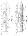
- FIG. 1is a cross-sectional overview of a typical prior art electronic package assembly
- FIG. 2is a cross-sectional overview of an electronic package assembly in accordance with one exemplary embodiment
- FIG. 3is a cross-sectional overview of another exemplary embodiment of an electronic package assembly
- FIG. 4is a cross-sectional overview of yet another exemplary embodiment of an electronic package assembly
- FIG. 5is a cross-sectional overview of one step of an exemplary embodiment of a process to produce the electronic package assembly of FIG. 2 ;
- FIG. 6is a cross-sectional overview of another step in the process of FIG. 5 ;
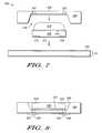
- FIG. 7is a cross-sectional overview of one step of an exemplary embodiment of a process to produce the electronic package assembly of FIG. 3 ;
- FIG. 8is a cross-sectional overview of another step in the process of FIG. 7 ;
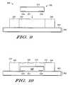
- FIG. 9is a cross-sectional overview of one step of an exemplary embodiment of another process to produce the electronic package assembly of FIG. 3 ;
- FIG. 10is a cross-sectional overview of another step of the process of FIG. 9 ;
- FIG. 11is a diagram of one step of an exemplary embodiment of a process to produce the electronic package assembly of FIG. 4 ;
- FIG. 12is a cross-sectional overview of another step of the process of FIG. 11 ;
- FIG. 13is a diagram of yet another step of the process of FIG. 12 ;
- FIG. 14is a diagram of an alternative embodiment of an electronic package assembly manufactured according to the processes discussed in FIGS. 11-13 .
- a conventional electronic package assembly 100includes a semiconductor die 108 incorporating one or more active terminal bond pad contacts 118 , wherein a backside 119 of semiconductor die 108 is surrounded by an encapsulant 106 . Furthermore, semiconductor die 108 is in contact with a build-up circuit 102 , wherein build-up circuit 102 includes one or more layers 110 incorporating various electrical vias 112 , thermal vias 113 , contact pads 114 , and the like. Such baseband integrated circuits, transceivers, power management modules, and the like may be used in an integrated radio application.
- Encapsulant 106is typically an epoxy or other polymeric material, and may include various glass and/or plastic filler materials. As a result, its thermal conductivity is relatively low, and thus does not provide an effective heat conduction path to the environment. Generated heat is therefore primarily dissipated away from semiconductor die 108 via heat paths 116 . Generally, heat paths 116 that are provided by thermal vias 113 are not, by themselves, capable of dissipating the entire amount of heat generated by semiconductor die 108 when semiconductor die 108 is, for example, a power amplifier.
- FIG. 2depicts an electronic package assembly 200 in accordance with one embodiment of the present invention.
- Electronic package assembly 200includes a semiconductor die 208 (e.g., an RF power amplifier or other such device) having one or more active terminal bond pad contacts 218 formed on and/or within die 208 .
- Die 208is fixed within a cavity (shown in FIG. 5 as reference numeral 210 ) of a conductive leadframe or heat spreader 204 (hereinafter conductive leadframe) using a thermally and/or electrically conductive adhesive material 209 .
- Conductive leadframe 204includes two substantially planar surfaces on opposite sides of cavity 210 .
- Conductive leadframe 204functions, in accordance with one aspect, as a heat spreader (assisting in lateral conduction of heat energy), and thus may be referred to herein alternatively as a “heat spreader.”
- Conductive leadframe 204may be formed of any material suitable for conducting heat and/or electricity (e.g., aluminum, ceramic, a metal, an alloy, or other similar thermally and/or electrically conductive material). In accordance with one embodiment, for example, conductive leadframe 204 is formed of copper or a copper alloy.
- conductive leadframe 204may be selected to achieve any desired design objectives, and therefore may vary in dimensions depending upon, among other things, the dimensions and steady-state heat dissipation of die 208 .
- conductive leadframe 204is at least 1.5 times larger in area (viewed from a plan view) than semiconductor die 208 .
- conductive leadframe 204is in the range of about 1.5 times to about 5.0 times larger than semiconductor die 208 . It will be appreciated, however, that the invention is not so limited.
- Adhesive material 209suitably connects semiconductor die 208 to conductive leadframe 204 such that a front side 221 (i.e., the active side) of semiconductor die 208 is substantially coplanar with front sides 205 of conductive leadframe 204 . Furthermore, a backside 219 (i.e., the side including a conductive contact) is electrically and/or thermally coupled to conductive leadframe 204 .
- the exposed active area of semiconductor die 208may be processed with a build-up circuit 202 (e.g., a surface including electrical vias 212 , thermal vias 213 , other thermal management components, and/or contact pads 214 ) while at the same time providing an electrical connection 220 (e.g., a ground connection) to back side 219 .
- a build-up circuit 202e.g., a surface including electrical vias 212 , thermal vias 213 , other thermal management components, and/or contact pads 214
- an electrical connection 220e.g., a ground connection
- adhesive material 209may be any material or combination of materials capable of bonding semiconductor die 208 to conductive leadframe 204 , and capable of conducting heat away from die 208 and, optionally, providing an electrical path to backside 219 of die 208 .
- adhesive material 209is a silver-filled epoxy.
- adhesive material 209is conventional solder material.
- thermally-conductiveas used herein with reference to a material means that the material has a thermal conductivity greater than that of the surrounding encapsulant 206 .
- encapsulant 206is a conventional silica-filled epoxy resin with a thermal conductivity ranging from about 0.5-1.0 W/mK, and adhesive material 209 has a thermal conductivity greater than 1.0 W/mK, preferably about 2.0 W/mK or greater.
- Conductive leadframe 204 , adhesive material 209 , and semiconductor die 208are fixed in place by encapsulant 206 , which is similar to encapsulant 106 discussed above with reference to FIG. 1 . As such, heat is dissipated from semiconductor die 208 via heat paths 215 and heat paths 217 , in addition to heat paths 216 , during operation of electronic package assembly 200 .
- FIG. 3is a diagram of an embodiment of an electronic package assembly 300 .
- Electronic package assembly 300includes a semiconductor die 308 having active terminal bond pad contacts 318 positioned within a conductive leadframe 304 using a thermally and/or electrically conductive adhesive material 309 , wherein semiconductor 308 is similar to semiconductor die 208 , conductive leadframe 304 is similar to conductive leadframe 204 , and adhesive material 309 is similar to conductive adhesive material 209 .
- Adhesive material 309connects semiconductor die 308 to conductive leadframe 304 such that a front side 321 (i.e., the active side) of semiconductor die 308 is substantially coplanar with front sides 305 . Furthermore, a back side 319 (i.e., the side including a conductive contact) of semiconductor die 308 is electrically and/or thermally connected to conductive leadframe 304 .
- the exposed active area of semiconductor die 308may be further processed with a build-up circuit 302 (which includes electrical vias 311 , thermal vias 313 or other thermal management components, and/or contact pads 314 while at the same time providing an electrical connection 320 (e.g., a ground connection) to back side 319 .
- a build-up circuit 302which includes electrical vias 311 , thermal vias 313 or other thermal management components, and/or contact pads 314 while at the same time providing an electrical connection 320 (e.g., a ground connection) to back side 319 .
- conductive leadframe 304is collectively at least 1.5 times larger in area than semiconductor die 308 . In another exemplary embodiment, conductive leadframe 304 is collectively in the range of about 1.5 times to about 5.0 times larger in overall planar area than semiconductor die 308 .
- semiconductor die 308 , conductive leadframe 304 , and adhesive material 309are surrounded by an encapsulant 306 using means known in the art, wherein encapsulant 306 is similar to encapsulant 106 discussed above.
- heatis dissipated from semiconductor die 308 via heat paths 317 , in addition to heat paths 316 , during operation of electronic package assembly 300 .
- FIG. 4is a diagram of one embodiment of an electronic package assembly 400 .
- Electronic package assembly 400includes a semiconductor die 408 having active terminal bond pad contacts 418 fixed between a conductive leadframe 404 using a thermally and/or electrically conductive adhesive material 409 , similar to semiconductor die 308 , conductive leadframe 304 , and adhesive material 309 , respectively.
- adhesive material 409connects semiconductor die 408 to conductive leadframe 404 such that a front side 421 (i.e., the active side) of semiconductor die 408 is substantially coplanar with front sides 405 of conductive leadframe 404 . Furthermore, a back side 419 (i.e., the side including a conductive contact) is electrically and/or thermally coupled to conductive leadframe 404 . In this way, the exposed active area of semiconductor die 408 , with a ready-to-mount package, may be further processed with a build-up circuit 402 (which includes electrical vias 423 , thermal vias 413 , other thermal management components, and/or contact pads 414 ) while at the same time providing an electrical connection 420 to back side 419 .
- a build-up circuit 402which includes electrical vias 423 , thermal vias 413 , other thermal management components, and/or contact pads 414 .
- semiconductor die 408 and conductive leadframe 404are connected to a lid 411 using adhesive material 409 .
- lid 411includes one or more vents 407 through it such that adhesive material 409 flows through vents 407 during, for example, manufacturing.
- conductive leadframe 404 , and lid 411are collectively at least 1.5 times larger in area than semiconductor die 408 . In another exemplary embodiment, conductive leadframe 404 , and lid 411 are collectively in the range of about 1.5 times to about 5.0 times larger in overall planar area than semiconductor die 408 .
- an encapsulant 406is connected to lid 411 and conductive leadframe 404 using adhesive material 409 , wherein encapsulant 406 is similar to encapsulant 106 discussed above. As such, heat is dissipated from semiconductor die 408 via heat paths 415 and heat paths 417 , in addition to heat paths 416 , during operation of electronic package assembly 400 .
- conductive leadframe 404may be of varying thickness and back side 419 is left exposed to enable the adaptation of a heat spreader (e.g., lid 411 ) as a post assembly process.
- encapsulant 406encapsulates conductive leadframe 404 up to both edges of semiconductor die 408 leaving a cavity over back side 419 .
- the cavitymay include any dimensions and/or shape consistent with the dimensions of semiconductor die 408 .
- back side 419does not necessarily need to be planar with the top surface of electronic package assembly 400 .
- adhesive material 409 or a similarly dispensed adhesive material or film adhesivecan be utilized to attach the heat dissipating device to back side 419 .
- FIG. 5is a diagram of one step of an exemplary embodiment of a process 500 to produce electronic package assembly 200 .
- Process 500initiates by providing a tooling fixture 501 .
- conductive leadframe 204is placed on planar construction base 501 and a controlled amount of adhesive material 209 is dispensed within a cavity 210 of conductive leadframe 204 .
- semiconductor die 208is then placed on adhesive material 209 in cavity 210 so that back side 219 comes into contact with adhesive material 209 .
- the amount of adhesive material 209should be an amount such that, when cured, adhesive material 209 is coplanar or substantially coplanar with front side 221 . Moreover, it is important to ensure that adhesive material 209 does not come into contact with front side 221 or with active terminal bond pad contacts 218 during process 500 .
- encapsulant 206(not shown) is appropriately connected to leadframe 204 , and electronic package assembly 200 is removed from tooling fixture 501 .
- FIGS. 5 and 6have been discussed with respect to a single electronic package assembly 200 , one skilled in the art will appreciate that during process 500 multiple electronic package assemblies 200 may be produced. As such, process 500 is not limited to producing a single electronic package assembly 200 .
- FIGS. 5 and 6have been discussed with respect to a two layer metallization build-up process, one skilled in the art knows that during process 500 more than two layers may be produced. As such, process 500 is not limited to producing a specific number of layers.
- FIGS. 5 and 6discuss utilizing adhesive material 209 , one skilled in the art would recognize that a thermally conductive film adhesive could also be utilized. In such case, conductive leadframe 204 does not require any particular shape or vents, and may result in a thinner and easier package to manufacture.
- FIG. 7is a diagram of one step of an exemplary embodiment of a process 700 to produce electronic package assembly 300 .
- Process 700initiates by providing a planar construction base 701 (e.g., a silicon wafer) on which a temporary tape 703 is placed.
- a planar construction base 701e.g., a silicon wafer
- front side 321including active terminal bond pad contacts 318
- semiconductor die 308is placed upon temporary tape 703 .
- a controlled amount of adhesive material 309is then dispensed on back side 319 .
- Leadframe 304is then placed over semiconductor die 308 and adhesive material 309 such that semiconductor die 308 and adhesive material 309 fit within a cavity 310 of conductive leadframe 304 .
- FIG. 8shows electronic package assembly 300 after the respective portions have been connected to one another.
- conductive leadframe 304includes a portion 330 having vents 307 such that adhesive material 309 substantially fills cavity 310 and vents 307 .
- excessive adhesive material 309 that protrudes outside vents 307 to an external surface of conductive leadframe 304is removed from electronic package assembly 300 using, for example, a grinding technique.
- Encapsulant 306(not shown) is then appropriately connected to leadframe 304 , and electronic package assembly 300 is removed from temporary tape 703 .
- FIGS. 7 and 8have been discussed with respect to a single electronic package assembly 300 , one skilled in the art knows that during process 700 multiple electronic package assemblies 300 may be produced. As such, process 700 is not limited to producing a single electronic package assembly 300 .
- FIGS. 7 and 8have been discussed with respect to a two layer metallization build-up process, one skilled in the art knows that during process 700 more than two layers may be produced. As such, process 700 is not limited to producing a specific number of layers.
- FIG. 9is a diagram of one step of exemplary embodiment of another process 900 to produce electronic package assembly 300 .
- Process 900initiates by providing a planar construction base 901 (e.g., a silicon wafer), whereupon which a temporary tape 903 is placed.
- leadframe 304is placed upon temporary tape 903 with cavity 310 configured as shown.
- Semiconductor die 308is placed within cavity 310 with front side 321 (which includes active terminal bond pad contacts 318 ) contacting temporary tape 903 and back side 319 is oriented upward.
- a controlled amount of adhesive material 309is then dispensed within cavity 310 such that adhesive material 309 is coplanar with or substantially coplanar with an upper surface 312 of leadframe 304 (see FIG. 10 ).
- Electronic package assembly 300is then removed from temporary tape 903 .
- FIGS. 9 and 10have been discussed with respect to a single electronic package assembly 300 , one skilled in the art knows that during process 900 multiple electronic package assemblies 300 may be produced. As such, process 900 is not limited to producing a single electronic package assembly 300 .
- FIGS. 9 and 10have been discussed with respect to a two layer metallization build-up process, one skilled in the art knows that during process 900 more than two layers may be produced. As such, process 900 is not limited to producing a specific number of layers.
- FIGS. 11-13are diagrams illustrating one exemplary embodiment of a process 1100 to produce electronic package assembly 400 (or an electronic package assembly 1400 discussed below).
- Process 1100initiates by providing a planar construction base 1101 (e.g., a ceramic plate), whereupon a temporary tape 1103 is placed.
- leadframe 404is placed upon temporary tape 1103 such that a cavity 410 is formed.
- Semiconductor die 408is placed within cavity 410 with front side 421 (which includes active terminal bond pad contacts 418 ) contacting temporary tape 1103 and back side 419 is oriented upward.
- a controlled amount of adhesive material 409is then dispensed on backside 419 (see FIG. 12 ).
- lid 411is placed on adhesive material 409 with a controlled amount of pressure.
- the controlled amount of pressureshould be such that an upper side 437 of lid 411 is coplanar with or substantially coplanar with upper surface 412 of leadframe 404 (see FIG. 13 ).
- adhesive material 409should substantially fill cavity 410 such that adhesive material 409 protrudes out of cavity 410 via vents 407 .
- FIGS. 11-13have been discussed with respect to a single electronic package assembly 400 , one skilled in the art knows that during process 1100 multiple electronic package assemblies 400 may be produced. As such, process 1100 is not limited to producing a single electronic package assembly 400 .
- FIGS. 11-13have been discussed with respect to a two layer metallization build-up process, one skilled in the art knows that during process 1100 more than two layers may be produced. As such, process 1100 is not limited to producing a specific number of layers.
- FIG. 14is a diagram of an alternative embodiment of an electronic package assembly 1400 having a lid 1411 with lip 1413 .
- Electronic package assembly 1400includes a conductive leadframe 1404 connected to a semiconductor die 1408 (having active terminal bond pad contacts 1418 ) using a conductive adhesive material 1409 similar to conductive leadframe 404 , semiconductor die 408 , and adhesive material 409 , respectively.
- adhesive material 1409substantially fills a cavity 1410 such that a portion of adhesive material 1409 protrudes through vents 1407 similar to adhesive material 409 filling cavity 410 and protruding through vents 407 .
- heatdissipates from semiconductor die 1408 via heat paths 1415 , heat paths 1416 , and heat paths 1417 during operation of electronic package assembly 1400 .
- a process to manufacture electronic package assembly 1400is similar to process 1100 discussed above in FIGS. 11-13 .
- exemplary embodiments of the present inventioninclude an electronic package assembly comprising a semiconductor die including a first side and a second side, wherein the first side includes at least one active area, and the second side includes at least one contact region. Furthermore, the package assembly also includes a conductive leadframe including a cavity formed therein and including a first surface and a second surface, the first surface and the second surface being substantially planar, and an adhesive material coupling the semiconductor die within the cavity of the conductive leadframe such that the first side of the semiconductor die is substantially coplanar with the first surface of the conductive leadframe, wherein the adhesive material is at least one of thermally-conductive and electrically-conductive.
- the conductive leadframeincludes at least one vent extending from the cavity to the second surface of the leadframe.
- the second surface of the leadframein one embodiment, is provided with a lid coupled to the cavity by the adhesive material, wherein the vent comprises a gap between the lid and the leadframe.
- the contact region on the second side of the semiconductor dieis electrically continuous with the first side of the leadframe. In yet another embodiment, the contact region is a ground contact. In accordance with an embodiment, the adhesive material is a silver-filled epoxy. In another embodiment, the leadframe comprises copper. In accordance with yet another embodiment, the semiconductor die is a power amplifier. Moreover, the power amplifier, in one embodiment, is a radio frequency power amplifier.
- Various exemplary embodimentsalso include a method of forming a package assembly comprising providing a semiconductor die including a first side and a second side, wherein the first side includes at least one active area, and the second side includes at least one ground contact region. Furthermore, the method includes providing a conductive leadframe including a cavity formed therein and including a first surface and a second surface, placing the die within the cavity such that the first side of the semiconductor die is substantially coplanar with the first surface of the conductive leadframe, and dispensing a thermally-conductive and electrically-conductive adhesive material within the cavity to couple the semiconductor die to the conductive leadframe.
- Other embodimentsinclude placing a conductive lid within the cavity of the leadframe.
- the methodin one embodiment, also includes placing the first side of the semiconductor die on a tape layer provided on a base plate, dispensing the adhesive material on the second side of the semiconductor die, attaching the conductive leadframe to a support structure slidably connected to the base plate, and sliding the base plate toward the semiconductor die such that the leadframe contacts the adhesive material.
- the leadframein an embodiment, includes at least one vent extending from the cavity to the second surface of the leadframe, wherein the method further comprises applying a force to the conductive leadframe such that the adhesive material at least partially fills the vent.
- the methodincludes attaching the first surface of the die and the first surface of the leadframe to a planar structure including at least one thermal via formed therein such that the at least one thermal via is positioned to contact the first surface of the die. Furthermore, the method provides that the planar structure includes a plurality of build-up circuits.
- a power amplifier package assemblycomprising a power amplifier semiconductor die including a frontside and a backside, wherein the frontside includes at least transistor device, and the backside includes at least one ground contact region.
- the power amplifier packageincludes a conductive leadframe having a cavity formed therein and including a first surface and a second surface, wherein the frontside of the power amplifier semiconductor die is substantially coplanar with the first surface of the conductive leadframe, and an adhesive material provided within the cavity to establish electrical and thermal connectivity therebetween.
- the conductive leadframecomprises copper.
- the adhesive materialis silver-filled epoxy.
- the power amplifier package assemblyfurther includes a lid structure provided within the cavity and in contact with the adhesive material.
- the leadframein one embodiment, includes an area that is greater than an area of the power amplifier die by a factor of at least 1.5.
Landscapes
- Engineering & Computer Science (AREA)
- Computer Hardware Design (AREA)
- Microelectronics & Electronic Packaging (AREA)
- Power Engineering (AREA)
- Chemical & Material Sciences (AREA)
- Materials Engineering (AREA)
- Physics & Mathematics (AREA)
- Condensed Matter Physics & Semiconductors (AREA)
- General Physics & Mathematics (AREA)
- Lead Frames For Integrated Circuits (AREA)
- Die Bonding (AREA)
Abstract
Description
Claims (10)
Priority Applications (1)
| Application Number | Priority Date | Filing Date | Title |
|---|---|---|---|
| US11/450,070US7892882B2 (en) | 2006-06-09 | 2006-06-09 | Methods and apparatus for a semiconductor device package with improved thermal performance |
Applications Claiming Priority (1)
| Application Number | Priority Date | Filing Date | Title |
|---|---|---|---|
| US11/450,070US7892882B2 (en) | 2006-06-09 | 2006-06-09 | Methods and apparatus for a semiconductor device package with improved thermal performance |
Publications (2)
| Publication Number | Publication Date |
|---|---|
| US20070284704A1 US20070284704A1 (en) | 2007-12-13 |
| US7892882B2true US7892882B2 (en) | 2011-02-22 |
Family
ID=38821042
Family Applications (1)
| Application Number | Title | Priority Date | Filing Date |
|---|---|---|---|
| US11/450,070Active2026-10-19US7892882B2 (en) | 2006-06-09 | 2006-06-09 | Methods and apparatus for a semiconductor device package with improved thermal performance |
Country Status (1)
| Country | Link |
|---|---|
| US (1) | US7892882B2 (en) |
Cited By (17)
| Publication number | Priority date | Publication date | Assignee | Title |
|---|---|---|---|---|
| US20130075899A1 (en)* | 2008-12-05 | 2013-03-28 | Stats Chippac, Ltd. | Semiconductor Package and Method of Forming Z-Direction Conductive Posts Embedded in Structurally Protective Encapsulant |
| US8674509B2 (en)* | 2012-05-31 | 2014-03-18 | Freescale Semiconductor, Inc. | Integrated circuit die assembly with heat spreader |
| US8685790B2 (en) | 2012-02-15 | 2014-04-01 | Freescale Semiconductor, Inc. | Semiconductor device package having backside contact and method for manufacturing |
| US8877523B2 (en) | 2011-06-22 | 2014-11-04 | Freescale Semiconductor, Inc. | Recovery method for poor yield at integrated circuit die panelization |
| US9165855B1 (en) | 2014-07-02 | 2015-10-20 | Freescale Semiconductor, Inc. | Semiconductor device with die attached heat spreader |
| JP2017040826A (en)* | 2015-08-20 | 2017-02-23 | 株式会社フジクラ | Bonding method, optical module manufacturing method, and optical module |
| US9673162B2 (en) | 2012-09-13 | 2017-06-06 | Nxp Usa, Inc. | High power semiconductor package subsystems |
| US10199319B2 (en)* | 2016-08-08 | 2019-02-05 | Samsung Electronics Co., Ltd. | Printed circuit board and semiconductor package including the same |
| US10276508B2 (en)* | 2017-09-28 | 2019-04-30 | Taiwan Semiconductor Manufacturing Co., Ltd. | Semiconductor packages and methods of forming the same |
| US20210028142A1 (en)* | 2016-07-11 | 2021-01-28 | Laird Technologies, Inc. | Systems And Methods Of Applying Materials to Components |
| US20210328552A1 (en)* | 2020-04-17 | 2021-10-21 | Nxp Usa, Inc. | Power amplifier modules including topside cooling interfaces and methods for the fabrication thereof |
| US11342275B2 (en) | 2020-10-22 | 2022-05-24 | Nxp Usa, Inc. | Leadless power amplifier packages including topside terminations and methods for the fabrication thereof |
| US11731224B2 (en) | 2018-04-28 | 2023-08-22 | Laird Technologies, Inc. | Systems and methods of applying materials to components |
| USD999405S1 (en) | 2017-10-06 | 2023-09-19 | Laird Technologies, Inc. | Material having edging |
| US11984429B2 (en) | 2021-09-30 | 2024-05-14 | Nxp Usa, Inc. | Leadless power amplifier packages including topside termination interposer arrangements and methods for the fabrication thereof |
| US11990384B2 (en) | 2020-04-17 | 2024-05-21 | Nxp Usa, Inc. | Amplifier modules with power transistor die and peripheral ground connections |
| US12387985B2 (en)* | 2022-10-24 | 2025-08-12 | Nxp B.V. | Semiconductor device with cavity carrier and method therefor |
Families Citing this family (14)
| Publication number | Priority date | Publication date | Assignee | Title |
|---|---|---|---|---|
| KR101481571B1 (en)* | 2007-08-21 | 2015-01-14 | 삼성전자주식회사 | Semiconductor package device and manufacturing method thereof |
| US7741194B2 (en)* | 2008-01-04 | 2010-06-22 | Freescale Semiconductor, Inc. | Removable layer manufacturing method |
| TWI395314B (en)* | 2009-10-16 | 2013-05-01 | Neobulb Technologies Inc | Wafer lead frame and photoelectric energy conversion module |
| US8258013B1 (en)* | 2010-02-12 | 2012-09-04 | Xilinx, Inc. | Integrated circuit assembly having vented heat-spreader |
| US8618652B2 (en) | 2010-04-16 | 2013-12-31 | Intel Corporation | Forming functionalized carrier structures with coreless packages |
| JP2012114311A (en)* | 2010-11-26 | 2012-06-14 | Toshiba Corp | LED module |
| US20140091440A1 (en)* | 2012-09-29 | 2014-04-03 | Vijay K. Nair | System in package with embedded rf die in coreless substrate |
| JP6457206B2 (en)* | 2014-06-19 | 2019-01-23 | 株式会社ジェイデバイス | Semiconductor package and manufacturing method thereof |
| US9941219B2 (en) | 2014-09-19 | 2018-04-10 | Intel Corporation | Control of warpage using ABF GC cavity for embedded die package |
| EP3271941A4 (en)* | 2015-03-19 | 2018-10-24 | Intel Corporation | Radio die package with backside conductive plate |
| US10332820B2 (en)* | 2017-03-20 | 2019-06-25 | Akash Systems, Inc. | Satellite communication transmitter with improved thermal management |
| CN210200700U (en)* | 2019-03-11 | 2020-03-27 | Pep创新私人有限公司 | Chip structure |
| CN112151463A (en)* | 2019-06-28 | 2020-12-29 | 意法半导体公司 | Semiconductor package with cavity in die pad for reducing voids in solder |
| US11201095B1 (en) | 2019-08-23 | 2021-12-14 | Xilinx, Inc. | Chip package having a cover with window |
Citations (14)
| Publication number | Priority date | Publication date | Assignee | Title |
|---|---|---|---|---|
| US5608267A (en) | 1992-09-17 | 1997-03-04 | Olin Corporation | Molded plastic semiconductor package including heat spreader |
| EP0777274A1 (en) | 1995-11-30 | 1997-06-04 | Lockheed Martin Corporation | A high density interconnected circuit module with a compliant layer as part of a stress-reducing molded substrate |
| US5841193A (en) | 1996-05-20 | 1998-11-24 | Epic Technologies, Inc. | Single chip modules, repairable multichip modules, and methods of fabrication thereof |
| WO2002033751A2 (en) | 2000-10-19 | 2002-04-25 | Intel Corporation | Microelectronic substrate with integrated devices |
| US20040155325A1 (en)* | 2000-10-04 | 2004-08-12 | Intel Corporation | Die-in heat spreader microelectronic package |
| US20040188831A1 (en) | 2003-03-27 | 2004-09-30 | Siliconware Precision Industries, Ltd. | Semiconductor package with heat spreader |
| US6838776B2 (en)* | 2003-04-18 | 2005-01-04 | Freescale Semiconductor, Inc. | Circuit device with at least partial packaging and method for forming |
| US6841413B2 (en) | 2002-01-07 | 2005-01-11 | Intel Corporation | Thinned die integrated circuit package |
| US20050046001A1 (en)* | 2001-08-28 | 2005-03-03 | Tessera, Inc | High-frequency chip packages |
| US6872591B1 (en) | 2000-10-13 | 2005-03-29 | Bridge Semiconductor Corporation | Method of making a semiconductor chip assembly with a conductive trace and a substrate |
| US6921968B2 (en) | 2003-05-02 | 2005-07-26 | Advance Semiconductor Engineering, Inc. | Stacked flip chip package |
| US6921975B2 (en) | 2003-04-18 | 2005-07-26 | Freescale Semiconductor, Inc. | Circuit device with at least partial packaging, exposed active surface and a voltage reference plane |
| US6924549B2 (en) | 2002-08-29 | 2005-08-02 | Hitachi, Ltd. | Semiconductor device and a method of manufacturing the same |
| US20050242428A1 (en) | 2004-04-30 | 2005-11-03 | St Assembly Test Services Ltd. | Heat spreader for thermally enhanced semiconductor package |
- 2006
- 2006-06-09USUS11/450,070patent/US7892882B2/enactiveActive
Patent Citations (15)
| Publication number | Priority date | Publication date | Assignee | Title |
|---|---|---|---|---|
| US5608267A (en) | 1992-09-17 | 1997-03-04 | Olin Corporation | Molded plastic semiconductor package including heat spreader |
| EP0777274A1 (en) | 1995-11-30 | 1997-06-04 | Lockheed Martin Corporation | A high density interconnected circuit module with a compliant layer as part of a stress-reducing molded substrate |
| US5841193A (en) | 1996-05-20 | 1998-11-24 | Epic Technologies, Inc. | Single chip modules, repairable multichip modules, and methods of fabrication thereof |
| US6159767A (en) | 1996-05-20 | 2000-12-12 | Epic Technologies, Inc. | Single chip modules, repairable multichip modules, and methods of fabrication thereof |
| US20040155325A1 (en)* | 2000-10-04 | 2004-08-12 | Intel Corporation | Die-in heat spreader microelectronic package |
| US6872591B1 (en) | 2000-10-13 | 2005-03-29 | Bridge Semiconductor Corporation | Method of making a semiconductor chip assembly with a conductive trace and a substrate |
| WO2002033751A2 (en) | 2000-10-19 | 2002-04-25 | Intel Corporation | Microelectronic substrate with integrated devices |
| US20050046001A1 (en)* | 2001-08-28 | 2005-03-03 | Tessera, Inc | High-frequency chip packages |
| US6841413B2 (en) | 2002-01-07 | 2005-01-11 | Intel Corporation | Thinned die integrated circuit package |
| US6924549B2 (en) | 2002-08-29 | 2005-08-02 | Hitachi, Ltd. | Semiconductor device and a method of manufacturing the same |
| US20040188831A1 (en) | 2003-03-27 | 2004-09-30 | Siliconware Precision Industries, Ltd. | Semiconductor package with heat spreader |
| US6838776B2 (en)* | 2003-04-18 | 2005-01-04 | Freescale Semiconductor, Inc. | Circuit device with at least partial packaging and method for forming |
| US6921975B2 (en) | 2003-04-18 | 2005-07-26 | Freescale Semiconductor, Inc. | Circuit device with at least partial packaging, exposed active surface and a voltage reference plane |
| US6921968B2 (en) | 2003-05-02 | 2005-07-26 | Advance Semiconductor Engineering, Inc. | Stacked flip chip package |
| US20050242428A1 (en) | 2004-04-30 | 2005-11-03 | St Assembly Test Services Ltd. | Heat spreader for thermally enhanced semiconductor package |
Cited By (23)
| Publication number | Priority date | Publication date | Assignee | Title |
|---|---|---|---|---|
| US9515016B2 (en)* | 2008-12-05 | 2016-12-06 | STATS ChipPAC Pte. Ltd. | Semiconductor package and method of forming z-direction conductive posts embedded in structurally protective encapsulant |
| US20130075899A1 (en)* | 2008-12-05 | 2013-03-28 | Stats Chippac, Ltd. | Semiconductor Package and Method of Forming Z-Direction Conductive Posts Embedded in Structurally Protective Encapsulant |
| US8877523B2 (en) | 2011-06-22 | 2014-11-04 | Freescale Semiconductor, Inc. | Recovery method for poor yield at integrated circuit die panelization |
| US8685790B2 (en) | 2012-02-15 | 2014-04-01 | Freescale Semiconductor, Inc. | Semiconductor device package having backside contact and method for manufacturing |
| US8674509B2 (en)* | 2012-05-31 | 2014-03-18 | Freescale Semiconductor, Inc. | Integrated circuit die assembly with heat spreader |
| US9673162B2 (en) | 2012-09-13 | 2017-06-06 | Nxp Usa, Inc. | High power semiconductor package subsystems |
| US9165855B1 (en) | 2014-07-02 | 2015-10-20 | Freescale Semiconductor, Inc. | Semiconductor device with die attached heat spreader |
| JP2017040826A (en)* | 2015-08-20 | 2017-02-23 | 株式会社フジクラ | Bonding method, optical module manufacturing method, and optical module |
| CN106605161A (en)* | 2015-08-20 | 2017-04-26 | 株式会社藤仓 | Bonding method, optical module manufacturing method, and optical module |
| US20170276871A1 (en)* | 2015-08-20 | 2017-09-28 | Fujikura Ltd. | Bonding method, method of producing optical module, and optical module |
| US10228522B2 (en)* | 2015-08-20 | 2019-03-12 | Fujikura Ltd. | Bonding method, method of producing optical module, and optical module |
| US20210028142A1 (en)* | 2016-07-11 | 2021-01-28 | Laird Technologies, Inc. | Systems And Methods Of Applying Materials to Components |
| US12040306B2 (en)* | 2016-07-11 | 2024-07-16 | Laird Technologies, Inc. | Systems of applying materials to components |
| US10199319B2 (en)* | 2016-08-08 | 2019-02-05 | Samsung Electronics Co., Ltd. | Printed circuit board and semiconductor package including the same |
| US10276508B2 (en)* | 2017-09-28 | 2019-04-30 | Taiwan Semiconductor Manufacturing Co., Ltd. | Semiconductor packages and methods of forming the same |
| USD999405S1 (en) | 2017-10-06 | 2023-09-19 | Laird Technologies, Inc. | Material having edging |
| US11731224B2 (en) | 2018-04-28 | 2023-08-22 | Laird Technologies, Inc. | Systems and methods of applying materials to components |
| US20210328552A1 (en)* | 2020-04-17 | 2021-10-21 | Nxp Usa, Inc. | Power amplifier modules including topside cooling interfaces and methods for the fabrication thereof |
| US11990384B2 (en) | 2020-04-17 | 2024-05-21 | Nxp Usa, Inc. | Amplifier modules with power transistor die and peripheral ground connections |
| US11990872B2 (en)* | 2020-04-17 | 2024-05-21 | Nxp Usa, Inc. | Power amplifier modules including topside cooling interfaces and methods for the fabrication thereof |
| US11342275B2 (en) | 2020-10-22 | 2022-05-24 | Nxp Usa, Inc. | Leadless power amplifier packages including topside terminations and methods for the fabrication thereof |
| US11984429B2 (en) | 2021-09-30 | 2024-05-14 | Nxp Usa, Inc. | Leadless power amplifier packages including topside termination interposer arrangements and methods for the fabrication thereof |
| US12387985B2 (en)* | 2022-10-24 | 2025-08-12 | Nxp B.V. | Semiconductor device with cavity carrier and method therefor |
Also Published As
| Publication number | Publication date |
|---|---|
| US20070284704A1 (en) | 2007-12-13 |
Similar Documents
| Publication | Publication Date | Title |
|---|---|---|
| US7892882B2 (en) | Methods and apparatus for a semiconductor device package with improved thermal performance | |
| USRE49912E1 (en) | Semiconductor device | |
| KR100632459B1 (en) | Heat-dissipating semiconductor package and manufacturing method | |
| JP4493121B2 (en) | Semiconductor device and semiconductor chip packaging method | |
| KR101323978B1 (en) | High thermal performance packaging for circuit dies | |
| US20060113663A1 (en) | Heat stud for stacked chip package | |
| US20110049704A1 (en) | Semiconductor device packages with integrated heatsinks | |
| US11387159B2 (en) | Chip package | |
| CN108269772A (en) | Include the electronic device for chip of slotting | |
| JPH04293259A (en) | Semiconductor device and its manufacturing method | |
| US20060209514A1 (en) | Semiconductor device and manufacturing method therefor | |
| US7602060B2 (en) | Heat spreader in a flip chip package | |
| JP4062157B2 (en) | Semiconductor module mounting structure | |
| US8288863B2 (en) | Semiconductor package device with a heat dissipation structure and the packaging method thereof | |
| CN105280564A (en) | Carrier, Semiconductor Module and Fabrication Method Thereof | |
| CN112447650B (en) | Chip package | |
| CN219998203U (en) | Packaging structure | |
| JP2758888B2 (en) | Semiconductor device | |
| JP3058142B2 (en) | Semiconductor device and manufacturing method thereof | |
| CN117476479A (en) | Preparation method of semiconductor packaging structure | |
| CN119786480A (en) | Package carrier with large backside area | |
| CN117673071A (en) | Chip package, chip system, chip package and forming method of chip system | |
| CN117672871A (en) | Preparation method of semiconductor packaging structure |
Legal Events
| Date | Code | Title | Description |
|---|---|---|---|
| AS | Assignment | Owner name:FREESCALE SEMICONDUCTOR, INC., TEXAS Free format text:ASSIGNMENT OF ASSIGNORS INTEREST;ASSIGNORS:LEAL, GEORGE R.;CHIRIAC, VICTOR A.;LEE, TIEN YU T.;AND OTHERS;REEL/FRAME:017992/0688;SIGNING DATES FROM 20060531 TO 20060608 | |
| AS | Assignment | Owner name:CITIBANK, N.A. AS COLLATERAL AGENT, NEW YORK Free format text:SECURITY AGREEMENT;ASSIGNORS:FREESCALE SEMICONDUCTOR, INC.;FREESCALE ACQUISITION CORPORATION;FREESCALE ACQUISITION HOLDINGS CORP.;AND OTHERS;REEL/FRAME:018855/0129 Effective date:20061201 Owner name:CITIBANK, N.A. AS COLLATERAL AGENT,NEW YORK Free format text:SECURITY AGREEMENT;ASSIGNORS:FREESCALE SEMICONDUCTOR, INC.;FREESCALE ACQUISITION CORPORATION;FREESCALE ACQUISITION HOLDINGS CORP.;AND OTHERS;REEL/FRAME:018855/0129 Effective date:20061201 | |
| AS | Assignment | Owner name:CITIBANK, N.A.,NEW YORK Free format text:SECURITY AGREEMENT;ASSIGNOR:FREESCALE SEMICONDUCTOR, INC.;REEL/FRAME:024085/0001 Effective date:20100219 Owner name:CITIBANK, N.A., NEW YORK Free format text:SECURITY AGREEMENT;ASSIGNOR:FREESCALE SEMICONDUCTOR, INC.;REEL/FRAME:024085/0001 Effective date:20100219 | |
| AS | Assignment | Owner name:CITIBANK, N.A., AS COLLATERAL AGENT,NEW YORK Free format text:SECURITY AGREEMENT;ASSIGNOR:FREESCALE SEMICONDUCTOR, INC.;REEL/FRAME:024397/0001 Effective date:20100413 Owner name:CITIBANK, N.A., AS COLLATERAL AGENT, NEW YORK Free format text:SECURITY AGREEMENT;ASSIGNOR:FREESCALE SEMICONDUCTOR, INC.;REEL/FRAME:024397/0001 Effective date:20100413 | |
| FEPP | Fee payment procedure | Free format text:PAYOR NUMBER ASSIGNED (ORIGINAL EVENT CODE: ASPN); ENTITY STATUS OF PATENT OWNER: LARGE ENTITY | |
| STCF | Information on status: patent grant | Free format text:PATENTED CASE | |
| AS | Assignment | Owner name:CITIBANK, N.A., AS NOTES COLLATERAL AGENT, NEW YORK Free format text:SECURITY AGREEMENT;ASSIGNOR:FREESCALE SEMICONDUCTOR, INC.;REEL/FRAME:030633/0424 Effective date:20130521 Owner name:CITIBANK, N.A., AS NOTES COLLATERAL AGENT, NEW YOR Free format text:SECURITY AGREEMENT;ASSIGNOR:FREESCALE SEMICONDUCTOR, INC.;REEL/FRAME:030633/0424 Effective date:20130521 | |
| AS | Assignment | Owner name:CITIBANK, N.A., AS NOTES COLLATERAL AGENT, NEW YORK Free format text:SECURITY AGREEMENT;ASSIGNOR:FREESCALE SEMICONDUCTOR, INC.;REEL/FRAME:031591/0266 Effective date:20131101 Owner name:CITIBANK, N.A., AS NOTES COLLATERAL AGENT, NEW YOR Free format text:SECURITY AGREEMENT;ASSIGNOR:FREESCALE SEMICONDUCTOR, INC.;REEL/FRAME:031591/0266 Effective date:20131101 | |
| FPAY | Fee payment | Year of fee payment:4 | |
| AS | Assignment | Owner name:FREESCALE SEMICONDUCTOR, INC., TEXAS Free format text:PATENT RELEASE;ASSIGNOR:CITIBANK, N.A., AS COLLATERAL AGENT;REEL/FRAME:037356/0143 Effective date:20151207 Owner name:FREESCALE SEMICONDUCTOR, INC., TEXAS Free format text:PATENT RELEASE;ASSIGNOR:CITIBANK, N.A., AS COLLATERAL AGENT;REEL/FRAME:037354/0225 Effective date:20151207 Owner name:FREESCALE SEMICONDUCTOR, INC., TEXAS Free format text:PATENT RELEASE;ASSIGNOR:CITIBANK, N.A., AS COLLATERAL AGENT;REEL/FRAME:037356/0553 Effective date:20151207 | |
| AS | Assignment | Owner name:MORGAN STANLEY SENIOR FUNDING, INC., MARYLAND Free format text:ASSIGNMENT AND ASSUMPTION OF SECURITY INTEREST IN PATENTS;ASSIGNOR:CITIBANK, N.A.;REEL/FRAME:037486/0517 Effective date:20151207 | |
| AS | Assignment | Owner name:MORGAN STANLEY SENIOR FUNDING, INC., MARYLAND Free format text:ASSIGNMENT AND ASSUMPTION OF SECURITY INTEREST IN PATENTS;ASSIGNOR:CITIBANK, N.A.;REEL/FRAME:037518/0292 Effective date:20151207 | |
| AS | Assignment | Owner name:MORGAN STANLEY SENIOR FUNDING, INC., MARYLAND Free format text:SUPPLEMENT TO THE SECURITY AGREEMENT;ASSIGNOR:FREESCALE SEMICONDUCTOR, INC.;REEL/FRAME:039138/0001 Effective date:20160525 | |
| AS | Assignment | Owner name:NXP, B.V., F/K/A FREESCALE SEMICONDUCTOR, INC., NETHERLANDS Free format text:RELEASE BY SECURED PARTY;ASSIGNOR:MORGAN STANLEY SENIOR FUNDING, INC.;REEL/FRAME:040925/0001 Effective date:20160912 Owner name:NXP, B.V., F/K/A FREESCALE SEMICONDUCTOR, INC., NE Free format text:RELEASE BY SECURED PARTY;ASSIGNOR:MORGAN STANLEY SENIOR FUNDING, INC.;REEL/FRAME:040925/0001 Effective date:20160912 | |
| AS | Assignment | Owner name:NXP B.V., NETHERLANDS Free format text:RELEASE BY SECURED PARTY;ASSIGNOR:MORGAN STANLEY SENIOR FUNDING, INC.;REEL/FRAME:040928/0001 Effective date:20160622 | |
| AS | Assignment | Owner name:NXP USA, INC., TEXAS Free format text:CHANGE OF NAME;ASSIGNOR:FREESCALE SEMICONDUCTOR INC.;REEL/FRAME:040652/0180 Effective date:20161107 | |
| AS | Assignment | Owner name:NXP USA, INC., TEXAS Free format text:CORRECTIVE ASSIGNMENT TO CORRECT THE NATURE OF CONVEYANCE LISTED CHANGE OF NAME SHOULD BE MERGER AND CHANGE PREVIOUSLY RECORDED AT REEL: 040652 FRAME: 0180. ASSIGNOR(S) HEREBY CONFIRMS THE MERGER AND CHANGE OF NAME;ASSIGNOR:FREESCALE SEMICONDUCTOR INC.;REEL/FRAME:041354/0148 Effective date:20161107 | |
| AS | Assignment | Owner name:MORGAN STANLEY SENIOR FUNDING, INC., MARYLAND Free format text:CORRECTIVE ASSIGNMENT TO CORRECT THE REMOVE PATENTS 8108266 AND 8062324 AND REPLACE THEM WITH 6108266 AND 8060324 PREVIOUSLY RECORDED ON REEL 037518 FRAME 0292. ASSIGNOR(S) HEREBY CONFIRMS THE ASSIGNMENT AND ASSUMPTION OF SECURITY INTEREST IN PATENTS;ASSIGNOR:CITIBANK, N.A.;REEL/FRAME:041703/0536 Effective date:20151207 | |
| MAFP | Maintenance fee payment | Free format text:PAYMENT OF MAINTENANCE FEE, 8TH YEAR, LARGE ENTITY (ORIGINAL EVENT CODE: M1552) Year of fee payment:8 | |
| AS | Assignment | Owner name:SHENZHEN XINGUODU TECHNOLOGY CO., LTD., CHINA Free format text:CORRECTIVE ASSIGNMENT TO CORRECT THE TO CORRECT THE APPLICATION NO. FROM 13,883,290 TO 13,833,290 PREVIOUSLY RECORDED ON REEL 041703 FRAME 0536. ASSIGNOR(S) HEREBY CONFIRMS THE THE ASSIGNMENT AND ASSUMPTION OF SECURITYINTEREST IN PATENTS.;ASSIGNOR:MORGAN STANLEY SENIOR FUNDING, INC.;REEL/FRAME:048734/0001 Effective date:20190217 | |
| AS | Assignment | Owner name:NXP B.V., NETHERLANDS Free format text:RELEASE BY SECURED PARTY;ASSIGNOR:MORGAN STANLEY SENIOR FUNDING, INC.;REEL/FRAME:050744/0097 Effective date:20190903 | |
| AS | Assignment | Owner name:MORGAN STANLEY SENIOR FUNDING, INC., MARYLAND Free format text:CORRECTIVE ASSIGNMENT TO CORRECT THE REMOVE APPLICATION11759915 AND REPLACE IT WITH APPLICATION 11759935 PREVIOUSLY RECORDED ON REEL 037486 FRAME 0517. ASSIGNOR(S) HEREBY CONFIRMS THE ASSIGNMENT AND ASSUMPTION OF SECURITYINTEREST IN PATENTS;ASSIGNOR:CITIBANK, N.A.;REEL/FRAME:053547/0421 Effective date:20151207 | |
| AS | Assignment | Owner name:NXP B.V., NETHERLANDS Free format text:CORRECTIVE ASSIGNMENT TO CORRECT THE REMOVEAPPLICATION 11759915 AND REPLACE IT WITH APPLICATION11759935 PREVIOUSLY RECORDED ON REEL 040928 FRAME 0001. ASSIGNOR(S) HEREBY CONFIRMS THE RELEASE OF SECURITYINTEREST;ASSIGNOR:MORGAN STANLEY SENIOR FUNDING, INC.;REEL/FRAME:052915/0001 Effective date:20160622 | |
| AS | Assignment | Owner name:NXP, B.V. F/K/A FREESCALE SEMICONDUCTOR, INC., NETHERLANDS Free format text:CORRECTIVE ASSIGNMENT TO CORRECT THE REMOVEAPPLICATION 11759915 AND REPLACE IT WITH APPLICATION11759935 PREVIOUSLY RECORDED ON REEL 040925 FRAME 0001. ASSIGNOR(S) HEREBY CONFIRMS THE RELEASE OF SECURITYINTEREST;ASSIGNOR:MORGAN STANLEY SENIOR FUNDING, INC.;REEL/FRAME:052917/0001 Effective date:20160912 | |
| MAFP | Maintenance fee payment | Free format text:PAYMENT OF MAINTENANCE FEE, 12TH YEAR, LARGE ENTITY (ORIGINAL EVENT CODE: M1553); ENTITY STATUS OF PATENT OWNER: LARGE ENTITY Year of fee payment:12 |