US7892248B2 - Occlusive cinching devices and methods of use - Google Patents
Occlusive cinching devices and methods of useDownload PDFInfo
- Publication number
- US7892248B2 US7892248B2US11/748,221US74822107AUS7892248B2US 7892248 B2US7892248 B2US 7892248B2US 74822107 AUS74822107 AUS 74822107AUS 7892248 B2US7892248 B2US 7892248B2
- Authority
- US
- United States
- Prior art keywords
- sealing element
- cavity
- embolic
- tubular member
- collapsed
- Prior art date
- Legal status (The legal status is an assumption and is not a legal conclusion. Google has not performed a legal analysis and makes no representation as to the accuracy of the status listed.)
- Expired - Lifetime, expires
Links
Images


Classifications
- A—HUMAN NECESSITIES
- A61—MEDICAL OR VETERINARY SCIENCE; HYGIENE
- A61B—DIAGNOSIS; SURGERY; IDENTIFICATION
- A61B17/00—Surgical instruments, devices or methods
- A61B17/12—Surgical instruments, devices or methods for ligaturing or otherwise compressing tubular parts of the body, e.g. blood vessels or umbilical cord
- A61B17/12022—Occluding by internal devices, e.g. balloons or releasable wires
- A61B17/12099—Occluding by internal devices, e.g. balloons or releasable wires characterised by the location of the occluder
- A61B17/12109—Occluding by internal devices, e.g. balloons or releasable wires characterised by the location of the occluder in a blood vessel
- A61B17/12113—Occluding by internal devices, e.g. balloons or releasable wires characterised by the location of the occluder in a blood vessel within an aneurysm
- A—HUMAN NECESSITIES
- A61—MEDICAL OR VETERINARY SCIENCE; HYGIENE
- A61B—DIAGNOSIS; SURGERY; IDENTIFICATION
- A61B17/00—Surgical instruments, devices or methods
- A61B17/12—Surgical instruments, devices or methods for ligaturing or otherwise compressing tubular parts of the body, e.g. blood vessels or umbilical cord
- A61B17/12022—Occluding by internal devices, e.g. balloons or releasable wires
- A61B17/12131—Occluding by internal devices, e.g. balloons or releasable wires characterised by the type of occluding device
- A61B17/12168—Occluding by internal devices, e.g. balloons or releasable wires characterised by the type of occluding device having a mesh structure
- A61B17/12172—Occluding by internal devices, e.g. balloons or releasable wires characterised by the type of occluding device having a mesh structure having a pre-set deployed three-dimensional shape
- A—HUMAN NECESSITIES
- A61—MEDICAL OR VETERINARY SCIENCE; HYGIENE
- A61B—DIAGNOSIS; SURGERY; IDENTIFICATION
- A61B17/00—Surgical instruments, devices or methods
- A61B17/12—Surgical instruments, devices or methods for ligaturing or otherwise compressing tubular parts of the body, e.g. blood vessels or umbilical cord
- A61B17/12022—Occluding by internal devices, e.g. balloons or releasable wires
- A61B17/12131—Occluding by internal devices, e.g. balloons or releasable wires characterised by the type of occluding device
- A61B17/12181—Occluding by internal devices, e.g. balloons or releasable wires characterised by the type of occluding device formed by fluidized, gelatinous or cellular remodelable materials, e.g. embolic liquids, foams or extracellular matrices
- A61B17/12186—Occluding by internal devices, e.g. balloons or releasable wires characterised by the type of occluding device formed by fluidized, gelatinous or cellular remodelable materials, e.g. embolic liquids, foams or extracellular matrices liquid materials adapted to be injected
- A—HUMAN NECESSITIES
- A61—MEDICAL OR VETERINARY SCIENCE; HYGIENE
- A61B—DIAGNOSIS; SURGERY; IDENTIFICATION
- A61B17/00—Surgical instruments, devices or methods
- A61B17/12—Surgical instruments, devices or methods for ligaturing or otherwise compressing tubular parts of the body, e.g. blood vessels or umbilical cord
- A61B17/12022—Occluding by internal devices, e.g. balloons or releasable wires
- A61B17/12131—Occluding by internal devices, e.g. balloons or releasable wires characterised by the type of occluding device
- A61B17/12181—Occluding by internal devices, e.g. balloons or releasable wires characterised by the type of occluding device formed by fluidized, gelatinous or cellular remodelable materials, e.g. embolic liquids, foams or extracellular matrices
- A61B17/1219—Occluding by internal devices, e.g. balloons or releasable wires characterised by the type of occluding device formed by fluidized, gelatinous or cellular remodelable materials, e.g. embolic liquids, foams or extracellular matrices expandable in contact with liquids
- A—HUMAN NECESSITIES
- A61—MEDICAL OR VETERINARY SCIENCE; HYGIENE
- A61B—DIAGNOSIS; SURGERY; IDENTIFICATION
- A61B17/00—Surgical instruments, devices or methods
- A61B17/12—Surgical instruments, devices or methods for ligaturing or otherwise compressing tubular parts of the body, e.g. blood vessels or umbilical cord
- A61B17/12022—Occluding by internal devices, e.g. balloons or releasable wires
- A61B2017/1205—Introduction devices
- A61B2017/12054—Details concerning the detachment of the occluding device from the introduction device
- A61B2017/12063—Details concerning the detachment of the occluding device from the introduction device electrolytically detachable
Definitions
- This inventionrelates to methods and devices for blocking orifices and occluding cavities within a patient.
- the present inventiondeals with a system for treating an aneurysm. More specifically, the present invention deals with a removable occlusion system deployed in the vasculature containing the aneurysm.
- open craniotomyis a procedure by which an aneurysm is located, and treated, extravascularly.
- This type of procedurehas significant disadvantages.
- the patient undergoing open craniotomymust undergo general anesthesia.
- the patientundergoes a great deal of trauma in the area of the aneurysm by virtue of the fact that the surgeon must sever various tissues in order to reach the aneurysm.
- the surgeonIn treating cerebral aneurysms extravascularly, for instances, the surgeon must typically remove a portion of the patient's skull, and must also traumatize brain tissue in order to reach the aneurysm.
- embolic materialincludes, for example, detachable coils or an embolic agent, such as a liquid polymer.
- the injection of these types of embolic materialssuffer from disadvantages, most of which are associated with migration of the embolic material out of the aneurysm into the parent artery. This can cause permanent and irreversible occlusion of the parent artery.
- the detachable coilswhen detachable coils are used to occlude an aneurysm which does not have a well defined neck region, the detachable coils can migrate out of the sac of the aneurysm and into the parent artery. Further, it is, at times, difficult to gauge exactly how full the sac of the aneurysm is when detachable coils are being injected. Therefore, there is a risk of overfilling the aneurysm in which case the detachable coils also spill out into the parent artery.
- detachable coilsinvolves coil compaction over time. After filling the aneurysm, there remains space between the coils. Continued hemodynamic forces from the circulation act to compact the coil mass resulting in a cavity in the aneurysm neck. Thus, the aneurysm can recanalize.
- Embolic agent migrationis also a problem. For instance, where a liquid polymer is injected into the sac of the aneurysm, it can migrate out of the sac of the aneurysm due to the hemodynamics of the system. This can also lead to irreversible occlusion of the parent vessel.
- Some such techniquestypically involve temporarily occluding the parent vessel proximal of the aneurysm, so that no blood flow occurs through the parent vessel, until a thrombotic mass has formed in the sac of the aneurysm which helps reduce the tendency of the embolic material to migrate out of the aneurysm sac.
- thrombotic masscan dissolve through normal lysis of blood.
- it is highly undesirable to occlude the parent vessel even temporarily. Therefore, this techniqueis, at times, not available as a treatment option.
- even occluding the parent vesselmay not prevent all embolic material migration into the parent vessel.
- detachable balloonsAnother endovascular technique for treating aneurysms involves inserting a detachable balloon into the sac of the aneurysm using a microcatheter.
- the detachable balloonis then inflated using saline and/or contrast fluid.
- the balloonis then detached from the microcatheter and left within the sac of the aneurysm in an attempt to fill the sac of the aneurysm.
- detachable balloonsalso suffer disadvantages.
- detachable balloonswhen inflated, typically will not conform to the interior configuration of the aneurysm sac. Instead, the detachable balloon requires the aneurysm sac to conform to the exterior surface of the detachable balloon.
- detachable balloonscan rupture and migrate out of the aneurysm.
- the devicecomprises first and second tubular members attached at their distal ends to a collapsible sealing element.
- the devicecan be placed through an orifice and the collapsible sealing element can be collapsed to seal the orifice.
- An embolicmay be introduced distal to the sealing element to occlude a cavity.
- the devicemay incorporate a locking mechanism which can be engaged to lock the sealing element into the collapsed position.
- the devicemay incorporate a valve to prevent flow through the tubular members, for example to prevent egress of the embolic from a cavity.
- the devicecan be detached to provide a permanent seal of the orifice, and can retain the embolic within the cavity.
- the devicemay be used in conjunction with a stent or other retention device to assist the sealing element in maintaining the seal.
- FIG. 1shows a side view of an occlusive device of the present invention in the extended or nondeployed conformation.
- FIG. 2is a side view of the device of FIG. 1 in the collapsed or deployed position.
- FIG. 3is a perspective view of the device of FIG. 2 in the collapsed position, demonstrating a disk-like shape suitable for occluding an orifice or aneurysm.
- FIG. 4is a perspective view of one locking mechanism which can be incorporated into the occlusive device to lock it in the deployed shape.
- FIGS. 5 and 6are side views of this locking mechanism in unlocked and locked positions, respectively.
- FIG. 7shows a deployed occlusive device positioned within an aneurysm.
- FIGS. 8-10show an occlusive device in use in occluding an aneurysm.
- An optional contrast agentis shown within the sealing element of the device.
- the contrast agentis introduced into the sealing element, causing it to swell and aiding in its visualization.
- an embolicis introduced through the device to occlude the aneurysm, the sealing element is compressed, causing the contrast agent to be forced out. This allows the introduction of a non-radioopaque embolic to be monitored.
- FIGS. 11 and 12show a magnified side view of the distal end of the second or inner tubular member of the device.
- An electrolytically detachable linkis shown, positioned so that the distal end of the member may be detached. This allows the use of quick-setting liquid embolics which could otherwise harden while still within the end of the inner tubular member and hinder detachment.
- FIGS. 13-17present views of different valves which may be incorporated into the second tubular member to prevent egress or backflow of an embolic through the device after deployment.
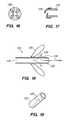
- FIGS. 18-19show a multiport tip which may be incorporated on the distal end of the second tubular member to allow for slow release of a liquid embolic onto the sealing element prior to delivery of the bulk of the embolic into the interior of the cavity to be occluded.
- FIGS. 20-22show a variation of the device in which the first tubular member acts as a sheath for the sealing element during deployment.
- the first tubular membercan then be retracted over the sealing element, releasing a catch on the second end of the sealing element.
- a distal end of the first tubular membercan then engage the catch and collapse or cinch the sealing element into the deployed shape.
- FIG. 23shows a schematic side view of an occlusive device comprising a tethering element designed to protrude into a cavity and engage an embolic inserted therein to lock the embolic and device together.
- An occlusion device 100comprises first and second tubular members 110 , 120 attached at their distal ends 112 , 122 to a collapsible sealing element 130 . See FIGS. 1-3 and 20 - 22 . Movement of the tubular members relative to one another allows the manipulation of the sealing element to block an orifice.
- the tubular membersare generally elongate and flexible, to permit their manipulation throughout the body of a patient.
- the devicewill be introduced through the vasculature, for example through a leg vein, to treat an aneurysm within a blood vessel.
- the tubular membershave central lumens 114 , 124 extending longitudinally therethrough, with the second tubular member 120 located within the lumen 114 of the first tubular member 110 .
- the tubular membersare generally axially aligned, and may be coaxial.
- the second tubular membermay substantially occupy the lumen of the first tubular member, or a space may be provided between the tubular members, permitting introduction of a fluid (for example a contrast agent) into the interior of the sealing element 130 .
- a cathetermay be used to introduce a fluid into the sealing element, where desired, or one or more ports fluidly connected to the interior of the sealing element may be incorporated into the device.
- the second tubular membercommunicates with the interior of the aneurysm, and its lumen can be used for positioning on a guidewire and introducing embolics into an aneurysm or other cavity.
- the second tubular membermay be detached prior to introduction of all or some of the embolics, allowing for introduction of larger embolic devices which can be received within the larger lumen of the first tubular member once the second tubular member is removed. Where the second tubular member is detached first and removed, the first tubular member then communicates with the interior of the aneurysm.
- the tubular memberscan be made of any suitable flexible material which can function in the device as described, and may be a composite of materials.
- Polymeric materialsincluding copolymeric materials, can be used, for example polytetrafluoroethylene (PTFE), polyether-block co-polyamide copolymers (e.g., PEBAX®), or urethane.
- Flexible metalscan also be used, for example wires such as stainless steel wire, nitinol, etc. Materials can be incorporated to improve kink resistance. Hydrophilic coatings can be added to improve bioacceptability.
- a tubular membercan comprise an inner layer of PTFE, a stainless steel wire winding, a polymeric layer, and a dip coating of a hydrophilic agent.
- the tubular membersmay incorporate visualization or contrast agents; for example, the second tubular member 120 may incorporate a contrast agent 123 allowing determination of the position of the tip during introduction.
- the first and second tubular memberscan be manually positioned individually, or can be connected to a device capable of controlling their movements.
- the tubular memberscan incorporate hubs at a proximal end for attachment to such a device.
- a handlemay be included to lock the outer and inner tubular members and thereby prevent the premature deployment of the device during delivery.
- the second lumen 124may be disposed around a guidewire 180 used to guide the introduction of the device into a desired cavity or orifice, or the device may be used without a guidewire. See FIGS. 1-2 .
- a radioopaque materialmay be incorporated into the guidewire, one or both of the tubular members, or all three, to permit visualization of their positions during use.
- the detachable sealing element described hereinrequires no unique guidewire that must be specially manufactured, but allows the use of unmodified commercially available guidewires, thereby decreasing costs and simplifying manufacture and operation.
- the device of the present inventionrequires no physical attachment to the guidewire, and so can in principle be used with any guidewire of suitable dimensions.
- the deviceadvantageously displays a low profile, simplifying introduction of the device and permitting introduction into more remote areas of, for example, the vasculature, then could be reached by a thicker device.
- the sealing elementis detachably connected at its first and second ends 132 , 134 respectively to the first and second tubular members at their distal ends, allowing the sealing element to remain implanted within the orifice once detached.
- distal endis meant a position at or near the distal end of a tubular member, and does not preclude the tubular member from extending distally past the point to which the sealing element is attached, such that portions of the tubular members may be included in that part of the device which is detached.
- an extension of the second tubular member beyond the sealing elementis included to permit more advanced introduction of an embolic 170 past the sealing element.
- the sealing elementincludes a catch or lever system 137 at its first end for engagement of the first distal end 112 of the first tubular member by abutment, and is not otherwise connected to the first tubular member. Extension of the first tubular member relative to the second tubular member when this abutment system is engaged causes the cinching or collapse of the sealing element into the deployed shape. See FIGS. 20-22 .
- the detachable connections 140 , 140 a to the first and second tubular membersmay be of the same type, or may be different. Any form of connection that allows for implantation of the device and that can be detached upon deployment of the sealing element can be used.
- the connectionmay be an adhesive connection, a friction fit, a ring and joining rib, a mechanically detachable joint, or an electrolytically detachable joint.
- at least one of the detachable connectionsis an electrolytic joint constructed of a material that is susceptible to electrolytic dissolution in blood and that dissolves in response to an intentionally timed and applied electrolytic signal.
- An example of detachment of the second tubular member 120is shown in FIGS. 11-12 .
- the lumen 124 and the second tubular membercan be formed so that the distal end 122 will cleanly separate upon activation of electrolytically detachable connection 140 a.
- the sealing element 130can be made of any material suitable for the desired application.
- the sealing elementcan be formed of a bio-compatible fabric-like material, such as a braided, woven polymeric material, or a nonwoven polymeric material such as an electrostatically spun membrane for example as described in U.S. Pat. No. 6,156,064 issued Dec. 5, 2000 to Choinard, and Medical Textile Structures: An Overview by Bhupender S. Gupta (Medical Plastics and Biomaterials, January 1998; http://www.devicelink.com/mpb/archive/98/01/001.html).
- the sealing elementmay comprise one or more polymers, for example polyethylene, polypropylene, polyvinylchloride, a polyamide (e.g., Nylon), polyurethanes, polyvinylpyrrolidone, polyvinyl alchohols, polyvinylacetate, cellulose acetate, polystyrene, polytetrafluoroethylene, a polyester (e.g. polyethylene terphthalate (Dacron)), polyurethane, silk, and cotton.
- the sealing elementcan comprise one or more biodegradable or bioabsorbable materials, for example polylactic acid, polyglycolic acid, or a copolymer thereof.
- a radio-opaque material 135can be woven or otherwise incorporated into the sealing element (i.e., tantulum platinum, gold, etc.) to facilitate and assist in guidance through a vascular system utilizing radiography or fluoroscopy.
- FIG. 3shows a perspective view of an occlusive device in the collapsed or deployed shape, with the generally disklike sealing element extending generally radially outwards. Radioopaque fiber 135 is shown woven into the sealing element.
- the sealing elementcan comprise an elastomer, allowing it to be filled with a liquid (e.g. a contrast agent 136 ) and can expand, and can then be contracted upon introduction of an embolic 170 into the cavity and thereby aid in monitoring of the process. See FIGS. 8-10 .
- the sealing elementcan comprise or be made entirely of a metallic wire, for example platinum wire or stainless steel wire, which can itself be radioopaque.
- the sealing elementmay be formed of a material (e.g., nitinol) capable of assuming a shape memory and may have a predetermined deployed shape.
- the sealing elementmay be porous or nonporous.
- the meshmay be preclotted prior to insertion into the cavity using clotting factors which may optionally be obtained from the patient being treated.
- the sealing elementmay take the form of a braided tube comprising multiple different materials, which can impart different properties, e.g. polymer yams, metal wires, radioopaque strands, etc.
- the sealing element 130may assume any generally flattened shape when collapsed.
- the inherent shape of the collapsed sealing elementcan be controlled in any of various ways, for example by using combination(s) of different materials to form the element, or by using combinations of materials of different thickness.
- the sealing elementwill assume a generally disklike shape in the collapsed shape, which is generally collapsed longitudinally along the axis of the second, or both, tubular members, and extends generally radially outwards therefrom.
- the tubular membermay include one or more folds and/or grooves to cause the sealing element to fold at a predetermined location when collapsed.
- the tubular membersare disposed so as to retain the sealing element in an extended shape generally extended longitudinally along the axis of the second, or both, tubular members during introduction of the device, and can be moved relative to one another, typically sliding along one another coaxially to expand and contract the sealing element.
- the sealing elementmay be so maneuvered using the tubular members a number of times during introduction in order to obtain a desirable position. This control scheme in those variations allows for the reversible manipulation of the sealing element while being deployed.
- the sealing elementcan be protected by a retractable sheath 160 that can cover the sealing element during introduction of the device.
- the sheathcan then be retracted in the vicinity of the passage or orifice, exposing the sealing element and allowing its use as a seal.
- the sheathitself may be used to position the sealing element in certain variations, and the outer tubular member may act as the sheath.
- the sheath 160also serving as first outer tubular member 110 ) protects the sealing element 130 during positioning.
- the sheath 160can then be retracted to release the sealing element and catches or levers 137 on the second end of the sealing element.
- the distal end of the sheath 160is shaped so that it can engage the catch system 137 and thereby by used to push the second end of the sealing element, comprising locking elements 150 a in the variation shown in FIGS. 20-22 , into the deployed shape.
- the sheath 160can be further pushed to engage the locking system 150 , 150 a .
- the position of the sheathcan be maintained in one place engaging the levers while the inner tubular member is pulled or retracted, or both tubular members may be moved.
- the devicemay incorporate a multiport tip with ports 125 at its distal end 122 for deploying an embolic 170 distal to the device to prevent efflux through the sealing element 130 . See FIGS. 18-19 .
- the sealing elementis a porous material such as mesh
- the operatorcan first introduce a small amount of the embolic to contact the mesh and allow it to harden prior to introduction of a sufficient amount of embolic.
- a cathetermay alternatively be used to introduce a liquid embolic or other agent into the cavity, and may pass through the second lumen 124 .
- the second lumen 124itself may also be used to deliver the embolic.
- embolic 170 suitable for occluding a cavitycan be used.
- Exemplary embolics which can be usedinclude hardening agents, coils (e.g. “liquid coils”) which may be delivered over a guidewire passing through the device, fibers, particles, supporting members or microspheres, or combinations thereof.
- the embolic material, as ultimately deployed,must be capable of retention within the cavity by the sealing element being used.
- the devicemay comprise a tethering element or elements 172 ( FIG. 23 ) that anchors the embolic to the sealing element, which may extend from the tubular member(s), their lumen(s), and/or the sealing element.
- the anchoringmay take place through any available mechanism, for example through physical entanglement (e.g., where the embolic comprises coils), through entrapment of the element within a hardening embolic, by entrapment within the embolus, or by combinations of mechanisms.
- additional loops of materiale.g. wire, fiber or yarn
- Diffusing tipsmay be used on the end of the catheter or port used to introduce the embolic and thereby allow the embolic to be deployed evenly.
- the devicemay incorporate one or more locking elements 150 , 150 a tending to fix the sealing element in the deployed shape upon engagement. See, for example, FIGS. 4-6 .
- Any locking mechanism that can lock the sealing element into the deployed shapecan be used.
- Exemplary locking mechanisms suitable for use in the occlusive deviceinclude latching systems, dimples, detents including rim and bump-ring systems, friction-fit elements, entanglement systems, and locking barbs ( FIGS. 4-6 ).
- Entanglement systemscan include, for example, hook-and-loop systems for example VELCRO® fasteners), and systems in which a slidable member such as a tube or post passes into a mesh or braid (e.g., nitinol braid) which seals behind the end of the slidable member and prevents its removal.
- Mechanical expansion elementscan be incorporated as locking elements, wherein movement of the tubular members releases an expandible element (for example, a ring or strips) once the tubular members exceed a particular relative offset which prevents return to the extended shape. Engagement of the locking mechanism causes the sealing element to at least strongly resist movement away from the collapsed shape, and may effectively permanently lock the sealing element in that position.
- the locking elements 150 , 150 aare located on or near the distal ends 112 , 122 of the tubular members, but in principle can be located anywhere on the tubular members that allow them to be locked in a position fixing the sealing element in the deployed shape.
- the locking mechanism 150can be located within the sealing element 130 itself.
- hook-and-loop memberscan be located within the sealing element so that, when the sealing element is moved into the deployed shape, the inner surface of the sealing element, brought into opposition by the movement of the first and second tubular members, is locked into the deployed shape by virtue of attachment of the hooks and loops brought into opposition.
- Locking mechanismsmay be located on the tubular members, on the sealing element, or on the tubular members and the sealing element.
- the devicemay include one or more valves 128 or valve-like elements controlling the passage of fluid through the lumen(s) of the tubular members. See FIGS. 13-17 . These valves can be used to prevent egress of an embolic 170 from an aneurysm 190 after occlusion. Any element suitable for sealing the lumen(s) can be employed as a valve.
- the valvesmay take the form of flaps ( FIGS. 16-17 ) that are released in conjunction with detachment of the device, or may take the form of an annular seal ( FIGS. 13-15 ) which is similarly released on detachment of the device to seal the lumen.
- the valves 128need not only deploy in conjunction with detachment of the device, and their deployment may be separately controllable.
- the devicemay be provided sealed in a package in single use form, and may be provided sterilized for performing a medical procedure using any suitable sterilizing technique, for example using heat, ultraviolet light, radiation, and/or a sterilizing gas (e.g., ethylene oxide).
- a sterilizing gase.g., ethylene oxide
- the devicemay be packaged with a guidewire suitable for use in introducing the device into an orifice or body cavity.
- the devices described hereincan, in principle, be used for blocking any orifice or for occluding any cavity within the body, limited only by accessibility to the device and by the shape and size of the orifice or cavity.
- the devicemay be used to seal an atrial septal defect, or to seal a penetrating wound.
- the devicemay be used as a temporary or permanent seal.
- the devicewill be used to seal an aneurysm 190 ( FIG. 7 ), and may be employed with an embolic as described above.
- the sealing element 130is positioned within the aneurysm 190 so that it occludes the neck 191 .
- An embolicmay then be introduced and the device detached in place.
- the devicemay be removed after the embolic has hardened or otherwise will maintain an occlusion of the aneurysm or other cavity in the absence of the sealing element 130 .
- a retention devicemay optionally be employed to assist in maintaining the occlusion of the cavity.
Landscapes
- Health & Medical Sciences (AREA)
- Surgery (AREA)
- Life Sciences & Earth Sciences (AREA)
- Heart & Thoracic Surgery (AREA)
- Molecular Biology (AREA)
- Vascular Medicine (AREA)
- Engineering & Computer Science (AREA)
- Biomedical Technology (AREA)
- Reproductive Health (AREA)
- Medical Informatics (AREA)
- Nuclear Medicine, Radiotherapy & Molecular Imaging (AREA)
- Animal Behavior & Ethology (AREA)
- General Health & Medical Sciences (AREA)
- Public Health (AREA)
- Veterinary Medicine (AREA)
- Neurosurgery (AREA)
- Surgical Instruments (AREA)
Abstract
Description
Claims (13)
Priority Applications (3)
| Application Number | Priority Date | Filing Date | Title |
|---|---|---|---|
| US11/748,221US7892248B2 (en) | 2003-01-07 | 2007-05-14 | Occlusive cinching devices and methods of use |
| US13/013,044US20110118768A1 (en) | 2003-01-07 | 2011-01-25 | Occlusive cinching devices and methods of use |
| US14/246,772US20140207162A1 (en) | 2003-01-07 | 2014-04-07 | Occlusive cinching devices and methods of use |
Applications Claiming Priority (2)
| Application Number | Priority Date | Filing Date | Title |
|---|---|---|---|
| US10/338,514US7229454B2 (en) | 2003-01-07 | 2003-01-07 | Occlusive cinching devices and methods of use |
| US11/748,221US7892248B2 (en) | 2003-01-07 | 2007-05-14 | Occlusive cinching devices and methods of use |
Related Parent Applications (1)
| Application Number | Title | Priority Date | Filing Date |
|---|---|---|---|
| US10/338,514ContinuationUS7229454B2 (en) | 2003-01-07 | 2003-01-07 | Occlusive cinching devices and methods of use |
Related Child Applications (1)
| Application Number | Title | Priority Date | Filing Date |
|---|---|---|---|
| US13/013,044ContinuationUS20110118768A1 (en) | 2003-01-07 | 2011-01-25 | Occlusive cinching devices and methods of use |
Publications (2)
| Publication Number | Publication Date |
|---|---|
| US20070213764A1 US20070213764A1 (en) | 2007-09-13 |
| US7892248B2true US7892248B2 (en) | 2011-02-22 |
Family
ID=32681467
Family Applications (4)
| Application Number | Title | Priority Date | Filing Date |
|---|---|---|---|
| US10/338,514Expired - LifetimeUS7229454B2 (en) | 2003-01-07 | 2003-01-07 | Occlusive cinching devices and methods of use |
| US11/748,221Expired - LifetimeUS7892248B2 (en) | 2003-01-07 | 2007-05-14 | Occlusive cinching devices and methods of use |
| US13/013,044AbandonedUS20110118768A1 (en) | 2003-01-07 | 2011-01-25 | Occlusive cinching devices and methods of use |
| US14/246,772AbandonedUS20140207162A1 (en) | 2003-01-07 | 2014-04-07 | Occlusive cinching devices and methods of use |
Family Applications Before (1)
| Application Number | Title | Priority Date | Filing Date |
|---|---|---|---|
| US10/338,514Expired - LifetimeUS7229454B2 (en) | 2003-01-07 | 2003-01-07 | Occlusive cinching devices and methods of use |
Family Applications After (2)
| Application Number | Title | Priority Date | Filing Date |
|---|---|---|---|
| US13/013,044AbandonedUS20110118768A1 (en) | 2003-01-07 | 2011-01-25 | Occlusive cinching devices and methods of use |
| US14/246,772AbandonedUS20140207162A1 (en) | 2003-01-07 | 2014-04-07 | Occlusive cinching devices and methods of use |
Country Status (3)
| Country | Link |
|---|---|
| US (4) | US7229454B2 (en) |
| AU (1) | AU2003293371A1 (en) |
| WO (1) | WO2004062511A1 (en) |
Cited By (22)
| Publication number | Priority date | Publication date | Assignee | Title |
|---|---|---|---|---|
| EP3572010A1 (en)* | 2018-05-25 | 2019-11-27 | DePuy Synthes Products, Inc. | Aneurysm device and delivery system |
| US10905430B2 (en) | 2018-01-24 | 2021-02-02 | DePuy Synthes Products, Inc. | Aneurysm device and delivery system |
| US10939915B2 (en) | 2018-05-31 | 2021-03-09 | DePuy Synthes Products, Inc. | Aneurysm device and delivery system |
| US11076860B2 (en) | 2014-03-31 | 2021-08-03 | DePuy Synthes Products, Inc. | Aneurysm occlusion device |
| US11076861B2 (en) | 2018-10-12 | 2021-08-03 | DePuy Synthes Products, Inc. | Folded aneurysm treatment device and delivery method |
| US11123077B2 (en) | 2018-09-25 | 2021-09-21 | DePuy Synthes Products, Inc. | Intrasaccular device positioning and deployment system |
| US11134953B2 (en) | 2019-02-06 | 2021-10-05 | DePuy Synthes Products, Inc. | Adhesive cover occluding device for aneurysm treatment |
| US11154302B2 (en) | 2014-03-31 | 2021-10-26 | DePuy Synthes Products, Inc. | Aneurysm occlusion device |
| US11272939B2 (en) | 2018-12-18 | 2022-03-15 | DePuy Synthes Products, Inc. | Intrasaccular flow diverter for treating cerebral aneurysms |
| US11278292B2 (en) | 2019-05-21 | 2022-03-22 | DePuy Synthes Products, Inc. | Inverting braided aneurysm treatment system and method |
| US11337706B2 (en) | 2019-03-27 | 2022-05-24 | DePuy Synthes Products, Inc. | Aneurysm treatment device |
| US11406392B2 (en) | 2018-12-12 | 2022-08-09 | DePuy Synthes Products, Inc. | Aneurysm occluding device for use with coagulating agents |
| US11413046B2 (en) | 2019-05-21 | 2022-08-16 | DePuy Synthes Products, Inc. | Layered braided aneurysm treatment device |
| US11457926B2 (en) | 2019-12-18 | 2022-10-04 | DePuy Synthes Products, Inc. | Implant having an intrasaccular section and intravascular section |
| US11497504B2 (en) | 2019-05-21 | 2022-11-15 | DePuy Synthes Products, Inc. | Aneurysm treatment with pushable implanted braid |
| US11583282B2 (en) | 2019-05-21 | 2023-02-21 | DePuy Synthes Products, Inc. | Layered braided aneurysm treatment device |
| US11583288B2 (en) | 2018-08-08 | 2023-02-21 | DePuy Synthes Products, Inc. | Delivery of embolic braid |
| US11596412B2 (en) | 2018-05-25 | 2023-03-07 | DePuy Synthes Products, Inc. | Aneurysm device and delivery system |
| US11602350B2 (en) | 2019-12-05 | 2023-03-14 | DePuy Synthes Products, Inc. | Intrasaccular inverting braid with highly flexible fill material |
| US11607226B2 (en) | 2019-05-21 | 2023-03-21 | DePuy Synthes Products, Inc. | Layered braided aneurysm treatment device with corrugations |
| US11672542B2 (en) | 2019-05-21 | 2023-06-13 | DePuy Synthes Products, Inc. | Aneurysm treatment with pushable ball segment |
| US11672543B2 (en) | 2017-02-23 | 2023-06-13 | DePuy Synthes Products, Inc. | Aneurysm method and system |
Families Citing this family (54)
| Publication number | Priority date | Publication date | Assignee | Title |
|---|---|---|---|---|
| US8088060B2 (en) | 2000-03-15 | 2012-01-03 | Orbusneich Medical, Inc. | Progenitor endothelial cell capturing with a drug eluting implantable medical device |
| US9522217B2 (en) | 2000-03-15 | 2016-12-20 | Orbusneich Medical, Inc. | Medical device with coating for capturing genetically-altered cells and methods for using same |
| US7029486B2 (en)* | 2000-09-26 | 2006-04-18 | Microvention, Inc. | Microcoil vaso-occlusive device with multi-axis secondary configuration |
| US20080208160A9 (en)* | 2003-01-10 | 2008-08-28 | Mawad Michel E | Microcatheter including swellable tip |
| US20060155323A1 (en) | 2005-01-07 | 2006-07-13 | Porter Stephen C | Intra-aneurysm devices |
| US7744652B2 (en)* | 2006-01-23 | 2010-06-29 | Hesham Morsi | Aneurysm sealing device |
| US8372114B2 (en)* | 2006-11-13 | 2013-02-12 | Electroformed Stents, Inc. | Over-the-wire exclusion device and system for delivery |
| US20110022149A1 (en) | 2007-06-04 | 2011-01-27 | Cox Brian J | Methods and devices for treatment of vascular defects |
| US8465515B2 (en) | 2007-08-29 | 2013-06-18 | Ethicon Endo-Surgery, Inc. | Tissue retractors |
| EP2214584A2 (en)* | 2007-11-15 | 2010-08-11 | Medizinische Universität Wien | Method and device for carrying out a percrestale sinus lift |
| US8128559B2 (en) | 2007-11-26 | 2012-03-06 | Ethicon Endo-Surgery, Inc. | Tissue retractors |
| US8517931B2 (en)* | 2007-11-26 | 2013-08-27 | Ethicon Endo-Surgery, Inc. | Tissue retractors |
| US10716573B2 (en) | 2008-05-01 | 2020-07-21 | Aneuclose | Janjua aneurysm net with a resilient neck-bridging portion for occluding a cerebral aneurysm |
| US10028747B2 (en) | 2008-05-01 | 2018-07-24 | Aneuclose Llc | Coils with a series of proximally-and-distally-connected loops for occluding a cerebral aneurysm |
| US20240225660A1 (en)* | 2008-05-01 | 2024-07-11 | Aneuclose Llc | Systems and Methods for Forming and Deploying the Janjua Aneurysm Net plus Bridge (JAN-B) for Cerebral Aneurysm Occlusion |
| AU2009242528B2 (en) | 2008-05-02 | 2015-12-10 | Microvention, Inc. | Filamentary devices for treatment of vascular defects |
| WO2010022180A1 (en)* | 2008-08-19 | 2010-02-25 | Micro Therapeutics, Inc. | Detachable tip microcatheter |
| DE102008042798A1 (en)* | 2008-10-13 | 2010-04-15 | Biotronik Vi Patent Ag | Catheter with an application device for liquid active substances |
| WO2010068793A1 (en)* | 2008-12-10 | 2010-06-17 | Microvention, Inc. | Microcatheter |
| US10702275B2 (en)* | 2009-02-18 | 2020-07-07 | St. Jude Medical Cardiology Division, Inc. | Medical device with stiffener wire for occluding vascular defects |
| BR112012010758A2 (en) | 2009-11-05 | 2019-09-24 | Sequent Medical Inc | multilayer filament devices for treatment of vascular defects |
| US9358140B1 (en) | 2009-11-18 | 2016-06-07 | Aneuclose Llc | Stent with outer member to embolize an aneurysm |
| US9005234B2 (en)* | 2010-12-30 | 2015-04-14 | Cook Medical Technologies Llc | Occlusion device |
| AU2012222114B2 (en) | 2011-02-25 | 2016-06-16 | Microvention, Inc. | Reinforced balloon catheter |
| US9198668B2 (en) | 2011-08-04 | 2015-12-01 | Cook Medical Technologies Llc | Cerebral aneurysm closure device |
| US10124087B2 (en) | 2012-06-19 | 2018-11-13 | Covidien Lp | Detachable coupling for catheter |
| US10188396B2 (en) | 2012-08-06 | 2019-01-29 | Covidien Lp | Apparatus and method for delivering an embolic composition |
| US10327781B2 (en)* | 2012-11-13 | 2019-06-25 | Covidien Lp | Occlusive devices |
| US9955976B2 (en) | 2013-08-16 | 2018-05-01 | Sequent Medical, Inc. | Filamentary devices for treatment of vascular defects |
| US9078658B2 (en) | 2013-08-16 | 2015-07-14 | Sequent Medical, Inc. | Filamentary devices for treatment of vascular defects |
| US9629635B2 (en) | 2014-04-14 | 2017-04-25 | Sequent Medical, Inc. | Devices for therapeutic vascular procedures |
| US10130372B2 (en) | 2014-04-30 | 2018-11-20 | Cerus Endovascular Limited | Occlusion Device |
| US9814466B2 (en) | 2014-08-08 | 2017-11-14 | Covidien Lp | Electrolytic and mechanical detachment for implant delivery systems |
| US9808256B2 (en)* | 2014-08-08 | 2017-11-07 | Covidien Lp | Electrolytic detachment elements for implant delivery systems |
| US9717503B2 (en) | 2015-05-11 | 2017-08-01 | Covidien Lp | Electrolytic detachment for implant delivery systems |
| US10307168B2 (en) | 2015-08-07 | 2019-06-04 | Terumo Corporation | Complex coil and manufacturing techniques |
| EP4011303B1 (en) | 2015-12-07 | 2024-06-12 | Cerus Endovascular Limited | Occlusion device |
| AU2017218115B2 (en) | 2016-02-10 | 2020-03-05 | Microvention, Inc. | Devices for vascular occlusion |
| WO2017153603A1 (en) | 2016-03-11 | 2017-09-14 | Cerus Endovascular Limited | Occlusion device |
| US10828037B2 (en) | 2016-06-27 | 2020-11-10 | Covidien Lp | Electrolytic detachment with fluid electrical connection |
| US10828039B2 (en) | 2016-06-27 | 2020-11-10 | Covidien Lp | Electrolytic detachment for implantable devices |
| US11051822B2 (en) | 2016-06-28 | 2021-07-06 | Covidien Lp | Implant detachment with thermal activation |
| US10576099B2 (en) | 2016-10-21 | 2020-03-03 | Covidien Lp | Injectable scaffold for treatment of intracranial aneurysms and related technology |
| JP7414710B2 (en) | 2017-08-21 | 2024-01-16 | シーラス エンドバスキュラー リミテッド | occlusion device |
| CN113573650B (en) | 2019-03-15 | 2024-05-28 | 后续医疗股份有限公司 | Silk device with flexible connector for treating vascular defects |
| US11559309B2 (en) | 2019-03-15 | 2023-01-24 | Sequent Medical, Inc. | Filamentary devices for treatment of vascular defects |
| CN113573765B (en) | 2019-03-15 | 2024-08-13 | 美科微先股份有限公司 | Silk device for treating vascular defects |
| US11832828B2 (en)* | 2019-05-24 | 2023-12-05 | Medtronic, Inc. | Left atrial appendage occlusion device |
| US11707351B2 (en) | 2019-08-19 | 2023-07-25 | Encompass Technologies, Inc. | Embolic protection and access system |
| WO2021092618A1 (en) | 2019-11-04 | 2021-05-14 | Covidien Lp | Devices, systems, and methods for treatment of intracranial aneurysms |
| US11406404B2 (en) | 2020-02-20 | 2022-08-09 | Cerus Endovascular Limited | Clot removal distal protection methods |
| US12023034B2 (en) | 2020-03-11 | 2024-07-02 | Microvention, Inc. | Devices for treatment of vascular defects |
| US12070220B2 (en) | 2020-03-11 | 2024-08-27 | Microvention, Inc. | Devices having multiple permeable shells for treatment of vascular defects |
| US20210282789A1 (en) | 2020-03-11 | 2021-09-16 | Microvention, Inc. | Multiple layer devices for treatment of vascular defects |
Citations (34)
| Publication number | Priority date | Publication date | Assignee | Title |
|---|---|---|---|---|
| US4710192A (en) | 1985-12-30 | 1987-12-01 | Liotta Domingo S | Diaphragm and method for occlusion of the descending thoracic aorta |
| US4923464A (en) | 1985-09-03 | 1990-05-08 | Becton, Dickinson And Company | Percutaneously deliverable intravascular reconstruction prosthesis |
| US5122136A (en) | 1990-03-13 | 1992-06-16 | The Regents Of The University Of California | Endovascular electrolytically detachable guidewire tip for the electroformation of thrombus in arteries, veins, aneurysms, vascular malformations and arteriovenous fistulas |
| US5354295A (en) | 1990-03-13 | 1994-10-11 | Target Therapeutics, Inc. | In an endovascular electrolytically detachable wire and tip for the formation of thrombus in arteries, veins, aneurysms, vascular malformations and arteriovenous fistulas |
| US5423829A (en) | 1993-11-03 | 1995-06-13 | Target Therapeutics, Inc. | Electrolytically severable joint for endovascular embolic devices |
| US5562726A (en) | 1991-10-25 | 1996-10-08 | Cook Incorporated | Expandable transluminal graft prosthesis for repair of aneurysm and method for implanting |
| US5624449A (en) | 1993-11-03 | 1997-04-29 | Target Therapeutics | Electrolytically severable joint for endovascular embolic devices |
| US5855578A (en) | 1990-03-13 | 1999-01-05 | The Regents Of The University Of California | Endovascular electrolytically detachable wire and tip for the formation of thrombus in arteries, veins, aneurysms, vascular malformations and arteriovenous fistulas |
| WO1999002093A1 (en) | 1997-07-10 | 1999-01-21 | Scimed Life Systems, Inc. | Removable occlusion system for aneurysm neck |
| WO1999005977A1 (en) | 1997-08-04 | 1999-02-11 | Boston Scientific Corporation | Occlusion system for aneurysm repair |
| US5891128A (en) | 1994-12-30 | 1999-04-06 | Target Therapeutics, Inc. | Solderless electrolytically severable joint for detachable devices placed within the mammalian body |
| US5916235A (en) | 1997-08-13 | 1999-06-29 | The Regents Of The University Of California | Apparatus and method for the use of detachable coils in vascular aneurysms and body cavities |
| US5935148A (en) | 1998-06-24 | 1999-08-10 | Target Therapeutics, Inc. | Detachable, varying flexibility, aneurysm neck bridge |
| US5941888A (en) | 1998-02-18 | 1999-08-24 | Target Therapeutics, Inc. | Vaso-occlusive member assembly with multiple detaching points |
| US5964797A (en) | 1996-08-30 | 1999-10-12 | Target Therapeutics, Inc. | Electrolytically deployable braided vaso-occlusion device |
| US5984929A (en) | 1997-08-29 | 1999-11-16 | Target Therapeutics, Inc. | Fast detaching electronically isolated implant |
| US6036720A (en) | 1997-12-15 | 2000-03-14 | Target Therapeutics, Inc. | Sheet metal aneurysm neck bridge |
| WO2000013593A1 (en) | 1998-09-04 | 2000-03-16 | Boston Scientific Limited (Incorporated In Ireland) | Detachable aneurysm neck closure patch |
| US6063070A (en) | 1997-08-05 | 2000-05-16 | Target Therapeutics, Inc. | Detachable aneurysm neck bridge (II) |
| US6077260A (en) | 1998-02-19 | 2000-06-20 | Target Therapeutics, Inc. | Assembly containing an electrolytically severable joint for endovascular embolic devices |
| US6086577A (en) | 1997-08-13 | 2000-07-11 | Scimed Life Systems, Inc. | Detachable aneurysm neck bridge (III) |
| US6156064A (en) | 1998-08-14 | 2000-12-05 | Schneider (Usa) Inc | Stent-graft-membrane and method of making the same |
| US6156061A (en) | 1997-08-29 | 2000-12-05 | Target Therapeutics, Inc. | Fast-detaching electrically insulated implant |
| US6179860B1 (en)* | 1998-08-19 | 2001-01-30 | Artemis Medical, Inc. | Target tissue localization device and method |
| US6193708B1 (en) | 1997-08-05 | 2001-02-27 | Scimed Life Systems, Inc. | Detachable aneurysm neck bridge (I) |
| US6344041B1 (en) | 1996-07-26 | 2002-02-05 | David Kupiecki | Aneurysm closure device assembly |
| US6375669B1 (en) | 1998-04-28 | 2002-04-23 | Microvention, Inc. | Apparatus and method for vascular embolization |
| US6383171B1 (en) | 1999-10-12 | 2002-05-07 | Allan Will | Methods and devices for protecting a passageway in a body when advancing devices through the passageway |
| US6397850B1 (en) | 2000-02-09 | 2002-06-04 | Scimed Life Systems Inc | Dual-mode apparatus and method for detection of embolic device detachment |
| US6425893B1 (en) | 1990-03-13 | 2002-07-30 | The Regents Of The University Of California | Method and apparatus for fast electrolytic detachment of an implant |
| WO2002069783A2 (en) | 2000-10-24 | 2002-09-12 | Concentric Medical, Inc. | Device and methods for treating vascular malformations |
| US6454780B1 (en) | 2001-06-21 | 2002-09-24 | Scimed Life Systems, Inc. | Aneurysm neck obstruction device |
| US6635068B1 (en)* | 1998-02-10 | 2003-10-21 | Artemis Medical, Inc. | Occlusion, anchoring, tensioning and flow direction apparatus and methods for use |
| US6994718B2 (en) | 2003-10-29 | 2006-02-07 | Medtronic Vascular, Inc. | Distal protection device for filtering and occlusion |
Family Cites Families (10)
| Publication number | Priority date | Publication date | Assignee | Title |
|---|---|---|---|---|
| US4676249A (en)* | 1986-05-19 | 1987-06-30 | Cordis Corporation | Multi-mode guidewire |
| US5853422A (en)* | 1996-03-22 | 1998-12-29 | Scimed Life Systems, Inc. | Apparatus and method for closing a septal defect |
| US5979126A (en)* | 1996-06-05 | 1999-11-09 | Kajima Corporation | Seismic response control method for structure |
| US5861003A (en)* | 1996-10-23 | 1999-01-19 | The Cleveland Clinic Foundation | Apparatus and method for occluding a defect or aperture within body surface |
| US5947982A (en)* | 1997-04-02 | 1999-09-07 | Smith & Nephew, Inc. | Suture-passing forceps |
| US5868708A (en)* | 1997-05-07 | 1999-02-09 | Applied Medical Resources Corporation | Balloon catheter apparatus and method |
| US5908407A (en)* | 1997-07-25 | 1999-06-01 | Neuroperfusion, Inc. | Retroperfusion catheter apparatus and method |
| US6450989B2 (en)* | 1998-04-27 | 2002-09-17 | Artemis Medical, Inc. | Dilating and support apparatus with disease inhibitors and methods for use |
| US6375668B1 (en)* | 1999-06-02 | 2002-04-23 | Hanson S. Gifford | Devices and methods for treating vascular malformations |
| US6364900B1 (en)* | 1999-07-14 | 2002-04-02 | Richard R. Heuser | Embolism prevention device |
- 2003
- 2003-01-07USUS10/338,514patent/US7229454B2/ennot_activeExpired - Lifetime
- 2003-12-05AUAU2003293371Apatent/AU2003293371A1/ennot_activeAbandoned
- 2003-12-05WOPCT/US2003/038506patent/WO2004062511A1/ennot_activeApplication Discontinuation
- 2007
- 2007-05-14USUS11/748,221patent/US7892248B2/ennot_activeExpired - Lifetime
- 2011
- 2011-01-25USUS13/013,044patent/US20110118768A1/ennot_activeAbandoned
- 2014
- 2014-04-07USUS14/246,772patent/US20140207162A1/ennot_activeAbandoned
Patent Citations (52)
| Publication number | Priority date | Publication date | Assignee | Title |
|---|---|---|---|---|
| US4923464A (en) | 1985-09-03 | 1990-05-08 | Becton, Dickinson And Company | Percutaneously deliverable intravascular reconstruction prosthesis |
| US4710192A (en) | 1985-12-30 | 1987-12-01 | Liotta Domingo S | Diaphragm and method for occlusion of the descending thoracic aorta |
| US5947962A (en) | 1990-03-13 | 1999-09-07 | The Regents Of The University Of California | Endovascular electrolytically detachable wire and tip for the formation of thrombus in arteries veins aneurysms vascular malformations and arteriovenous fistulas |
| US5944714A (en) | 1990-03-13 | 1999-08-31 | The Regents Of The University Of California | Endovascular electrolytically detachable wire and tip for the formation of thrombus in arteries, veins, aneurysms, vascular malformations and arteriovenous fistulas |
| US6066133A (en) | 1990-03-13 | 2000-05-23 | The Regents Of The University Of California | Endovascular electrolytically detachable wire and tip for the formation of thrombus in arteries, veins, aneurysms, vascular malformations and arteriovenous fistulas |
| US5976126A (en) | 1990-03-13 | 1999-11-02 | The Regents Of The University Of California | Endovascular electrolytically detachable wire and tip formation of thrombus in arteries, veins, aneurysms, vascular malformations and arteriovenous fistulas |
| US5947963A (en) | 1990-03-13 | 1999-09-07 | The Regents Of The University Of California | Endovascular electrolytically detachable wire and tip for the formation of thrombus in arteries, veins, aneurysms, vascular malformations and arteriovenous fistulas |
| US5855578A (en) | 1990-03-13 | 1999-01-05 | The Regents Of The University Of California | Endovascular electrolytically detachable wire and tip for the formation of thrombus in arteries, veins, aneurysms, vascular malformations and arteriovenous fistulas |
| US6425893B1 (en) | 1990-03-13 | 2002-07-30 | The Regents Of The University Of California | Method and apparatus for fast electrolytic detachment of an implant |
| US5354295A (en) | 1990-03-13 | 1994-10-11 | Target Therapeutics, Inc. | In an endovascular electrolytically detachable wire and tip for the formation of thrombus in arteries, veins, aneurysms, vascular malformations and arteriovenous fistulas |
| US6010498A (en) | 1990-03-13 | 2000-01-04 | The Regents Of The University Of California | Endovascular electrolytically detachable wire and tip for the formation of thrombus in arteries, veins, aneurysms, vascular malformations and arteriovenous fistulas |
| US5895385A (en) | 1990-03-13 | 1999-04-20 | The Regents Of The University Of California | Endovascular electrolytically detachable wire and tip for the formation of thrombus in arteries, veins, aneurysms, vascular malformations and arteriovenous fistulas |
| US5122136A (en) | 1990-03-13 | 1992-06-16 | The Regents Of The University Of California | Endovascular electrolytically detachable guidewire tip for the electroformation of thrombus in arteries, veins, aneurysms, vascular malformations and arteriovenous fistulas |
| US5925037A (en) | 1990-03-13 | 1999-07-20 | The Regents Of The University Of California | Endovascular electrolytically detachable wire and tip for the formation of thrombus in arteries, veins, aneurysms, vascular malformations and arteriovenous fistulas |
| US6083220A (en) | 1990-03-13 | 2000-07-04 | The Regents Of The University Of California | Endovascular electrolytically detachable wire and tip for the formation of thrombus in arteries, veins, aneurysms, vascular malformations and arteriovenous fistulas |
| US5928226A (en) | 1990-03-13 | 1999-07-27 | The Regents Of The University Of California | Endovascular electrolytically detachable wire and tip for the formation of thrombus in arteries, veins, aneurysms, vascular malformations and arteriovenous fistulas |
| US5562726A (en) | 1991-10-25 | 1996-10-08 | Cook Incorporated | Expandable transluminal graft prosthesis for repair of aneurysm and method for implanting |
| US5624449A (en) | 1993-11-03 | 1997-04-29 | Target Therapeutics | Electrolytically severable joint for endovascular embolic devices |
| US5423829A (en) | 1993-11-03 | 1995-06-13 | Target Therapeutics, Inc. | Electrolytically severable joint for endovascular embolic devices |
| US5891128A (en) | 1994-12-30 | 1999-04-06 | Target Therapeutics, Inc. | Solderless electrolytically severable joint for detachable devices placed within the mammalian body |
| US6344041B1 (en) | 1996-07-26 | 2002-02-05 | David Kupiecki | Aneurysm closure device assembly |
| US5964797A (en) | 1996-08-30 | 1999-10-12 | Target Therapeutics, Inc. | Electrolytically deployable braided vaso-occlusion device |
| US6344048B1 (en) | 1997-07-10 | 2002-02-05 | Scimed Life Systems, Inc. | Removable occlusion system for aneurysm neck |
| WO1999002093A1 (en) | 1997-07-10 | 1999-01-21 | Scimed Life Systems, Inc. | Removable occlusion system for aneurysm neck |
| US5928260A (en)* | 1997-07-10 | 1999-07-27 | Scimed Life Systems, Inc. | Removable occlusion system for aneurysm neck |
| WO1999005977A1 (en) | 1997-08-04 | 1999-02-11 | Boston Scientific Corporation | Occlusion system for aneurysm repair |
| US6063070A (en) | 1997-08-05 | 2000-05-16 | Target Therapeutics, Inc. | Detachable aneurysm neck bridge (II) |
| US6193708B1 (en) | 1997-08-05 | 2001-02-27 | Scimed Life Systems, Inc. | Detachable aneurysm neck bridge (I) |
| US6383174B1 (en) | 1997-08-05 | 2002-05-07 | Scimed Life Systems, Inc. | Detachable aneurysm neck bridge (II) |
| US6086577A (en) | 1997-08-13 | 2000-07-11 | Scimed Life Systems, Inc. | Detachable aneurysm neck bridge (III) |
| US5916235A (en) | 1997-08-13 | 1999-06-29 | The Regents Of The University Of California | Apparatus and method for the use of detachable coils in vascular aneurysms and body cavities |
| US5984929A (en) | 1997-08-29 | 1999-11-16 | Target Therapeutics, Inc. | Fast detaching electronically isolated implant |
| US6425914B1 (en) | 1997-08-29 | 2002-07-30 | Target Therapeutics, Inc. | Fast-detaching electrically insulated implant |
| US6156061A (en) | 1997-08-29 | 2000-12-05 | Target Therapeutics, Inc. | Fast-detaching electrically insulated implant |
| US6165178A (en) | 1997-08-29 | 2000-12-26 | Scimed Life Systems, Inc. | Fast detaching electrically isolated implant |
| US6468266B1 (en) | 1997-08-29 | 2002-10-22 | Scimed Life Systems, Inc. | Fast detaching electrically isolated implant |
| US6036720A (en) | 1997-12-15 | 2000-03-14 | Target Therapeutics, Inc. | Sheet metal aneurysm neck bridge |
| US6635068B1 (en)* | 1998-02-10 | 2003-10-21 | Artemis Medical, Inc. | Occlusion, anchoring, tensioning and flow direction apparatus and methods for use |
| US6371972B1 (en) | 1998-02-18 | 2002-04-16 | Target Therapeutics, Inc. | Vaso-occlusive member assembly with multiple detaching points |
| US5941888A (en) | 1998-02-18 | 1999-08-24 | Target Therapeutics, Inc. | Vaso-occlusive member assembly with multiple detaching points |
| US6077260A (en) | 1998-02-19 | 2000-06-20 | Target Therapeutics, Inc. | Assembly containing an electrolytically severable joint for endovascular embolic devices |
| US6375669B1 (en) | 1998-04-28 | 2002-04-23 | Microvention, Inc. | Apparatus and method for vascular embolization |
| US5935148A (en) | 1998-06-24 | 1999-08-10 | Target Therapeutics, Inc. | Detachable, varying flexibility, aneurysm neck bridge |
| US6063104A (en) | 1998-06-24 | 2000-05-16 | Target Therapeutics, Inc. | Detachable, varying flexibility, aneurysm neck bridge |
| US6156064A (en) | 1998-08-14 | 2000-12-05 | Schneider (Usa) Inc | Stent-graft-membrane and method of making the same |
| US6179860B1 (en)* | 1998-08-19 | 2001-01-30 | Artemis Medical, Inc. | Target tissue localization device and method |
| WO2000013593A1 (en) | 1998-09-04 | 2000-03-16 | Boston Scientific Limited (Incorporated In Ireland) | Detachable aneurysm neck closure patch |
| US6383171B1 (en) | 1999-10-12 | 2002-05-07 | Allan Will | Methods and devices for protecting a passageway in a body when advancing devices through the passageway |
| US6397850B1 (en) | 2000-02-09 | 2002-06-04 | Scimed Life Systems Inc | Dual-mode apparatus and method for detection of embolic device detachment |
| WO2002069783A2 (en) | 2000-10-24 | 2002-09-12 | Concentric Medical, Inc. | Device and methods for treating vascular malformations |
| US6454780B1 (en) | 2001-06-21 | 2002-09-24 | Scimed Life Systems, Inc. | Aneurysm neck obstruction device |
| US6994718B2 (en) | 2003-10-29 | 2006-02-07 | Medtronic Vascular, Inc. | Distal protection device for filtering and occlusion |
Non-Patent Citations (1)
| Title |
|---|
| Bhupender S. Gupta, "Medical Textile Structure: An Overview" Medical Plastics and Biomaterials, MPB Archive, Jan. 1998. |
Cited By (28)
| Publication number | Priority date | Publication date | Assignee | Title |
|---|---|---|---|---|
| US11076860B2 (en) | 2014-03-31 | 2021-08-03 | DePuy Synthes Products, Inc. | Aneurysm occlusion device |
| US11154302B2 (en) | 2014-03-31 | 2021-10-26 | DePuy Synthes Products, Inc. | Aneurysm occlusion device |
| US11890020B2 (en) | 2017-02-23 | 2024-02-06 | DePuy Synthes Products, Inc. | Intrasaccular aneurysm treatment device with varying coatings |
| US11672543B2 (en) | 2017-02-23 | 2023-06-13 | DePuy Synthes Products, Inc. | Aneurysm method and system |
| US10905430B2 (en) | 2018-01-24 | 2021-02-02 | DePuy Synthes Products, Inc. | Aneurysm device and delivery system |
| US11672540B2 (en) | 2018-01-24 | 2023-06-13 | DePuy Synthes Products, Inc. | Aneurysm device and delivery system |
| US11058430B2 (en) | 2018-05-25 | 2021-07-13 | DePuy Synthes Products, Inc. | Aneurysm device and delivery system |
| US11596412B2 (en) | 2018-05-25 | 2023-03-07 | DePuy Synthes Products, Inc. | Aneurysm device and delivery system |
| TWI787511B (en)* | 2018-05-25 | 2022-12-21 | 美商德派信迪思產品公司 | Braid for occluding aneurysm and system for treating aneurysm |
| EP3572010A1 (en)* | 2018-05-25 | 2019-11-27 | DePuy Synthes Products, Inc. | Aneurysm device and delivery system |
| US10939915B2 (en) | 2018-05-31 | 2021-03-09 | DePuy Synthes Products, Inc. | Aneurysm device and delivery system |
| US12150650B2 (en) | 2018-08-08 | 2024-11-26 | DePuy Synthes Products, Inc. | Delivery of embolic braid |
| US11583288B2 (en) | 2018-08-08 | 2023-02-21 | DePuy Synthes Products, Inc. | Delivery of embolic braid |
| US11123077B2 (en) | 2018-09-25 | 2021-09-21 | DePuy Synthes Products, Inc. | Intrasaccular device positioning and deployment system |
| US11633191B2 (en) | 2018-10-12 | 2023-04-25 | DePuy Synthes Products, Inc. | Folded aneurysm treatment device and delivery method |
| US11076861B2 (en) | 2018-10-12 | 2021-08-03 | DePuy Synthes Products, Inc. | Folded aneurysm treatment device and delivery method |
| US11406392B2 (en) | 2018-12-12 | 2022-08-09 | DePuy Synthes Products, Inc. | Aneurysm occluding device for use with coagulating agents |
| US11272939B2 (en) | 2018-12-18 | 2022-03-15 | DePuy Synthes Products, Inc. | Intrasaccular flow diverter for treating cerebral aneurysms |
| US11134953B2 (en) | 2019-02-06 | 2021-10-05 | DePuy Synthes Products, Inc. | Adhesive cover occluding device for aneurysm treatment |
| US11337706B2 (en) | 2019-03-27 | 2022-05-24 | DePuy Synthes Products, Inc. | Aneurysm treatment device |
| US11607226B2 (en) | 2019-05-21 | 2023-03-21 | DePuy Synthes Products, Inc. | Layered braided aneurysm treatment device with corrugations |
| US11583282B2 (en) | 2019-05-21 | 2023-02-21 | DePuy Synthes Products, Inc. | Layered braided aneurysm treatment device |
| US11497504B2 (en) | 2019-05-21 | 2022-11-15 | DePuy Synthes Products, Inc. | Aneurysm treatment with pushable implanted braid |
| US11672542B2 (en) | 2019-05-21 | 2023-06-13 | DePuy Synthes Products, Inc. | Aneurysm treatment with pushable ball segment |
| US11413046B2 (en) | 2019-05-21 | 2022-08-16 | DePuy Synthes Products, Inc. | Layered braided aneurysm treatment device |
| US11278292B2 (en) | 2019-05-21 | 2022-03-22 | DePuy Synthes Products, Inc. | Inverting braided aneurysm treatment system and method |
| US11602350B2 (en) | 2019-12-05 | 2023-03-14 | DePuy Synthes Products, Inc. | Intrasaccular inverting braid with highly flexible fill material |
| US11457926B2 (en) | 2019-12-18 | 2022-10-04 | DePuy Synthes Products, Inc. | Implant having an intrasaccular section and intravascular section |
Also Published As
| Publication number | Publication date |
|---|---|
| AU2003293371A1 (en) | 2004-08-10 |
| US7229454B2 (en) | 2007-06-12 |
| US20110118768A1 (en) | 2011-05-19 |
| US20040133222A1 (en) | 2004-07-08 |
| US20140207162A1 (en) | 2014-07-24 |
| US20070213764A1 (en) | 2007-09-13 |
| WO2004062511A1 (en) | 2004-07-29 |
Similar Documents
| Publication | Publication Date | Title |
|---|---|---|
| US7892248B2 (en) | Occlusive cinching devices and methods of use | |
| JP6529083B2 (en) | Filament device for treatment of vascular disorders | |
| EP1923019B1 (en) | Device for preventing the undesired passage of emboli from a venous blood pool to an arterial blood pool | |
| US7083632B2 (en) | Aneurysm embolic device with an occlusive member | |
| US8545530B2 (en) | Implantable aneurysm closure systems and methods | |
| AU733332B2 (en) | Methods and apparatus for blocking flow through blood vessels | |
| US20190269413A1 (en) | Apparatus and method of monofilament implant delivery in a body vessel of a patient | |
| US6463317B1 (en) | Device and method for the endovascular treatment of aneurysms | |
| US7695488B2 (en) | Expandable body cavity liner device | |
| US9301827B2 (en) | Embolic implant and method of use | |
| US7976527B2 (en) | Device and method for controlling injection of liquid embolic composition | |
| CN114615943A (en) | Systems and methods for treating aneurysms | |
| US8556932B2 (en) | Collapsible plug for tissue closure | |
| US20030083676A1 (en) | Aneurysm neck obstruction device | |
| US20030181927A1 (en) | Aneurysm neck obstruction device | |
| US20090018636A1 (en) | Methods and apparatus for rapid endovascular vessel occlusion and blood flow interruption | |
| EP1312312A1 (en) | Aneurysm neck cover for sealing an aneurysm | |
| JP2001286478A (en) | Aneurysm embolization device inserted in blood vessel | |
| WO2014102767A2 (en) | Apparatus and method of monofilament implant delivery in a body vessel of a patient | |
| WO2009082479A2 (en) | Biodegradable medical devices including biodegradable patent foramen ovale (pfo) closure devices | |
| EP3692931A1 (en) | Adhesive cover occluding device for aneurysm treatment |
Legal Events
| Date | Code | Title | Description |
|---|---|---|---|
| FEPP | Fee payment procedure | Free format text:PAYOR NUMBER ASSIGNED (ORIGINAL EVENT CODE: ASPN); ENTITY STATUS OF PATENT OWNER: LARGE ENTITY | |
| STCF | Information on status: patent grant | Free format text:PATENTED CASE | |
| AS | Assignment | Owner name:STRYKER NV OPERATIONS LIMITED, IRELAND Free format text:ASSIGNMENT OF ASSIGNORS INTEREST;ASSIGNOR:BOSTON SCIENTIFIC SCIMED, INC.;REEL/FRAME:025977/0143 Effective date:20110103 Owner name:STRYKER CORPORATION, MICHIGAN Free format text:ASSIGNMENT OF ASSIGNORS INTEREST;ASSIGNOR:BOSTON SCIENTIFIC SCIMED, INC.;REEL/FRAME:025977/0143 Effective date:20110103 | |
| FPAY | Fee payment | Year of fee payment:4 | |
| AS | Assignment | Owner name:STRYKER MEDTECH LIMITED, MALTA Free format text:NUNC PRO TUNC ASSIGNMENT;ASSIGNOR:STRYKER NV OPERATIONS LIMITED;REEL/FRAME:037153/0034 Effective date:20151013 Owner name:STRYKER EUROPEAN HOLDINGS I, LLC, MICHIGAN Free format text:NUNC PRO TUNC ASSIGNMENT;ASSIGNOR:STRYKER MEDTECH LIMITED;REEL/FRAME:037153/0241 Effective date:20151013 | |
| AS | Assignment | Owner name:STRYKER EUROPEAN HOLDINGS I, LLC, MICHIGAN Free format text:CORRECTIVE ASSIGNMENT TO CORRECT THE INCORRECT LISTED SERIAL NOS. 09/905,670 AND 07/092,079 PREVIOUSLY RECORDED AT REEL: 037153 FRAME: 0241. ASSIGNOR(S) HEREBY CONFIRMS THE NUNC PRO TUNC ASSIGNMENT EFFECTIVE DATE 9/29/2014;ASSIGNOR:STRYKER MEDTECH LIMITED;REEL/FRAME:038043/0011 Effective date:20151013 Owner name:STRYKER MEDTECH LIMITED, MALTA Free format text:CORRECTIVE ASSIGNMENT TO CORRECT THE INCORRECT SERIAL # 09/905,670 AND 07/092,079 PREVIOUSLY RECORDED AT REEL: 037153 FRAME: 0034. ASSIGNOR(S) HEREBY CONFIRMS THE NUNC PRO TUNC ASSIGNMENT;ASSIGNOR:STRYKER NV OPERATIONS LIMITED;REEL/FRAME:038039/0001 Effective date:20151013 | |
| MAFP | Maintenance fee payment | Free format text:PAYMENT OF MAINTENANCE FEE, 8TH YEAR, LARGE ENTITY (ORIGINAL EVENT CODE: M1552) Year of fee payment:8 | |
| AS | Assignment | Owner name:STRYKER EUROPEAN OPERATIONS HOLDINGS LLC, MICHIGAN Free format text:CHANGE OF NAME;ASSIGNOR:STRYKER EUROPEAN HOLDINGS III, LLC;REEL/FRAME:052860/0716 Effective date:20190226 Owner name:STRYKER EUROPEAN HOLDINGS III, LLC, DELAWARE Free format text:NUNC PRO TUNC ASSIGNMENT;ASSIGNOR:STRYKER EUROPEAN HOLDINGS I, LLC;REEL/FRAME:052861/0001 Effective date:20200519 | |
| MAFP | Maintenance fee payment | Free format text:PAYMENT OF MAINTENANCE FEE, 12TH YEAR, LARGE ENTITY (ORIGINAL EVENT CODE: M1553); ENTITY STATUS OF PATENT OWNER: LARGE ENTITY Year of fee payment:12 | |
| AS | Assignment | Owner name:STRYKER CORPORATION, MICHIGAN Free format text:CHANGE OF ADDRESS;ASSIGNOR:STRYKER CORPORATION;REEL/FRAME:069737/0184 Effective date:20241217 Owner name:STRYKER EUROPEAN OPERATIONS HOLDINGS LLC, MICHIGAN Free format text:CHANGE OF ADDRESS;ASSIGNOR:STRYKER EUROPEAN OPERATIONS HOLDINGS LLC;REEL/FRAME:069730/0754 Effective date:20241217 |