US7892207B2 - Dilating stylet and cannula - Google Patents
Dilating stylet and cannulaDownload PDFInfo
- Publication number
- US7892207B2 US7892207B2US11/412,342US41234206AUS7892207B2US 7892207 B2US7892207 B2US 7892207B2US 41234206 AUS41234206 AUS 41234206AUS 7892207 B2US7892207 B2US 7892207B2
- Authority
- US
- United States
- Prior art keywords
- cannula
- angle
- distal end
- stylet
- mid
- Prior art date
- Legal status (The legal status is an assumption and is not a legal conclusion. Google has not performed a legal analysis and makes no representation as to the accuracy of the status listed.)
- Expired - Fee Related, expires
Links
Images


Classifications
- A—HUMAN NECESSITIES
- A61—MEDICAL OR VETERINARY SCIENCE; HYGIENE
- A61B—DIAGNOSIS; SURGERY; IDENTIFICATION
- A61B17/00—Surgical instruments, devices or methods
- A61B17/34—Trocars; Puncturing needles
- A61B17/3472—Trocars; Puncturing needles for bones, e.g. intraosseus injections
- A—HUMAN NECESSITIES
- A61—MEDICAL OR VETERINARY SCIENCE; HYGIENE
- A61B—DIAGNOSIS; SURGERY; IDENTIFICATION
- A61B17/00—Surgical instruments, devices or methods
- A61B17/34—Trocars; Puncturing needles
- A61B17/3417—Details of tips or shafts, e.g. grooves, expandable, bendable; Multiple coaxial sliding cannulas, e.g. for dilating
- A61B17/3421—Cannulas
- A61B17/3423—Access ports, e.g. toroid shape introducers for instruments or hands
- A—HUMAN NECESSITIES
- A61—MEDICAL OR VETERINARY SCIENCE; HYGIENE
- A61B—DIAGNOSIS; SURGERY; IDENTIFICATION
- A61B17/00—Surgical instruments, devices or methods
- A61B17/16—Instruments for performing osteoclasis; Drills or chisels for bones; Trepans
- A61B17/1604—Chisels; Rongeurs; Punches; Stamps
- A—HUMAN NECESSITIES
- A61—MEDICAL OR VETERINARY SCIENCE; HYGIENE
- A61B—DIAGNOSIS; SURGERY; IDENTIFICATION
- A61B17/00—Surgical instruments, devices or methods
- A61B17/16—Instruments for performing osteoclasis; Drills or chisels for bones; Trepans
- A61B17/1662—Instruments for performing osteoclasis; Drills or chisels for bones; Trepans for particular parts of the body
- A61B17/1671—Instruments for performing osteoclasis; Drills or chisels for bones; Trepans for particular parts of the body for the spine
- A—HUMAN NECESSITIES
- A61—MEDICAL OR VETERINARY SCIENCE; HYGIENE
- A61B—DIAGNOSIS; SURGERY; IDENTIFICATION
- A61B17/00—Surgical instruments, devices or methods
- A61B17/56—Surgical instruments or methods for treatment of bones or joints; Devices specially adapted therefor
- A61B17/58—Surgical instruments or methods for treatment of bones or joints; Devices specially adapted therefor for osteosynthesis, e.g. bone plates, screws or setting implements
- A61B17/88—Osteosynthesis instruments; Methods or means for implanting or extracting internal or external fixation devices
- A61B17/8802—Equipment for handling bone cement or other fluid fillers
- A61B17/8805—Equipment for handling bone cement or other fluid fillers for introducing fluid filler into bone or extracting it
- A61B17/8811—Equipment for handling bone cement or other fluid fillers for introducing fluid filler into bone or extracting it characterised by the introducer tip, i.e. the part inserted into or onto the bone
- A—HUMAN NECESSITIES
- A61—MEDICAL OR VETERINARY SCIENCE; HYGIENE
- A61B—DIAGNOSIS; SURGERY; IDENTIFICATION
- A61B17/00—Surgical instruments, devices or methods
- A61B17/56—Surgical instruments or methods for treatment of bones or joints; Devices specially adapted therefor
- A61B17/58—Surgical instruments or methods for treatment of bones or joints; Devices specially adapted therefor for osteosynthesis, e.g. bone plates, screws or setting implements
- A61B17/88—Osteosynthesis instruments; Methods or means for implanting or extracting internal or external fixation devices
- A61B17/8802—Equipment for handling bone cement or other fluid fillers
- A61B17/8805—Equipment for handling bone cement or other fluid fillers for introducing fluid filler into bone or extracting it
- A61B17/8819—Equipment for handling bone cement or other fluid fillers for introducing fluid filler into bone or extracting it characterised by the introducer proximal part, e.g. cannula handle, or by parts which are inserted inside each other, e.g. stylet and cannula
- A—HUMAN NECESSITIES
- A61—MEDICAL OR VETERINARY SCIENCE; HYGIENE
- A61B—DIAGNOSIS; SURGERY; IDENTIFICATION
- A61B17/00—Surgical instruments, devices or methods
- A61B17/34—Trocars; Puncturing needles
- A61B2017/348—Means for supporting the trocar against the body or retaining the trocar inside the body
- A61B2017/3482—Means for supporting the trocar against the body or retaining the trocar inside the body inside
- A61B2017/349—Trocar with thread on outside
- A—HUMAN NECESSITIES
- A61—MEDICAL OR VETERINARY SCIENCE; HYGIENE
- A61B—DIAGNOSIS; SURGERY; IDENTIFICATION
- A61B90/00—Instruments, implements or accessories specially adapted for surgery or diagnosis and not covered by any of the groups A61B1/00 - A61B50/00, e.g. for luxation treatment or for protecting wound edges
- A61B90/03—Automatic limiting or abutting means, e.g. for safety
- A61B2090/033—Abutting means, stops, e.g. abutting on tissue or skin
- A61B2090/034—Abutting means, stops, e.g. abutting on tissue or skin abutting on parts of the device itself
- A—HUMAN NECESSITIES
- A61—MEDICAL OR VETERINARY SCIENCE; HYGIENE
- A61M—DEVICES FOR INTRODUCING MEDIA INTO, OR ONTO, THE BODY; DEVICES FOR TRANSDUCING BODY MEDIA OR FOR TAKING MEDIA FROM THE BODY; DEVICES FOR PRODUCING OR ENDING SLEEP OR STUPOR
- A61M2210/00—Anatomical parts of the body
- A61M2210/02—Bones
- A—HUMAN NECESSITIES
- A61—MEDICAL OR VETERINARY SCIENCE; HYGIENE
- A61M—DEVICES FOR INTRODUCING MEDIA INTO, OR ONTO, THE BODY; DEVICES FOR TRANSDUCING BODY MEDIA OR FOR TAKING MEDIA FROM THE BODY; DEVICES FOR PRODUCING OR ENDING SLEEP OR STUPOR
- A61M25/00—Catheters; Hollow probes
- A61M25/01—Introducing, guiding, advancing, emplacing or holding catheters
- A61M25/0102—Insertion or introduction using an inner stiffening member, e.g. stylet or push-rod
Definitions
- the present inventionrelates generally to a set of instruments having a distal tapered configuration for facilitating insertion of the instruments into a human body.
- Cannulasare used in surgical procedures to access tissue of the human body.
- an instrumentsuch as a stylet is inserted into the cannula to function as a guide for the cannula.
- the stylethas a diameter less than the diameter of the cannula, creating a stepped transition between the cannula distal end and the stylet.
- One problem encountered when using a conventional cannula and styletis that the stepped transition between the cannula and stylet impairs the insertion of the instruments into the surrounding tissue because of the increased resistance encountered upon moving the stepped transition against the surrounding tissue.
- the present inventionin one preferred embodiment includes an instrument set with a cannula having a distal end, a proximal end, a passage therethrough, and a mid-longitudinal axis.
- the passage at the distal endhas a reduced dimension transverse to the mid-longitudinal axis less than the maximum dimension of the passage transverse to the mid-longitudinal axis.
- the distal endhas an outer perimeter converging at an angle toward the mid-longitudinal axis of the cannula.
- the instrument setalso includes a stylet having a distal end, a proximal end, and a tapered transition portion proximate the distal end.
- the tapered transition portionhas an angle approximating the converging angle of the outer perimeter of the distal end of the cannula.
- the styletis sized and configured to be inserted into the passage of the cannula. At least a portion of the tapered transition portion and the distal end of the stylet is configured to pass through the reduced dimension of the cannula and extends beyond the distal end of the cannula.
- the present inventionincludes an instrument set with a cannula having a distal end, a proximal end, a passage therethrough, and a mid-longitudinal axis.
- the distal endhas an outer perimeter converging at an angle toward the mid-longitudinal axis of the cannula.
- the instrument setalso includes a stylet having a distal end, a proximal end, and a tapered transition portion proximate the distal end.
- the tapered transition portionhas an angle approximating the converging angle of the outer perimeter of the distal end of the cannula.
- the styletis sized and configured to be inserted into the passage of the cannula. At least a portion of the tapered transition portion and the distal end of the stylet is configured to extend beyond the distal end of the cannula.
- the instrument setfurther includes a stop on the stylet to prevent the stylet from passing through the cannula.
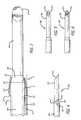
- FIG. 1is a side elevation view of an instrument set having a cannula and stylet in accordance with one embodiment of the present invention.
- FIG. 2is an enlarged partial side elevation view of a distal end of the instrument set of FIG. 1 along line 2 of FIG. 1 .
- FIG. 3is a partial cross-sectional side view of the distal end of the cannula of FIG. 1 with the stylet of FIG. 1 .
- FIG. 4is a partial side elevation view of the distal end of the stylet of FIG. 1 .
- FIG. 5is a partial side elevation view of the distal end of a stylet in accordance with another preferred embodiment of the present invention.
- FIG. 6is a partial side elevation view of the stylet of FIG. 5 rotated approximately 90 degrees.
- FIG. 7is a partial side elevation view of a distal end of an instrument set having a cannula and stylet in accordance with another preferred embodiment of the present invention.
- FIG. 8is a partial cross-sectional side view of the distal end of the cannula of FIG. 7 and stylet of FIG. 1 .
- FIG. 9is a partial side elevation view of a distal end of an instrument set having a cannula and stylet in accordance with another preferred embodiment of the present invention.
- FIGS. 1-3illustrate an instrument set in accordance with one preferred embodiment of the present invention.
- the instrument setincludes a cannula and a stylet insertable at least in part into the cannula, the cannula and stylet each having a generally matching tapered profile adapted to facilitate insertion of the instrument set into the tissue of a patient, preferably into the bone of a patient.
- the tapered profile of the instruments set forth belowmay be adapted for use with other sets having two or more instruments.
- cannula 100is adapted to receive at least a portion of a stylet 200 therethrough.
- Cannula 100includes a body 102 , and exterior surface 104 , a distal end 106 , and a passage 108 having an interior surface 110 .
- Cannula 100also includes a window 112 proximate distal end 106 .
- Window 112is preferably sized and configured to permit the passage of a portion an instrument such as a bone displacement instrument therethrough.
- Distal end 106 of cannula 100includes an outer perimeter 114 having a distal edge 116 and may include a plurality of longitudinal serrations, grooves, or scallops 118 .
- Serrations 118cut into bone similar to a serrated knife.
- Serrations 118preserve the strength of distal end 106 because they permit the wall of cannula 100 to retain a thickness sufficient to ensure that the distal end remains rigid while at the same time facilitates the insertion of cannula 100 into the surrounding tissue and bone.
- outer perimeter 114is preferably tapered relative to the mid-longitudinal axis of cannula 100 .
- the tapered portion of distal end 106preferably includes two angled portions 120 and 122 , but may include only one larger angled portion.
- the first angled portion 120is preferably at an angle A relative to the mid-longitudinal axis of cannula 100 .
- a preferred range for angle Ais between 0 to 30 degrees relative to the mid-longitudinal axis of cannula 100 .
- the second angled portion 122is preferably at an angle B relative to the mid-longitudinal axis of cannula 100 .
- a preferred range for angle Bis between 0 to 30 degrees relative to the mid-longitudinal axis of cannula 100 .
- angled portions 120 , 122form a tapered profile generally in the range of 5 to 45 degrees, more preferably 10 to 45 degrees, and most preferably 15 degrees relative to the mid-longitudinal axis of cannula 100 .
- outer perimeter 114may have a single, continuous taper to distal edge 116 , or more than two angled portions. It will be further appreciated that outer perimeter 114 may be curved in a plane parallel with the mid-longitudinal axis of the cannula so as to approximate the shape of a spherical or elongated dome.
- stylet 200includes a shaft 202 and a distal end 204 .
- Shaft 202includes a proximal portion 206 , a transition portion 208 , and a distal portion 210 having a bevel 212 at distal end 204 .
- Portion 210preferably has a reduced dimension to facilitate introduction into the tissue in a manner similar to that of a guide wire.
- transition 208is a tapered portion of shaft 202 that converges distally toward the mid-longitudinal axis of stylet 200 to provide a transition from a larger dimension of proximal portion 206 to a smaller dimension of distal portion 210 of shaft 202 .
- transition 208is at an angle C relative to the mid-longitudinal axis of stylet 200 .
- Angle Cis preferably in the range of 5 to 45 degrees, more preferably 10 to 45 degrees, and most preferably 14 degrees relative to the mid-longitudinal axis of stylet 200 .
- passage 108 of cannula 100has a reduced portion proximate distal end 106 of cannula 100 that is sized and configured to have a transverse cross sectional dimension less than the transverse cross sectional dimension of proximal portion 206 of stylet 200 .
- the reduced portion of passage 108prevents stylet 200 from extending more than a predetermined distance beyond distal edge 116 of cannula 100 by preventing the larger dimension of proximal portion 206 of shaft 202 to pass therethrough.
- angle C of transition 208 of stylet 200is at an angle that is between angles A and B of cannula 100 . It will be appreciated by those of ordinary skill in the art that the angles of distal end 106 of cannula 100 and of transition 208 of stylet 200 may be varied without departing from the scope of the present invention.
- the angle of the over-all tapered profiled of outer perimeter 114 and the angle of transition 208are each preferably within 15 degrees of each other, more preferably within 5 degrees of each other, and most preferably the same or approximately the same angle.
- distal edge 116 of cannula 100is adjacent transition 208 preferably between proximal and distal longitudinal limits 207 , 209 of transition 208 , both longitudinally and along the radial height of transition 208 .
- distal edge 116is closer to distal longitudinal limit 209 of transition 208 more than proximal longitudinal limit 207 of transition 208 . It will be appreciated that distal edge 116 may extend before or after the longitudinal limits of transition 208 when the cannula and stylet are assembled to present a smooth transition without departing from the scope of the present invention.
- a surgeongrasps the handle of stylet 200 (shown in FIG. 1 ) and places stylet 200 into cannula 100 with at least a portion of transition 208 and distal end 204 of stylet 200 extending beyond distal end 104 of cannula 100 .
- the handles of the instrumentsmay be configured to lock to one another.
- the surgeonthen inserts distal end 204 of stylet 200 into the tissue such as the bone of the patient and continues advancing stylet 200 , along with cannula 100 , into the bone to form an opening into the bone.
- cannula 100may be moved relative to stylet 200 and further advanced into the bone using stylet 200 as a guide wire.
- Stylet 200may be withdrawn either partially or completely from cannula 100 with cannula 100 remaining in the bone.
- Cannula 100may be further advanced into the bone after the withdrawal of stylet 200 if desired.
- the instrument setis preferably inserted to a depth sufficient to permit a surgeon to access bone through window 112 .
- the surgeonmay insert other instruments through cannula 100 , such as an instrument to displace bone through window 112 .
- Cannula 100may also be used to introduce a material therethrough.
- materialsinclude a flowable material such as bone cement; other therapeutic materials such as bone morphogenetic protein, hydroxyapatite, hydroxyapatite tricalcium phosphate, or an anti-microbial substance; or a relatively solid and/or artificial material such as an implant.
- a flowable materialsuch as bone cement
- other therapeutic materialssuch as bone morphogenetic protein, hydroxyapatite, hydroxyapatite tricalcium phosphate, or an anti-microbial substance
- a relatively solid and/or artificial materialsuch as an implant.
- the methodis preferably performed in the spine of a human patient. It will be recognized that the instrument set and method of the present invention may be used in other areas of the human body.
- Cannula 100 and stylet 200are made of a surgical grade material.
- suitable materialsinclude, but are not limited to, metal such as stainless steel and titanium, nitinol, carbon composites, and a plastic polymer. It will be appreciated that cannula 100 and stylet 200 may be made of any combination of metal, plastic, carbon composite, nitinol, or other material suitable for the intended purpose.
- cannula 100has a maximum length along the mid-longitudinal axis of the cannula that is approximately 5.1 inches between the distal end and the handle.
- the thickness of the wall of the cannulais preferably approximately 0.015 inches.
- the maximum transverse dimension at distal end 106 of cannula 100is preferably approximately 0.1 inches.
- the length of the tapered portion of distal end 106is preferably generally 0.013 inches between the furthest distal extent of window 112 to distal edge 116 . It will be appreciated that the dimensions set forth above may be varied without departing from the scope of the present invention.
- Stylet 200preferably has a length along the mid-longitudinal axis of approximately 6.1 inches between the handle and distal end 204 .
- distal portion 210 of stylet 200preferably has a length from the tip of distal end 204 to transition 208 that is greater than the length of transition 208 , but less than the length of window 112 of cannula 100 .
- distal portion 210 of stylet 200has a length of approximately 0.5 inches. It will be appreciated that the dimensions set forth above may be varied without departing from the scope of the present invention.
- Stylet 300is similar to stylet 200 except that distal end 304 includes a plurality of facets 312 , 314 . It will be appreciated by those of ordinary skill in the art that the number and configuration of the facets may be varied without departing from the scope of the present invention.
- stylet 300preferably includes a plurality of facets 312 , 314 at an angle to each other.
- a third facetextends on another side to form a tri-faceted configuration at distal end 304 of style 300 .
- a cannula in accordance with another preferred embodiment of the present inventionis shown and generally referred to by the reference number 400 .
- a cannula 400is similar to cannula 100 except that distal edge 416 of cannula 400 forms a sharp edge.
- outer perimeter 414has an angled portion at an angle D which is preferably in the range of 10 to 45 degrees relative to the mid-longitudinal axis of cannula 400 .
- Angle Dhas a steeper angle as compared to angle B shown in FIG. 3 .
- the configuration shown in FIG. 8permits a smoother transition 426 between distal edge 416 of cannula 400 and transition 208 of stylet 200 .
- the nearly seamless transition 426further facilitates insertion of the instrument set into the surrounding tissues of the patient at least in part due to the reduction of the surface profile of the leading end of the cannula.
- a cannula in accordance with another preferred embodiment of the present inventionis shown and generally referred to by the reference number 500 .
- Cannula 500is similar to cannula 100 except that body 502 includes a thread 528 proximate the distal end.
- Thread 528is configured such that once the instrument set is partially inserted into the patient to a depth where thread 528 contacts bone, the surgeon may rotate cannula 500 about the mid-longitudinal axis and threadably secure cannula 500 to one or more bones of the patient.
- Thread 528has a low profile thread height to allow cannula 500 to slide into tissue without significant engagement of the thread with the surrounding tissue.
- the furthest extent of thread 528 as measured along the mid-longitudinal axis of cannula 500is preferably less than the maximum longitudinal extent of the tapered distal end portion of cannula 500 .
- thread 528may be configured and placed along the length of cannula 500 in a manner sufficient for the intended purpose of cannula 500 .
- thread 528is preferably configured to engage a pedicle of a vertebra of a human spine.
- a preferred method for using the instrument set shown in FIG. 9includes inserting by linear insertion the instrument set at least partially into the patient through a portion of bone and tissue; inserting the set to a depth until thread 528 contacts a portion of bone, such as a pedicle of a human spine; rotating cannula 500 about its mid-longitudinal axis to engage thread 528 within a portion of bone; and withdrawing stylet 200 from cannula 500 . Once the procedure has been completed through cannula 500 , cannula 500 is then rotated in the opposite direction of insertion to disengage cannula 500 from the bone of the patient.
- cannula 100could be a sheath, sleeve, retractor, or any other tubular or cannulated member.
- Instrument 200could be a stylet, obdurator, trocar, bone tamp, forceps, or any other instrument insertable in a tube having a portion adapted to extend beyond the distal end of the tube.
- Advantages of the present inventioninclude, for example, the ability of the user to more precisely place the instrument set within the patient.
- the tapered configuration of the present inventionhas the advantage of minimizing disruption of surrounding tissues and bone as the instrument set is being inserted into the patient.
- the tapered configuration of the cannulaadvantageously functions as a depth stop to the stylet to keep the distal end of the stylet from extending too far beyond the distal end of the cannula.
- An advantage of the longitudinal serrations at the distal end of the cannulais that the serrations facilitate insertion similar to a serrated knife to permit a more precise placement of the instrument set within the patient.
- An advantage of the thread shown in FIG. 9is that the surgeon is able to attach the cannula to the patient to provide a more stable base for subsequent use of instruments through the cannula.
- distal portion 210 of shaft 202 of stylet 200may be tapered along its length and may, if desired, have an angle substantially matching or precisely matching that of transition 208 to create an elongated taper.
- cannula 100 and stylet 200need not have a circular cross section, but may have any other type of cross section suitable for the intended purpose.
- the cross section of either instrumentmay be that of an elongated oval or other non-circular shape such as a square, or a shaft with a keel to prevent the inner instrument from rotating within the cannula.
Landscapes
- Health & Medical Sciences (AREA)
- Surgery (AREA)
- Life Sciences & Earth Sciences (AREA)
- Heart & Thoracic Surgery (AREA)
- Molecular Biology (AREA)
- Pathology (AREA)
- Engineering & Computer Science (AREA)
- Biomedical Technology (AREA)
- Veterinary Medicine (AREA)
- Medical Informatics (AREA)
- Nuclear Medicine, Radiotherapy & Molecular Imaging (AREA)
- Animal Behavior & Ethology (AREA)
- General Health & Medical Sciences (AREA)
- Public Health (AREA)
- Orthopedic Medicine & Surgery (AREA)
- Surgical Instruments (AREA)
- Media Introduction/Drainage Providing Device (AREA)
Abstract
Description
Claims (24)
Priority Applications (3)
| Application Number | Priority Date | Filing Date | Title |
|---|---|---|---|
| US11/412,342US7892207B2 (en) | 2006-04-27 | 2006-04-27 | Dilating stylet and cannula |
| PCT/US2007/066917WO2007127655A2 (en) | 2006-04-27 | 2007-04-19 | Dilating stylet and cannula |
| US13/028,560US9066753B2 (en) | 2006-04-27 | 2011-02-16 | Dilating stylet and cannula |
Applications Claiming Priority (1)
| Application Number | Priority Date | Filing Date | Title |
|---|---|---|---|
| US11/412,342US7892207B2 (en) | 2006-04-27 | 2006-04-27 | Dilating stylet and cannula |
Related Child Applications (1)
| Application Number | Title | Priority Date | Filing Date |
|---|---|---|---|
| US13/028,560DivisionUS9066753B2 (en) | 2006-04-27 | 2011-02-16 | Dilating stylet and cannula |
Publications (2)
| Publication Number | Publication Date |
|---|---|
| US20070255282A1 US20070255282A1 (en) | 2007-11-01 |
| US7892207B2true US7892207B2 (en) | 2011-02-22 |
Family
ID=38474105
Family Applications (2)
| Application Number | Title | Priority Date | Filing Date |
|---|---|---|---|
| US11/412,342Expired - Fee RelatedUS7892207B2 (en) | 2006-04-27 | 2006-04-27 | Dilating stylet and cannula |
| US13/028,560Expired - Fee RelatedUS9066753B2 (en) | 2006-04-27 | 2011-02-16 | Dilating stylet and cannula |
Family Applications After (1)
| Application Number | Title | Priority Date | Filing Date |
|---|---|---|---|
| US13/028,560Expired - Fee RelatedUS9066753B2 (en) | 2006-04-27 | 2011-02-16 | Dilating stylet and cannula |
Country Status (2)
| Country | Link |
|---|---|
| US (2) | US7892207B2 (en) |
| WO (1) | WO2007127655A2 (en) |
Cited By (12)
| Publication number | Priority date | Publication date | Assignee | Title |
|---|---|---|---|---|
| US9186484B2 (en) | 2010-07-01 | 2015-11-17 | DePuy Synthes Products, Inc. | Guidewire insertion methods and devices |
| US9226756B2 (en) | 2012-05-14 | 2016-01-05 | DePuy Synthes Products, Inc. | Bone access instrument |
| US9289249B2 (en) | 2013-03-14 | 2016-03-22 | DePuy Synthes Products, Inc. | Bone anchors and surgical instruments with integrated guide tips |
| US20170055964A1 (en)* | 2015-08-28 | 2017-03-02 | SiteSelect Inc. | Incision expansion introducer |
| US9855087B2 (en) | 2014-08-04 | 2018-01-02 | DePuy Synthes Products, LLC | Methods and devices for spinal screw insertion |
| USD816830S1 (en) | 2013-04-30 | 2018-05-01 | Avent, Inc. | Catheter tube |
| US10251630B2 (en) | 2015-08-28 | 2019-04-09 | SiteSelect Inc. | Tissue excision device with anchor stability rod and anchor stability rod |
| US10433883B2 (en) | 2017-06-27 | 2019-10-08 | Medos International Sarl | Spinal screw insertion devices and methods |
| US10779872B2 (en) | 2017-11-02 | 2020-09-22 | Medos International Sarl | Bone anchor insertion instruments and methods |
| US11123113B2 (en) | 2019-06-13 | 2021-09-21 | Medos International Sarl | Screw inserter instruments and methods |
| US11224472B2 (en) | 2019-06-13 | 2022-01-18 | Medos International Sarl | Screw inserter instruments and methods |
| US11246637B2 (en) | 2020-05-11 | 2022-02-15 | Alphatec Spine, Inc. | Stimulating targeting needle |
Families Citing this family (70)
| Publication number | Priority date | Publication date | Assignee | Title |
|---|---|---|---|---|
| ES2545328T3 (en) | 2003-03-14 | 2015-09-10 | Depuy Spine, Inc. | Bone cement hydraulic injection device in percutaneous vertebroplasty |
| US8066713B2 (en) | 2003-03-31 | 2011-11-29 | Depuy Spine, Inc. | Remotely-activated vertebroplasty injection device |
| US8415407B2 (en) | 2004-03-21 | 2013-04-09 | Depuy Spine, Inc. | Methods, materials, and apparatus for treating bone and other tissue |
| US8579908B2 (en) | 2003-09-26 | 2013-11-12 | DePuy Synthes Products, LLC. | Device for delivering viscous material |
| CN101065080B (en) | 2004-07-30 | 2021-10-29 | 德普伊新特斯产品有限责任公司 | Materials and Instruments for Manipulating Bone and Other Tissues |
| US7905904B2 (en) | 2006-02-03 | 2011-03-15 | Biomet Sports Medicine, Llc | Soft tissue repair device and associated methods |
| US8088130B2 (en) | 2006-02-03 | 2012-01-03 | Biomet Sports Medicine, Llc | Method and apparatus for coupling soft tissue to a bone |
| US8298262B2 (en) | 2006-02-03 | 2012-10-30 | Biomet Sports Medicine, Llc | Method for tissue fixation |
| US8128658B2 (en) | 2004-11-05 | 2012-03-06 | Biomet Sports Medicine, Llc | Method and apparatus for coupling soft tissue to bone |
| US9017381B2 (en) | 2007-04-10 | 2015-04-28 | Biomet Sports Medicine, Llc | Adjustable knotless loops |
| US8303604B2 (en) | 2004-11-05 | 2012-11-06 | Biomet Sports Medicine, Llc | Soft tissue repair device and method |
| US7909851B2 (en) | 2006-02-03 | 2011-03-22 | Biomet Sports Medicine, Llc | Soft tissue repair device and associated methods |
| US7749250B2 (en) | 2006-02-03 | 2010-07-06 | Biomet Sports Medicine, Llc | Soft tissue repair assembly and associated method |
| US8137382B2 (en) | 2004-11-05 | 2012-03-20 | Biomet Sports Medicine, Llc | Method and apparatus for coupling anatomical features |
| US8361113B2 (en) | 2006-02-03 | 2013-01-29 | Biomet Sports Medicine, Llc | Method and apparatus for coupling soft tissue to a bone |
| US7658751B2 (en) | 2006-09-29 | 2010-02-09 | Biomet Sports Medicine, Llc | Method for implanting soft tissue |
| US9801708B2 (en) | 2004-11-05 | 2017-10-31 | Biomet Sports Medicine, Llc | Method and apparatus for coupling soft tissue to a bone |
| US8118836B2 (en) | 2004-11-05 | 2012-02-21 | Biomet Sports Medicine, Llc | Method and apparatus for coupling soft tissue to a bone |
| US9381024B2 (en) | 2005-07-31 | 2016-07-05 | DePuy Synthes Products, Inc. | Marked tools |
| US9918767B2 (en) | 2005-08-01 | 2018-03-20 | DePuy Synthes Products, Inc. | Temperature control system |
| US8360629B2 (en) | 2005-11-22 | 2013-01-29 | Depuy Spine, Inc. | Mixing apparatus having central and planetary mixing elements |
| US9149267B2 (en) | 2006-02-03 | 2015-10-06 | Biomet Sports Medicine, Llc | Method and apparatus for coupling soft tissue to a bone |
| US8652171B2 (en) | 2006-02-03 | 2014-02-18 | Biomet Sports Medicine, Llc | Method and apparatus for soft tissue fixation |
| US9538998B2 (en) | 2006-02-03 | 2017-01-10 | Biomet Sports Medicine, Llc | Method and apparatus for fracture fixation |
| US8968364B2 (en) | 2006-02-03 | 2015-03-03 | Biomet Sports Medicine, Llc | Method and apparatus for fixation of an ACL graft |
| US8562645B2 (en) | 2006-09-29 | 2013-10-22 | Biomet Sports Medicine, Llc | Method and apparatus for forming a self-locking adjustable loop |
| US9078644B2 (en) | 2006-09-29 | 2015-07-14 | Biomet Sports Medicine, Llc | Fracture fixation device |
| US11259792B2 (en) | 2006-02-03 | 2022-03-01 | Biomet Sports Medicine, Llc | Method and apparatus for coupling anatomical features |
| US8652172B2 (en) | 2006-02-03 | 2014-02-18 | Biomet Sports Medicine, Llc | Flexible anchors for tissue fixation |
| US10517587B2 (en) | 2006-02-03 | 2019-12-31 | Biomet Sports Medicine, Llc | Method and apparatus for forming a self-locking adjustable loop |
| US11311287B2 (en) | 2006-02-03 | 2022-04-26 | Biomet Sports Medicine, Llc | Method for tissue fixation |
| US8597327B2 (en) | 2006-02-03 | 2013-12-03 | Biomet Manufacturing, Llc | Method and apparatus for sternal closure |
| US9468433B2 (en) | 2006-02-03 | 2016-10-18 | Biomet Sports Medicine, Llc | Method and apparatus for forming a self-locking adjustable loop |
| US8801783B2 (en) | 2006-09-29 | 2014-08-12 | Biomet Sports Medicine, Llc | Prosthetic ligament system for knee joint |
| US8562647B2 (en) | 2006-09-29 | 2013-10-22 | Biomet Sports Medicine, Llc | Method and apparatus for securing soft tissue to bone |
| US7892207B2 (en)* | 2006-04-27 | 2011-02-22 | Warsaw Orthopedic, Inc. | Dilating stylet and cannula |
| US7905884B2 (en)* | 2006-04-27 | 2011-03-15 | Warsaw Orthopedic, Inc. | Method for use of dilating stylet and cannula |
| US7842038B2 (en) | 2006-05-04 | 2010-11-30 | Warsaw Orthopedic, Inc. | Method for using retractable stylet and cannula combination to form an opening in bone |
| US8167899B2 (en)* | 2006-05-04 | 2012-05-01 | Warsaw Orthopedic, Inc. | Retractable stylet and cannula combination |
| US20100069786A1 (en)* | 2006-06-29 | 2010-03-18 | Depuy Spine, Inc. | Integrated bone biopsy and therapy apparatus |
| AU2007297097A1 (en) | 2006-09-14 | 2008-03-20 | Depuy Spine, Inc. | Bone cement and methods of use thereof |
| US8672969B2 (en) | 2006-09-29 | 2014-03-18 | Biomet Sports Medicine, Llc | Fracture fixation device |
| US9918826B2 (en) | 2006-09-29 | 2018-03-20 | Biomet Sports Medicine, Llc | Scaffold for spring ligament repair |
| US11259794B2 (en) | 2006-09-29 | 2022-03-01 | Biomet Sports Medicine, Llc | Method for implanting soft tissue |
| US8950929B2 (en)* | 2006-10-19 | 2015-02-10 | DePuy Synthes Products, LLC | Fluid delivery system |
| FR2929502B1 (en)* | 2008-04-04 | 2011-04-08 | Clariance | NUCLEIC IMPLANT. |
| US12245759B2 (en) | 2008-08-22 | 2025-03-11 | Biomet Sports Medicine, Llc | Method and apparatus for coupling soft tissue to bone |
| US12419632B2 (en) | 2008-08-22 | 2025-09-23 | Biomet Sports Medicine, Llc | Method and apparatus for coupling anatomical features |
| US8702677B2 (en)* | 2008-10-31 | 2014-04-22 | Warsaw Orthopedic, Inc. | Device and method for directional delivery of a drug depot |
| US12096928B2 (en) | 2009-05-29 | 2024-09-24 | Biomet Sports Medicine, Llc | Method and apparatus for coupling soft tissue to a bone |
| US8715223B2 (en)* | 2009-07-22 | 2014-05-06 | Warsaw Orthopedic, Inc. | Device and method for delivery of a drug depot near the nerve |
| US12329373B2 (en) | 2011-05-02 | 2025-06-17 | Biomet Sports Medicine, Llc | Method and apparatus for soft tissue fixation |
| US9357991B2 (en) | 2011-11-03 | 2016-06-07 | Biomet Sports Medicine, Llc | Method and apparatus for stitching tendons |
| US9381013B2 (en) | 2011-11-10 | 2016-07-05 | Biomet Sports Medicine, Llc | Method for coupling soft tissue to a bone |
| US9314241B2 (en) | 2011-11-10 | 2016-04-19 | Biomet Sports Medicine, Llc | Apparatus for coupling soft tissue to a bone |
| ES2656974T3 (en)* | 2012-01-19 | 2018-03-01 | Stryker European Holdings I, Llc | Cuff for suprarrotulian surgery |
| US9918827B2 (en) | 2013-03-14 | 2018-03-20 | Biomet Sports Medicine, Llc | Scaffold for spring ligament repair |
| US20150100077A1 (en)* | 2013-10-09 | 2015-04-09 | Safewire, LLC | Thread forming jamshidi assembly |
| CN105078551A (en)* | 2014-05-14 | 2015-11-25 | 兰州大学第一医院 | Bone marrow puncture needle |
| US9775978B2 (en) | 2014-07-25 | 2017-10-03 | Warsaw Orthopedic, Inc. | Drug delivery device and methods having a retaining member |
| US10080877B2 (en) | 2014-07-25 | 2018-09-25 | Warsaw Orthopedic, Inc. | Drug delivery device and methods having a drug cartridge |
| US10076650B2 (en) | 2015-11-23 | 2018-09-18 | Warsaw Orthopedic, Inc. | Enhanced stylet for drug depot injector |
| USD802756S1 (en) | 2016-06-23 | 2017-11-14 | Warsaw Orthopedic, Inc. | Drug pellet cartridge |
| EP3528723B1 (en) | 2016-10-27 | 2023-08-16 | C. R. Bard, Inc. | Intraosseous access device |
| US10434261B2 (en) | 2016-11-08 | 2019-10-08 | Warsaw Orthopedic, Inc. | Drug pellet delivery system and method |
| US11839403B2 (en) | 2017-02-06 | 2023-12-12 | Distal Access, Llc | Tissue piercing assemblies |
| EP3576636A4 (en)* | 2017-02-06 | 2020-12-09 | Distal Access, LLC | Tissue piercing assemblies |
| WO2021062215A1 (en)* | 2019-09-27 | 2021-04-01 | Bard Access Systems, Inc. | Step needle for intraosseous access device |
| CN113317840A (en) | 2020-02-28 | 2021-08-31 | 巴德阿克塞斯系统股份有限公司 | Flexible intra-osseous obturator |
| CN216167681U (en) | 2020-07-17 | 2022-04-05 | 巴德阿克塞斯系统股份有限公司 | Safety mechanism |
Citations (26)
| Publication number | Priority date | Publication date | Assignee | Title |
|---|---|---|---|---|
| US3994287A (en) | 1974-07-01 | 1976-11-30 | Centre De Recherche Industrielle Du Quebec | Trocar |
| DE2906054A1 (en) | 1978-12-19 | 1980-06-26 | Synthes Ag | DEVICE FOR MAKING A HOLE IN A BONE |
| US4793363A (en) | 1986-09-11 | 1988-12-27 | Sherwood Medical Company | Biopsy needle |
| US4838282A (en) | 1987-02-26 | 1989-06-13 | Manan Manufacturing Co., Inc. | Bone biopsy needle assembly |
| DE9007115U1 (en) | 1990-06-27 | 1990-08-30 | Richard Wolf Gmbh, 75438 Knittlingen | Trocar sleeve |
| US5257632A (en) | 1992-09-09 | 1993-11-02 | Symbiosis Corporation | Coaxial bone marrow biopsy coring and aspirating needle assembly and method of use thereof |
| US5263937A (en) | 1993-02-11 | 1993-11-23 | Shipp John I | Trocar with profile to reduce insertion force |
| US5295974A (en) | 1991-01-07 | 1994-03-22 | Laughlin D Michael O | Shielded hypodermic needle with I.V. cannula |
| US5772661A (en) | 1988-06-13 | 1998-06-30 | Michelson; Gary Karlin | Methods and instrumentation for the surgical correction of human thoracic and lumbar spinal disease from the antero-lateral aspect of the spine |
| US5868684A (en) | 1993-12-22 | 1999-02-09 | Radi Medical Systems Ab | Device for hard tissue biopsy sampling |
| US5957832A (en) | 1993-10-08 | 1999-09-28 | Heartport, Inc. | Stereoscopic percutaneous visualization system |
| US6019776A (en) | 1997-10-14 | 2000-02-01 | Parallax Medical, Inc. | Precision depth guided instruments for use in vertebroplasty |
| US6080155A (en) | 1988-06-13 | 2000-06-27 | Michelson; Gary Karlin | Method of inserting and preloading spinal implants |
| US6224607B1 (en) | 1999-01-25 | 2001-05-01 | Gary K. Michelson | Instrumentation and method for creating an intervertebral space for receiving an implant |
| US6264618B1 (en) | 1999-01-28 | 2001-07-24 | Minrad, Inc. | Sampling device and method of retrieving a sample |
| US6325812B1 (en) | 1993-03-05 | 2001-12-04 | Innerdyne, Inc. | Trocar system having expandable port |
| US20020177897A1 (en) | 2001-02-04 | 2002-11-28 | Michelson Gary K. | Instrumentation and method for inserting and deploying and expandable interbody spinal fusion implant |
| US20030018309A1 (en) | 2001-07-17 | 2003-01-23 | Breznock Eugene Michael | Method and apparatus for chest drainage |
| US6554778B1 (en) | 2001-01-26 | 2003-04-29 | Manan Medical Products, Inc. | Biopsy device with removable handle |
| US6582439B1 (en) | 2001-12-28 | 2003-06-24 | Yacmur Llc | Vertebroplasty system |
| US20030191414A1 (en) | 1999-10-19 | 2003-10-09 | Kyphon Inc. | Hand-held instruments that access interior body regions |
| US6641564B1 (en) | 2000-11-06 | 2003-11-04 | Medamicus, Inc. | Safety introducer apparatus and method therefor |
| US20030236506A1 (en) | 2002-06-20 | 2003-12-25 | Eric Schofield | Dual outside diameter cannula for insertion into bone |
| US20040249306A1 (en)* | 2003-06-03 | 2004-12-09 | Islam Abul Bashar Mohammed Anwarul | Bone marrow biopsy needle |
| DE102004024188A1 (en) | 2004-03-16 | 2006-02-16 | Wolfram Schnepp-Pesch | Locating device for bio compatible fabric structures in animal or human bodies, has circular curvature defined at frontmost area of needle to assist needle feed out from air lock tube |
| US20070255281A1 (en) | 2006-04-27 | 2007-11-01 | Sdgi Holdings, Inc. | Method for use of dilating stylet and cannula |
Family Cites Families (5)
| Publication number | Priority date | Publication date | Assignee | Title |
|---|---|---|---|---|
| US130759A (en)* | 1872-08-20 | Improvement in feed-water heaters for locomotives | ||
| US2919692A (en)* | 1956-02-23 | 1960-01-05 | Ackermann Wolfgang | Vertebral trephine biopsy instruments |
| US3628524A (en)* | 1969-02-28 | 1971-12-21 | Khosrow Jamshidi | Biopsy needle |
| US6679886B2 (en)* | 2000-09-01 | 2004-01-20 | Synthes (Usa) | Tools and methods for creating cavities in bone |
| US7892207B2 (en)* | 2006-04-27 | 2011-02-22 | Warsaw Orthopedic, Inc. | Dilating stylet and cannula |
- 2006
- 2006-04-27USUS11/412,342patent/US7892207B2/ennot_activeExpired - Fee Related
- 2007
- 2007-04-19WOPCT/US2007/066917patent/WO2007127655A2/enactiveApplication Filing
- 2011
- 2011-02-16USUS13/028,560patent/US9066753B2/ennot_activeExpired - Fee Related
Patent Citations (28)
| Publication number | Priority date | Publication date | Assignee | Title |
|---|---|---|---|---|
| US3994287A (en) | 1974-07-01 | 1976-11-30 | Centre De Recherche Industrielle Du Quebec | Trocar |
| DE2906054A1 (en) | 1978-12-19 | 1980-06-26 | Synthes Ag | DEVICE FOR MAKING A HOLE IN A BONE |
| US4793363A (en) | 1986-09-11 | 1988-12-27 | Sherwood Medical Company | Biopsy needle |
| US4838282A (en) | 1987-02-26 | 1989-06-13 | Manan Manufacturing Co., Inc. | Bone biopsy needle assembly |
| US5772661A (en) | 1988-06-13 | 1998-06-30 | Michelson; Gary Karlin | Methods and instrumentation for the surgical correction of human thoracic and lumbar spinal disease from the antero-lateral aspect of the spine |
| US6080155A (en) | 1988-06-13 | 2000-06-27 | Michelson; Gary Karlin | Method of inserting and preloading spinal implants |
| DE9007115U1 (en) | 1990-06-27 | 1990-08-30 | Richard Wolf Gmbh, 75438 Knittlingen | Trocar sleeve |
| US5295974A (en) | 1991-01-07 | 1994-03-22 | Laughlin D Michael O | Shielded hypodermic needle with I.V. cannula |
| US5257632A (en) | 1992-09-09 | 1993-11-02 | Symbiosis Corporation | Coaxial bone marrow biopsy coring and aspirating needle assembly and method of use thereof |
| US5385151A (en) | 1992-09-09 | 1995-01-31 | Symbiosis Corporation | Coaxial bone marrow biopsy needle assembly |
| US5263937A (en) | 1993-02-11 | 1993-11-23 | Shipp John I | Trocar with profile to reduce insertion force |
| US6325812B1 (en) | 1993-03-05 | 2001-12-04 | Innerdyne, Inc. | Trocar system having expandable port |
| US5957832A (en) | 1993-10-08 | 1999-09-28 | Heartport, Inc. | Stereoscopic percutaneous visualization system |
| US5868684A (en) | 1993-12-22 | 1999-02-09 | Radi Medical Systems Ab | Device for hard tissue biopsy sampling |
| US6019776A (en) | 1997-10-14 | 2000-02-01 | Parallax Medical, Inc. | Precision depth guided instruments for use in vertebroplasty |
| US6224607B1 (en) | 1999-01-25 | 2001-05-01 | Gary K. Michelson | Instrumentation and method for creating an intervertebral space for receiving an implant |
| US6264618B1 (en) | 1999-01-28 | 2001-07-24 | Minrad, Inc. | Sampling device and method of retrieving a sample |
| US20030191414A1 (en) | 1999-10-19 | 2003-10-09 | Kyphon Inc. | Hand-held instruments that access interior body regions |
| US6641564B1 (en) | 2000-11-06 | 2003-11-04 | Medamicus, Inc. | Safety introducer apparatus and method therefor |
| US6554778B1 (en) | 2001-01-26 | 2003-04-29 | Manan Medical Products, Inc. | Biopsy device with removable handle |
| US20020177897A1 (en) | 2001-02-04 | 2002-11-28 | Michelson Gary K. | Instrumentation and method for inserting and deploying and expandable interbody spinal fusion implant |
| US20030018309A1 (en) | 2001-07-17 | 2003-01-23 | Breznock Eugene Michael | Method and apparatus for chest drainage |
| US6638253B2 (en)* | 2001-07-17 | 2003-10-28 | Eugene Michael Breznock | Method and apparatus for chest drainage |
| US6582439B1 (en) | 2001-12-28 | 2003-06-24 | Yacmur Llc | Vertebroplasty system |
| US20030236506A1 (en) | 2002-06-20 | 2003-12-25 | Eric Schofield | Dual outside diameter cannula for insertion into bone |
| US20040249306A1 (en)* | 2003-06-03 | 2004-12-09 | Islam Abul Bashar Mohammed Anwarul | Bone marrow biopsy needle |
| DE102004024188A1 (en) | 2004-03-16 | 2006-02-16 | Wolfram Schnepp-Pesch | Locating device for bio compatible fabric structures in animal or human bodies, has circular curvature defined at frontmost area of needle to assist needle feed out from air lock tube |
| US20070255281A1 (en) | 2006-04-27 | 2007-11-01 | Sdgi Holdings, Inc. | Method for use of dilating stylet and cannula |
Cited By (23)
| Publication number | Priority date | Publication date | Assignee | Title |
|---|---|---|---|---|
| US9186484B2 (en) | 2010-07-01 | 2015-11-17 | DePuy Synthes Products, Inc. | Guidewire insertion methods and devices |
| US9788843B2 (en) | 2012-05-14 | 2017-10-17 | DePuy Synthes Products, Inc. | Bone access instrument |
| US9226756B2 (en) | 2012-05-14 | 2016-01-05 | DePuy Synthes Products, Inc. | Bone access instrument |
| US10413339B2 (en) | 2013-03-14 | 2019-09-17 | DePuy Synthes Products, Inc. | Bone anchors and surgical instruments with integrated guide tips |
| US9433445B2 (en) | 2013-03-14 | 2016-09-06 | DePuy Synthes Products, Inc. | Bone anchors and surgical instruments with integrated guide tips |
| US11457961B2 (en) | 2013-03-14 | 2022-10-04 | DePuy Synthes Products, Inc. | Bone anchors and surgical instruments with integrated guide tips |
| US9289249B2 (en) | 2013-03-14 | 2016-03-22 | DePuy Synthes Products, Inc. | Bone anchors and surgical instruments with integrated guide tips |
| US11937857B2 (en) | 2013-03-14 | 2024-03-26 | DePuy Synthes Products, Inc. | Bone anchors and surgical instruments with integrated guide tips |
| USD816830S1 (en) | 2013-04-30 | 2018-05-01 | Avent, Inc. | Catheter tube |
| US9855087B2 (en) | 2014-08-04 | 2018-01-02 | DePuy Synthes Products, LLC | Methods and devices for spinal screw insertion |
| US10568677B2 (en) | 2014-08-04 | 2020-02-25 | DePuy Synthes Products, Inc. | Methods and devices for spinal screw insertion |
| US11642158B2 (en) | 2014-08-04 | 2023-05-09 | DePuy Synthes Products, Inc. | Methods and devices for spinal screw insertion |
| US20170055964A1 (en)* | 2015-08-28 | 2017-03-02 | SiteSelect Inc. | Incision expansion introducer |
| US10251630B2 (en) | 2015-08-28 | 2019-04-09 | SiteSelect Inc. | Tissue excision device with anchor stability rod and anchor stability rod |
| US10433883B2 (en) | 2017-06-27 | 2019-10-08 | Medos International Sarl | Spinal screw insertion devices and methods |
| US11648038B2 (en) | 2017-06-27 | 2023-05-16 | Medos International Sarl | Spinal screw insertion devices and methods |
| US10779872B2 (en) | 2017-11-02 | 2020-09-22 | Medos International Sarl | Bone anchor insertion instruments and methods |
| US11224472B2 (en) | 2019-06-13 | 2022-01-18 | Medos International Sarl | Screw inserter instruments and methods |
| US11123113B2 (en) | 2019-06-13 | 2021-09-21 | Medos International Sarl | Screw inserter instruments and methods |
| US12336746B2 (en) | 2019-06-13 | 2025-06-24 | Medos International Sàrl | Screw inserter instruments and methods |
| US11246637B2 (en) | 2020-05-11 | 2022-02-15 | Alphatec Spine, Inc. | Stimulating targeting needle |
| US11819254B2 (en) | 2020-05-11 | 2023-11-21 | Alphatec Spine, Inc. | Stimulating targeting needle |
| US12201336B2 (en) | 2020-05-11 | 2025-01-21 | Alphatec Spine, Inc. | Stimulating targeting needle |
Also Published As
| Publication number | Publication date |
|---|---|
| WO2007127655A3 (en) | 2008-03-06 |
| US20070255282A1 (en) | 2007-11-01 |
| WO2007127655A2 (en) | 2007-11-08 |
| US20110137253A1 (en) | 2011-06-09 |
| WO2007127655B1 (en) | 2008-05-15 |
| US9066753B2 (en) | 2015-06-30 |
Similar Documents
| Publication | Publication Date | Title |
|---|---|---|
| US7892207B2 (en) | Dilating stylet and cannula | |
| US8372076B2 (en) | Method for use of dilating stylet and cannula | |
| US20200268396A1 (en) | Tools for performing less invasive orthopedic joint procedures | |
| US8888780B2 (en) | Method for using retractable stylet and cannula combination to form an opening in bone | |
| US9510858B2 (en) | Minimally invasive retractor and methods of use | |
| CA2343378C (en) | Fracture fixation system | |
| US8167899B2 (en) | Retractable stylet and cannula combination | |
| US7959564B2 (en) | Pedicle seeker and retractor, and methods of use | |
| US8956284B2 (en) | Minimally invasive retractor and posted screw | |
| US20220280214A1 (en) | Bone anchor |
Legal Events
| Date | Code | Title | Description |
|---|---|---|---|
| AS | Assignment | Owner name:SDGI HOLDINGS, INC., DELAWARE Free format text:ASSIGNMENT OF ASSIGNORS INTEREST;ASSIGNORS:SIMONTON, T. ANDREW;JUSTIS, JEFF J.;KINNANE, KEITH MATTHEW;AND OTHERS;REEL/FRAME:017822/0641 Effective date:20060424 | |
| AS | Assignment | Owner name:WARSAW ORTHOPEDIC, INC., INDIANA Free format text:MERGER;ASSIGNOR:SDGI HOLDINGS, INC.;REEL/FRAME:018438/0457 Effective date:20060428 Owner name:WARSAW ORTHOPEDIC, INC.,INDIANA Free format text:MERGER;ASSIGNOR:SDGI HOLDINGS, INC.;REEL/FRAME:018438/0457 Effective date:20060428 | |
| STCF | Information on status: patent grant | Free format text:PATENTED CASE | |
| FPAY | Fee payment | Year of fee payment:4 | |
| MAFP | Maintenance fee payment | Free format text:PAYMENT OF MAINTENANCE FEE, 8TH YEAR, LARGE ENTITY (ORIGINAL EVENT CODE: M1552) Year of fee payment:8 | |
| FEPP | Fee payment procedure | Free format text:MAINTENANCE FEE REMINDER MAILED (ORIGINAL EVENT CODE: REM.); ENTITY STATUS OF PATENT OWNER: LARGE ENTITY | |
| LAPS | Lapse for failure to pay maintenance fees | Free format text:PATENT EXPIRED FOR FAILURE TO PAY MAINTENANCE FEES (ORIGINAL EVENT CODE: EXP.); ENTITY STATUS OF PATENT OWNER: LARGE ENTITY | |
| STCH | Information on status: patent discontinuation | Free format text:PATENT EXPIRED DUE TO NONPAYMENT OF MAINTENANCE FEES UNDER 37 CFR 1.362 | |
| FP | Lapsed due to failure to pay maintenance fee | Effective date:20230222 |