US7892195B2 - Knee immobilizer - Google Patents
Knee immobilizerDownload PDFInfo
- Publication number
- US7892195B2 US7892195B2US12/408,017US40801709AUS7892195B2US 7892195 B2US7892195 B2US 7892195B2US 40801709 AUS40801709 AUS 40801709AUS 7892195 B2US7892195 B2US 7892195B2
- Authority
- US
- United States
- Prior art keywords
- stay member
- knee
- leg
- popliteal
- hinge
- Prior art date
- Legal status (The legal status is an assumption and is not a legal conclusion. Google has not performed a legal analysis and makes no representation as to the accuracy of the status listed.)
- Expired - Fee Related
Links
Images


Classifications
- A—HUMAN NECESSITIES
- A61—MEDICAL OR VETERINARY SCIENCE; HYGIENE
- A61F—FILTERS IMPLANTABLE INTO BLOOD VESSELS; PROSTHESES; DEVICES PROVIDING PATENCY TO, OR PREVENTING COLLAPSING OF, TUBULAR STRUCTURES OF THE BODY, e.g. STENTS; ORTHOPAEDIC, NURSING OR CONTRACEPTIVE DEVICES; FOMENTATION; TREATMENT OR PROTECTION OF EYES OR EARS; BANDAGES, DRESSINGS OR ABSORBENT PADS; FIRST-AID KITS
- A61F5/00—Orthopaedic methods or devices for non-surgical treatment of bones or joints; Nursing devices ; Anti-rape devices
- A61F5/01—Orthopaedic devices, e.g. long-term immobilising or pressure directing devices for treating broken or deformed bones such as splints, casts or braces
- A61F5/04—Devices for stretching or reducing fractured limbs; Devices for distractions; Splints
- A61F5/05—Devices for stretching or reducing fractured limbs; Devices for distractions; Splints for immobilising
- A61F5/058—Splints
- A61F5/05841—Splints for the limbs
- A61F5/0585—Splints for the limbs for the legs
Definitions
- the present inventionis directed to an orthopedic brace. More precisely, the present invention is directed to a knee immobilizer.
- the kneeis probably the least protected joint in the human body. There is no ball and socket or mortice to hold the ends of the femur and tibia in their place. There are simply a few ligaments to hold everything together. Yet the knee carries the weight of our bodies and thus is subject to more forces than any other join in our anatomy.
- the kneeallows free flexion and extension of the lower leg and limited medial and lateral movement (rotation). If enough force is applied to the knee this rotation will increase and damage or tear the supporting ligaments. Damage can also result from the levee being bent backwards (hyperextension).
- the present inventionrelates to a knee support that is worn to immobilize the knee after an injury as a form of treatment or as a temporary measure to prevent further injury before other treatments can be applied.
- the present inventionis directed to a knee immobilizer.
- the knee immobilizerhas an adjustable length for supporting the leg of a patient and comprises an elongated stay member disposed posterior to the leg having a femoral portion, a tibial portion, and a non-articulating popliteal region therebetween; a femoral cuff slidably disposed on the femoral portion; a tibial cuff slidably disposed on the tibial portion; means for selectively setting the linear position of the femoral and tibial cuffs relative to the femoral and tibia portions; and at least one liner that at least partially envelopes the leg, disposed on at least one of the stay member, the femoral cuff, and the tibial cuff.
- fewer strapsare required because the femoral and tibial cuffs are designed to wrap around the cradle the muscle bellies of the leg.
- the resultis an increase in the level of support with fewer straps and no medial or lateral stays. This increased support and the absence of the medial and lateral stays, allow for a much closer fit to the patient's anatomy, thereby greatly reducing the pistoning of the brace relative to the leg during use.
- the stay memberhas an engineered geometric shape following the contours of the leg that provides all the immobilization necessary and is set at a functional angle of immobilization. Therefore, no articulation or hinge is needed at the popliteal region of the knee joint for ensuring proper fit as can be seen in the prior art braces. No tools are necessary for adjusting and setting that articulation which is now omitted. Omitting the articulation also enhances the strength of the popliteal region under bending and torsion, thereby further protecting the injured knee from unintended motion. There is further no risk of the articulation loosening in use since the articulation is omitted.
- the sliding cuff-posterior stay assemblyprovides length adjustment via a simple push button actuator. Being made preferably from a semi-rigid polymer, the cuffs have opposed flexible arms that at lest partially circumscribe the patient's limb. In a preferred embodiment, these cuffs are attached to more rigid plastic and contains push button adjustment means for adjustment relative to the stay. Both adjustments are easily performed without tools and can be undertaken by the patient if necessary. Accordingly, the knee immobilizer can be custom tailored to fit the patient's leg regardless of his or her gender, height, girth, musculature, etc. Finally, the foam liner is fully detachable from the cuff-posterior stay assembly.
- Removalallows trimming of the liner to the appropriate length and width for each patient and, when laminated with two different colored materials, color options for the end user by simply reversing which side is facing out.
- the removable lineralso allows for a different configuration of the brace without any liner at all. This embodiment would have just minimal or no padding over the cuffs and strategic portions of the straps and D-rings.
- FIG. 1is a perspective view of a preferred embodiment knee immobilizer.
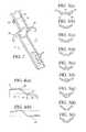
- FIG. 2is a perspective view of one end of a stay member having medial and lateral struts and a hinge away from the popliteal region of the knee joint.
- FIG. 3( a )is a cross-sectional view of the stay member taken at line 3 - 3 .
- FIGS. 3( b )- 3 ( i )are cross-sectional views of various alternative embodiment stay members.
- FIGS. 4( a ) and 4 ( b )are side elevational views of two stay members.
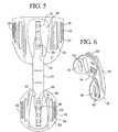
- FIG. 5is a rear elevational view of the stay member and cuff assembly without the liner.
- FIG. 6is a perspective view of one cuff detached from the stay member.
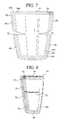
- FIG. 7is a front elevational view of a liner with the panels open.
- FIG. 8is a front elevational view of the line of FIG. 7 with the panels closed and secured by hook and loop fasteners.
- FIG. 9is a side elevational view of the line of FIG. 7 with the panels closed and secured by hook and loop fasteners.
- FIG. 10is a perspective view of an alternative embodiment knee immobilizer
- FIG. 11is a side elevational view of an alternative embodiment knee immobilizer attached to a leg of a patient.
- FIG. 12is a side elevational view of an alternative embodiment knee immobilizer with medial and lateral stay members.
- the present inventionis directed to an orthopedic brace for support of an injured limb.
- the present inventionis directed to a knee immobilizer.
- the knee immobilizer or brace 10is preferably constructed of a rigid support structure 12 acting as a spine and incorporates an optional foam compressive liner 14 and a strapping system consisting of four straps 16 , 18 , 20 , 22 .
- the knee immobilizer or brace 10is shown in normal use. It is attached to the posterior portion of a patient's leg 24 .
- the stay member 12at the top and bottom ends of the stay member 12 are the femoral and tibial cuffs 28 , 30 , respectively.
- the cuffs 28 , 30slide along the femoral and tibial portions 34 , 36 of the stay member 12 for quick adjustment of its overall length.
- An optional popliteal pad 32is attached to the stay member 12 to further provide support and protect the very sensitive popliteus area of the knee.
- the popliteal pad 32is secured to the stay member 12 at the slightly bent popliteal region 38 in between the femoral portion 34 and the tibial portion 36 , as best seen in FIG. 4( a ).
- the rigid stay member 12resists bending and gives overall stability to the assembly, while the cuffs 28 , 30 support and cradle the muscle bellies of the leg 24 .
- the liner 14 with the straps 16 , 28 , 20 , 22comfortably and securely hold the entire assembly to the leg 24 .
- the componentswork together to immobilize the knee joint and to further prevent unintended rotation of the upper and/or lower portion of the limb that might further injure the knee. Since the popliteal region 38 has no articulation or hinge, the strength and stability in that region are superior to that of a conventional design, and there is virtually no possibility of the knee joint moving if the patient or user is ambulatory.
- the rigid support structureis specifically a single-piece, rigid stay member 12 made from a unitary, uninterrupted-length bar of metal or high strength material.
- the stay member 12has a series of oval holes 26 spaced apart in a specified increments preferably located at both ends of the stay member 12 .
- the holes 26allow the positions of the cuffs 28 , 30 to be adjusted and set relative to the stay member 12 . This adjustment extends or shortens the overall length of the brace 10 to quickly and easily tailor fitment of the knee immobilizer to the unique anatomies of patients of different sex, height, age, physique, weight, etc.
- the stay member 12is shown in a side elevational view in FIG. 4( a ).
- the theoretical femoral portion 34 , tibial portion 36 and popliteal region 38are identified.
- a first curvature 35is defined whereat the femoral portion 34 merges with the popliteal region 38
- a second curvature 37is defined whereat the tibial portion 36 merges with the popliteal region 38 .
- the two horizontal dashed linesare parallel and meant to contrast the preferred profile contour of the stay member 12 , intended to closely follow the posterior contours of a human leg.
- the stay member 12begins as an extruded bar of aluminum having a straight profile, and is carefully fashioned with compound curves as shown in FIG. 4( a ),
- FIG. 4( b )shows an alternative embodiment stay member 40 with a steeper bend in the popliteal region and less angular peaks and valleys.
- FIG. 3( a )is a cross-sectional view of the stay member 12 taken along line 3 - 3 in FIG. 2 .
- the stay member 12has a bowed shape from edge to edge, and includes optional reinforced areas 42 underneath and reinforcement beads 44 .
- This cross-sectional shapepreferably runs uniformly from one end of the stay member 12 to the other. From empirical studies, the preferred embodiment stay member 12 shown in FIG. 3( a ) has a cross-sectional shape that has been engineered to provide the ideal strength-to-weight-to-size ration. It is preferable to minimize the depth of such a stay member in older to limit its effect and discomfort to the patient.
- FIGS. 3( b )- 3 ( i )illustrate the cross-sectional shapes of alternative embodiment stay members, some having a channel, reinforcement beads, etc. placed at different locations for best strength to weight ratio and optimum bending area moment of inertia.
- the stay member 12may be a solid material or may have a hollow core at least for a lengthwise section thereof as shown in the FIG. 3( g ) embodiments.
- the stay member 12is extruded from aluminum, but other high strength metals, laminated polymer composites, woven graphite, or fiber reinforced plastics or the like are contemplated.
- the polymers and metalscan be integrated or laminated for different strength, weight, cost, durability, and other engineering considerations.
- the stay membermay further take the form of bundled rods or multilayer bars or any combination thereof.
- the rods or barsmay be co-extruded with a polymer cladding in various alternative embodiments.
- the stay membershould at least meet a bending load of about 25 ft-lbs. or more for knee immobilizers to be used by adults.
- the length, width, thickness, and cross-sectional area moment of inertia of the stay membershould be considered to at least support such load bearing requirements.
- its lengthshould be sufficiently long so that the femoral portion 34 and the tibial portion 36 extend well past the popliteus for comfortable load bearing of the body weight of the patient or user, and to provide sufficient slide adjustment motion for the cuffs 28 , 30 .
- the brace 10spans from about 18 to 24 inches in overall length.
- lateral and medial struts 46 , 48have been added to die support. These two struts 46 , 48 are located on one or both sides of the knee, providing additional medial/lateral support and protection to the knee.
- the lateral and medial struts 46 , 48may be welded, bonded, Velcroed, fastened, or likewise mechanically attached to the stay member 12 or the liner 14 .
- Each strut 46 , 48optionally has a slight forward curvature to at least partially circumscribe the knee. The forward curvature gives some protection from accidental external impact and further stabilizes the injured knee.
- the lateral and medial struts 46 , 48may be simple cantilevered bars as shown in FIG. 2 , or may have a more integrated, complex form similar to the arches 78 shown in FIG. 10 except that the side hinges 82 are omitted.
- an optional articulation or hinge 50located away from the knee along the posterior of the leg.
- the hinge 50allows the stay member 12 to break into two discrete sections along separation line 52 and linked only at the hinge 50 . Once opened to a desired angle for the two sections, the hinge 50 can be locked down using a threaded nut or other means known in the art thus freezing the angle of the bend. The hinge 50 therefore gives greater adjustability to the stay member 12 for
- the stay membershould at least meet a bending load of about 25 ft-lbs. or more for knee immobilizers to be used by adults.
- the length, width, thickness, and cross-sectional area moment of inertia of the stay membershould be considered to at least support such load beating requirements.
- its lengthshould be sufficiently long so that the femoral portion 34 and the tibial portion 36 extend well past the popliteus for comfortable load bearing of the body weight of the patient or user, and to provide sufficient slide adjustment motion for the cuffs 28 , 30 .
- the brace 10spans from about 18 to 24 inches in overall length.
- lateral and medial struts 46 , 48have been added to the support. These two struts 46 , 48 are located on one or both sides of the knee, providing additional medial/lateral support and protection to the knee.
- the lateral and medial struts 46 , 48may be welded, bonded, Velcroed, fastened, or likewise mechanically attached to the stay member 12 or the liner 14 .
- Each strut 46 , 48optionally has a slight forward curvature to at least partially circumscribe the knee. The forward curvature gives some protection from accidental external impact and further stabilizes the injured knee.
- the lateral and medial struts 46 , 48may be simple cantilevered bars as shown in FIG. 2 , or may have a more integrated, complex form similar to the arches 78 shown in FIG. 10 except that the side hinges 82 are omitted.
- the hinge 50allows the stay member 12 to break into two discrete sections along separation line 52 and linked only at the hinge 50 . Once opened to a desired angle for the two sections, the hinge 50 can be locked down using a threaded nut or other means known in the art thus freezing the angle of the bend.
- the hinge 50therefore gives greater adjustability to the stay member 12 for improved fitment to the hamstring area (or calf area if the hinge is located there) of the patient's leg.
- Four holes 26 aare cut, drilled, or otherwise formed into the stay member 12 for setting the location of the tibial cuff 30 , mentioned earlier.
- the number, size, shape, and location of the holescan be modified from that shown to suit various design and engineering objectives.
- the stay membermay have score marks, notches, grooves, or the like so that its length can be more easily shortened by breaking off a section at the score mark rather than sliding the cuff along the length of stay.
- FIG. 5shows a rear view of the knee immobilizer with the liner 14 removed. Attached to the ends of the stay member 12 are the slightly larger femoral cuff 28 and the slightly smaller tibial cuff 30 .
- FIG. 6shows a single cuff 30 in a perspective view.
- These cuffs 28 , 30in a preferred embodiment are made of a semi-rigid plastic and are designed with strategically placed windows 54 to allow them to flex and shape around the anatomy of the leg.
- the cuffs 28 , 30have a generally curved or arcuate shape to at least partially circumscribe the leg. The curvature may be molded into the material, or the cuff may be formed flat and the curvature created by pulling on securing straps.
- each cuff 28 , 30has opposed arms 62 with an optional curl.
- the arms 62may have a thinner wall thickness than at the common base of the curve. All together, the thinner wall at the aims 62 and the windows 54 where material has been removed provide flexibility and diametrical adjustability of the cuff 28 , 30 for ideal user comfort and customized fitment to his or her leg.
- the bulkier base area of the cuff 28 , 30ensures stability and positive engagement when the cuff 28 , 30 is assembled to the adjusters 56 , 58 and stay member 12 .
- the cuff 30may have a patch of hook fastener material 64 for attachment of to the liner 14 .
- the wall thickness change in the arms 62may be gradual as shown, where the outer ends are the thinnest, or the change may be stepped.
- the size, location, and number of windows 54may be altered from that shown.
- the preferred shape for the windows 54is au elongated oval as shown, with the outermost windows 54 in the arms 62 being used for lacing one or more straps 16 , 22 therethrough, as shown in FIG. 1 .
- the cuffs 28 , 30are attached to the stay member 12 via a femoral adjuster 56 and a tibial adjuster 58 .
- the adjusters 56 , 58are attached to each respective cuff 28 , 30 by three rivets.
- Other means of attachmentare contemplated, such as by bonding the parts together, snap fitting, welding, or forming the cuff and adjuster in a single integral piece.
- the discrete adjuster and cuffare joined together by a hinge or pivot 39 as seen in FIG. 9 .
- the cuffhas a slight rocking action to more readily adapt to the user's unique leg shape.
- die knee immobilizermay have only one cuff, or more than two cuffs depending on the treatment necessary to the injured knee, the unique anatomy and physical needs of the patient, etc.
- the stay member 12easily slides inside the slots 60 created in each adjuster 56 , 58 , wherein the slots 60 are of the same shape as the outer surface of the stay member 12 .
- the adjusters 56 , 58enable each respective cuff 28 , 30 to freely slide linearly along the ends of the stay member 12 .
- a button assembly 66is used, which includes a button and spring.
- the button assembly 66is encapsulated between the cuff 28 , 30 and adjuster 56 , 58 during the riveting operation, wherein the button is biased by the spring into one of the holes 26 in the stay member 12 when the stay member 12 is located in the adjuster 56 , 58 .
- the length of the braceis adjusted by pressing the button down so the cuff assembly can be slid farther up or down the stay member 12 .
- the springforces the button up into that oval hole, thereby positively locking the location of the cuff 28 , 30 on the stay member 12 . This process is repeated until the desired size is achieved.
- each cuffcan be adjusted with one hand.
- the adjustmentis simple enough so that it can be performed by a patient or user with no training.
- the preferred embodimentcan be modified to rearrange the relative locations of the button, spring, and holes.
- the holesmay be located along the edge of the stay member with a biased pin extending sideways through the adjuster into the selected hole thus locking the two together.
- a positive mechanical engagementis achieved between the stay member and the cuff via the adjuster.
- the adjuster structurecan be omitted and a simple slot can be formed integrally into the cuff.
- a mechanical rack and pinion systemcan be used replacing the button assembly and holes, wherein the edges of the stay member have teeth that engage the complementary gear teeth of a rotating pinion, whose rotation can be locked down by a thumb screw to immobilize the overall relative sliding action.
- the pinioncan be replaced by a movable finger attached to the cuff that is spring biased into the teeth at the edge of the stay member. Rocking the finger over a pivot point or similarly withdrawing the finger away from the teeth enables the sliding action between the stay member and cuff.
- a frictional lockcan be used in the form of a pivoted lever that is rotated and wedged into contact with the stay member and the gripping contact surfaces are optionally covered with a high friction rubber or like grippy material.
- a deadbolt systemcan be implemented similar to its operation in a door, wherein the deadbolt slides under spring bias into a receiving hole in the stay member thus positively locking the two together.
- a stop or surface bumpcan be used in place of a hole.
- Yet another alternative embodimentcontemplates the stay member sliding inside the slot as shown in FIG. 1 , but the button assembly is replaced with a threaded thumb screw whose shaft extends through one of the holes or a longitudinal slot in the stay member.
- the tip of the advancing thumb screwcan be threaded into a corresponding hole, groove, or stop in the cuff or adjust. If the holes are replaced with a slot in this embodiment, the stop settings are not limited to four or however many holes are present but would be technically infinitely adjustable.
- the tip of the threaded shaftmay have a rubber cap to improve grip or wedging action, and to minimize damage to the stay member if the user overly torques the thumb screw. All such similar mechanical locking mechanisms are contemplated.
- the adjustercan be welded, bonded, or permanently secured or affixed to the stay member at one end thereof eliminating the slide adjustment while the opposite end of the stay member has a cuff that remains slide adjustable.
- the tibial cuffcan be permanently affixed to the stay member and the femoral cuff would slide along the stay for length adjustments and patient comfort.
- a pivot 39 as in FIG. 9is used between the adjuster and the cuff, there is some rocking action and “play” for the cuff relative to the stay member. Accordingly, a cuff may then be affixed to the stay member without any slide adjustment for rocking action only, or the pivot may add a rocking action in addition to the linear adjustment of the cuff.
- FIG. 7shows a preferred embodiment foam compressive liner (i.e., softgood) 14 with four panels 68 .
- the foam liner 14is made of a non-rigid porous material with UBL (unbroken loop) material laminated to both sides.
- the UBLcan be the same color or different colors to offer color options for the end user.
- hook fastenere.g., Velcro hooks
- tabs 70can be easily removed, relocated, and reapplied after optional trimming of the foam liner 14 for sizing.
- the tabs 70hold the foam liner 14 closed to free up the hands of the end user for securing the straps 16 , 18 , 20 , 22 .
- the diameter of the liner 14 at the topis greater than at the bottom to accommodate the greater diameter of the limb above the knee than below the knee.
- a slit or cut line 72is provided to relieve the pressure over the patella. Additional slits 73 may be provided as guides for further cutting of this slit when the liner is cut down in width for thinner mid/or smaller legs.
- the patellamay protrude through the slit if it is left open, or the patella may be covered by liner material.
- the linermay include size indicia or markings 100 to assist medical practitioners or the user in altering the liner to fit more properly or comfortably. These markings 100 may be perforations cut into the pattern during the die cut stage, or may be printed thereon to give visual guides to the medical practitioners during the trimming and sizing of the softgood liner.
- An ethylene foam linermay be added to the cuff for added padding and comfort.
- a patellar cut 72seen in FIGS. 7 and 8 , may be left open or covered in an elastic material that is sewn into the liner.
- the popliteal pad 32may be formed into the layers of or sewn into the liner 14 to minimize shifting of the pad 32 in use.
- the liner 14is preferably joined to the stay member 12 and/or one or more cuffs 28 , 30 via hook fasteners or Velcro patches.
- the liner 14can be a single sheet with pre-cut and pre-shaped panels 68 as depicted in FIG. 7 to nestle against the stay member 12 and one or both cuffs 28 , 30 .
- each cuffmay have its own discrete sheet of liner material.
- the linermay be bonded or sewn into the cuff, or be molded into the cuff. In short, the resilience, thickness, number of layers, overall shape, size, panel number and shape, and location of the liner or liners relative to the stay member and cuff can all be customized based on user requirements.
- the knee immobilizer 10is secured to the leg 24 via a strapping system consisting preferably of four straps, namely, two cuff straps 16 , 22 and two stay member straps 18 , 20 .
- Two of the straps 16 , 22are permanently attached to the cuffs 28 , 30 , one on each.
- the remaining two stay straps 18 , 20are adjustably attached to the rigid stay member 12 . That is, each stay strap 18 , 20 has an optional loop 74 through which the stay member 12 passes so that the straps can slide and adjust up and down the stay member 12 .
- stay straps 18 , 20can be temporarily or permanently affixed to the stay member 12 if desired by use of hook and loop fasteners, making a knot in the strap, adhesive bonding or welding, or a screw fastener or the like mechanical attachment.
- the cuff straps 16 , 22are preferably fastened using a hook and loop arrangement and D-rings 76 . It is possible to omit the hook and loop fasteners and simply tie a loot at the D-ring, or more preferably, replace the D-ring with a buckle or a clamp.
- the bucklesmay employ a side, top, and/or twist release.
- the liner 14is removably attached to the support structure (namely, the stay member 12 and cuffs 28 , 30 ) via strips of Velcro located on the cuffs 28 , 30 and the stay straps 18 , 20 , and can have a hook barrier (not shown) in place during shipping to prevent contact of these hook strips until the knee immobilizer is properly applied to the patient and adjusted.
- this additional Velcro hook barrieris removed from between the back stay member 12 and the foam liner 14 to allow the Velcro hook on the cuffs 28 , 30 and stay straps to grab onto the foam liner and further secure the knee immobilizer.
- FIG. 10is a perspective view of another alternative embodiment stay member 80 .
- the stay member 80includes the same adjustment means for tibial and femoral cuffs 28 , 30 as described above to accommodate various length legs on a brace having range of motion hinges 82 on both sides of the patient's knee.
- These side mounted hinges 82can be of the designs shown in, for example, U.S. Pat. No. 5,554,104 (Grim); U.S. Pat. No. D496,464 (Iglesias, et al.); and co-pending U.S. patent application Ser. No. 10/675,324, filed Sep. 29, 2003, titled “Adjustable Ergonomic Knee Brace,” by D.
- each hinge 82is located atop an arch 78 extending from the stay member 80 , wherein each arch 78 stretches toward the patella on either side of the knee to better restrain lateral and medial movement.
- the bracemay include a liner, or be made and worn without a liner with minimal padding on the cuffs and straps. Such a brace, described below, would tailor fit various length legs and would provide a post operative knee brace that would again resist pistoning due to the added fitment of the cuffs as described above.
- FIG. 11is a side elevational view of yet another alternative embodiment knee immobilizer 86 for use in warm or humid climates.
- the lineris altogether omitted and/or only a thin layer of liner material 98 is used to pad and cushion the cuffs 90 , 92 only. More preferably, the cushioning liner material 98 substantially covers only the areas of the cuffs 90 , 92 that touch the patient's leg and does not extend beyond that limited area.
- the cushioning liner material 98is further selected to be thinner with less padding as compared to the foam compressive liner 14 shown in FIG. 1 , for example.
- the foam compressive liner 14 in the exemplary embodimentis chosen for its ability to wrap around and stabilize the leg while applying a small amount of compressive pressure to the leg.
- the compressive linerhas a durometer of about 20-35 (using a 302SL sponge rubber gauge). It is known that the knee, ankle, or injured joint when immobilized has a tendency to swell. To minimize this swelling, it is further known in the art that applying the compressive pressure to the leg is beneficial, and hence the use of the compressive liner 14 .
- the cushioning liner 98is preferably not made from the softgood liner or UBL material. Rather, the cushioning liner 98 uses a foam or like material of sufficiently high durometer (ergs, durometer of 45-60 using a 302SL sponge rubber gauge) to keep the skin of the wearer from bottoming out in the padding and impacting the cuff.
- the cuff cushioning liner 98is made from a closed cell polyethylene foam, or spacer fabrics and the like. It may have a thickness of about 1 ⁇ 8 to 1 ⁇ 4 inch and anything therebetween when mounted to the cuff, while the compressive liner is typically thicker. Further, the closed cell cushioning liner 98 may have a laminate and/or coating thereon to prevent direct contact between foam and skin to reduce sweating.
- the “cool” knee immobilizer 86again includes components such as a rigid stay member 88 , one or more length adjustment cuffs 90 , 92 , and securing straps 94 , 96 .
- the straps 94 , 96would either be manufactured with a material that does not irritate the skin, or would have some form of padding, coating, or a cushioning liner applied to the skin-facing side.
- the femoral strap 96have a greater width for a more secure connection to the leg since the compressive liner is omitted.
- the femoral strap 96may apply slight compressive pressure on the leg in place of the omitted compressive liner.
- the wider femoral strap 96may have a width of about 3-4 inches wide instead of about 2 inches for the other straps 94 .
- any or all of the other straps 94 , 96may have greater widths for the same purposes.
- the leg 24 of the patientis mostly open to the ambient air and benefits from the air cooling effect accordingly.
- the knee immobilizer 86is less bulky, has a lower profile or silhouette, and can more easily fit underneath a patient's pants, rather than over his or her clothing as with most of the conventional products on the market must be worn.
- the knee immobilizer 86 without a compressive linerallows for a closer, more conforming fit of the cuffs 90 , 92 to the muscle belly of patient's leg, the issue of the cuffs unintended pistoning on the leg is virtually eliminated.
- FIG. 12is a side elevational view of the knee immobilizer 10 from FIG. 9 modified with medial and lateral stay members 84 .
- These optional medial and lateral stay members 84are held in place by straps 16 , 18 , 20 , 22 and overlies the liner 14 . More preferably, the medial and lateral stay members 84 are Velcroed, strapped, or otherwise mechanically attached to the liner 14 .
- the primary stay member 12 at the posterior of the leg 24is still used as are the sliding cuffs 28 , 30 .
- the medial and lateral stay members 84are located on either side of the injured knee for added medial and lateral support and protection of the knee.
- the medial and lateral stay members 84may be made from aluminum bars, rigid plastic strips, or the like, and have a straight length or include a slight bend to follow the contours of the leg.
Landscapes
- Health & Medical Sciences (AREA)
- Nursing (AREA)
- Orthopedic Medicine & Surgery (AREA)
- Engineering & Computer Science (AREA)
- Biomedical Technology (AREA)
- Heart & Thoracic Surgery (AREA)
- Vascular Medicine (AREA)
- Life Sciences & Earth Sciences (AREA)
- Animal Behavior & Ethology (AREA)
- General Health & Medical Sciences (AREA)
- Public Health (AREA)
- Veterinary Medicine (AREA)
- Orthopedics, Nursing, And Contraception (AREA)
Abstract
Description
Claims (9)
Priority Applications (1)
| Application Number | Priority Date | Filing Date | Title |
|---|---|---|---|
| US12/408,017US7892195B2 (en) | 2005-01-12 | 2009-03-20 | Knee immobilizer |
Applications Claiming Priority (2)
| Application Number | Priority Date | Filing Date | Title |
|---|---|---|---|
| US11/035,133US7513881B1 (en) | 2005-01-12 | 2005-01-12 | Knee immobilizer |
| US12/408,017US7892195B2 (en) | 2005-01-12 | 2009-03-20 | Knee immobilizer |
Related Parent Applications (1)
| Application Number | Title | Priority Date | Filing Date |
|---|---|---|---|
| US11/035,133ContinuationUS7513881B1 (en) | 2005-01-12 | 2005-01-12 | Knee immobilizer |
Publications (2)
| Publication Number | Publication Date |
|---|---|
| US20090182253A1 US20090182253A1 (en) | 2009-07-16 |
| US7892195B2true US7892195B2 (en) | 2011-02-22 |
Family
ID=40512692
Family Applications (2)
| Application Number | Title | Priority Date | Filing Date |
|---|---|---|---|
| US11/035,133Active2026-04-30US7513881B1 (en) | 2005-01-12 | 2005-01-12 | Knee immobilizer |
| US12/408,017Expired - Fee RelatedUS7892195B2 (en) | 2005-01-12 | 2009-03-20 | Knee immobilizer |
Family Applications Before (1)
| Application Number | Title | Priority Date | Filing Date |
|---|---|---|---|
| US11/035,133Active2026-04-30US7513881B1 (en) | 2005-01-12 | 2005-01-12 | Knee immobilizer |
Country Status (1)
| Country | Link |
|---|---|
| US (2) | US7513881B1 (en) |
Cited By (31)
| Publication number | Priority date | Publication date | Assignee | Title |
|---|---|---|---|---|
| US20040064195A1 (en)* | 2002-07-15 | 2004-04-01 | Hugh Herr | Variable-mechanical-impedance artificial legs |
| US20100113980A1 (en)* | 2008-09-04 | 2010-05-06 | Iwalk, Inc. | Hybrid Terrain-Adaptive Lower-Extremity Systems |
| US20100114329A1 (en)* | 2005-03-31 | 2010-05-06 | Iwalk, Inc. | Hybrid terrain-adaptive lower-extremity systems |
| US20100241242A1 (en)* | 2005-03-31 | 2010-09-23 | Massachusetts Institute Of Technology | Artificial Joints Using Agonist-Antagonist Actuators |
| US20100324699A1 (en)* | 2005-03-31 | 2010-12-23 | Massachusetts Institute Of Technology | Model-Based Neuromechanical Controller for a Robotic Leg |
| US20110040216A1 (en)* | 2005-03-31 | 2011-02-17 | Massachusetts Institute Of Technology | Exoskeletons for running and walking |
| US20110082566A1 (en)* | 2008-09-04 | 2011-04-07 | Herr Hugh M | Implementing a stand-up sequence using a lower-extremity prosthesis or orthosis |
| US8287477B1 (en) | 2003-09-25 | 2012-10-16 | Massachusetts Institute Of Technology | Active ankle foot orthosis |
| US8500823B2 (en) | 2005-03-31 | 2013-08-06 | Massachusetts Institute Of Technology | Powered artificial knee with agonist-antagonist actuation |
| US8512415B2 (en) | 2005-03-31 | 2013-08-20 | Massachusetts Institute Of Technology | Powered ankle-foot prothesis |
| US8636681B1 (en) | 2012-10-15 | 2014-01-28 | Mohamad Saad Farhan Mutairan Al-Azmi | Splint for the entire leg |
| US20140114222A1 (en)* | 2012-10-23 | 2014-04-24 | Monica Ann Volker | Leg brace |
| US8734528B2 (en) | 2005-03-31 | 2014-05-27 | Massachusetts Institute Of Technology | Artificial ankle-foot system with spring, variable-damping, and series-elastic actuator components |
| US20150038890A1 (en)* | 2013-07-31 | 2015-02-05 | Clinton James Montgomery | Knee Immobilizer Support Cuff |
| US9032635B2 (en) | 2011-12-15 | 2015-05-19 | Massachusetts Institute Of Technology | Physiological measurement device or wearable device interface simulator and method of use |
| US9060883B2 (en) | 2011-03-11 | 2015-06-23 | Iwalk, Inc. | Biomimetic joint actuators |
| US9221177B2 (en) | 2012-04-18 | 2015-12-29 | Massachusetts Institute Of Technology | Neuromuscular model-based sensing and control paradigm for a robotic leg |
| US9333097B2 (en) | 2005-03-31 | 2016-05-10 | Massachusetts Institute Of Technology | Artificial human limbs and joints employing actuators, springs, and variable-damper elements |
| US20160166914A1 (en)* | 2012-10-17 | 2016-06-16 | Lekisport Ag | Dynamic shin guard |
| US9687377B2 (en) | 2011-01-21 | 2017-06-27 | Bionx Medical Technologies, Inc. | Terrain adaptive powered joint orthosis |
| US9693883B2 (en) | 2010-04-05 | 2017-07-04 | Bionx Medical Technologies, Inc. | Controlling power in a prosthesis or orthosis based on predicted walking speed or surrogate for same |
| US9737419B2 (en) | 2011-11-02 | 2017-08-22 | Bionx Medical Technologies, Inc. | Biomimetic transfemoral prosthesis |
| US9839552B2 (en) | 2011-01-10 | 2017-12-12 | Bionx Medical Technologies, Inc. | Powered joint orthosis |
| US20180304136A1 (en)* | 2015-10-09 | 2018-10-25 | Sport 40 40 LLC | Swing Training Device |
| US10307272B2 (en) | 2005-03-31 | 2019-06-04 | Massachusetts Institute Of Technology | Method for using a model-based controller for a robotic leg |
| US10531965B2 (en) | 2012-06-12 | 2020-01-14 | Bionx Medical Technologies, Inc. | Prosthetic, orthotic or exoskeleton device |
| US10537449B2 (en) | 2011-01-12 | 2020-01-21 | Bionx Medical Technologies, Inc. | Controlling powered human augmentation devices |
| US10842653B2 (en) | 2007-09-19 | 2020-11-24 | Ability Dynamics, Llc | Vacuum system for a prosthetic foot |
| US11278433B2 (en) | 2005-03-31 | 2022-03-22 | Massachusetts Institute Of Technology | Powered ankle-foot prosthesis |
| US11918500B1 (en) | 2020-03-31 | 2024-03-05 | Preferred Prescription, Inc. | Hinged knee brace with double upper strap arrangement |
| US12121463B1 (en) | 2020-02-13 | 2024-10-22 | Preferred Prescription, Inc. | Knee/elbow brace |
Families Citing this family (41)
| Publication number | Priority date | Publication date | Assignee | Title |
|---|---|---|---|---|
| US8663144B2 (en) | 2004-03-22 | 2014-03-04 | Farrow Medical Innovations Holdings Llc | Modular compression device and method of assembly |
| US7942838B2 (en) | 2004-03-22 | 2011-05-17 | Farrow Medical Innovations, Inc. | Compression garment |
| WO2008044207A2 (en)* | 2006-10-13 | 2008-04-17 | Koninklijke Philips Electronics N.V. | Switchable joint constraint system |
| CN102026595B (en)* | 2008-05-14 | 2013-11-20 | 奥苏尔公司 | Leg support |
| US20100022927A1 (en)* | 2008-07-23 | 2010-01-28 | Linares Medical Devices, Llc | Body limb cast with key adjustable outer cage and inner foam support members for maintaining breathe-ability |
| US20100056973A1 (en)* | 2008-08-28 | 2010-03-04 | Farrow Medical Innovations, Inc. | Therapeutic Compression Garments |
| US8376977B2 (en) | 2008-08-28 | 2013-02-19 | Wade P. Farrow | Trim-to-fit therapeutic compression garment system and method |
| US8257290B2 (en)* | 2008-09-05 | 2012-09-04 | Linares Medical Devices, Llc | Temporary splint assembly with semi-rigid wrap around supports in combination with intermediately positioned joint cast |
| CN102333502B (en) | 2009-02-26 | 2014-06-25 | 欧苏尔公司 | Orthopedic devices used to treat the back |
| EP2440167B1 (en)* | 2009-06-08 | 2016-05-25 | Farrow Innovations LLC | Customizable therapeutic compression garment and method |
| US8657769B2 (en) | 2009-11-04 | 2014-02-25 | Ossur Hf | Thoracic lumbar sacral orthosis |
| US9180038B2 (en) | 2010-08-05 | 2015-11-10 | Ossur Hf | Walker having height adjustment and method for doing the same |
| WO2012177700A2 (en)* | 2011-06-20 | 2012-12-27 | Ossur Hf | Orthopedic device, use of orthopedic device and method for producing the same |
| US10092435B2 (en) | 2011-10-28 | 2018-10-09 | Bracemasters International, Llc | Ankle brace and method of making the same |
| US9572705B2 (en) | 2012-01-13 | 2017-02-21 | Ossur Hf | Spinal orthosis |
| WO2013106666A1 (en) | 2012-01-13 | 2013-07-18 | Ossur Hf | Spinal orthosis and method for using the same |
| US9925082B2 (en) | 2012-03-20 | 2018-03-27 | Ossur Hf | Orthopedic device |
| US10258831B1 (en)* | 2012-09-14 | 2019-04-16 | Catherine Grander Vance | Swim training devices |
| EP2897559B1 (en) | 2012-09-19 | 2019-03-06 | Ossur HF | Panel attachment and circumference adjustment systems for an orthopedic device |
| GB2509801B (en)* | 2013-01-15 | 2016-02-17 | Univ Loughborough | Splint |
| WO2014116895A1 (en) | 2013-01-24 | 2014-07-31 | Ossur Hf | Orthopedic device for treating complications of the hip |
| US9795500B2 (en) | 2013-01-24 | 2017-10-24 | Ossur Hf | Orthopedic device for treating complications of the hip |
| US9554935B2 (en) | 2013-01-24 | 2017-01-31 | Ossur Hf | Orthopedic device for treating complications of the hip |
| US10357391B2 (en) | 2013-01-24 | 2019-07-23 | Ossur Hf | Orthopedic device for treating complications of the hip |
| US9839547B2 (en)* | 2013-01-30 | 2017-12-12 | Bracemasters International, Llc | Ankle foot orthosis (AFO) and method of making the same |
| US10092436B2 (en)* | 2013-03-15 | 2018-10-09 | Bracemasters International, Llc | Ankle foot orthosis (AFO) and method of making the same |
| USD779077S1 (en) | 2014-09-22 | 2017-02-14 | Bracemasters International, Llc | Ankle brace |
| CN104490504B (en)* | 2014-12-30 | 2016-08-17 | 桂林电子科技大学 | A kind of special angle joint support joint protective device |
| US10561520B2 (en) | 2015-02-27 | 2020-02-18 | Ossur Iceland Ehf | Spinal orthosis, kit and method for using the same |
| WO2016138215A1 (en) | 2015-02-27 | 2016-09-01 | Ossur Iceland Ehf | Spinal orthosis, kit and method for using the same |
| US20170224519A1 (en)* | 2016-02-08 | 2017-08-10 | Townsend Industries, Inc. d/b/a Townsend Design | Knee brace with a mechanism enabling changing of cuff shells |
| US11662058B2 (en)* | 2016-02-15 | 2023-05-30 | Honda Motor Co., Ltd. | Orthotic device for use with user-operated tool |
| US11389315B2 (en) | 2016-02-15 | 2022-07-19 | Honda Motor Co., Ltd. | Orthotic device responsive to detected forces at user-operated tool |
| DE102016104877B4 (en)* | 2016-03-16 | 2024-09-05 | Ottobock Se & Co. Kgaa | Orthopaedic technical facility |
| WO2017176680A1 (en) | 2016-04-04 | 2017-10-12 | Ossur Iceland Ehf | Orthopedic device |
| SE1651557A1 (en)* | 2016-11-28 | 2018-05-29 | Danderyds Sjukhus Ab | Medical support |
| EP3678613B1 (en) | 2017-09-07 | 2023-08-09 | Össur Iceland EHF | Thoracic lumbar sacral orthosis attachment |
| US11000439B2 (en) | 2017-09-28 | 2021-05-11 | Ossur Iceland Ehf | Body interface |
| US11304830B2 (en)* | 2017-10-11 | 2022-04-19 | Robert Brown | Flexible multi use post operative prosthetic socket system |
| CN113194889B (en) | 2018-12-20 | 2024-02-13 | Djo有限责任公司 | Braces that limit range of motion and how to use them |
| US11660223B1 (en)* | 2022-01-25 | 2023-05-30 | King Abdulaziz University | Smart knee brace for post-surgery rehabilitation |
Citations (53)
| Publication number | Priority date | Publication date | Assignee | Title |
|---|---|---|---|---|
| US183376A (en) | 1876-10-17 | Improvement in apparatus for contracted joints | ||
| US552143A (en) | 1895-12-31 | Adjustable splint | ||
| US3304937A (en) | 1964-07-24 | 1967-02-21 | Jr George R Callender | Derotation brace for tibia deformities |
| US3526222A (en) | 1968-05-24 | 1970-09-01 | Robert E Dreibelbis | Pediatric restraining apparatus |
| US3831467A (en) | 1973-03-16 | 1974-08-27 | R Moore | Knee brace |
| US3933154A (en) | 1974-01-15 | 1976-01-20 | Cabansag Edwin M | Immobilizer device |
| US3935858A (en) | 1975-01-13 | 1976-02-03 | Orthopedic Equipment Company, Inc. | Knee immobilizer |
| US3958567A (en) | 1975-04-29 | 1976-05-25 | Callender Jr George R | Derotation brace for tibia deformities |
| US4041940A (en) | 1975-11-05 | 1977-08-16 | Frankel S Arthur | Contoured knee immobilizer |
| US4050455A (en) | 1976-07-26 | 1977-09-27 | The Raymond Lee Organization, Inc. | Foot and leg brace |
| US4090508A (en) | 1977-03-15 | 1978-05-23 | Medical Specialties, Incorporated | Orthopedic knee brace |
| US4111194A (en) | 1976-12-27 | 1978-09-05 | Rollin Webb Cox | Posterior knee immobilizing brace |
| US4198964A (en) | 1979-01-11 | 1980-04-22 | Zimmer Usa, Inc. | Acromioclavicular brace |
| US4388920A (en) | 1981-10-26 | 1983-06-21 | Professional Medical Products, Inc. | Variable position knee immobilizer |
| US4407276A (en) | 1981-01-22 | 1983-10-04 | Medical Designs, Inc. | Brace for articulated limbs |
| DE3520939A1 (en) | 1985-06-12 | 1986-12-18 | Sanitätshaus Heinz Pfau GmbH & Co KG, 1000 Berlin | Knee-guiding arrangement for correction of defective positions of the knee-joint |
| US4776326A (en) | 1985-07-09 | 1988-10-11 | Protectair Ltd. | Modular lower limb bracing system |
| US4796610A (en) | 1987-07-02 | 1989-01-10 | Donjoy, Inc. | Lateral impact knee guard and medial collateral ligament knee brace |
| US4844326A (en) | 1987-10-08 | 1989-07-04 | Mazda Motor Corporation | Method of and system for assembling vehicle bodies |
| US4848326A (en) | 1988-06-20 | 1989-07-18 | Robert Lonardo | Knee contracture correction device |
| US4981132A (en) | 1990-04-30 | 1991-01-01 | Andrew Chong | Orthosis for the treatment of tibial torsion in children |
| US4982732A (en) | 1990-02-06 | 1991-01-08 | Orthopedic Technology, Inc. | Orthopedic rehabilitation knee brace |
| US5007415A (en) | 1989-08-04 | 1991-04-16 | John E. Garber | Joint brace |
| US5088479A (en) | 1990-04-26 | 1992-02-18 | Detoro William W | Ankle and foot orthosis |
| US5116296A (en) | 1991-04-26 | 1992-05-26 | Medmetric Corporation | Isometric leg muscle ergometer |
| US5230700A (en) | 1989-04-28 | 1993-07-27 | Charles Humbert | Orthopedic apparatus for persons handicapped in one leg |
| US5230335A (en) | 1991-01-23 | 1993-07-27 | Aircast, Inc. | Thermal compress system |
| WO1993015251A1 (en) | 1992-02-03 | 1993-08-05 | Fiberweb North America, Inc. | Elastic nonwoven webs and method of making same |
| US5267949A (en) | 1992-03-25 | 1993-12-07 | Manuel De La Torre | Positioning device for a lower extremity |
| US5385534A (en) | 1993-07-09 | 1995-01-31 | Smith & Nephew Donjoy Inc. | Splint assembled from a flat stackable kit |
| US5387185A (en) | 1993-11-08 | 1995-02-07 | Aircast, Incorporated | Knee immobilizer splint |
| US5401235A (en) | 1992-06-03 | 1995-03-28 | Devens; Mark F. | Dynamic variable torque long bone torsion reducer |
| US5486157A (en) | 1994-02-03 | 1996-01-23 | Dibenedetto; Anthony | Dynamic multi-angular ankle and foot orthosis device |
| US5545127A (en) | 1995-04-24 | 1996-08-13 | Detoro; William | Laterally adjustable ankle and foot orthosis |
| US5554104A (en) | 1992-12-18 | 1996-09-10 | Royce Medical Company | Custom formable knee brace |
| US5571206A (en) | 1994-05-16 | 1996-11-05 | Restorative Care Of America Incorporated | Leg amputee orthosis |
| US5593383A (en) | 1995-03-20 | 1997-01-14 | Detoro; William | Securing apparatus for an ankle and foot orthosis |
| US5732411A (en) | 1996-04-04 | 1998-03-31 | Trace Athletic Corporation | Adjustable guard for the lower leg and shin |
| US5788658A (en) | 1997-01-31 | 1998-08-04 | Islava; Steven T. | Field adjustable extrication collar |
| US5823931A (en)* | 1996-02-21 | 1998-10-20 | Bodyworks Healthcare Limited | Knee brace |
| US5908398A (en) | 1998-01-27 | 1999-06-01 | Detoro; William W. | Ajustable ankle and foot orthosis brace |
| US6200286B1 (en) | 1998-06-11 | 2001-03-13 | M. Hashem Zamani | Preformed member having raised contact feature and wrist brace using same |
| US6302858B1 (en) | 2000-10-26 | 2001-10-16 | Anatomical Concepts, Inc. | Compound adjustable ankle foot orthosis brace |
| US6350246B1 (en) | 2000-02-23 | 2002-02-26 | Anatomical Concepts, Inc. | Ankle and foot therapeutic device |
| US6377178B1 (en) | 2000-06-20 | 2002-04-23 | William DeToro | Therapeutic ankle & foot apparatus having a contact sensor mechanism |
| US6383156B1 (en) | 1999-09-27 | 2002-05-07 | Dj Orthopedics, Llc | Orthopaedic brace having a range of motion hinge with an adjustable-length strut |
| US20020072695A1 (en) | 2000-12-12 | 2002-06-13 | Doty Del Ray | Orthopedic brace having length-adjustable supports |
| US6464659B1 (en) | 2001-06-18 | 2002-10-15 | Anatomical Concepts, Inc. | Pressure relief insert for therapeutic foot enclosures |
| US6592539B1 (en) | 1999-03-01 | 2003-07-15 | Ossur Hf | Orthotic or prosthetic sleeve formed of elasticized fabric sections having different elastic stiffness |
| US6719713B2 (en) | 2002-03-14 | 2004-04-13 | Breg, Inc. | Strap attachment assembly for an orthopedic brace |
| USD496464S1 (en) | 2003-09-29 | 2004-09-21 | Royce Medical Company | Adjustable knee brace pivot assembly |
| US7011641B1 (en) | 2003-10-29 | 2006-03-14 | Anatomical Concepts, Inc. | Knee brace immobilizer |
| US7682323B2 (en)* | 2008-07-21 | 2010-03-23 | Anatomical Concepts, Inc. | Coordinated cuff displacement in an orthotic device |
- 2005
- 2005-01-12USUS11/035,133patent/US7513881B1/enactiveActive
- 2009
- 2009-03-20USUS12/408,017patent/US7892195B2/ennot_activeExpired - Fee Related
Patent Citations (58)
| Publication number | Priority date | Publication date | Assignee | Title |
|---|---|---|---|---|
| US183376A (en) | 1876-10-17 | Improvement in apparatus for contracted joints | ||
| US552143A (en) | 1895-12-31 | Adjustable splint | ||
| US3304937A (en) | 1964-07-24 | 1967-02-21 | Jr George R Callender | Derotation brace for tibia deformities |
| US3526222A (en) | 1968-05-24 | 1970-09-01 | Robert E Dreibelbis | Pediatric restraining apparatus |
| US3831467A (en) | 1973-03-16 | 1974-08-27 | R Moore | Knee brace |
| US3933154A (en) | 1974-01-15 | 1976-01-20 | Cabansag Edwin M | Immobilizer device |
| US3935858A (en) | 1975-01-13 | 1976-02-03 | Orthopedic Equipment Company, Inc. | Knee immobilizer |
| US3958567A (en) | 1975-04-29 | 1976-05-25 | Callender Jr George R | Derotation brace for tibia deformities |
| US4041940A (en) | 1975-11-05 | 1977-08-16 | Frankel S Arthur | Contoured knee immobilizer |
| US4050455A (en) | 1976-07-26 | 1977-09-27 | The Raymond Lee Organization, Inc. | Foot and leg brace |
| US4111194A (en) | 1976-12-27 | 1978-09-05 | Rollin Webb Cox | Posterior knee immobilizing brace |
| US4090508A (en) | 1977-03-15 | 1978-05-23 | Medical Specialties, Incorporated | Orthopedic knee brace |
| US4198964A (en) | 1979-01-11 | 1980-04-22 | Zimmer Usa, Inc. | Acromioclavicular brace |
| US4407276A (en) | 1981-01-22 | 1983-10-04 | Medical Designs, Inc. | Brace for articulated limbs |
| US4388920A (en) | 1981-10-26 | 1983-06-21 | Professional Medical Products, Inc. | Variable position knee immobilizer |
| DE3520939A1 (en) | 1985-06-12 | 1986-12-18 | Sanitätshaus Heinz Pfau GmbH & Co KG, 1000 Berlin | Knee-guiding arrangement for correction of defective positions of the knee-joint |
| US4776326A (en) | 1985-07-09 | 1988-10-11 | Protectair Ltd. | Modular lower limb bracing system |
| US4796610A (en) | 1987-07-02 | 1989-01-10 | Donjoy, Inc. | Lateral impact knee guard and medial collateral ligament knee brace |
| US4844326A (en) | 1987-10-08 | 1989-07-04 | Mazda Motor Corporation | Method of and system for assembling vehicle bodies |
| US4848326A (en) | 1988-06-20 | 1989-07-18 | Robert Lonardo | Knee contracture correction device |
| US5230700A (en) | 1989-04-28 | 1993-07-27 | Charles Humbert | Orthopedic apparatus for persons handicapped in one leg |
| US5007415A (en) | 1989-08-04 | 1991-04-16 | John E. Garber | Joint brace |
| US4982732A (en) | 1990-02-06 | 1991-01-08 | Orthopedic Technology, Inc. | Orthopedic rehabilitation knee brace |
| US5088479A (en) | 1990-04-26 | 1992-02-18 | Detoro William W | Ankle and foot orthosis |
| US4981132A (en) | 1990-04-30 | 1991-01-01 | Andrew Chong | Orthosis for the treatment of tibial torsion in children |
| US5230335A (en) | 1991-01-23 | 1993-07-27 | Aircast, Inc. | Thermal compress system |
| US5116296A (en) | 1991-04-26 | 1992-05-26 | Medmetric Corporation | Isometric leg muscle ergometer |
| WO1993015251A1 (en) | 1992-02-03 | 1993-08-05 | Fiberweb North America, Inc. | Elastic nonwoven webs and method of making same |
| US5267949A (en) | 1992-03-25 | 1993-12-07 | Manuel De La Torre | Positioning device for a lower extremity |
| US5401235A (en) | 1992-06-03 | 1995-03-28 | Devens; Mark F. | Dynamic variable torque long bone torsion reducer |
| US5554104A (en) | 1992-12-18 | 1996-09-10 | Royce Medical Company | Custom formable knee brace |
| US5385534A (en) | 1993-07-09 | 1995-01-31 | Smith & Nephew Donjoy Inc. | Splint assembled from a flat stackable kit |
| US5387185A (en) | 1993-11-08 | 1995-02-07 | Aircast, Incorporated | Knee immobilizer splint |
| US5486157A (en) | 1994-02-03 | 1996-01-23 | Dibenedetto; Anthony | Dynamic multi-angular ankle and foot orthosis device |
| US5571206A (en) | 1994-05-16 | 1996-11-05 | Restorative Care Of America Incorporated | Leg amputee orthosis |
| US5593383A (en) | 1995-03-20 | 1997-01-14 | Detoro; William | Securing apparatus for an ankle and foot orthosis |
| US5545127A (en) | 1995-04-24 | 1996-08-13 | Detoro; William | Laterally adjustable ankle and foot orthosis |
| US5823931A (en)* | 1996-02-21 | 1998-10-20 | Bodyworks Healthcare Limited | Knee brace |
| US5732411A (en) | 1996-04-04 | 1998-03-31 | Trace Athletic Corporation | Adjustable guard for the lower leg and shin |
| US5788658A (en) | 1997-01-31 | 1998-08-04 | Islava; Steven T. | Field adjustable extrication collar |
| US5908398A (en) | 1998-01-27 | 1999-06-01 | Detoro; William W. | Ajustable ankle and foot orthosis brace |
| US5944679A (en) | 1998-01-27 | 1999-08-31 | Detoro; William W. | Adjustable ankle and foot orthosis brace |
| US6200286B1 (en) | 1998-06-11 | 2001-03-13 | M. Hashem Zamani | Preformed member having raised contact feature and wrist brace using same |
| US6592539B1 (en) | 1999-03-01 | 2003-07-15 | Ossur Hf | Orthotic or prosthetic sleeve formed of elasticized fabric sections having different elastic stiffness |
| US20020183672A1 (en) | 1999-09-27 | 2002-12-05 | Robert-Jan Enzerink | Orthopaedic brace having a range of motion hinge with an adjustable-length strut |
| US6383156B1 (en) | 1999-09-27 | 2002-05-07 | Dj Orthopedics, Llc | Orthopaedic brace having a range of motion hinge with an adjustable-length strut |
| US6350246B1 (en) | 2000-02-23 | 2002-02-26 | Anatomical Concepts, Inc. | Ankle and foot therapeutic device |
| US6377178B1 (en) | 2000-06-20 | 2002-04-23 | William DeToro | Therapeutic ankle & foot apparatus having a contact sensor mechanism |
| US6302858B1 (en) | 2000-10-26 | 2001-10-16 | Anatomical Concepts, Inc. | Compound adjustable ankle foot orthosis brace |
| US20020072695A1 (en) | 2000-12-12 | 2002-06-13 | Doty Del Ray | Orthopedic brace having length-adjustable supports |
| US6821261B2 (en) | 2000-12-12 | 2004-11-23 | Dj Orthopedics, Llc | Orthopedic brace having length-adjustable supports |
| US7128723B2 (en) | 2000-12-12 | 2006-10-31 | Dj Orthopedics, Llc | Orthopedic brace having length-adjustable supports |
| US6464659B1 (en) | 2001-06-18 | 2002-10-15 | Anatomical Concepts, Inc. | Pressure relief insert for therapeutic foot enclosures |
| US6719713B2 (en) | 2002-03-14 | 2004-04-13 | Breg, Inc. | Strap attachment assembly for an orthopedic brace |
| USD496464S1 (en) | 2003-09-29 | 2004-09-21 | Royce Medical Company | Adjustable knee brace pivot assembly |
| US7011641B1 (en) | 2003-10-29 | 2006-03-14 | Anatomical Concepts, Inc. | Knee brace immobilizer |
| US7122016B1 (en) | 2003-10-29 | 2006-10-17 | Anatomical Concepts, Inc. | Knee brace immobilizer |
| US7682323B2 (en)* | 2008-07-21 | 2010-03-23 | Anatomical Concepts, Inc. | Coordinated cuff displacement in an orthotic device |
Non-Patent Citations (2)
| Title |
|---|
| Celebrating The Introduction of the KMO Knee Management Orthosis, Anatomical Concepts, Inc., Product brochure. |
| U.S. Appl. No. 10/675,324, filed Sep. 29, 2003, Cormier et al. |
Cited By (67)
| Publication number | Priority date | Publication date | Assignee | Title |
|---|---|---|---|---|
| US20040064195A1 (en)* | 2002-07-15 | 2004-04-01 | Hugh Herr | Variable-mechanical-impedance artificial legs |
| US8551184B1 (en) | 2002-07-15 | 2013-10-08 | Iwalk, Inc. | Variable mechanical-impedance artificial legs |
| US10695256B2 (en) | 2003-09-25 | 2020-06-30 | Massachusetts Institute Of Technology | Motorized limb assistance device |
| US9668888B2 (en) | 2003-09-25 | 2017-06-06 | Massachusetts Institute Of Technology | Active ankle foot orthosis |
| US8808214B2 (en) | 2003-09-25 | 2014-08-19 | Massachusetts Institute Of Technology | Active ankle foot orthosis |
| US8551029B1 (en) | 2003-09-25 | 2013-10-08 | Massachusetts Institute Of Technology | Active ankle foot orthosis |
| US8376971B1 (en) | 2003-09-25 | 2013-02-19 | Massachusetts Institute Of Technology | Active ankle foot orthosis |
| US8287477B1 (en) | 2003-09-25 | 2012-10-16 | Massachusetts Institute Of Technology | Active ankle foot orthosis |
| US8512415B2 (en) | 2005-03-31 | 2013-08-20 | Massachusetts Institute Of Technology | Powered ankle-foot prothesis |
| US8734528B2 (en) | 2005-03-31 | 2014-05-27 | Massachusetts Institute Of Technology | Artificial ankle-foot system with spring, variable-damping, and series-elastic actuator components |
| US20100324699A1 (en)* | 2005-03-31 | 2010-12-23 | Massachusetts Institute Of Technology | Model-Based Neuromechanical Controller for a Robotic Leg |
| US20100241242A1 (en)* | 2005-03-31 | 2010-09-23 | Massachusetts Institute Of Technology | Artificial Joints Using Agonist-Antagonist Actuators |
| US10588759B2 (en) | 2005-03-31 | 2020-03-17 | Massachusetts Institute Of Technology | Artificial human limbs and joints employing actuators, springs and variable-damper elements |
| US8500823B2 (en) | 2005-03-31 | 2013-08-06 | Massachusetts Institute Of Technology | Powered artificial knee with agonist-antagonist actuation |
| US9339397B2 (en) | 2005-03-31 | 2016-05-17 | Massachusetts Institute Of Technology | Artificial ankle-foot system with spring, variable-damping, and series-elastic actuator components |
| US9333097B2 (en) | 2005-03-31 | 2016-05-10 | Massachusetts Institute Of Technology | Artificial human limbs and joints employing actuators, springs, and variable-damper elements |
| US11273060B2 (en) | 2005-03-31 | 2022-03-15 | Massachusetts Institute Of Technology | Artificial ankle-foot system with spring, variable-damping, and series-elastic actuator components |
| US10485681B2 (en) | 2005-03-31 | 2019-11-26 | Massachusetts Institute Of Technology | Exoskeletons for running and walking |
| US10342681B2 (en) | 2005-03-31 | 2019-07-09 | Massachusetts Institute Of Technology | Artificial ankle-foot system with spring, variable-damping, and series-elastic actuator components |
| US20110040216A1 (en)* | 2005-03-31 | 2011-02-17 | Massachusetts Institute Of Technology | Exoskeletons for running and walking |
| US11278433B2 (en) | 2005-03-31 | 2022-03-22 | Massachusetts Institute Of Technology | Powered ankle-foot prosthesis |
| US8864846B2 (en) | 2005-03-31 | 2014-10-21 | Massachusetts Institute Of Technology | Model-based neuromechanical controller for a robotic leg |
| US8870967B2 (en) | 2005-03-31 | 2014-10-28 | Massachusetts Institute Of Technology | Artificial joints using agonist-antagonist actuators |
| US10307272B2 (en) | 2005-03-31 | 2019-06-04 | Massachusetts Institute Of Technology | Method for using a model-based controller for a robotic leg |
| US10137011B2 (en) | 2005-03-31 | 2018-11-27 | Massachusetts Institute Of Technology | Powered ankle-foot prosthesis |
| US10080672B2 (en) | 2005-03-31 | 2018-09-25 | Bionx Medical Technologies, Inc. | Hybrid terrain-adaptive lower-extremity systems |
| US20100114329A1 (en)* | 2005-03-31 | 2010-05-06 | Iwalk, Inc. | Hybrid terrain-adaptive lower-extremity systems |
| US9149370B2 (en) | 2005-03-31 | 2015-10-06 | Massachusetts Institute Of Technology | Powered artificial knee with agonist-antagonist actuation |
| US9539117B2 (en) | 2005-03-31 | 2017-01-10 | Massachusetts Institute Of Technology | Method for controlling a robotic limb joint |
| US11491032B2 (en) | 2005-03-31 | 2022-11-08 | Massachusetts Institute Of Technology | Artificial joints using agonist-antagonist actuators |
| US10842653B2 (en) | 2007-09-19 | 2020-11-24 | Ability Dynamics, Llc | Vacuum system for a prosthetic foot |
| US9345592B2 (en) | 2008-09-04 | 2016-05-24 | Bionx Medical Technologies, Inc. | Hybrid terrain-adaptive lower-extremity systems |
| US8419804B2 (en) | 2008-09-04 | 2013-04-16 | Iwalk, Inc. | Hybrid terrain-adaptive lower-extremity systems |
| US9351856B2 (en) | 2008-09-04 | 2016-05-31 | Iwalk, Inc. | Hybrid terrain-adaptive lower-extremity systems |
| US20100113980A1 (en)* | 2008-09-04 | 2010-05-06 | Iwalk, Inc. | Hybrid Terrain-Adaptive Lower-Extremity Systems |
| US9211201B2 (en) | 2008-09-04 | 2015-12-15 | Iwalk, Inc. | Hybrid terrain-adaptive lower-extremity systems |
| US9554922B2 (en) | 2008-09-04 | 2017-01-31 | Bionx Medical Technologies, Inc. | Hybrid terrain-adaptive lower-extremity systems |
| US20100174385A1 (en)* | 2008-09-04 | 2010-07-08 | Iwalk, Inc. | Hybrid Terrain-Adaptive Lower-Extremity Systems |
| US10105244B2 (en) | 2008-09-04 | 2018-10-23 | Bionx Medical Technologies, Inc. | Hybrid terrain-adaptive lower-extremity systems |
| US20110082566A1 (en)* | 2008-09-04 | 2011-04-07 | Herr Hugh M | Implementing a stand-up sequence using a lower-extremity prosthesis or orthosis |
| US20100179668A1 (en)* | 2008-09-04 | 2010-07-15 | Iwalk, Inc. | Hybrid Terrain-Adaptive Lower-Extremity Systems |
| US20100174384A1 (en)* | 2008-09-04 | 2010-07-08 | Iwalk, Inc. | Hybrid terrain-adaptive lower-extremity systems |
| US10070974B2 (en) | 2008-09-04 | 2018-09-11 | Bionx Medical Technologies, Inc. | Hybrid terrain-adaptive lower-extremity systems |
| US8900325B2 (en) | 2008-09-04 | 2014-12-02 | Iwalk, Inc. | Hybrid terrain-adaptive lower-extremity systems |
| US10285828B2 (en) | 2008-09-04 | 2019-05-14 | Bionx Medical Technologies, Inc. | Implementing a stand-up sequence using a lower-extremity prosthesis or orthosis |
| US9693883B2 (en) | 2010-04-05 | 2017-07-04 | Bionx Medical Technologies, Inc. | Controlling power in a prosthesis or orthosis based on predicted walking speed or surrogate for same |
| US10406002B2 (en) | 2010-04-05 | 2019-09-10 | Bionx Medical Technologies, Inc. | Controlling torque in a prosthesis or orthosis based on a deflection of series elastic element |
| US9839552B2 (en) | 2011-01-10 | 2017-12-12 | Bionx Medical Technologies, Inc. | Powered joint orthosis |
| US10537449B2 (en) | 2011-01-12 | 2020-01-21 | Bionx Medical Technologies, Inc. | Controlling powered human augmentation devices |
| US9687377B2 (en) | 2011-01-21 | 2017-06-27 | Bionx Medical Technologies, Inc. | Terrain adaptive powered joint orthosis |
| US9872782B2 (en) | 2011-03-11 | 2018-01-23 | Bionx Medical Technologies, Inc. | Biomimetic joint actuators |
| US9060883B2 (en) | 2011-03-11 | 2015-06-23 | Iwalk, Inc. | Biomimetic joint actuators |
| US9737419B2 (en) | 2011-11-02 | 2017-08-22 | Bionx Medical Technologies, Inc. | Biomimetic transfemoral prosthesis |
| US9032635B2 (en) | 2011-12-15 | 2015-05-19 | Massachusetts Institute Of Technology | Physiological measurement device or wearable device interface simulator and method of use |
| US9975249B2 (en) | 2012-04-18 | 2018-05-22 | Massachusetts Institute Of Technology | Neuromuscular model-based sensing and control paradigm for a robotic leg |
| US9221177B2 (en) | 2012-04-18 | 2015-12-29 | Massachusetts Institute Of Technology | Neuromuscular model-based sensing and control paradigm for a robotic leg |
| US10531965B2 (en) | 2012-06-12 | 2020-01-14 | Bionx Medical Technologies, Inc. | Prosthetic, orthotic or exoskeleton device |
| US8636681B1 (en) | 2012-10-15 | 2014-01-28 | Mohamad Saad Farhan Mutairan Al-Azmi | Splint for the entire leg |
| US9795859B2 (en)* | 2012-10-17 | 2017-10-24 | Lekisport Ag | Dynamic shin guard |
| US20160166914A1 (en)* | 2012-10-17 | 2016-06-16 | Lekisport Ag | Dynamic shin guard |
| US20140114222A1 (en)* | 2012-10-23 | 2014-04-24 | Monica Ann Volker | Leg brace |
| US10271982B2 (en)* | 2012-10-23 | 2019-04-30 | Monica Ann Volker | Leg brace |
| US20150038890A1 (en)* | 2013-07-31 | 2015-02-05 | Clinton James Montgomery | Knee Immobilizer Support Cuff |
| US10918927B2 (en)* | 2015-10-09 | 2021-02-16 | Sports 40 40, Llc | Swing training device |
| US20180304136A1 (en)* | 2015-10-09 | 2018-10-25 | Sport 40 40 LLC | Swing Training Device |
| US12121463B1 (en) | 2020-02-13 | 2024-10-22 | Preferred Prescription, Inc. | Knee/elbow brace |
| US11918500B1 (en) | 2020-03-31 | 2024-03-05 | Preferred Prescription, Inc. | Hinged knee brace with double upper strap arrangement |
Also Published As
| Publication number | Publication date |
|---|---|
| US7513881B1 (en) | 2009-04-07 |
| US20090182253A1 (en) | 2009-07-16 |
Similar Documents
| Publication | Publication Date | Title |
|---|---|---|
| US7892195B2 (en) | Knee immobilizer | |
| US11529250B2 (en) | Orthopedic device | |
| JP5128957B2 (en) | Knee support | |
| US9220622B2 (en) | Orthopedic device | |
| US8425441B2 (en) | Spacer element for use in an orthopedic or prosthetic device | |
| US8216170B2 (en) | Orthopedic device | |
| US7762973B2 (en) | Spacer element for prosthetic and orthotic devices | |
| EP2512387B1 (en) | Orthopedic device | |
| US8864692B2 (en) | Knee brace and method for securing the same | |
| US8241234B2 (en) | Knee brace and method for securing the same | |
| US7896827B2 (en) | Knee brace and method for securing the same | |
| US7794418B2 (en) | Knee brace and method for securing the same | |
| US4776326A (en) | Modular lower limb bracing system | |
| US6190344B1 (en) | Orthopaedic support fastening system | |
| WO2005087150A1 (en) | Orthotic device including adaptive support structure |
Legal Events
| Date | Code | Title | Description |
|---|---|---|---|
| AS | Assignment | Owner name:OSSUR HF, ICELAND Free format text:ASSIGNMENT OF ASSIGNORS INTEREST;ASSIGNOR:ROYCE MEDICAL COMPANY;REEL/FRAME:022429/0030 Effective date:20070308 Owner name:ROYCE MEDICAL COMPANY, CALIFORNIA Free format text:ASSIGNMENT OF ASSIGNORS INTEREST;ASSIGNORS:GRIM, TRACY E.;WYATT, STACY;IGLESIAS, JOSEPH M.;AND OTHERS;REEL/FRAME:022428/0501 Effective date:20050112 | |
| AS | Assignment | Owner name:KAUPTHING BANK HF, NEW YORK Free format text:SECURITY AGREEMENT;ASSIGNOR:OSSUR HF;REEL/FRAME:022736/0042 Effective date:20080630 | |
| STCF | Information on status: patent grant | Free format text:PATENTED CASE | |
| AS | Assignment | Owner name:OSSUR HF, ICELAND Free format text:RELEASE BY SECURED PARTY;ASSIGNOR:ARION BANK HF;REEL/FRAME:026140/0846 Effective date:20110311 | |
| FPAY | Fee payment | Year of fee payment:4 | |
| MAFP | Maintenance fee payment | Free format text:PAYMENT OF MAINTENANCE FEE, 8TH YEAR, LARGE ENTITY (ORIGINAL EVENT CODE: M1552) Year of fee payment:8 | |
| FEPP | Fee payment procedure | Free format text:MAINTENANCE FEE REMINDER MAILED (ORIGINAL EVENT CODE: REM.); ENTITY STATUS OF PATENT OWNER: LARGE ENTITY | |
| LAPS | Lapse for failure to pay maintenance fees | Free format text:PATENT EXPIRED FOR FAILURE TO PAY MAINTENANCE FEES (ORIGINAL EVENT CODE: EXP.); ENTITY STATUS OF PATENT OWNER: LARGE ENTITY | |
| STCH | Information on status: patent discontinuation | Free format text:PATENT EXPIRED DUE TO NONPAYMENT OF MAINTENANCE FEES UNDER 37 CFR 1.362 | |
| FP | Lapsed due to failure to pay maintenance fee | Effective date:20230222 |