US7891892B2 - Printer read after print correlation method - Google Patents
Printer read after print correlation methodDownload PDFInfo
- Publication number
- US7891892B2 US7891892B2US10/850,420US85042004AUS7891892B2US 7891892 B2US7891892 B2US 7891892B2US 85042004 AUS85042004 AUS 85042004AUS 7891892 B2US7891892 B2US 7891892B2
- Authority
- US
- United States
- Prior art keywords
- label
- printed
- media
- data
- print head
- Prior art date
- Legal status (The legal status is an assumption and is not a legal conclusion. Google has not performed a legal analysis and makes no representation as to the accuracy of the status listed.)
- Active, expires
Links
- 238000000034methodMethods0.000titleclaimsabstractdescription113
- 230000008569processEffects0.000claimsabstractdescription90
- 238000007639printingMethods0.000claimsabstractdescription32
- 238000005303weighingMethods0.000claimsabstractdescription14
- 230000007547defectEffects0.000claimsdescription27
- 238000010079rubber tappingMethods0.000claimsdescription4
- 238000003384imaging methodMethods0.000claimsdescription3
- 238000012545processingMethods0.000claimsdescription3
- 238000012797qualificationMethods0.000claimsdescription3
- 238000005266castingMethods0.000claims1
- 238000011156evaluationMethods0.000claims1
- 238000004458analytical methodMethods0.000abstractdescription8
- 230000007246mechanismEffects0.000abstractdescription6
- 230000006870functionEffects0.000description28
- 239000000463materialSubstances0.000description16
- 238000010586diagramMethods0.000description9
- 230000009471actionEffects0.000description7
- 230000000694effectsEffects0.000description4
- 239000000872bufferSubstances0.000description3
- 238000007667floatingMethods0.000description3
- 238000002372labellingMethods0.000description3
- 238000003705background correctionMethods0.000description2
- 238000004364calculation methodMethods0.000description2
- 238000012512characterization methodMethods0.000description2
- 230000001276controlling effectEffects0.000description2
- 230000002596correlated effectEffects0.000description2
- 230000002950deficientEffects0.000description2
- 230000001419dependent effectEffects0.000description2
- 238000001514detection methodMethods0.000description2
- 238000011143downstream manufacturingMethods0.000description2
- 238000004519manufacturing processMethods0.000description2
- 238000012015optical character recognitionMethods0.000description2
- 230000002085persistent effectEffects0.000description2
- 238000012552reviewMethods0.000description2
- 238000005070samplingMethods0.000description2
- 238000003860storageMethods0.000description2
- 239000000758substrateSubstances0.000description2
- 238000009825accumulationMethods0.000description1
- 230000004069differentiationEffects0.000description1
- 239000000284extractSubstances0.000description1
- 239000011521glassSubstances0.000description1
- 238000010438heat treatmentMethods0.000description1
- 238000005286illuminationMethods0.000description1
- 239000011159matrix materialSubstances0.000description1
- 238000003672processing methodMethods0.000description1
- 238000003908quality control methodMethods0.000description1
- 238000010223real-time analysisMethods0.000description1
- 230000000306recurrent effectEffects0.000description1
- 239000000126substanceSubstances0.000description1
- 230000001360synchronised effectEffects0.000description1
- 238000012360testing methodMethods0.000description1
- 238000007651thermal printingMethods0.000description1
- 238000012546transferMethods0.000description1
- 238000012795verificationMethods0.000description1
- 238000004804windingMethods0.000description1
Images


Classifications
- B—PERFORMING OPERATIONS; TRANSPORTING
- B41—PRINTING; LINING MACHINES; TYPEWRITERS; STAMPS
- B41J—TYPEWRITERS; SELECTIVE PRINTING MECHANISMS, i.e. MECHANISMS PRINTING OTHERWISE THAN FROM A FORME; CORRECTION OF TYPOGRAPHICAL ERRORS
- B41J3/00—Typewriters or selective printing or marking mechanisms characterised by the purpose for which they are constructed
- B41J3/407—Typewriters or selective printing or marking mechanisms characterised by the purpose for which they are constructed for marking on special material
- B41J3/4075—Tape printers; Label printers
- B—PERFORMING OPERATIONS; TRANSPORTING
- B41—PRINTING; LINING MACHINES; TYPEWRITERS; STAMPS
- B41J—TYPEWRITERS; SELECTIVE PRINTING MECHANISMS, i.e. MECHANISMS PRINTING OTHERWISE THAN FROM A FORME; CORRECTION OF TYPOGRAPHICAL ERRORS
- B41J11/00—Devices or arrangements of selective printing mechanisms, e.g. ink-jet printers or thermal printers, for supporting or handling copy material in sheet or web form
- B41J11/008—Controlling printhead for accurately positioning print image on printing material, e.g. with the intention to control the width of margins
- B—PERFORMING OPERATIONS; TRANSPORTING
- B41—PRINTING; LINING MACHINES; TYPEWRITERS; STAMPS
- B41J—TYPEWRITERS; SELECTIVE PRINTING MECHANISMS, i.e. MECHANISMS PRINTING OTHERWISE THAN FROM A FORME; CORRECTION OF TYPOGRAPHICAL ERRORS
- B41J11/00—Devices or arrangements of selective printing mechanisms, e.g. ink-jet printers or thermal printers, for supporting or handling copy material in sheet or web form
- B41J11/36—Blanking or long feeds; Feeding to a particular line, e.g. by rotation of platen or feed roller
- B41J11/42—Controlling printing material conveyance for accurate alignment of the printing material with the printhead; Print registering
- B41J11/46—Controlling printing material conveyance for accurate alignment of the printing material with the printhead; Print registering by marks or formations on the paper being fed
Definitions
- This inventionis in the field of printers.
- the printersspecifically can be dot matrix line printers, thermal printers, or laser printers. It more specifically deals with reviewing the printed subject matter for purposes of accuracy.
- the review of the printed subject matter for purposes of accuracyis performed by a read after printing process that is correlated with the information that was utilized for the printing process.
- the particular correlationevolves into multiple steps and correlations provided with real time analysis for determining the accuracy of the printed subject matter.
- this inventionis different from prior concepts with regard to such inventions as printer verifiers known in the art.
- the background of this invention within the prior artresides in verifying the accuracy of various printed materials.
- These printed materialscan be labels, such as bar code labels, alpha numeric symbols or, specific printed subject matter in a particular language.
- Such multiple variable labelscan be carried as media on an underlying substrate.
- the underlying substratecan carry multiple labels which can sometimes exceed twenty five different labels in number within a particular printing process until the re-printing of the labels again takes place.
- Such labelscan be emplaced on a carrier or liner in different sizes, shapes, and configurations with various bar codes and subject matter printed thereon.
- the respective labelscan then be extracted or removed from the carrier or liner by a robotic system in order to emplace them on subject matter, materials, or an object which is later subject to robotic handling.
- Thiscan also include machine intelligent processes that subsequently read the labels.
- the accuracy of a particular label or plural labels within a multiple series of label groupingsis most important. This is necessary not only from the standpoint of the individual respective label, but also that it not be confused with other labels in the same printing process as they are printed on a parallel or sequential basis.
- This inventionis of particular importance in order to effect the accuracy and reading of such labels. For instance, the invention can keep track of multiple forms all in compliance and to the same standard. It can determine thereafter if one label is printed badly or a number of labels would have to be re-printed. Thus, label formats are provided to particular stations in the sequence and accuracy in which they are required.
- the read after print concepts of this inventionmaintain compliance to certain standards so that machine automation can be enhanced. Such machine automation relies upon proper orientation of the labels as to any offset or skewed orientation in the X Y relationship or any angle inherent within the nature of the printing of the labels.
- Another feature of this inventionis that if the label is improperly oriented on the carrier or liner the invention will check to see whether or not the printing encroaches upon a pre-printed portion of the label or other portions including the carrier. It also checks upon the general quality control of the media and the print ribbon material that is displaced such as the heated wax on the print ribbon in a thermal printer.
- Another feature of this inventionis to check on the density of the printed material or bar code, and to determine whether or not it is properly transferred as well as to check on the sharpness of the appearance.
- Another featureis to check on the edge orientations of the printed material and the readability as well as providing the ability to avoid misinterpretation of data in a subsequent process.
- the inventioncalculates the print position of the label and determines the position of the grouping of the printed subject matter.
- Another featureis that the invention determines whether or not the underlying carrier or liner has been printed upon or whether it has been overlapped.
- this inventionprovides for a read after print correlation and control for printed subject matter that has been printed by a thermal printer, impact printer, or laser printer by a specific controller that is interfaced with an image sensing module to provide the image that has been printed and a tapping off of the information from the print head that has been received from the printer controller to correlate the respective information received at the print head with that which is sensed from the actual printed subject matter.
- the inventionincorporates the concept of providing such evincing and sensing thereof by means of multiple photo sensors that obtain a particularly reflective output from an illumination source such as LED's.
- the photo sensorsare interfaced with a lens so that light reflected from the LED's can be sensed and provided as an output that can be obtained and evaluated against a given standard.
- the reading provided by the image sensing moduleis provided to the read after print controller.
- the read after print controlleralso receives the information that has been provided to the print head. This is from the printer controller.
- information that has been provided to the print headcan be given to the read after printer controller and correlated with the image that has been sensed by the image sensing module. The correlation is then determined as to accuracy between the actual image sensed and the print data or instructions that were provided to the print head.
- the controllercan function in such a manner as to read the print head information and the image information. It also reads the carrier or paper velocity or the underlying media velocity as well as synchronizing the image capture with the related velocity.
- the controlleralso functions to rotate and translate the image to the bit map and interpolate image gaps.
- the read after print controllerserves to compare printed pixels to commanded pixels to the print head. It also serves to perform label analysis to determine criticality of blemishes or the character and readability of the labels both singularly and in series. It provides this analysis to determine through a weighing system the quality of a particular label. It then enables this quality to be provided as a resultant output so that the label can be qualified as to acceptable use for a later process.
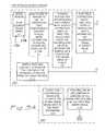
- FIG. 1is a block diagram showing the invention and the specifics related to the various functions.
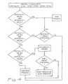
- FIG. 2is a block diagram showing the major steps for determining the accuracy and characteristics of the printed subject matter and the action as taken with respect to criticality.
- FIGS. 3A and 3Bare figures that are interconnected at interconnects (IC) and show the detailed block diagrams of the various methods and functions for reading and characterizing the printed subject matter as being of an acceptable standard.
- FIG. 4shows a logic diagram with regard to the criticality that is to be calculated of the respective values of the data read compared to the data which was to be printed.
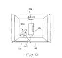
- FIG. 5shows a schematic view of the sensor lens and light source for reading the printed subject matter.
- FIG. 6shows a schematic diagram of the light source lens and photo sensors for reading the subject matter of the printed material.
- FIG. 7shows a block sequential diagram of the respective image sensing method.
- FIG. 8shows a side elevation view of a thermal printer which incorporates this invention.
- FIG. 9shows a detailed view of the print head, platen, and reading module as encircled by circle 9 of FIG. 8 .
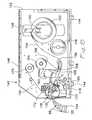
- FIG. 10shows a fragmented perspective view of the thermal printer in an open position as generally seen in the side elevation view of FIG. 9 .
- FIG. 11shows a simplified view of the data stream transfer.
- FIG. 12shows a method and process block diagram of the data stream.
- FIG. 13shows a schematic view of the data stream handling on an enlarged basis.
- FIG. 14shows a plan view of multiple text and bar codes being printed and the respective print area and read area pertaining thereto.
- FIG. 15shows the ability to determine proper placement of the print on the label.
- FIG. 16shows the placement of the label within the realm of a given set of parameters.
- FIG. 17shows a profile of the scan which is taking place and the handling of the data.
- FIG. 18shows the system and process of calculating a respective blemish on printed subject matter.
- FIG. 19shows the system and process for calculating the defects through the white and black characteristics of the printed subject matter.
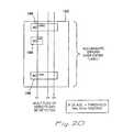
- FIG. 20shows the method and process of accumulating errors over an entire label which has multiple printed subject matter.
- FIG. 21shows the logic process and method for handling the bar code once read.
- FIG. 1shows the overall system and process for reading the printed subject matter and comparing it with the proper data to be printed.
- the printeris usually such where it has an internal printer controller 110 .
- the printer controller 110is within a printer 114 as seen on a schematic basis within the block labeled as such.
- the printer 114can be any printing mechanism or any particular printer engine which is compatible with the processes and methods to provide the read after print correlation of this invention.
- the printer 114can be controlled by the printer controller and receive signals from a host or host system 116 providing data or other information for controlling the printer 114 through the printer controller 110 .
- This host 116can be part of a system that has been placed in series or in parallel with other printers.
- the printer 114 in this particular caseis shown as a thermal printer. However, the printer can be a laser printer, line printer, or various impact printers driven by its respective printer engine.
- the thermal printer 114has a print head 118 which has a number of heated dot or pixel areas. The heated dots dispose a waxy substance on a print ribbon in order to place the respective dots on the media which is passing thereunder.
- a platen 120Underlying the print head 118 is a platen 120 that rotates by means of a drive means such as a belt 122 or other linkage driven by a stepper motor 124 .
- a drive meanssuch as a belt 122 or other linkage driven by a stepper motor 124 .
- One of the controlling factors to the printing systemis to provide the media moving between the print head 118 and the platen 120 as the stepper motor turns.
- the movement of the stepper motoris key to allowing for a sufficient time related to the heating of the respective dots by the print head 118 which this invention serves to control as well as a multitude of other functions.
- a print head tap 126receives data from the printer controller 110 in the nature of the printed subject matter. This print head tap 126 provides the data to the read after print (RAP) or RAP controller 128 .
- An image sensing module, or imager 130provides information to the read after print (RAP) controller 128 as to the respective placement and quality of the image seen from the printed subject matter after it is printed by the print head 118 .
- the description shown as to the paper path in a thermal printeris actually the path of the carrier or liner with the media such as plastic labels which are to be printed thereon.
- This printable media with the liner or carriercan be transferred to another process.
- the labelscan then be stripped for providing them to another area utilizing them in a particular process or stripped from the carrier or liner for later use, or stored.
- FIG. 1shows that the read after print (RAP) controller 128 functions or performs processes in a manner as detailed further in FIG. 2 .
- Thisprovides the functions or processes of read head information (B).
- the RAP controller 128also provides collectively read image information, read paper velocity, synchronizing of image capture with velocity, rotating and translating the image to the bit map, and interpolating the image chip tile gaps all labeled in box (A).
- the RAP controller 128with its processor compares printed pixels to those commanded pixels to the print head (D).
- the RAP controller 128also performs label analysis to determine the criticality of blemishes and weigh them against a pre-established standard to provide appropriate output results shown in the box labeled (C, E, and F).
- Such functions or processes as shown in portion (A) of the RAP controller 128can determine when the print head 118 is not properly aligned. It can also determine gaps in the printed material and accurately fund the edges of the respective gaps to determine the accuracy of print position.
- the functions or processes of (C, E, and F)can provide a permanent output. Processes of (C, E, and F) can also weigh the aspects thereof or indicate them to a downstream process which uses the data or image such as in a bar code that has been printed.
- FIG. 2it can be seen that the functions or processes of (A), (B), (C), (D), and (E) on the higher level provide for the foregoing functions.
- This higher level function or processallows the function for instance of acquiring and aligning the image (A). In this manner, the image is rotated as well as aligned in order to determine whether it is properly placed on the labels.
- Function or process (B)is such where the reference data is read. Once the reference data is read, it passes the reading to function or process (D) to match the image component and find the matched grouping in process (E).
- the foregoing information or datais then weighed with regard to criticality for action thereafter.
- the weight of the criticalityis dependent upon the net result that is desired as far as the quality is concerned of the printed subject matter. This quality factor can be specified by a customer or the end usages for which the printed subject matter is to be used.
- the reading of a bar code or other printed subject mattercan be easily undertaken at levels demanding less criticality and quality of printed subject matter.
- the criticalitycan be established as to the weightings determined by “a” as seen in the weighing example of FIG. 2 .
- This criticalitycan be established through look-up tables in the printer controller 110 or within the host system 116 . It can also be modified depending upon the requirements for end use of the subject matter.
- the measured errors and criticality levelare based upon a predetermined criteria that is selected based upon the application or end usage of the label such as a bar code.
- the way the criteria and resultant data is weighedis through the established criticality absolute values, for example C 1 through C 5 as seen in FIG. 2 . These values C 1 through C 5 depending upon an end use are then weighed through relative weights al through a 5 . Fundamentally, the absolute values C 1 through C 5 are multiplied by the weightings which could possibly be a certain percentage based upon end use, or customer requests for the downstream process. This provides for the criticality shown in criticality examples 1, 2, and 3. A high range of numbers stops the process, a mid range of numbers would possibly allow a continuation if read, and a low range of numbers if detectable but consistently bad would also stop the process.
- the input to the criticality exampleis such wherein: the bar code BC is readable C 1 , the text valid is readable but not as clearly as desired C 2 , the user text is valid and corresponds to the pixel images C 3 , the graphics are valid which might be in the form of a particular graphic representation C 4 , and the general format is valid as to placement and other characterizations C 5 .
- FIGS. 5 , 6 , 7 , 8 , 9 , and 10it can be seen that the mechanical and electrical showings and graphic showings of the thermal printer that can utilize this invention have been shown.
- FIG. 8it can be seen that a thermal printer 140 is specifically shown for the printer 114 .
- the thermal printer 140comprises a case 142 seated on posts or pads 144 .
- the side elevation of FIG. 8shows a hinge 146 which allows a cover to be emplaced over the working mechanism of the printer.
- a bracket 148is shown for supporting a media support rod 150 for a spool of media 152 .
- the spool of media as unwoundis seen as the strip 154 . It is a combined strip for printing upon with an underlying carrier or liner 155 .
- the media 154can have a plurality of variously sized labels to be printed upon in various configurations on an underlying paper or other type of liner or carrier 155 .
- Such labelscan be receiving documents, stocking labels, bin labels, picking documents, pallet labels, multi-part shipping documents, manifests, bills of lading, and reports.
- the media 154 forming the labelsis passed under a tensioning foot 156 having a pivotal support 158 .
- the foot 156can travel upwardly and downwardly to maintain tension on the media 154 .
- the media 154is passed to a print head support bracket 160 .
- the print head support bracket 160has a print head which will be detailed hereinafter in the form of print head 118 .
- the print head 118is comprised of a number of heated pixels or dots which heat a wax, plastic, or other type of print ribbon.
- This ribboncan be seen in the form of a print ribbon roll 164 from which the print ribbon 166 is unwound and maintained in tension by a floating rod, roller, or bar 168 .
- As the print ribbon 166 passes toward the print head 118it allows for the placement of pixels or dots being printed on the media 154 .
- the media and the print ribbonare supported by a rotating platen 120 that is underlying the print head 118 .
- the print ribbon 166After the print ribbon 166 has placed and printed appropriate pixels or other marks on the media 154 , it then passes to a windup spool 170 .
- the passage of the used print ribbon 66is over a head 172 that can be a floating head or a spring loaded head for adjusting the pressure and floating movement of the print ribbon 166 thereover.
- a rewinder 176is shown for winding the labels back.
- a bottom support 178is utilized for supporting the structure including the platen and the drive mechanism.
- a lever 180 with a securement latchcan allow for connection and receipt of the print head bracket 160 .
- the reading process after printingis accomplished by means of a read after print mechanism or imager 130 that will be detailed hereinafter.
- the material that is to be readis the printing on labels such as labels 186 of various sizes that form the media 154 with the underlying carrier or liner 155 .
- FIG. 10it can be seen that the print head 118 , platen 120 , read after print module 184 or imager 130 and the other elements have been shown in an open position for receipt of the media 154 and print ribbon 166 for placement therein to subsequently feed it through for a printing process.
- the media 154 and the print ribbon 166are passed under the print head 118 and over the platen 120 .
- the 120is driven by the motor 124 connected thereto.
- the speed of the motor turning the platenis determined by the method and process of this invention.
- a wheel 190is shown.
- the wheelcan be automatically driven or indexed depending upon the input of a stepper motor which drives the wheel.
- the wheelturns to provide movement to lead screws attached to blocks 192 and 194 that move the pressure point of the print head 118 along and over the platen 120 .
- a spring 196is shown wound around a rod support 198 .
- a seating inset in the form of a bracket 200is shown which cooperates to sit over the platen 120 without binding its movement.
- the bracket 200with its semi-circular concavity also serves to register the print head 118 over the platen 120 .
- a roller 204is shown for passing the print media 154 with its respective labels 186 thereover.
- the print media 154 with the liner or carrier 155passes over the roller 204 so that the labels can be placed in a position for reading by a read head 210 .
- the read head 210is held in place by a locking tab 212 which displaces the side walls of a concavity 214 to seat therein.
- a lens array or grouping of lenseswhich will be detailed hereinafter is placed under a clear cover 217 .
- a further array of light emitting diodes 220is used to provide a light source.
- the entire read after print head 210is hinged to a hinge point 224 for lifting and lowering it onto the base thereof.
- Appropriate handling of the media 154 with labels 186can be such where it comes into close proximity for reading through the cover 217 by means of a second roller 205 .
- the second roller 205effectively works with the other roller 204 in order to place the media 154 with the labels 186 in close proximity for reading.
- the LED array 220has been shown with an LED 230 .
- the LED array 220is spaced at eight LED's 230 to the inch.
- the LED array 220is mounted so as to cast a light on the labels 186 as well as the media 154 and carrier 155 .
- This light on the specific labels 186is reflected and captured by a series of gradient index lenses 232 .
- the gradient index lenses 232can be derived from a doped piece of glass or provided as an individual array or lenses.
- the gradient index lens (GRIN lens)in this case provides a one to one relationship. The one to one relationship of the image is then cast on to a sensor array 234 of a plurality of photo or light sensors.
- An edge removal member 238is shown for removing the print ribbon 166 from the media 154 so that it can then be rolled up on the roll 170 .
- any other means for handling the print ribbon 166can be utilized.
- the orientation of the LED array 220is such where it casts a light in the form of a light source or beam 242 onto the label 186 that is to be read as well as the media 154 and carrier 155 .
- the one to one GRIN lens 232then transmits the beam 242 to the light sensor array 234 .
- This GRIN lensis fundamentally a rod lens having multiply doped areas so that it focuses the output of the reflected light 242 to the photo sensors 234 .
- the LED'scast a light that is received by the photo sensors 234 that are approximately six hundred (600) to the inch but can be twelve hundred (1200) to the inch or more depending upon the resolution desired. The higher resolution the more the aspects of each particular pixel can be analyzed as to its gray scale nature.
- a shift register 251is utilized as well as a buffer 254 .
- the buffer 254has a clock pulse (CP) and a synchronization pulse (SP) to provide for the output and provide for the output on a synchronous and clocked basis from the shift register.
- a ground (GRD)is provided with appropriate outputs from amplifiers 1 , 2 , 3 , and 4 to voltage outputs 1 , 2 , 3 , and 4 to a multiplicity of voltage outputs M.
- the photo sensors 234can be ranked, or grouped from 1 through a given number and spaced for density depending upon the degree of resolution that is required in order to determine the gray scale and quality of the printed subject matter.
- the array of LED's 220 , GRIN lenses 232 , and the photo sensors 234provide an output of the reflected light that can be reviewed and read as the beam of light 242 is passed to the sensors 234 .
- the image sensing module 130 block diagramincorporates the gaps of the sensors 234 at less than one pixel.
- the sensing module sensors 234 or photo sensors M ⁇ Nis greater in density than the number of M ⁇ N pixels. This provides an overlap in density such that the sensors 234 are gapped so as to be less than one pixel. In this manner, they are able to capture pixels without skipping any dark material within the gray scale.
- FIG. 11shows the data stream from the printer including the printer controller 110 and the host system 116 .
- This data streamis provided to the print head 118 as a data stream 260 .
- the data stream 260 to the print head 118is tapped off as seen in FIG. 11 as well as the data from the information received from the read after print imager 130 .
- the data stream 260 and the readings of the imager 130are then processed in the read after print (RAP) or controller 128 shown in FIG. 12 .
- the image content from the imager 130is delivered to the RAP controller or RAP 128 and the signals to the printer head in the form of data stream 260 are presented to the RAP 128 for comparison sake. The same scheme is seen in FIG. 13 .
- FIGS. 3A and 3Bit can be seen that they set forth the detailed block diagram of the read after print (RAP) 128 method and process of this invention.
- FIG. 3Ahas been split between two sheets and is interconnected by the respective interconnects IC.
- FIG. 3Bhas also been split into two sheets and is interconnected by the interconnects IC shown therewith.
- the dotted and blocked out portion (A)shows the image sensor or module in the form of the image sensor 130 receiving the images through the sensors 234 of the number of M ⁇ N sensors. This is derived from the array of elements of the sensors 234 ( 1 ).
- the output of the multiplicity of sensed datais then processed with analog to digital A to D convertors that continuously convert the analog image information from the sensors 234 to a digital domain one scan line at a time ( 2 ).
- the one scan line at a timeis with respect to each line of pixels that has been printed.
- a processor or processors with appropriate storage, or memoryinterpolate each sample with respect to previous samples. It takes the two values and finds the interpolated value in between the sample data points for determining the linear array of pixels that are being printed ( 3 ).
- This process under FIG. 3A (A)uses a processor or analogous hardware and/or firmware such as or analogous to a Field Programmable Gate Array (FPGA) processes.
- the FPGAis connected for receipt of the data from the photo sensors 234 .
- Flat field correctionis then incorporated in order to smooth out the discrepancies in the field in order to provide for a smooth line.
- various intensity values of high and loware combined to provide a line of flat field correction ( 4 ).
- a rotation system or methodtransforms the image into the print head's coordinate system through a rotation system so that it is in proper alignment. In this manner, it takes the image as sensed and rotates it into a proper bit map orientation for the read head or imager 130 .
- the informationis then digitized by a digitizer that converts an image from gray scale to binary data on a line by line basis ( 7 ).
- a velocity compensation system in the processorwhich in this case would be the FPGA continuously corrects for the liner, carrier 155 , or label or media 154 velocity and generates a scan line delay that corresponds to the line sampling resolution of the image. In this manner, the particular velocity of the media 154 and carrier 155 is accounted. This generates a scan line that corresponds to the proper line of sampling and resolution of the image. This is the velocity-compensation system ( 6 ).
- the foregoing functionscorrespond to the acquisition and alignment of the image function (A) as shown in FIG. 2 .
- the print head informationis derived from a data stream 260 that allows a continuous reading and extracting of the bit map image being sent to the print head 118 , ( 12 ). Thereafter, a line by line component labeling of the non-zero regions of the captured binary image are provided for ( 13 ). The center of mass of the particular image is calculated as to both qualities of area and gray scale content.
- the stepper motor 124 control signals ( 14 )are input to the velocity compensation system and processor. Additionally, it can be seen in block ( 15 ) a component labeling function is performed of all non-zero regions of the digitized image in order to control the respective characterization of the images ( 15 ).
- the decoded regions provided in dotted line block (C)uses the decoded regions to determine and analyze the coordinates. It takes the gray scale data to determine various parameters ( 10 ) including those established for American National Standards Institute (ANSI). Thus, a check of the decoded text in (C) is undertaken for processing and determining the quality of the printed subject matter against a given set of values and a look-up table.
- the functions within the dotted lines of block (C)can be processed by a processor such as a common Digital Signal Processor DSP which is known in the art. This DSP can be a single DSP or provided among a series of DSP's.
- OCRoptical character recognition
- the determination of the angular offsetis such wherein a compensation can then be made as to providing for accuracy of reading in the event that a particular portion is rotated in an offset manner that would not provide for the true reading of it.
- the velocity using the edges of small objects in the digitized imageallows for control of the movement of the stepper motor 124 and the platen 120 to which it is connected.
- the features to match up with the bit mapare such wherein they can then make a comparison for purposes of determining accuracy of the printed subject matter with that which was to be printed by reviewing the tapped off information from the data sent to the print head 118 in comparison to the image actually seen.
- This function as can be seen in process ( 23 )is a major function under dotted line process (E) for the weighing of criticality as to the degree of correctness of the printed subject matter through the finding and matching of the groupings as seen in FIG. 2 .
- the input from ( 5 )which relates to the rotation system that transforms the line sensor's image into the print head's coordinate system helps with respect to the detection of the edges of the form or the subject matter to be printed on the labels 186 . It should be understood that if the edges of the form on the label 186 are not accurate with regard to the media as opposed to the underlying liner or carrier 155 and it is off the edge, or in the alternative that the edge of the form is not centered correctly on the media, that improper printing will take place. This has to be verified through the process of detecting the edges of the form ( 25 ).
- a determination of the position of the printed groupings relative to the edgesis undertaken. This determination of the groupings relative to the edges is enhanced by the input of also using the predetermined collections of features and groupings ( 23 ).
- the input with regard to the extracted component features to determine if they match features extracted from the bit map excluding the bar codes ( 22 )is provided as an input in the process for weighing the respective elements and data of the printed subject matter ( 24 ).
- Thisis the function by the processor in the form of the Digital Signal Processor as established with respect to a look up table. This is also. illustrated in FIG. 2 as to the weighing and criticality, and the taking of action with respect to the determination (F).
- the extracted features process ( 20 )does not necessarily input the bar code. They have already been analyzed and can be either input or not depending upon the process.
- C 1 , C 2 , C 3 , C 4 , and C 5that respectively relate to bar code validity, text validity, user text validity, graphics validity, and the general format are weighed for their criticality in the process (F) as shown.
- actionis taken depending upon the quality of the printed subject matter. In other words, if the media 54 , discrete label 86 , or other material upon which the printing takes place, is such where the bar code can't be read, the process is stopped. If the bar code is below a preset threshold, the process can also be stopped. Also, if the code is consistently bad, the process can be stopped.
- FIG. 4a logic table for maintaining or stopping the process is shown. It should be understood that the process can be verification of a properly printed format, utilization of the properly printed format, or emplacement of the printed material on another underlying material or in a subsequent process such as an inline manufacturing process or labeling of various boxes and components from a series of multiply printed labels.
- the first analysis in the processis if the criticality is less than a first given value and the criticality is greater than a second given value the process is then stopped. If not, the printing process goes on to determine whether or not a pre-established number as to criticality is less than the second value and whether or not the criticality is greater than a third value. If yes, the criticality will be tested as to whether it is greater than a preset threshold, if not, the process will be stopped. The next analysis in the process is whether the criticality is less than a third value and greater than a fourth value, if not, the process will continue.
- the continuation of the process automatically or the alerting of the operatortakes place when the sum exceeds a preset threshold.
- preset thresholdscan be established within the look-up table or any other process in both the feedback to the printer controller 110 or the host system 116 .
- the host system 116can handle a plurality of printers in which labels are being extracted from various printing processes to be placed on various packages, goods, manufactured items to be assembled, and any other particular grouping of goods or equipment which is to be labeled and later read or labeled and maintained in a subsequently labeled relationship.
- FIG. 15it can be seen wherein a label 186 is emplaced on the liner or the carrier 155 , which underlies a portion of the media 154 forming the labels to be printed upon.
- FIG. 15shows a detection of the edges of the labels 186 through a horizontal profiling.
- the determination of the edge of the label 186is important with respect to assuring the printed subject matter does not overlap the label. It is also important in some cases for centering the subject matter to determine whether it is within the border or margin, in a properly positioned relationship. This is done by determining the intensity value.
- the intensity value of the label 186is differentiated from the carrier 155 as determined by gray scale imaging.
- the gray scale imaging and intensity value of the upper level and lower gray scale value of the lower levelis determined to effect an edge reading. Due to the fact that the label 186 moves along at a particular rate, the calculation is performed so that if the area is bigger, an error indication is established. Fundamentally, the edge region is established through the gray scale differentiation as shown with the high and low aspects so that a value A has an upper value and a value B has a lower value. This particular intensity value establishes the edge region of the label so that a calculation of the edges for proper print and placement of the print with respect to the edges of the label can be effected.
- FIG. 16it can be seen where the media and liner combination for detecting the edges has been shown with the higher value A and the lower value B as to the respective gray scale.
- the printed subject matteris calculated with respect to the spread of the gray scale so that the edges are consistent with regard to the placement of the printed subject matter on the label 186 .
- FIG. 17shows the defect analysis of a single scan line.
- D 1 and D 2indicate a light area and a dark area respectively. These respective light and dark areas are analyzed to provide for a bar code profile of one scan.
- the scan lineis at twice the printing resolution, in order to allow for overlap and inclusion of the spread of the particular printed subject matter.
- the light area defect D 1 and the dark area defect D 2are determined on a single scan at two times the printing resolution to check the overlap.
- the particular defectis established as to criteria based upon end uses such as whether the bar code or printed subject matter is to be read in a retail process or a refined inline manufacturing process wherein various criticalities and weighings must be established.
- FIGS. 18 and 19it can be seen wherein a constant defect is persistent in a bar code.
- the defectcan also be with regard to a particular graphic element.
- the defectis seen in a bar code.
- the bar codeis used to find defect positions and then using the principle of inverse voting at these locations.
- FIG. 20it can be seen where the errors are accumulated over a series of entire multiple labels and the multitude of defects detected.
- the defectscan be in a scan line such as defects D 1 , D 2 , and D 3 .
- the defects along an entire series of labels 186 on the underlying carrier or liner 155are recurrent.
- the errorsare accumulated over the entire label and a determination is made as to whether or not a pixel or printing dot is defective.
- Such defectscan be within a print head of a thermal printer where the element is burnt or stuck.
- criticality 3 in the weighing and criticality action (F)is shown as being established so that there is a consistently bad label 186 and the process is stopped.
- the thresholdcan be established as previously stated under any criteria. However, as can be appreciated with a burnt or stuck pixel or thermal printing dot defect the consistency would then be manifest and the entire process should then be stopped.
- FIG. 21shows the reading of a scan line. If a bar code is found, it then goes on to check whether a defect has been found. This defect is with respect to C 1 of FIG. 2 as to the validity of a bar code.
- the defectcan be established within the American National Standards Institute (ANSI) qualification or other bar code standard that can be established based on end use. If the defect is an ANSI or other defect grade, the position and offset is used for investigating subsequent scans. The inverse voting method of the previous process is established and an accumulation of the error at the location thereafter. If the accumulated error is greater than the threshold value, i.e. C 1 , a failure flag C 1 or C 5 depending upon the user setup is established. If not, the read scan mode continues with regard to ANSI or other standards.
- ANSIAmerican National Standards Institute
- any processor or series of processorscan be utilized.
- the Field Programmable Gate Array(FPGA) has been used for processing the methods and processes labeled (A) and (B).
- the Digital Signal Processor DSPis used for the methods and processes labeled (C) (D) (E) and (F).
- any other combination or processors, storage, or other signal bufferscan be implemented.
Landscapes
- Record Information Processing For Printing (AREA)
- Accessory Devices And Overall Control Thereof (AREA)
- Printers Characterized By Their Purpose (AREA)
- Dot-Matrix Printers And Others (AREA)
Abstract
Description
Claims (12)
Priority Applications (1)
| Application Number | Priority Date | Filing Date | Title |
|---|---|---|---|
| US10/850,420US7891892B2 (en) | 2002-08-14 | 2004-05-20 | Printer read after print correlation method |
Applications Claiming Priority (2)
| Application Number | Priority Date | Filing Date | Title |
|---|---|---|---|
| US10/218,834US6896428B2 (en) | 2002-08-14 | 2002-08-14 | Printer read after print correlation method and apparatus |
| US10/850,420US7891892B2 (en) | 2002-08-14 | 2004-05-20 | Printer read after print correlation method |
Related Parent Applications (1)
| Application Number | Title | Priority Date | Filing Date |
|---|---|---|---|
| US10/218,834DivisionUS6896428B2 (en) | 2002-08-14 | 2002-08-14 | Printer read after print correlation method and apparatus |
Publications (2)
| Publication Number | Publication Date |
|---|---|
| US20040213617A1 US20040213617A1 (en) | 2004-10-28 |
| US7891892B2true US7891892B2 (en) | 2011-02-22 |
Family
ID=31714617
Family Applications (6)
| Application Number | Title | Priority Date | Filing Date |
|---|---|---|---|
| US10/218,834Expired - Fee RelatedUS6896428B2 (en) | 2002-08-14 | 2002-08-14 | Printer read after print correlation method and apparatus |
| US10/850,551Expired - LifetimeUS6997627B2 (en) | 2002-08-14 | 2004-05-20 | Label printer read after print correlation apparatus |
| US10/850,210AbandonedUS20040213616A1 (en) | 2002-08-14 | 2004-05-20 | Label printer read after print correlation apparatus |
| US10/850,549AbandonedUS20040212836A1 (en) | 2002-08-14 | 2004-05-20 | Printer read after print correlation apparatus |
| US10/850,604Expired - LifetimeUS7646498B2 (en) | 2002-08-14 | 2004-05-20 | Thermal printer read after print correlation apparatus |
| US10/850,420Active2027-02-02US7891892B2 (en) | 2002-08-14 | 2004-05-20 | Printer read after print correlation method |
Family Applications Before (5)
| Application Number | Title | Priority Date | Filing Date |
|---|---|---|---|
| US10/218,834Expired - Fee RelatedUS6896428B2 (en) | 2002-08-14 | 2002-08-14 | Printer read after print correlation method and apparatus |
| US10/850,551Expired - LifetimeUS6997627B2 (en) | 2002-08-14 | 2004-05-20 | Label printer read after print correlation apparatus |
| US10/850,210AbandonedUS20040213616A1 (en) | 2002-08-14 | 2004-05-20 | Label printer read after print correlation apparatus |
| US10/850,549AbandonedUS20040212836A1 (en) | 2002-08-14 | 2004-05-20 | Printer read after print correlation apparatus |
| US10/850,604Expired - LifetimeUS7646498B2 (en) | 2002-08-14 | 2004-05-20 | Thermal printer read after print correlation apparatus |
Country Status (4)
| Country | Link |
|---|---|
| US (6) | US6896428B2 (en) |
| EP (1) | EP1400362B1 (en) |
| CN (1) | CN100346985C (en) |
| DE (1) | DE60336878D1 (en) |
Cited By (13)
| Publication number | Priority date | Publication date | Assignee | Title |
|---|---|---|---|---|
| WO2013059551A1 (en)* | 2011-10-20 | 2013-04-25 | Source Technologies, Llc | Top of form sensor |
| US8687032B2 (en) | 2011-06-06 | 2014-04-01 | Datamax-O'neil Corporation | Printing ribbon security apparatus and method |
| US8730287B2 (en) | 2011-06-24 | 2014-05-20 | Datamax-O'neil Corporation | Ribbon drive assembly |
| US8736650B2 (en) | 2011-06-23 | 2014-05-27 | Datamax-O'neil Corporation | Print station |
| US8810617B2 (en) | 2011-06-24 | 2014-08-19 | Datamax-O'neil Corporation | Apparatus and method for determining and adjusting printhead pressure |
| US8842142B2 (en) | 2011-08-05 | 2014-09-23 | Datamax-O'neil Corporation | Print station system |
| US8842143B2 (en) | 2011-08-05 | 2014-09-23 | Datamax-O'neil Corporation | Printing system |
| US9024988B2 (en) | 2011-12-22 | 2015-05-05 | Datamax-O'neil Corporation | Media detection apparatus and method |
| US9061527B2 (en) | 2012-12-07 | 2015-06-23 | Datamax-O'neil Corporation | Thermal printer with single latch, adjustable media storage and centering assemblies and print assembly |
| US9193552B2 (en) | 2011-11-22 | 2015-11-24 | Datamax-O'neil Corporation | Synchronized media hanger/guide |
| US9219836B2 (en) | 2011-05-23 | 2015-12-22 | Datamax-O'neil Corporation | Sensing apparatus for detecting and determining the width of media along a feed path |
| US9481186B2 (en) | 2011-07-14 | 2016-11-01 | Datamax-O'neil Corporation | Automatically adjusting printing parameters using media identification |
| US9676216B2 (en) | 2014-03-27 | 2017-06-13 | Datamax-O'neil Corporation | Systems and methods for automatic printer configuration |
Families Citing this family (26)
| Publication number | Priority date | Publication date | Assignee | Title |
|---|---|---|---|---|
| DE60129718T2 (en) | 2000-09-11 | 2008-04-30 | Zipher Ltd. | BAND DRIVE AND PRESSURE DEVICE |
| US7028009B2 (en)* | 2001-01-17 | 2006-04-11 | Contentguardiholdings, Inc. | Method and apparatus for distributing enforceable property rights |
| US6896428B2 (en) | 2002-08-14 | 2005-05-24 | Printronix, Inc. | Printer read after print correlation method and apparatus |
| US7066668B2 (en)* | 2003-12-10 | 2006-06-27 | Ncr Corporation | Method of creating an image replacement document for use in a check truncation environment and an apparatus therefor |
| GB2416237A (en)* | 2004-07-12 | 2006-01-18 | Markem Tech Ltd | Method of printing |
| US7066669B2 (en)* | 2004-08-30 | 2006-06-27 | Ncr Corporation | Method of creating an image replacement document for use in a check truncation environment and an apparatus therefor |
| CN100369106C (en)* | 2004-12-17 | 2008-02-13 | 虹光精密工业(苏州)有限公司 | Variable speed adjustment device and adjustment method for digital set value |
| JP4670410B2 (en)* | 2005-03-16 | 2011-04-13 | ソニー株式会社 | Thermal head printer and printing method for thermal head printer |
| US20080156863A1 (en)* | 2006-12-29 | 2008-07-03 | Weyerhaeuser Co. | Systems and methods for improving the readability of printed bar code symbols and the like |
| GB2448302B (en) | 2007-03-07 | 2009-04-08 | Zipher Ltd | Tape drive |
| EP2134549B1 (en) | 2007-03-31 | 2014-11-19 | Videojet Technologies, Inc. | Tape drive |
| EP1977900B1 (en)* | 2007-04-03 | 2014-06-04 | Custom S.p.A. | Thermal printer head with print control device |
| US8934132B2 (en)* | 2012-05-08 | 2015-01-13 | Xerox Corporation | Systems and methods for implementing dynamic user intent-based imaging options in image forming and document handling systems |
| US8923571B2 (en)* | 2012-07-16 | 2014-12-30 | Hewlett-Packard Development Company, L.P. | Automated camera flat fielding and alignment |
| WO2016054523A1 (en)* | 2014-10-03 | 2016-04-07 | Avery Dennison | Customizable food freshness printer startup wizard |
| CN104553348B (en)* | 2014-12-19 | 2016-06-22 | 深圳市驰卡技术有限公司 | The card checking method of card puncher and card puncher |
| US10467513B2 (en) | 2015-08-12 | 2019-11-05 | Datamax-O'neil Corporation | Verification of a printed image on media |
| GB2568494B (en)* | 2017-11-17 | 2021-07-28 | Pyramid Innovation Ltd | A method of marking a laboratory sample carrier and checking the quality of the printing |
| US10546160B2 (en) | 2018-01-05 | 2020-01-28 | Datamax-O'neil Corporation | Methods, apparatuses, and systems for providing print quality feedback and controlling print quality of machine-readable indicia |
| US10834283B2 (en) | 2018-01-05 | 2020-11-10 | Datamax-O'neil Corporation | Methods, apparatuses, and systems for detecting printing defects and contaminated components of a printer |
| US10803264B2 (en) | 2018-01-05 | 2020-10-13 | Datamax-O'neil Corporation | Method, apparatus, and system for characterizing an optical system |
| US10795618B2 (en) | 2018-01-05 | 2020-10-06 | Datamax-O'neil Corporation | Methods, apparatuses, and systems for verifying printed image and improving print quality |
| CN110858248B (en)* | 2018-12-13 | 2023-03-24 | 安天科技集团股份有限公司 | Information security detection method and device for printing equipment |
| DE102019119500A1 (en)* | 2019-07-18 | 2021-01-21 | Leica Biosystems Nussloch Gmbh | Printer for printing on histology laboratory consumables |
| JP7304002B2 (en)* | 2019-09-24 | 2023-07-06 | ブラザー工業株式会社 | printer |
| CN115447289B (en)* | 2022-08-30 | 2024-04-30 | 苏州浪潮智能科技有限公司 | Label breakpoint compensation printing device and detection compensation method |
Citations (46)
| Publication number | Priority date | Publication date | Assignee | Title |
|---|---|---|---|---|
| US3199450A (en)* | 1963-10-15 | 1965-08-10 | William B Leavens | Method of inspecting labels to determine if such have been properly printed and cut |
| US4271476A (en)* | 1979-07-17 | 1981-06-02 | International Business Machines Corporation | Method and apparatus for rotating the scan format of digital images |
| US4587411A (en) | 1983-01-04 | 1986-05-06 | F & O Electronic Systems Gmbh & Co. | Method of printing, evaluating and checking the printing image of a printer and apparatus for carrying out said process |
| US4639287A (en)* | 1980-05-26 | 1987-01-27 | Tokyo Electric Co., Ltd. | Label feed control system |
| US4658366A (en)* | 1984-08-09 | 1987-04-14 | Posh David R | Methods and apparatus for accurately completing pre-printed forms |
| US4699531A (en) | 1984-11-30 | 1987-10-13 | Rjs Enterprises, Inc. | Self-correcting printer-verifier |
| JPS637955A (en) | 1986-06-30 | 1988-01-13 | Pfu Ltd | Bar code printing system |
| US4757537A (en)* | 1985-04-17 | 1988-07-12 | Pitney Bowes Inc. | System for detecting unaccounted for printing in a value printing system |
| US4762063A (en)* | 1987-01-23 | 1988-08-09 | Yeagle Paul H | Bar code printing method |
| US4775246A (en)* | 1985-04-17 | 1988-10-04 | Pitney Bowes Inc. | System for detecting unaccounted for printing in a value printing system |
| US4795281A (en) | 1984-11-30 | 1989-01-03 | Tohoku Ricoh Co., Ltd. | Self-correcting printer-verifier |
| US4813802A (en)* | 1986-09-04 | 1989-03-21 | Alcatel Business Systems Ltd. | Device for verifying if thermal printer is operating correctly |
| US4875174A (en)* | 1987-03-06 | 1989-10-17 | Print Things | Instant label printer for host computer |
| US5020112A (en)* | 1989-10-31 | 1991-05-28 | At&T Bell Laboratories | Image recognition method using two-dimensional stochastic grammars |
| WO1993003454A1 (en) | 1991-07-29 | 1993-02-18 | Gtech Corporation | Printer with read-after-write/print quality checking |
| US5267800A (en) | 1992-08-06 | 1993-12-07 | Comtec Informations, Inc. | Miniature, portable, interactive printer |
| US5286120A (en)* | 1987-09-30 | 1994-02-15 | Kabushiki Kaisha Toshiba | Data printing system with scanning of forms |
| US5478422A (en)* | 1993-09-16 | 1995-12-26 | B & H Manufacturing Company, Inc. | Computer controlled turret type labeling machine |
| US5498087A (en)* | 1994-08-10 | 1996-03-12 | Printronix, Inc. | Wide web compatible printer |
| US5564841A (en) | 1994-09-13 | 1996-10-15 | Intermec Corporation | System and method for dynamic adjustment of bar code printer parameters |
| US5625399A (en)* | 1992-01-31 | 1997-04-29 | Intermec Corporation | Method and apparatus for controlling a thermal printhead |
| US5708462A (en) | 1988-06-22 | 1998-01-13 | Monarch Marking Systems, Inc. | Microprocessor controlled thermal printer |
| US5729637A (en)* | 1994-08-31 | 1998-03-17 | Adobe Systems, Inc. | Method and apparatus for producing a hybrid data structure for displaying a raster image |
| US5803624A (en) | 1995-08-31 | 1998-09-08 | Intermec Corporation | Methods and apparatus for compensatng step distance in a stepping motor driven label printer |
| US5816164A (en)* | 1994-04-20 | 1998-10-06 | Heidelberger Druckmaschinen Ag | Method and apparatus for monitoring image formation on a printing form |
| US5823693A (en)* | 1995-11-30 | 1998-10-20 | Intermec Ip Corp. | Gapless label media and printing apparatus for handling same |
| US5915865A (en)* | 1996-12-05 | 1999-06-29 | Intermec Ip Corp. | Method and apparatus for compensating for printer top-of-form and image stretch errors |
| EP0932111A2 (en) | 1998-01-22 | 1999-07-28 | Intermec Ip Corp. | Method and apparatus for printing a symbol with real-time print quality correction |
| US6023284A (en)* | 1996-04-03 | 2000-02-08 | Intermec Ip Corporation | Method and apparatus for the maximization of print quality in a multipass thermal printer ribbon |
| US6028674A (en) | 1996-05-23 | 2000-02-22 | Sun Microsystems, Inc. | Consumer-document inking monitor and control |
| EP1085452A2 (en) | 1999-09-14 | 2001-03-21 | Printronix, Inc. | Bar code verification and printing system |
| US6283647B1 (en)* | 1999-03-30 | 2001-09-04 | Seiko Epson Corporation | Bar code printer that automatically sets one bar color in response to another bar color |
| US6340255B1 (en) | 1999-01-21 | 2002-01-22 | Seiko Epson Corporation | Tape printing method to allow for removal of excess tape in a background environment |
| US6354503B1 (en) | 2000-06-21 | 2002-03-12 | Rjs Systems International | Bar code online scanner/verifier |
| US6357942B1 (en) | 2000-08-24 | 2002-03-19 | Lexmark International, Inc. | Method for reducing cyclic print errors |
| US6461064B1 (en)* | 1996-09-10 | 2002-10-08 | Benjamin Patrick Leonard | Service station assembly for a drum-based wide format print engine |
| US20020176730A1 (en) | 2001-05-14 | 2002-11-28 | Frederick Bleckmann | Method and apparatus for production of labels |
| US20020181021A1 (en)* | 2001-05-30 | 2002-12-05 | Stephens Vance M. | Techniques for aligning images using page characteristics and image shifting |
| US6493110B1 (en) | 2000-04-05 | 2002-12-10 | Gregory B. Roberts | System and method for bar code rendering and recognition |
| US6498616B1 (en) | 1996-08-14 | 2002-12-24 | Oki Data Corporation | Print head having non-volatile memory and means for transmitting correction and inherent data |
| US20030043388A1 (en)* | 2001-08-31 | 2003-03-06 | International Business Machines Corporation | Manually operated digital printing device |
| US6666593B2 (en) | 2001-06-26 | 2003-12-23 | Seiko Epson Corporation | Tape printing apparatus and image forming method and label producing method for the tape printing apparatus |
| EP1400362A2 (en) | 2002-08-14 | 2004-03-24 | Printronix, Inc. | Printer and print correlation method |
| US20040059541A1 (en)* | 2002-09-24 | 2004-03-25 | Satoru Oishi | Position detecting method and apparatus |
| US20040057768A1 (en)* | 2002-09-20 | 2004-03-25 | Tohoku Ricoh Co., Ltd. | Mark printing/verifying device, mark printing/verifying method and mark printing control method |
| US6735484B1 (en)* | 2000-09-20 | 2004-05-11 | Fargo Electronics, Inc. | Printer with a process diagnostics system for detecting events |
Family Cites Families (22)
| Publication number | Priority date | Publication date | Assignee | Title |
|---|---|---|---|---|
| JPH0654143A (en)* | 1992-07-28 | 1994-02-25 | Minolta Camera Co Ltd | Image forming device |
| WO1995000337A1 (en)* | 1993-06-17 | 1995-01-05 | The Analytic Sciences Corporation | Automated system for print quality control |
| DE69417319T2 (en)* | 1993-08-30 | 1999-07-15 | Hewlett-Packard Co., Palo Alto, Calif. | Image scanning head for a thermal inkjet printer |
| US5965862A (en)* | 1994-10-18 | 1999-10-12 | Seiko Epson Corporation | Information detection apparatus and method for printing on a medium and for reading information recorded on the medium |
| US5828406A (en)* | 1994-12-30 | 1998-10-27 | Eastman Kodak Company | Electronic camera having a processor for mapping image pixel signals into color display pixels |
| US6036091A (en)* | 1995-12-19 | 2000-03-14 | Webscan, Inc. | Method and apparatus supporting high speed evaluation of bar code indicia |
| FR2754371B1 (en) | 1996-10-04 | 1998-12-11 | Sagem | GAME TAKING TERMINAL |
| US6170747B1 (en)* | 1997-08-29 | 2001-01-09 | Jacob P. Meyer | Apparatus for inspecting print quality of barcodes on a high speed moving web |
| US6178009B1 (en)* | 1997-11-17 | 2001-01-23 | Canon Kabushiki Kaisha | Printing with multiple different black inks |
| JPH11353505A (en)* | 1998-06-10 | 1999-12-24 | Sankyo Seiki Mfg Co Ltd | Paper-like medium issuing device |
| US6358588B1 (en)* | 1998-10-03 | 2002-03-19 | Brady Worldwide, Inc. | Tags having a metallic heft and appearance and process for making them |
| US6137967A (en)* | 1999-09-13 | 2000-10-24 | Oce Printing Systems Gmbh | Document verification and tracking system for printed material |
| US6710895B1 (en)* | 1999-11-16 | 2004-03-23 | Cyberscan Technology, Inc. | Compact configurable scanning computer terminal |
| US7016064B2 (en)* | 1999-12-27 | 2006-03-21 | Fuji Photo Film Co., Ltd. | Method and system for remote management of processor, and method and system for remote diagnosis of image output apparatus |
| WO2001057600A1 (en)* | 2000-02-03 | 2001-08-09 | Estabrooks David A | On demand media web electrophotographic printing apparatus |
| US6592693B1 (en)* | 2000-08-11 | 2003-07-15 | Greydon Wesley Nedblake | Method and apparatus for laser cutting of adhesive-bearing webs separate from liner webs |
| EP1182607A1 (en)* | 2000-08-26 | 2002-02-27 | Hewlett-Packard Company, A Delaware Corporation | Method and device for improving image quality when printing on a media and related media profile |
| JP2002092399A (en)* | 2000-09-11 | 2002-03-29 | Olympus Optical Co Ltd | Printing order placing/receiving method, and printing order placing/receiving system, and information resource used for printing order placing/receiving system |
| US7046389B2 (en)* | 2001-04-04 | 2006-05-16 | Hewlett-Packard Development Company, L.P. | Variable density under/overprinting maps for improving print quality |
| US6498655B1 (en)* | 2001-06-01 | 2002-12-24 | Transact Technologies Incorporated | Self validating printer with ticket voiding and reprint features |
| US6609844B1 (en)* | 2001-11-09 | 2003-08-26 | Zih Corp. | Portable printer having automatic print alignment |
| JP2003319411A (en)* | 2002-04-19 | 2003-11-07 | Matsushita Electric Ind Co Ltd | Signal processor |
- 2002
- 2002-08-14USUS10/218,834patent/US6896428B2/ennot_activeExpired - Fee Related
- 2003
- 2003-07-09DEDE60336878Tpatent/DE60336878D1/ennot_activeExpired - Lifetime
- 2003-07-09EPEP03254353Apatent/EP1400362B1/ennot_activeExpired - Lifetime
- 2003-08-14CNCNB031540368Apatent/CN100346985C/ennot_activeExpired - Lifetime
- 2004
- 2004-05-20USUS10/850,551patent/US6997627B2/ennot_activeExpired - Lifetime
- 2004-05-20USUS10/850,210patent/US20040213616A1/ennot_activeAbandoned
- 2004-05-20USUS10/850,549patent/US20040212836A1/ennot_activeAbandoned
- 2004-05-20USUS10/850,604patent/US7646498B2/ennot_activeExpired - Lifetime
- 2004-05-20USUS10/850,420patent/US7891892B2/enactiveActive
Patent Citations (50)
| Publication number | Priority date | Publication date | Assignee | Title |
|---|---|---|---|---|
| US3199450A (en)* | 1963-10-15 | 1965-08-10 | William B Leavens | Method of inspecting labels to determine if such have been properly printed and cut |
| US4271476A (en)* | 1979-07-17 | 1981-06-02 | International Business Machines Corporation | Method and apparatus for rotating the scan format of digital images |
| US4639287A (en)* | 1980-05-26 | 1987-01-27 | Tokyo Electric Co., Ltd. | Label feed control system |
| US4587411A (en) | 1983-01-04 | 1986-05-06 | F & O Electronic Systems Gmbh & Co. | Method of printing, evaluating and checking the printing image of a printer and apparatus for carrying out said process |
| US4658366A (en)* | 1984-08-09 | 1987-04-14 | Posh David R | Methods and apparatus for accurately completing pre-printed forms |
| US4699531A (en) | 1984-11-30 | 1987-10-13 | Rjs Enterprises, Inc. | Self-correcting printer-verifier |
| US4795281A (en) | 1984-11-30 | 1989-01-03 | Tohoku Ricoh Co., Ltd. | Self-correcting printer-verifier |
| US4757537A (en)* | 1985-04-17 | 1988-07-12 | Pitney Bowes Inc. | System for detecting unaccounted for printing in a value printing system |
| US4775246A (en)* | 1985-04-17 | 1988-10-04 | Pitney Bowes Inc. | System for detecting unaccounted for printing in a value printing system |
| JPS637955A (en) | 1986-06-30 | 1988-01-13 | Pfu Ltd | Bar code printing system |
| US4813802A (en)* | 1986-09-04 | 1989-03-21 | Alcatel Business Systems Ltd. | Device for verifying if thermal printer is operating correctly |
| US4762063A (en)* | 1987-01-23 | 1988-08-09 | Yeagle Paul H | Bar code printing method |
| US4875174A (en)* | 1987-03-06 | 1989-10-17 | Print Things | Instant label printer for host computer |
| US5286120A (en)* | 1987-09-30 | 1994-02-15 | Kabushiki Kaisha Toshiba | Data printing system with scanning of forms |
| US5708462A (en) | 1988-06-22 | 1998-01-13 | Monarch Marking Systems, Inc. | Microprocessor controlled thermal printer |
| US5020112A (en)* | 1989-10-31 | 1991-05-28 | At&T Bell Laboratories | Image recognition method using two-dimensional stochastic grammars |
| WO1993003454A1 (en) | 1991-07-29 | 1993-02-18 | Gtech Corporation | Printer with read-after-write/print quality checking |
| US5625399A (en)* | 1992-01-31 | 1997-04-29 | Intermec Corporation | Method and apparatus for controlling a thermal printhead |
| US5267800A (en) | 1992-08-06 | 1993-12-07 | Comtec Informations, Inc. | Miniature, portable, interactive printer |
| US5478422A (en)* | 1993-09-16 | 1995-12-26 | B & H Manufacturing Company, Inc. | Computer controlled turret type labeling machine |
| US5816164A (en)* | 1994-04-20 | 1998-10-06 | Heidelberger Druckmaschinen Ag | Method and apparatus for monitoring image formation on a printing form |
| US5498087A (en)* | 1994-08-10 | 1996-03-12 | Printronix, Inc. | Wide web compatible printer |
| US5729637A (en)* | 1994-08-31 | 1998-03-17 | Adobe Systems, Inc. | Method and apparatus for producing a hybrid data structure for displaying a raster image |
| US6385350B1 (en)* | 1994-08-31 | 2002-05-07 | Adobe Systems Incorporated | Method and apparatus for producing a hybrid data structure for displaying a raster image |
| US5564841A (en) | 1994-09-13 | 1996-10-15 | Intermec Corporation | System and method for dynamic adjustment of bar code printer parameters |
| US5803624A (en) | 1995-08-31 | 1998-09-08 | Intermec Corporation | Methods and apparatus for compensatng step distance in a stepping motor driven label printer |
| US5823693A (en)* | 1995-11-30 | 1998-10-20 | Intermec Ip Corp. | Gapless label media and printing apparatus for handling same |
| US6019531A (en)* | 1995-11-30 | 2000-02-01 | Intermec Ip Corp. | Gapless label media and printing apparatus for handling same |
| US6023284A (en)* | 1996-04-03 | 2000-02-08 | Intermec Ip Corporation | Method and apparatus for the maximization of print quality in a multipass thermal printer ribbon |
| US6028674A (en) | 1996-05-23 | 2000-02-22 | Sun Microsystems, Inc. | Consumer-document inking monitor and control |
| US6498616B1 (en) | 1996-08-14 | 2002-12-24 | Oki Data Corporation | Print head having non-volatile memory and means for transmitting correction and inherent data |
| US6461064B1 (en)* | 1996-09-10 | 2002-10-08 | Benjamin Patrick Leonard | Service station assembly for a drum-based wide format print engine |
| US5915865A (en)* | 1996-12-05 | 1999-06-29 | Intermec Ip Corp. | Method and apparatus for compensating for printer top-of-form and image stretch errors |
| EP0932111A2 (en) | 1998-01-22 | 1999-07-28 | Intermec Ip Corp. | Method and apparatus for printing a symbol with real-time print quality correction |
| US6042279A (en)* | 1998-01-22 | 2000-03-28 | Intermec Ip Corporation | Method and apparatus for printing with real-time print quality correction, such as in one or two dimensional bar code printing |
| US6340255B1 (en) | 1999-01-21 | 2002-01-22 | Seiko Epson Corporation | Tape printing method to allow for removal of excess tape in a background environment |
| US6283647B1 (en)* | 1999-03-30 | 2001-09-04 | Seiko Epson Corporation | Bar code printer that automatically sets one bar color in response to another bar color |
| EP1085452A2 (en) | 1999-09-14 | 2001-03-21 | Printronix, Inc. | Bar code verification and printing system |
| US6535299B1 (en)* | 1999-09-14 | 2003-03-18 | Printronix, Inc. | Bar code verification and printing system |
| US6493110B1 (en) | 2000-04-05 | 2002-12-10 | Gregory B. Roberts | System and method for bar code rendering and recognition |
| US6354503B1 (en) | 2000-06-21 | 2002-03-12 | Rjs Systems International | Bar code online scanner/verifier |
| US6357942B1 (en) | 2000-08-24 | 2002-03-19 | Lexmark International, Inc. | Method for reducing cyclic print errors |
| US6735484B1 (en)* | 2000-09-20 | 2004-05-11 | Fargo Electronics, Inc. | Printer with a process diagnostics system for detecting events |
| US20020176730A1 (en) | 2001-05-14 | 2002-11-28 | Frederick Bleckmann | Method and apparatus for production of labels |
| US20020181021A1 (en)* | 2001-05-30 | 2002-12-05 | Stephens Vance M. | Techniques for aligning images using page characteristics and image shifting |
| US6666593B2 (en) | 2001-06-26 | 2003-12-23 | Seiko Epson Corporation | Tape printing apparatus and image forming method and label producing method for the tape printing apparatus |
| US20030043388A1 (en)* | 2001-08-31 | 2003-03-06 | International Business Machines Corporation | Manually operated digital printing device |
| EP1400362A2 (en) | 2002-08-14 | 2004-03-24 | Printronix, Inc. | Printer and print correlation method |
| US20040057768A1 (en)* | 2002-09-20 | 2004-03-25 | Tohoku Ricoh Co., Ltd. | Mark printing/verifying device, mark printing/verifying method and mark printing control method |
| US20040059541A1 (en)* | 2002-09-24 | 2004-03-25 | Satoru Oishi | Position detecting method and apparatus |
Non-Patent Citations (4)
| Title |
|---|
| Helmut Kipphan, Handbook of Print Media, 2001, p. 40. p. 310, p. 1115.* |
| IBM Technical Disclosure Bulletin, Shift Register Implemented Image Rotator Transposer, Jan. Mar, 1, 1975.* |
| IBM Technical Disclosure Bulletin, Shift Register System for Image Orientation, Jan. 1, 1976.* |
| Shimizu et al: "Read/Write LED Print Head" Apr. 1, 1997, pps. 15-18, vol. 63, No. 158, OKI Electric Industry, Tokyo, JP. |
Cited By (17)
| Publication number | Priority date | Publication date | Assignee | Title |
|---|---|---|---|---|
| US9219836B2 (en) | 2011-05-23 | 2015-12-22 | Datamax-O'neil Corporation | Sensing apparatus for detecting and determining the width of media along a feed path |
| US9079423B2 (en) | 2011-06-06 | 2015-07-14 | Datamax-O'neil Corporation | Printing ribbon security apparatus and method |
| US8687032B2 (en) | 2011-06-06 | 2014-04-01 | Datamax-O'neil Corporation | Printing ribbon security apparatus and method |
| US8736650B2 (en) | 2011-06-23 | 2014-05-27 | Datamax-O'neil Corporation | Print station |
| US8810617B2 (en) | 2011-06-24 | 2014-08-19 | Datamax-O'neil Corporation | Apparatus and method for determining and adjusting printhead pressure |
| US8730287B2 (en) | 2011-06-24 | 2014-05-20 | Datamax-O'neil Corporation | Ribbon drive assembly |
| US9481186B2 (en) | 2011-07-14 | 2016-11-01 | Datamax-O'neil Corporation | Automatically adjusting printing parameters using media identification |
| US8842142B2 (en) | 2011-08-05 | 2014-09-23 | Datamax-O'neil Corporation | Print station system |
| US8842143B2 (en) | 2011-08-05 | 2014-09-23 | Datamax-O'neil Corporation | Printing system |
| US8829481B2 (en) | 2011-10-20 | 2014-09-09 | Datamax-O'neil Corporation | Top of form sensor |
| WO2013059551A1 (en)* | 2011-10-20 | 2013-04-25 | Source Technologies, Llc | Top of form sensor |
| US9193552B2 (en) | 2011-11-22 | 2015-11-24 | Datamax-O'neil Corporation | Synchronized media hanger/guide |
| US9024988B2 (en) | 2011-12-22 | 2015-05-05 | Datamax-O'neil Corporation | Media detection apparatus and method |
| USRE47928E1 (en) | 2011-12-22 | 2020-04-07 | Datamax-O'neil Corporation | Media detection apparatus and method |
| US9061527B2 (en) | 2012-12-07 | 2015-06-23 | Datamax-O'neil Corporation | Thermal printer with single latch, adjustable media storage and centering assemblies and print assembly |
| US9701137B2 (en) | 2012-12-07 | 2017-07-11 | Datamax-O'neil Corporation | Thermal printer with single latch, adjustable media storage and centering assemblies and print assembly |
| US9676216B2 (en) | 2014-03-27 | 2017-06-13 | Datamax-O'neil Corporation | Systems and methods for automatic printer configuration |
Also Published As
| Publication number | Publication date |
|---|---|
| CN100346985C (en) | 2007-11-07 |
| EP1400362A2 (en) | 2004-03-24 |
| US7646498B2 (en) | 2010-01-12 |
| US20040213618A1 (en) | 2004-10-28 |
| EP1400362B1 (en) | 2011-04-27 |
| US20040033098A1 (en) | 2004-02-19 |
| US20040213617A1 (en) | 2004-10-28 |
| US20040213616A1 (en) | 2004-10-28 |
| US6896428B2 (en) | 2005-05-24 |
| DE60336878D1 (en) | 2011-06-09 |
| EP1400362A3 (en) | 2004-09-08 |
| CN1490167A (en) | 2004-04-21 |
| US6997627B2 (en) | 2006-02-14 |
| US20040212836A1 (en) | 2004-10-28 |
| US20050002049A1 (en) | 2005-01-06 |
Similar Documents
| Publication | Publication Date | Title |
|---|---|---|
| US7891892B2 (en) | Printer read after print correlation method | |
| US12361239B2 (en) | Method, apparatus, and system for characterizing an optical system | |
| US4872024A (en) | Print inspection method, print inspection apparatus and automatic print sorting system | |
| US8180137B2 (en) | Comparison of optical and magnetic character data for identification of character defect type | |
| CN101151153B (en) | Printing monitoring system for printing objects and checking printed objects | |
| US20100027851A1 (en) | Apparatus, method and process for the stochastic marking and tracking of printed products | |
| US20110093109A1 (en) | Method and system for controlling production of items | |
| CA2383888A1 (en) | Method and apparatus for processing outgoing bulk mail | |
| US6435642B1 (en) | Apparatus and method for real-time measurement of digital print quality | |
| US20100039510A1 (en) | Method and DEVICE for PRINT INSPECTION | |
| JP4411023B2 (en) | Printing inspection system for packaging | |
| US8073195B2 (en) | Method and apparatus for detecting malfunctioning print elements in postage meter indicia printer | |
| DK2297674T3 (en) | Optical registration and classification of returned packaging items in a return system | |
| US6907132B1 (en) | Method and system for producing robust indicia for digital printing and verification | |
| JPH09136411A (en) | Printer device | |
| US7995188B2 (en) | Method of estimating a distance | |
| CN105844780B (en) | Paper discriminating gear, control information setting method and paper method of discrimination | |
| US7365331B2 (en) | Method of detecting a printable surface | |
| JP2009023270A (en) | Image forming device, image forming system and image forming program | |
| JP2004265205A (en) | Label quality determination method and label quality determination device | |
| US20100097620A1 (en) | In-line image geometrics measurment via local sampling on sheets in a printing system | |
| WO2000013149A1 (en) | Improvements in and relating to sheet material and inspection apparatus and methods | |
| JPH08189860A (en) | Print detection device, transaction processing device, and print detection method | |
| AU2007254658A1 (en) | Positional alignment accuracy of a printer | |
| JP2004178529A (en) | Card creation issue embossing test device |
Legal Events
| Date | Code | Title | Description |
|---|---|---|---|
| STCF | Information on status: patent grant | Free format text:PATENTED CASE | |
| AS | Assignment | Owner name:SILICON VALLEY BANK, CALIFORNIA Free format text:SUPPLEMENT TO PATENT SECURITY AGREEMENT;ASSIGNOR:PRINTRONIX, INC.;REEL/FRAME:027430/0537 Effective date:20111220 | |
| AS | Assignment | Owner name:VECTOR PTNX SELLER NOTE (DEL), LLC, CALIFORNIA Free format text:SECURITY AGREEMENT;ASSIGNOR:PRINTRONIX, INC;REEL/FRAME:029628/0555 Effective date:20121231 | |
| AS | Assignment | Owner name:PRINTRONIX, INC., CALIFORNIA Free format text:RELEASE BY SECURED PARTY;ASSIGNOR:VECTOR PTNX SELLER NOTE (DEL), LLC;REEL/FRAME:031217/0358 Effective date:20130913 | |
| AS | Assignment | Owner name:SILICON VALLEY BANK, AS ADMINISTRATIVE AGENT, CALI Free format text:SECURITY AGREEMENT;ASSIGNOR:PRINTRONIX, INC.;REEL/FRAME:031227/0126 Effective date:20130913 Owner name:PRINTRONIX, INC., CALIFORNIA Free format text:RELEASE BY SECURED PARTY;ASSIGNOR:SILICON VALLEY BANK, AS ADMINISTRATIVE AGENT;REEL/FRAME:031226/0969 Effective date:20130913 | |
| FPAY | Fee payment | Year of fee payment:4 | |
| FEPP | Fee payment procedure | Free format text:PAT HOLDER CLAIMS SMALL ENTITY STATUS, ENTITY STATUS SET TO SMALL (ORIGINAL EVENT CODE: LTOS); ENTITY STATUS OF PATENT OWNER: SMALL ENTITY | |
| AS | Assignment | Owner name:PRINTRONIX, INC., CALIFORNIA Free format text:RELEASE BY SECURED PARTY;ASSIGNOR:SILICON VALLEY BANK, AS ADMINISTRATIVE AGENT;REEL/FRAME:040094/0897 Effective date:20160122 | |
| AS | Assignment | Owner name:PRINTRONIX AUTO ID TECHNOLOGY, INC., CALIFORNIA Free format text:CHANGE OF NAME AND THE ADDRESS OF THE ASSIGNEE;ASSIGNOR:PRINTRONIX, INC.;REEL/FRAME:040579/0558 Effective date:20160125 | |
| AS | Assignment | Owner name:TSC AUTO ID TECHNOLOGY CO., LTD., TAIWAN Free format text:ASSIGNMENT OF ASSIGNORS INTEREST;ASSIGNOR:PRINTRONIX AUTO ID TECHNOLOGY, INC.;REEL/FRAME:040420/0075 Effective date:20160811 | |
| MAFP | Maintenance fee payment | Free format text:PAYMENT OF MAINTENANCE FEE, 8TH YR, SMALL ENTITY (ORIGINAL EVENT CODE: M2552) Year of fee payment:8 | |
| MAFP | Maintenance fee payment | Free format text:PAYMENT OF MAINTENANCE FEE, 12TH YR, SMALL ENTITY (ORIGINAL EVENT CODE: M2553); ENTITY STATUS OF PATENT OWNER: SMALL ENTITY Year of fee payment:12 |