US7891580B2 - High volume atomizer for common consumer spray products - Google Patents
High volume atomizer for common consumer spray productsDownload PDFInfo
- Publication number
- US7891580B2 US7891580B2US12/112,714US11271408AUS7891580B2US 7891580 B2US7891580 B2US 7891580B2US 11271408 AUS11271408 AUS 11271408AUS 7891580 B2US7891580 B2US 7891580B2
- Authority
- US
- United States
- Prior art keywords
- piezoelectric
- atomizer
- substrate
- actuator
- control circuit
- Prior art date
- Legal status (The legal status is an assumption and is not a legal conclusion. Google has not performed a legal analysis and makes no representation as to the accuracy of the status listed.)
- Expired - Fee Related
Links
- 239000007921spraySubstances0.000titleabstractdescription32
- 239000012263liquid productSubstances0.000claimsabstractdescription60
- 239000000758substrateSubstances0.000claimsabstractdescription55
- 239000007788liquidSubstances0.000claimsdescription20
- 238000004891communicationMethods0.000claimsdescription12
- 239000000919ceramicSubstances0.000claimsdescription9
- 239000013078crystalSubstances0.000claimsdescription6
- -1polyethylenePolymers0.000claimsdescription5
- 239000000463materialSubstances0.000claimsdescription4
- 239000004698PolyethyleneSubstances0.000claimsdescription3
- 229920000728polyesterPolymers0.000claimsdescription3
- 229920000573polyethylenePolymers0.000claimsdescription3
- 239000000835fiberSubstances0.000claimsdescription2
- 239000000047productSubstances0.000abstractdescription6
- 239000003380propellantSubstances0.000description13
- BQCADISMDOOEFD-UHFFFAOYSA-NSilverChemical compound[Ag]BQCADISMDOOEFD-UHFFFAOYSA-N0.000description9
- 239000007789gasSubstances0.000description8
- 239000004479aerosol dispenserSubstances0.000description7
- 238000010586diagramMethods0.000description7
- 239000002245particleSubstances0.000description7
- 238000000034methodMethods0.000description5
- 230000032258transportEffects0.000description5
- PXHVJJICTQNCMI-UHFFFAOYSA-NNickelChemical compound[Ni]PXHVJJICTQNCMI-UHFFFAOYSA-N0.000description4
- 239000003570airSubstances0.000description4
- 239000012080ambient airSubstances0.000description4
- 230000009189divingEffects0.000description4
- 230000005484gravityEffects0.000description4
- 239000000203mixtureSubstances0.000description4
- 229910052709silverInorganic materials0.000description4
- 239000004332silverSubstances0.000description4
- 239000004215Carbon black (E152)Substances0.000description3
- 238000000889atomisationMethods0.000description3
- 239000004020conductorSubstances0.000description3
- 239000012530fluidSubstances0.000description3
- 229930195733hydrocarbonNatural products0.000description3
- 150000002430hydrocarbonsChemical class0.000description3
- 238000012986modificationMethods0.000description3
- 230000004048modificationEffects0.000description3
- 239000012855volatile organic compoundSubstances0.000description3
- CURLTUGMZLYLDI-UHFFFAOYSA-NCarbon dioxideChemical compoundO=C=OCURLTUGMZLYLDI-UHFFFAOYSA-N0.000description2
- 229920000742CottonPolymers0.000description2
- 239000000443aerosolSubstances0.000description2
- 239000002386air freshenerSubstances0.000description2
- 238000010276constructionMethods0.000description2
- 230000007423decreaseEffects0.000description2
- 239000003205fragranceSubstances0.000description2
- 230000009931harmful effectEffects0.000description2
- 230000002209hydrophobic effectEffects0.000description2
- 239000002917insecticideSubstances0.000description2
- 229910052759nickelInorganic materials0.000description2
- 239000011148porous materialSubstances0.000description2
- 230000001105regulatory effectEffects0.000description2
- 239000005871repellentSubstances0.000description2
- 230000002940repellentEffects0.000description2
- 238000005070samplingMethods0.000description2
- 230000009466transformationEffects0.000description2
- IJGRMHOSHXDMSA-UHFFFAOYSA-NAtomic nitrogenChemical compoundN#NIJGRMHOSHXDMSA-UHFFFAOYSA-N0.000description1
- 229910001369BrassInorganic materials0.000description1
- RYGMFSIKBFXOCR-UHFFFAOYSA-NCopperChemical compound[Cu]RYGMFSIKBFXOCR-UHFFFAOYSA-N0.000description1
- 239000004593EpoxySubstances0.000description1
- 241000238631HexapodaSpecies0.000description1
- 239000004677NylonSubstances0.000description1
- 241000607479Yersinia pestisSpecies0.000description1
- 230000009471actionEffects0.000description1
- 238000013459approachMethods0.000description1
- 238000000222aromatherapyMethods0.000description1
- 239000010951brassSubstances0.000description1
- 239000006227byproductSubstances0.000description1
- 239000001569carbon dioxideSubstances0.000description1
- 229910002092carbon dioxideInorganic materials0.000description1
- 230000008859changeEffects0.000description1
- KYKAJFCTULSVSH-UHFFFAOYSA-Nchloro(fluoro)methaneChemical compoundF[C]ClKYKAJFCTULSVSH-UHFFFAOYSA-N0.000description1
- 229910052802copperInorganic materials0.000description1
- 239000010949copperSubstances0.000description1
- 239000002537cosmeticSubstances0.000description1
- 239000002781deodorant agentSubstances0.000description1
- 239000000645desinfectantSubstances0.000description1
- 230000001627detrimental effectEffects0.000description1
- 229910001873dinitrogenInorganic materials0.000description1
- 238000005516engineering processMethods0.000description1
- 230000007613environmental effectEffects0.000description1
- 239000003344environmental pollutantSubstances0.000description1
- 238000002474experimental methodMethods0.000description1
- PCHJSUWPFVWCPO-UHFFFAOYSA-NgoldChemical compound[Au]PCHJSUWPFVWCPO-UHFFFAOYSA-N0.000description1
- 229910052737goldInorganic materials0.000description1
- 239000010931goldSubstances0.000description1
- 230000006872improvementEffects0.000description1
- 239000004615ingredientSubstances0.000description1
- 238000005259measurementMethods0.000description1
- 239000012907medicinal substanceSubstances0.000description1
- 239000002184metalSubstances0.000description1
- 229910052751metalInorganic materials0.000description1
- 150000002739metalsChemical class0.000description1
- 230000003278mimic effectEffects0.000description1
- 239000003595mistSubstances0.000description1
- 229920001778nylonPolymers0.000description1
- 231100000719pollutantToxicity0.000description1
- 230000008569processEffects0.000description1
- 238000005086pumpingMethods0.000description1
- 239000002904solventSubstances0.000description1
- 238000005507sprayingMethods0.000description1
- 239000000126substanceSubstances0.000description1
- 238000012360testing methodMethods0.000description1
- 239000003053toxinSubstances0.000description1
- 231100000765toxinToxicity0.000description1
- 108700012359toxinsProteins0.000description1
Images


Classifications
- B—PERFORMING OPERATIONS; TRANSPORTING
- B05—SPRAYING OR ATOMISING IN GENERAL; APPLYING FLUENT MATERIALS TO SURFACES, IN GENERAL
- B05B—SPRAYING APPARATUS; ATOMISING APPARATUS; NOZZLES
- B05B17/00—Apparatus for spraying or atomising liquids or other fluent materials, not covered by the preceding groups
- B05B17/04—Apparatus for spraying or atomising liquids or other fluent materials, not covered by the preceding groups operating with special methods
- B05B17/06—Apparatus for spraying or atomising liquids or other fluent materials, not covered by the preceding groups operating with special methods using ultrasonic or other kinds of vibrations
- B05B17/0607—Apparatus for spraying or atomising liquids or other fluent materials, not covered by the preceding groups operating with special methods using ultrasonic or other kinds of vibrations generated by electrical means, e.g. piezoelectric transducers
- B05B17/0638—Apparatus for spraying or atomising liquids or other fluent materials, not covered by the preceding groups operating with special methods using ultrasonic or other kinds of vibrations generated by electrical means, e.g. piezoelectric transducers spray being produced by discharging the liquid or other fluent material through a plate comprising a plurality of orifices
- B05B17/0646—Vibrating plates, i.e. plates being directly subjected to the vibrations, e.g. having a piezoelectric transducer attached thereto
- B—PERFORMING OPERATIONS; TRANSPORTING
- B05—SPRAYING OR ATOMISING IN GENERAL; APPLYING FLUENT MATERIALS TO SURFACES, IN GENERAL
- B05B—SPRAYING APPARATUS; ATOMISING APPARATUS; NOZZLES
- B05B17/00—Apparatus for spraying or atomising liquids or other fluent materials, not covered by the preceding groups
- B05B17/04—Apparatus for spraying or atomising liquids or other fluent materials, not covered by the preceding groups operating with special methods
- B05B17/06—Apparatus for spraying or atomising liquids or other fluent materials, not covered by the preceding groups operating with special methods using ultrasonic or other kinds of vibrations
- B05B17/0607—Apparatus for spraying or atomising liquids or other fluent materials, not covered by the preceding groups operating with special methods using ultrasonic or other kinds of vibrations generated by electrical means, e.g. piezoelectric transducers
- B05B17/0653—Details
- B05B17/0676—Feeding means
- B05B17/0684—Wicks or the like
Definitions
- the present disclosuregenerally relates to atomizers for consumer spray products, and more particularly, relates to high volume atomizers which vibrate a perforated substrate in contact with a liquid product supply to dispense the liquid product.
- Dispensers for releasing liquid products into the ambient airare well known in the art. These devices may deodorize, humidify, disinfect, emit a fragrance, deliver a medical or cosmetic spray, or distribute toxins into the air to kill and or repel unwanted pests, such as insects. Consequently, each application may require a different type of spray or spray property. For instance, some applications may require smaller droplets with a shorter plume length while others may require larger droplets with a longer plume length. Similar considerations may be made with respect to other attributes such as spray orientation, direction, discharge rate, or the like. Therefore, continuous efforts are directed toward new techniques of dispensing liquid products that may adapt to any and all spray requirements.
- aerosol dispenserswhich release pressurized liquid products from gas-filled containers.
- aerosol dispensersinclude atomizers which reduce a liquid product into tiny droplets and or particles to be released into the air as a fine spray. While the dispensers noted above may be useful in releasing liquid products into the ambient air, they have their drawbacks.
- Aerosol dispensershave been commonly used to dispense liquid products and are well known in the art. Moreover, aerosol dispensers provide a low cost method of dispensing liquid products in any orientation and direction.
- the liquid product to be dispensedis typically mixed in a solvent and a propellant.
- the propellantprovides a force to expel the liquid when a user actuates the aerosol container.
- the two main types of propellants used in aerosol containers todayare liquefied propellant gases (LPGs), such as hydrocarbon or hydrofluorocarbon (HFC) gas, and compressed gas propellants, such as compressed carbon dioxide or nitrogen gas.
- LPGsliquefied propellant gases
- HFChydrocarbon or hydrofluorocarbon
- compressed gas propellantssuch as compressed carbon dioxide or nitrogen gas.
- chlorofluorocarbon propellants (CFCs)are also used.
- VOCsVolatile Organic Compounds
- Compressed gas propellantsalso possess disadvantages. Dispensers that use compressed gas propellants exhibit spray attributes that are inconsistent throughout the life of the dispenser. Specifically, their spray performance relies solely on pressure provided by the gas remaining in a container. As the gas is depleted, the spray properties of various dispensers have shown an increase in droplet size and or shorter plume lengths due to the decrease in propellant pressure. In many cases, the lack of propellant pressure leaves excessive amounts of the unused liquid product in the container.
- atomizersOne disadvantage to atomizers pertains to the inability to spray in any direction and or orientation. Many of the atomizers do not allow transport of a liquid to the vibrating plate for atomization unless the device is upright. For instance, the capillary in a capillary-based atomizer may not be in fluid communication with the liquid product unless it is situated in the upright position. Additionally, many atomizers are not substantially sealed to prevent leaks or spills when the device is not upright.
- a high volume atomizer for dispensing a liquid productwhich comprises an actuator; a substrate to which the actuator is operatively associated, the substrate comprising a plurality of perforations; a supply of the liquid product in contact with the perforations; and a control circuit in electrical communication with the actuator; wherein the actuator is capable of vibrating the substrate at a velocity no less than 500 mm/s and is selected from the group consisting of a piezoelectric ceramic, a piezoelectric crystal, a flextensional transducer, an oscillating magnetic couple, a high speed motor, and a servo motor.
- a high volume piezoelectric atomizer for dispensing a liquid productwhich comprises a first piezoelectric actuator; a substrate to which the piezoelectric actuator is operatively associated, the substrate comprising a plurality of perforations; a supply of the liquid product in contact with the perforations; and a control circuit in electrical communication with the piezoelectric actuator.
- a high volume piezoelectric atomizer for dispensing a liquid productwhich comprises a substantially sealed liquid chamber; an electronics chamber; a piezoelectric actuator; a substrate comprising a plurality of tapered perforations; a supply of the liquid product in contact with the tapered perforations; and a control circuit disposed within the electronics chamber, the control circuit in electrical communication with the piezoelectric actuator.
- a high volume atomizer for dispensing a liquid product having a Valpey factor of at least 51.0which comprises an actuator; a substrate to which the actuator is operatively associated, the substrate comprising a plurality of perforations; a supply of the liquid product in contact with the perforations; and a control circuit in electrical communication with the actuator.
- FIG. 1is a perspective view of an exemplary high volume piezoelectric atomizer constructed in accordance with the teachings of the disclosure
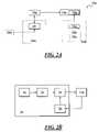
- FIG. 2Ais a schematic diagram of an exemplary atomizer
- FIG. 2Bis a schematic diagram of an exemplary control circuit
- FIG. 3Ais a perspective view of an atomizer with one actuator
- FIG. 3Bis a perspective view of an atomizer with two actuators
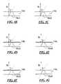
- FIG. 4A-4Gare magnified cross-sectional views of generally tapered perforations disposed within a substrate
- FIG. 5Ais a top plan view of an exemplary actuator plate arrangement
- FIG. 5Bis a side view of the actuator plate arrangement of FIG. 5A ;
- FIG. 5Cis a schematic diagram used to construct the actuator plate arrangement of FIGS. 5A and 5B ;
- FIG. 6Ais a table providing specifications for two exemplary plates A and B;
- FIG. 6Bis a schematic diagram of a control circuit for use with the first plate A of FIG. 6A ;
- FIG. 6Cis a schematic diagram of a control circuit for use with the second plate B of FIG. 6A ;
- FIG. 6Dis a table providing the spray properties of the two plates A and B of FIG. 6A .
- an exemplary high volume atomizer for use with air fresheners, deodorants, insecticides, repellents, cleaners, medicinal substance, aromatherapy substance, disinfectant, sanitizer, or other common consumer spray productsis referred to as reference number 10 . It is understood that the teachings of the disclosure can be used to construct atomizers and related dispensers above and beyond that specifically disclosed below. One of ordinary skill in the art will readily understand that the following are exemplary embodiments.
- an exemplary high volume piezoelectric atomizer 10 for common consumer spray productsmay include an actuator 12 and a substrate 14 to which the actuator 12 may be coupled.
- the actuator 12may be a piezoelectric ceramic actuator, or may be a piezoelectric crystal, a flextensional transducer, an oscillating magnetic couple, a high speed motor, a servo motor, or any other device that may be capable of vibrating the substrate 14 at relatively high frequencies and velocities.
- the substrate 14may employ an element such as a plate, a cantilever, a diving board, or the like, that may be elliptical, rectangular, cylindrical, or in any other shape or form.
- 1may further include a plurality of generally tapered perforations 16 , similar to those described in U.S. Pat. Nos. 5,164,740, 6,629,646 and 6,926,208 to Ivri (the disclosures of which are hereby incorporated by reference), which may be in contact with a liquid product supply 18 , such as a wick.
- a liquid product supply 18such as a wick.
- Wicksas described herein, have a plurality of non-capillary fibers and are adapted to the polarity and or non-polarity of a particular liquid product.
- Such wick compositionsserve to promote the ability to spray in any orientation and or direction, and to minimize inconsistencies caused by gravity. More specifically, gravity may significantly impede fluid flow if a wick is longer than a few millimeters and transports fluid against the force of gravity.
- the composition and properties of a wickmay be modified. Some important properties affecting the performance of a wick may include the pore size, pore volume and hydrophilicity. Of these properties, hydrophilicity has the greatest impact on the performance of a wick.
- the hydrophilicity of a wick compositionmay be one that is compatible with the polarity of a particular liquid product to be dispensed.
- liquid productsmay include aqueous mixtures of actives and other ingredients, for example, air fresheners, insecticides, repellents, cleaners, or the like.
- a typical hydrophilic wickfor example polyester, may be used for optimal compatibility and uninterrupted performance.
- cottonmay be too hydrophilic while polyethylene may be too hydrophobic.
- a hydrophobic wicksuch as polyethylene may provide better performance than cotton, nylon, polyester, or the like.
- the high volume piezoelectric atomizer 10may further include a liquid chamber 20 and a cap 22 for containing a liquid product.
- the wick 18may transport a liquid product from the liquid chamber 20 to the tapered perforations 16 to be atomized.
- the liquid chamber 20may be substantially sealed by the wick 18 and the cap 22 to prevent leaks and spills.
- the cap 22may include a gasket to further seal the liquid chamber 20 and to promote atomization of the liquid product in any direction and or orientation.
- the liquid chamber 20 and or cap 22may be removable to allow for refills.
- the atomizer 10may further include a trigger 24 and an electronics chamber 26 comprising a control circuit disposed therein.
- the electronics chamber 26may provide electrical communication between the control circuit, the piezoelectric actuator 12 and the trigger 24 .
- the control circuitmay be powered by at least one battery also disposed within the electronics chamber 26 .
- power to the control circuitmay be supplied by an external AC or DC source.
- a piezoelectric actuator 12may include a piezoelectric material that converts mechanical energy into electrical energy, and vice versa. More specifically, providing pulsed electrical current to a piezoelectric actuator 12 may mechanically vibrate the actuator 12 and its associated substrate 14 .
- a control circuit for providing such currentmay be provided in electrical communication with the piezoelectric actuator 12 via wires or other conductors. Upon actuation, the control circuit may vibrate the substrate 14 and its tapered perforations 16 against a liquid product supply or a wick 18 at velocities of 500 mm/s or more. Subsequently, the atomized liquid product may be dispensed from the perforations 16 to provide plumes of approximately 2 feet (610 mm) or more in length.
- an atomizer 10 amay include an actuator 12 a , a substrate 14 a with perforations 16 a coupled to the actuator 12 a , a supply of a liquid product 18 a in contact with the substrate 14 a , and a control circuit 28 . Additionally, the atomizer 10 a may further include a liquid chamber 20 a , a cap 22 a , a gasket 23 a , a trigger 24 a , and an electronics chamber 26 a , as indicated in phantom. Upon engaging the trigger 24 a , the control circuit 28 may begin vibrating the actuator 12 a . Vibrating the actuator 12 a may further vibrate the substrate 14 a and its perforations 16 a against the supply 18 a , and atomize a liquid product contained in the liquid chamber 20 a.
- a control circuit 28may include a power supply 30 , a voltage converter 32 , an oscillator 34 and a feedback circuit 36 .
- the power supply 30may provide the voltage converter 32 with a DC voltage from an internal or an external source.
- the converter 32may convert the voltage provided by the power supply 30 to a level suitable to drive the actuator 12 a .
- the oscillator 34may pulse the signal to vibrate the actuator 12 a .
- the feedback circuit 36may sample the vibration frequency and relay the information back to the oscillator 34 .
- the oscillator 34may adjust the frequency of the signal sent to the actuator 12 a.
- another exemplary high volume piezoelectric atomizer 10 bmay include a piezoelectric ceramic actuator 12 b and a substrate 14 b to which the actuator 12 b may be coupled.
- the actuator 12 bmay include a piezoelectric crystal, a flextensional transducer, an oscillating magnetic couple, a high speed motor, a servo motor, or any other device that may be capable of vibrating the substrate 14 b at relatively high frequencies.
- the substrate 14 bmay employ an element such as a plate, a cantilever, a diving board, or the like, that may be elliptical, rectangular, cylindrical, or of any other shape or form.
- 3Amay further include a plurality of generally tapered perforations 16 b which may be in contact with a supply of a liquid product, such as a wick 18 b .
- the wick 18 bmay transport a liquid product from a container, a reservoir, or the like, toward the tapered perforations 16 b to be atomized and dispensed in the general direction indicated by the exit arrow 30 .
- yet another exemplary high volume piezoelectric atomizer 10 b 1may include two piezoelectric ceramic actuators 12 b 1 , 12 b 1 ′ and a substrate 14 b 1 to which the actuators 12 b 1 , 12 b 1 ′ may be coupled.
- the actuators 12 b 1 , 12 b 1 ′may employ a piezoelectric crystal, a flextensional transducer, an oscillating magnetic couple, a high speed motor, a servo motor, or any other device that may be capable of vibrating the substrate 14 b at relatively high frequencies.
- the substrate 14 b 1may include a plate, a cantilever, a diving board, or the like, that may be elliptical, rectangular, cylindrical, or of any other shape or form.
- the substrate 14 b 1 of FIG. 3Bmay further include a plurality of generally tapered perforations 16 b 1 which may be in contact with a supply of a liquid product, such as a wick 18 b 1 .
- the wick 18 b 1may transport a liquid product from a container, a reservoir, or the like, toward the tapered perforations 16 b 1 to be atomized and dispensed in the general direction indicated by the exit arrow 31 .
- FIG. 4Aa detailed cross-sectional view of an exemplary tapered perforation 16 c of another substrate 14 c is shown with a wick 18 c , or a similar supply of a liquid product.
- the perforation 16 cmay be tapered with an angle ⁇ of approximately 20 to 30 degrees, and with an axis N normal to the substrate 14 c .
- the perforation 16 c 1may be tapered to form the shape of a bell with an average angle ⁇ .
- the perforations 16 c 2 , 16 c 3 of FIGS. 4C and 4Dare additional variations that may be tapered to only partially mimic a bell shape and form an average angle ⁇ with the normal axis N.
- each variation of FIGS. 4B-4Gmay form an average angle ⁇ of approximately 20 to 30 degrees with the axis N normal to the substrate 14 c.
- the tapered perforation 16 cmay be configured such that the larger opening of the perforation 16 c is in direct contact with the wick 18 c , or a similar liquid product supply. During atomization, a liquid product from the wick 18 c may enter the perforation 16 c through the larger opening. Subsequently, a plurality of droplets 32 may exit from the smaller opening to form a plume in the direction indicated by the exit arrow 34 .
- the arrangement 40may include an actuator 12 d and a plate substrate 14 d with a plurality of tapered perforations 16 d .
- the actuator 12 dmay further include wires 42 , or other similar conductors, which provide electrical communication to with a control circuit.
- the diagram of FIG. 5Cprovides an exemplary schematic that may be used to construct the particular arrangement 40 of FIGS. 5A and 5B .
- a piezoelectric ceramic 44may be employed to vibrate the arrangement 40 upon actuation.
- the piezoelectric ceramic 44may be substituted with a piezoelectric crystal, a flextensional material or any other means for vibrating the arrangement 40 at relatively high frequencies.
- wires 42may be soldered to silver electrodes 46 to provide the arrangement 40 with electric current from a control circuit.
- the silver electrodes 46may be coupled to the ceramic 44 using a conducting epoxy 48 , or the like.
- a thin layer of the silver 46may be coated onto the ceramic 44 using a silk screen, or a comparable process, and subsequently applying heat to affix the coat.
- electrodes 46 made from conducting metals other than silver, for example copper, gold, brass,may also be employed.
- the schematic of FIG. 5Cfurther includes a perforated nickel plate 14 d coupled to one of the electrodes 46 .
- the nickel plate 14 dmay be a plate of a different material, a cantilever, a diving board, or any other perforated substrate that may be elliptical, rectangular, cylindrical, or in any other shape or form.
- the plate 14 dmay further include a plurality of perforations that are tapered at specific angles for optimal pumping efficiency.
- the perforationsmay employ a bell shaped taper which forms average taper angles of approximately 20 to 30 degrees with an axis normal to the plate 14 d.
- the size of the droplets released by an atomizermay include the size of the perforations in a substrate, or a plate, and the velocity at which the plate vibrates. Moreover, at a constant plate velocity, the droplet size may increase with increasing perforation size, and at a constant perforation size, the droplet size may increase with increasing plate velocity.
- testsprovided unexpected results with respect to the particle size of droplets dispensed. It has been determined that a plate with larger perforations may produce a spray with significantly smaller droplets or particles. More specifically, at constant drive voltage and resonant frequency, higher plate velocities in combination with smaller perforations produced larger particles than lower plate velocities and larger perforations.
- the specifications of two different substrates, or plates, A, B that resonate at the same frequencyare provided solely to illustrate the aforementioned findings.
- the plates A, Bwere constructed with different dimensions and perforation formats. Specifically, the first plate A has smaller dimensions and smaller perforations than those of the second plate B.
- Such variations in weight, shape, and other similar properties of the platemay cause an arrangement to vibrate at different frequencies and may require separate control circuits. Accordingly, separate control circuits were constructed to vibrate the plates A, B and to compensate for these variations. Smaller perturbations to any part of the arrangement, for example scratches, foreign objects, forces applied by a wick, components of a liquid product, or the like, may also affect performance. However, these smaller perturbations may be overcome by providing the control circuit with feedback means so as to self resonate at specific frequencies.
- the control circuit 128 amay include a switch 129 a , a battery 130 a , a boost converter 132 a , an oscillator 134 a and a feedback circuit 136 a .
- the battery 130 asupplies a DC voltage to the boost converter 132 a .
- the boost converter 132 aconverts the input voltage to a higher DC voltage required to drive the actuator 112 a .
- the oscillator 134 a and the feedback circuit 136 adetermine the optimum operating frequency, or series resonant frequency, by sampling current passing through the actuator 112 a .
- the control circuit 128 aminimizes impedance and allows the arrangement A to be operated at a relatively low voltage. Accordingly, the control circuit 128 a is able to consistently drive power to the load 112 a and overcome small perturbations.
- the control circuit 128 bmay include a switch 129 b , a DC power supply 130 b , an impedance transformation network 132 b , an oscillator 134 b and a feedback circuit 136 b .
- the power supply 130 bfeeds DC voltage to the impedance transformation network 132 b , which converts the incoming voltage to a higher AC voltage required to drive the actuator 112 b .
- the oscillator 134 b and the feedback circuit 136 bwork together to vibrate the plate arrangement B more efficiently.
- the oscillator 134 b and the feedback circuit 136 bdetermine the series resonant frequency by sampling current passing through the actuator 112 b .
- the second control circuit 128 bis also able to consistently drive power to the load and overcome small perturbations.
- the resulting properties of sprays from both arrangements A, Bare provided.
- Data corresponding to the particle size of the droplets from each spraywere collected on a MalvernTM Mastersizer S analyzer. At least five measurements were taken at a distance of 8 inches from each plate A, B, and averaged. The plume distance was estimated subjectively by observers over multiple sprays, and averaged. For this particular experiment, each spray was discharged vertically and the corresponding plume distance was estimated to be the reach of the majority of the spray. Alternative means for measuring plume distance may also be employed. The perforation or plate velocity was measured on a Polytec® PSV-400 Scanning Laser Dopler Vibrometer. Furthermore, the discharge rate was determined through the change in weight of sprays over an interval of 10 seconds. The results presented are averages of three trials.
- FIG. 6Demphasize the significance of plate velocity and its ability to vary the size of dispensed droplets. Moreover, despite its larger perforations, droplets produced by the second plate B were significantly smaller than those produced by the first plate A. This is due to the difference in plate velocities between the two arrangements A, B. More specifically, plate A moved much faster than plate B. Although both arrangements A, B were driven at the same resonant frequency, plate A moved faster because of its smaller structure.
- the performance of an atomizermay be measured by examining the properties of its spray. More relevant spray properties may include the size of the droplets, plume length and the rate of discharge. A simplified approach to measuring atomizer performance may combine these traits into one index, for example, a Valpey factor.
- the Valpey factorsummarizes atomizer performance, by combining the droplet size, plume length and the discharge rate of an atomizer into one index.
- the present disclosureprovides a high volume atomizer with features that improves efficiency and performance.
- a liquid productinto smaller droplets, longer plumes and greater discharge rates.
- an atomizer constructed in accordance with the teachings of the disclosureis capable of providing plume lengths of approximately 2 ft (610 mm) or more and discharge rates of approximately 0.20 g/s or more.
- the performance of the present disclosuremay be summarized to exhibit a Valpey factor of 51.0 or more. Atomizers currently existing in the art exhibit only a fraction of this value.
- the present disclosureis capable of atomizing in any orientation without leaking and without significantly affecting performance.
- the atomizerincludes a liquid chamber with a cap and a gasket, and a novel plate arrangement that is in direct contact with a supply of a liquid product to substantially seal in a liquid product.
- the supply of a liquid productis not provided by capillary action but by using the polarity or non-polarity of a liquid product.
- the technologyallows the device to atomize consistently while it is upright, upside down, sideways, or in any other orientation. This is a significant improvement over atomizers currently existing in the art which may leak, spill or not work at all in such orientations. While a few atomizers may be able to spray in these positions without leaking, their performance is inconsistent and gradually decreases in quality.
Landscapes
- Special Spraying Apparatus (AREA)
Abstract
Description
Vf=100rd+0.1lp−xd
where rdis the discharge rate in g/s, lpis the observed plume length in mm, and xdis the droplet size in microns. The Valpey factor summarizes atomizer performance, by combining the droplet size, plume length and the discharge rate of an atomizer into one index.
Claims (27)
Priority Applications (2)
| Application Number | Priority Date | Filing Date | Title |
|---|---|---|---|
| US12/112,714US7891580B2 (en) | 2008-04-30 | 2008-04-30 | High volume atomizer for common consumer spray products |
| CA2662468ACA2662468C (en) | 2008-04-30 | 2009-04-14 | High volume atomizer for common consumer spray products |
Applications Claiming Priority (1)
| Application Number | Priority Date | Filing Date | Title |
|---|---|---|---|
| US12/112,714US7891580B2 (en) | 2008-04-30 | 2008-04-30 | High volume atomizer for common consumer spray products |
Publications (2)
| Publication Number | Publication Date |
|---|---|
| US20090272818A1 US20090272818A1 (en) | 2009-11-05 |
| US7891580B2true US7891580B2 (en) | 2011-02-22 |
Family
ID=41255963
Family Applications (1)
| Application Number | Title | Priority Date | Filing Date |
|---|---|---|---|
| US12/112,714Expired - Fee RelatedUS7891580B2 (en) | 2008-04-30 | 2008-04-30 | High volume atomizer for common consumer spray products |
Country Status (2)
| Country | Link |
|---|---|
| US (1) | US7891580B2 (en) |
| CA (1) | CA2662468C (en) |
Cited By (12)
| Publication number | Priority date | Publication date | Assignee | Title |
|---|---|---|---|---|
| US20120095279A1 (en)* | 2002-08-23 | 2012-04-19 | Sheiman Ultrasonic Research Foundation Pty Ltd | Nebulizing and drug delivery device |
| US20120187209A1 (en)* | 2009-05-11 | 2012-07-26 | Monash University | Microfluidic apparatus for the atomisation of a liquid |
| US20120285446A1 (en)* | 2010-01-11 | 2012-11-15 | Martinus Bernardus Van Der Mark | Magnetic coupling for aerosol generating apparatus |
| US20120291776A1 (en)* | 2010-01-11 | 2012-11-22 | Koninklijke Philips Electronics, N.V. | Magnetic coupling for aerosol generating apparatus |
| CN104582647A (en)* | 2011-12-12 | 2015-04-29 | 艾诺维亚股份有限公司 | Ejector mechanism, ejector device, and methods of use |
| US20150165466A1 (en)* | 2013-12-18 | 2015-06-18 | Agilent Technologies, Inc. | Ultrasonic nebulizer with controlled mist output |
| US20160107186A1 (en)* | 2014-10-16 | 2016-04-21 | Hsuan-Yu Chao | Essential Oil Diffuser |
| CN104582647B (en)* | 2011-12-12 | 2016-11-30 | 艾诺维亚股份有限公司 | Injection mechanism, injection device and method of use |
| US10946407B2 (en)* | 2016-04-07 | 2021-03-16 | David B. Go | Apparatus and method for atomization of fluid |
| US11398306B2 (en) | 2010-07-15 | 2022-07-26 | Eyenovia, Inc. | Ophthalmic drug delivery |
| US11938056B2 (en) | 2017-06-10 | 2024-03-26 | Eyenovia, Inc. | Methods and devices for handling a fluid and delivering the fluid to the eye |
| US12161585B2 (en) | 2019-12-11 | 2024-12-10 | Eyenovia, Inc. | Systems and devices for delivering fluids to the eye and methods of use |
Families Citing this family (23)
| Publication number | Priority date | Publication date | Assignee | Title |
|---|---|---|---|---|
| HUE058021T2 (en)* | 2009-10-13 | 2022-06-28 | Philip Morris Products Sa | Aerosol generator |
| WO2011061480A1 (en) | 2009-11-18 | 2011-05-26 | Reckitt Benckiser Llc | Surface treatment device and method |
| WO2011061478A1 (en) | 2009-11-18 | 2011-05-26 | Reckitt Benckiser Llc | Lavatory treatment device and method |
| WO2012009706A1 (en)* | 2010-07-15 | 2012-01-19 | Corinthian Ophthalmic, Inc. | Drop generating device |
| AU2013245946A1 (en) | 2012-04-10 | 2014-11-27 | Eyenovia, Inc. | Spray ejector mechanisms and devices providing charge isolation and controllable droplet charge, and low dosage volume opthalmic administration |
| CN109011046B (en) | 2012-04-20 | 2021-10-01 | 艾诺维亚股份有限公司 | Device for delivering a fluid to a target |
| CN104602653B (en) | 2012-05-14 | 2018-02-16 | 艾诺维亚股份有限公司 | Laminar flow drop generator device and application method |
| EA201492094A1 (en) | 2012-05-15 | 2015-04-30 | Айновиа, Инк. | EJECTOR DEVICES, METHODS, PATTERNS AND SCHEMES FOR THEM |
| GB201603823D0 (en) | 2016-03-04 | 2016-04-20 | Univ College Cork Nat Univ Ie | A micro-fabricated mesh device and method of making same |
| WO2017192774A1 (en) | 2016-05-03 | 2017-11-09 | Pneuma Respiratory, Inc. | Methods for the systemic delivery of therapeutic agents to the pulmonary system using a droplet delivery device |
| WO2017192782A1 (en) | 2016-05-03 | 2017-11-09 | Pneuma Respiratory, Inc. | Systems and methods comprising a droplet delivery device and a breathing assist device for therapeutic treatment |
| CA3022916C (en) | 2016-05-03 | 2020-03-10 | Pneuma Respiratory, Inc. | Droplet delivery device for delivery of fluids to the pulmonary system and methods of use |
| US11285283B2 (en) | 2016-05-03 | 2022-03-29 | Pneuma Respiratory, Inc. | Methods for generating and delivering droplets to the pulmonary system using a droplet delivery device |
| US11285284B2 (en) | 2016-05-03 | 2022-03-29 | Pneuma Respiratory, Inc. | Methods for treatment of pulmonary lung diseases with improved therapeutic efficacy and improved dose efficiency |
| CN110799231B (en) | 2017-05-19 | 2022-08-02 | 精呼吸股份有限公司 | Dry powder conveying device and using method thereof |
| CN111526914A (en) | 2017-10-04 | 2020-08-11 | 精呼吸股份有限公司 | Electronic respiration actuated linear liquid drop conveying device and using method thereof |
| CA3079189A1 (en) | 2017-10-17 | 2019-04-25 | Pneuma Respiratory, Inc. | Nasal drug delivery apparatus and methods of use |
| IT201700116889A1 (en)* | 2017-10-18 | 2018-01-18 | Italian Lifestyle S R L | NEBULIZER DEVICE OF A FLUID FOR THE CARE AND / OR PROTECTION OF SKIN, IN PARTICULAR OF ACTIVE INGREDIENTS. |
| JP2021502178A (en) | 2017-11-08 | 2021-01-28 | ニューマ・リスパイラトリー・インコーポレイテッド | In-line droplet delivery device with a small volume ampoule and electrically actuated by breathing and how to use |
| CN115697264A (en) | 2020-05-13 | 2023-02-03 | 二十二十治疗有限责任公司 | Ocular drug applicator with light assisted alignment and targeting |
| WO2022200151A1 (en)* | 2021-03-22 | 2022-09-29 | Stamford Devices Limited | An aerosol generator core |
| KR20240037245A (en) | 2021-06-22 | 2024-03-21 | 뉴마 레스퍼러토리 인코포레이티드 | Droplet delivery device by push ejection |
| KR20250038748A (en) | 2022-07-18 | 2025-03-19 | 뉴마 레스퍼러토리 인코포레이티드 | Small step size and high resolution aerosol generation system and method |
Citations (27)
| Publication number | Priority date | Publication date | Assignee | Title |
|---|---|---|---|---|
| US4119096A (en) | 1975-08-25 | 1978-10-10 | Siemens Aktiengesellschaft | Medical inhalation device for the treatment of diseases of the respiratory tract |
| US4753579A (en) | 1986-01-22 | 1988-06-28 | Piezo Electric Products, Inc. | Ultrasonic resonant device |
| US4877989A (en) | 1986-08-11 | 1989-10-31 | Siemens Aktiengesellschaft | Ultrasonic pocket atomizer |
| US5511726A (en) | 1988-09-23 | 1996-04-30 | Battelle Memorial Institute | Nebulizer device |
| US5518179A (en)* | 1991-12-04 | 1996-05-21 | The Technology Partnership Limited | Fluid droplets production apparatus and method |
| US5685485A (en) | 1994-03-22 | 1997-11-11 | Siemens Aktiengesellschaft | Apparatus for apportioning and atomizing fluids |
| US5823428A (en)* | 1994-06-23 | 1998-10-20 | The Technology Partnership Plc | Liquid spray apparatus and method |
| US6293474B1 (en) | 1999-03-08 | 2001-09-25 | S. C. Johnson & Son, Inc. | Delivery system for dispensing volatiles |
| US6296196B1 (en)* | 1999-03-05 | 2001-10-02 | S. C. Johnson & Son, Inc. | Control system for atomizing liquids with a piezoelectric vibrator |
| US6339897B1 (en) | 1997-07-08 | 2002-01-22 | Microfab Technologies, Inc. | Method and apparatus for dispensing airborne materials for controlling pests |
| US6378780B1 (en) | 1999-02-09 | 2002-04-30 | S. C. Johnson & Son, Inc. | Delivery system for dispensing volatiles |
| US6382522B2 (en) | 1999-03-08 | 2002-05-07 | S. C. Johnson & Son, Inc. | Attachment method for piezoelectric elements |
| US6450419B1 (en) | 2000-10-27 | 2002-09-17 | S.C. Johnson & Son, Inc. | Self contained liquid atomizer assembly |
| US6450417B1 (en) | 1995-12-21 | 2002-09-17 | Kimberly-Clark Worldwide Inc. | Ultrasonic liquid fuel injection apparatus and method |
| US6540153B1 (en)* | 1991-04-24 | 2003-04-01 | Aerogen, Inc. | Methods and apparatus for dispensing liquids as an atomized spray |
| US6706988B1 (en)* | 2002-11-08 | 2004-03-16 | S. C. Johnson & Son, Inc. | Switch actuating mechanism and electrically controlled device using same |
| US6843430B2 (en) | 2002-05-24 | 2005-01-18 | S. C. Johnson & Son, Inc. | Low leakage liquid atomization device |
| US20050023368A1 (en) | 2003-01-24 | 2005-02-03 | S.C. Johnson & Son, Inc. | Method of designing improved spray dispenser assemblies |
| US6854662B2 (en)* | 2002-06-25 | 2005-02-15 | Kai Chih Industrial Co., Ltd. | Nebulizer assembly |
| US6857580B2 (en)* | 2001-12-03 | 2005-02-22 | S.C. Johnson & Son, Inc. | Plug-in type liquid atomizer |
| US6969008B2 (en) | 2003-01-29 | 2005-11-29 | S. C. Johnson & Son, Inc. | Point of purchase fragrance sampling |
| US20050271371A1 (en) | 2004-06-07 | 2005-12-08 | Wefler Mark E | Automobile air freshening system |
| US20060011737A1 (en)* | 2002-02-11 | 2006-01-19 | Sara Lee/De B.V. | Liquid spray head, apparatus comprising a liquid spray-head and container therefore |
| US20060026817A1 (en) | 2004-07-23 | 2006-02-09 | Valpey Richard S Iii | Method for designing aerosol spray dispensers |
| US7017829B2 (en) | 2003-04-14 | 2006-03-28 | S. C. Johnson & Son, Inc. | Atomizer wicking system |
| US7108197B2 (en)* | 1991-04-24 | 2006-09-19 | Aerogen, Inc. | Droplet ejector with oscillating tapered aperture |
| US7281811B2 (en) | 2005-03-31 | 2007-10-16 | S. C. Johnson & Son, Inc. | Multi-clarity lenses |
Family Cites Families (1)
| Publication number | Priority date | Publication date | Assignee | Title |
|---|---|---|---|---|
| EP1432526B1 (en)* | 2002-01-22 | 2011-12-07 | Nordson Corporation | Method and apparatus for detecting a liquid spray pattern |
- 2008
- 2008-04-30USUS12/112,714patent/US7891580B2/ennot_activeExpired - Fee Related
- 2009
- 2009-04-14CACA2662468Apatent/CA2662468C/ennot_activeExpired - Fee Related
Patent Citations (29)
| Publication number | Priority date | Publication date | Assignee | Title |
|---|---|---|---|---|
| US4119096A (en) | 1975-08-25 | 1978-10-10 | Siemens Aktiengesellschaft | Medical inhalation device for the treatment of diseases of the respiratory tract |
| US4753579A (en) | 1986-01-22 | 1988-06-28 | Piezo Electric Products, Inc. | Ultrasonic resonant device |
| US4877989A (en) | 1986-08-11 | 1989-10-31 | Siemens Aktiengesellschaft | Ultrasonic pocket atomizer |
| US5511726A (en) | 1988-09-23 | 1996-04-30 | Battelle Memorial Institute | Nebulizer device |
| US7108197B2 (en)* | 1991-04-24 | 2006-09-19 | Aerogen, Inc. | Droplet ejector with oscillating tapered aperture |
| US6921020B2 (en)* | 1991-04-24 | 2005-07-26 | Aerogen, Inc. | Method and apparatus for dispensing liquids as an atomized spray |
| US6540153B1 (en)* | 1991-04-24 | 2003-04-01 | Aerogen, Inc. | Methods and apparatus for dispensing liquids as an atomized spray |
| US5518179A (en)* | 1991-12-04 | 1996-05-21 | The Technology Partnership Limited | Fluid droplets production apparatus and method |
| US5685485A (en) | 1994-03-22 | 1997-11-11 | Siemens Aktiengesellschaft | Apparatus for apportioning and atomizing fluids |
| US5823428A (en)* | 1994-06-23 | 1998-10-20 | The Technology Partnership Plc | Liquid spray apparatus and method |
| US6450417B1 (en) | 1995-12-21 | 2002-09-17 | Kimberly-Clark Worldwide Inc. | Ultrasonic liquid fuel injection apparatus and method |
| US6339897B1 (en) | 1997-07-08 | 2002-01-22 | Microfab Technologies, Inc. | Method and apparatus for dispensing airborne materials for controlling pests |
| US6378780B1 (en) | 1999-02-09 | 2002-04-30 | S. C. Johnson & Son, Inc. | Delivery system for dispensing volatiles |
| US6296196B1 (en)* | 1999-03-05 | 2001-10-02 | S. C. Johnson & Son, Inc. | Control system for atomizing liquids with a piezoelectric vibrator |
| US6439474B2 (en) | 1999-03-05 | 2002-08-27 | S. C. Johnson & Son, Inc. | Control system for atomizing liquids with a piezoelectric vibrator |
| US6293474B1 (en) | 1999-03-08 | 2001-09-25 | S. C. Johnson & Son, Inc. | Delivery system for dispensing volatiles |
| US6382522B2 (en) | 1999-03-08 | 2002-05-07 | S. C. Johnson & Son, Inc. | Attachment method for piezoelectric elements |
| US6450419B1 (en) | 2000-10-27 | 2002-09-17 | S.C. Johnson & Son, Inc. | Self contained liquid atomizer assembly |
| US6857580B2 (en)* | 2001-12-03 | 2005-02-22 | S.C. Johnson & Son, Inc. | Plug-in type liquid atomizer |
| US20060011737A1 (en)* | 2002-02-11 | 2006-01-19 | Sara Lee/De B.V. | Liquid spray head, apparatus comprising a liquid spray-head and container therefore |
| US6843430B2 (en) | 2002-05-24 | 2005-01-18 | S. C. Johnson & Son, Inc. | Low leakage liquid atomization device |
| US6854662B2 (en)* | 2002-06-25 | 2005-02-15 | Kai Chih Industrial Co., Ltd. | Nebulizer assembly |
| US6706988B1 (en)* | 2002-11-08 | 2004-03-16 | S. C. Johnson & Son, Inc. | Switch actuating mechanism and electrically controlled device using same |
| US20050023368A1 (en) | 2003-01-24 | 2005-02-03 | S.C. Johnson & Son, Inc. | Method of designing improved spray dispenser assemblies |
| US6969008B2 (en) | 2003-01-29 | 2005-11-29 | S. C. Johnson & Son, Inc. | Point of purchase fragrance sampling |
| US7017829B2 (en) | 2003-04-14 | 2006-03-28 | S. C. Johnson & Son, Inc. | Atomizer wicking system |
| US20050271371A1 (en) | 2004-06-07 | 2005-12-08 | Wefler Mark E | Automobile air freshening system |
| US20060026817A1 (en) | 2004-07-23 | 2006-02-09 | Valpey Richard S Iii | Method for designing aerosol spray dispensers |
| US7281811B2 (en) | 2005-03-31 | 2007-10-16 | S. C. Johnson & Son, Inc. | Multi-clarity lenses |
Cited By (20)
| Publication number | Priority date | Publication date | Assignee | Title |
|---|---|---|---|---|
| US8671935B2 (en)* | 2002-08-23 | 2014-03-18 | Sheiman Ultrasonic Research Foundation Pty Ltd. | Synergistic drug delivery device |
| US20120095279A1 (en)* | 2002-08-23 | 2012-04-19 | Sheiman Ultrasonic Research Foundation Pty Ltd | Nebulizing and drug delivery device |
| US20120187209A1 (en)* | 2009-05-11 | 2012-07-26 | Monash University | Microfluidic apparatus for the atomisation of a liquid |
| US8991722B2 (en)* | 2009-05-11 | 2015-03-31 | Monash University | Microfluidic apparatus for the atomisation of a liquid |
| US9050424B2 (en)* | 2010-01-11 | 2015-06-09 | Koninklijke Philips N.V. | Magnetic coupling for aerosol generating apparatus |
| US20120285446A1 (en)* | 2010-01-11 | 2012-11-15 | Martinus Bernardus Van Der Mark | Magnetic coupling for aerosol generating apparatus |
| US20120291776A1 (en)* | 2010-01-11 | 2012-11-22 | Koninklijke Philips Electronics, N.V. | Magnetic coupling for aerosol generating apparatus |
| US9050425B2 (en)* | 2010-01-11 | 2015-06-09 | Koninklijke Philips N.V. | Magnetic coupling for aerosol generating apparatus |
| US11839487B2 (en) | 2010-07-15 | 2023-12-12 | Eyenovia, Inc. | Ophthalmic drug delivery |
| US11398306B2 (en) | 2010-07-15 | 2022-07-26 | Eyenovia, Inc. | Ophthalmic drug delivery |
| US12268517B2 (en) | 2010-07-15 | 2025-04-08 | Eyenovia, Inc. | Drop generating device |
| CN104582647B (en)* | 2011-12-12 | 2016-11-30 | 艾诺维亚股份有限公司 | Injection mechanism, injection device and method of use |
| CN104582647A (en)* | 2011-12-12 | 2015-04-29 | 艾诺维亚股份有限公司 | Ejector mechanism, ejector device, and methods of use |
| US20150165466A1 (en)* | 2013-12-18 | 2015-06-18 | Agilent Technologies, Inc. | Ultrasonic nebulizer with controlled mist output |
| US20160107186A1 (en)* | 2014-10-16 | 2016-04-21 | Hsuan-Yu Chao | Essential Oil Diffuser |
| US9623137B2 (en)* | 2014-10-16 | 2017-04-18 | Hsuan-Yu Chao | Essential oil diffuser |
| US10946407B2 (en)* | 2016-04-07 | 2021-03-16 | David B. Go | Apparatus and method for atomization of fluid |
| US11938056B2 (en) | 2017-06-10 | 2024-03-26 | Eyenovia, Inc. | Methods and devices for handling a fluid and delivering the fluid to the eye |
| US12213912B2 (en) | 2017-06-10 | 2025-02-04 | Eyenovia, Inc. | Methods and devices for handling a fluid and delivering the fluid to the eye |
| US12161585B2 (en) | 2019-12-11 | 2024-12-10 | Eyenovia, Inc. | Systems and devices for delivering fluids to the eye and methods of use |
Also Published As
| Publication number | Publication date |
|---|---|
| CA2662468C (en) | 2013-02-19 |
| US20090272818A1 (en) | 2009-11-05 |
| CA2662468A1 (en) | 2009-10-30 |
Similar Documents
| Publication | Publication Date | Title |
|---|---|---|
| US7891580B2 (en) | High volume atomizer for common consumer spray products | |
| CA2362111C (en) | Piezoelectric spraying system for dispensing volatiles | |
| EP1471950B1 (en) | Method and apparatus for evaporating multi-component liquids | |
| CN1211166C (en) | Oscillating atomizer and refill container for the oscillating atomizer | |
| EP1305119B1 (en) | Method and apparatus for dispensing liquids in aerosolized form with minimum spillage | |
| CN1069231C (en) | Electrostatic sprayer | |
| US20080099572A1 (en) | Delivery system for dispensing volatiles | |
| AU2001280991A1 (en) | Method and apparatus for dispensing liquids in aerosolized form with minimum spillage | |
| CN1347349A (en) | Improved attachment method for piezoelectric elements | |
| JP2008504932A (en) | Improved wick to control liquid overflow and release rate | |
| EP1430958A2 (en) | Piezoelectric spraying system for dispensing volatiles | |
| EP2100671B1 (en) | Method and device for nebulising high-viscosity liquids with minimal fallback | |
| WO2021014129A1 (en) | A dispenser | |
| HK1059908B (en) | Method and apparatus for dispensing liquids in aerosolized form with minimum spillage | |
| HK1044306B (en) | Piezoelectric spraying method for dispensing volatiles and system thereof | |
| MXPA01008049A (en) | Piezoelectric spraying system for dispensing volatiles |
Legal Events
| Date | Code | Title | Description |
|---|---|---|---|
| AS | Assignment | Owner name:BIT 7, INC., WISCONSIN Free format text:ASSIGNMENT OF ASSIGNORS INTEREST;ASSIGNOR:BLANDINO, THOMAS P.;REEL/FRAME:025503/0280 Effective date:20080428 Owner name:S.C. JOHNSON & SON, INC., WISCONSIN Free format text:ASSIGNMENT OF ASSIGNORS INTEREST;ASSIGNORS:VALPEY, RICHARD S., III;GU, WENLU;HELF, THOMAS A.;SIGNING DATES FROM 20080423 TO 20080429;REEL/FRAME:025503/0257 Owner name:S.C. JOHNSON & SON, INC., WISCONSIN Free format text:ASSIGNMENT OF ASSIGNORS INTEREST;ASSIGNOR:BIT 7, INC.;REEL/FRAME:025503/0316 Effective date:20080428 | |
| STCF | Information on status: patent grant | Free format text:PATENTED CASE | |
| CC | Certificate of correction | ||
| FPAY | Fee payment | Year of fee payment:4 | |
| FEPP | Fee payment procedure | Free format text:MAINTENANCE FEE REMINDER MAILED (ORIGINAL EVENT CODE: REM.); ENTITY STATUS OF PATENT OWNER: LARGE ENTITY | |
| LAPS | Lapse for failure to pay maintenance fees | Free format text:PATENT EXPIRED FOR FAILURE TO PAY MAINTENANCE FEES (ORIGINAL EVENT CODE: EXP.); ENTITY STATUS OF PATENT OWNER: LARGE ENTITY | |
| STCH | Information on status: patent discontinuation | Free format text:PATENT EXPIRED DUE TO NONPAYMENT OF MAINTENANCE FEES UNDER 37 CFR 1.362 | |
| FP | Lapsed due to failure to pay maintenance fee | Effective date:20190222 |