US7891274B2 - High strength fastener system - Google Patents
High strength fastener systemDownload PDFInfo
- Publication number
- US7891274B2 US7891274B2US12/231,459US23145908AUS7891274B2US 7891274 B2US7891274 B2US 7891274B2US 23145908 AUS23145908 AUS 23145908AUS 7891274 B2US7891274 B2US 7891274B2
- Authority
- US
- United States
- Prior art keywords
- driver
- projections
- radius
- fastener
- central core
- Prior art date
- Legal status (The legal status is an assumption and is not a legal conclusion. Google has not performed a legal analysis and makes no representation as to the accuracy of the status listed.)
- Active - Reinstated, expires
Links
- 238000009434installationMethods0.000claimsabstractdescription27
- 230000013011matingEffects0.000claimsdescription23
- 230000007704transitionEffects0.000claimsdescription17
- 238000000034methodMethods0.000claimsdescription10
- 238000009826distributionMethods0.000description4
- 230000006735deficitEffects0.000description3
- 238000004904shorteningMethods0.000description3
- 230000006872improvementEffects0.000description2
- 238000012986modificationMethods0.000description2
- 230000004048modificationEffects0.000description2
- 230000009467reductionEffects0.000description2
- 238000012360testing methodMethods0.000description2
- 230000003466anti-cipated effectEffects0.000description1
- 230000008901benefitEffects0.000description1
- 230000005540biological transmissionEffects0.000description1
- 238000010276constructionMethods0.000description1
- 238000013461designMethods0.000description1
- 238000011161developmentMethods0.000description1
- 230000018109developmental processEffects0.000description1
- 238000004519manufacturing processMethods0.000description1
- 230000007480spreadingEffects0.000description1
- 238000003892spreadingMethods0.000description1
Images


Classifications
- B—PERFORMING OPERATIONS; TRANSPORTING
- B25—HAND TOOLS; PORTABLE POWER-DRIVEN TOOLS; MANIPULATORS
- B25B—TOOLS OR BENCH DEVICES NOT OTHERWISE PROVIDED FOR, FOR FASTENING, CONNECTING, DISENGAGING OR HOLDING
- B25B15/00—Screwdrivers
- B25B15/001—Screwdrivers characterised by material or shape of the tool bit
- B25B15/004—Screwdrivers characterised by material or shape of the tool bit characterised by cross-section
- B25B15/005—Screwdrivers characterised by material or shape of the tool bit characterised by cross-section with cross- or star-shaped cross-section
- F—MECHANICAL ENGINEERING; LIGHTING; HEATING; WEAPONS; BLASTING
- F16—ENGINEERING ELEMENTS AND UNITS; GENERAL MEASURES FOR PRODUCING AND MAINTAINING EFFECTIVE FUNCTIONING OF MACHINES OR INSTALLATIONS; THERMAL INSULATION IN GENERAL
- F16B—DEVICES FOR FASTENING OR SECURING CONSTRUCTIONAL ELEMENTS OR MACHINE PARTS TOGETHER, e.g. NAILS, BOLTS, CIRCLIPS, CLAMPS, CLIPS OR WEDGES; JOINTS OR JOINTING
- F16B23/00—Specially shaped nuts or heads of bolts or screws for rotations by a tool
- F16B23/0007—Specially shaped nuts or heads of bolts or screws for rotations by a tool characterised by the shape of the recess or the protrusion engaging the tool
- F16B23/0023—Specially shaped nuts or heads of bolts or screws for rotations by a tool characterised by the shape of the recess or the protrusion engaging the tool substantially cross-shaped
- Y—GENERAL TAGGING OF NEW TECHNOLOGICAL DEVELOPMENTS; GENERAL TAGGING OF CROSS-SECTIONAL TECHNOLOGIES SPANNING OVER SEVERAL SECTIONS OF THE IPC; TECHNICAL SUBJECTS COVERED BY FORMER USPC CROSS-REFERENCE ART COLLECTIONS [XRACs] AND DIGESTS
- Y10—TECHNICAL SUBJECTS COVERED BY FORMER USPC
- Y10T—TECHNICAL SUBJECTS COVERED BY FORMER US CLASSIFICATION
- Y10T29/00—Metal working
- Y10T29/49—Method of mechanical manufacture
Definitions
- the disclosed embodimentsgenerally relate to fastener systems including fastener, driver, method of manufacture and related tooling.
- fastenershaving spiral drive and removal surfaces that enable high seating torques to be applied.
- Fasteners having driver engageable surfaces that are, at least in part, defined by spiral segmentshave been used with good results.
- Fastener systems of this typeare described in U.S. Pat. Nos. 5,957,645, 6,234,914, and 6,367,358 issued to Stacy and commonly owned with this application. The disclosures of these patents are incorporated herein by reference.
- the drive surfaces of the Stacy fastener systemare constructed to maximize torque transmission, during installation and removal, while spreading the driving load over a broad driver/fastener interface.
- the thrust of these teachingsis to enlarge the area of the drive surfaces.
- the problem to which this application is directedis to construct a drive fastener interface that increases the strength of the driver without significantly effecting the load distribution characteristics of the spiral interface surfaces.
- a fastener systemis constructed having driver/fastener interface surfaces configured in the general shape of a segment of a spiral on both of the installation and removal surfaces.
- the recess and driver cross sectional shapesare constructed with an increased core diameter over the prior art spiral fastener system. This is accompanied by a shortening of the radial extension of the wing of both recess and driver cross sections beyond the core diameter.
- the wing cross section of the driver/recessis further modified by moving the installation and removal surfaces in a parallel manner to form a truncated wing shape with a blunt tip.
- the blunt tipis constructed to conform to a circle, concentric with the core, with a diameter larger than the core diameter.
- the drive surfacesare constructed to intersect the core diameter in a transitional surface between the wings that has a concave form conforming to the core diameter.
- the wing portion of the driver/recess cross sectionis constructed so that the ratio of the core radius to wing tip radius is greater than 0.55 and the transition surface between the wings is a concave segment of the core circumference.
- the ratio of the height of the wing cross section to its widthis constructed to be approximately equal to or less than 0.5.
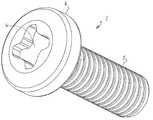
- FIG. 1is a perspective view of a fastener having spirally configured drive surfaces of the prior art
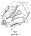
- FIG. 2is a perspective view of a driver having spirally configured drive surfaces of the prior art
- FIG. 3is a perspective view of an embodiment of a spirally configured fastener illustrating the subject matter of this application;
- FIG. 4is a perspective view of a spirally configured driver illustrating the subject matter of this application.
- FIG. 5is a chart showing the relative increase in torque capability of the fastener system of this application compared to prior art spirally configured fastener systems.
- FIG. 6is a cross sectional view of an embodiment of a fastener driver according to the subject matter of this application with a cross section of the prior art driver superimposed shown with dashed outline.
- FIGS. 3 and 4 of this applicationillustrate, as an example, a fastener and driver bit of a fastener system having features of an embodiment of this application.
- a fastener system 1is shown in FIGS. 3 and 4 and consists of fastener 2 and driver bit 3 .
- Fastener 2is constructed having a head 4 and a threaded shank 5 .
- a spirally configured recess 6is formed in head 4 .
- Driver bit 3is constructed having spirally configured drive surfaces that mate with the corresponding surfaces of fastener recess 6 .
- driver bit 3utilizes a generally cruciform shape having wings 7 a,b,c , and d .
- the overall shapes and number of wingsmay be varied from the example illustrated.
- Each of the wingshave a substantially similar shape with an installation surface 8 , a tip portion 11 and a removal surface 9 that define the wings 7 .
- a transition surface 10extends between the installation and removal surfaces of adjacent wings, such as wings 7 a and 7 b as shown in FIG. 4 .
- the overall shape of the recess 6 and driver bit 3is similar, except the bit 3 is smaller to provide a clearance between driver and fastener to promote engagement and removal of the driver bit 3 from the recess 6 .
- the driver bit installation and removal wallsare slightly different from the corresponding recess walls so rotation of the bit will provide a full face to face engagement on both the removal and installation wall.
- the driver/fastener interface surfacesare configured in the general shape of a segment of a spiral on both of the installation and removal surfaces.
- FIG. 6The details of the recess and driver bit shape are shown in FIG. 6 .
- a cross sectional view of a driveris provided, it being understood that the recess is similarly shaped as shown in FIG. 3 .
- the engagement surface of the fastener head 4are shown to be recessed to receive a mating male configured driver, it is equally possible to provide the engagement surfaces as external surfaces of head 4 for engagement with a female configured driver, as shown in FIGS. 13 and b of the '358 patent incorporated herein by reference.
- FIG. 6illustrates a cross section of an embodiment of driver 3 with a cross section of a prior art driver 34 in phantom, as shown in FIG. 2 .
- the cross sectional shape of driver 3is constructed with an increased core radius (R 2 ) over the prior art spiral driver 34 (R 2 ′).
- the overall radius R 1remains unchanged, thereby requiring a shortening of the height h of wing 7 in order to accommodate the enlarged core radius R 2 .
- the cross section of wing 7is further modified by moving the installation and removal surfaces 8 and 9 outward in a parallel manner to form a truncated wing shape with a blunt tip 11 .
- the blunt tip 11is constructed to conform to a segment of a circle, concentric with the core 12 , having a diameter larger than the core diameter.
- the drive surfaces 8 and 9are constructed to intersect the core diameter in a transitional surface 10 between adjacent wings, for example, wings 7 a and 7 d with transitional surface 10 d .
- the transitional surface 10has a concave form that conforms to the core diameter.
- a cross section of driver 3is shown having wings or projections 7 a,b,c,d .
- the wingsare defined respectively by installation drive surfaces 8 a,b,c,d , tip contours 11 a,b,c,d , and removal drive surfaces 9 a,b,c,d .
- Adjacent wingsintersect the core circumference 12 in transitions surfaces 10 a,b,c,d .
- the prior art driver 34is shown in phantom having wings 40 extending outward from a core with a radius (R 2 ′) and defined by installation drive surfaces 46 and removal drive surfaces 48 .
- FIG. 5is a chart of test results showing the results of bit strength tests performed on the high strength bit of the fastener system of this application and the same size bit of the prior art spirally configured fastener systems.
- the increased strength, represented in the chart of FIG. 5is indicative of the significant advantage provided by the fastener system of this application.
- the increased strength of the system and the increased seating torquemay be attributed to the recess and driver being constructed with a core diameter that is increased over the prior art spiral fastener system. It would have been logical to try to maintain the area of the drive surfaces by constructing the transition surface as a convex continuation of the installation and removal surfaces 7 and 8 similar to the prior art design as shown in FIG. 6 by phantom line 50 . Instead according to subject matter of this application, the drive surfaces 8 and 9 are constructed to intersect the core diameter in a transitional surface 10 between the wings 7 that has a concave form conforming to the core diameter. This adds to core strength, but further truncates the wing cross section and reduces drive surface area.
- the wingmay be enlarged and formed with a blunt tip, the strength of the system maybe further increased. It is observed that the center of mass of the wing will also be moved outward, thereby effecting an improved load distribution.
- the wing cross section of the driver/recessis further modified by moving the installation and removal surfaces in a parallel manner to form a truncated wing shape with a blunt tip.
- the blunt tipis constructed to conform to a circle, concentric with the core, with a diameter larger than the core diameter.
- the cross section of the wing portion of the driver 3(and therefore also the wing portion of the recess 6 ) is truncated both outward from the core circumference 12 and inward from the tip 11 .
- the projections 7are constructed so that the ratio of core radius R 2 to the wing tip radius R 1 is greater than 0.55 and the transition surface 10 between the wings 7 is a concave segment of the core circumference.
- the ratio of R 2 /R 1is in the range of 0.65 to 0.70.
- the width w of the wings or projections 7 a,b,c,dis enlarged while maintaining the profile of the drive surfaces to be consistent with the prior fastener system.
- the ratio h/w of the height h of the wing cross section to its width wis constructed to be approximately equal to or less than 0.5.
- the ratio R′ 2 /R 1may be calculated to be approximately 0.46 and the ratio of prior art fastener systems (h′/w′) may be calculated to be approximately 0.93.
Landscapes
- Engineering & Computer Science (AREA)
- Mechanical Engineering (AREA)
- General Engineering & Computer Science (AREA)
- Details Of Spanners, Wrenches, And Screw Drivers And Accessories (AREA)
- Portable Nailing Machines And Staplers (AREA)
- Insertion Pins And Rivets (AREA)
Abstract
Description
Claims (16)
Priority Applications (3)
| Application Number | Priority Date | Filing Date | Title |
|---|---|---|---|
| US12/231,459US7891274B2 (en) | 2007-10-22 | 2008-09-03 | High strength fastener system |
| US13/030,824US8171826B2 (en) | 2007-10-22 | 2011-02-18 | High strength fastener system |
| US13/441,313US8387491B2 (en) | 2007-10-22 | 2012-04-06 | High strength fastener system |
Applications Claiming Priority (2)
| Application Number | Priority Date | Filing Date | Title |
|---|---|---|---|
| US99987407P | 2007-10-22 | 2007-10-22 | |
| US12/231,459US7891274B2 (en) | 2007-10-22 | 2008-09-03 | High strength fastener system |
Related Child Applications (1)
| Application Number | Title | Priority Date | Filing Date |
|---|---|---|---|
| US13/030,824ContinuationUS8171826B2 (en) | 2007-10-22 | 2011-02-18 | High strength fastener system |
Publications (2)
| Publication Number | Publication Date |
|---|---|
| US20090104002A1 US20090104002A1 (en) | 2009-04-23 |
| US7891274B2true US7891274B2 (en) | 2011-02-22 |
Family
ID=40563655
Family Applications (3)
| Application Number | Title | Priority Date | Filing Date |
|---|---|---|---|
| US12/231,459Active - Reinstated2029-02-25US7891274B2 (en) | 2007-10-22 | 2008-09-03 | High strength fastener system |
| US13/030,824ActiveUS8171826B2 (en) | 2007-10-22 | 2011-02-18 | High strength fastener system |
| US13/441,313ActiveUS8387491B2 (en) | 2007-10-22 | 2012-04-06 | High strength fastener system |
Family Applications After (2)
| Application Number | Title | Priority Date | Filing Date |
|---|---|---|---|
| US13/030,824ActiveUS8171826B2 (en) | 2007-10-22 | 2011-02-18 | High strength fastener system |
| US13/441,313ActiveUS8387491B2 (en) | 2007-10-22 | 2012-04-06 | High strength fastener system |
Country Status (1)
| Country | Link |
|---|---|
| US (3) | US7891274B2 (en) |
Cited By (7)
| Publication number | Priority date | Publication date | Assignee | Title |
|---|---|---|---|---|
| US20110217143A1 (en)* | 2010-03-02 | 2011-09-08 | Hughes Barry J | Fastener system with stable engagement and stick fit |
| USD660672S1 (en)* | 2011-08-17 | 2012-05-29 | Davis Pamela S | Fastener driver |
| US10697499B2 (en) | 2015-03-19 | 2020-06-30 | Acument Intellectual Properties, Llc | Drive system with full surface drive contact |
| US10788077B2 (en) | 2015-03-19 | 2020-09-29 | Acument Intellectual Properties, Llc | Drive system with full surface drive contact |
| US10953522B2 (en) | 2016-07-11 | 2021-03-23 | Phillips Screw Company | Fastener system with stabilizer ribs |
| US10995788B2 (en) | 2017-12-15 | 2021-05-04 | Phillips Screw Company | Stick fit fastener recess system |
| US11466720B2 (en) | 2017-12-15 | 2022-10-11 | Phillips Screw Company | Stick fit fastener recess system |
Families Citing this family (11)
| Publication number | Priority date | Publication date | Assignee | Title |
|---|---|---|---|---|
| ES2864668T3 (en)* | 2013-10-10 | 2021-10-14 | Acument Intellectual Properties Llc | Punches, associated cavities, and cavity-forming methods using punches |
| EP3472475A1 (en)* | 2016-06-17 | 2019-04-24 | Phillips Screw Company | High strength fasteners, drivers, and fastener systems |
| CA3098289A1 (en) | 2017-04-25 | 2018-11-01 | William Norton | Helical toothed driver and compatible fastener |
| USD897806S1 (en) | 2018-04-30 | 2020-10-06 | William Norton | Driver |
| US11192221B2 (en) | 2018-10-04 | 2021-12-07 | Dish Network L.L.C. | Curved-tip screwdriver and screwdriver bit |
| USD897827S1 (en)* | 2018-10-04 | 2020-10-06 | Dish Network L.L.C. | Fastener head |
| USD914476S1 (en) | 2018-10-04 | 2021-03-30 | Dish Network L.L.C. | Driving bit head for manual and powered screwdrivers |
| EP3969654A1 (en)* | 2019-05-13 | 2022-03-23 | Reckitt Benckiser (Brands) Limited | Dosing unit, water-bearing household appliance and method |
| USD1011181S1 (en)* | 2020-11-09 | 2024-01-16 | Saris Equipment, Llc | Nut and tool set |
| EP4217147A4 (en)* | 2020-11-13 | 2024-10-02 | Grip Holdings LLC | Anti-slip fastener and remover tool |
| USD1039933S1 (en)* | 2021-12-20 | 2024-08-27 | William Norton | Driver |
Citations (5)
| Publication number | Priority date | Publication date | Assignee | Title |
|---|---|---|---|---|
| US4269246A (en) | 1979-05-10 | 1981-05-26 | Textron Inc. | Fastener and driver assembly |
| US5435680A (en)* | 1991-07-24 | 1995-07-25 | Adolf Wurth Gmbh & Co. Kg | Screw drive construction |
| US5553983A (en)* | 1992-11-17 | 1996-09-10 | Yugenkaisha Shinjo Seisakusho | Recessed screw |
| US5957645A (en) | 1997-10-31 | 1999-09-28 | Phillips Screw Company | Spiral drive system for threaded fasteners |
| US6685412B2 (en)* | 2001-10-19 | 2004-02-03 | Cross Medical Products, Inc. | Multi-lobe torque driving recess and tool in particular for an orthopedic implant screw |
Family Cites Families (8)
| Publication number | Priority date | Publication date | Assignee | Title |
|---|---|---|---|---|
| US2083092A (en)* | 1936-01-20 | 1937-06-08 | Joseph R Richer | Screw |
| US4006660A (en)* | 1973-09-08 | 1977-02-08 | Yamamoto Byora Co., Ltd. | Fastener element |
| US5137407A (en)* | 1989-11-22 | 1992-08-11 | Osg Corporation | Head drive for threaded fastener |
| US5171117A (en)* | 1991-10-16 | 1992-12-15 | Textron Inc. | Fastener with multilobular internal recess and tool entry ramps |
| US5291811A (en)* | 1992-05-14 | 1994-03-08 | Textron Inc. | Back-side taper wedging drive system |
| US7255522B2 (en)* | 2004-10-07 | 2007-08-14 | Phillips Screw Company | Spiral drive fastener with engagement ramp |
| ES2307352B1 (en)* | 2005-04-12 | 2009-09-18 | Bti, I+D, S.L. | DENTAL IMPLANT AND PARTS INTENDED TO BE CONNECTED TO A DENTAL IMPLANT, AND THE INTERNAL CONNECTION BETWEEN THE DENTAL IMPLANT AND EACH PIECE. |
| US7188554B2 (en)* | 2005-06-09 | 2007-03-13 | Atlas Spine, Inc. | Medical fastener and tool |
- 2008
- 2008-09-03USUS12/231,459patent/US7891274B2/enactiveActive - Reinstated
- 2011
- 2011-02-18USUS13/030,824patent/US8171826B2/enactiveActive
- 2012
- 2012-04-06USUS13/441,313patent/US8387491B2/enactiveActive
Patent Citations (7)
| Publication number | Priority date | Publication date | Assignee | Title |
|---|---|---|---|---|
| US4269246A (en) | 1979-05-10 | 1981-05-26 | Textron Inc. | Fastener and driver assembly |
| US5435680A (en)* | 1991-07-24 | 1995-07-25 | Adolf Wurth Gmbh & Co. Kg | Screw drive construction |
| US5553983A (en)* | 1992-11-17 | 1996-09-10 | Yugenkaisha Shinjo Seisakusho | Recessed screw |
| US5957645A (en) | 1997-10-31 | 1999-09-28 | Phillips Screw Company | Spiral drive system for threaded fasteners |
| US6234914B1 (en) | 1997-10-31 | 2001-05-22 | Phillips Screw Company | Punch for forming threaded fasteners with spiral drive |
| US6367358B1 (en) | 1997-10-31 | 2002-04-09 | Phillips Screw Company | Driver for threaded fasteners with spiral drive |
| US6685412B2 (en)* | 2001-10-19 | 2004-02-03 | Cross Medical Products, Inc. | Multi-lobe torque driving recess and tool in particular for an orthopedic implant screw |
Cited By (12)
| Publication number | Priority date | Publication date | Assignee | Title |
|---|---|---|---|---|
| US20110217143A1 (en)* | 2010-03-02 | 2011-09-08 | Hughes Barry J | Fastener system with stable engagement and stick fit |
| US8291795B2 (en)* | 2010-03-02 | 2012-10-23 | Phillips Screw Company | Fastener system with stable engagement and stick fit |
| US8616097B2 (en) | 2010-03-02 | 2013-12-31 | Phillips Screw Company | Fastener systems and methods of forming fastener systems with stable engagement and stick fit |
| USD660672S1 (en)* | 2011-08-17 | 2012-05-29 | Davis Pamela S | Fastener driver |
| US10697499B2 (en) | 2015-03-19 | 2020-06-30 | Acument Intellectual Properties, Llc | Drive system with full surface drive contact |
| US10788077B2 (en) | 2015-03-19 | 2020-09-29 | Acument Intellectual Properties, Llc | Drive system with full surface drive contact |
| US11781598B2 (en) | 2015-03-19 | 2023-10-10 | Acument Intellectal Properties, LLC | Drive system with full surface drive contact |
| US10953522B2 (en) | 2016-07-11 | 2021-03-23 | Phillips Screw Company | Fastener system with stabilizer ribs |
| US12384007B2 (en) | 2016-07-11 | 2025-08-12 | Phillips Screw Company | Fastener system with stabilizer ribs |
| US10995788B2 (en) | 2017-12-15 | 2021-05-04 | Phillips Screw Company | Stick fit fastener recess system |
| US11466720B2 (en) | 2017-12-15 | 2022-10-11 | Phillips Screw Company | Stick fit fastener recess system |
| US12228158B2 (en) | 2017-12-15 | 2025-02-18 | Phillips Screw Company | Stick fit fastener recess system |
Also Published As
| Publication number | Publication date |
|---|---|
| US20110203423A1 (en) | 2011-08-25 |
| US8387491B2 (en) | 2013-03-05 |
| US8171826B2 (en) | 2012-05-08 |
| US20090104002A1 (en) | 2009-04-23 |
| US20120192685A1 (en) | 2012-08-02 |
Similar Documents
| Publication | Publication Date | Title |
|---|---|---|
| US7891274B2 (en) | High strength fastener system | |
| JP3545991B2 (en) | Drive system | |
| CA2308074C (en) | Spiral drive system for threaded fasteners | |
| KR101821726B1 (en) | Fastener system with stable engagement and stick fit | |
| US7404769B2 (en) | Spiral drive fastener with engagement ramp | |
| WO2017218233A1 (en) | High strength fasteners, drivers, and fastener systems | |
| EP1088171B1 (en) | Thread forming fastener | |
| US20230003245A1 (en) | Stick fit fastener recess system |
Legal Events
| Date | Code | Title | Description |
|---|---|---|---|
| AS | Assignment | Owner name:PHILLIPS SCREW COMPANY, MASSACHUSETTS Free format text:ASSIGNMENT OF ASSIGNORS INTEREST;ASSIGNOR:DILLING, GARY;REEL/FRAME:025779/0905 Effective date:20080828 Owner name:PHILLIPS SCREW COMPANY, MASSACHUSETTS Free format text:ASSIGNMENT OF ASSIGNORS INTEREST;ASSIGNOR:DILLING, GARY;REEL/FRAME:025964/0578 Effective date:20080828 | |
| FEPP | Fee payment procedure | Free format text:PAYOR NUMBER ASSIGNED (ORIGINAL EVENT CODE: ASPN); ENTITY STATUS OF PATENT OWNER: LARGE ENTITY | |
| AS | Assignment | Owner name:PHILLIPS SCREW COMPANY, MASSACHUSETTS Free format text:ASSIGNMENT OF ASSIGNORS INTEREST;ASSIGNOR:DILLING, GARY;REEL/FRAME:025616/0008 Effective date:20110106 | |
| REMI | Maintenance fee reminder mailed | ||
| FEPP | Fee payment procedure | Free format text:PETITION RELATED TO MAINTENANCE FEES GRANTED (ORIGINAL EVENT CODE: PMFG); ENTITY STATUS OF PATENT OWNER: LARGE ENTITY Free format text:PETITION RELATED TO MAINTENANCE FEES FILED (ORIGINAL EVENT CODE: PMFP); ENTITY STATUS OF PATENT OWNER: LARGE ENTITY | |
| LAPS | Lapse for failure to pay maintenance fees | ||
| REIN | Reinstatement after maintenance fee payment confirmed | ||
| FP | Lapsed due to failure to pay maintenance fee | Effective date:20150222 | |
| PRDP | Patent reinstated due to the acceptance of a late maintenance fee | Effective date:20150513 | |
| FPAY | Fee payment | Year of fee payment:4 | |
| STCF | Information on status: patent grant | Free format text:PATENTED CASE | |
| SULP | Surcharge for late payment | ||
| AS | Assignment | Owner name:ENTERPRISE BANK AND TRUST COMPANY, MASSACHUSETTS Free format text:SECURITY INTEREST;ASSIGNORS:PHILLIPS SCREW COMPANY;WRENTHAM TOOL GROUP, LLC;REEL/FRAME:037126/0145 Effective date:20151117 Owner name:MASSACHUSETTS CAPITAL RESOURCE COMPANY, MASSACHUSE Free format text:SECURITY INTEREST;ASSIGNORS:PHILLIPS SCREW COMPANY;WRENTHAM TOOL GROUP, LLC;REEL/FRAME:037126/0766 Effective date:20151117 | |
| MAFP | Maintenance fee payment | Free format text:PAYMENT OF MAINTENANCE FEE, 8TH YEAR, LARGE ENTITY (ORIGINAL EVENT CODE: M1552) Year of fee payment:8 | |
| MAFP | Maintenance fee payment | Free format text:PAYMENT OF MAINTENANCE FEE, 12TH YEAR, LARGE ENTITY (ORIGINAL EVENT CODE: M1553); ENTITY STATUS OF PATENT OWNER: LARGE ENTITY Year of fee payment:12 |