US7890995B2 - System and method for remote management of communications networks - Google Patents
System and method for remote management of communications networksDownload PDFInfo
- Publication number
- US7890995B2 US7890995B2US10/721,753US72175303AUS7890995B2US 7890995 B2US7890995 B2US 7890995B2US 72175303 AUS72175303 AUS 72175303AUS 7890995 B2US7890995 B2US 7890995B2
- Authority
- US
- United States
- Prior art keywords
- proxy server
- control unit
- request
- firewall
- console
- Prior art date
- Legal status (The legal status is an assumption and is not a legal conclusion. Google has not performed a legal analysis and makes no representation as to the accuracy of the status listed.)
- Active, expires
Links
- 238000000034methodMethods0.000titleclaimsabstractdescription41
- 238000004891communicationMethods0.000titleclaimsdescription18
- 230000004044responseEffects0.000claimsdescription13
- 238000010200validation analysisMethods0.000claimsdescription4
- 230000008878couplingEffects0.000claims1
- 238000010168coupling processMethods0.000claims1
- 238000005859coupling reactionMethods0.000claims1
- 238000013459approachMethods0.000abstractdescription3
- 230000001010compromised effectEffects0.000abstractdescription2
- 230000008569processEffects0.000description23
- 238000010586diagramMethods0.000description14
- 238000007726management methodMethods0.000description14
- 230000006870functionEffects0.000description2
- 238000013461designMethods0.000description1
- 238000013073enabling processMethods0.000description1
- 230000000116mitigating effectEffects0.000description1
- 238000012986modificationMethods0.000description1
- 230000004048modificationEffects0.000description1
- 238000012545processingMethods0.000description1
Images


Classifications
- H—ELECTRICITY
- H04—ELECTRIC COMMUNICATION TECHNIQUE
- H04L—TRANSMISSION OF DIGITAL INFORMATION, e.g. TELEGRAPHIC COMMUNICATION
- H04L63/00—Network architectures or network communication protocols for network security
- H04L63/02—Network architectures or network communication protocols for network security for separating internal from external traffic, e.g. firewalls
- H04L63/029—Firewall traversal, e.g. tunnelling or, creating pinholes
- H—ELECTRICITY
- H04—ELECTRIC COMMUNICATION TECHNIQUE
- H04L—TRANSMISSION OF DIGITAL INFORMATION, e.g. TELEGRAPHIC COMMUNICATION
- H04L63/00—Network architectures or network communication protocols for network security
- H04L63/08—Network architectures or network communication protocols for network security for authentication of entities
- H04L63/083—Network architectures or network communication protocols for network security for authentication of entities using passwords
- H—ELECTRICITY
- H04—ELECTRIC COMMUNICATION TECHNIQUE
- H04L—TRANSMISSION OF DIGITAL INFORMATION, e.g. TELEGRAPHIC COMMUNICATION
- H04L63/00—Network architectures or network communication protocols for network security
- H04L63/10—Network architectures or network communication protocols for network security for controlling access to devices or network resources
- H—ELECTRICITY
- H04—ELECTRIC COMMUNICATION TECHNIQUE
- H04L—TRANSMISSION OF DIGITAL INFORMATION, e.g. TELEGRAPHIC COMMUNICATION
- H04L63/00—Network architectures or network communication protocols for network security
- H04L63/02—Network architectures or network communication protocols for network security for separating internal from external traffic, e.g. firewalls
- H04L63/0281—Proxies
Definitions
- the inventionrelates generally to the field of telecommunications. More specifically, but not by way of limitation, the invention relates to a system and method for remotely managing one or more communications networks.
- Systems and methodsare generally known for managing networks with the application of administrative consoles.
- One problemis how to enable network management by external service providers.
- a known solutions for management by an external service provideris to grant general administrative privileges to the service provider on a Local Area Network (LAN) or other network to be managed.
- Another known solutionis to configure a firewall to permit access to the network from remote management consoles.
- LANLocal Area Network
- What is neededis a system and method that facilitates remote management of one or more networks, while mitigating the risk associated with providing access through network firewalls.
- the inventionprovides a system and method for that facilitating the remote management of one or more networks.
- embodiments of the inventionprovide limited access to service providers through a firewall, without the need to modify the configuration of the firewall.
- the cost of providing such accessmay be reduced compared to conventional approaches.
- such accessmay be limited to data inquiries or other commands, which can reduce the risk that the security of the network is compromised.
- Embodiments of the inventionprovide a functional architecture having a control unit inside the firewall, and a proxy server outside the firewall. In one respect, embodiments of the invention provide a method to configure the control unit. In another respect, embodiments of the invention provide a method to configure the server. In yet another: respect, embodiments of the invention provide a system and method for communicating between the control unit and the proxy server.
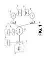
- FIG. 1is a block diagram of a functional architecture for a communications system, according to an embodiment of the invention
- FIG. 2is a flow diagram of a process for remotely managing a network, according to an embodiment of the invention
- FIG. 3is a flow diagram of a process for configuring a control unit, according to an embodiment of the invention.
- FIG. 4is a flow diagram of a process for configuring a proxy server, according to an embodiment of the invention.
- FIG. 5is a block diagram of a detailed functional architecture for a communications system according to an embodiment of the invention.
- FIG. 6is a flow diagram of a process for performing a communication session through a firewall, according to an embodiment of the invention.
- FIG. 1is a block diagram of a functional architecture for a communications system, according to an embodiment of the invention.
- a proxy server 105is coupled to console 120 and Internet 125 via a switch 110 .
- Internet 125is further coupled to firewall 135 , which is coupled to console 130 .
- firewall 140is coupled to control unit 150 via LAN 145 .
- Internet 125is also coupled to firewall 155 , which is coupled to control unit 165 via LAN 160 .
- Control units 150 and 165may also be coupled to other networks (not shown) or devices (not shown).
- Internet 125represents a public network.
- Internet 125can be replaced with a Wide Area Network (WAN), Local Area Network (LAN), or other publicly-accessible wired or wireless network, according to design choice.
- WANWide Area Network
- LANLocal Area Network
- LAN 145 and LAN 160represent enterprise networks that are inside (i.e., on the protected side) of firewalls 140 and 155 , respectively.
- LANs 145 and 160could be or include WANs or other network configurations, according to application requirements.
- Consoles 120 and 130each may be or include a personal computer, a desktop computer, a laptop computer, a Personal Digital Assistant (PDA), or other terminal or device suitable for handling necessary user interface functions. Moreover, consoles 120 and 130 each may include client software to facilitate operation in a networked environment.
- PDAPersonal Digital Assistant
- the control units 150 and 165may each include a central processing unit (CPU) (not shown), such as an Intel x86, Intel x86 compatible device, Intel PentiumTM, or other processor.
- the control units 150 and 165may each further include a hard disk or other storage device (not shown) for storing programs and/or data.
- control units 150 and 165may each have Random Access Memory (RAM), or other temporary memory (not shown) to execute Linux or other resident OS, and to execute application programs.
- Control units 150 and 165may include application code (not shown) for managing LANs 145 and 160 , respectively or for managing other networks (not shown) and/or devices (not shown).
- the control units 150 and 165may each be or include a network server.
- Control Units 150 and 165are inside (i.e., on the protected side) of firewalls 140 and 155 , respectively.
- Proxy server 105is a network-based server, and may include an Operating System (OS) (not shown), application code (not shown), and/or a database (not shown). In one respect, proxy server 105 provides access between each of consoles 120 and 130 and each of the control units 150 and 165 .
- Control unit 150may contain management data related to LAN 145 or other network (not shown) or network device (not shown), and control unit 165 may contain management data related to LAN 160 or other network (not shown) or network device (not shown).
- Proxy server 105may aggregate and store performance data provided by control units 150 and 165 , respectively. In operation, a user at either console 120 or 130 may provide commands to either or both of control units 150 and 165 via the proxy server 105 .
- proxy server 105is coupled to a public network.
- proxy server 105may be protected inside a firewall (not shown).
- proxy server 105may be implemented within a De-Militarized Zone (DMZ) between a protected network (not shown) and the unprotected Internet 125 or other public network.
- DMZDe-Militarized Zone
- the quantity of any component illustrated in FIG. 1may vary, according to application requirements.
- FIGS. 2-4illustrate enabling processes that can be performed using the functional architecture described above.
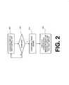
- FIG. 2is a flow diagram of a process for remotely managing a network, according to an embodiment of the invention.
- an overall processbegins in step 205 by configuring a first or next control unit. Step 205 is described in more detail below, with reference to FIG. 3 .
- conditional step 210it is determined whether all control units have been configured. Where the result of conditional step 210 is in the negative, the process returns to step 205 . If however, the result of conditional step 210 is in the affirmative, the process advances to step 215 to configure a proxy server. Step 215 is described in more detail below, with reference to FIG. 4 .
- step 220to execute a communication session between the control unit(s) and the proxy server.
- Step 220is described in more detail below, with reference to FIGS. 5 and 6 .
- conditional step 210is omitted.
- a communication sessioncan be executed in step 220 after a single control unit is configured in step 205 and after the proxy server is configured in step 215 .
- FIG. 3is a flow diagram of a process for configuring a control unit, according to an embodiment of the invention. The diagram is from the perspective of a control unit. As shown therein, the process begins in step 305 by receiving proxy server identification information.
- proxy server identification informationmay include, for example, server host name, IP address and logical port number.
- control unit 150 or 165may obtain the server IP address using an inquiry command directed to the proxy server 105 .
- Control unit 150 or 165sends the access key and control unit identification information to the proxy server 105 .
- Control unit identification informationmay include, for example, one or more of an external IP address and an internal IP address.
- control units 150 and 165are configured for remote communications with proxy server 105 .
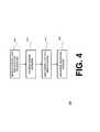
- FIG. 4is a flow diagram of a process for configuring a proxy server, according to an embodiment of the invention.
- the diagramis from the perspective of the proxy server 105 .
- the processbegins in step 405 by receiving control unit identification information from each of control units 150 and 165 .
- the proxy server 105stores the control unit information in a server database.
- the proxy server 105adds each of control units 150 and 165 as remote devices.
- a validation messagemay be exchanged between the proxy server 105 and each of the control units 150 and 165 to confirm the configuration of the control units and the server.
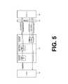
- FIG. 5is a block diagram of a detailed functional architecture for a communications system, according to an embodiment of the invention.
- a console 505is coupled to a proxy server 510 .
- the Proxy server 510is coupled to a control unit 520 through a firewall 515 .
- Proxy server 510includes client request handler 525 , shared request object pool 530 and server request handler 535 .
- a request object 540may be instantiated in any one or more of handler 525 , pool 530 , and handler 535 .
- multiple consolesmay be coupled to the proxy server 510 .
- consoles 120 and 130could be substituted for console 505 .
- the proxy server 510may be coupled to multiple control units through corresponding multiple firewalls.
- control units 150 and 165could be substituted for control unit 520
- firewalls 140 and 155could be substituted for firewall 515 .
- a proxy server 510may have the features described above with reference to proxy server 105 .
- FIG. 6is a flow diagram of a process for performing a communication session through a firewall, according to an embodiment of the invention.
- FIG. 6is illustrated from the perspective of a proxy server.
- the processbeings in step 605 by establishing a control port connection with a control unit.
- proxy server 510may establish a control port connection by receiving control port message 515 from the control unit 520 via firewall 515 .
- the port connectionmay be used, for example, to open and close data connections, and/or to provide security functions.
- the proxy server 510establishes a connection with a console, and receives a request from the console. For instance, after establishing a server/client link with the console, which may be or include a Secure Socket Layer (SSL) link, proxy server 510 may receive console request message 550 from console 505 .
- SSLSecure Socket Layer
- Console request message 550may be a request for network management data from control unit 520 related to LAN 145 , LAN 160 , other networks (not shown) coupled to control unit 150 and/or 165 , or network devices (not shown) coupled to control units 150 and/or 165 .
- console request message 550may be a request for IP-PBX status information, where an IP-PBX is coupled to control unit 150 and/or 165 .
- Console request message 550may be a request for status information related to an Uninterruptible Power Supply (UPS) or other network device coupled to control unit 150 and/or 165 .
- UPSUninterruptible Power Supply
- console request message 550may be a back-up, shut-down, re-start, or other control command directed to the control unit 150 and/or 165 , or to an IP-PBX coupled to one of control unit 150 and/or 165 , for example.
- step 615the proxy server 510 creates a request object having an identification (ID) number, where the request object is related to the console request.
- the proxy server 510adds the request object to a pool of one or more request objects.
- step 615may include creating request object 540 in client request handler 525 .
- Step 615may also include the assignment of ID number 0001 to request object 540 , and the addition of request object 540 to object pool 530 .
- step 620the proxy server 510 notifies the control unit of a pending request object, by ID number.
- proxy server 510could send request pending message 555 to control unit 520 with notice of pending request object 540 having ID number 0001 .
- the proxy drivercreates a data connection with the control unit, and receives a request from the control unit for a request object having a specific ID number.
- the data connectionmay be, for example, a TCP/IP socket, opened according to commands issued via the control port connection.
- proxy driver 510could receive a get request message 560 from the control unit 520 .
- the get request messagecould specifically request the request object 540 having ID number 0001 .
- the proxy driverretrieves the specified request object from the pool of one or more request objects.
- the server request handler 535could retrieve request 540 having specified ID number 0001 from the shared request object pool 530 .
- step 635the proxy driver sends the specified request object to the control unit.
- the request handler 535sends request 540 having the specified ID number 0001 to the control unit 520 as part of request message 565 .
- the proxy server 510receives a response to the specific request object from the control unit and closes the data connection with the control unit. For instance, in this step, the request handler 535 receives management data from the control unit 520 as part of control unit response message 570 .
- the proxy server 510sends the response to the console.
- request handler 535could send the management data to the console 505 as part of proxy server response message 575 .
- proxy server response message 575contains management data from control unit 520 that satisfies console request message 550 from the console 505 .
- the proxy server 510closes the connection with the console in step 650 , for example by ending the SSL link between the console 505 and the proxy server 510 .
- proxy server 510includes at least one processor
- the process illustrated in FIG. 6may be embodied in processor-executable code, the processor-executable code being executed by the at least one processor.
- the invention described abovethus overcomes the disadvantages of known systems and methods by facilitating the remote management of one or more networks without requiring modification to a firewall protecting the network to be managed, and without granting broad administrative privileges to external service providers. While this invention has been described in various explanatory embodiments, other embodiments and variations can be effected by a person of ordinary skill in the art without departing from the scope of the invention.
Landscapes
- Engineering & Computer Science (AREA)
- Computer Hardware Design (AREA)
- Computer Security & Cryptography (AREA)
- Computing Systems (AREA)
- General Engineering & Computer Science (AREA)
- Computer Networks & Wireless Communication (AREA)
- Signal Processing (AREA)
- Data Exchanges In Wide-Area Networks (AREA)
- Computer And Data Communications (AREA)
Abstract
Description
Claims (13)
Priority Applications (1)
| Application Number | Priority Date | Filing Date | Title |
|---|---|---|---|
| US10/721,753US7890995B2 (en) | 2003-11-26 | 2003-11-26 | System and method for remote management of communications networks |
Applications Claiming Priority (1)
| Application Number | Priority Date | Filing Date | Title |
|---|---|---|---|
| US10/721,753US7890995B2 (en) | 2003-11-26 | 2003-11-26 | System and method for remote management of communications networks |
Publications (2)
| Publication Number | Publication Date |
|---|---|
| US20050114665A1 US20050114665A1 (en) | 2005-05-26 |
| US7890995B2true US7890995B2 (en) | 2011-02-15 |
Family
ID=34591876
Family Applications (1)
| Application Number | Title | Priority Date | Filing Date |
|---|---|---|---|
| US10/721,753Active2027-01-16US7890995B2 (en) | 2003-11-26 | 2003-11-26 | System and method for remote management of communications networks |
Country Status (1)
| Country | Link |
|---|---|
| US (1) | US7890995B2 (en) |
Cited By (3)
| Publication number | Priority date | Publication date | Assignee | Title |
|---|---|---|---|---|
| US20130117841A1 (en)* | 2011-11-04 | 2013-05-09 | Sanken Electric Co., Ltd. | Information processing program and information processing method |
| US8806633B2 (en) | 2011-08-22 | 2014-08-12 | Cisco Technology, Inc. | Coordinated detection of a grey-hole attack in a communication network |
| US20220124119A1 (en)* | 2019-04-30 | 2022-04-21 | Paypal, Inc. | Proxy server and navigation code injection to prevent malicious messaging attacks |
Families Citing this family (5)
| Publication number | Priority date | Publication date | Assignee | Title |
|---|---|---|---|---|
| CA2555719C (en)* | 2005-10-31 | 2010-04-13 | Lpi Level Platforms, Inc. | A method for providing remote management of computer systems |
| US8453241B2 (en)* | 2006-12-18 | 2013-05-28 | Illinois Institute Of Technology | Method for securing streaming multimedia network transmissions |
| US20090070877A1 (en)* | 2006-12-18 | 2009-03-12 | Carol Davids | Method for securing streaming multimedia network transmissions |
| US8130677B2 (en)* | 2008-03-14 | 2012-03-06 | Aastra Technologies Limited | Method and system for configuring a network communications device |
| GB2523123B (en)* | 2014-02-12 | 2016-04-13 | Fijowave Ltd | Method and hardware device for remotely connecting to and controlling a private branch exchange |
Citations (28)
| Publication number | Priority date | Publication date | Assignee | Title |
|---|---|---|---|---|
| US6104716A (en)* | 1997-03-28 | 2000-08-15 | International Business Machines Corporation | Method and apparatus for lightweight secure communication tunneling over the internet |
| US6182086B1 (en)* | 1998-03-02 | 2001-01-30 | Microsoft Corporation | Client-server computer system with application recovery of server applications and client applications |
| US6292801B1 (en)* | 1998-10-02 | 2001-09-18 | Rene L. Campbell | System and method for managing computer and phone network resources |
| US6341311B1 (en)* | 1998-05-29 | 2002-01-22 | Microsoft Corporation | Directing data object access requests in a distributed cache |
| US6349336B1 (en)* | 1999-04-26 | 2002-02-19 | Hewlett-Packard Company | Agent/proxy connection control across a firewall |
| US6360273B1 (en)* | 1998-02-23 | 2002-03-19 | International Business Machines Corporation | Method for collaborative transformation and caching of web objects in a proxy network |
| US20020038364A1 (en)* | 2000-06-12 | 2002-03-28 | Limor Schweitzer | System, method and computer program product for reading, correlating, processing, categorizing and aggregating events of any type |
| US6374298B2 (en)* | 1995-05-19 | 2002-04-16 | Fujitsu Limited | System for performing remote operation between firewall-equipped networks or devices |
| US20020159440A1 (en)* | 2001-04-30 | 2002-10-31 | Mussman Harry Edward | Screening inbound calls in a packet-based communications network |
| US20030009464A1 (en)* | 1998-10-02 | 2003-01-09 | Campbell Rene L. | System and method for managing computer and phone network resources |
| US6510464B1 (en)* | 1999-12-14 | 2003-01-21 | Verizon Corporate Services Group Inc. | Secure gateway having routing feature |
| US6553422B1 (en)* | 1999-04-26 | 2003-04-22 | Hewlett-Packard Development Co., L.P. | Reverse HTTP connections for device management outside a firewall |
| US6651174B1 (en)* | 1998-05-27 | 2003-11-18 | Ntt Comware Corporation | Firewall port switching |
| US20040001479A1 (en)* | 2002-07-01 | 2004-01-01 | Pounds Gregory E. | Systems and methods for voice and data communications including a network drop and insert interface for an external data routing resource |
| US6751738B2 (en)* | 1996-10-17 | 2004-06-15 | Ralph E. Wesinger, Jr. | Firewall providing enhanced network security and user transparency |
| US6754831B2 (en)* | 1998-12-01 | 2004-06-22 | Sun Microsystems, Inc. | Authenticated firewall tunneling framework |
| US20040139209A1 (en)* | 2003-01-09 | 2004-07-15 | Mussman Harry Edward | Routing calls through a network |
| US20040161086A1 (en)* | 1998-12-11 | 2004-08-19 | Securelogix Corporation | Telephony security system |
| US20040260747A1 (en)* | 2003-06-19 | 2004-12-23 | Sbc, Inc. | Method and apparatus for Voice over Internet Protocol telephony using a virtual private network |
| US20050008006A1 (en)* | 2003-07-02 | 2005-01-13 | Thomas Schimper | Method for operating a voice terminal connected to a remote private automatic branch exchange, communication arrangement and voice terminal |
| US6968571B2 (en)* | 1997-09-26 | 2005-11-22 | Mci, Inc. | Secure customer interface for web based data management |
| US6996076B1 (en)* | 2001-03-29 | 2006-02-07 | Sonus Networks, Inc. | System and method to internetwork wireless telecommunication networks |
| US20060031936A1 (en)* | 2002-04-04 | 2006-02-09 | Enterasys Networks, Inc. | Encryption security in a network system |
| US7099301B1 (en)* | 1999-07-13 | 2006-08-29 | Innomedia, Inc. | Voice over internet protocol proxy gateway |
| US7107609B2 (en)* | 2001-07-20 | 2006-09-12 | Hewlett-Packard Development Company, L.P. | Stateful packet forwarding in a firewall cluster |
| US7239629B1 (en)* | 1999-12-01 | 2007-07-03 | Verizon Corporate Services Group Inc. | Multiservice network |
| US7254832B1 (en)* | 2000-08-28 | 2007-08-07 | Nortel Networks Limited | Firewall control for secure private networks with public VoIP access |
| US7257837B2 (en)* | 2003-07-26 | 2007-08-14 | Innomedia Pte | Firewall penetration system and method for real time media communications |
- 2003
- 2003-11-26USUS10/721,753patent/US7890995B2/enactiveActive
Patent Citations (31)
| Publication number | Priority date | Publication date | Assignee | Title |
|---|---|---|---|---|
| US6374298B2 (en)* | 1995-05-19 | 2002-04-16 | Fujitsu Limited | System for performing remote operation between firewall-equipped networks or devices |
| US6751738B2 (en)* | 1996-10-17 | 2004-06-15 | Ralph E. Wesinger, Jr. | Firewall providing enhanced network security and user transparency |
| US6104716A (en)* | 1997-03-28 | 2000-08-15 | International Business Machines Corporation | Method and apparatus for lightweight secure communication tunneling over the internet |
| US6968571B2 (en)* | 1997-09-26 | 2005-11-22 | Mci, Inc. | Secure customer interface for web based data management |
| US6360273B1 (en)* | 1998-02-23 | 2002-03-19 | International Business Machines Corporation | Method for collaborative transformation and caching of web objects in a proxy network |
| US6182086B1 (en)* | 1998-03-02 | 2001-01-30 | Microsoft Corporation | Client-server computer system with application recovery of server applications and client applications |
| US6651174B1 (en)* | 1998-05-27 | 2003-11-18 | Ntt Comware Corporation | Firewall port switching |
| US6341311B1 (en)* | 1998-05-29 | 2002-01-22 | Microsoft Corporation | Directing data object access requests in a distributed cache |
| US6292801B1 (en)* | 1998-10-02 | 2001-09-18 | Rene L. Campbell | System and method for managing computer and phone network resources |
| US20030009464A1 (en)* | 1998-10-02 | 2003-01-09 | Campbell Rene L. | System and method for managing computer and phone network resources |
| US6754831B2 (en)* | 1998-12-01 | 2004-06-22 | Sun Microsystems, Inc. | Authenticated firewall tunneling framework |
| US20040161086A1 (en)* | 1998-12-11 | 2004-08-19 | Securelogix Corporation | Telephony security system |
| US7133511B2 (en)* | 1998-12-11 | 2006-11-07 | Securelogix Corporation | Telephony security system |
| US6553422B1 (en)* | 1999-04-26 | 2003-04-22 | Hewlett-Packard Development Co., L.P. | Reverse HTTP connections for device management outside a firewall |
| US6349336B1 (en)* | 1999-04-26 | 2002-02-19 | Hewlett-Packard Company | Agent/proxy connection control across a firewall |
| US7099301B1 (en)* | 1999-07-13 | 2006-08-29 | Innomedia, Inc. | Voice over internet protocol proxy gateway |
| US7239629B1 (en)* | 1999-12-01 | 2007-07-03 | Verizon Corporate Services Group Inc. | Multiservice network |
| US6510464B1 (en)* | 1999-12-14 | 2003-01-21 | Verizon Corporate Services Group Inc. | Secure gateway having routing feature |
| US20020038364A1 (en)* | 2000-06-12 | 2002-03-28 | Limor Schweitzer | System, method and computer program product for reading, correlating, processing, categorizing and aggregating events of any type |
| US7254832B1 (en)* | 2000-08-28 | 2007-08-07 | Nortel Networks Limited | Firewall control for secure private networks with public VoIP access |
| US6996076B1 (en)* | 2001-03-29 | 2006-02-07 | Sonus Networks, Inc. | System and method to internetwork wireless telecommunication networks |
| US7075922B2 (en)* | 2001-04-30 | 2006-07-11 | Level 3 Communications, Inc. | Screening inbound calls in a packet-based communications network |
| US20020159440A1 (en)* | 2001-04-30 | 2002-10-31 | Mussman Harry Edward | Screening inbound calls in a packet-based communications network |
| US7107609B2 (en)* | 2001-07-20 | 2006-09-12 | Hewlett-Packard Development Company, L.P. | Stateful packet forwarding in a firewall cluster |
| US20060031936A1 (en)* | 2002-04-04 | 2006-02-09 | Enterasys Networks, Inc. | Encryption security in a network system |
| US20040001479A1 (en)* | 2002-07-01 | 2004-01-01 | Pounds Gregory E. | Systems and methods for voice and data communications including a network drop and insert interface for an external data routing resource |
| US20040139209A1 (en)* | 2003-01-09 | 2004-07-15 | Mussman Harry Edward | Routing calls through a network |
| US7363381B2 (en)* | 2003-01-09 | 2008-04-22 | Level 3 Communications, Llc | Routing calls through a network |
| US20040260747A1 (en)* | 2003-06-19 | 2004-12-23 | Sbc, Inc. | Method and apparatus for Voice over Internet Protocol telephony using a virtual private network |
| US20050008006A1 (en)* | 2003-07-02 | 2005-01-13 | Thomas Schimper | Method for operating a voice terminal connected to a remote private automatic branch exchange, communication arrangement and voice terminal |
| US7257837B2 (en)* | 2003-07-26 | 2007-08-14 | Innomedia Pte | Firewall penetration system and method for real time media communications |
Cited By (5)
| Publication number | Priority date | Publication date | Assignee | Title |
|---|---|---|---|---|
| US8806633B2 (en) | 2011-08-22 | 2014-08-12 | Cisco Technology, Inc. | Coordinated detection of a grey-hole attack in a communication network |
| US20130117841A1 (en)* | 2011-11-04 | 2013-05-09 | Sanken Electric Co., Ltd. | Information processing program and information processing method |
| US9128738B2 (en)* | 2011-11-04 | 2015-09-08 | Sanken Electric Co., Ltd. | Information processing program and information processing method |
| US20220124119A1 (en)* | 2019-04-30 | 2022-04-21 | Paypal, Inc. | Proxy server and navigation code injection to prevent malicious messaging attacks |
| US11838320B2 (en)* | 2019-04-30 | 2023-12-05 | Paypal, Inc. | Proxy server and navigation code injection to prevent malicious messaging attacks |
Also Published As
| Publication number | Publication date |
|---|---|
| US20050114665A1 (en) | 2005-05-26 |
Similar Documents
| Publication | Publication Date | Title |
|---|---|---|
| US7536392B2 (en) | Network update manager | |
| US8239520B2 (en) | Network service operational status monitoring | |
| US9258308B1 (en) | Point to multi-point connections | |
| US9407456B2 (en) | Secure access to remote resources over a network | |
| US7904712B2 (en) | Service licensing and maintenance for networks | |
| US20060126603A1 (en) | Information terminal remote operation system, remote access terminal, gateway server, information terminal control apparatus, information terminal apparatus, and remote operation method therefor | |
| WO2003100638A1 (en) | Network resource management system | |
| US20060294580A1 (en) | Administration of access to computer resources on a network | |
| CA2514004C (en) | System and method for controlling network access | |
| JP2004072766A (en) | System for providing access control platform service to private network | |
| KR20040103441A (en) | Controlled relay of media streams across network perimeters | |
| EP1788778B1 (en) | Network system, proxy server, session management method, and respective program | |
| KR102312019B1 (en) | Firewall control device and firewall policy management system including the same | |
| US6651174B1 (en) | Firewall port switching | |
| WO2017067385A1 (en) | Methods, systems, and apparatuses of service provisioning for resource management in a constrained environment | |
| US20090024750A1 (en) | Managing remote host visibility in a proxy server environment | |
| US6754212B1 (en) | Repeater and network system utililzing the same | |
| US7890995B2 (en) | System and method for remote management of communications networks | |
| US20060150243A1 (en) | Management of network security domains | |
| US20070136471A1 (en) | Systems and methods for negotiating and enforcing access to network resources | |
| CN111988269A (en) | Policy management system providing authorization information via distributed data stores | |
| EP1973270B1 (en) | Broadband service delivery | |
| US20070136301A1 (en) | Systems and methods for enforcing protocol in a network using natural language messaging | |
| US20070136472A1 (en) | Systems and methods for requesting protocol in a network using natural language messaging | |
| KR102618291B1 (en) | Client asset management system and client asset management method |
Legal Events
| Date | Code | Title | Description |
|---|---|---|---|
| AS | Assignment | Owner name:QOVIA, INC., MARYLAND Free format text:ASSIGNMENT OF ASSIGNORS INTEREST;ASSIGNORS:SHIM, CHOON B.;TWOREK, RICHARD M.;REEL/FRAME:015268/0621 Effective date:20040325 | |
| AS | Assignment | Owner name:CISCO SYSTEMS, INC., CALIFORNIA Free format text:ASSIGNMENT OF ASSIGNORS INTEREST;ASSIGNOR:QOVIA, INC.;REEL/FRAME:020208/0156 Effective date:20070202 Owner name:CISCO SYSTEMS, INC.,CALIFORNIA Free format text:ASSIGNMENT OF ASSIGNORS INTEREST;ASSIGNOR:QOVIA, INC.;REEL/FRAME:020208/0156 Effective date:20070202 | |
| AS | Assignment | Owner name:CISCO TECHNOLOGY, INC., CALIFORNIA Free format text:ASSIGNMENT OF ASSIGNORS INTEREST;ASSIGNOR:CISCO SYSTEMS, INC.;REEL/FRAME:020860/0257 Effective date:20071210 Owner name:CISCO TECHNOLOGY, INC.,CALIFORNIA Free format text:ASSIGNMENT OF ASSIGNORS INTEREST;ASSIGNOR:CISCO SYSTEMS, INC.;REEL/FRAME:020860/0257 Effective date:20071210 | |
| FEPP | Fee payment procedure | Free format text:PAYOR NUMBER ASSIGNED (ORIGINAL EVENT CODE: ASPN); ENTITY STATUS OF PATENT OWNER: LARGE ENTITY | |
| STCF | Information on status: patent grant | Free format text:PATENTED CASE | |
| CC | Certificate of correction | ||
| FPAY | Fee payment | Year of fee payment:4 | |
| MAFP | Maintenance fee payment | Free format text:PAYMENT OF MAINTENANCE FEE, 8TH YEAR, LARGE ENTITY (ORIGINAL EVENT CODE: M1552); ENTITY STATUS OF PATENT OWNER: LARGE ENTITY Year of fee payment:8 | |
| MAFP | Maintenance fee payment | Free format text:PAYMENT OF MAINTENANCE FEE, 12TH YEAR, LARGE ENTITY (ORIGINAL EVENT CODE: M1553); ENTITY STATUS OF PATENT OWNER: LARGE ENTITY Year of fee payment:12 |