US7890915B2 - Statistical delay and noise calculation considering cell and interconnect variations - Google Patents
Statistical delay and noise calculation considering cell and interconnect variationsDownload PDFInfo
- Publication number
- US7890915B2 US7890915B2US11/918,760US91876006AUS7890915B2US 7890915 B2US7890915 B2US 7890915B2US 91876006 AUS91876006 AUS 91876006AUS 7890915 B2US7890915 B2US 7890915B2
- Authority
- US
- United States
- Prior art keywords
- calculating
- variations
- effective capacitance
- statistical
- variation
- Prior art date
- Legal status (The legal status is an assumption and is not a legal conclusion. Google has not performed a legal analysis and makes no representation as to the accuracy of the status listed.)
- Active, expires
Links
Images


Classifications
- G—PHYSICS
- G06—COMPUTING OR CALCULATING; COUNTING
- G06F—ELECTRIC DIGITAL DATA PROCESSING
- G06F30/00—Computer-aided design [CAD]
- G06F30/30—Circuit design
- G06F30/32—Circuit design at the digital level
- G06F30/33—Design verification, e.g. functional simulation or model checking
- G06F30/3308—Design verification, e.g. functional simulation or model checking using simulation
- G06F30/3312—Timing analysis
Definitions
- the inventiongenerally relates to the field of integrated circuit design performance analysis and optimization, and particularly to the delay and crosstalk noise calculation for logic cells used in statistical static timing analysis of digital integrated circuit.
- VLSIvery large-scale integrated circuit
- EDAElectronic Design Automation
- Two main methodologies for timing verificationare used: 1) transistor-level simulation based method and 2) cell/gate-level static timing analysis.
- the transistor-level simulation methodcan accurately simulate the circuit timing behavior, but this method is very time-consuming and is not feasible for a full-chip analysis.
- Static timing analysisprovides a fast method to estimate circuit timing performance, and can be used for full-chip analysis.
- logic cellsare the basic building blocks; logic cells are interconnected with metal wires.
- logic cell delay modelsare becoming more and more complicated as semiconductor technologies evolve.
- cell delayscould be modeled as a constant number.
- CMOS technologieswere widely used, and cell delays became a function of input transition time and load capacitance.
- gate and RCresistance capacitance
- a coupled interconnect systemincludes a victim net and several aggressor nets.
- a netis a set of nodes resistively connected.
- a nethas one driver node, one or more fanout nodes, and may have a number of intermediate nodes that are part of the interconnect. “Fanout” is the ability of a logic gate to drive further logic gates; fanout refers to or is quantified by referring to the number of gates before voltage falloff causes errors.
- An “aggressor net”is a net that has significant coupling capacitance to the victim net so as to be able to influence the delay of the victim gate.
- a gateis a logic unit or cell. Each net has its ground capacitances, and there are coupling capacitances between different nets. When circuit feature size decreases, the space between interconnects is reduced and the ratio of coupling capacitance and substrate capacitance increases proportionally.
- crosstalk effectThe effects of crosstalk (“crosstalk effect”) pose two major problems.
- capacitive crosstalkcan induce noise (glitches) and potentially cause functional failures. For example, if a glitch happens when the clock signal of a register is switching, the data in the register may be flipped accidentally.
- crosstalkcan change the delay of the victim if the aggressor is also switching. If the aggressor is switching in the opposite direction, crosstalk can lead to an increase in delay, which may cause “setup time violations.” If the aggressor is switching in the same direction as the victim, crosstalk may lead to the delay decreasing, and may cause “hold time violations.”
- the inventionprovides a sensitivity-based statistical delay calculation methodology.
- the inventive methodprovides accurate nominal delay together with the delay sensitivities with respect to different circuit elements (e.g., cells, interconnects, etc.) and variational parameters such as fabrication process and environmental variations.
- the inventionprovides a statistical delay calculation methodology, which can efficiently calculate nominal delay and its sensitivity over different parameters.
- all the sensitivity computationsare based on closed-form formulas; consequently, the inventive method provides, rapidly and at low cost, high accuracy and high numerical stability.
- the inventionalso provides a method for calculating waveform-based statistical noise and cross-talk delay.
- the methodcan accurately calculate statistical noise waveform and its impact on delay.
- the invention taught hereinapplies statistical Max and Sum operations to statistical noise waveform and noise envelope calculations.
- the invention taught hereinis broadly represented in FIG. 1 .
- the inventionprovides statistical delay calculation 302 considering non-linear cell input noise waveform and receiver capacitance.
- the inventionfurther provides statistical noise calculation 304 considering non-linear victim driver resistance model and multiple timing windows.
- the inventionfurther provides statistical crosstalk delay calculation 306 combining non-cross-talk statistical delay and statistical noise information—using pure analytical approaches and guaranteeing pessimism.
- the inventive method of calculating delaycomprises a first step of calculating a statistical driving circuit, and includes the sub-steps of calculating statistical compact interconnect load; calculating nominal effective capacitance through an equilibrium equation; and calculating statistical driving Thevenin/Norton circuit.
- the inventionfarther provides for determining statistical delay and transition by: calculating the statistical transfer function to fanout pins; calculating the statistical voltage waveforms at the fanout pins; and calculating the statistical delay and the transition from the waveforms.
- the inventive methodfurther provides the step of statistical noise calculation including the sub-steps of: a) calculating statistical noise waveform and envelope for a given input pin of a given aggressor cell; b) repeating Step a for all input pins of a given aggressor cell; c) calculating the statistical Max of the noise envelopes from all input pins of a given aggressor cell; d) repeating Step c for all aggressor cells; e) calculating the statistical Sum of the noise envelopes from all aggressors cells.
- Also taught is a method of crosstalk delay calculationthat includes the steps of: calculating statistical output waveform as the statistical Sum of the statistical fanout waveform of the victim cell (the value of the statistical fanout waveform from the victim cell is provided by the delay calculation of the method taught herein) and statistical noise waveform from the aggressor cells (the value of the statistical noise waveform from the aggressor cells is provided by the noise calculation of the method taught herein) and calculating crosstalk delay from statistical waveform using an equation
- system and methodmay be implemented via software—computer readable media—or any configuration of components capable of delivering instructions to a central processing unit of any computing device.
- an apparatus for performing the invention as well as a product resulting from the inventionare within the scope of the teaching and claims.
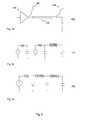
- FIG. 1is a summary chart of the invention taught herein, and some components (statistical delay calculation, statistical noise calculation, statistical crosstalk delay evaluation) and relationships of those components in the preferred embodiment.
- FIG. 2 a - cillustrates the main steps in the method of statistical delay calculation, which includes statistical driving circuit constructing and statistical fanout waveform and delay/transition calculation.
- FIG. 3 a - bis pseudo code representing the method of statistical delay calculation.
- FIG. 4is a flow chart depicting the steps of FIG. 2 a - c and FIG. 3 a - b according to the preferred embodiment.
- FIG. 5 a - c inclusiveillustrates the main steps of the method for statistical noise and statistical crosstalk delay calculation, including noise/envelope statistical operation and worst case crosstalk delay calculations.
- FIG. 6 a - binclusive, is pseudo code representing the method for determining statistical noise and crosstalk delay.
- FIG. 7is a flow chart depicting the steps of FIG. 5 a - c and FIG. 6 a - b according to the preferred embodiment.
- the invention taught hereinis broadly represented in FIG. 1 .
- the inventionprovides a method of determining statistical delay 302 considering non-linear input waveform and receiver capacitance.
- the inventionfurther provides a method for statistical noise calculation 304 considering non-linear victim driver resistance model and multiple timing windows.
- the inventionfurther provides statistical crosstalk delay calculation 306 combining non-cross-talk statistical delay and statistical noise information using pure analytical approaches and guarantee pessimism (i.e., satisfying a verification condition ensuring the IC chip circuits function).
- Cell delayis a function of different physical sources.
- Cell delayis a function of non-linear input waveform, non-linear receiver load capacitances, resistive interconnect load, crosstalk effect and process and environmental variations.
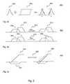
- FIG. 2sketches the concepts underlying the steps to determine statistical delay.
- FIG. 3provides pseudocode for the inventive approach diagrammed in FIG. 2 ;
- FIG. 4depicts the steps of the approach as in FIG. 2 and FIG. 3 in a flow chart.
- a statistical ⁇ circuit load modelis constructed from the statistical interconnect information.
- the statistical ⁇ circuit load modelis used to calculate the statistical Thevenin model through using the inventive equilibrium point equations; the equations include the sensitivities over input slope, cell process parameters and ⁇ load.
- FIG. 2 a ( 400 )represents a total circuit; logic circuit 402 ; a first waveform 404 ; an interconnect (RC) 406 ; a second waveform 408 .
- FIG. 2 b ( 410 )(and see FIG.
- the stepsare shown in FIG. 4 : statistical driving circuit calculation 80 including the sub-steps of calculating the statistical compact interconnect load 82 ; calculating the nominal effective capacitance through an equilibrium equation 84 ; and calculating the statistical driving Thevenin/Norton circuit 86 .
- the interconnect 406is then attached to the linear gate model (see FIG. 2 b ) and a statistical linear circuit evaluation is performed to calculate the statistical fanout delay and slope (see FIG. 2 c ( 412 )) (and see FIG. 3 b ).
- the stepsare shown in FIG. 4 , statistical delay and transition calculation 90 and include the substeps of: calculating statistical transfer function to fanout pins 92 ; calculating statistical voltage waveforms at fanout pins 94 ; and calculating statistical delay and transition from waveforms 96 .
- the preferred embodiment of the invention as regards delay calculationincludes the steps as set forth herein. Initially, a statistical Thevenin model is constructed from statistical Effective Capacitance evaluation. Then a nominal Ceff evaluation is performed to construct an equivalent Thevenin model. (A detailed nominal Ceff evaluation process can be found in Mustafa Celik, Lawrence Pileggi and Altan Odabasioglu, “IC Interconnect Analysis”, Kluwer Academic Publishers, 2002 (incorporated by reference as if fully set forth herein)).
- the derivationis omitted and the resulting equation shown—the final average current expression for both ⁇ load and Ceff load from our modified nominal Ceff calculation.
- An equivalent Thevenin modelcan be computed by iteratively matching these two equations. As is shown in equations (1) and (2), to avoid unstable numerical computation, the inventive method improves the nominal Ceff evaluation by expressing the average current in turns of time constant.
- i ⁇⁇ ⁇ ⁇ ( 1 + k ⁇ 1 ⁇ ⁇ 1 ⁇ ⁇ ( e - ⁇ ⁇ 1 - 1 ) + k ⁇ 2 ⁇ ⁇ 2 ⁇ ⁇ ( e - ⁇ ⁇ 2 - 1 ) ) ( 1 )
- i ceffc eff ⁇ ⁇ ( 1 + ⁇ ⁇ ⁇ ( e - ⁇ ⁇ - 1 ) ) ( 2 )
- Equation (4)shows the formula of fanout waveform with two-pole approximation:
- v ⁇ ( t )⁇ k 1 ⁇ ⁇ p 1 2 ⁇ ( e p 1 ⁇ t - 1 - p 1 ⁇ t ) + k 2 ⁇ ⁇ p 2 2 ⁇ ( e p 2 ⁇ t - 1 - p 2 ⁇ t ) ( t ⁇ ⁇ ) k 1 ⁇ ⁇ p 1 2 ⁇ ( e p 1 ⁇ t - e p 1 ⁇ ( t - ⁇ ) - p 1 ⁇ ⁇ ) + k 2 ⁇ ⁇ p 2 2 ⁇ ( e p 2 ⁇ t - e p 2 ⁇ ( t - ⁇ ) - p 2 ⁇ ⁇ ) ( t > ⁇ ) ( 4 )
- the inventionprovides a novel method for statistical noise analysis and crosstalk delay calculation (see FIG. 1 , 306 ).
- the methodnaturally combines aggressor timing window with noise waveform to reduce pessimism. It also takes into account the process variations from both aggressor and victim net driving cell.
- FIG. 6presents pseudocode expressing the main steps for statistical noise and crosstalk delay calculations according to the preferred embodiment.
- FIG. 7is a flow chart showing the steps for statistical noise calculation.
- the aggressor netWhen the aggressor net is switching, its driving cell can be modeled as a Thevenin linear circuit. And the transfer function from aggressor driver pin to victim fanout pin can be calculated using moment-based methods. If we assume the transition time of the aggressor voltage source is ⁇ , and the transfer function is modeled as a two-pole function where p1, p2, k1, k2 are corresponding poles and residues, the fanout noise waveform can be calculated using the following equations:
- v ⁇ ( t )⁇ k 1 ⁇ ⁇ p 1 ⁇ ( e p 1 ⁇ t - 1 ) + k 2 ⁇ ⁇ p 2 ⁇ ( e p 2 ⁇ t - 1 ) ( t ⁇ ⁇ ) k 1 ⁇ ⁇ p 1 ⁇ ( e p 1 ⁇ t - e p 1 ⁇ ( t - ⁇ ) ) + k 2 ⁇ ⁇ p 2 ⁇ ( e p 2 ⁇ t - e p 2 ⁇ ( t - ⁇ ) ) ( t > ⁇ ) ( 6 )
- the exact switching time at a timing nodeis not known: only the earliest/latest arrival time is available.
- the aggressor cell/net input pincan switch at any time in this period between the earliest and the latest time available.
- a single noise envelope(see FIG. 5 a , 606 ) from a noise waveform 602 and a timing window 604 represents the worst case noise peak from a single aggressor.
- MaxThere are two basic operations for noise envelope combination: Max and Sum. As shown in FIG. 5 b , the Max 612 operation takes the bigger value of the envelope over the total time interval, while the Sum 626 operation adds two envelopes 622 , 624 together to create a new envelope 628 .
- the Sum operationis used to combine noise envelopes that come from all the aggressor nets and drivers.
- the Max operationis used to combine noise envelopes that come from all the input pins of each aggressor driver.
- Statistical noise calculation according to the present inventionappears as a flow chart in FIG. 7 .
- the steps for statistical noise calculation 900include the substeps of:
- PDFprobability density function
- CDFcumulative distribution function
- the step of statistical crosstalk delay calculation 930includes the sub-steps of:
- td i- v i ⁇ ( td ) + n i ⁇ ( td ) ⁇ v ⁇ ( td ) / ⁇ td + ⁇ v ⁇ ( td ) / ⁇ td ( 8 )
- Crosstalk delayis a function of both noise waveform and original fanout waveform. Once available, total statistical noise waveform and statistical fanout waveform can be combined to calculate statistical crosstalk delay as a linear function of different process variables.
- Theorem 1can be proved by combining the statistical transition waveform and noise waveform and applying the chain rule. Because the transition waveform and the noise waveform both include statistical information, using Equation (9) we can easily calculate statistical crosstalk delay distributions.
- system and methodmay be implemented via software—computer readable media—or in any configuration enabling the delivery of instructions for practicing the invention to any central processing unit of any suitable computing device.
- an apparatus for performing the invention as well as a product resulting from the inventionare within the scope of the teaching and claims.
Landscapes
- Engineering & Computer Science (AREA)
- Computer Hardware Design (AREA)
- Physics & Mathematics (AREA)
- Theoretical Computer Science (AREA)
- Evolutionary Computation (AREA)
- Geometry (AREA)
- General Engineering & Computer Science (AREA)
- General Physics & Mathematics (AREA)
- Design And Manufacture Of Integrated Circuits (AREA)
Abstract
Description
where td=time delay, v=voltage and n=noise.
Ceff(si,π,w)=F(π,Ceff,S(si,w,Ceff),T(si,w,Ceff)) (3)
Statistical Noise and Crosstalk Delay Calculation
- a) Calculating statistical noise waveform and envelope for a given input pin of a given
aggressor cell 905; - b) Repeating Step a for all input pins of the
aggressor cell 910; - c) Calculating the statistical Max of the envelopes from all input pins of a given
aggressor cell 915; - d) Repeating Step c for all
aggressors cells 920; - e) Calculating the statistical Sum of noise envelopes from all
aggressor cells 925.
- a) Calculating statistical noise waveform and envelope for a given input pin of a given
| Theorem 1: Given victim fanout voltage waveform v(t) = v0(t) + |
| v1(t) · p1+ v2(t) · p2+ . . . vi(t) · pi. . . |
| and noise waveform at the same fanout n(t) = n0(t) + |
| n1(t) · p1+ n2(t) · p2+ . . . ni(t) · pi. . . , where (p1, p2. . . ) |
| are a set of independent normal random variables, the statistical |
| crosstalk delay td at that fanout can be calculated as td = td0+ |
| td1· p1+ td2· p2+ . . . tdi· pi. . . and |
| (9) | |
Claims (3)
Ceff(si,π,w)=F(π,Ceff,S(si,w,Ceff),T(si,w,Ceff)) (3)
Ceff(si,π,w)=F(π,Ceff,S(si,w,Ceff),T(si,w,Ceff)) (3)
Ceff(si,π,w)=F(π,Ceff,S(si,w,Ceff),T(si,w,Ceff)) (3)
Priority Applications (1)
| Application Number | Priority Date | Filing Date | Title |
|---|---|---|---|
| US11/918,760US7890915B2 (en) | 2005-03-18 | 2006-03-17 | Statistical delay and noise calculation considering cell and interconnect variations |
Applications Claiming Priority (3)
| Application Number | Priority Date | Filing Date | Title |
|---|---|---|---|
| US66321905P | 2005-03-18 | 2005-03-18 | |
| US11/918,760US7890915B2 (en) | 2005-03-18 | 2006-03-17 | Statistical delay and noise calculation considering cell and interconnect variations |
| PCT/US2006/009634WO2006102027A1 (en) | 2005-03-18 | 2006-03-17 | Statistical delay and noise calculation considering cell and interconnect variations |
Publications (2)
| Publication Number | Publication Date |
|---|---|
| US20090288050A1 US20090288050A1 (en) | 2009-11-19 |
| US7890915B2true US7890915B2 (en) | 2011-02-15 |
Family
ID=37024135
Family Applications (1)
| Application Number | Title | Priority Date | Filing Date |
|---|---|---|---|
| US11/918,760Active2026-11-05US7890915B2 (en) | 2005-03-18 | 2006-03-17 | Statistical delay and noise calculation considering cell and interconnect variations |
Country Status (3)
| Country | Link |
|---|---|
| US (1) | US7890915B2 (en) |
| EP (1) | EP1866760A4 (en) |
| WO (1) | WO2006102027A1 (en) |
Cited By (92)
| Publication number | Priority date | Publication date | Assignee | Title |
|---|---|---|---|---|
| US20090193373A1 (en)* | 2008-01-29 | 2009-07-30 | Soroush Abbaspour | Multiple voltage threshold timing analysis for a digital integrated circuit |
| US20090299719A1 (en)* | 2008-05-27 | 2009-12-03 | Fujitsu Limited | Circuit simulation apparatus and method,medium containing circuit simulation program |
| US20100287517A1 (en)* | 2009-05-06 | 2010-11-11 | Dennis Darcy Buss | Statistical Static Timing Analysis in Non-Linear Regions |
| US8543954B1 (en)* | 2007-08-31 | 2013-09-24 | Cadence Design Systems, Inc. | Concurrent noise and delay modeling of circuit stages for static timing analysis of integrated circuit designs |
| US8595669B1 (en)* | 2007-08-31 | 2013-11-26 | Cadence Design Systems, Inc. | Flexible noise and delay modeling of circuit stages for static timing analysis of integrated circuit designs |
| US20160274759A1 (en) | 2008-08-25 | 2016-09-22 | Paul J. Dawes | Security system with networked touchscreen and gateway |
| US9898564B2 (en) | 2014-01-15 | 2018-02-20 | Sage Software, Inc. | SSTA with non-gaussian variation to second order for multi-phase sequential circuit with interconnect effect |
| US10051078B2 (en) | 2007-06-12 | 2018-08-14 | Icontrol Networks, Inc. | WiFi-to-serial encapsulation in systems |
| US10062273B2 (en) | 2010-09-28 | 2018-08-28 | Icontrol Networks, Inc. | Integrated security system with parallel processing architecture |
| US10062245B2 (en) | 2005-03-16 | 2018-08-28 | Icontrol Networks, Inc. | Cross-client sensor user interface in an integrated security network |
| US10079839B1 (en) | 2007-06-12 | 2018-09-18 | Icontrol Networks, Inc. | Activation of gateway device |
| US10078958B2 (en) | 2010-12-17 | 2018-09-18 | Icontrol Networks, Inc. | Method and system for logging security event data |
| US10091014B2 (en) | 2005-03-16 | 2018-10-02 | Icontrol Networks, Inc. | Integrated security network with security alarm signaling system |
| US10127801B2 (en) | 2005-03-16 | 2018-11-13 | Icontrol Networks, Inc. | Integrated security system with parallel processing architecture |
| US10142166B2 (en) | 2004-03-16 | 2018-11-27 | Icontrol Networks, Inc. | Takeover of security network |
| US10140840B2 (en) | 2007-04-23 | 2018-11-27 | Icontrol Networks, Inc. | Method and system for providing alternate network access |
| US10142394B2 (en) | 2007-06-12 | 2018-11-27 | Icontrol Networks, Inc. | Generating risk profile using data of home monitoring and security system |
| US10142392B2 (en) | 2007-01-24 | 2018-11-27 | Icontrol Networks, Inc. | Methods and systems for improved system performance |
| US10156831B2 (en) | 2004-03-16 | 2018-12-18 | Icontrol Networks, Inc. | Automation system with mobile interface |
| US10200504B2 (en) | 2007-06-12 | 2019-02-05 | Icontrol Networks, Inc. | Communication protocols over internet protocol (IP) networks |
| US10237237B2 (en) | 2007-06-12 | 2019-03-19 | Icontrol Networks, Inc. | Communication protocols in integrated systems |
| US10237806B2 (en) | 2009-04-30 | 2019-03-19 | Icontrol Networks, Inc. | Activation of a home automation controller |
| US10313303B2 (en) | 2007-06-12 | 2019-06-04 | Icontrol Networks, Inc. | Forming a security network including integrated security system components and network devices |
| US10339791B2 (en) | 2007-06-12 | 2019-07-02 | Icontrol Networks, Inc. | Security network integrated with premise security system |
| US10348575B2 (en) | 2013-06-27 | 2019-07-09 | Icontrol Networks, Inc. | Control system user interface |
| US10365810B2 (en) | 2007-06-12 | 2019-07-30 | Icontrol Networks, Inc. | Control system user interface |
| US10380871B2 (en) | 2005-03-16 | 2019-08-13 | Icontrol Networks, Inc. | Control system user interface |
| US10382452B1 (en) | 2007-06-12 | 2019-08-13 | Icontrol Networks, Inc. | Communication protocols in integrated systems |
| US10389736B2 (en) | 2007-06-12 | 2019-08-20 | Icontrol Networks, Inc. | Communication protocols in integrated systems |
| US10423309B2 (en) | 2007-06-12 | 2019-09-24 | Icontrol Networks, Inc. | Device integration framework |
| US10498830B2 (en) | 2007-06-12 | 2019-12-03 | Icontrol Networks, Inc. | Wi-Fi-to-serial encapsulation in systems |
| US10523689B2 (en) | 2007-06-12 | 2019-12-31 | Icontrol Networks, Inc. | Communication protocols over internet protocol (IP) networks |
| US10522026B2 (en) | 2008-08-11 | 2019-12-31 | Icontrol Networks, Inc. | Automation system user interface with three-dimensional display |
| US10530839B2 (en) | 2008-08-11 | 2020-01-07 | Icontrol Networks, Inc. | Integrated cloud system with lightweight gateway for premises automation |
| US10559193B2 (en) | 2002-02-01 | 2020-02-11 | Comcast Cable Communications, Llc | Premises management systems |
| US10616075B2 (en) | 2007-06-12 | 2020-04-07 | Icontrol Networks, Inc. | Communication protocols in integrated systems |
| US10666523B2 (en) | 2007-06-12 | 2020-05-26 | Icontrol Networks, Inc. | Communication protocols in integrated systems |
| US10691295B2 (en) | 2004-03-16 | 2020-06-23 | Icontrol Networks, Inc. | User interface in a premises network |
| US10721087B2 (en) | 2005-03-16 | 2020-07-21 | Icontrol Networks, Inc. | Method for networked touchscreen with integrated interfaces |
| US10747216B2 (en) | 2007-02-28 | 2020-08-18 | Icontrol Networks, Inc. | Method and system for communicating with and controlling an alarm system from a remote server |
| US10785319B2 (en) | 2006-06-12 | 2020-09-22 | Icontrol Networks, Inc. | IP device discovery systems and methods |
| US10841381B2 (en) | 2005-03-16 | 2020-11-17 | Icontrol Networks, Inc. | Security system with networked touchscreen |
| US10979389B2 (en) | 2004-03-16 | 2021-04-13 | Icontrol Networks, Inc. | Premises management configuration and control |
| US10999254B2 (en) | 2005-03-16 | 2021-05-04 | Icontrol Networks, Inc. | System for data routing in networks |
| US11089122B2 (en) | 2007-06-12 | 2021-08-10 | Icontrol Networks, Inc. | Controlling data routing among networks |
| US11113950B2 (en) | 2005-03-16 | 2021-09-07 | Icontrol Networks, Inc. | Gateway integrated with premises security system |
| US11146637B2 (en) | 2014-03-03 | 2021-10-12 | Icontrol Networks, Inc. | Media content management |
| US11153266B2 (en) | 2004-03-16 | 2021-10-19 | Icontrol Networks, Inc. | Gateway registry methods and systems |
| US11182060B2 (en) | 2004-03-16 | 2021-11-23 | Icontrol Networks, Inc. | Networked touchscreen with integrated interfaces |
| US11201755B2 (en) | 2004-03-16 | 2021-12-14 | Icontrol Networks, Inc. | Premises system management using status signal |
| US11212192B2 (en) | 2007-06-12 | 2021-12-28 | Icontrol Networks, Inc. | Communication protocols in integrated systems |
| US11218878B2 (en) | 2007-06-12 | 2022-01-04 | Icontrol Networks, Inc. | Communication protocols in integrated systems |
| US11237714B2 (en) | 2007-06-12 | 2022-02-01 | Control Networks, Inc. | Control system user interface |
| US11240059B2 (en) | 2010-12-20 | 2022-02-01 | Icontrol Networks, Inc. | Defining and implementing sensor triggered response rules |
| US11244545B2 (en) | 2004-03-16 | 2022-02-08 | Icontrol Networks, Inc. | Cross-client sensor user interface in an integrated security network |
| US11258625B2 (en) | 2008-08-11 | 2022-02-22 | Icontrol Networks, Inc. | Mobile premises automation platform |
| US11277465B2 (en) | 2004-03-16 | 2022-03-15 | Icontrol Networks, Inc. | Generating risk profile using data of home monitoring and security system |
| US11310199B2 (en) | 2004-03-16 | 2022-04-19 | Icontrol Networks, Inc. | Premises management configuration and control |
| US11316753B2 (en) | 2007-06-12 | 2022-04-26 | Icontrol Networks, Inc. | Communication protocols in integrated systems |
| US11316958B2 (en) | 2008-08-11 | 2022-04-26 | Icontrol Networks, Inc. | Virtual device systems and methods |
| US11343380B2 (en) | 2004-03-16 | 2022-05-24 | Icontrol Networks, Inc. | Premises system automation |
| US11368327B2 (en) | 2008-08-11 | 2022-06-21 | Icontrol Networks, Inc. | Integrated cloud system for premises automation |
| US11398147B2 (en) | 2010-09-28 | 2022-07-26 | Icontrol Networks, Inc. | Method, system and apparatus for automated reporting of account and sensor zone information to a central station |
| US11405463B2 (en) | 2014-03-03 | 2022-08-02 | Icontrol Networks, Inc. | Media content management |
| US11423756B2 (en) | 2007-06-12 | 2022-08-23 | Icontrol Networks, Inc. | Communication protocols in integrated systems |
| US11424980B2 (en) | 2005-03-16 | 2022-08-23 | Icontrol Networks, Inc. | Forming a security network including integrated security system components |
| US11451409B2 (en) | 2005-03-16 | 2022-09-20 | Icontrol Networks, Inc. | Security network integrating security system and network devices |
| US11489812B2 (en) | 2004-03-16 | 2022-11-01 | Icontrol Networks, Inc. | Forming a security network including integrated security system components and network devices |
| US11496568B2 (en) | 2005-03-16 | 2022-11-08 | Icontrol Networks, Inc. | Security system with networked touchscreen |
| US11582065B2 (en) | 2007-06-12 | 2023-02-14 | Icontrol Networks, Inc. | Systems and methods for device communication |
| US11601810B2 (en) | 2007-06-12 | 2023-03-07 | Icontrol Networks, Inc. | Communication protocols in integrated systems |
| US11615697B2 (en) | 2005-03-16 | 2023-03-28 | Icontrol Networks, Inc. | Premise management systems and methods |
| US11646907B2 (en) | 2007-06-12 | 2023-05-09 | Icontrol Networks, Inc. | Communication protocols in integrated systems |
| US11677577B2 (en) | 2004-03-16 | 2023-06-13 | Icontrol Networks, Inc. | Premises system management using status signal |
| US11700142B2 (en) | 2005-03-16 | 2023-07-11 | Icontrol Networks, Inc. | Security network integrating security system and network devices |
| US11706045B2 (en) | 2005-03-16 | 2023-07-18 | Icontrol Networks, Inc. | Modular electronic display platform |
| US11706279B2 (en) | 2007-01-24 | 2023-07-18 | Icontrol Networks, Inc. | Methods and systems for data communication |
| US11729255B2 (en) | 2008-08-11 | 2023-08-15 | Icontrol Networks, Inc. | Integrated cloud system with lightweight gateway for premises automation |
| US11750414B2 (en) | 2010-12-16 | 2023-09-05 | Icontrol Networks, Inc. | Bidirectional security sensor communication for a premises security system |
| US11758026B2 (en) | 2008-08-11 | 2023-09-12 | Icontrol Networks, Inc. | Virtual device systems and methods |
| US11792036B2 (en) | 2008-08-11 | 2023-10-17 | Icontrol Networks, Inc. | Mobile premises automation platform |
| US11792330B2 (en) | 2005-03-16 | 2023-10-17 | Icontrol Networks, Inc. | Communication and automation in a premises management system |
| US11811845B2 (en) | 2004-03-16 | 2023-11-07 | Icontrol Networks, Inc. | Communication protocols over internet protocol (IP) networks |
| US11816323B2 (en) | 2008-06-25 | 2023-11-14 | Icontrol Networks, Inc. | Automation system user interface |
| US11831462B2 (en) | 2007-08-24 | 2023-11-28 | Icontrol Networks, Inc. | Controlling data routing in premises management systems |
| US11916870B2 (en) | 2004-03-16 | 2024-02-27 | Icontrol Networks, Inc. | Gateway registry methods and systems |
| US11916928B2 (en) | 2008-01-24 | 2024-02-27 | Icontrol Networks, Inc. | Communication protocols over internet protocol (IP) networks |
| US12003387B2 (en) | 2012-06-27 | 2024-06-04 | Comcast Cable Communications, Llc | Control system user interface |
| US12063220B2 (en) | 2004-03-16 | 2024-08-13 | Icontrol Networks, Inc. | Communication protocols in integrated systems |
| US12063221B2 (en) | 2006-06-12 | 2024-08-13 | Icontrol Networks, Inc. | Activation of gateway device |
| US12184443B2 (en) | 2007-06-12 | 2024-12-31 | Icontrol Networks, Inc. | Controlling data routing among networks |
| US12283172B2 (en) | 2007-06-12 | 2025-04-22 | Icontrol Networks, Inc. | Communication protocols in integrated systems |
Families Citing this family (10)
| Publication number | Priority date | Publication date | Assignee | Title |
|---|---|---|---|---|
| US8055370B1 (en) | 2006-06-23 | 2011-11-08 | Novellus Systems, Inc. | Apparatus and methods for monitoring health of semiconductor process systems |
| US7752585B2 (en) | 2007-10-15 | 2010-07-06 | International Business Machines Corporation | Method, apparatus, and computer program product for stale NDR detection |
| US8694946B1 (en) | 2008-02-20 | 2014-04-08 | Altera Corporation | Simultaneous switching noise optimization |
| US7983880B1 (en)* | 2008-02-20 | 2011-07-19 | Altera Corporation | Simultaneous switching noise analysis using superposition techniques |
| US8086976B2 (en)* | 2008-05-15 | 2011-12-27 | International Business Machines Corporation | Methods for statistical slew propagation during block-based statistical static timing analysis |
| US8056035B2 (en)* | 2008-06-04 | 2011-11-08 | International Business Machines Corporation | Method and system for analyzing cross-talk coupling noise events in block-based statistical static timing |
| US8341574B2 (en)* | 2009-03-06 | 2012-12-25 | Synopsys, Inc. | Crosstalk time-delay analysis using random variables |
| US9183333B2 (en)* | 2013-08-12 | 2015-11-10 | Synopsys, Inc. | Generalized moment based approach for variation aware timing analysis |
| US8959474B1 (en)* | 2014-04-02 | 2015-02-17 | Xilinx, Inc. | Routing multi-fanout nets |
| US9483604B1 (en) | 2015-06-15 | 2016-11-01 | International Business Machines Corporation | Variable accuracy parameter modeling in statistical timing |
Citations (5)
| Publication number | Priority date | Publication date | Assignee | Title |
|---|---|---|---|---|
| US6314546B1 (en)* | 1999-03-08 | 2001-11-06 | Silicon Graphics, Inc. | Interconnect capacitive effects estimation |
| US6405348B1 (en)* | 1999-10-27 | 2002-06-11 | Synopsys, Inc. | Deep sub-micron static timing analysis in the presence of crosstalk |
| US6496960B1 (en)* | 2000-10-27 | 2002-12-17 | International Business Machines Corporation | Driving point model utilizing a realizable reduced order circuit for determining a delay of a gate driving an interconnect with inductance |
| US20040167756A1 (en)* | 2003-02-21 | 2004-08-26 | Matsushita Electric Industrial Co., Ltd. | Apparatus and method for statistical LSI delay simulation |
| US6904572B2 (en)* | 2002-03-04 | 2005-06-07 | Kabushiki Kaisha Toshiba | Method, apparatus and program for designing a semiconductor integrated circuit by adjusting loading of paths |
- 2006
- 2006-03-17EPEP06738668Apatent/EP1866760A4/ennot_activeWithdrawn
- 2006-03-17USUS11/918,760patent/US7890915B2/enactiveActive
- 2006-03-17WOPCT/US2006/009634patent/WO2006102027A1/enactiveApplication Filing
Patent Citations (5)
| Publication number | Priority date | Publication date | Assignee | Title |
|---|---|---|---|---|
| US6314546B1 (en)* | 1999-03-08 | 2001-11-06 | Silicon Graphics, Inc. | Interconnect capacitive effects estimation |
| US6405348B1 (en)* | 1999-10-27 | 2002-06-11 | Synopsys, Inc. | Deep sub-micron static timing analysis in the presence of crosstalk |
| US6496960B1 (en)* | 2000-10-27 | 2002-12-17 | International Business Machines Corporation | Driving point model utilizing a realizable reduced order circuit for determining a delay of a gate driving an interconnect with inductance |
| US6904572B2 (en)* | 2002-03-04 | 2005-06-07 | Kabushiki Kaisha Toshiba | Method, apparatus and program for designing a semiconductor integrated circuit by adjusting loading of paths |
| US20040167756A1 (en)* | 2003-02-21 | 2004-08-26 | Matsushita Electric Industrial Co., Ltd. | Apparatus and method for statistical LSI delay simulation |
Cited By (185)
| Publication number | Priority date | Publication date | Assignee | Title |
|---|---|---|---|---|
| US10559193B2 (en) | 2002-02-01 | 2020-02-11 | Comcast Cable Communications, Llc | Premises management systems |
| US11182060B2 (en) | 2004-03-16 | 2021-11-23 | Icontrol Networks, Inc. | Networked touchscreen with integrated interfaces |
| US10691295B2 (en) | 2004-03-16 | 2020-06-23 | Icontrol Networks, Inc. | User interface in a premises network |
| US11082395B2 (en) | 2004-03-16 | 2021-08-03 | Icontrol Networks, Inc. | Premises management configuration and control |
| US12063220B2 (en) | 2004-03-16 | 2024-08-13 | Icontrol Networks, Inc. | Communication protocols in integrated systems |
| US11991306B2 (en) | 2004-03-16 | 2024-05-21 | Icontrol Networks, Inc. | Premises system automation |
| US11916870B2 (en) | 2004-03-16 | 2024-02-27 | Icontrol Networks, Inc. | Gateway registry methods and systems |
| US11043112B2 (en) | 2004-03-16 | 2021-06-22 | Icontrol Networks, Inc. | Integrated security system with parallel processing architecture |
| US11893874B2 (en) | 2004-03-16 | 2024-02-06 | Icontrol Networks, Inc. | Networked touchscreen with integrated interfaces |
| US10992784B2 (en) | 2004-03-16 | 2021-04-27 | Control Networks, Inc. | Communication protocols over internet protocol (IP) networks |
| US11811845B2 (en) | 2004-03-16 | 2023-11-07 | Icontrol Networks, Inc. | Communication protocols over internet protocol (IP) networks |
| US11810445B2 (en) | 2004-03-16 | 2023-11-07 | Icontrol Networks, Inc. | Cross-client sensor user interface in an integrated security network |
| US10979389B2 (en) | 2004-03-16 | 2021-04-13 | Icontrol Networks, Inc. | Premises management configuration and control |
| US10890881B2 (en) | 2004-03-16 | 2021-01-12 | Icontrol Networks, Inc. | Premises management networking |
| US11782394B2 (en) | 2004-03-16 | 2023-10-10 | Icontrol Networks, Inc. | Automation system with mobile interface |
| US11153266B2 (en) | 2004-03-16 | 2021-10-19 | Icontrol Networks, Inc. | Gateway registry methods and systems |
| US10796557B2 (en) | 2004-03-16 | 2020-10-06 | Icontrol Networks, Inc. | Automation system user interface with three-dimensional display |
| US11757834B2 (en) | 2004-03-16 | 2023-09-12 | Icontrol Networks, Inc. | Communication protocols in integrated systems |
| US10142166B2 (en) | 2004-03-16 | 2018-11-27 | Icontrol Networks, Inc. | Takeover of security network |
| US10754304B2 (en) | 2004-03-16 | 2020-08-25 | Icontrol Networks, Inc. | Automation system with mobile interface |
| US11159484B2 (en) | 2004-03-16 | 2021-10-26 | Icontrol Networks, Inc. | Forming a security network including integrated security system components and network devices |
| US11677577B2 (en) | 2004-03-16 | 2023-06-13 | Icontrol Networks, Inc. | Premises system management using status signal |
| US10156831B2 (en) | 2004-03-16 | 2018-12-18 | Icontrol Networks, Inc. | Automation system with mobile interface |
| US11656667B2 (en) | 2004-03-16 | 2023-05-23 | Icontrol Networks, Inc. | Integrated security system with parallel processing architecture |
| US11625008B2 (en) | 2004-03-16 | 2023-04-11 | Icontrol Networks, Inc. | Premises management networking |
| US11626006B2 (en) | 2004-03-16 | 2023-04-11 | Icontrol Networks, Inc. | Management of a security system at a premises |
| US11175793B2 (en) | 2004-03-16 | 2021-11-16 | Icontrol Networks, Inc. | User interface in a premises network |
| US11601397B2 (en) | 2004-03-16 | 2023-03-07 | Icontrol Networks, Inc. | Premises management configuration and control |
| US10735249B2 (en) | 2004-03-16 | 2020-08-04 | Icontrol Networks, Inc. | Management of a security system at a premises |
| US11588787B2 (en) | 2004-03-16 | 2023-02-21 | Icontrol Networks, Inc. | Premises management configuration and control |
| US11537186B2 (en) | 2004-03-16 | 2022-12-27 | Icontrol Networks, Inc. | Integrated security system with parallel processing architecture |
| US10692356B2 (en) | 2004-03-16 | 2020-06-23 | Icontrol Networks, Inc. | Control system user interface |
| US11489812B2 (en) | 2004-03-16 | 2022-11-01 | Icontrol Networks, Inc. | Forming a security network including integrated security system components and network devices |
| US11184322B2 (en) | 2004-03-16 | 2021-11-23 | Icontrol Networks, Inc. | Communication protocols in integrated systems |
| US11201755B2 (en) | 2004-03-16 | 2021-12-14 | Icontrol Networks, Inc. | Premises system management using status signal |
| US12253833B2 (en) | 2004-03-16 | 2025-03-18 | Icontrol Networks, Inc. | Automation system with mobile interface |
| US11244545B2 (en) | 2004-03-16 | 2022-02-08 | Icontrol Networks, Inc. | Cross-client sensor user interface in an integrated security network |
| US11449012B2 (en) | 2004-03-16 | 2022-09-20 | Icontrol Networks, Inc. | Premises management networking |
| US11410531B2 (en) | 2004-03-16 | 2022-08-09 | Icontrol Networks, Inc. | Automation system user interface with three-dimensional display |
| US11378922B2 (en) | 2004-03-16 | 2022-07-05 | Icontrol Networks, Inc. | Automation system with mobile interface |
| US10447491B2 (en) | 2004-03-16 | 2019-10-15 | Icontrol Networks, Inc. | Premises system management using status signal |
| US11368429B2 (en) | 2004-03-16 | 2022-06-21 | Icontrol Networks, Inc. | Premises management configuration and control |
| US11277465B2 (en) | 2004-03-16 | 2022-03-15 | Icontrol Networks, Inc. | Generating risk profile using data of home monitoring and security system |
| US11343380B2 (en) | 2004-03-16 | 2022-05-24 | Icontrol Networks, Inc. | Premises system automation |
| US11310199B2 (en) | 2004-03-16 | 2022-04-19 | Icontrol Networks, Inc. | Premises management configuration and control |
| US11824675B2 (en) | 2005-03-16 | 2023-11-21 | Icontrol Networks, Inc. | Networked touchscreen with integrated interfaces |
| US11700142B2 (en) | 2005-03-16 | 2023-07-11 | Icontrol Networks, Inc. | Security network integrating security system and network devices |
| US11367340B2 (en) | 2005-03-16 | 2022-06-21 | Icontrol Networks, Inc. | Premise management systems and methods |
| US11424980B2 (en) | 2005-03-16 | 2022-08-23 | Icontrol Networks, Inc. | Forming a security network including integrated security system components |
| US10999254B2 (en) | 2005-03-16 | 2021-05-04 | Icontrol Networks, Inc. | System for data routing in networks |
| US11451409B2 (en) | 2005-03-16 | 2022-09-20 | Icontrol Networks, Inc. | Security network integrating security system and network devices |
| US11113950B2 (en) | 2005-03-16 | 2021-09-07 | Icontrol Networks, Inc. | Gateway integrated with premises security system |
| US11496568B2 (en) | 2005-03-16 | 2022-11-08 | Icontrol Networks, Inc. | Security system with networked touchscreen |
| US10380871B2 (en) | 2005-03-16 | 2019-08-13 | Icontrol Networks, Inc. | Control system user interface |
| US10721087B2 (en) | 2005-03-16 | 2020-07-21 | Icontrol Networks, Inc. | Method for networked touchscreen with integrated interfaces |
| US11595364B2 (en) | 2005-03-16 | 2023-02-28 | Icontrol Networks, Inc. | System for data routing in networks |
| US12277853B2 (en) | 2005-03-16 | 2025-04-15 | Icontrol Networks, Inc. | Gateway integrated with premises security system |
| US10841381B2 (en) | 2005-03-16 | 2020-11-17 | Icontrol Networks, Inc. | Security system with networked touchscreen |
| US10062245B2 (en) | 2005-03-16 | 2018-08-28 | Icontrol Networks, Inc. | Cross-client sensor user interface in an integrated security network |
| US11615697B2 (en) | 2005-03-16 | 2023-03-28 | Icontrol Networks, Inc. | Premise management systems and methods |
| US10127801B2 (en) | 2005-03-16 | 2018-11-13 | Icontrol Networks, Inc. | Integrated security system with parallel processing architecture |
| US10091014B2 (en) | 2005-03-16 | 2018-10-02 | Icontrol Networks, Inc. | Integrated security network with security alarm signaling system |
| US11706045B2 (en) | 2005-03-16 | 2023-07-18 | Icontrol Networks, Inc. | Modular electronic display platform |
| US11792330B2 (en) | 2005-03-16 | 2023-10-17 | Icontrol Networks, Inc. | Communication and automation in a premises management system |
| US10930136B2 (en) | 2005-03-16 | 2021-02-23 | Icontrol Networks, Inc. | Premise management systems and methods |
| US9129078B1 (en)* | 2005-07-01 | 2015-09-08 | Cadence Design Systems, Inc. | Static timing analysis of integrated circuit designs with flexible noise and delay models of circuit stages |
| US10785319B2 (en) | 2006-06-12 | 2020-09-22 | Icontrol Networks, Inc. | IP device discovery systems and methods |
| US10616244B2 (en) | 2006-06-12 | 2020-04-07 | Icontrol Networks, Inc. | Activation of gateway device |
| US11418518B2 (en) | 2006-06-12 | 2022-08-16 | Icontrol Networks, Inc. | Activation of gateway device |
| US12063221B2 (en) | 2006-06-12 | 2024-08-13 | Icontrol Networks, Inc. | Activation of gateway device |
| US11706279B2 (en) | 2007-01-24 | 2023-07-18 | Icontrol Networks, Inc. | Methods and systems for data communication |
| US11412027B2 (en) | 2007-01-24 | 2022-08-09 | Icontrol Networks, Inc. | Methods and systems for data communication |
| US10225314B2 (en) | 2007-01-24 | 2019-03-05 | Icontrol Networks, Inc. | Methods and systems for improved system performance |
| US12120171B2 (en) | 2007-01-24 | 2024-10-15 | Icontrol Networks, Inc. | Methods and systems for data communication |
| US10142392B2 (en) | 2007-01-24 | 2018-11-27 | Icontrol Networks, Inc. | Methods and systems for improved system performance |
| US11418572B2 (en) | 2007-01-24 | 2022-08-16 | Icontrol Networks, Inc. | Methods and systems for improved system performance |
| US10657794B1 (en) | 2007-02-28 | 2020-05-19 | Icontrol Networks, Inc. | Security, monitoring and automation controller access and use of legacy security control panel information |
| US10747216B2 (en) | 2007-02-28 | 2020-08-18 | Icontrol Networks, Inc. | Method and system for communicating with and controlling an alarm system from a remote server |
| US11809174B2 (en) | 2007-02-28 | 2023-11-07 | Icontrol Networks, Inc. | Method and system for managing communication connectivity |
| US11194320B2 (en) | 2007-02-28 | 2021-12-07 | Icontrol Networks, Inc. | Method and system for managing communication connectivity |
| US11663902B2 (en) | 2007-04-23 | 2023-05-30 | Icontrol Networks, Inc. | Method and system for providing alternate network access |
| US10672254B2 (en) | 2007-04-23 | 2020-06-02 | Icontrol Networks, Inc. | Method and system for providing alternate network access |
| US10140840B2 (en) | 2007-04-23 | 2018-11-27 | Icontrol Networks, Inc. | Method and system for providing alternate network access |
| US11132888B2 (en) | 2007-04-23 | 2021-09-28 | Icontrol Networks, Inc. | Method and system for providing alternate network access |
| US10523689B2 (en) | 2007-06-12 | 2019-12-31 | Icontrol Networks, Inc. | Communication protocols over internet protocol (IP) networks |
| US10498830B2 (en) | 2007-06-12 | 2019-12-03 | Icontrol Networks, Inc. | Wi-Fi-to-serial encapsulation in systems |
| US11237714B2 (en) | 2007-06-12 | 2022-02-01 | Control Networks, Inc. | Control system user interface |
| US11625161B2 (en) | 2007-06-12 | 2023-04-11 | Icontrol Networks, Inc. | Control system user interface |
| US11212192B2 (en) | 2007-06-12 | 2021-12-28 | Icontrol Networks, Inc. | Communication protocols in integrated systems |
| US11646907B2 (en) | 2007-06-12 | 2023-05-09 | Icontrol Networks, Inc. | Communication protocols in integrated systems |
| US10616075B2 (en) | 2007-06-12 | 2020-04-07 | Icontrol Networks, Inc. | Communication protocols in integrated systems |
| US10237237B2 (en) | 2007-06-12 | 2019-03-19 | Icontrol Networks, Inc. | Communication protocols in integrated systems |
| US11611568B2 (en) | 2007-06-12 | 2023-03-21 | Icontrol Networks, Inc. | Communication protocols over internet protocol (IP) networks |
| US11894986B2 (en) | 2007-06-12 | 2024-02-06 | Icontrol Networks, Inc. | Communication protocols in integrated systems |
| US11316753B2 (en) | 2007-06-12 | 2022-04-26 | Icontrol Networks, Inc. | Communication protocols in integrated systems |
| US11218878B2 (en) | 2007-06-12 | 2022-01-04 | Icontrol Networks, Inc. | Communication protocols in integrated systems |
| US11601810B2 (en) | 2007-06-12 | 2023-03-07 | Icontrol Networks, Inc. | Communication protocols in integrated systems |
| US10313303B2 (en) | 2007-06-12 | 2019-06-04 | Icontrol Networks, Inc. | Forming a security network including integrated security system components and network devices |
| US10666523B2 (en) | 2007-06-12 | 2020-05-26 | Icontrol Networks, Inc. | Communication protocols in integrated systems |
| US11632308B2 (en) | 2007-06-12 | 2023-04-18 | Icontrol Networks, Inc. | Communication protocols in integrated systems |
| US11089122B2 (en) | 2007-06-12 | 2021-08-10 | Icontrol Networks, Inc. | Controlling data routing among networks |
| US12283172B2 (en) | 2007-06-12 | 2025-04-22 | Icontrol Networks, Inc. | Communication protocols in integrated systems |
| US10444964B2 (en) | 2007-06-12 | 2019-10-15 | Icontrol Networks, Inc. | Control system user interface |
| US10051078B2 (en) | 2007-06-12 | 2018-08-14 | Icontrol Networks, Inc. | WiFi-to-serial encapsulation in systems |
| US10079839B1 (en) | 2007-06-12 | 2018-09-18 | Icontrol Networks, Inc. | Activation of gateway device |
| US12184443B2 (en) | 2007-06-12 | 2024-12-31 | Icontrol Networks, Inc. | Controlling data routing among networks |
| US10423309B2 (en) | 2007-06-12 | 2019-09-24 | Icontrol Networks, Inc. | Device integration framework |
| US10389736B2 (en) | 2007-06-12 | 2019-08-20 | Icontrol Networks, Inc. | Communication protocols in integrated systems |
| US12250547B2 (en) | 2007-06-12 | 2025-03-11 | Icontrol Networks, Inc. | Communication protocols in integrated systems |
| US11423756B2 (en) | 2007-06-12 | 2022-08-23 | Icontrol Networks, Inc. | Communication protocols in integrated systems |
| US10382452B1 (en) | 2007-06-12 | 2019-08-13 | Icontrol Networks, Inc. | Communication protocols in integrated systems |
| US11722896B2 (en) | 2007-06-12 | 2023-08-08 | Icontrol Networks, Inc. | Communication protocols in integrated systems |
| US10365810B2 (en) | 2007-06-12 | 2019-07-30 | Icontrol Networks, Inc. | Control system user interface |
| US10200504B2 (en) | 2007-06-12 | 2019-02-05 | Icontrol Networks, Inc. | Communication protocols over internet protocol (IP) networks |
| US10339791B2 (en) | 2007-06-12 | 2019-07-02 | Icontrol Networks, Inc. | Security network integrated with premise security system |
| US12284057B2 (en) | 2007-06-12 | 2025-04-22 | Icontrol Networks, Inc. | Systems and methods for device communication |
| US10142394B2 (en) | 2007-06-12 | 2018-11-27 | Icontrol Networks, Inc. | Generating risk profile using data of home monitoring and security system |
| US11582065B2 (en) | 2007-06-12 | 2023-02-14 | Icontrol Networks, Inc. | Systems and methods for device communication |
| US11815969B2 (en) | 2007-08-10 | 2023-11-14 | Icontrol Networks, Inc. | Integrated security system with parallel processing architecture |
| US11831462B2 (en) | 2007-08-24 | 2023-11-28 | Icontrol Networks, Inc. | Controlling data routing in premises management systems |
| US12301379B2 (en) | 2007-08-24 | 2025-05-13 | Icontrol Networks, Inc. | Controlling data routing in premises management systems |
| US8595669B1 (en)* | 2007-08-31 | 2013-11-26 | Cadence Design Systems, Inc. | Flexible noise and delay modeling of circuit stages for static timing analysis of integrated circuit designs |
| US8543954B1 (en)* | 2007-08-31 | 2013-09-24 | Cadence Design Systems, Inc. | Concurrent noise and delay modeling of circuit stages for static timing analysis of integrated circuit designs |
| US11916928B2 (en) | 2008-01-24 | 2024-02-27 | Icontrol Networks, Inc. | Communication protocols over internet protocol (IP) networks |
| US20090193373A1 (en)* | 2008-01-29 | 2009-07-30 | Soroush Abbaspour | Multiple voltage threshold timing analysis for a digital integrated circuit |
| US8020129B2 (en)* | 2008-01-29 | 2011-09-13 | International Business Machines Corporation | Multiple voltage threshold timing analysis for a digital integrated circuit |
| US20090299719A1 (en)* | 2008-05-27 | 2009-12-03 | Fujitsu Limited | Circuit simulation apparatus and method,medium containing circuit simulation program |
| US11816323B2 (en) | 2008-06-25 | 2023-11-14 | Icontrol Networks, Inc. | Automation system user interface |
| US11368327B2 (en) | 2008-08-11 | 2022-06-21 | Icontrol Networks, Inc. | Integrated cloud system for premises automation |
| US11792036B2 (en) | 2008-08-11 | 2023-10-17 | Icontrol Networks, Inc. | Mobile premises automation platform |
| US11641391B2 (en) | 2008-08-11 | 2023-05-02 | Icontrol Networks Inc. | Integrated cloud system with lightweight gateway for premises automation |
| US11616659B2 (en) | 2008-08-11 | 2023-03-28 | Icontrol Networks, Inc. | Integrated cloud system for premises automation |
| US11258625B2 (en) | 2008-08-11 | 2022-02-22 | Icontrol Networks, Inc. | Mobile premises automation platform |
| US11962672B2 (en) | 2008-08-11 | 2024-04-16 | Icontrol Networks, Inc. | Virtual device systems and methods |
| US10530839B2 (en) | 2008-08-11 | 2020-01-07 | Icontrol Networks, Inc. | Integrated cloud system with lightweight gateway for premises automation |
| US11316958B2 (en) | 2008-08-11 | 2022-04-26 | Icontrol Networks, Inc. | Virtual device systems and methods |
| US11190578B2 (en) | 2008-08-11 | 2021-11-30 | Icontrol Networks, Inc. | Integrated cloud system with lightweight gateway for premises automation |
| US10522026B2 (en) | 2008-08-11 | 2019-12-31 | Icontrol Networks, Inc. | Automation system user interface with three-dimensional display |
| US12341865B2 (en) | 2008-08-11 | 2025-06-24 | Icontrol Networks, Inc. | Virtual device systems and methods |
| US11711234B2 (en) | 2008-08-11 | 2023-07-25 | Icontrol Networks, Inc. | Integrated cloud system for premises automation |
| US12244663B2 (en) | 2008-08-11 | 2025-03-04 | Icontrol Networks, Inc. | Integrated cloud system with lightweight gateway for premises automation |
| US11729255B2 (en) | 2008-08-11 | 2023-08-15 | Icontrol Networks, Inc. | Integrated cloud system with lightweight gateway for premises automation |
| US12267385B2 (en) | 2008-08-11 | 2025-04-01 | Icontrol Networks, Inc. | Integrated cloud system with lightweight gateway for premises automation |
| US11758026B2 (en) | 2008-08-11 | 2023-09-12 | Icontrol Networks, Inc. | Virtual device systems and methods |
| US10375253B2 (en) | 2008-08-25 | 2019-08-06 | Icontrol Networks, Inc. | Security system with networked touchscreen and gateway |
| US20160274759A1 (en) | 2008-08-25 | 2016-09-22 | Paul J. Dawes | Security system with networked touchscreen and gateway |
| US11553399B2 (en) | 2009-04-30 | 2023-01-10 | Icontrol Networks, Inc. | Custom content for premises management |
| US10275999B2 (en) | 2009-04-30 | 2019-04-30 | Icontrol Networks, Inc. | Server-based notification of alarm event subsequent to communication failure with armed security system |
| US10237806B2 (en) | 2009-04-30 | 2019-03-19 | Icontrol Networks, Inc. | Activation of a home automation controller |
| US10674428B2 (en) | 2009-04-30 | 2020-06-02 | Icontrol Networks, Inc. | Hardware configurable security, monitoring and automation controller having modular communication protocol interfaces |
| US11129084B2 (en) | 2009-04-30 | 2021-09-21 | Icontrol Networks, Inc. | Notification of event subsequent to communication failure with security system |
| US11356926B2 (en) | 2009-04-30 | 2022-06-07 | Icontrol Networks, Inc. | Hardware configurable security, monitoring and automation controller having modular communication protocol interfaces |
| US10332363B2 (en) | 2009-04-30 | 2019-06-25 | Icontrol Networks, Inc. | Controller and interface for home security, monitoring and automation having customizable audio alerts for SMA events |
| US12245131B2 (en) | 2009-04-30 | 2025-03-04 | Icontrol Networks, Inc. | Security, monitoring and automation controller access and use of legacy security control panel information |
| US10813034B2 (en) | 2009-04-30 | 2020-10-20 | Icontrol Networks, Inc. | Method, system and apparatus for management of applications for an SMA controller |
| US11997584B2 (en) | 2009-04-30 | 2024-05-28 | Icontrol Networks, Inc. | Activation of a home automation controller |
| US11856502B2 (en) | 2009-04-30 | 2023-12-26 | Icontrol Networks, Inc. | Method, system and apparatus for automated inventory reporting of security, monitoring and automation hardware and software at customer premises |
| US11778534B2 (en) | 2009-04-30 | 2023-10-03 | Icontrol Networks, Inc. | Hardware configurable security, monitoring and automation controller having modular communication protocol interfaces |
| US11601865B2 (en) | 2009-04-30 | 2023-03-07 | Icontrol Networks, Inc. | Server-based notification of alarm event subsequent to communication failure with armed security system |
| US12127095B2 (en) | 2009-04-30 | 2024-10-22 | Icontrol Networks, Inc. | Custom content for premises management |
| US11223998B2 (en) | 2009-04-30 | 2022-01-11 | Icontrol Networks, Inc. | Security, monitoring and automation controller access and use of legacy security control panel information |
| US11284331B2 (en) | 2009-04-30 | 2022-03-22 | Icontrol Networks, Inc. | Server-based notification of alarm event subsequent to communication failure with armed security system |
| US11665617B2 (en) | 2009-04-30 | 2023-05-30 | Icontrol Networks, Inc. | Server-based notification of alarm event subsequent to communication failure with armed security system |
| US8302047B2 (en)* | 2009-05-06 | 2012-10-30 | Texas Instruments Incorporated | Statistical static timing analysis in non-linear regions |
| US20100287517A1 (en)* | 2009-05-06 | 2010-11-11 | Dennis Darcy Buss | Statistical Static Timing Analysis in Non-Linear Regions |
| US10127802B2 (en) | 2010-09-28 | 2018-11-13 | Icontrol Networks, Inc. | Integrated security system with parallel processing architecture |
| US11398147B2 (en) | 2010-09-28 | 2022-07-26 | Icontrol Networks, Inc. | Method, system and apparatus for automated reporting of account and sensor zone information to a central station |
| US10223903B2 (en) | 2010-09-28 | 2019-03-05 | Icontrol Networks, Inc. | Integrated security system with parallel processing architecture |
| US11900790B2 (en) | 2010-09-28 | 2024-02-13 | Icontrol Networks, Inc. | Method, system and apparatus for automated reporting of account and sensor zone information to a central station |
| US10062273B2 (en) | 2010-09-28 | 2018-08-28 | Icontrol Networks, Inc. | Integrated security system with parallel processing architecture |
| US12088425B2 (en) | 2010-12-16 | 2024-09-10 | Icontrol Networks, Inc. | Bidirectional security sensor communication for a premises security system |
| US11750414B2 (en) | 2010-12-16 | 2023-09-05 | Icontrol Networks, Inc. | Bidirectional security sensor communication for a premises security system |
| US10741057B2 (en) | 2010-12-17 | 2020-08-11 | Icontrol Networks, Inc. | Method and system for processing security event data |
| US10078958B2 (en) | 2010-12-17 | 2018-09-18 | Icontrol Networks, Inc. | Method and system for logging security event data |
| US12100287B2 (en) | 2010-12-17 | 2024-09-24 | Icontrol Networks, Inc. | Method and system for processing security event data |
| US11341840B2 (en) | 2010-12-17 | 2022-05-24 | Icontrol Networks, Inc. | Method and system for processing security event data |
| US11240059B2 (en) | 2010-12-20 | 2022-02-01 | Icontrol Networks, Inc. | Defining and implementing sensor triggered response rules |
| US12021649B2 (en) | 2010-12-20 | 2024-06-25 | Icontrol Networks, Inc. | Defining and implementing sensor triggered response rules |
| US12003387B2 (en) | 2012-06-27 | 2024-06-04 | Comcast Cable Communications, Llc | Control system user interface |
| US11296950B2 (en) | 2013-06-27 | 2022-04-05 | Icontrol Networks, Inc. | Control system user interface |
| US10348575B2 (en) | 2013-06-27 | 2019-07-09 | Icontrol Networks, Inc. | Control system user interface |
| US9898564B2 (en) | 2014-01-15 | 2018-02-20 | Sage Software, Inc. | SSTA with non-gaussian variation to second order for multi-phase sequential circuit with interconnect effect |
| US11146637B2 (en) | 2014-03-03 | 2021-10-12 | Icontrol Networks, Inc. | Media content management |
| US11405463B2 (en) | 2014-03-03 | 2022-08-02 | Icontrol Networks, Inc. | Media content management |
| US11943301B2 (en) | 2014-03-03 | 2024-03-26 | Icontrol Networks, Inc. | Media content management |
Also Published As
| Publication number | Publication date |
|---|---|
| US20090288050A1 (en) | 2009-11-19 |
| WO2006102027A1 (en) | 2006-09-28 |
| EP1866760A4 (en) | 2009-08-05 |
| EP1866760A1 (en) | 2007-12-19 |
Similar Documents
| Publication | Publication Date | Title |
|---|---|---|
| US7890915B2 (en) | Statistical delay and noise calculation considering cell and interconnect variations | |
| US6499131B1 (en) | Method for verification of crosstalk noise in a CMOS design | |
| US8924906B2 (en) | Determining a design attribute by estimation and by calibration of estimated value | |
| Devgan et al. | Block-based static timing analysis with uncertainty | |
| US7073140B1 (en) | Method and system for performing crosstalk analysis | |
| EP1292906B1 (en) | High accuracy timing model for integrated circuit verification | |
| US6327542B1 (en) | System and method for approximating the coupling voltage noise on a node | |
| US20040167756A1 (en) | Apparatus and method for statistical LSI delay simulation | |
| US20060080627A1 (en) | Crosstalk-aware timing analysis | |
| US10387606B2 (en) | Validating a clock tree delay | |
| US8495544B2 (en) | Statistical delay and noise calculation considering cell and interconnect variations | |
| US10423742B2 (en) | Method to perform full accuracy hierarchical block level timing analysis with parameterized chip level contexts | |
| US10467364B2 (en) | Characterizing cell using input waveforms with different tail characteristics | |
| US6951001B2 (en) | Method for analysis of interconnect coupling in VLSI circuits | |
| US20060059446A1 (en) | Sensitivity based statistical timing analysis | |
| US8706467B2 (en) | Compact circuit-simulation output | |
| US7350171B2 (en) | Efficient statistical timing analysis of circuits | |
| US20060190881A1 (en) | Method for estimating propagation noise based on effective capacitance in an integrated circuit chip | |
| US20090210204A1 (en) | Segmentation And Interpolation Of Current Waveforms | |
| Olivieri et al. | Logic drivers: A propagation delay modeling paradigm for statistical simulation of standard cell designs | |
| Tehrani et al. | Deep sub-micron static timing analysis in presence of crosstalk | |
| US20060206845A1 (en) | Hybrid linear wire model approach to tuning transistor widths of circuits with RC interconnect | |
| US8091052B2 (en) | Optimization of post-layout arrays of cells for accelerated transistor level simulation | |
| US8341574B2 (en) | Crosstalk time-delay analysis using random variables | |
| US7983891B1 (en) | Receiver dependent selection of a worst-case timing event for static timing analysis |
Legal Events
| Date | Code | Title | Description |
|---|---|---|---|
| STCF | Information on status: patent grant | Free format text:PATENTED CASE | |
| AS | Assignment | Owner name:EXTREME DA, CALIFORNIA Free format text:ASSIGNMENT OF ASSIGNORS INTEREST;ASSIGNORS:CELIK, MUSTAFA;LE, JIAYONG;SIGNING DATES FROM 20110921 TO 20110922;REEL/FRAME:027078/0155 | |
| AS | Assignment | Owner name:SYNOPSYS, INC., CALIFORNIA Free format text:ASSIGNMENT OF ASSIGNORS INTEREST;ASSIGNOR:EXTREME DA LLC;REEL/FRAME:027154/0921 Effective date:20111028 Owner name:EXTREME DA LLC, CALIFORNIA Free format text:CHANGE OF NAME;ASSIGNOR:EXTREME DA CORPORATION;REEL/FRAME:027155/0579 Effective date:20111006 | |
| FEPP | Fee payment procedure | Free format text:PAT HOLDER NO LONGER CLAIMS SMALL ENTITY STATUS, ENTITY STATUS SET TO UNDISCOUNTED (ORIGINAL EVENT CODE: STOL); ENTITY STATUS OF PATENT OWNER: LARGE ENTITY | |
| FPAY | Fee payment | Year of fee payment:4 | |
| MAFP | Maintenance fee payment | Free format text:PAYMENT OF MAINTENANCE FEE, 8TH YEAR, LARGE ENTITY (ORIGINAL EVENT CODE: M1552) Year of fee payment:8 | |
| MAFP | Maintenance fee payment | Free format text:PAYMENT OF MAINTENANCE FEE, 12TH YEAR, LARGE ENTITY (ORIGINAL EVENT CODE: M1553); ENTITY STATUS OF PATENT OWNER: LARGE ENTITY Year of fee payment:12 |