US7889290B2 - Illumination display with enhanced illumination edge lighting - Google Patents
Illumination display with enhanced illumination edge lightingDownload PDFInfo
- Publication number
- US7889290B2 US7889290B2US12/151,383US15138308AUS7889290B2US 7889290 B2US7889290 B2US 7889290B2US 15138308 AUS15138308 AUS 15138308AUS 7889290 B2US7889290 B2US 7889290B2
- Authority
- US
- United States
- Prior art keywords
- light
- illumination
- transmitting panel
- light transmitting
- panel
- Prior art date
- Legal status (The legal status is an assumption and is not a legal conclusion. Google has not performed a legal analysis and makes no representation as to the accuracy of the status listed.)
- Expired - Fee Related, expires
Links
Images


Classifications
- G—PHYSICS
- G02—OPTICS
- G02B—OPTICAL ELEMENTS, SYSTEMS OR APPARATUS
- G02B6/00—Light guides; Structural details of arrangements comprising light guides and other optical elements, e.g. couplings
- G02B6/0001—Light guides; Structural details of arrangements comprising light guides and other optical elements, e.g. couplings specially adapted for lighting devices or systems
- G02B6/0011—Light guides; Structural details of arrangements comprising light guides and other optical elements, e.g. couplings specially adapted for lighting devices or systems the light guides being planar or of plate-like form
- G02B6/0081—Mechanical or electrical aspects of the light guide and light source in the lighting device peculiar to the adaptation to planar light guides, e.g. concerning packaging
- G02B6/0086—Positioning aspects
- G—PHYSICS
- G01—MEASURING; TESTING
- G01K—MEASURING TEMPERATURE; MEASURING QUANTITY OF HEAT; THERMALLY-SENSITIVE ELEMENTS NOT OTHERWISE PROVIDED FOR
- G01K1/00—Details of thermometers not specially adapted for particular types of thermometer
- G01K1/02—Means for indicating or recording specially adapted for thermometers
- G01K1/04—Scales
- G01K1/06—Arrangements for facilitating reading, e.g. illumination, magnifying glass
- G—PHYSICS
- G01—MEASURING; TESTING
- G01K—MEASURING TEMPERATURE; MEASURING QUANTITY OF HEAT; THERMALLY-SENSITIVE ELEMENTS NOT OTHERWISE PROVIDED FOR
- G01K2207/00—Application of thermometers in household appliances
- G01K2207/02—Application of thermometers in household appliances for measuring food temperature
- G01K2207/06—Application of thermometers in household appliances for measuring food temperature for preparation purposes
- G—PHYSICS
- G02—OPTICS
- G02B—OPTICAL ELEMENTS, SYSTEMS OR APPARATUS
- G02B6/00—Light guides; Structural details of arrangements comprising light guides and other optical elements, e.g. couplings
- G02B6/0001—Light guides; Structural details of arrangements comprising light guides and other optical elements, e.g. couplings specially adapted for lighting devices or systems
- G02B6/0011—Light guides; Structural details of arrangements comprising light guides and other optical elements, e.g. couplings specially adapted for lighting devices or systems the light guides being planar or of plate-like form
- G02B6/0033—Means for improving the coupling-out of light from the light guide
- G02B6/0058—Means for improving the coupling-out of light from the light guide varying in density, size, shape or depth along the light guide
- G02B6/006—Means for improving the coupling-out of light from the light guide varying in density, size, shape or depth along the light guide to produce indicia, symbols, texts or the like
- G—PHYSICS
- G02—OPTICS
- G02F—OPTICAL DEVICES OR ARRANGEMENTS FOR THE CONTROL OF LIGHT BY MODIFICATION OF THE OPTICAL PROPERTIES OF THE MEDIA OF THE ELEMENTS INVOLVED THEREIN; NON-LINEAR OPTICS; FREQUENCY-CHANGING OF LIGHT; OPTICAL LOGIC ELEMENTS; OPTICAL ANALOGUE/DIGITAL CONVERTERS
- G02F1/00—Devices or arrangements for the control of the intensity, colour, phase, polarisation or direction of light arriving from an independent light source, e.g. switching, gating or modulating; Non-linear optics
- G02F1/01—Devices or arrangements for the control of the intensity, colour, phase, polarisation or direction of light arriving from an independent light source, e.g. switching, gating or modulating; Non-linear optics for the control of the intensity, phase, polarisation or colour
- G02F1/13—Devices or arrangements for the control of the intensity, colour, phase, polarisation or direction of light arriving from an independent light source, e.g. switching, gating or modulating; Non-linear optics for the control of the intensity, phase, polarisation or colour based on liquid crystals, e.g. single liquid crystal display cells
- G02F1/133—Constructional arrangements; Operation of liquid crystal cells; Circuit arrangements
- G02F1/1333—Constructional arrangements; Manufacturing methods
- G02F1/1335—Structural association of cells with optical devices, e.g. polarisers or reflectors
- G02F1/1336—Illuminating devices
- G02F1/133615—Edge-illuminating devices, i.e. illuminating from the side
Definitions
- the present inventionrelates to displays and more particularly, to an illumination display with enhanced illumination edge lighting.
- illumination displaysto provide information regarding the operation of the device.
- Such devicesmay include light emitting diodes (LEDs) to provide the illumination.
- An illumination displaymay use a liquid crystal display (LCD), for example, with LED backlighting. When these devices with illumination displays are used in direct sunlight, however, the LED backlight may be washed out and difficult to see.
- LCDliquid crystal display
- One example of a device that uses an illumination displayis an electronic chef's fork.
- Existing electronic chef's forksinclude LCD displays that show information, such as a temperature of food, and LED backlighting that changes color depending upon the food temperature.
- Conventional backlightingis often spread across an LCD surface area, which allows for more saturation and poor contrast. Because the electronic chef's fork is often used when cooking outdoors, the LED backlighting may be difficult to see and the user may be unable to determine when the colors have changed.
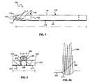
- FIG. 1is a side schematic view of an illumination display, consistent with an embodiment of the present invention.
- FIG. 2is an end schematic view of an illumination display, consistent with another embodiment of the present invention.
- FIG. 2Ais a side schematic view of light reflecting from a surface texture element in the illumination display of FIG. 2 .
- FIG. 3is a top plan view of an illumination display, consistent with a further embodiment of the present invention.
- FIG. 4is a bottom plan view of the illumination display shown in FIG. 3 .
- FIG. 5is an exploded side cross-sectional view of the illumination display taken along line 5 - 5 in FIG. 4 together with display panels.
- FIG. 6is an end cross-sectional view of a light transmitting panel in the illumination display taken along line 6 - 6 in FIG. 3 .
- FIG. 7is an exploded perspective view of an electronic chef's fork including an illumination display, consistent with a further embodiment of the present invention.
- FIG. 8is a side cross-sectional view of the illumination display in the electronic chef's fork shown in FIG. 7 .
- an illumination displayin general, includes a light transmitting panel that provides enhanced illumination edge lighting.
- One or more light sourcesare optically coupled into an edge of the light transmitting panel to illuminate the light transmitting panel.
- the light transmitting panelrefracts and reflects light such that a greater intensity of light may be emitted from one or more enhanced illumination portions, such as a raised enhanced illumination portion, of the light transmitting panel.
- the light source(s)may emit light of different colors corresponding to different conditions such that the illumination display indicates a condition by illuminating the light transmitting panel with the color corresponding to the condition.
- the illumination displaymay be used in various devices including, but not limited to, a device for checking the temperature of food.
- the term “coupled”may refer to mechanical, optical and/or electrical coupling and does not imply a direct coupling or connection unless otherwise specified.
- the term “optically coupled”refers to at least one coupled element being adapted to impart light to another coupled element directly or indirectly.
- “reflect”refers to the redirection of at least a portion of incident radiation and does not require reflection of all radiation nor does it require reflection at any particular angle.
- an illumination display 100generally includes a light transmitting panel 110 and one or more light sources 120 optically coupled to the light transmitting panel 110 .
- the light transmitting panel 110includes one or more light coupling regions 112 at one or more locations along an edge 114 between front and back sides 116 , 118 of the light transmitting panel 110 .
- the light source 120may be located at the light coupling portion 112 on the edge 114 such that the light emitted from the light source 120 is optically coupled into the light transmitting panel 110 via the edge 114 .
- the light source 120may be oriented at about 90° relative to the light transmitting panel 110 .
- the light coupled into the light transmitting panel 110may be refracted and/or reflected internally to illuminate the light transmitting panel 110 .
- the edge 114has a thickness t that is less than a length l of the sides of the light transmitting panel 110 , the light coupled into the edge 114 is dispersed along a smaller surface area and experiences less scattering, for example, as compared to coupling light into the back side 116 .
- the light source 120is shown in the exemplary embodiment as directly coupling light into the light coupling region 112 , other optical elements, such as lenses and/or optical coupling materials, may also be located between the light source 120 and the light coupling region 112 .
- the light source 120is a light emitting diode (LED) such as the type used to provide backlighting for a liquid crystal display (LCD) panel.
- the light source(s) 120may be configured to emit light of different colors, for example, in response to a condition such as a detected condition.
- the illumination display 100may display information by displaying different colors of light indicating different conditions, as will be described in greater detail below.
- the illumination display 100may also include one or more display panels (not shown), such as LCD panels, for displaying information and the light transmitting panel 110 provides backlighting for the display panels and/or enhances illumination of the text on the display panels.
- the illuminated display 100may also include other types of light sources including, but not limited to, an electro-luminescent panel.
- the light transmitting panel 110includes one or more enhanced illumination portions 130 on the front side 118 , for example, proximate the light coupling region 112 . At least a portion of the light coupled into the light transmitting panel 110 , as shown schematically by arrows 102 , is directed to the enhanced illumination portion 130 and is emitted from the enhanced illumination portion 130 .
- the light transmitting panel 110may act as a lens or prismatic element that changes the direction and intensity of the light by bending or refracting the light rays such that a higher concentration of light is focused on the enhanced illumination portion 130 .
- the light transmitting panel 110may further include a reflective material 140 on the back side 116 to facilitate reflection of the light within the light transmitting panel 110 .
- a reflective materialmay also be disposed along the edge 114 (other than on the light coupling region 112 ) and/or on other portions of the light transmitting panel 110 that are not intended to emit light. Reflective materials known to those skilled in the art for use in optical applications may be used.
- a light transmitting panel 210may include a raised enhanced illumination portion 230 extending from a front side, for example, proximate the light coupling region 212 . At least a portion of the light coupled into the light transmitting panel 210 , as shown schematically by arrows 202 , is directed into the raised enhanced illumination portion 230 and is emitted from a top illumination surface 232 of the raised enhanced illumination portion 230 . Light may also be emitted from a side surface 234 of the raised enhanced illumination portion 230 , for example, to further illuminate text on a display panel as described below.
- the light transmitting panel 210may act as a lens or prismatic element that changes the direction and intensity of the light by bending or refracting the light rays such that a higher concentration of light is focused in the raised enhanced illumination portion 230 .
- the raised enhanced illumination portion 230may thus act as a light pipe that carries and emits the higher concentration of light.
- the light coupling region 212is shown below the raised enhanced illumination portion 230 , the light coupling region 212 may also include an edge of the raised enhanced illumination portion 230 such that light is coupled directly into the raised enhanced illumination portion 230 .
- the width w 1 of the raised enhanced illumination portion 230may also be less than the width w and/or length l of the sides of the light transmitting panel 210 such that the light directed into the raised enhanced illumination portion 230 is concentrated on a smaller surface area (i.e., the illumination surface 232 ) and does not disperse as much, for example, as compared to the surface of the front side 218 .
- the intensity of the light emitted from the illumination surface 232 of the raised illumination portion 230may be greater than an intensity of the light emitted from other portions of the light transmitting panel 210 (e.g., from the front side 218 ).
- the light from the enhanced illumination portion 230is brighter and provides a higher contrast, which prevents it from being washed out or saturated by sunlight or other bright lighting.
- the raised enhanced illumination portion 230may have various sizes, shapes and orientations relative to the light transmitting panel 210 .
- the light transmitting panel 210may also include surface texturing 217 on the back side 216 to increase the surface area and help refract more light, making the illumination more consistent (e.g., across the front side 218 ).
- One example of the surface texturing 217may include a series or array of convex elements, as shown in greater detail in FIG. 2A .
- the light source 220may be positioned such that the surface texturing 217 (e.g., the convex elements) is in the line of site of the light source 220 , thus refracting light as indicated schematically by arrows 202 .
- the convex shapemay also focus the internally reflected light, as indicated schematically by arrows 204 .
- the surface texturing 217is shown as a series or array of convex elements, elements of other shapes, sizes and numbers may also be used to provide the surface texturing 217 that increases the surface area.
- the elements of the surface texturing 217may also be concave depressions that increase the surface area and help to refract the light more consistently.
- a combination of convex and concave elements (or other types of surface texturing elements)may also be used.
- the back side 216may be a smooth surface with no surface texturing.
- a reflective material 240may be provided over the surface texturing 217 .
- the illuminate display 300includes a light transmitting panel 310 and light sources 320 , 322 , such as LEDs, coupling light into an edge of the light transmitting panel 310 at each end.
- the light transmitting panel 310includes recesses 313 , 315 that receive the light sources 320 , 322 .
- the illumination display 300may also include other numbers of light sources in other locations around the edge of the light transmitting panel 310 .
- the light transmitting panel 310includes a raised enhanced illumination portion 330 extending from the panel 310 proximate one of the light sources 320 .
- the raised enhanced illumination portion 330forms at least a partial border around a subsection of the light transmitting panel 310 (e.g., three sides of a rectangular shape).
- the light transmitting panel 310may direct light into the raised enhanced illumination portion 330 , for example, as described above.
- Other shapes and configurations of raised enhanced illumination portionsmay also be used.
- a raised enhanced illumination portionmay also extend around a portion of or the entire perimeter of a light transmitting panel.
- the light transmitting panel 310may also include surface texturing 317 , such as an array of convex elements, over at least a portion of a back side 316 and in the line of site of the light source 320 , as discussed above.
- the light transmitting panel 310may be recessed on the back side 316 such that the surface texturing 117 is in the line of site of the light source 320 .
- the surface texturing 117helps to refract the light and provide more consistent illumination.
- the surface texturing 117also appears as illuminated “dots” in the raised enhanced illuminated portion 330 .
- the surface texturingmay also have other shapes and configurations and may be located along other sides or regions of the light transmitting panel.
- the light transmitting panel 310includes display panel receiving regions 318 a , 318 b configured to receive display panels 350 , 352 , such as LCD panels ( FIG. 5 ).
- the light transmitting panel 310provides backlighting to the display panels 350 , 352 in the regions 318 a , 318 b .
- the raised enhanced illumination portion 330extends above the regions 318 a , 318 b and provides a frame or border around at least a portion of one of the display panels 350 .
- the raised enhanced illumination portion 330thus provides an illumination surface 332 that is not covered by the display panels 350 , 352 and emits the light directly (and with a higher contrast) without being impeded by the display panels 350 , 352 .
- the raised enhanced illumination portion 330may also enhance illumination of the text displayed on the display panel 350 .
- the light transmitting panel 310may be made of transparent materials known to those skilled in the art.
- the materialmay include a polycarbonate, acrylic, acrylonitrile butadiene styrene (ABS), or other suitable material used for lenses or light transmitting elements.
- the transparent materialmay have an index of refraction, for example, in a range of about 1.4 to 1.6.
- the light transmitting panel 310may be generally rectangular shaped, although the light transmitting panel 310 may also have other shapes, for example, depending upon the shapes of the LCD panel(s). The dimensions of the light transmitting panel 310 generally depend on the size of the apparatus and display in which it is used.
- an illumination display 700may be used in an electronic chef's fork 702 , consistent with a further embodiment.
- the electronic chef's fork 702generally includes a handle portion 760 coupled to a piercing element 762 .
- the handle portion 760may include a body portion 764 that acts as a display mounting portion and holds the illumination display 700 .
- the handle portion 760may also include front and back cover portions 770 , 772 secured over the body portion 764 .
- the piercing element 762may be secured between the front cover 770 and the body portion 764 .
- a window 774may be positioned over the illumination display 700 and received within an opening 776 in the front cover 770 such that the illumination display may be visible on the handle portion 760 .
- One or more temperature sensorsmay be thermally coupled to the piercing element 762 to sense a temperature of an item (e.g., a food item) contacting the piercing element 762 . Temperature sensors may be located, for example, in the tips 763 of the piercing element 762 .
- the chef's fork 702may also include an electronic control circuit 780 , such as one or more circuit boards, coupled to the temperature sensor and/or to the illumination display 700 .
- the electronic circuit 780may control the illumination display 700 in response to the sensed temperatures, for example, by causing the illumination display to change colors and display temperature and/or cooking information.
- the illumination display 700may include a light transmitting panel 710 with a raised enhanced illumination portion 730 and a LED 720 at each end of the transmitting panel 710 (only one LED is shown in FIG. 8 ).
- the LEDs 720are capable of emitting light of different colors, and the light is coupled into the light transmitting panel 710 and emitted from the raised enhanced illumination portion 730 .
- the electronic circuit 780may be coupled to the LEDs 720 to cause the LEDs to emit different colors of light in response to different sensed temperatures.
- the LCD panels 750 , 752may be received in the light transmitting panel 710 such that the light transmitting panel 710 also provides backlighting to the LCD panels 350 , 352 .
- the electronic circuit 780may be coupled to the LCD panels 750 , 752 to cause the LCD panels 750 , 752 to display information such as temperature, a type of food, and a level of “doneness” for the type of food.
- the raised enhanced illumination portion 730may also provide additional illumination of the text displayed on the display panel 750 to make the text easier to read.
- an illumination displayexamples include a chef's fork, an illumination display, consistent with the embodiments described herein, may also be used in other devices to enhance visibility in sunlight or other types of bright lighting (e.g., a bright fluorescent light).
- an illumination displaymay be used in other cooking thermometer devices and in tire pressure gauge devices such as the type disclosed in U.S. Pat. No. 7,013,722, which is fully incorporated herein by reference.
- the enhanced illumination edge lighting provided by the illumination displayfacilitates visibility of the color changing backlight in devices that use different color light to provide information.
- an illumination displayincludes a light transmitting panel having sides and an edge.
- the edge of the panelincludes at least one light coupling portion and at least one of the sides includes at least one enhanced illumination portion.
- the illumination displayfurther includes at least one light source optically coupled into the light coupling portion of the edge of the light transmitting panel.
- the light transmitting panelis configured to refract and reflect the coupled light such that an intensity of the light emitted from the at least one enhanced illumination portion is greater than an intensity of the light emitted from other portions of the light transmitting panel.
- an apparatus for determining food temperatureincludes a piercing element, a temperature sensor thermally coupled to the piercing element and configured to sense a temperature of an item contacting the piercing element, and a handle portion coupled to the piercing element.
- the apparatusalso includes an illumination display integral with the handle portion.
- the illumination displayincludes a light transmitting panel having sides and an edge. The edge of the panel includes at least one light coupling portion and at least one of the sides includes at least one enhanced illumination portion.
- the illumination displayfurther includes at least one light source optically coupled into the light coupling portion of the edge of the light transmitting panel.
- the light transmitting panelis configured to refract and reflect the coupled light such that an intensity of the light emitted from the at least one enhanced illumination portion is greater than an intensity of the light emitted from other portions of the light transmitting panel.
- the at least one light sourceis configured to emit light of different colors in response to a level of the temperature sensed by the temperature sensor.
- an apparatusincludes a display mounting portion and an illumination display mounted in the display mounting portion.
- the illumination displayincludes a light transmitting panel having sides and an edge.
- the edge of the panelincludes at least one light coupling portion and at least one of the sides includes at least one enhanced illumination portion.
- the illumination displayfurther includes at least one light source optically coupled into the light coupling portion of the edge of the light transmitting panel.
- the light transmitting panelis configured to refract and reflect the coupled light such that an intensity of the light emitted from the at least one enhanced illumination portion is greater than an intensity of the light emitted from other portions of the light transmitting panel.
- the at least one light sourceis configured to emit light of different colors representing information.
Landscapes
- Physics & Mathematics (AREA)
- General Physics & Mathematics (AREA)
- Optics & Photonics (AREA)
- Planar Illumination Modules (AREA)
- Illuminated Signs And Luminous Advertising (AREA)
Abstract
Description
Claims (16)
Priority Applications (1)
| Application Number | Priority Date | Filing Date | Title |
|---|---|---|---|
| US12/151,383US7889290B2 (en) | 2008-05-05 | 2008-05-05 | Illumination display with enhanced illumination edge lighting |
Applications Claiming Priority (1)
| Application Number | Priority Date | Filing Date | Title |
|---|---|---|---|
| US12/151,383US7889290B2 (en) | 2008-05-05 | 2008-05-05 | Illumination display with enhanced illumination edge lighting |
Publications (2)
| Publication Number | Publication Date |
|---|---|
| US20090273730A1 US20090273730A1 (en) | 2009-11-05 |
| US7889290B2true US7889290B2 (en) | 2011-02-15 |
Family
ID=41256859
Family Applications (1)
| Application Number | Title | Priority Date | Filing Date |
|---|---|---|---|
| US12/151,383Expired - Fee RelatedUS7889290B2 (en) | 2008-05-05 | 2008-05-05 | Illumination display with enhanced illumination edge lighting |
Country Status (1)
| Country | Link |
|---|---|
| US (1) | US7889290B2 (en) |
Cited By (25)
| Publication number | Priority date | Publication date | Assignee | Title |
|---|---|---|---|---|
| US20110221896A1 (en)* | 2010-02-28 | 2011-09-15 | Osterhout Group, Inc. | Displayed content digital stabilization |
| US8188880B1 (en)* | 2011-03-14 | 2012-05-29 | Google Inc. | Methods and devices for augmenting a field of view |
| US8467133B2 (en) | 2010-02-28 | 2013-06-18 | Osterhout Group, Inc. | See-through display with an optical assembly including a wedge-shaped illumination system |
| US8472120B2 (en) | 2010-02-28 | 2013-06-25 | Osterhout Group, Inc. | See-through near-eye display glasses with a small scale image source |
| US8477425B2 (en) | 2010-02-28 | 2013-07-02 | Osterhout Group, Inc. | See-through near-eye display glasses including a partially reflective, partially transmitting optical element |
| US8482859B2 (en) | 2010-02-28 | 2013-07-09 | Osterhout Group, Inc. | See-through near-eye display glasses wherein image light is transmitted to and reflected from an optically flat film |
| US8488246B2 (en) | 2010-02-28 | 2013-07-16 | Osterhout Group, Inc. | See-through near-eye display glasses including a curved polarizing film in the image source, a partially reflective, partially transmitting optical element and an optically flat film |
| US9091851B2 (en) | 2010-02-28 | 2015-07-28 | Microsoft Technology Licensing, Llc | Light control in head mounted displays |
| US9097890B2 (en) | 2010-02-28 | 2015-08-04 | Microsoft Technology Licensing, Llc | Grating in a light transmissive illumination system for see-through near-eye display glasses |
| US9097891B2 (en) | 2010-02-28 | 2015-08-04 | Microsoft Technology Licensing, Llc | See-through near-eye display glasses including an auto-brightness control for the display brightness based on the brightness in the environment |
| US9128281B2 (en) | 2010-09-14 | 2015-09-08 | Microsoft Technology Licensing, Llc | Eyepiece with uniformly illuminated reflective display |
| US9129295B2 (en) | 2010-02-28 | 2015-09-08 | Microsoft Technology Licensing, Llc | See-through near-eye display glasses with a fast response photochromic film system for quick transition from dark to clear |
| US9134534B2 (en) | 2010-02-28 | 2015-09-15 | Microsoft Technology Licensing, Llc | See-through near-eye display glasses including a modular image source |
| US9182596B2 (en) | 2010-02-28 | 2015-11-10 | Microsoft Technology Licensing, Llc | See-through near-eye display glasses with the optical assembly including absorptive polarizers or anti-reflective coatings to reduce stray light |
| US9223134B2 (en) | 2010-02-28 | 2015-12-29 | Microsoft Technology Licensing, Llc | Optical imperfections in a light transmissive illumination system for see-through near-eye display glasses |
| US9229227B2 (en) | 2010-02-28 | 2016-01-05 | Microsoft Technology Licensing, Llc | See-through near-eye display glasses with a light transmissive wedge shaped illumination system |
| US9285589B2 (en) | 2010-02-28 | 2016-03-15 | Microsoft Technology Licensing, Llc | AR glasses with event and sensor triggered control of AR eyepiece applications |
| US9341843B2 (en) | 2010-02-28 | 2016-05-17 | Microsoft Technology Licensing, Llc | See-through near-eye display glasses with a small scale image source |
| US9366862B2 (en) | 2010-02-28 | 2016-06-14 | Microsoft Technology Licensing, Llc | System and method for delivering content to a group of see-through near eye display eyepieces |
| US9759917B2 (en) | 2010-02-28 | 2017-09-12 | Microsoft Technology Licensing, Llc | AR glasses with event and sensor triggered AR eyepiece interface to external devices |
| US10018765B2 (en) | 2014-05-16 | 2018-07-10 | Corning Incorporated | Edge lighted backlight unit for liquid crystal display device |
| US10180572B2 (en) | 2010-02-28 | 2019-01-15 | Microsoft Technology Licensing, Llc | AR glasses with event and user action control of external applications |
| US10539787B2 (en) | 2010-02-28 | 2020-01-21 | Microsoft Technology Licensing, Llc | Head-worn adaptive display |
| US10807526B2 (en) | 2019-02-14 | 2020-10-20 | Volvo Car Corporation | Vehicle interior lighting system |
| US10860100B2 (en) | 2010-02-28 | 2020-12-08 | Microsoft Technology Licensing, Llc | AR glasses with predictive control of external device based on event input |
Families Citing this family (5)
| Publication number | Priority date | Publication date | Assignee | Title |
|---|---|---|---|---|
| JP5638371B2 (en)* | 2010-02-19 | 2014-12-10 | 三菱電機株式会社 | Planar light source device and display device |
| US9360196B2 (en) | 2012-06-15 | 2016-06-07 | Rtc Industries, Inc. | Low voltage power supply for a merchandise display system |
| US9225131B2 (en) | 2012-06-15 | 2015-12-29 | RTC Industries, Incorporated | Low voltage power supply with magnetic connections |
| US9146029B2 (en) | 2012-06-15 | 2015-09-29 | RTC Industries, Incorporated | Power supply with mechanical connections |
| WO2019147943A1 (en) | 2018-01-26 | 2019-08-01 | Rtc Industries, Inc. | Low voltage power system for a merchandise display |
Citations (5)
| Publication number | Priority date | Publication date | Assignee | Title |
|---|---|---|---|---|
| US4914553A (en)* | 1984-07-26 | 1990-04-03 | Sharp Kabushiki Kaisha | Lighting device |
| US5838405A (en)* | 1995-03-31 | 1998-11-17 | Sharp Kabushiki Kaisha | Tiled display device |
| US20070067118A1 (en)* | 2005-09-19 | 2007-03-22 | Cooper Kerry J | Rechargeable food thermometer |
| US20090015756A1 (en)* | 2007-07-10 | 2009-01-15 | Au Optronics Corp. | Color-filterless liquid crystal display device |
| US20090279020A1 (en)* | 2006-06-01 | 2009-11-12 | Sharp Kabushiki Kaisha | Surface-area light source device and liquid crystal display device using the same |
- 2008
- 2008-05-05USUS12/151,383patent/US7889290B2/ennot_activeExpired - Fee Related
Patent Citations (5)
| Publication number | Priority date | Publication date | Assignee | Title |
|---|---|---|---|---|
| US4914553A (en)* | 1984-07-26 | 1990-04-03 | Sharp Kabushiki Kaisha | Lighting device |
| US5838405A (en)* | 1995-03-31 | 1998-11-17 | Sharp Kabushiki Kaisha | Tiled display device |
| US20070067118A1 (en)* | 2005-09-19 | 2007-03-22 | Cooper Kerry J | Rechargeable food thermometer |
| US20090279020A1 (en)* | 2006-06-01 | 2009-11-12 | Sharp Kabushiki Kaisha | Surface-area light source device and liquid crystal display device using the same |
| US20090015756A1 (en)* | 2007-07-10 | 2009-01-15 | Au Optronics Corp. | Color-filterless liquid crystal display device |
Cited By (31)
| Publication number | Priority date | Publication date | Assignee | Title |
|---|---|---|---|---|
| US9129295B2 (en) | 2010-02-28 | 2015-09-08 | Microsoft Technology Licensing, Llc | See-through near-eye display glasses with a fast response photochromic film system for quick transition from dark to clear |
| US9182596B2 (en) | 2010-02-28 | 2015-11-10 | Microsoft Technology Licensing, Llc | See-through near-eye display glasses with the optical assembly including absorptive polarizers or anti-reflective coatings to reduce stray light |
| US10860100B2 (en) | 2010-02-28 | 2020-12-08 | Microsoft Technology Licensing, Llc | AR glasses with predictive control of external device based on event input |
| US10539787B2 (en) | 2010-02-28 | 2020-01-21 | Microsoft Technology Licensing, Llc | Head-worn adaptive display |
| US8467133B2 (en) | 2010-02-28 | 2013-06-18 | Osterhout Group, Inc. | See-through display with an optical assembly including a wedge-shaped illumination system |
| US8472120B2 (en) | 2010-02-28 | 2013-06-25 | Osterhout Group, Inc. | See-through near-eye display glasses with a small scale image source |
| US8477425B2 (en) | 2010-02-28 | 2013-07-02 | Osterhout Group, Inc. | See-through near-eye display glasses including a partially reflective, partially transmitting optical element |
| US8482859B2 (en) | 2010-02-28 | 2013-07-09 | Osterhout Group, Inc. | See-through near-eye display glasses wherein image light is transmitted to and reflected from an optically flat film |
| US8488246B2 (en) | 2010-02-28 | 2013-07-16 | Osterhout Group, Inc. | See-through near-eye display glasses including a curved polarizing film in the image source, a partially reflective, partially transmitting optical element and an optically flat film |
| US8814691B2 (en) | 2010-02-28 | 2014-08-26 | Microsoft Corporation | System and method for social networking gaming with an augmented reality |
| US9091851B2 (en) | 2010-02-28 | 2015-07-28 | Microsoft Technology Licensing, Llc | Light control in head mounted displays |
| US9097890B2 (en) | 2010-02-28 | 2015-08-04 | Microsoft Technology Licensing, Llc | Grating in a light transmissive illumination system for see-through near-eye display glasses |
| US9097891B2 (en) | 2010-02-28 | 2015-08-04 | Microsoft Technology Licensing, Llc | See-through near-eye display glasses including an auto-brightness control for the display brightness based on the brightness in the environment |
| US10268888B2 (en) | 2010-02-28 | 2019-04-23 | Microsoft Technology Licensing, Llc | Method and apparatus for biometric data capture |
| US20110221668A1 (en)* | 2010-02-28 | 2011-09-15 | Osterhout Group, Inc. | Partial virtual keyboard obstruction removal in an augmented reality eyepiece |
| US20110221896A1 (en)* | 2010-02-28 | 2011-09-15 | Osterhout Group, Inc. | Displayed content digital stabilization |
| US9229227B2 (en) | 2010-02-28 | 2016-01-05 | Microsoft Technology Licensing, Llc | See-through near-eye display glasses with a light transmissive wedge shaped illumination system |
| US9223134B2 (en) | 2010-02-28 | 2015-12-29 | Microsoft Technology Licensing, Llc | Optical imperfections in a light transmissive illumination system for see-through near-eye display glasses |
| US9134534B2 (en) | 2010-02-28 | 2015-09-15 | Microsoft Technology Licensing, Llc | See-through near-eye display glasses including a modular image source |
| US9285589B2 (en) | 2010-02-28 | 2016-03-15 | Microsoft Technology Licensing, Llc | AR glasses with event and sensor triggered control of AR eyepiece applications |
| US9329689B2 (en) | 2010-02-28 | 2016-05-03 | Microsoft Technology Licensing, Llc | Method and apparatus for biometric data capture |
| US9341843B2 (en) | 2010-02-28 | 2016-05-17 | Microsoft Technology Licensing, Llc | See-through near-eye display glasses with a small scale image source |
| US9366862B2 (en) | 2010-02-28 | 2016-06-14 | Microsoft Technology Licensing, Llc | System and method for delivering content to a group of see-through near eye display eyepieces |
| US9759917B2 (en) | 2010-02-28 | 2017-09-12 | Microsoft Technology Licensing, Llc | AR glasses with event and sensor triggered AR eyepiece interface to external devices |
| US9875406B2 (en) | 2010-02-28 | 2018-01-23 | Microsoft Technology Licensing, Llc | Adjustable extension for temple arm |
| US10180572B2 (en) | 2010-02-28 | 2019-01-15 | Microsoft Technology Licensing, Llc | AR glasses with event and user action control of external applications |
| US9128281B2 (en) | 2010-09-14 | 2015-09-08 | Microsoft Technology Licensing, Llc | Eyepiece with uniformly illuminated reflective display |
| US8462010B2 (en) | 2011-03-14 | 2013-06-11 | Google Inc. | Methods and devices for augmenting a field of view |
| US8188880B1 (en)* | 2011-03-14 | 2012-05-29 | Google Inc. | Methods and devices for augmenting a field of view |
| US10018765B2 (en) | 2014-05-16 | 2018-07-10 | Corning Incorporated | Edge lighted backlight unit for liquid crystal display device |
| US10807526B2 (en) | 2019-02-14 | 2020-10-20 | Volvo Car Corporation | Vehicle interior lighting system |
Also Published As
| Publication number | Publication date |
|---|---|
| US20090273730A1 (en) | 2009-11-05 |
Similar Documents
| Publication | Publication Date | Title |
|---|---|---|
| US7889290B2 (en) | Illumination display with enhanced illumination edge lighting | |
| US11092847B2 (en) | Backlight module and display device | |
| US20040093779A1 (en) | Illuminated background display apparatus | |
| EP1913434B1 (en) | Illumination system, use of a light-sensing plate in an illumination system and display device | |
| KR20110103140A (en) | Multi-touch and proximity object sensing device for selectively irradiating light | |
| US20090303695A1 (en) | Display Element for an Electric Appliance | |
| TWI470169B (en) | Light module | |
| JP2009295318A (en) | Lighting system and electro-optical device | |
| KR20120120697A (en) | Apparatus for sensing multi touch and proximated object and display apparatus | |
| JP2006054088A (en) | Surface light-emitting device and liquid crystal display device | |
| US20080266272A1 (en) | Luminous touch sensor | |
| KR101318747B1 (en) | Backlight unit and liquid crystal display having the same | |
| CN102054607B (en) | Backlight key | |
| JP2000259347A5 (en) | Electronics | |
| KR101291233B1 (en) | Knob switch for lighting | |
| KR100941280B1 (en) | Display | |
| JPH09230338A (en) | Illuminating device | |
| US7703970B2 (en) | Illuminated background display apparatus | |
| KR20090098328A (en) | Light emitting diode illumination device and liquid crystal display device having the same | |
| CN101133356A (en) | Color identification of text or symbols in a monochrome liquid crystal display | |
| JP4975604B2 (en) | Self-lighting sign structure | |
| KR101519137B1 (en) | Light unit and liquid crystal display device having the same | |
| KR100803331B1 (en) | Outsole for liquid crystal display with reflective configuration with front light | |
| JP3559969B2 (en) | Light guide plate and reflective liquid crystal display | |
| US20140347571A1 (en) | Low profile backlight apparatus for high-brightness microdisplays |
Legal Events
| Date | Code | Title | Description |
|---|---|---|---|
| AS | Assignment | Owner name:BROOKSTONE PURCHASING, INC., NEW HAMPSHIRE Free format text:ASSIGNMENT OF ASSIGNORS INTEREST;ASSIGNOR:MILLS, STEPHEN B.;REEL/FRAME:020966/0794 Effective date:20080505 | |
| AS | Assignment | Owner name:BANK OF AMERICA, N.A., AS COLLATERAL AGENT,MASSACH Free format text:SECURITY AGREEMENT;ASSIGNORS:BROOKSTONE COMPANY, INC.;BROOKSTONE INTERNATIONAL HOLDINGS, INC.;BROOKSTONE HOLDINGS, INC.;AND OTHERS;REEL/FRAME:024320/0649 Effective date:20100416 Owner name:BANK OF AMERICA, N.A., AS COLLATERAL AGENT, MASSAC Free format text:SECURITY AGREEMENT;ASSIGNORS:BROOKSTONE COMPANY, INC.;BROOKSTONE INTERNATIONAL HOLDINGS, INC.;BROOKSTONE HOLDINGS, INC.;AND OTHERS;REEL/FRAME:024320/0649 Effective date:20100416 | |
| AS | Assignment | Owner name:WELLS FARGO BANK, N.A., AS COLLATERAL AGENT, NEW Y Free format text:SECURITY AGREEMENT;ASSIGNORS:BROOKSTONE, INC.;BROOKSTONE COMPANY, INC.;BROOKSTONE INTERNATIONAL HOLDINGS, INC.;AND OTHERS;REEL/FRAME:025326/0911 Effective date:20101026 | |
| STCF | Information on status: patent grant | Free format text:PATENTED CASE | |
| AS | Assignment | Owner name:WELLS FARGO BANK, NATIONAL ASSOCIATION, MASSACHUSE Free format text:SECURITY AGREEMENT;ASSIGNORS:BROOKSTONE, INC.;BROOKSTONE COMPANY, INC.;BROOKSTONE INTERNATIONAL HOLDINGS, INC.;AND OTHERS;REEL/FRAME:027463/0537 Effective date:20111230 | |
| AS | Assignment | Owner name:BROOKSTONE MILITARY SALES, INC., NEW HAMPSHIRE Free format text:RELEASE BY SECURED PARTY;ASSIGNOR:BANK OF AMERICA, N.A.;REEL/FRAME:027468/0495 Effective date:20111230 Owner name:BROOKSTONE PURCHASING, INC., NEW HAMPSHIRE Free format text:RELEASE BY SECURED PARTY;ASSIGNOR:BANK OF AMERICA, N.A.;REEL/FRAME:027468/0495 Effective date:20111230 Owner name:BROOKSTONE INTERNATIONAL HOLDINGS, INC., NEW HAMPS Free format text:RELEASE BY SECURED PARTY;ASSIGNOR:BANK OF AMERICA, N.A.;REEL/FRAME:027468/0495 Effective date:20111230 Owner name:BNM, LLC, NEW HAMPSHIRE Free format text:RELEASE BY SECURED PARTY;ASSIGNOR:BANK OF AMERICA, N.A.;REEL/FRAME:027468/0495 Effective date:20111230 Owner name:ADVANCED AUDIO CONCEPTS, LTD., NEW HAMPSHIRE Free format text:RELEASE BY SECURED PARTY;ASSIGNOR:BANK OF AMERICA, N.A.;REEL/FRAME:027468/0495 Effective date:20111230 Owner name:BROOKSTONE HOLDINGS, INC., NEW HAMPSHIRE Free format text:RELEASE BY SECURED PARTY;ASSIGNOR:BANK OF AMERICA, N.A.;REEL/FRAME:027468/0495 Effective date:20111230 Owner name:GARDENERS EDEN INC., NEW HAMPSHIRE Free format text:RELEASE BY SECURED PARTY;ASSIGNOR:BANK OF AMERICA, N.A.;REEL/FRAME:027468/0495 Effective date:20111230 Owner name:BROOKSTONE PUERTO RICO, INC., NEW HAMPSHIRE Free format text:RELEASE BY SECURED PARTY;ASSIGNOR:BANK OF AMERICA, N.A.;REEL/FRAME:027468/0495 Effective date:20111230 Owner name:BROOKSTONE COMPANY, INC., NEW HAMPSHIRE Free format text:RELEASE BY SECURED PARTY;ASSIGNOR:BANK OF AMERICA, N.A.;REEL/FRAME:027468/0495 Effective date:20111230 Owner name:BROOKSTONE STORES, INC., NEW HAMPSHIRE Free format text:RELEASE BY SECURED PARTY;ASSIGNOR:BANK OF AMERICA, N.A.;REEL/FRAME:027468/0495 Effective date:20111230 Owner name:BROOKSTONE PROPERTIES, INC., NEW HAMPSHIRE Free format text:RELEASE BY SECURED PARTY;ASSIGNOR:BANK OF AMERICA, N.A.;REEL/FRAME:027468/0495 Effective date:20111230 Owner name:BIG BLUE AUDIO, LLC, NEW HAMPSHIRE Free format text:RELEASE BY SECURED PARTY;ASSIGNOR:BANK OF AMERICA, N.A.;REEL/FRAME:027468/0495 Effective date:20111230 Owner name:BROOKSTONE, INC., NEW HAMPSHIRE Free format text:RELEASE BY SECURED PARTY;ASSIGNOR:BANK OF AMERICA, N.A.;REEL/FRAME:027468/0495 Effective date:20111230 | |
| AS | Assignment | Owner name:BROOKSTONE INTERNATIONAL HOLDINGS, INC., NEW HAMPS Free format text:RELEASE OF SECURITY INTEREST;ASSIGNOR:WELLS FARGO BANK;REEL/FRAME:033282/0721 Effective date:20140707 Owner name:BIG BLUE AUDIO LLC, NEW HAMPSHIRE Free format text:RELEASE OF SECURITY INTEREST;ASSIGNOR:WELLS FARGO BANK;REEL/FRAME:033282/0721 Effective date:20140707 Owner name:BROOKSTONE MILITARY SALES, INC., NEW HAMPSHIRE Free format text:RELEASE OF SECURITY INTEREST;ASSIGNOR:WELLS FARGO BANK;REEL/FRAME:033282/0721 Effective date:20140707 Owner name:BROOKSTONE PUERTO RICO, INC., NEW HAMPSHIRE Free format text:RELEASE OF SECURITY INTEREST;ASSIGNOR:WELLS FARGO BANK;REEL/FRAME:033282/0721 Effective date:20140707 Owner name:BROOKSTONE PROPERTIES, INC., NEW HAMPSHIRE Free format text:RELEASE OF SECURITY INTEREST;ASSIGNOR:WELLS FARGO BANK;REEL/FRAME:033282/0721 Effective date:20140707 Owner name:BROOKSTONE STORES, INC., NEW HAMPSHIRE Free format text:RELEASE OF SECURITY INTEREST;ASSIGNOR:WELLS FARGO BANK;REEL/FRAME:033282/0721 Effective date:20140707 Owner name:BROOKSTONE HOLDINGS, INC., NEW HAMPSHIRE Free format text:RELEASE OF SECURITY INTEREST;ASSIGNOR:WELLS FARGO BANK;REEL/FRAME:033282/0721 Effective date:20140707 Owner name:BROOKSTONE PURCHASING, INC., NEW HAMPSHIRE Free format text:RELEASE OF SECURITY INTEREST;ASSIGNOR:WELLS FARGO BANK;REEL/FRAME:033282/0721 Effective date:20140707 Owner name:BNM, LLC, NEW HAMPSHIRE Free format text:RELEASE OF SECURITY INTEREST;ASSIGNOR:WELLS FARGO BANK;REEL/FRAME:033282/0721 Effective date:20140707 Owner name:GENERAL ELECTRIC CAPITAL CORPORATION, ILLINOIS Free format text:SECURITY INTEREST;ASSIGNORS:BIG BLUE AUDIO LLC;BROOKSTONE COMPANY, INC.;BROOKSTONE PURCHASING, INC.;REEL/FRAME:033282/0664 Effective date:20140707 Owner name:BROOKSTONE, INC., NEW HAMPSHIRE Free format text:RELEASE OF SECURITY INTEREST;ASSIGNOR:WELLS FARGO BANK;REEL/FRAME:033282/0721 Effective date:20140707 Owner name:BROOKSTONE COMPANY, INC., NEW HAMPSHIRE Free format text:RELEASE OF SECURITY INTEREST;ASSIGNOR:WELLS FARGO BANK;REEL/FRAME:033282/0721 Effective date:20140707 Owner name:GARDENERS EDEN, INC., NEW HAMPSHIRE Free format text:RELEASE OF SECURITY INTEREST;ASSIGNOR:WELLS FARGO BANK;REEL/FRAME:033282/0721 Effective date:20140707 | |
| FPAY | Fee payment | Year of fee payment:4 | |
| AS | Assignment | Owner name:WELLS FARGO BANK, NATIONAL ASSOCIATION, MASSACHUSE Free format text:ASSIGNMENT OF SECURITY AGREEMENT FOR PATENTS;ASSIGNOR:GENERAL ELECTRIC CAPITAL CORPORATION;REEL/FRAME:039669/0205 Effective date:20160301 | |
| MAFP | Maintenance fee payment | Free format text:PAYMENT OF MAINTENANCE FEE, 8TH YEAR, LARGE ENTITY (ORIGINAL EVENT CODE: M1552) Year of fee payment:8 | |
| AS | Assignment | Owner name:SANPOWER (HONG KONG) COMPANY LIMITED, CHINA Free format text:SECURITY INTEREST;ASSIGNORS:BROOKSTONE COMPANY, INC.;BROOKSTONE PURCHASING, INC.;BIG BLUE AUDIO LLC;REEL/FRAME:046539/0357 Effective date:20180706 | |
| AS | Assignment | Owner name:WELLS FARGO BANK, NATIONAL ASSOCIATION, AS AGENT, Free format text:PATENT SECURITY AGREEMENT;ASSIGNORS:BIG BLUE AUDIO LLC;BROOKSTONE COMPANY, INC.;BROOKSTONE PURCHASING, INC.;REEL/FRAME:047570/0677 Effective date:20180829 | |
| AS | Assignment | Owner name:BIG BLUE AUDIO, LLC, NEW HAMPSHIRE Free format text:TERMINATION AND RELEASE OF SECURITY INTEREST IN PATENTS RECORDED AT REEL 33282/FRAME 664, REEL 36992/FRAME 599, REEL 37333/FRAME 878, AND REEL 39669/FRAME 0205;ASSIGNOR:WELLS FARGO BANK, NATIONAL ASSOCIATION;REEL/FRAME:047296/0766 Effective date:20181019 Owner name:BROOKSTONE COMPANY, INC., NEW HAMPSHIRE Free format text:TERMINATION AND RELEASE OF SECURITY INTEREST IN PATENTS RECORDED AT REEL 33282/FRAME 664, REEL 36992/FRAME 599, REEL 37333/FRAME 878, AND REEL 39669/FRAME 0205;ASSIGNOR:WELLS FARGO BANK, NATIONAL ASSOCIATION;REEL/FRAME:047296/0766 Effective date:20181019 Owner name:BROOKSTONE PURCHASING, INC., NEW HAMPSHIRE Free format text:TERMINATION AND RELEASE OF SECURITY INTEREST IN PATENTS RECORDED AT REEL 33282/FRAME 664, REEL 36992/FRAME 599, REEL 37333/FRAME 878, AND REEL 39669/FRAME 0205;ASSIGNOR:WELLS FARGO BANK, NATIONAL ASSOCIATION;REEL/FRAME:047296/0766 Effective date:20181019 | |
| AS | Assignment | Owner name:BROOKSTONE COMPANY, INC., NEW HAMPSHIRE Free format text:TERMINATION AND RELEASE OF SECUIRTY INTEREST IN INTELLECTUAL PROPERTY RECORDED AT REEL 046539/FRAME 0357;ASSIGNOR:SANPOWER (HONG KONG) COMPANY LIMITED;REEL/FRAME:047597/0847 Effective date:20181019 Owner name:BROOKSTONE PURCHASING, INC., NEW HAMPSHIRE Free format text:TERMINATION AND RELEASE OF SECUIRTY INTEREST IN INTELLECTUAL PROPERTY RECORDED AT REEL 046539/FRAME 0357;ASSIGNOR:SANPOWER (HONG KONG) COMPANY LIMITED;REEL/FRAME:047597/0847 Effective date:20181019 Owner name:BIG BLUE AUDIO, LLC, NEW HAMPSHIRE Free format text:TERMINATION AND RELEASE OF SECUIRTY INTEREST IN INTELLECTUAL PROPERTY RECORDED AT REEL 046539/FRAME 0357;ASSIGNOR:SANPOWER (HONG KONG) COMPANY LIMITED;REEL/FRAME:047597/0847 Effective date:20181019 | |
| FEPP | Fee payment procedure | Free format text:MAINTENANCE FEE REMINDER MAILED (ORIGINAL EVENT CODE: REM.); ENTITY STATUS OF PATENT OWNER: LARGE ENTITY | |
| LAPS | Lapse for failure to pay maintenance fees | Free format text:PATENT EXPIRED FOR FAILURE TO PAY MAINTENANCE FEES (ORIGINAL EVENT CODE: EXP.); ENTITY STATUS OF PATENT OWNER: LARGE ENTITY | |
| STCH | Information on status: patent discontinuation | Free format text:PATENT EXPIRED DUE TO NONPAYMENT OF MAINTENANCE FEES UNDER 37 CFR 1.362 | |
| FP | Lapsed due to failure to pay maintenance fee | Effective date:20230215 |