US7889097B1 - Detecting targets in roadway intersections - Google Patents
Detecting targets in roadway intersectionsDownload PDFInfo
- Publication number
- US7889097B1 US7889097B1US11/614,250US61425006AUS7889097B1US 7889097 B1US7889097 B1US 7889097B1US 61425006 AUS61425006 AUS 61425006AUS 7889097 B1US7889097 B1US 7889097B1
- Authority
- US
- United States
- Prior art keywords
- transducer
- signal
- sensor
- electronically steered
- traffic sensor
- Prior art date
- Legal status (The legal status is an assumption and is not a legal conclusion. Google has not performed a legal analysis and makes no representation as to the accuracy of the status listed.)
- Active, expires
Links
Images


Classifications
- G—PHYSICS
- G08—SIGNALLING
- G08G—TRAFFIC CONTROL SYSTEMS
- G08G1/00—Traffic control systems for road vehicles
- G08G1/01—Detecting movement of traffic to be counted or controlled
- G08G1/04—Detecting movement of traffic to be counted or controlled using optical or ultrasonic detectors
- G—PHYSICS
- G01—MEASURING; TESTING
- G01S—RADIO DIRECTION-FINDING; RADIO NAVIGATION; DETERMINING DISTANCE OR VELOCITY BY USE OF RADIO WAVES; LOCATING OR PRESENCE-DETECTING BY USE OF THE REFLECTION OR RERADIATION OF RADIO WAVES; ANALOGOUS ARRANGEMENTS USING OTHER WAVES
- G01S13/00—Systems using the reflection or reradiation of radio waves, e.g. radar systems; Analogous systems using reflection or reradiation of waves whose nature or wavelength is irrelevant or unspecified
- G01S13/02—Systems using reflection of radio waves, e.g. primary radar systems; Analogous systems
- G01S13/06—Systems determining position data of a target
- G01S13/42—Simultaneous measurement of distance and other co-ordinates
- G—PHYSICS
- G01—MEASURING; TESTING
- G01S—RADIO DIRECTION-FINDING; RADIO NAVIGATION; DETERMINING DISTANCE OR VELOCITY BY USE OF RADIO WAVES; LOCATING OR PRESENCE-DETECTING BY USE OF THE REFLECTION OR RERADIATION OF RADIO WAVES; ANALOGOUS ARRANGEMENTS USING OTHER WAVES
- G01S13/00—Systems using the reflection or reradiation of radio waves, e.g. radar systems; Analogous systems using reflection or reradiation of waves whose nature or wavelength is irrelevant or unspecified
- G01S13/88—Radar or analogous systems specially adapted for specific applications
- G01S13/91—Radar or analogous systems specially adapted for specific applications for traffic control
- G01S13/92—Radar or analogous systems specially adapted for specific applications for traffic control for velocity measurement
- H—ELECTRICITY
- H01—ELECTRIC ELEMENTS
- H01Q—ANTENNAS, i.e. RADIO AERIALS
- H01Q3/00—Arrangements for changing or varying the orientation or the shape of the directional pattern of the waves radiated from an antenna or antenna system
- H01Q3/26—Arrangements for changing or varying the orientation or the shape of the directional pattern of the waves radiated from an antenna or antenna system varying the relative phase or relative amplitude of energisation between two or more active radiating elements; varying the distribution of energy across a radiating aperture
- G—PHYSICS
- G01—MEASURING; TESTING
- G01S—RADIO DIRECTION-FINDING; RADIO NAVIGATION; DETERMINING DISTANCE OR VELOCITY BY USE OF RADIO WAVES; LOCATING OR PRESENCE-DETECTING BY USE OF THE REFLECTION OR RERADIATION OF RADIO WAVES; ANALOGOUS ARRANGEMENTS USING OTHER WAVES
- G01S13/00—Systems using the reflection or reradiation of radio waves, e.g. radar systems; Analogous systems using reflection or reradiation of waves whose nature or wavelength is irrelevant or unspecified
- G01S13/02—Systems using reflection of radio waves, e.g. primary radar systems; Analogous systems
- G01S2013/0236—Special technical features
- G01S2013/0245—Radar with phased array antenna
- G01S2013/0254—Active array antenna
- G—PHYSICS
- G01—MEASURING; TESTING
- G01S—RADIO DIRECTION-FINDING; RADIO NAVIGATION; DETERMINING DISTANCE OR VELOCITY BY USE OF RADIO WAVES; LOCATING OR PRESENCE-DETECTING BY USE OF THE REFLECTION OR RERADIATION OF RADIO WAVES; ANALOGOUS ARRANGEMENTS USING OTHER WAVES
- G01S7/00—Details of systems according to groups G01S13/00, G01S15/00, G01S17/00
- G01S7/003—Transmission of data between radar, sonar or lidar systems and remote stations
Definitions
- the present inventionrelates to detecting targets in roadway intersections.
- traffic sensorsfor the actuation of traffic signal lights located at the intersection of roadways is quite common.
- traffic sensorscan provide input used to properly actuate traffic control devices in response to the detection or lack of detection of vehicles.
- traffic sensorscan enable a traffic control device to skip unnecessary signal phases, such as, for example, skipping a left hand turn phase when no vehicles are detected in a corresponding left hand turn lane.
- Traffic sensorscan also enable a traffic signal to increase green light duration for major arterials by only signaling the green light in the minor cross streets when vehicles are detected on the minor cross streets and thus minimizing the red light for a major arterial.
- traffic sensorsassist in properly actuating a signalized intersection to improve traffic flow.
- traffic sensorsare also used for the actuation of intersections of a roadway for automobile traffic with a railway.
- Inductive loop detectorsare very expensive to install since lane closures are necessary. The high cost is compounded, especially for multi-lane roadways, since at least one inductive loop detector is required for each detection zone (e.g., left hand turn lane detection zones, through lane detection zones, and right hand turn lane detection zones). Furthermore, inductive loop detector technology is often unreliable and inductive loop detectors require a great deal of calibration.
- Video detectorsare also used in some traffic signal actuation systems.
- a video camerais placed high above a signal arm such that the video camera's view covers one approach to the intersection.
- the video signal from the camerais digitally processed to create detections in the defined zones.
- an intersectioncan be monitored on a per approach basis (that is all the lanes of an approach), as opposed to the per detection zone basis used with inductive loops.
- at least one camera per approachis required. Since a dedicated mounting arm is often necessary and at least one camera per approach is required, the installation of a video detector system can also be expensive and time consuming.
- Microwave detectorshave also been used in intersections to provide detection coverage over limited areas. At least one microwave detector has a limited degree of mechanical and electrical steering. However, similar to video detectors, one microwave detector per approach is required and the coverage is typically over a small portion of the intersection. Further, manual configuration is needed to ensure that the proper detection zones from each sensor are wired to the proper input in the traffic controller.
- microwave sensorshave included multiple receive antennas but have included only a single transmit antenna that has a very broad main beam or even may be an omni-directional antenna.
- Systems that employ only one broad beam or omni-directional transmit antennatypically cannot achieve an appropriately reduced side lobe power level.
- these single transmit antenna systemstypically suffer from widening of the mainlobe.
- a traffic sensorincludes a transducer system and a transceiver system.
- the transducer systemcreates a plurality of transducer views of the roadway intersection. Each transducer view can detect targets located in a portion of the roadway intersection.
- the transducer systemincludes a transducer configured to transmit signals towards a portion of two or more approaches to the roadway intersection and configured to receive signals and signal reflections within the portions of the two or more approaches to the roadway intersection.
- the transceiver systemis configured to generate digital data indicative of the transducer receiving a signal or signal reflection.
- the transducer system and transceiver systeminteroperate to generate an aggregate sensor view of the roadway intersection.
- the aggregate sensor viewincludes a plurality of transducer views of the two or more approaches to the roadway intersection.
- the traffic sensoris configured to have an aggregate sensor view of approximately 270 degrees. In other embodiments, the traffic sensor is configured to have an aggregate view of approximately 90 degrees. In these other embodiments, multiple collocated sensors can be used together to provide larger aggregate views.
- FIG. 1illustrates one embodiment of an intersection traffic sensor
- FIG. 2depicts the example intersection vehicle traffic sensor of FIG. 1 in an intersection of roadways and depicts a further aggregate sensor view.
- FIG. 3depicts an example architecture for a switched antenna intersection traffic sensor.
- FIG. 4depicts an example architecture for an electronically steered antenna intersection traffic sensor.
- FIG. 5depicts an example architecture for a mechanically steered intersection traffic sensor.
- a traffic sensorincludes a transducer system and a transceiver system.
- the transducer systemcreates a plurality of transducer views of the roadway intersection. Each transducer view can detect targets located in a portion of the roadway intersection.
- the transducer systemincludes a transducer configured to transmit signals towards a portion of two or more approaches to the roadway intersection and configured to receive signals and signal reflections within the portions of the two or more approaches to the roadway intersection.
- the transceiver systemis configured to generate digital data indicative of the transducer receiving a signal or signal reflection.
- the transducer system and transceiver systeminteroperate to generate an aggregate sensor view of the roadway intersection.
- the aggregate sensor viewincludes a plurality of transducer views of the two or more approaches to the roadway intersection.
- the traffic sensoris configured to have an aggregate sensor view of approximately 270 degrees. In other embodiments, the traffic sensor is configured to have an aggregate view of approximately 90 degrees. In these other embodiments, multiple collocated sensors can be used together to provide larger aggregate views.
- transducermeans a device for converting signals that propagate through the air (e.g., radar signals, electromagnetic signals, acoustic signals, laser signals, infrared signals, etc.) into electronic signals in a traffic sensor
- the word “transducer”can also mean a device for converting electronic signals in a traffic sensor into signals that propagate through the air.
- a microwave antennais a transducer.
- intersection of roadwaysis defined as the intersection of two or more roadways for automobile and/or truck traffic including the approaches to the intersection.
- road intersectionis defined to include an intersection of roadways and also to include an intersection of roadways with one or more thoroughfares for other traffic, including the approaches to the intersection. Thoroughfares for other traffic may include pedestrian paths and railways.
- FIG. 1is an example intersection traffic sensor 20 .
- intersection traffic sensor 20can be used to detect objects (e.g., vehicles, pedestrians, etc.) at a roadway intersection.
- traffic sensor 20includes transducer system 10 , transceiver 12 , processor 14 , and storage 32 .
- Transceiver 12is configured to generate signals (e.g., signal 2 ) and receive back corresponding signal reflections (e.g., signal reflection 3 ) that result from generated signals reflecting off of an object, such as, for example, a vehicle. Transceiver 12 is also configured to receive signals (including any of previously described types of signals) from other sensors (e.g., signal 4 ).
- a generated transmit signalcan include a Frequency Modulated Continuous Wave (“FMCW”) radar signal that is generated via direct digital synthesis and frequency multiplication.
- a generated transmit signalcan also include one or more of a microwave transmit signal, an acoustic transmit signal, a laser transmit signal, a non-coherent light signal, and an infrared signal.
- Processor 14processes signals and signal reflections received by transceiver 12 (collectively referred to as sensor data, such as, for example, sensor data 29 ) to convert signals and signal reflections into meaningful digital data (e.g., digital data 6 ).
- sensor datasuch as, for example, sensor data 29
- meaningful digital datae.g., digital data 6
- Processor 14can be a digital signal processor configured to convert signals and signal reflections into digital data and deliver digital data to external components, such as, for example, communication link 33 (e.g., to a display device or another computer system), storage 37 (e.g., a magnetic disk, RAM, etc.), and contact closure 39 .
- communication link 33e.g., to a display device or another computer system
- storage 37e.g., a magnetic disk, RAM, etc.
- contact closure 39e.g., contact closure 39 .
- Digital data 6can include, for example, a sensor configuration, presence indications, vehicle detections, and traffic statistics.
- Traffic statisticscan include: vehicle counts per lane; vehicle counts per direction; vehicle counts per approach; turning counts; average speeds per lane, direction, or approach; 85th percentile speeds per lane, direction, or approach; occupancy per lane, direction, or approach; etc.
- Processor 14can also be configured to control transceiver 12 .
- processor 14can send signal activation command 5 to transceiver 12 when transceiver 12 is to generate a signal.
- Transducer system 10is configured to create areas (hereinafter referred to as “transducer views”) over which a transmit signal is propagated and/or from which a signal and/or signal reflection is received.
- transducer system 10creates multiple transducer views by switching between multiple fixed beam antennas, each one steered to a different angle.
- an electronically steerable antenna implemented using phase shiftersis used to electronically steer the antenna beam to different angles thus achieving the different transducer views.
- multiple transducer viewsare created using a single antenna that is connected to the transceiver 12 via a rotary joint. The antenna is rotated around an axis so that a different transducer view is available at each instant in time.
- Aggregate sensor viewmeans a view as observed by a sensor composed of a plurality of transducer views.
- transducer system 10creates an aggregate sensor view including transducer views 28 A- 28 G.
- a power level defining the edge of a transducer viewcan be configured based on the sensitivity of transceiver 12 and detection algorithms running on processor 14 .
- FIG. 2depicts the intersection traffic sensor 20 of FIG. 1 in an intersection of roadways 41 .
- Sensor 20utilizes multiple transducer views 24 A- 24 BB which, in combination, form the aggregate sensor view 24 .
- the extent of the aggregate sensor view 24is depicted as a rectangular. However, the extent of the aggregate sensor view 24 is actually defined by the limits of sensor 20 's capabilities and is not necessarily rectangular.
- Transducer system 10can be configured to switch (e.g., radar) signal transmission between transducer views 24 A- 24 BB on (transmitting and receiving a signal) and off (not transmitting nor receiving a signal) in sequence.
- Transceiver 12can receive a reflected signal (e.g., a radar return) from a range in each of the transducer views 24 A- 24 BB. The range is the distance between sensor 20 and the targets 26 A and 26 B.
- sensor 20can receive a radar return from multiple azimuth angles, which are measured in the horizontal plane.
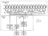
- FIG. 3depicts an example architecture 300 for a switched antenna intersection traffic sensor.
- architecture 300includes transceiver 12 A and transducer system 10 A.
- transceiver 12 Ais configured to receive signal activations, interoperate with transducer system 10 A, and send sensor data.
- transceiver 12 Acan receive signal activation 5 A (e.g., from a processor). Signal activation 5 A can be similar to signal activation 5 from FIG. 1 . Signal activation 5 A triggers the RF signal generation 60 A.
- the RF signal generation 60 Aincludes direct digital synthesis and frequency up-conversion. The resulting signal is a 6 GHz to 6.0625 GHz FMCW chirp.
- This signalis then routed to one of sixteen quadruplers (e.g., quadruplers 76 A- 76 P) via a 6 GHz switch (e.g., switch 71 ).
- a control linee.g., control line 77 A controls the 6 GHz switch (e.g., switch 71 ).
- the effect of the quadruplersis to quadruple the frequency of the signal resulting in a 24 GHz to 24.25 GHz chirp.
- the sixteen quadruplerscan be switched on (quadrupling the frequency of the input signal) and off (not quadrupling the frequency of the input signal and providing isolation of the input signal from the output).
- the quadruplersare followed by power amplifiers (e.g., amplifiers 72 A- 72 P). These sixteen amplifiers can also be switched on (amplifying) and off (not amplifying). By switching the quadruplers and the power amplifiers the isolation on the transmit signals can be improved and power consumption is reduced by only powering the devices as needed.
- Quadrupler and amplifier biasing(e.g., biasing 73 A- 73 P) is used to switch the quadruplers and amplifiers on and off.
- the biasingis created by quadrupler and amplifier bias generation (e.g., quadrupler and amplifier bias generation 70 ).
- the quadrupler and amplifier bias generationis controlled by the signal activation (e.g., signal activation 5 A).
- the signal activationcan dictate which of the quadrupler-amplifier pairs are switched on.
- the quadrupler-amplifier pair that is connected to the RF signal via the 6 GHz switchwill be switched on. The others will be switched off.
- Transmission line couplersare used to split the signal from the amplifiers (e.g., amplifiers 72 A- 72 P) so that a portion of the signal is delivered to the LO port of the mixers (e.g., mixers 74 A- 74 P) and a portion is delivered to the transmit antennas (e.g. antennas 78 A- 78 P) in transducers system 10 A.
- Embodiments of the present inventioncan include both directional transmit antennas and directional receive antennas.
- a plurality of transmit antennasmay be necessary to achieve multiple transducer views.
- Using a plurality of directional transmit antennasdecreases the sidelobe level in the two-way antenna patterns and narrows the main bean in the two-way antenna patterns.
- a directional antennacan have a mainlobe steered to a specific direction and will have sidelobes in other directions. In some antennas, these sidelobes will receive or transmit power at an approximate level of ⁇ 20 dB from the mainlobe.
- the combined sidelobe approximate levelis ⁇ 40 dB.
- This same approximate ⁇ 40 dB sidelobe levelcan be achieved if one antenna is used to both receive and transmit.
- the same effect that causes the reduced sidelobe level in the two-way antenna patternalso causes a narrowing of the mainlobe.
- the beamwidth of the mainlobeis narrower than if a single broad transmit antenna is used.
- the signal from the receive antennas (e.g., antennas 78 AA- 78 PP) in transducer system 10 Ais amplified by a low noise amplifier (e.g., amplifiers 79 A- 79 P).
- the amplified signalis delivered to the RF port of the mixers (e.g., mixers 74 A- 74 P).
- the intermediate frequency (IF) signalwhich in the case of FMCW demodulation is a baseband signal, is produced at the IF mixer ports.
- the IF signals from each of the mixers (e.g., mixers 74 A- 74 P)are fed into a baseband switch (e.g., baseband switch 80 ).
- the baseband switch control(e.g., switch control 77 B) is synchronized with the quadrupler and amplifier biases and the 6 GHz switch control (e.g., switch control 77 A) so that the appropriate baseband is connected to baseband amplification and filtering (e.g., baseband amplification and filtering 62 A).
- baseband amplification and filteringe.g., baseband amplification and filtering 62 A
- the signalis considered sensor data (e.g., sensor data 29 A).
- This sensor datais digitized and converted into useful information by a processor (e.g., processor 14 ).
- the transmit and receive antennasin transducer system 10 A are traveling wave series fed microstrip patch antennas that are terminated by a matched microstrip patch. Traveling wave series fed microstrip patch antennas create a fan shaped antenna beam.
- This type of antennais a printed microwave antenna that is manufactured using printed circuit board techniques.
- the antennascan be oriented so that the antenna beam is narrow in the azimuth (or horizontal) plane and wide in the elevation (or vertical) plane.
- the steer angle of the beamwhich is measured in the azimuth plane, may be dictated by the phasing between the antenna elements. The spacing of the elements at least in part controls this phasing.
- antenna 78 Acan be designed so that its beam is steered to near boresight (perpendicular).
- Antenna 78 Pcan be designed so that its beam is steered to approximately 42° off of boresight.
- sixteen (or some other appropriate number of) antennascan be designed with feed points on opposite sides so that the sixteen (or other appropriate number of) antenna beams cover a 90° area.
- One embodiment of the traffic sensorwill have an aggregate sensor view of 270°.
- three transceiver-transducer system pairssuch as the ones depicted in FIG. 3 are utilized.
- Each transceiver-transducer systemcan be oriented at 90° to the adjacent pair, resulting in an aggregate sensor view of 270°.
- the traffic sensorwill have an aggregate sensor view of 90°.
- multiple traffic sensorswill be used together to provide the needed detections.
- three sensorsmay be mounted on the same pole and oriented 90° from the adjacent sensor(s). In this orientation the aggregate sensor views of each of the sensors will then cover a 270° area.
- the processor or processors that control the three transceiver-transducer system pairswill create three signal activation signals (e.g., similar to signal activation 5 A) and will receive three sensor data signals (e.g., similar to sensor data 29 A).
- the same antennais used for transmitting and for receiving.
- a directional coupler or circulatorcan be used to separate the transmit signal from the receive signal.
- a two port mixercan be used in which the local oscillator (“LO”) signal and the radio frequency (“RF”) signals are injected into the same mixer port.
- the intermediate frequency (“IF”) signalwhich in the case of FMCW demodulation is a baseband signal, is produced at the other mixer port.
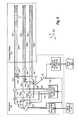
- FIG. 4depicts an example architecture 400 for an electronically steered antenna intersection traffic sensor.
- architecture 400includes transceiver 12 B and transducer system 10 B.
- transceiver 12 Bis configured to receive signal activations, interoperate with transducer system 10 B, and send sensor data.
- transceiver 12 Bcan receive signal activation 5 B (e.g., from a processor).
- Signal activation 5 Bcan be similar to signal activation 5 from FIG. 1 .
- Signal activation 5 Btriggers the RF signal generation 60 B.
- the RF signal generation 60 Bconsists of direct digital synthesis, a frequency up-conversion mixing stage, and a frequency multiplication stage.
- the resulting signalis a 24 GHz to 24.25 GHz FMCW chirp. This signal is amplified (as shown by example amplifier 66 B).
- a transmission line matched tee(e.g., tee 65 B) is used to split the signal so that a portion of the signal is delivered to the mixer (e.g., mixer 68 B) and a portion is delivered to the transducer system 10 B.
- the matched port of the matched teeis connected to the two port mixer (e.g., mixer 68 B).
- the transmit and receive signalsare separated using a directional coupler or a circulator and a standard three port mixer can be used. In still other embodiments, separate transmit and receive antennas are used.
- Amplification and filteringcan be performed on the baseband signal (as shown by the baseband amplification and filtering block 62 B) to generate the sensor data (e.g., sensor data 29 B).
- the sensor datacan then be digitized and converted into useful information by a processor (e.g., processor 14 ).
- the transducer system 10 Bincludes a corporate fed microstrip patch array antenna.
- the corporate feede.g., corporate feed 50
- the corporate feedserves to divide the power between the radiating patches (e.g., microstrip patches 54 A- 54 P) such that an amplitude window across the array is created. This amplitude window serves to reduce the antenna sidelobes.
- the strip line layer corporate feede.g., corporate feed 50
- Ferroelectric thin film passive phase shifterscan be utilized. Ferroelectric thin film passive phase shifters can be used to alter the phase of the signal that is radiated by each individual radiating element (e.g., microstrip patches 54 A- 54 P) or to alter the phase of the signal that is received by each individual radiating element.
- a phase shifter controle.g., phase shifter control 58
- phase shifter controlgenerates DC bias voltages that are transmitted by DC bias lines (e.g., DC bias lines 56 A- 56 P) and control the phase shifters (e.g., phase shifters 52 A- 52 P). This phase shifter control can generate the DC bias necessary for each phase shifter so that the beam that is generated from the antenna array is steered in the necessary direction.
- phase shifters based on time delayscan be used.
- the signal pathcan be switched between various delay line lengths. Each different delay line length will provide a different time delay and provide a different phase shift.
- a calibration processcan be utilized to eliminate phase errors introduced by variation between phase shifters and/or variation with temperature. This calibration process may be performed using an artificial tone that is injected into the antenna or using a bright target in the view of the sensor.
- the radiating elements (e.g., microstrip patches 54 A- 54 P) of transducer system 10 Bare located on the opposite side of the printed circuit board from the phase shifters (e.g., phase shifters 52 A- 52 P). Thus, unwanted radiation from the phase shifters can be mitigated.
- An electronically steered antennasuch as the one described above can be reasonably steered to approximately +45°.
- a preferred embodiment of the traffic sensorcan have an aggregate sensor view of 270°.
- three transceiver-transducer system pairssuch as the ones depicted in FIG. 4 can be utilized. Each transceiver-transducer system will be oriented at 90° to the adjacent pair. In this way, an aggregate sensor view of 270° can be achieved.
- the traffic sensorwill have an aggregate sensor view of 90°.
- multiple traffic sensorswill be used together to provide the needed detections.
- three sensorsmay be mounted on the same pole and oriented 90° from the adjacent sensor(s). In this orientation the aggregate sensor views of each of the sensors will then cover a 270° area.
- the processor that controls the three transceiver-transducer system pairswill create three signal activation signals (e.g., signal activation 5 B) and will receive three sensor data signals (e.g., sensor data 29 B).
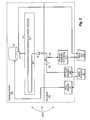
- FIG. 5depicts an example architecture 500 for a mechanically steered antenna intersection traffic sensor.
- architecture 500includes transceiver 12 C and transducer system 10 C.
- transceiver 12 Cis configured to receive signal activations, interoperate with transducer system 10 C, and send sensor data
- transceiver 12 Ccan receive signal activation 5 C (e.g., from a processor).
- Signal activation 5 Ccan be similar to signal activation 5 from FIG. 1 .
- Signal activation 5 Ctriggers the RF signal generation 60 C.
- the RF signal generation 60 Cconsists of direct digital synthesis, a frequency up-conversion mixing stage, and a frequency multiplication stage.
- the resulting signalis a 24 GHz to 24.25 GHz FMCW chirp. This signal is amplified (as shown by example amplifier 66 C).
- a transmission line matched tee(e.g., tee 65 C) is used to split the signal so that a portion of the signal is delivered to the mixer (e.g., mixer 68 C) and a portion is delivered to the transducer system (e.g. transducer system 10 C).
- the matched port of the matched teeis connected to the two port mixer (e.g., mixer 68 C).
- the transmit and receive signalsare separated using a directional coupler or a circulator and a standard three port mixer can be used. In still other embodiments, separate transmit and receive antennas are used.
- Amplification and filteringare performed on the baseband signal (as shown by the baseband amplification and filtering block 62 C) to generate the sensor data (e.g., sensor data 29 C) that can then be digitized and converted into useful information by a processor (e.g., processor 14 ).
- a processore.g., processor 14
- Embodiments of the transducer systeminclude a series fed microstrip patch array that is terminated in a matched microstrip patch (e.g., antenna 94 ).
- the arrayis phased so that the beam of the antenna is steered near boresight.
- the antennacan be printed onto a circuit board (e.g., circuit board 92 ) that spins by means of a magnetic bearing motor (e.g., motor 90 ).
- a magnetic bearing motoruses a magnetic field to suspend the motor shaft without physical contact. This type of motor is used in preferred embodiments in order to avoid the use of contact rotary bearings that would wear out and cause failure points.
- the motoris controlled by a control signal generated by a motor controller (e.g., motor controller 93 ).
- the motor controllerresponds to the signal activation signal (e.g., signal 5 C).
- a reflector or dielectric lensis rotated.
- a radiating sourceilluminates the reflector or dielectric lens, which becomes a rotating antenna.
- a rotary encoder(e.g., rotary encoder 91 ) can be included on the motor so that the angle information at each instant in time is available in the sensor data (e.g. sensor data 29 C).
- a contactless rotary joint(e.g., rotary joint 98 ) is used to provide signal connectivity between the stationary transceiver 12 C and the spinning antenna board 92 .
- a stripline transmission line 96transmits the RF signal from rotary joint to the antenna 94 .
- the use of a rotary jointallows for multiple 360° revolutions of the antenna (e.g., antenna 94 ).
- the motorspins at a constant rate while sensor data is continually created.
- sensor datais continually created.
Landscapes
- Engineering & Computer Science (AREA)
- Radar, Positioning & Navigation (AREA)
- Remote Sensing (AREA)
- Physics & Mathematics (AREA)
- General Physics & Mathematics (AREA)
- Computer Networks & Wireless Communication (AREA)
- Electromagnetism (AREA)
- Radar Systems Or Details Thereof (AREA)
Abstract
Description
Claims (28)
Priority Applications (9)
| Application Number | Priority Date | Filing Date | Title |
|---|---|---|---|
| US11/614,250US7889097B1 (en) | 2005-12-19 | 2006-12-21 | Detecting targets in roadway intersections |
| US12/502,965US8248272B2 (en) | 2005-10-31 | 2009-07-14 | Detecting targets in roadway intersections |
| US12/546,219US7889098B1 (en) | 2005-12-19 | 2009-08-24 | Detecting targets in roadway intersections |
| US12/546,196US7924170B1 (en) | 2005-12-19 | 2009-08-24 | Detecting targets in roadway intersections |
| US12/710,736US8665113B2 (en) | 2005-10-31 | 2010-02-23 | Detecting roadway targets across beams including filtering computed positions |
| US14/164,102US9240125B2 (en) | 2005-10-31 | 2014-01-24 | Detecting roadway targets across beams |
| US14/962,377US9601014B2 (en) | 2005-10-31 | 2015-12-08 | Detecting roadway targets across radar beams by creating a filtered comprehensive image |
| US15/187,508US10049569B2 (en) | 2005-10-31 | 2016-06-20 | Detecting roadway targets within a multiple beam radar system |
| US15/928,616US10276041B2 (en) | 2005-10-31 | 2018-03-22 | Detecting roadway targets across beams |
Applications Claiming Priority (2)
| Application Number | Priority Date | Filing Date | Title |
|---|---|---|---|
| US31110305A | 2005-12-19 | 2005-12-19 | |
| US11/614,250US7889097B1 (en) | 2005-12-19 | 2006-12-21 | Detecting targets in roadway intersections |
Related Parent Applications (3)
| Application Number | Title | Priority Date | Filing Date |
|---|---|---|---|
| US11/264,339Continuation-In-PartUS7573400B2 (en) | 2005-10-31 | 2005-10-31 | Systems and methods for configuring intersection detection zones |
| US31110305AContinuation | 2005-12-19 | 2005-12-19 | |
| US12/502,965Continuation-In-PartUS8248272B2 (en) | 2005-10-31 | 2009-07-14 | Detecting targets in roadway intersections |
Related Child Applications (4)
| Application Number | Title | Priority Date | Filing Date |
|---|---|---|---|
| US12/502,965Continuation-In-PartUS8248272B2 (en) | 2005-10-31 | 2009-07-14 | Detecting targets in roadway intersections |
| US12/546,219DivisionUS7889098B1 (en) | 2005-12-19 | 2009-08-24 | Detecting targets in roadway intersections |
| US12/546,196DivisionUS7924170B1 (en) | 2005-12-19 | 2009-08-24 | Detecting targets in roadway intersections |
| US12/710,736Continuation-In-PartUS8665113B2 (en) | 2005-10-31 | 2010-02-23 | Detecting roadway targets across beams including filtering computed positions |
Publications (1)
| Publication Number | Publication Date |
|---|---|
| US7889097B1true US7889097B1 (en) | 2011-02-15 |
Family
ID=43568572
Family Applications (3)
| Application Number | Title | Priority Date | Filing Date |
|---|---|---|---|
| US11/614,250Active2027-10-23US7889097B1 (en) | 2005-10-31 | 2006-12-21 | Detecting targets in roadway intersections |
| US12/546,219ActiveUS7889098B1 (en) | 2005-12-19 | 2009-08-24 | Detecting targets in roadway intersections |
| US12/546,196ActiveUS7924170B1 (en) | 2005-12-19 | 2009-08-24 | Detecting targets in roadway intersections |
Family Applications After (2)
| Application Number | Title | Priority Date | Filing Date |
|---|---|---|---|
| US12/546,219ActiveUS7889098B1 (en) | 2005-12-19 | 2009-08-24 | Detecting targets in roadway intersections |
| US12/546,196ActiveUS7924170B1 (en) | 2005-12-19 | 2009-08-24 | Detecting targets in roadway intersections |
Country Status (1)
| Country | Link |
|---|---|
| US (3) | US7889097B1 (en) |
Cited By (14)
| Publication number | Priority date | Publication date | Assignee | Title |
|---|---|---|---|---|
| US20130083649A1 (en)* | 2008-11-24 | 2013-04-04 | At&T Intellectual Property I, L.P. | Cell-to-wifi switcher |
| US8842182B2 (en) | 2009-12-22 | 2014-09-23 | Leddartech Inc. | Active 3D monitoring system for traffic detection |
| US8908159B2 (en) | 2011-05-11 | 2014-12-09 | Leddartech Inc. | Multiple-field-of-view scannerless optical rangefinder in high ambient background light |
| US9235988B2 (en) | 2012-03-02 | 2016-01-12 | Leddartech Inc. | System and method for multipurpose traffic detection and characterization |
| US9240125B2 (en) | 2005-10-31 | 2016-01-19 | Wavetronix Llc | Detecting roadway targets across beams |
| US9349288B2 (en) | 2014-07-28 | 2016-05-24 | Econolite Group, Inc. | Self-configuring traffic signal controller |
| US9378640B2 (en) | 2011-06-17 | 2016-06-28 | Leddartech Inc. | System and method for traffic side detection and characterization |
| US9412271B2 (en) | 2013-01-30 | 2016-08-09 | Wavetronix Llc | Traffic flow through an intersection by reducing platoon interference |
| US9574387B2 (en) | 2014-11-21 | 2017-02-21 | The Chamberlain Group, Inc. | Alignment of obstacle detection components |
| US20180267160A1 (en)* | 2017-03-20 | 2018-09-20 | David Slemp | Frequency Modulated Continuous Wave Antenna System |
| US10488492B2 (en) | 2014-09-09 | 2019-11-26 | Leddarttech Inc. | Discretization of detection zone |
| US10809354B2 (en)* | 2014-07-28 | 2020-10-20 | S.M.S. Smart Microwave Sensors Gmbh | Method for determining a position and/or orientation of a sensor |
| USRE48781E1 (en) | 2001-09-27 | 2021-10-19 | Wavetronix Llc | Vehicular traffic sensor |
| US11372096B2 (en)* | 2017-03-20 | 2022-06-28 | David Slemp | Frequency modulated continuous wave antenna system |
Families Citing this family (9)
| Publication number | Priority date | Publication date | Assignee | Title |
|---|---|---|---|---|
| DE102008054624A1 (en)* | 2008-12-15 | 2010-06-17 | Robert Bosch Gmbh | FMCW radar sensor for motor vehicles |
| US8386156B2 (en)* | 2010-08-02 | 2013-02-26 | Siemens Industry, Inc. | System and method for lane-specific vehicle detection and control |
| WO2012068064A1 (en)* | 2010-11-15 | 2012-05-24 | Image Sensing Systems, Inc. | Hybrid traffic sensor system and associated method |
| US9472097B2 (en)* | 2010-11-15 | 2016-10-18 | Image Sensing Systems, Inc. | Roadway sensing systems |
| US20130169468A1 (en)* | 2011-12-30 | 2013-07-04 | Flir Systems, Inc. | Radar system and related methods |
| US9618605B2 (en) | 2011-12-30 | 2017-04-11 | Flir Systems, Inc. | Radar system providing multiple waveforms for long range and short range target detection |
| JP2014048855A (en)* | 2012-08-31 | 2014-03-17 | Sumitomo Electric Ind Ltd | Traffic information measurement device and method for measuring traffic information |
| CN110874926A (en)* | 2018-08-31 | 2020-03-10 | 百度在线网络技术(北京)有限公司 | Intelligent road side unit |
| EP4113747A1 (en)* | 2020-11-17 | 2023-01-04 | Stichting IMEC Nederland | Beam steering antenna systems and methods thereof |
Citations (32)
| Publication number | Priority date | Publication date | Assignee | Title |
|---|---|---|---|---|
| GB1443701A (en) | 1972-07-17 | 1976-07-21 | Peak Technologies Ltd | Traffic signal systems |
| US4167330A (en) | 1977-07-08 | 1979-09-11 | Bei Electronics, Inc. | Velocity measuring system |
| US4908615A (en) | 1987-06-26 | 1990-03-13 | Texas Instruments Incorporated | Traffic light control system and method |
| US5339081A (en) | 1991-04-09 | 1994-08-16 | Peek Traffic Limited | Vehicle detection systems |
| US5663720A (en) | 1995-06-02 | 1997-09-02 | Weissman; Isaac | Method and system for regional traffic monitoring |
| US5721194A (en)* | 1992-12-01 | 1998-02-24 | Superconducting Core Technologies, Inc. | Tuneable microwave devices including fringe effect capacitor incorporating ferroelectric films |
| US5793491A (en) | 1992-12-30 | 1998-08-11 | Schwartz Electro-Optics, Inc. | Intelligent vehicle highway system multi-lane sensor and method |
| US5798983A (en) | 1997-05-22 | 1998-08-25 | Kuhn; John Patrick | Acoustic sensor system for vehicle detection and multi-lane highway monitoring |
| US5926114A (en) | 1998-05-18 | 1999-07-20 | Toyota Jidosha Kabushiki Kaisha | Intersection warning system |
| US6037894A (en) | 1995-07-01 | 2000-03-14 | Robert Bosch Gmbh | Monostatic FMCW radar sensor |
| US6114973A (en) | 1996-09-12 | 2000-09-05 | Robert Bosch Gmbh | Method and apparatus for recognizing whether traffic drives on the right or on the left |
| US6118405A (en)* | 1998-08-11 | 2000-09-12 | Nortel Networks Limited | Antenna arrangement |
| US6124807A (en) | 1992-04-02 | 2000-09-26 | Albert E. Voehringer | Process and apparatus for regulating traffic |
| US6490519B1 (en) | 1999-09-27 | 2002-12-03 | Decell, Inc. | Traffic monitoring system and methods for traffic monitoring and route guidance useful therewith |
| US6556916B2 (en) | 2001-09-27 | 2003-04-29 | Wavetronix Llc | System and method for identification of traffic lane positions |
| US6693557B2 (en) | 2001-09-27 | 2004-02-17 | Wavetronix Llc | Vehicular traffic sensor |
| US6781523B2 (en) | 2001-03-30 | 2004-08-24 | National Institute Of Information And Communications Technology | Road traffic monitoring system |
| US20050046597A1 (en) | 2003-08-18 | 2005-03-03 | Hutchison Michael C. | Traffic light signal system using radar-based target detection and tracking |
| US6888474B2 (en) | 2000-08-29 | 2005-05-03 | Optisoft, Inc. | System and method for configuring an electronically steerable beam of a traffic signal light |
| US20050231384A1 (en) | 2004-04-15 | 2005-10-20 | Denso Corporation | Vehicle information system for a loop intersection |
| US20050242306A1 (en) | 2004-04-29 | 2005-11-03 | Sirota J M | System and method for traffic monitoring, speed determination, and traffic light violation detection and recording |
| US7089422B2 (en) | 2002-06-28 | 2006-08-08 | Sony United Kingdom Limited | Embedding data in an information signal |
| US20060287807A1 (en) | 2003-05-19 | 2006-12-21 | Teffer Dean W | Method for incorporating individual vehicle data collection, detection and recording of traffic violations in a traffic signal controller |
| US20070096943A1 (en) | 2005-10-31 | 2007-05-03 | Arnold David V | Systems and methods for configuring intersection detection zones |
| US20070152869A1 (en) | 2005-12-30 | 2007-07-05 | Woodington Walter G | Multichannel processing of signals in a radar system |
| US20070208495A1 (en) | 2006-03-03 | 2007-09-06 | Chapman Craig H | Filtering road traffic condition data obtained from mobile data sources |
| US7317406B2 (en) | 2005-02-03 | 2008-01-08 | Toyota Technical Center Usa, Inc. | Infrastructure-based collision warning using artificial intelligence |
| US7327280B2 (en) | 2002-08-15 | 2008-02-05 | California Institute Of Technology | Emergency vehicle traffic signal preemption system |
| US7408479B2 (en) | 2003-08-19 | 2008-08-05 | Door-Man Manufacturing Company | Traffic detection and signal system and method therefor |
| US7421334B2 (en) | 2003-04-07 | 2008-09-02 | Zoom Information Systems | Centralized facility and intelligent on-board vehicle platform for collecting, analyzing and distributing information relating to transportation infrastructure and conditions |
| US7426450B2 (en) | 2003-01-10 | 2008-09-16 | Wavetronix, Llc | Systems and methods for monitoring speed |
| US7501976B2 (en) | 2006-11-07 | 2009-03-10 | Dan Manor | Monopulse traffic sensor and method |
Family Cites Families (1)
| Publication number | Priority date | Publication date | Assignee | Title |
|---|---|---|---|---|
| JP2000293099A (en) | 1999-04-09 | 2000-10-20 | Toyota Motor Corp | Map database |
- 2006
- 2006-12-21USUS11/614,250patent/US7889097B1/enactiveActive
- 2009
- 2009-08-24USUS12/546,219patent/US7889098B1/enactiveActive
- 2009-08-24USUS12/546,196patent/US7924170B1/enactiveActive
Patent Citations (34)
| Publication number | Priority date | Publication date | Assignee | Title |
|---|---|---|---|---|
| GB1443701A (en) | 1972-07-17 | 1976-07-21 | Peak Technologies Ltd | Traffic signal systems |
| US4167330A (en) | 1977-07-08 | 1979-09-11 | Bei Electronics, Inc. | Velocity measuring system |
| US4908615A (en) | 1987-06-26 | 1990-03-13 | Texas Instruments Incorporated | Traffic light control system and method |
| US5339081A (en) | 1991-04-09 | 1994-08-16 | Peek Traffic Limited | Vehicle detection systems |
| US6124807A (en) | 1992-04-02 | 2000-09-26 | Albert E. Voehringer | Process and apparatus for regulating traffic |
| US5721194A (en)* | 1992-12-01 | 1998-02-24 | Superconducting Core Technologies, Inc. | Tuneable microwave devices including fringe effect capacitor incorporating ferroelectric films |
| US5793491A (en) | 1992-12-30 | 1998-08-11 | Schwartz Electro-Optics, Inc. | Intelligent vehicle highway system multi-lane sensor and method |
| US5663720A (en) | 1995-06-02 | 1997-09-02 | Weissman; Isaac | Method and system for regional traffic monitoring |
| US6037894A (en) | 1995-07-01 | 2000-03-14 | Robert Bosch Gmbh | Monostatic FMCW radar sensor |
| US6114973A (en) | 1996-09-12 | 2000-09-05 | Robert Bosch Gmbh | Method and apparatus for recognizing whether traffic drives on the right or on the left |
| US5798983A (en) | 1997-05-22 | 1998-08-25 | Kuhn; John Patrick | Acoustic sensor system for vehicle detection and multi-lane highway monitoring |
| US5926114A (en) | 1998-05-18 | 1999-07-20 | Toyota Jidosha Kabushiki Kaisha | Intersection warning system |
| US6118405A (en)* | 1998-08-11 | 2000-09-12 | Nortel Networks Limited | Antenna arrangement |
| US6490519B1 (en) | 1999-09-27 | 2002-12-03 | Decell, Inc. | Traffic monitoring system and methods for traffic monitoring and route guidance useful therewith |
| US6888474B2 (en) | 2000-08-29 | 2005-05-03 | Optisoft, Inc. | System and method for configuring an electronically steerable beam of a traffic signal light |
| US6781523B2 (en) | 2001-03-30 | 2004-08-24 | National Institute Of Information And Communications Technology | Road traffic monitoring system |
| US6556916B2 (en) | 2001-09-27 | 2003-04-29 | Wavetronix Llc | System and method for identification of traffic lane positions |
| US6693557B2 (en) | 2001-09-27 | 2004-02-17 | Wavetronix Llc | Vehicular traffic sensor |
| US7427930B2 (en) | 2001-09-27 | 2008-09-23 | Wavetronix Llc | Vehicular traffic sensor |
| US7089422B2 (en) | 2002-06-28 | 2006-08-08 | Sony United Kingdom Limited | Embedding data in an information signal |
| US7327280B2 (en) | 2002-08-15 | 2008-02-05 | California Institute Of Technology | Emergency vehicle traffic signal preemption system |
| US7426450B2 (en) | 2003-01-10 | 2008-09-16 | Wavetronix, Llc | Systems and methods for monitoring speed |
| US7421334B2 (en) | 2003-04-07 | 2008-09-02 | Zoom Information Systems | Centralized facility and intelligent on-board vehicle platform for collecting, analyzing and distributing information relating to transportation infrastructure and conditions |
| US20060287807A1 (en) | 2003-05-19 | 2006-12-21 | Teffer Dean W | Method for incorporating individual vehicle data collection, detection and recording of traffic violations in a traffic signal controller |
| US20050046597A1 (en) | 2003-08-18 | 2005-03-03 | Hutchison Michael C. | Traffic light signal system using radar-based target detection and tracking |
| US7408479B2 (en) | 2003-08-19 | 2008-08-05 | Door-Man Manufacturing Company | Traffic detection and signal system and method therefor |
| US20050231384A1 (en) | 2004-04-15 | 2005-10-20 | Denso Corporation | Vehicle information system for a loop intersection |
| US20050242306A1 (en) | 2004-04-29 | 2005-11-03 | Sirota J M | System and method for traffic monitoring, speed determination, and traffic light violation detection and recording |
| US7317406B2 (en) | 2005-02-03 | 2008-01-08 | Toyota Technical Center Usa, Inc. | Infrastructure-based collision warning using artificial intelligence |
| US20070096943A1 (en) | 2005-10-31 | 2007-05-03 | Arnold David V | Systems and methods for configuring intersection detection zones |
| US7573400B2 (en) | 2005-10-31 | 2009-08-11 | Wavetronix, Llc | Systems and methods for configuring intersection detection zones |
| US20070152869A1 (en) | 2005-12-30 | 2007-07-05 | Woodington Walter G | Multichannel processing of signals in a radar system |
| US20070208495A1 (en) | 2006-03-03 | 2007-09-06 | Chapman Craig H | Filtering road traffic condition data obtained from mobile data sources |
| US7501976B2 (en) | 2006-11-07 | 2009-03-10 | Dan Manor | Monopulse traffic sensor and method |
Non-Patent Citations (29)
| Title |
|---|
| A 24 GHz ACC Radar Sensor, Smart Microwave Sensors GmbH, Feb. 28, 2005. |
| Cambridge Consultants; Technology at the crossroads: new radar sensor allows pedestrians and traffic to coexist; Feb. 24, 2004. |
| Computer Vision Algorithms for Intersection Monitoring; Harini Veeraraghavan, Osama Masoud, and Nikolaos P. Papanikolopoulous, Senior Member, IEEE IEEE Transactions on Intelligent Transportation Systems, vol. 4, No. 2, Jun. 2003. |
| Examination Report from Canadian Patent Application No. 2512689, dated Sep. 30, 2010. |
| Image Sensor for Measuring Volumes by Direction Atsushi Saito International Sales & Marketing Department Social Systems Solution & Service Business Company OMRON Corporation, Tokyo Japan ITS World Congress Oct. 2004 1 pg. |
| International Search Report and Written Opinion from PCT/US2007/064711, dated Sep. 4, 2008. |
| International Search Report and Written Opinion from PCT/US2010/037602 dated Aug. 6, 2010. |
| International Search Report for PCT/US2010/037596 dated Aug. 19, 2010. |
| Klotz et al., "An Automotive Short Range High Resolution Pulse Radar Network," Jan. 2002. |
| Office Action dated Jan. 8, 2010 from U.S. Appl. No. 11/689,441. |
| Red Light Hold Radar-based system prevents collisions from red light runners Optisoft The Intelligent Traffic Signal Platform 2 pgs. |
| SmarTek Acoustic Sensor-Version 1 (SAS-1) Installation and Setup Guide; Apr. 3, 2003. |
| The UMRR 24GHz Radar Sensor Family for Short and Medium Range Applications, Smart Microwave Sensors GmbH, Apr. 8, 2004. |
| Transportation Sensors Optional features for the OptiSoft ITS Platform Optisoft The Intelligent Traffic Signal Platform 1 pg. |
| Transportation Systems Millimeter Wave Radar Traffic Sensor AutoTrak Aug. 17, 2004 2 pgs. |
| Transportation Systems Railway Grade Crossing Sensor Aug. 17, 2004 1 pg. |
| U.S. Appl. No. 10/603,608, filed Jun. 26, 2003, Huntingdon et al. |
| U.S. Appl. No. 10/754,217, filed Jan. 8, 2004, Arnold et al. |
| U.S. Appl. No. 11/311,103, filed Dec. 19, 2005, Arnold et al. |
| U.S. Appl. No. 11/689,441, filed Mar. 21, 2007, Giles et al. |
| U.S. Appl. No. 12/502,965, filed Jul. 14, 2009, Arnold et al. |
| U.S. Appl. No. 12/546,196, filed Aug. 24, 2009, Arnold et al. |
| U.S. Appl. No. 12/546,219, filed Aug. 24, 2009, Arnold et al. |
| U.S. Appl. No. 12/710,736, filed Feb. 23, 2010, Arnold et al. |
| U.S. Appl. No. 60/439,109, filed Jan. 10, 2003, Arnold et al. |
| U.S. Appl. No. 60/785,964, filed Mar. 24, 2006, Giles et al. |
| U.S. Appl. No. 61/185,005, filed Jun. 8, 2009, Arnold et al. |
| UMRR: A 24GHz Medium Range Radar Platform, Smart Microwave Sensors GmbH, Jul. 25, 2003. |
| University Research in Support of the Department of Transportation Program on Remote Sensing Applications in Transportation (DTRS56-00-BAA-0004) Nov. 1999. |
Cited By (28)
| Publication number | Priority date | Publication date | Assignee | Title |
|---|---|---|---|---|
| USRE48781E1 (en) | 2001-09-27 | 2021-10-19 | Wavetronix Llc | Vehicular traffic sensor |
| US10049569B2 (en) | 2005-10-31 | 2018-08-14 | Wavetronix Llc | Detecting roadway targets within a multiple beam radar system |
| US9240125B2 (en) | 2005-10-31 | 2016-01-19 | Wavetronix Llc | Detecting roadway targets across beams |
| US10276041B2 (en) | 2005-10-31 | 2019-04-30 | Wavetronix Llc | Detecting roadway targets across beams |
| US9601014B2 (en) | 2005-10-31 | 2017-03-21 | Wavetronic Llc | Detecting roadway targets across radar beams by creating a filtered comprehensive image |
| US8737357B2 (en)* | 2008-11-24 | 2014-05-27 | At&T Intellectual Property I, L.P. | Cell-to-WiFi switcher |
| US20130083649A1 (en)* | 2008-11-24 | 2013-04-04 | At&T Intellectual Property I, L.P. | Cell-to-wifi switcher |
| US8842182B2 (en) | 2009-12-22 | 2014-09-23 | Leddartech Inc. | Active 3D monitoring system for traffic detection |
| US8908159B2 (en) | 2011-05-11 | 2014-12-09 | Leddartech Inc. | Multiple-field-of-view scannerless optical rangefinder in high ambient background light |
| USRE48763E1 (en) | 2011-05-11 | 2021-10-05 | Leddartech Inc. | Multiple-field-of-view scannerless optical rangefinder in high ambient background light |
| USRE47134E1 (en) | 2011-05-11 | 2018-11-20 | Leddartech Inc. | Multiple-field-of-view scannerless optical rangefinder in high ambient background light |
| US9378640B2 (en) | 2011-06-17 | 2016-06-28 | Leddartech Inc. | System and method for traffic side detection and characterization |
| US9235988B2 (en) | 2012-03-02 | 2016-01-12 | Leddartech Inc. | System and method for multipurpose traffic detection and characterization |
| USRE50261E1 (en) | 2012-03-02 | 2025-01-07 | Leddartech Inc. | System and method for multipurpose traffic detection and characterization |
| USRE48914E1 (en) | 2012-03-02 | 2022-02-01 | Leddartech Inc. | System and method for multipurpose traffic detection and characterization |
| US9412271B2 (en) | 2013-01-30 | 2016-08-09 | Wavetronix Llc | Traffic flow through an intersection by reducing platoon interference |
| US9978270B2 (en) | 2014-07-28 | 2018-05-22 | Econolite Group, Inc. | Self-configuring traffic signal controller |
| US10809354B2 (en)* | 2014-07-28 | 2020-10-20 | S.M.S. Smart Microwave Sensors Gmbh | Method for determining a position and/or orientation of a sensor |
| US10991243B2 (en) | 2014-07-28 | 2021-04-27 | Econolite Group, Inc. | Self-configuring traffic signal controller |
| US9349288B2 (en) | 2014-07-28 | 2016-05-24 | Econolite Group, Inc. | Self-configuring traffic signal controller |
| US10198943B2 (en) | 2014-07-28 | 2019-02-05 | Econolite Group, Inc. | Self-configuring traffic signal controller |
| US10488492B2 (en) | 2014-09-09 | 2019-11-26 | Leddarttech Inc. | Discretization of detection zone |
| US9574387B2 (en) | 2014-11-21 | 2017-02-21 | The Chamberlain Group, Inc. | Alignment of obstacle detection components |
| US10473775B2 (en)* | 2017-03-20 | 2019-11-12 | David Slemp | Frequency modulated continuous wave antenna system |
| US20200096625A1 (en)* | 2017-03-20 | 2020-03-26 | David Slemp | Frequency Modulated Continuous Wave Antenna System |
| US10754018B2 (en)* | 2017-03-20 | 2020-08-25 | David Slemp | Frequency modulated continuous wave antenna system |
| US11372096B2 (en)* | 2017-03-20 | 2022-06-28 | David Slemp | Frequency modulated continuous wave antenna system |
| US20180267160A1 (en)* | 2017-03-20 | 2018-09-20 | David Slemp | Frequency Modulated Continuous Wave Antenna System |
Also Published As
| Publication number | Publication date |
|---|---|
| US7924170B1 (en) | 2011-04-12 |
| US7889098B1 (en) | 2011-02-15 |
Similar Documents
| Publication | Publication Date | Title |
|---|---|---|
| US7889097B1 (en) | Detecting targets in roadway intersections | |
| US8248272B2 (en) | Detecting targets in roadway intersections | |
| Russell et al. | Millimeter-wave radar sensor for automotive intelligent cruise control (ICC) | |
| US20150268336A1 (en) | Antenna apparatus, radar apparatus and on-vehicle radar system | |
| EP1832895B1 (en) | Method of detecting movements around automatic doors | |
| US8487810B2 (en) | Integrated and configurable radar system | |
| JP5464152B2 (en) | In-vehicle radar system | |
| US9140787B2 (en) | Radar sensor for motor vehicles, especially LCA sensor | |
| CN108919271A (en) | A kind of millimetre-wave radar system | |
| JP2003248055A (en) | Monopulse radar system | |
| JP2006201013A (en) | Automotive radar | |
| US11515624B2 (en) | Integrated cavity backed slot array antenna system | |
| CN103097909A (en) | Multi-range radar system | |
| JP2000022410A (en) | Directional coupler, antenna device and transmission/ reception equipment | |
| US11349202B2 (en) | Antenna device and radar including the same | |
| JP3511329B2 (en) | Automotive radar equipment | |
| CN107580682A (en) | Radar sensor for motor vehicle | |
| JPH11231053A (en) | In-vehicle radar device | |
| JP4654803B2 (en) | Radar device for vehicle periphery monitoring | |
| TR199701318T1 (en) | Airport surface detection radar. | |
| Li et al. | REITS: Reflective surface for intelligent transportation systems | |
| US11539120B2 (en) | Range adaptable antenna system for autonomous vehicles | |
| JP2011112600A (en) | Detection device | |
| US9046603B2 (en) | Radar sensor for motor vehicles, in particular RCA sensor | |
| Honma et al. | Millimeter-wave radar technology for automotive application |
Legal Events
| Date | Code | Title | Description |
|---|---|---|---|
| STCF | Information on status: patent grant | Free format text:PATENTED CASE | |
| AS | Assignment | Owner name:DBSI LIQUIDATING TRUST, (SUCCESSOR IN INTEREST TO Free format text:SECURITY AGREEMENT;ASSIGNOR:WAVETRONIX LLC;REEL/FRAME:027024/0024 Effective date:20060101 | |
| FPAY | Fee payment | Year of fee payment:4 | |
| AS | Assignment | Owner name:DBSI LIQUIDATING TRUST, OREGON Free format text:SECURITY INTEREST;ASSIGNOR:WAVETRONIX LLC;REEL/FRAME:036932/0950 Effective date:20151028 | |
| AS | Assignment | Owner name:WAVETRONIX LLC, UTAH Free format text:RELEASE BY SECURED PARTY;ASSIGNOR:DBSI LIQUIDATING TRUST;REEL/FRAME:037510/0453 Effective date:20151028 | |
| AS | Assignment | Owner name:WAVETRONIX LLC, UTAH Free format text:NUNC PRO TUNC ASSIGNMENT;ASSIGNORS:ARNOLD, DAVID V.;JARRETT, BRYAN R.;JARVIS, DALE M.;AND OTHERS;SIGNING DATES FROM 20130816 TO 20151113;REEL/FRAME:038976/0466 | |
| AS | Assignment | Owner name:WAVETRONIX LLC, UTAH Free format text:SECURITY INTEREST;ASSIGNOR:DBSI LIQUIDATING TRUST;REEL/FRAME:041012/0129 Effective date:20161216 | |
| MAFP | Maintenance fee payment | Free format text:PAYMENT OF MAINTENANCE FEE, 8TH YEAR, LARGE ENTITY (ORIGINAL EVENT CODE: M1552) Year of fee payment:8 | |
| AS | Assignment | Owner name:ZIONS BANCORPORATION, N.A., UTAH Free format text:SECURITY INTEREST;ASSIGNORS:WAVETRONIX LLC;HOBBLE CREEK SQUARE LLC;WAVETRONIX DISC INC.;AND OTHERS;REEL/FRAME:047935/0934 Effective date:20190107 | |
| AS | Assignment | Owner name:ZIONS BANCORPORATION, N.A. DBA ZIONS FIRST NATIONAL BANK, UTAH Free format text:CORRECTIVE ASSIGNMENT TO CORRECT THE RECEIVING PARTY NAME PREVIOUSLY RECORDED AT REEL: 47935 FRAME: 934. ASSIGNOR(S) HEREBY CONFIRMS THE ASSIGNMENT;ASSIGNORS:WAVETRONIX LLC;HOBBLE CREEK SQUARE LLC;WAVETRONIX DISC INC.;AND OTHERS;REEL/FRAME:048072/0613 Effective date:20190107 Owner name:ZIONS BANCORPORATION, N.A. DBA ZIONS FIRST NATIONA Free format text:CORRECTIVE ASSIGNMENT TO CORRECT THE RECEIVING PARTY NAME PREVIOUSLY RECORDED AT REEL: 47935 FRAME: 934. ASSIGNOR(S) HEREBY CONFIRMS THE ASSIGNMENT;ASSIGNORS:WAVETRONIX LLC;HOBBLE CREEK SQUARE LLC;WAVETRONIX DISC INC.;AND OTHERS;REEL/FRAME:048072/0613 Effective date:20190107 | |
| MAFP | Maintenance fee payment | Free format text:PAYMENT OF MAINTENANCE FEE, 12TH YEAR, LARGE ENTITY (ORIGINAL EVENT CODE: M1553); ENTITY STATUS OF PATENT OWNER: LARGE ENTITY Year of fee payment:12 |