US7887757B2 - Method and apparatus for dispensing diagnostic test strips - Google Patents
Method and apparatus for dispensing diagnostic test stripsDownload PDFInfo
- Publication number
- US7887757B2 US7887757B2US11/430,178US43017806AUS7887757B2US 7887757 B2US7887757 B2US 7887757B2US 43017806 AUS43017806 AUS 43017806AUS 7887757 B2US7887757 B2US 7887757B2
- Authority
- US
- United States
- Prior art keywords
- test strips
- test strip
- roller
- test
- storage container
- Prior art date
- Legal status (The legal status is an assumption and is not a legal conclusion. Google has not performed a legal analysis and makes no representation as to the accuracy of the status listed.)
- Active - Reinstated, expires
Links
- 238000000034methodMethods0.000titledescription13
- 238000002405diagnostic procedureMethods0.000titledescription7
- 238000012360testing methodMethods0.000claimsabstractdescription295
- 238000003860storageMethods0.000claimsdescription177
- 230000007613environmental effectEffects0.000abstractdescription6
- 239000000356contaminantSubstances0.000abstractdescription4
- 239000003921oilSubstances0.000abstractdescription2
- 230000000284resting effectEffects0.000description32
- 239000002274desiccantSubstances0.000description4
- 229920000642polymerPolymers0.000description3
- WQZGKKKJIJFFOK-GASJEMHNSA-NGlucoseNatural productsOC[C@H]1OC(O)[C@H](O)[C@@H](O)[C@@H]1OWQZGKKKJIJFFOK-GASJEMHNSA-N0.000description2
- 239000013060biological fluidSubstances0.000description2
- 239000008280bloodSubstances0.000description2
- 210000004369bloodAnatomy0.000description2
- 238000010276constructionMethods0.000description2
- 206010012601diabetes mellitusDiseases0.000description2
- 210000003811fingerAnatomy0.000description2
- 239000008103glucoseSubstances0.000description2
- 238000004519manufacturing processMethods0.000description2
- 239000000463materialSubstances0.000description2
- 238000012986modificationMethods0.000description2
- 230000004048modificationEffects0.000description2
- 239000000126substanceSubstances0.000description2
- 238000003466weldingMethods0.000description2
- 239000000853adhesiveSubstances0.000description1
- 230000001070adhesive effectEffects0.000description1
- 239000012491analyteSubstances0.000description1
- 230000006835compressionEffects0.000description1
- 238000007906compressionMethods0.000description1
- 238000011109contaminationMethods0.000description1
- 239000000383hazardous chemicalSubstances0.000description1
- 230000001771impaired effectEffects0.000description1
- 238000009434installationMethods0.000description1
- 239000002184metalSubstances0.000description1
- 239000002991molded plasticSubstances0.000description1
- 238000004064recyclingMethods0.000description1
- 210000003813thumbAnatomy0.000description1
Images


Classifications
- G—PHYSICS
- G01—MEASURING; TESTING
- G01N—INVESTIGATING OR ANALYSING MATERIALS BY DETERMINING THEIR CHEMICAL OR PHYSICAL PROPERTIES
- G01N33/00—Investigating or analysing materials by specific methods not covered by groups G01N1/00 - G01N31/00
- G01N33/48—Biological material, e.g. blood, urine; Haemocytometers
- G01N33/483—Physical analysis of biological material
- G01N33/487—Physical analysis of biological material of liquid biological material
- G01N33/4875—Details of handling test elements, e.g. dispensing or storage, not specific to a particular test method
- G01N33/48757—Test elements dispensed from a stack
- B—PERFORMING OPERATIONS; TRANSPORTING
- B65—CONVEYING; PACKING; STORING; HANDLING THIN OR FILAMENTARY MATERIAL
- B65D—CONTAINERS FOR STORAGE OR TRANSPORT OF ARTICLES OR MATERIALS, e.g. BAGS, BARRELS, BOTTLES, BOXES, CANS, CARTONS, CRATES, DRUMS, JARS, TANKS, HOPPERS, FORWARDING CONTAINERS; ACCESSORIES, CLOSURES, OR FITTINGS THEREFOR; PACKAGING ELEMENTS; PACKAGES
- B65D83/00—Containers or packages with special means for dispensing contents
- B65D83/08—Containers or packages with special means for dispensing contents for dispensing thin flat articles in succession
- B65D83/0805—Containers or packages with special means for dispensing contents for dispensing thin flat articles in succession through an aperture in a wall
- B65D83/0811—Containers or packages with special means for dispensing contents for dispensing thin flat articles in succession through an aperture in a wall with means for assisting dispensing
- B65D83/0823—Containers or packages with special means for dispensing contents for dispensing thin flat articles in succession through an aperture in a wall with means for assisting dispensing the articles being pushed and slid through the aperture
- B65D83/0829—Containers or packages with special means for dispensing contents for dispensing thin flat articles in succession through an aperture in a wall with means for assisting dispensing the articles being pushed and slid through the aperture by means of an actuator
- B—PERFORMING OPERATIONS; TRANSPORTING
- B65—CONVEYING; PACKING; STORING; HANDLING THIN OR FILAMENTARY MATERIAL
- B65D—CONTAINERS FOR STORAGE OR TRANSPORT OF ARTICLES OR MATERIALS, e.g. BAGS, BARRELS, BOTTLES, BOXES, CANS, CARTONS, CRATES, DRUMS, JARS, TANKS, HOPPERS, FORWARDING CONTAINERS; ACCESSORIES, CLOSURES, OR FITTINGS THEREFOR; PACKAGING ELEMENTS; PACKAGES
- B65D83/00—Containers or packages with special means for dispensing contents
- B65D83/08—Containers or packages with special means for dispensing contents for dispensing thin flat articles in succession
- B65D83/0847—Containers or packages with special means for dispensing contents for dispensing thin flat articles in succession through an aperture at the junction of two walls
- B65D83/0852—Containers or packages with special means for dispensing contents for dispensing thin flat articles in succession through an aperture at the junction of two walls with means for assisting dispensing
- B65D83/0864—Containers or packages with special means for dispensing contents for dispensing thin flat articles in succession through an aperture at the junction of two walls with means for assisting dispensing the articles being pushed and slid through the aperture
- B65D83/087—Containers or packages with special means for dispensing contents for dispensing thin flat articles in succession through an aperture at the junction of two walls with means for assisting dispensing the articles being pushed and slid through the aperture by means of an actuator
- B—PERFORMING OPERATIONS; TRANSPORTING
- B65—CONVEYING; PACKING; STORING; HANDLING THIN OR FILAMENTARY MATERIAL
- B65H—HANDLING THIN OR FILAMENTARY MATERIAL, e.g. SHEETS, WEBS, CABLES
- B65H3/00—Separating articles from piles
- B65H3/24—Separating articles from piles by pushers engaging the edges of the articles
- G—PHYSICS
- G01—MEASURING; TESTING
- G01N—INVESTIGATING OR ANALYSING MATERIALS BY DETERMINING THEIR CHEMICAL OR PHYSICAL PROPERTIES
- G01N33/00—Investigating or analysing materials by specific methods not covered by groups G01N1/00 - G01N31/00
- G01N33/48—Biological material, e.g. blood, urine; Haemocytometers
- G01N33/483—Physical analysis of biological material
- G01N33/487—Physical analysis of biological material of liquid biological material
- G01N33/4875—Details of handling test elements, e.g. dispensing or storage, not specific to a particular test method
Definitions
- the present inventiongenerally relates to diagnostic test strips for testing biological fluids. More specifically, the present invention relates to an apparatus and method for storing and dispensing diagnostic test strips.
- Diagnostic test stripsare used to measure analyte concentrations in biological fluids. For example, diagnostic test strips are often used by diabetic patients to monitor blood glucose levels.
- test stripsTo preserve their integrity, diagnostic test strips must be maintained in appropriate environmental conditions. That is, the test strips should be maintained at appropriate humidity levels, and should remain free of foreign substances. Furthermore, to avoid contamination by oils or foreign substances, test strips should not be handled prior to use.
- test stripsare typically maintained in a storage vial or the like.
- a userIn order to use the test strip, a user must reach into the vial, and retrieve a single test strip.
- many userssuch as diabetic patients, have impaired vision or physical dexterity. Such users may find it difficult to retrieve a single test strip from a storage vial. Further, users may accidentally touch multiple test strips while reaching into the storage vial to withdraw a test strip, and potentially contaminate the unused test strips.
- An object of the present inventionis to address at least the above problems and/or disadvantages and to provide at least the advantages described below. Accordingly, an object of the present invention is to provide an apparatus for storing a plurality of test strips and for dispensing the test strips one at a time.
- an apparatus for storing and dispensing a test stripwhich comprises a container configured to store a stack of test strips, a roller disposed in the container, the roller adapted to contact one test strip of the stack of test strips, and an actuator for actuating the roller to dispense the one test strip from the container.
- an apparatus for storing and dispensing a test stripcomprises a container configured to store a stack of test strips, a lid connected to the container by a living hinge, and a linkage assembly operatively connected to the lid.
- the linkage assemblyis adapted to contact one test strip of the stack of test strips so that when the lid is opened, a test strip is dispensed.
- an apparatus for storing and dispensing test stripscomprises a container configured to store a stack of test strips, a spring disposed in the container, the spring adapted to contact one test strip of the stack of test strips, and an actuator for actuating the spring to dispense the one test strip from the container.
- an apparatus for storing and dispensing test stripscomprises means for storing a stack of test strips, means for contacting one test strip of the stack of test strips, and means for actuating the contacting means to dispense the contacted test strip.
- a method of storing and dispensing test stripscomprises the steps of arranging a plurality of test strips to form a stack of test strips, storing the plurality of test strips in a storage container, urging the stack of test strips toward a dispensing position, engaging the stack of test strips with an engaging member, actuating the engaging member to dispense the contacted test strip, and urging the remaining test strips toward the dispensing position so that another test strip is placed into a dispensing position.
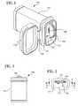
- FIG. 1is a perspective view of a storage vial for storing and dispensing test strips, according to a first exemplary embodiment of the present invention
- FIG. 2is a front view of the storage vial shown in FIG. 1 ;
- FIG. 3is a top view of the storage vial shown in FIG. 1 ;
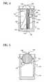
- FIG. 4is a sectional view taken along the line 4 - 4 in FIG. 3 ;
- FIG. 5is a sectional view taken along the line 5 - 5 in FIG. 3 ;
- FIG. 6is a partially cut-away perspective view of the storage vial shown in FIG. 1 , with a test strip partially dispensed;
- FIG. 7is a perspective view of the storage vial shown in FIG. 1 , with a motor for operating the dispenser;
- FIG. 8is a perspective view of a storage vial for storing and dispensing test strips according to a second exemplary embodiment of the present invention.
- FIG. 9is a top view of the storage vial shown in FIG. 8 ;
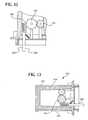
- FIG. 10is a sectional view taken along the line 10 - 10 in FIG. 9 ;
- FIG. 11is a sectional view taken along the line 11 - 11 in FIG. 9 ;
- FIG. 12is an enlarged sectional view of certain elements of the storage vial shown in FIG. 8 ;
- FIG. 13is a sectional view of a storage vial for storing and dispensing test strips according to a third exemplary embodiment of the present invention.
- FIG. 14is another sectional view of the storage vial shown in FIG. 13 ;
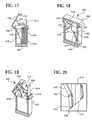
- FIG. 15is a cut-away perspective view of a storage vial for storing and dispensing test strips according to a fourth exemplary embodiment of the present invention.
- FIG. 16is an enlarged view of certain elements of the storage vial shown in FIG. 15 ;
- FIG. 17is a sectional view of the storage vial shown in FIG. 15 , with a partially dispensed test strip;
- FIG. 18is a cut-away perspective view of a storage vial for storing and dispensing test strips according to a fifth exemplary embodiment of the present invention.
- FIG. 19is a cut-away perspective view of the storage vial shown in FIG. 18 , with a partially dispensed test strip;
- FIG. 20is a perspective view of a linkage member of the storage vial shown in FIG. 18 ;
- FIG. 21is a sectional view of a storage vial for storing and dispensing test strips according to a sixth exemplary embodiment of the present invention.
- FIG. 22is a sectional view of a storage vial for storing and dispensing test strips according to a seventh exemplary embodiment of the present invention.
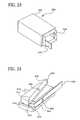
- FIG. 23is a perspective view of a storage vial for storing and dispensing test strips according to a eighth exemplary embodiment of the present invention.
- FIG. 24is perspective view of a cartridge of the storage vial shown in FIG. 23 .
- a storage vial 100 for storing and dispensing test stripsincludes a storage container 102 configured to store a stack of test strips 104 , a strip roller 106 rotatably disposed in the container, and a thumbwheel 108 rotatably disposed in the container.
- the strip roller 106contacts one test strip 142 of the stack of test strips 104 .
- the thumbwheel 108operates the strip roller 106 so that when the thumbwheel 108 is rotated, the strip roller 106 rotates to dispense the test strip 142 in contact with the strip roller 106 .
- the storage container 102includes a lower body portion 110 and a top wall 112 mounted in the lower body portion 110 .
- the lower body portion 110 of the storage container 102is generally rectangular and forms a cavity 123 which is configured to store a stack of test strips 104 .
- a test strip supporting wall 116extends upwardly from the bottom wall 118 of the container.
- the test strip supporting wall 116is tall enough to provide support for the stack of test strips 104 loaded in the storage container 102 .
- the test strip supporting wall 116may end short of the strip roller 106 so that it does not interfere with the strip roller 106 .
- the test strip supporting wallmay extend to the bottom surface of the top wall 112 of the storage container 102 , and have an elongated slot to provide clearance for installation and operation of the strip roller 106 (refer to element 331 in FIG. 14 ).
- the storage container 102may be formed of a desiccant entrained polymer to regulate the specific relative humidity inside the container.
- U.S. Pat. No. 5,911,937which is hereby incorporated by reference in its entirety, discloses one suitable desiccant entrained polymer.
- the storage container 102may be formed of a polymer with an insert-molded desiccant, or a desiccant may be placed in the cavity 123 .
- the top wall 112 of the storage container 102is preferably formed separately from the remainder of the storage container 102 for easier manufacturing and assembly. After the test strips 104 are loaded into the storage container 102 , the top wall 112 may be fixed to the storage container 102 by ultrasonic welding, by an adhesive, by mechanical engagement (such as a snap-fit), or by any other suitable method known to those skilled in the art.
- the top wall 112 of the storage container 102forms a dispensing slot 120 through which test strips are dispensed.
- the top surface 122 of the top wall 112may bear indicia 136 (such as an arrow) for indicating the direction to rotate the thumbwheel 108 to dispense a test strip.
- a first supporting member 124extends from the bottom surface 126 of the top wall 112 to rotatably support the strip roller 106 , as will be discussed in detail below.
- a second supporting member 128also extends from the bottom surface of the top wall 112 .
- the thumbwheel 108is rotatably supported by the second supporting member 128 , and the thumbwheel 108 extends through a second slot through the top wall 112 of the storage container 102 .
- a downwardly extending test strip supporting wallmay be located adjacent to the test strip dispensing slot 120 to support and guide test strips into the dispensing slot 120 while they are being dispensed (refer to element 831 in FIG. 14 ).
- the storage container 102may be provided with a lid 138 to prevent humidity and other environmental contaminants from entering the storage container 102 .
- the lid 138may be a separate component, but preferably the lid 138 is connected to the storage container 102 by a hinge 140 .
- the lid 138is formed integrally with the lower body portion 110 of the storage container 102 so that it is connected to the storage container 121 by a living hinge 140 .
- the lid 138preferably forms a substantially hermetic seal with the lower body portion 110 of the storage container 102 .
- Such sealsare known to those skilled in the art, and therefore, a detailed description of the seal will be omitted for conciseness. Also, for convenience of explanation, the lid is only shown in some of the drawings.
- a biasing element 132urges the stack of test strips 104 stored in the storage container 102 into contact with the strip roller 106 .
- a platform 134may be disposed between the biasing element 132 and the stack of test strips 104 to uniformly distribute the force generated by the biasing element 132 along the length of the stack of test strips 104 . If the test strips are sufficiently rigid, however, the biasing element 132 may directly contact the test strips.
- the strip roller 106is rotatably supported by the first supporting member 124 , which extends downwardly from the top wall 112 of the storage container 102 .
- the strip roller 106contacts one of the test strips 142 in the stack of test strips 104 .
- the strip roller 106engages the right-most test strip 142 .
- the strip roller 106engages the test strip in the upper portion of the test strip.
- the outer circumferential surface 144 of the strip roller 106should have a sufficient coefficient of friction to frictionally engage and dispense a test strip.
- the strip roller 106may be formed of rubber bonded to a metal or molded plastic roller insert.
- a strip roller gear 146is located on one side of the strip roller 106 .
- a thumbwheel 108is rotatably supported by the second supporting member 128 .
- a plurality of gear teeth 148are located around the outer circumference of the thumbwheel 108 , and the gear teeth 148 on the thumbwheel 108 engage the strip roller gear 146 .
- the gear teeth 148also provide friction to allow a user to more conveniently operate the thumbwheel 108 with a thumb, a finger, or the like.
- the storage container 102may be used in a fully automated test strip dispenser.
- the automated test strip dispenseris provided with a motor 150 with a pinion gear 152 , and the storage container 102 is disposed in the automated test strip dispenser so that the pinion gear 152 engages the thumbwheel 108 .
- the automated test strip dispensercan, if desired, be combined with a blood glucose meter that reads the test strips 104 .
- a locking member 154such as a ratchet or pawl, may be disposed on the storage container 102 to engage the thumbwheel 108 .
- the locking member 154allows the thumbwheel 108 to rotate in one direction (that is, a dispensing direction), but prevents the thumbwheel 108 from rotating in the opposite direction.
- the strip roller 106 and the thumbwheel 108are assembled to the first and second supporting members 124 , 128 , respectively, on the top wall 112 of the storage container 102 .
- a stack of test strips 104is loaded into the lower body portion 110 of the storage container 102 so that the stack of test strips 104 is disposed between the platform 132 and the test strip supporting wall 130 .
- the biasing element 132is installed in the cavity 123 between the platform 132 and the opposite wall of the storage container.
- the top wall 112with the strip roller 106 and the thumbwheel 108 installed, is then assembled to the lower body of the storage container 102 .
- the lid 138is placed on the storage container 102 to form a substantially hermetic seal.
- the storage vial 100may now be stored, and the stack of test strips 104 will be protected from environmental hazards, such as moisture. Typically, these steps will be performed by a manufacturer, rather than an end user of the storage vial.
- a useropens the lid 138 to expose the thumbwheel 108 and the strip dispensing slot 120 .
- the userthen rotates the thumbwheel 108 in the dispensing direction by manipulating the thumbwheel 108 , with the user's fingers or the like.
- the thumbwheel 108Upon rotation of the thumbwheel 108 , the thumbwheel 108 transmits the rotational force to the strip roller 106 through the gear teeth 148 on the thumbwheel 108 and the strip roller gear 146 . Therefore, the strip roller 106 rotates.
- the strip roller 106contacts one test strip 142 of the stack of test strips 104 , and through frictional force generated between the strip roller 106 and the contacted test strip 142 , dispenses the contacted test strip 142 through the test strip dispensing slot 120 .
- the thumbwheel 108may be rotated so that the test strip 142 is completely dispensed out of the storage container 102 , or the test strip 142 may be partially dispensed from the storage container 102 to expose the test strip so that a user may grasp the exposed test strip 142 to completely withdraw the test strip and use the test strip.
- the biasing element 132urges the remaining test strips in the stack of test strips 104 toward the strip roller 106 so that a new test strip is placed into contact with the strip roller 106 .
- the userrotates the thumbwheel 108 again. After dispensing the desired number of test strips, the user may then replace the lid on the storage container 102 to store the remaining test strips for future use.
- the storage vial 100may be discarded, or may be returned to the manufacturer for recycling.
- the storage container 102may be adapted to be reusable (e.g., by making the top wall 112 removable from the lower body portion 110 ).
- a storage vial 200 for storing and dispensing test stripsincludes a storage container 202 configured to store a stack of test strips 204 , a strip roller 206 rotatably disposed in the storage container 202 , and a pushbutton 208 disposed in the container.
- the strip roller 206contacts one test strip 226 of the stack of test strips 204 .
- the pushbutton 208is connected with the strip roller 206 by a gear train 230 so that when the pushbutton 208 is pushed, the strip roller 206 rotates to dispense the test strip 226 in contact with the strip roller.
- the storage container 202includes a lower body portion 210 and a top wall 212 mounted in the lower body portion 210 .
- the lower body portion 210 of the storage container 202is configured substantially the same as the lower body portion 110 of the storage container 100 of the first exemplary embodiment of the invention. Accordingly, a detailed description of the lower body portion 210 will not be repeated.
- the top wall 212 of the storage container 202has a test strip dispensing slot 216 through which test strips are dispensed.
- a first supporting member 218extends from the bottom surface 220 of the top wall 212 to rotatably support the strip roller 206 , as will be discussed in detail below.
- a second supporting member 222extends from the bottom surface 220 of the top wall 212 to rotatably support an intermediate gear 232 .
- the pushbutton 208has a first end 234 and a second end 236 .
- the first end 234 of the pushbutton 208extends through a slot located in the top wall 212 of the storage container 202 so that it may be manipulated by a user.
- the second end 236 of the pushbutton 208is disposed inside the cavity 214 of the storage container 202 .
- a rack gear 238is formed along the length of the pushbutton 208 near the second end 236 of the pushbutton 208 .
- the pushbuttonis movable between a resting position (illustrated in FIG. 10 , for example) and a dispensing position.
- a biasing element 240such as an extension spring, is disposed between the top wall 212 and the pushbutton 208 . The biasing element 240 urges the pushbutton 208 toward the resting position.
- the pushbutton 208has at least one track 242 located on one side of the pushbutton, and may have tracks located on both sides of the pushbutton 208 .
- the tracks 242are configured to guide the movement of the pushbutton 208 so that when the pushbutton 208 is pressed to dispense a test strip, the rack gear 238 on the pushbutton 208 engages the intermediate gear 232 .
- the tracks 242are configured to cause the rack gear 238 to disengage from the intermediate gear 232 . Therefore, the pushbutton 208 may be restored from the dispensing position to the resting position without rotating the intermediate gear 238 .
- the intermediate gear 232is rotatably disposed on the second supporting member 222 which extends downwardly from the bottom surface 220 of the top wall 212 of the storage container 202 .
- the intermediate gear 232is disposed between the rack gear 238 on the pushbutton 208 and the strip roller gear 228 on the strip roller 206 to operatively connect the gears and form a gear train 230 .
- the strip roller 206is rotatably supported by the first supporting member 218 , which extends downwardly from bottom surface 220 of the top wall 212 of the storage container 202 .
- the strip roller 206is generally configured the same as the strip roller 106 of the first exemplary embodiment of the present invention. Accordingly, a detailed description of the strip roller 206 will not be repeated.
- the strip roller 206 , the pushbutton 208 , the biasing element 240 , and the intermediate gear 232are assembled to the top wall 212 of the storage container 202 .
- a stack of test strips 204is loaded into the lower body portion 210 of the storage container 202 so that the stack of test strips 204 is disposed between the platform 246 (and the biasing element 232 ) and the test strip supporting wall 224 .
- the top wall 212with the installed components, is then assembled to the lower body portion 210 of the storage container 202 so that the strip roller 206 engages one test strip 226 of the stack of test strips 226 .
- the lid 224may then be closed, and the stack of test strips may be stored as long as desired.
- a useropens the lid 224 , and pushes the pushbutton 208 to move the pushbutton 208 from a resting position to a dispensing position.
- the tracks 242 on the pushbutton 208cause the rack gear 238 to engage the intermediate gear 232 . Consequently, movement of the pushbutton 208 causes the rack gear 238 to rotate the intermediate gear 232 .
- the rotation of the intermediate gear 232rotates the strip roller gear 228 and causes the strip roller 206 to dispense the test strip 226 which the strip roller 206 contacts.
- the pushbutton 208may be configured to completely dispense the test strip 226 out of the storage container 202 , or the test strip 226 may be partially dispensed from the storage container 202 to expose the test strip so that a user may grasp the exposed test strip 226 to completely withdraw the test strip from the storage container 202 .
- the biasing element 244urges the platform 246 and the stack of test strips 204 against the test strip supporting wall 248 so that a new test strip may be dispensed.
- the configuration of the tracks 242 on the pushbuttoncause the pushbutton 208 , along with the rack gear 238 , to move away from and disengage the intermediate gear 232 . Therefore, the pushbutton 208 may be returned to the resting position without rotating the intermediate and strip roller gears 232 , 228 in a reverse direction.
- a storage vial 300 for storing and dispensing test stripsincludes a storage container 302 configured to store a stack of test strips, a strip roller 306 rotatably disposed in the storage container 302 , and a pushbutton 308 disposed in the storage container 302 .
- the strip roller 306contacts one test strip of the stack of test strips.
- the pushbutton 308is connected with the strip roller 306 by a gear train so that when the pushbutton 308 is pushed, the strip roller 306 rotates to dispense the test strip in contact with the strip roller 306 .
- the storage container 302 of the third exemplary embodiment of the present inventionis generally the same as the storage container 202 of the second exemplary embodiment of the present invention, except for the configuration of the intermediate gear 316 of the gear train and the pushbutton 308 .
- the pushbutton 308does not have tracks for engaging and disengaging the rack gear from the intermediate gear 316 .
- the pushbutton 308has extended guide pins (not shown) which are disposed in and guided by pushbutton guide tracks 310 disposed on the inner surface of the outer wall of the lower body portion 304 of the storage container 302 .
- the guide tracks 310are generally parallel to the edge of the lower body portion so that the pushbutton member moves substantially straight into and out of the storage container 302 .
- the intermediate gear 316 of this embodiment of the inventionis not supported by a supporting member which extends from the top wall of the storage container. Instead, the intermediate gear 316 has extended shaft portions (not shown) which are disposed in and guided by a pair of intermediate gear guide tracks 312 formed on the inner surface of the outer wall of the lower body portion 304 of the storage container 302 . Accordingly, the intermediate gear 316 is free to move linearly along the length of the intermediate gear guide tracks 312 .
- the storage vial 300is loaded with a stack of test strips and assembled in substantially the same manner described above.
- a userpushes the pushbutton 308 to move the pushbutton 308 from a resting position to a dispensing position.
- a rack gear on the pushbutton 308engages the intermediate gear 316 , and the intermediate gear 316 moves linearly toward the lower end 314 of the intermediate gear guide tracks 312 .
- the guide tracks 312prevent the intermediate gear 316 from any further linear movement. Accordingly, further movement of the pushbutton 308 causes the rack gear on the pushbutton 308 to rotate the intermediate gear 316 .
- the rotation of the intermediate gear 316rotates a strip roller gear and causes the strip roller 306 to dispense a test strip.
- the pushbutton 308may be configured to completely dispense a test strip, or a test strip may be partially dispensed from the storage container 302 to expose the test strip so that a user may grasp the exposed test strip to completely withdraw the test strip from the storage container 302 .
- a biasing elementurges the pushbutton 308 from the dispensing position back to the resting position.
- the intermediate gear 316translates along the intermediate gear guide tracks 312 to move toward the upper end of the guide tracks.
- the pushbutton 308may be returned to the resting position without rotating the strip roller gear in a reverse direction.
- a storage vial 400 for storing and dispensing test stripsincludes a storage container 402 configured to store a stack of test strips 404 , a lid 406 connected to the storage container by a hinge 408 , and a linkage assembly 410 operatively connected to the lid 406 .
- the linkage assembly 410engages one test strip 412 of the stack of test strips 404 and dispenses the test strip 412 .
- the storage container 402has a generally rectangular lower body portion 414 and forms a cavity 416 which is configured to store a stack of test strips 404 .
- the storage container 402is formed of any suitable material, as previously discussed.
- the storage vial 400is provided with a lid 406 to prevent humidity and other environmental contaminants from entering the storage container.
- the lid 406is connected to the storage vial by a hinge 408 .
- the lid 406is formed integrally with the lower body portion of the storage container so that it is connected by a living hinge 408 . Any type of hinge arrangement may be used, however.
- the lid 406preferably forms a hermetic seal with the lower body portion 414 of the storage container 402 .
- the linkage assembly 410includes a first arm member 418 connected to the lid 406 , a second arm member 420 connected to the first arm member 418 by a living hinge 428 , and a third arm member 422 connected to the second arm member 420 by a living hinge 428 .
- the first arm member 418is a generally V-shaped member. The two legs of the V-shaped member form, in the illustrated embodiment, an obtuse angle with respect to one another.
- the first arm member 418is attached to the lid 406 by heat staking, by ultrasonic welding, by mechanical attachment, or by any other suitable method known to those skilled in the art.
- the second arm member 420joins the first and third arm members 418 , 422 by living hinges 428 at both ends of the second arm.
- living hingesprovide certain benefits, such as lower manufacturing costs, but it should be understood that the arms also may be joined by other types of hinges.
- the third arm member 422has guide members 430 , such as guide pins, which are disposed in and configured to travel in rails located in the side wall of the lower body portion 414 of the storage container 402 .
- the third arm member 422has a lower contacting member 426 which is configured to contact the lower edge of one test strip 412 of the stack of test strips 404 .
- the third arm member 422contacts the lower edge of the right-most test strip 412 .
- one set of first, second, and third arm membersis provided at the front side of the storage container 402 .
- a second set of first, second, and third arm memberswhich is substantially identical to the first set of first, second, and third arm members, may be located at the back side of the storage container 402 .
- the lid 406is opened, a stack of test strips 404 is loaded into the container between a platform 432 and the outer wall 434 of the storage container 402 , and the lid 406 is closed. With the lid 406 closed, the linkage assembly 410 is placed into a resting position. In the resting position, the third arm member 422 is located at the bottom of the storage container, and the lower contacting member 426 is located underneath the bottom edge of the right-most test strip 412 .
- a useropens the lid 406 of the storage container 402 .
- the opening of the lid 406causes the first arm member 418 to rotate up and out of the storage container.
- the second and third arm members 420 , 422which are connected to the first arm member 418 , are also raised.
- the third arm member 422travels substantially vertically up due to the cooperation of the guide member 430 and the guide rails and is raised up to a dispensing position. Since the lower contacting member 426 of the third arm member 422 is located under a test strip 412 , it raises and dispenses the test strip 412 .
- the first, second, and third arm members 418 , 420 , and 422may be configured to completely dispense the test strip 412 out of the storage container 402 , or the test strip 412 may be partially dispensed from the storage container 402 to expose the test strip so that a user may grasp the exposed test strip 412 to completely withdraw the test strip from the storage container 402 and use the test strip.
- a usermay then close the lid 406 .
- Closing the lid 406causes the linkage assembly 410 to return to its resting position.
- the linkage assembly 410and the third arm member 422 in particular, reaches the resting position, the biasing element 436 urges the stack of test strips 404 toward the outer wall 434 so that a new test strip is placed over the lower contacting member 426 of the new test strip. Consequently, the storage vial 400 is ready to dispense another test strip.
- a storage vial 500 for storing and dispensing test stripsincludes a storage container 502 configured to store a stack of test strips, a lid 504 connected to the storage container 502 by a hinge 506 , and a linkage assembly 508 operatively connected to the lid 504 .
- the linkage assembly 508engages one test strip 510 of the stack of test strips and dispenses the test strip.
- the storage container 502 and lid 504 of this embodimentis generally configured the same as the storage container 402 and lid 404 of the fourth exemplary embodiment.
- the linkage assembly 508includes at least one slider arm 512 , at least one first linkage member 514 , and at least one second linkage member 516 .
- a pair of slider arms 512 , a pair of first linkage members 514 , and a pair of second linkage members 516are provided to increase the stability and reliability of the linkage assembly.
- First ends 518 of the slider arms 512are pivotably connected to the lid 504 .
- Second ends 520 of the slider arms 512are pivotably connected to the first linkage members 514 .
- Each of the slider arms 512has a slot 522 that engages a guide boss 536 disposed on the storage container 502 .
- First ends 524 of the first linkage members 514are pivotably connected to the second ends 520 of the slider arms 512 , and second ends 526 of the first linkage members 514 are pivotably connected to the second linkage members 516 .
- the second linkage members 516have guide members 528 , such as guide pins, which are disposed in and configured to travel in guide rails located in the side walls of the storage container 502 .
- the first ends 530 of the second linkage members 516are connected to the second ends 526 of the first linkage members 514 .
- a lower contacting member 534is disposed between the second ends 532 of the second linkage members 516 . The lower contacting member contacts one test strip 510 so that the test strip 510 is dispensed when the lid 504 is opened.
- the lid 504is opened, a stack of test strips is loaded into the storage container 502 , and the lid 504 is closed. With the lid 504 closed, the linkage assembly 508 is placed into a resting position. In the resting position, the second linkage members 516 are located at the bottom of the storage container 502 , and the lower contacting member 534 is located underneath the lower edge of the bottom edge of the right-most test strip 510 .
- a useropens the lid 504 of the storage container 502 .
- the opening of the lid 504causes the slider arms 512 to rotate up and out of the storage container 502 .
- the slider arms 512are guided by cooperation of the guide bosses 536 and the slots in the slider arms 512 along a predetermined path.
- the second ends 520 of the slider arms 512pull the first linkage members 514 , which, in turn, pull the second linkage members 516 .
- the second linkage members 516travel substantially vertically up insider the storage container 502 due to the cooperation of the guide members 528 and guide rails and is raised up to a dispensing position.
- the lower contacting member 534Since the lower contacting member 534 is located under a test strip, it raises and dispenses the test strip. Once the second linkage members 516 reach the dispensing position, a user may grasp the test strip and remove the dispensed test strip.
- the slider arms 512 and the first and second linkage members 514 , 516may be configured to completely dispense a test strip out of the storage container 502 , or the test strip may be partially dispensed from the storage container 502 to expose the test strip so that a user may grasp the exposed test strip to completely withdraw the test strip from the storage container and use the test strip.
- a usermay then close the lid 504 .
- Closing the lid 504causes the linkage assembly 508 to return to its resting position.
- a biasing elementurges the stack of test strips towards the side wall of the storage container 502 so that a new test strip is placed over the lower contacting member. Consequently, the storage container 502 is ready to dispense another test strip.
- a storage vial 600 for storing and dispensing test stripsincludes a storage container 602 configured to store a stack of test strips, a spiral pusher spring 604 , and a thumbwheel 606 connected to the spiral pusher spring 604 by a gear train 628 so that rotation of the thumbwheel 606 causes the spring to dispense one test strip of the stack of test strips.
- the storage container 602is generally rectangular and forms a cavity 612 which is configured to receive a cartridge 610 for storing a stack of test strips.
- the storage container 602may be formed of any suitable material, as previously discussed.
- the storage vial 600is provided with a lid 608 to prevent humidity and other environmental contaminants from entering the storage container 602 .
- the lid 608may be connected to the storage vial by any suitable type of hinge, such as a living hinge.
- a cartridge 610is inserted into the cavity in the storage container 602 .
- the spiral pusher spring 604 and the associated gear train 628are disposed in the cartridge 610 .
- the cavity 612 in the cartridge 610is configured to hold a stack of test strips, and a platform, as well as a biasing element, are located in the cavity to urge the stack of elements toward one wall of the cartridge 610 .
- the cartridge 610may be removable from the storage container 602 or permanently affixed thereto.
- the spiral pusher spring 604is wound around a cylindrical spring drum 614 .
- a first end 616 of the spiral pusher spring 604is disposed in a guide track 618 formed in the cartridge 610 .
- a second end 620 of the spiral pusher spring 604is fixed to the cylindrical spring drum 614 .
- the first end 616 of the spiral pusher spring 604is configured to contact the edge of a test strip. Accordingly, when the spring drum 614 is rotated, the first end 616 of the spiral pusher spring 604 is extended and moves along the guide track 618 to dispense a test strip.
- the gear train 628comprises a thumbwheel driving gear 606 , a first idler gear 622 , a second idler gear 624 , and a spring drum driving gear. 626 .
- the thumbwheel driving gear 606is partially exposed to the outside of the storage container 602 so that a user may manipulate the thumbwheel 606 .
- the first and second idler gears 622 , 624engage the thumbwheel 606 , and transmit a rotational force generated by the thumbwheel 606 to the spring drum driving gear 626 .
- the gear train 628may be configured with any desired gear ratios.
- a stack of test stripsis loaded into the cartridge 610 , the spiral pusher spring 604 is retracted into an initial resting position, and the cartridge is inserted into the storage container 602 . In the resting position, the spiral pusher spring 604 is retracted so that the end of the spring is located at the bottom of the storage container 602 and is underneath the lower edge of one edge of a test strip.
- a userrotates the exposed thumbwheel 606 in a dispensing direction.
- the rotational force of the thumbwheel 606is transmitted to the spiral pusher spring 604 through the gear train 628 .
- the spiral pusher spring 604is extended and dispenses the test strip.
- the thumbwheel 606may be rotated so that the test strip is completely dispensed out of the storage container 602 , or the test strip may be partially dispensed from the storage container 602 to expose the test strip so that a user may grasp the exposed test strip to completely withdraw the test strip and use the test strip.
- a usermay then rotate the thumbwheel 606 in an opposite direction to the dispensing direction to return the spiral pusher spring 604 to its resting position.
- the inherent spring force of the spiral pusher spring 604may cause it to return to its resting position automatically.
- the biasing elementurges the stack of test strips towards the spiral spring so that a new test strip is placed over the end of the pusher spring. Consequently, the storage container 602 is ready to dispense another test strip.
- a storage vial 700 for storing and dispensing test stripsincludes a storage container 702 configured to store a stack of test strips, a spring 704 configured to contact one test strip of the stack of test strips, a rack 706 connected to the spring 704 , a pinion 708 engaging the rack 706 , and a thumbwheel 710 engaging the pinion 708 so that rotation of the thumbwheel 710 displaces the rack 706 and causes the spring 704 to dispense the contacted test strip.
- the storage container 702 and lid of this embodimentis generally configured the same as the storage container 702 and lid of the sixth exemplary embodiment.
- a cartridge 712is inserted into a cavity 714 in the storage container 702 502 .
- the cartridge 712has a cavity which is configured to hold a stack of test strips, and a platform, as well as a biasing element, are located in the cartridge 712 to urge the stack of test strips toward one wall of the cartridge 712 .
- the cartridge 712may be removable from the storage container 602 or permanently affixed thereto.
- the spring 704is disposed in a guide track 722 formed in the cartridge 712 .
- a first end 716 of the spring 704is guided by the guide track 722 and is configured to contact the edge of a test strip.
- a second end 718 of the spring 704is fixed to the rack 706 .
- the rack 706is linearly movable within the storage container 702 .
- the rack 706has a rack gear 720 located on one side of the rack.
- a pinion gear 708is rotatably disposed on the cartridge 712 , and engages the rack gear 720 .
- the thumbwheel 710is also rotatable disposed on the cartridge 712 , and engages the pinion gear 708 . Accordingly, when the thumbwheel 710 is rotated, the pinion gear 708 rotates, and the rack 706 translates linearly. Thus, the first end of the attached spring 704 is moved along the guide track 722 .
- a stack of test stripsis loaded into the cartridge 712 , the pusher spring 704 and rack 706 are placed into an initial resting position, and the cartridge is inserted into the storage container 702 . In the resting position, the rack 706 and pusher spring 704 are retracted so that the end of the spring 704 is located at the bottom of the storage container 702 and is underneath the lower edge of one edge of a test strip.
- a userrotates the exposed thumbwheel 710 in a dispensing direction.
- the rotational force of the thumbwheel 710is transmitted to the pinion 708 gear, and the pinion gear 708 engages the rack 706 gear to translate the rotational force of the pinion gear 708 into linear movement of the rack 706 .
- the linear movement of the rack 706extends the pusher spring 704 , and dispenses the test strip.
- the thumbwheel 710may be rotated so that the test strip is completely dispensed out of the storage container 702 , or the test strip may be partially dispensed from the storage container 702 to expose the test strip so that a user may grasp the exposed test strip to completely withdraw the test strip and use the test strip.
- a usermay then rotate the thumbwheel 710 in an opposite direction to the dispensing direction to return the pusher spring 704 to its resting position.
- the pusher springcan return to its resting position automatically.
- the biasing elementurges the stack of test strips towards the pusher spring 704 so that a new test strip is placed over the end of the pusher spring 704 . Consequently, the storage container 702 is ready to dispense another test strip.
- a storage vial 800 for storing and dispensing test stripsincludes a storage container 802 configured to store a stack of test strips rack, a spring 804 configured to contact one test strip of the stack of test strips, and a lever arm 806 that pivots about a pivot point 808 .
- a first end 810 of the lever arm 806is connected to the spring 804 to drive the spring 804 so that pivoting of the lever causes the spring 804 to dispense the contacted test strip.
- the storage container 802 and lid (not shown) of this embodimentis generally configured the same as the storage container 602 and lid 608 of the sixth exemplary embodiment.
- a cartridge 814is inserted into a cavity in the storage container 802 .
- a cavity in the cartridge 814is configured to hold a stack of test strips, and a platform, as well as a biasing element, are located in the cavity to urge the stack of test strips toward one wall of the cartridge.
- the cartridge 814may be removable from the storage container 802 or permanently affixed thereto.
- the spring 804is disposed in a guide track 818 formed by the cartridge and 814 .
- the first end 820 of the spring 804is guided by the guide track 818 and is configured to contact the edge of a test strip 816 .
- a second end 822 of the spring 804is fixed to a first end 810 of the lever arm 806 .
- the lever arm 806is pivotably disposed about a pivot point 808 on the cartridge.
- the second end 824 of the lever arm 806extends above the top end of the cartridge so that a user may manipulate the lever arm 806 .
- a stack of test stripsis loaded into the cartridge 814 , the lever arm 806 and the pusher spring 804 are placed into an initial resting position, and the cartridge is inserted into the storage container 802 .
- the lever arm 806is pivoted to one side of the storage container 802 , and the pusher spring 804 is retracted so that the end of the spring 804 is located at the bottom of the storage container 802 and is underneath the lower edge of one edge of a test strip.
- a userpresses the lever arm 806 to pivot the lever arm 806 .
- the pivoting of the lever arm 806causes the pusher spring 804 to extend along the guide track, and dispenses the test strip.
- the lever arm 806is pivoted far enough for a user to grasp the test strip and remove the dispensed test strip.
- a usermay then pivot the lever arm 806 back to its initial resting position.
- the lever armmay return to its resting position automatically.
- the biasing elementurges the stack of test strips towards the pusher spring 804 so that a new test strip is placed over the end of the pusher spring 804 . Consequently, the storage container 802 is ready to dispense another test strip.
Landscapes
- Engineering & Computer Science (AREA)
- Health & Medical Sciences (AREA)
- Biomedical Technology (AREA)
- Life Sciences & Earth Sciences (AREA)
- Physics & Mathematics (AREA)
- Mechanical Engineering (AREA)
- Chemical & Material Sciences (AREA)
- Medicinal Chemistry (AREA)
- General Physics & Mathematics (AREA)
- Urology & Nephrology (AREA)
- Hematology (AREA)
- Food Science & Technology (AREA)
- Biophysics (AREA)
- Analytical Chemistry (AREA)
- Biochemistry (AREA)
- General Health & Medical Sciences (AREA)
- Molecular Biology (AREA)
- Immunology (AREA)
- Pathology (AREA)
- Optics & Photonics (AREA)
- Automatic Analysis And Handling Materials Therefor (AREA)
- Containers And Packaging Bodies Having A Special Means To Remove Contents (AREA)
- Investigating Or Analysing Biological Materials (AREA)
- Analysing Materials By The Use Of Radiation (AREA)
Abstract
Description
Claims (7)
Priority Applications (16)
| Application Number | Priority Date | Filing Date | Title |
|---|---|---|---|
| US11/430,178US7887757B2 (en) | 2006-05-09 | 2006-05-09 | Method and apparatus for dispensing diagnostic test strips |
| CA2587993ACA2587993C (en) | 2006-05-09 | 2007-05-08 | Method and apparatus for dispensing diagnostic test strips |
| ES11151979TES2407649T3 (en) | 2006-05-09 | 2007-05-09 | Method and apparatus for dispensing diagnostic test strips |
| DE602007013964TDE602007013964D1 (en) | 2006-05-09 | 2007-05-09 | Method and device for dispensing diagnostic test strips |
| ES11152085TES2422902T3 (en) | 2006-05-09 | 2007-05-09 | Method and apparatus for dispensing diagnostic test strips |
| EP11152085.4AEP2327639B1 (en) | 2006-05-09 | 2007-05-09 | Method and apparatus for dispensing diagnostic test strips |
| JP2007124509AJP5268281B2 (en) | 2006-05-09 | 2007-05-09 | Method and apparatus for dispensing diagnostic test strips |
| ES07107830TES2364777T3 (en) | 2006-05-09 | 2007-05-09 | METHOD AND APPARATUS FOR DISPENSING DIAGNOSTIC TEST STRIPS. |
| AT07107830TATE506287T1 (en) | 2006-05-09 | 2007-05-09 | METHOD AND DEVICE FOR DISPENSING DIAGNOSTIC TEST STRIPS |
| EP07107830AEP1854738B1 (en) | 2006-05-09 | 2007-05-09 | Method and Apparatus for Dispensing Diagnostic Test Strips |
| EP11151979AEP2360106B1 (en) | 2006-05-09 | 2007-05-09 | Method and apparatus for dispensing diagnostic test strips |
| US12/923,268US9039977B2 (en) | 2006-05-09 | 2010-09-13 | Method and apparatus for dispensing diagnostic test strips |
| US12/923,267US8652415B2 (en) | 2006-05-09 | 2010-09-13 | Method and apparatus for dispensing diagnostic test strips |
| JP2013097699AJP5948279B2 (en) | 2006-05-09 | 2013-05-07 | Method and apparatus for dispensing diagnostic test strips |
| JP2013097687AJP5657740B2 (en) | 2006-05-09 | 2013-05-07 | Method and apparatus for dispensing diagnostic test strips |
| US14/181,443US9372184B2 (en) | 2006-05-09 | 2014-02-14 | Method and apparatus for dispensing diagnostic test strips |
Applications Claiming Priority (1)
| Application Number | Priority Date | Filing Date | Title |
|---|---|---|---|
| US11/430,178US7887757B2 (en) | 2006-05-09 | 2006-05-09 | Method and apparatus for dispensing diagnostic test strips |
Related Child Applications (2)
| Application Number | Title | Priority Date | Filing Date |
|---|---|---|---|
| US12/923,267DivisionUS8652415B2 (en) | 2006-05-09 | 2010-09-13 | Method and apparatus for dispensing diagnostic test strips |
| US12/923,268DivisionUS9039977B2 (en) | 2006-05-09 | 2010-09-13 | Method and apparatus for dispensing diagnostic test strips |
Publications (2)
| Publication Number | Publication Date |
|---|---|
| US20070264165A1 US20070264165A1 (en) | 2007-11-15 |
| US7887757B2true US7887757B2 (en) | 2011-02-15 |
Family
ID=38441865
Family Applications (4)
| Application Number | Title | Priority Date | Filing Date |
|---|---|---|---|
| US11/430,178Active - Reinstated2028-11-05US7887757B2 (en) | 2006-05-09 | 2006-05-09 | Method and apparatus for dispensing diagnostic test strips |
| US12/923,267Active2026-05-14US8652415B2 (en) | 2006-05-09 | 2010-09-13 | Method and apparatus for dispensing diagnostic test strips |
| US12/923,268Active2026-06-02US9039977B2 (en) | 2006-05-09 | 2010-09-13 | Method and apparatus for dispensing diagnostic test strips |
| US14/181,443Expired - Fee RelatedUS9372184B2 (en) | 2006-05-09 | 2014-02-14 | Method and apparatus for dispensing diagnostic test strips |
Family Applications After (3)
| Application Number | Title | Priority Date | Filing Date |
|---|---|---|---|
| US12/923,267Active2026-05-14US8652415B2 (en) | 2006-05-09 | 2010-09-13 | Method and apparatus for dispensing diagnostic test strips |
| US12/923,268Active2026-06-02US9039977B2 (en) | 2006-05-09 | 2010-09-13 | Method and apparatus for dispensing diagnostic test strips |
| US14/181,443Expired - Fee RelatedUS9372184B2 (en) | 2006-05-09 | 2014-02-14 | Method and apparatus for dispensing diagnostic test strips |
Country Status (7)
| Country | Link |
|---|---|
| US (4) | US7887757B2 (en) |
| EP (3) | EP1854738B1 (en) |
| JP (3) | JP5268281B2 (en) |
| AT (1) | ATE506287T1 (en) |
| CA (1) | CA2587993C (en) |
| DE (1) | DE602007013964D1 (en) |
| ES (3) | ES2422902T3 (en) |
Cited By (8)
| Publication number | Priority date | Publication date | Assignee | Title |
|---|---|---|---|---|
| US20100059539A1 (en)* | 2007-02-27 | 2010-03-11 | Jean-Pierre Giraud | Bulk dispenser for pre-cut edible film |
| US20110253736A1 (en)* | 2010-04-16 | 2011-10-20 | Frank David Fujimoto | Analyte test strip vial |
| US20130020347A1 (en)* | 2011-06-10 | 2013-01-24 | Union Street Brand Packaging | Strip Dispenser |
| US20140277707A1 (en)* | 2013-03-15 | 2014-09-18 | Makefield Llc | Dispensing systems with supplemental functions |
| US20150136162A1 (en)* | 2012-05-15 | 2015-05-21 | Albea Services | Device for dispensing artificial eyelashes |
| US20160236506A1 (en)* | 2015-02-14 | 2016-08-18 | Kristin Michelle Davis | Writing Instrument Having A Replaceable Sleeve |
| US10633135B2 (en) | 2014-08-05 | 2020-04-28 | Hero Health, Inc. | Dispensable unit retrieval mechanism |
| US12336969B2 (en) | 2020-12-31 | 2025-06-24 | Hero Health Inc. | Sensing retrieval of pills |
Families Citing this family (41)
| Publication number | Priority date | Publication date | Assignee | Title |
|---|---|---|---|---|
| US7858046B2 (en)* | 2006-09-14 | 2010-12-28 | Bayer Healthcare Llc | Detachable test sensor container having a system for reducing coding errors |
| US20080217353A1 (en)* | 2007-03-06 | 2008-09-11 | Michael John Newman | Method of Dispensing A Test Strip |
| GB2443893B (en)* | 2007-03-19 | 2009-06-24 | Donald Dallas | A dispensing mechanism |
| US20080230554A1 (en)* | 2007-03-23 | 2008-09-25 | Randolph Maryann | Chewing gum dispenser |
| WO2009064231A1 (en)* | 2007-11-15 | 2009-05-22 | Sca Hygiene Products Ab | Dispenser for absorbent articles |
| CA2967105C (en) | 2008-05-15 | 2019-07-02 | Csp Technologies, Inc. | Vial with non-round seal |
| US8684172B2 (en)* | 2008-12-02 | 2014-04-01 | Bayer Healthcare Llc | Analyte sensor container systems with sensor elevator and storage methods |
| US8574510B2 (en) | 2009-09-30 | 2013-11-05 | Bayer Healthcare Llc | Stackable electrochemical analyte sensors, systems and methods including same |
| US8550295B2 (en)* | 2010-02-22 | 2013-10-08 | Roche Diagnostics Operations, Inc. | Container for dispensing a single test strip |
| CA2730432A1 (en)* | 2010-03-05 | 2011-09-05 | Unique & Handy Corp. | Box and system for dispensing a product |
| JP5476174B2 (en)* | 2010-03-19 | 2014-04-23 | 大王製紙株式会社 | Household thin paper storage container |
| US20110278321A1 (en)* | 2010-05-11 | 2011-11-17 | Roche Diagnostics Operations, Inc. | Hermetically sealed test strip container |
| WO2012138451A2 (en)* | 2011-04-08 | 2012-10-11 | Csp Technologies, Inc. | Strip dispenser and strips for use with the same |
| US9924892B2 (en)* | 2011-05-31 | 2018-03-27 | Tara Chand Singhal | Integrated blood glucose measuring device |
| US10352921B2 (en)* | 2011-05-31 | 2019-07-16 | Tara Chand Singhal | Integrated blood glucose measuring device with a test strip packaging system |
| WO2013096268A1 (en) | 2011-12-20 | 2013-06-27 | Bayer Heal Thcare Llc | Linear, cartridge-based glucose measurement system |
| EP2618144A1 (en) | 2012-01-18 | 2013-07-24 | Medical Device UG | Method and container for loading a measuring device with measuring units |
| US9383333B2 (en) | 2012-05-31 | 2016-07-05 | Ascensia Diabetes Care Holdings Ag | Replaceable multistrip cartridge and biosensor meter |
| WO2013180755A1 (en) | 2012-05-31 | 2013-12-05 | Bayer Healthcare Llc | Multistrip cartridge |
| CN103057848B (en)* | 2013-01-09 | 2016-03-02 | 中南大学湘雅二医院 | A kind of ampoule neck is sterilized anti-dandruff containing the convenient taking device of the cotton formula of liquid |
| US9347930B2 (en) | 2013-02-01 | 2016-05-24 | Sanofi-Aventis Deutschland Gmbh | Dispensing mechanism for test strips |
| KR101787857B1 (en)* | 2013-02-04 | 2017-10-18 | 끌라리앙 프로딕숑 (프랑스) 에스.아.에스. | Dispensing device for holding and dispensing strip-like objects |
| JP6563892B2 (en) | 2013-03-11 | 2019-08-21 | アセンシア・ディアベティス・ケア・ホールディングス・アーゲー | Strip grabber |
| CA2904689A1 (en) | 2013-03-12 | 2014-10-09 | Bayer Healthcare Llc | Test strip meter with a mechanism for pushing the test strip against an optical reader |
| US9376708B2 (en) | 2013-03-13 | 2016-06-28 | Ascensia Diabetes Care Holdings Ag | Bottled glucose sensor with no handling |
| US10315833B2 (en)* | 2013-11-07 | 2019-06-11 | Accutec Blades, Inc. | Blade dispenser |
| KR101494318B1 (en)* | 2014-01-14 | 2015-02-26 | 허윤아 | Case for sheet or papers |
| EP3369017A4 (en)* | 2015-10-28 | 2019-06-12 | Sikorsky Aircraft Corporation | Protective cover and gear assembly |
| US10259642B2 (en)* | 2015-12-17 | 2019-04-16 | Accutec Blades, Inc. | Blade dispenser |
| US10265700B2 (en)* | 2016-11-11 | 2019-04-23 | Samuel Messinger | System for improving diabetes testing and reducing counterfeiting |
| AT520530B1 (en)* | 2018-02-14 | 2019-05-15 | Pez Ag | Pill dispenser |
| US10709229B2 (en)* | 2018-04-10 | 2020-07-14 | Brian Edward McGuinness | Garment and accessory with bag pulling system |
| CN108957021B (en)* | 2018-07-05 | 2024-06-28 | 嘉兴凯实生物科技股份有限公司 | Single-gun reagent strip taking and beating device |
| CN110182476B (en)* | 2019-06-06 | 2020-10-23 | 泰州泰慧达科技信息咨询中心 | Medical collagen sponge piece spits out case |
| CN110861823B (en)* | 2019-12-09 | 2020-07-24 | 张艳艳 | A device for containing blood sugar test strips |
| FR3104561B1 (en)* | 2019-12-16 | 2022-03-04 | Biomerieux Sa | Strip storage and dispensing device |
| FR3109869A1 (en)* | 2020-05-07 | 2021-11-12 | Formes Et Sculptures | Perfume tester device |
| CN111634533B (en)* | 2020-06-15 | 2022-12-06 | 帕蒙兰德(宁夏)生物技术有限公司 | Plastic bag storage box beneficial to environmental protection |
| CN112607457B (en)* | 2020-12-21 | 2022-11-22 | 泉州铕之易工程管理有限公司 | Marketing is with propaganda list granting device |
| CN116101607B (en)* | 2023-04-13 | 2023-06-16 | 佳木斯大学 | Storage for disposable reagent strips |
| CN117944985B (en)* | 2024-02-06 | 2025-09-12 | 苏州逸动健康科技有限公司 | Arrangement device for culture apparatus for drug screening |
Citations (32)
| Publication number | Priority date | Publication date | Assignee | Title |
|---|---|---|---|---|
| US3269591A (en)* | 1964-12-03 | 1966-08-30 | William W Harter | Paper dispenser with flywheel |
| DE3001332A1 (en) | 1980-01-16 | 1981-07-23 | Fritz 8730 Bad Kissingen Herzig | Ignition strip pocket dispenser - has strip packet spring loaded against knurled rollers turned by protruding hand wheel |
| US4324345A (en) | 1980-03-07 | 1982-04-13 | Martinez Manuel M | Dispenser for automatically dispensing permanent wave tissue sheets |
| US4783056A (en) | 1986-11-10 | 1988-11-08 | Abrams Robert S | Process for making an aseptic vial and cap |
| US4812116A (en) | 1986-11-10 | 1989-03-14 | Abrams Robert S | Mold for making an aseptic vial and cap |
| US4911344A (en) | 1988-03-23 | 1990-03-27 | Tek-Aids Inc. | Strip dispenser box |
| US5018614A (en)* | 1990-01-08 | 1991-05-28 | Theodor Braun, Ges, M.B.H | Ticket vending machine |
| US5280845A (en)* | 1992-10-15 | 1994-01-25 | Leight Howard S | Earplug dispenser |
| US5489414A (en) | 1993-04-23 | 1996-02-06 | Boehringer Mannheim, Gmbh | System for analyzing compounds contained in liquid samples |
| US5510266A (en) | 1995-05-05 | 1996-04-23 | Bayer Corporation | Method and apparatus of handling multiple sensors in a glucose monitoring instrument system |
| US5632410A (en) | 1995-04-17 | 1997-05-27 | Bayer Corporation | Means of handling multiple sensors in a glucose monitoring instrument system |
| US5723085A (en) | 1994-10-14 | 1998-03-03 | Capitol Vial, Inc. | Process and apparatus for making a leak proof cap and body assembly |
| US5738244A (en) | 1995-01-13 | 1998-04-14 | Bayer Corporation | Dispensing instrument for fluid monitoring sensors |
| US5810199A (en) | 1996-06-10 | 1998-09-22 | Bayer Corporation | Dispensing instrument for fluid monitoring sensor |
| US5854074A (en) | 1995-03-14 | 1998-12-29 | Bayer Corporation | Dispensing instrument for fluid monitoring sensors |
| US5911937A (en) | 1995-04-19 | 1999-06-15 | Capitol Specialty Plastics, Inc. | Desiccant entrained polymer |
| US6176119B1 (en) | 1997-12-13 | 2001-01-23 | Roche Diagnostics Gmbh | Analytical system for sample liquids |
| US6213343B1 (en) | 1998-10-13 | 2001-04-10 | Avery Dennison Corporation | Portable sterile bandage dispenser |
| US6379317B1 (en) | 1997-11-28 | 2002-04-30 | Hans Kintzig | Analytical measuring device with lancing device |
| US20020125628A1 (en)* | 2001-03-09 | 2002-09-12 | Pao-Jung Chen | Locating structure of a card-dispensing stop board of a card device |
| US6475436B1 (en) | 1999-01-23 | 2002-11-05 | Roche Diagnostics Gmbh | Method and device for removing consumable analytic products from a storage container |
| US6497845B1 (en) | 1998-04-24 | 2002-12-24 | Roche Diagnostics Gmbh | Storage container for analytical devices |
| US20030121932A1 (en) | 2001-12-27 | 2003-07-03 | Krystyna Wajda | Apparatus for dispensing flat articles |
| US20050017018A1 (en) | 2001-12-05 | 2005-01-27 | Von Falkenhausen Christian | Dispensing device for flat dosage forms |
| US20050057602A1 (en)* | 2003-08-01 | 2005-03-17 | Brother Kogyo Kabushiki Kaisha | Inkjet printer |
| US6872358B2 (en) | 2002-01-16 | 2005-03-29 | Lifescan, Inc. | Test strip dispenser |
| US20050082742A1 (en)* | 2003-08-13 | 2005-04-21 | Samsung Electronics Co., Ltd. | Inkjet printer and paper feeding method therefor |
| WO2005051822A1 (en) | 2003-11-24 | 2005-06-09 | Csp Technologies, Inc. | Moisture-tight edible film dispenser and method thereof |
| US6908008B2 (en) | 2001-12-21 | 2005-06-21 | Lifescan, Inc. | Test device with means for storing and dispensing diagnostic strips |
| US6941948B2 (en)* | 2002-03-07 | 2005-09-13 | Vectura Drug Delivery | Medicament storage and delivery devices |
| US6988996B2 (en) | 2001-06-08 | 2006-01-24 | Roche Diagnostics Operatons, Inc. | Test media cassette for bodily fluid testing device |
| US20070215634A1 (en)* | 2006-03-15 | 2007-09-20 | Marda Medical | Individual containers for use in medical pad warming units |
Family Cites Families (30)
| Publication number | Priority date | Publication date | Assignee | Title |
|---|---|---|---|---|
| US2269525A (en)* | 1938-12-16 | 1942-01-13 | Fleischer Nathan | Carbon paper container |
| US3094323A (en)* | 1961-06-16 | 1963-06-18 | Salvatore J Catania | End papers for hair-waving and dispenser therefor |
| US3276622A (en)* | 1964-04-01 | 1966-10-04 | Milprint Inc | Dispenser carton |
| GB1573084A (en)* | 1978-05-23 | 1980-08-13 | Ross H | Dispenser for light sensitive papers |
| JPS6121417Y2 (en)* | 1979-03-05 | 1986-06-26 | ||
| JPS55127074A (en) | 1979-03-26 | 1980-10-01 | Canon Inc | Photoelectric transfer element with high molecular film as substrate |
| GB2210603A (en)* | 1987-10-02 | 1989-06-14 | Philip Nigel Record | Card dispenser |
| US5197630A (en)* | 1991-11-25 | 1993-03-30 | Kirla Stanley J | Dispenser for nested conical articles |
| US5687876A (en)* | 1993-05-14 | 1997-11-18 | Lucas, Jr.; Orlan R. | Method and improved apparatus for separating and dispensing coffee filters |
| FR2709475B3 (en)* | 1993-09-02 | 1995-07-13 | Bricaud Piron Ets | Card distributor, including business cards. |
| JPH09250998A (en) | 1996-03-14 | 1997-09-22 | Daikin Ind Ltd | Concentration measuring device |
| JPH10253570A (en) | 1997-03-14 | 1998-09-25 | Daikin Ind Ltd | Concentration measuring device |
| CA2230417A1 (en)* | 1998-02-25 | 1999-08-25 | Brian Conway | Business card dispenser |
| DE19811622A1 (en)* | 1998-03-17 | 1999-09-23 | Lre Technology Partner Gmbh | Laboratory instrument incorporating split test card housing |
| JP4283382B2 (en) | 1999-07-06 | 2009-06-24 | 株式会社コナミデジタルエンタテインメント | Confectionery dispenser |
| AU2010101A (en)* | 1999-12-23 | 2001-07-09 | Alfred Von Schuckmann | Dispenser for dispensing elements in strips |
| US7063234B2 (en)* | 2000-12-29 | 2006-06-20 | Csp Technologies, Inc. | Meter strip dispenser assembly |
| EP1250877A1 (en)* | 2001-04-19 | 2002-10-23 | The Procter & Gamble Company | A container for flat, substantially planar articles with one-by-one article dispensing |
| GB0127322D0 (en) | 2001-11-14 | 2002-01-02 | Hypoguard Ltd | Test device |
| JP2003284977A (en)* | 2002-03-28 | 2003-10-07 | Daizo:Kk | Aerosol apparatus |
| GB2388898B (en) | 2002-04-02 | 2005-10-05 | Inverness Medical Ltd | Integrated sample testing meter |
| JP4439198B2 (en) | 2002-04-19 | 2010-03-24 | パナソニック株式会社 | Biosensor cartridge and biosensor dispensing device |
| US7661555B1 (en)* | 2002-12-13 | 2010-02-16 | Union Street Brand Packaging | Single dispensing film strip container |
| GB0300765D0 (en) | 2003-01-14 | 2003-02-12 | Hypoguard Ltd | Sensor dispensing device |
| US7264139B2 (en) | 2003-01-14 | 2007-09-04 | Hypoguard Limited | Sensor dispensing device |
| DE10353445B4 (en)* | 2003-11-15 | 2017-03-02 | Roche Diabetes Care Gmbh | Dispenser container and storage container for analytical consumables |
| MXPA06009431A (en)* | 2004-02-18 | 2007-03-21 | Universal Biosensors Pty Ltd | Strip ejection system. |
| US20060182656A1 (en)* | 2004-06-18 | 2006-08-17 | Tom Funke | Dispenser for flattened articles |
| EP2426493B1 (en)* | 2005-01-14 | 2018-10-03 | Ascensia Diabetes Care Holdings AG | Test sensor cartridges and sensor-dispensing instruments |
| DE602006014717D1 (en) | 2005-03-22 | 2010-07-15 | Bayer Healthcare Llc | CARTRIDGE WITH WHEEL FOR OPENING CLOSURE |
- 2006
- 2006-05-09USUS11/430,178patent/US7887757B2/enactiveActive - Reinstated
- 2007
- 2007-05-08CACA2587993Apatent/CA2587993C/enactiveActive
- 2007-05-09EPEP07107830Apatent/EP1854738B1/ennot_activeNot-in-force
- 2007-05-09ESES11152085Tpatent/ES2422902T3/enactiveActive
- 2007-05-09JPJP2007124509Apatent/JP5268281B2/ennot_activeExpired - Fee Related
- 2007-05-09ESES11151979Tpatent/ES2407649T3/enactiveActive
- 2007-05-09DEDE602007013964Tpatent/DE602007013964D1/enactiveActive
- 2007-05-09EPEP11151979Apatent/EP2360106B1/ennot_activeNot-in-force
- 2007-05-09EPEP11152085.4Apatent/EP2327639B1/ennot_activeNot-in-force
- 2007-05-09ATAT07107830Tpatent/ATE506287T1/ennot_activeIP Right Cessation
- 2007-05-09ESES07107830Tpatent/ES2364777T3/enactiveActive
- 2010
- 2010-09-13USUS12/923,267patent/US8652415B2/enactiveActive
- 2010-09-13USUS12/923,268patent/US9039977B2/enactiveActive
- 2013
- 2013-05-07JPJP2013097699Apatent/JP5948279B2/ennot_activeExpired - Fee Related
- 2013-05-07JPJP2013097687Apatent/JP5657740B2/ennot_activeExpired - Fee Related
- 2014
- 2014-02-14USUS14/181,443patent/US9372184B2/ennot_activeExpired - Fee Related
Patent Citations (35)
| Publication number | Priority date | Publication date | Assignee | Title |
|---|---|---|---|---|
| US3269591A (en)* | 1964-12-03 | 1966-08-30 | William W Harter | Paper dispenser with flywheel |
| DE3001332A1 (en) | 1980-01-16 | 1981-07-23 | Fritz 8730 Bad Kissingen Herzig | Ignition strip pocket dispenser - has strip packet spring loaded against knurled rollers turned by protruding hand wheel |
| US4324345A (en) | 1980-03-07 | 1982-04-13 | Martinez Manuel M | Dispenser for automatically dispensing permanent wave tissue sheets |
| US4783056A (en) | 1986-11-10 | 1988-11-08 | Abrams Robert S | Process for making an aseptic vial and cap |
| US4812116A (en) | 1986-11-10 | 1989-03-14 | Abrams Robert S | Mold for making an aseptic vial and cap |
| US4911344A (en) | 1988-03-23 | 1990-03-27 | Tek-Aids Inc. | Strip dispenser box |
| US5018614A (en)* | 1990-01-08 | 1991-05-28 | Theodor Braun, Ges, M.B.H | Ticket vending machine |
| US5280845A (en)* | 1992-10-15 | 1994-01-25 | Leight Howard S | Earplug dispenser |
| US5489414A (en) | 1993-04-23 | 1996-02-06 | Boehringer Mannheim, Gmbh | System for analyzing compounds contained in liquid samples |
| US5863800A (en) | 1993-04-23 | 1999-01-26 | Boehringer Mannheim Gmbh | Storage system for test elements |
| US5645798A (en) | 1993-04-23 | 1997-07-08 | Boehringer Mannheim Gmbh | Test elements in sealed chambers for analyzing compounds contained in liquid samples |
| US5720924A (en) | 1993-04-23 | 1998-02-24 | Boehringer Mannheim Gmbh | Storage system for test elements |
| US5723085A (en) | 1994-10-14 | 1998-03-03 | Capitol Vial, Inc. | Process and apparatus for making a leak proof cap and body assembly |
| US5738244A (en) | 1995-01-13 | 1998-04-14 | Bayer Corporation | Dispensing instrument for fluid monitoring sensors |
| US5854074A (en) | 1995-03-14 | 1998-12-29 | Bayer Corporation | Dispensing instrument for fluid monitoring sensors |
| US5632410A (en) | 1995-04-17 | 1997-05-27 | Bayer Corporation | Means of handling multiple sensors in a glucose monitoring instrument system |
| US5911937A (en) | 1995-04-19 | 1999-06-15 | Capitol Specialty Plastics, Inc. | Desiccant entrained polymer |
| US5510266A (en) | 1995-05-05 | 1996-04-23 | Bayer Corporation | Method and apparatus of handling multiple sensors in a glucose monitoring instrument system |
| US5810199A (en) | 1996-06-10 | 1998-09-22 | Bayer Corporation | Dispensing instrument for fluid monitoring sensor |
| US6379317B1 (en) | 1997-11-28 | 2002-04-30 | Hans Kintzig | Analytical measuring device with lancing device |
| US6176119B1 (en) | 1997-12-13 | 2001-01-23 | Roche Diagnostics Gmbh | Analytical system for sample liquids |
| US6497845B1 (en) | 1998-04-24 | 2002-12-24 | Roche Diagnostics Gmbh | Storage container for analytical devices |
| US6213343B1 (en) | 1998-10-13 | 2001-04-10 | Avery Dennison Corporation | Portable sterile bandage dispenser |
| US6475436B1 (en) | 1999-01-23 | 2002-11-05 | Roche Diagnostics Gmbh | Method and device for removing consumable analytic products from a storage container |
| US20020125628A1 (en)* | 2001-03-09 | 2002-09-12 | Pao-Jung Chen | Locating structure of a card-dispensing stop board of a card device |
| US6988996B2 (en) | 2001-06-08 | 2006-01-24 | Roche Diagnostics Operatons, Inc. | Test media cassette for bodily fluid testing device |
| US20050017018A1 (en) | 2001-12-05 | 2005-01-27 | Von Falkenhausen Christian | Dispensing device for flat dosage forms |
| US6908008B2 (en) | 2001-12-21 | 2005-06-21 | Lifescan, Inc. | Test device with means for storing and dispensing diagnostic strips |
| US20030121932A1 (en) | 2001-12-27 | 2003-07-03 | Krystyna Wajda | Apparatus for dispensing flat articles |
| US6872358B2 (en) | 2002-01-16 | 2005-03-29 | Lifescan, Inc. | Test strip dispenser |
| US6941948B2 (en)* | 2002-03-07 | 2005-09-13 | Vectura Drug Delivery | Medicament storage and delivery devices |
| US20050057602A1 (en)* | 2003-08-01 | 2005-03-17 | Brother Kogyo Kabushiki Kaisha | Inkjet printer |
| US20050082742A1 (en)* | 2003-08-13 | 2005-04-21 | Samsung Electronics Co., Ltd. | Inkjet printer and paper feeding method therefor |
| WO2005051822A1 (en) | 2003-11-24 | 2005-06-09 | Csp Technologies, Inc. | Moisture-tight edible film dispenser and method thereof |
| US20070215634A1 (en)* | 2006-03-15 | 2007-09-20 | Marda Medical | Individual containers for use in medical pad warming units |
Cited By (17)
| Publication number | Priority date | Publication date | Assignee | Title |
|---|---|---|---|---|
| US20100059539A1 (en)* | 2007-02-27 | 2010-03-11 | Jean-Pierre Giraud | Bulk dispenser for pre-cut edible film |
| US8534495B2 (en)* | 2007-02-27 | 2013-09-17 | Csp Technologies, Inc. | Bulk dispenser for pre-cut edible film |
| US20110253736A1 (en)* | 2010-04-16 | 2011-10-20 | Frank David Fujimoto | Analyte test strip vial |
| US8919607B2 (en)* | 2010-04-16 | 2014-12-30 | Abbott Diabetes Care Inc. | Analyte test strip vial |
| US20130020347A1 (en)* | 2011-06-10 | 2013-01-24 | Union Street Brand Packaging | Strip Dispenser |
| US10548387B2 (en)* | 2012-05-15 | 2020-02-04 | Albea Services | Device for dispensing artificial eyelashes |
| US20150136162A1 (en)* | 2012-05-15 | 2015-05-21 | Albea Services | Device for dispensing artificial eyelashes |
| US10264869B2 (en) | 2012-05-15 | 2019-04-23 | Albea Services | Device for dispensing artificial eyelashes |
| US9463412B2 (en)* | 2013-03-15 | 2016-10-11 | Makefield Llc | Dispensing systems with supplemental functions |
| US20140277707A1 (en)* | 2013-03-15 | 2014-09-18 | Makefield Llc | Dispensing systems with supplemental functions |
| US10723541B2 (en) | 2013-03-15 | 2020-07-28 | Hero Health, Inc. | Networked management of dispensables |
| US10633135B2 (en) | 2014-08-05 | 2020-04-28 | Hero Health, Inc. | Dispensable unit retrieval mechanism |
| US11139057B2 (en) | 2014-08-05 | 2021-10-05 | Hero Health, Inc. | Dispensable unit retrieval mechanism |
| US11791028B2 (en) | 2014-08-05 | 2023-10-17 | Hero Health Inc. | Dispensable unit retrieval mechanism |
| US12367957B2 (en) | 2014-08-05 | 2025-07-22 | Hero Health Inc. | Dispensable unit retrieval mechanism |
| US20160236506A1 (en)* | 2015-02-14 | 2016-08-18 | Kristin Michelle Davis | Writing Instrument Having A Replaceable Sleeve |
| US12336969B2 (en) | 2020-12-31 | 2025-06-24 | Hero Health Inc. | Sensing retrieval of pills |
Also Published As
| Publication number | Publication date |
|---|---|
| EP2327639B1 (en) | 2013-04-24 |
| US20110000933A1 (en) | 2011-01-06 |
| ATE506287T1 (en) | 2011-05-15 |
| JP5948279B2 (en) | 2016-07-06 |
| EP1854738A2 (en) | 2007-11-14 |
| ES2407649T3 (en) | 2013-06-13 |
| EP1854738A3 (en) | 2009-04-22 |
| US8652415B2 (en) | 2014-02-18 |
| EP2360106A1 (en) | 2011-08-24 |
| JP2013154962A (en) | 2013-08-15 |
| ES2422902T3 (en) | 2013-09-16 |
| US9039977B2 (en) | 2015-05-26 |
| ES2364777T3 (en) | 2011-09-14 |
| US20070264165A1 (en) | 2007-11-15 |
| EP2327639A1 (en) | 2011-06-01 |
| JP2008001428A (en) | 2008-01-10 |
| CA2587993C (en) | 2018-06-05 |
| EP2360106B1 (en) | 2013-02-20 |
| EP1854738B1 (en) | 2011-04-20 |
| US9372184B2 (en) | 2016-06-21 |
| CA2587993A1 (en) | 2007-11-09 |
| JP5268281B2 (en) | 2013-08-21 |
| JP5657740B2 (en) | 2015-01-21 |
| US20140219889A1 (en) | 2014-08-07 |
| JP2013154963A (en) | 2013-08-15 |
| US20110000932A1 (en) | 2011-01-06 |
| DE602007013964D1 (en) | 2011-06-01 |
Similar Documents
| Publication | Publication Date | Title |
|---|---|---|
| US7887757B2 (en) | Method and apparatus for dispensing diagnostic test strips | |
| JP4002184B2 (en) | Measuring strip dispensing assembly | |
| EP1855110B1 (en) | Method and apparatus for dispensing diagnostic test strips | |
| CA2872191C (en) | Replaceable multistrip cartridge and biosensor meter | |
| WO2006000792A1 (en) | An automated motorized apparatus and method for dispensing test strips |
Legal Events
| Date | Code | Title | Description |
|---|---|---|---|
| AS | Assignment | Owner name:BECTON, DICKINSON AND COMPANY, NEW JERSEY Free format text:ASSIGNMENT OF ASSIGNORS INTEREST;ASSIGNORS:CHAN, VICTOR;LOVELL, JOHN;REEL/FRAME:018271/0222;SIGNING DATES FROM 20060801 TO 20060802 Owner name:BECTON, DICKINSON AND COMPANY, NEW JERSEY Free format text:ASSIGNMENT OF ASSIGNORS INTEREST;ASSIGNORS:CHAN, VICTOR;LOVELL, JOHN;SIGNING DATES FROM 20060801 TO 20060802;REEL/FRAME:018271/0222 | |
| STCF | Information on status: patent grant | Free format text:PATENTED CASE | |
| FPAY | Fee payment | Year of fee payment:4 | |
| MAFP | Maintenance fee payment | Free format text:PAYMENT OF MAINTENANCE FEE, 8TH YEAR, LARGE ENTITY (ORIGINAL EVENT CODE: M1552) Year of fee payment:8 | |
| AS | Assignment | Owner name:EMBECTA CORP., MASSACHUSETTS Free format text:ASSIGNMENT OF ASSIGNORS INTEREST;ASSIGNOR:BECTON, DICKINSON AND COMPANY;REEL/FRAME:059721/0617 Effective date:20220331 | |
| FEPP | Fee payment procedure | Free format text:MAINTENANCE FEE REMINDER MAILED (ORIGINAL EVENT CODE: REM.); ENTITY STATUS OF PATENT OWNER: LARGE ENTITY | |
| PRDP | Patent reinstated due to the acceptance of a late maintenance fee | Effective date:20230310 | |
| AS | Assignment | Owner name:MORGAN STANLEY SENIOR FUNDING, INC., AS COLLATERAL AGENT, MARYLAND Free format text:FIRST LIEN TERM PATENT SECURITY AGREEMENT;ASSIGNOR:EMBECTA CORP.;REEL/FRAME:063028/0318 Effective date:20230309 | |
| FEPP | Fee payment procedure | Free format text:PETITION RELATED TO MAINTENANCE FEES FILED (ORIGINAL EVENT CODE: PMFP); ENTITY STATUS OF PATENT OWNER: LARGE ENTITY Free format text:PETITION RELATED TO MAINTENANCE FEES GRANTED (ORIGINAL EVENT CODE: PMFG); ENTITY STATUS OF PATENT OWNER: LARGE ENTITY Free format text:SURCHARGE, PETITION TO ACCEPT PYMT AFTER EXP, UNINTENTIONAL (ORIGINAL EVENT CODE: M1558); ENTITY STATUS OF PATENT OWNER: LARGE ENTITY | |
| MAFP | Maintenance fee payment | Free format text:PAYMENT OF MAINTENANCE FEE, 12TH YEAR, LARGE ENTITY (ORIGINAL EVENT CODE: M1553); ENTITY STATUS OF PATENT OWNER: LARGE ENTITY Year of fee payment:12 | |
| AS | Assignment | Owner name:U.S. BANK TRUST COMPANY, NATIONAL ASSOCIATION, AS NOTES COLLATERAL AGENT, NEW JERSEY Free format text:FIRST LIEN PATENT SECURITY AGREEMENT (SENIOR SECURED NOTES);ASSIGNOR:EMBECTA CORP.;REEL/FRAME:063780/0053 Effective date:20230309 | |
| AS | Assignment | Owner name:U.S. BANK TRUST COMPANY, NATIONAL ASSOCIATION, AS NOTES COLLATERAL AGENT, NEW JERSEY Free format text:FIRST LIEN PATENT SECURITY AGREEMENT (SENIOR SECURED NOTES);ASSIGNOR:EMBECTA CORP.;REEL/FRAME:063083/0071 Effective date:20230309 |