US7887574B2 - Stent delivery catheter - Google Patents
Stent delivery catheterDownload PDFInfo
- Publication number
- US7887574B2 US7887574B2US10/746,516US74651603AUS7887574B2US 7887574 B2US7887574 B2US 7887574B2US 74651603 AUS74651603 AUS 74651603AUS 7887574 B2US7887574 B2US 7887574B2
- Authority
- US
- United States
- Prior art keywords
- outer tubular
- elongate member
- tubular member
- stent
- self
- Prior art date
- Legal status (The legal status is an assumption and is not a legal conclusion. Google has not performed a legal analysis and makes no representation as to the accuracy of the status listed.)
- Active, expires
Links
- 239000000463materialSubstances0.000claimsdescription58
- 229920001343polytetrafluoroethylenePolymers0.000claimsdescription21
- 239000004810polytetrafluoroethyleneSubstances0.000claimsdescription21
- 238000000034methodMethods0.000abstractdescription9
- HLXZNVUGXRDIFK-UHFFFAOYSA-Nnickel titaniumChemical compound[Ti].[Ti].[Ti].[Ti].[Ti].[Ti].[Ti].[Ti].[Ti].[Ti].[Ti].[Ni].[Ni].[Ni].[Ni].[Ni].[Ni].[Ni].[Ni].[Ni].[Ni].[Ni].[Ni].[Ni].[Ni]HLXZNVUGXRDIFK-UHFFFAOYSA-N0.000description28
- 229910001000nickel titaniumInorganic materials0.000description28
- -1polyethylenePolymers0.000description26
- 210000005166vasculatureAnatomy0.000description19
- 239000004677NylonSubstances0.000description14
- 239000004952PolyamideSubstances0.000description14
- 239000004698PolyethyleneSubstances0.000description14
- 239000002184metalSubstances0.000description14
- 229920001778nylonPolymers0.000description14
- 229920002647polyamidePolymers0.000description14
- 229920000573polyethylenePolymers0.000description14
- 229920000642polymerPolymers0.000description14
- 229920002635polyurethanePolymers0.000description14
- 239000004814polyurethaneSubstances0.000description14
- 230000036760body temperatureEffects0.000description7
- 238000001125extrusionMethods0.000description7
- 238000001727in vivoMethods0.000description7
- 229910001220stainless steelInorganic materials0.000description7
- 239000010935stainless steelSubstances0.000description7
- 238000002399angioplastyMethods0.000description5
- 229920002313fluoropolymerPolymers0.000description5
- 239000004811fluoropolymerSubstances0.000description5
- 208000031481Pathologic ConstrictionDiseases0.000description3
- 208000037804stenosisDiseases0.000description3
- 230000003143atherosclerotic effectEffects0.000description2
- 210000004204blood vesselAnatomy0.000description2
- 238000012986modificationMethods0.000description2
- 230000004048modificationEffects0.000description2
- 230000036262stenosisEffects0.000description2
- 201000010099diseaseDiseases0.000description1
- 208000037265diseases, disorders, signs and symptomsDiseases0.000description1
- 210000001105femoral arteryAnatomy0.000description1
- 210000004013groinAnatomy0.000description1
- 208000010125myocardial infarctionDiseases0.000description1
Images


Classifications
- A—HUMAN NECESSITIES
- A61—MEDICAL OR VETERINARY SCIENCE; HYGIENE
- A61F—FILTERS IMPLANTABLE INTO BLOOD VESSELS; PROSTHESES; DEVICES PROVIDING PATENCY TO, OR PREVENTING COLLAPSING OF, TUBULAR STRUCTURES OF THE BODY, e.g. STENTS; ORTHOPAEDIC, NURSING OR CONTRACEPTIVE DEVICES; FOMENTATION; TREATMENT OR PROTECTION OF EYES OR EARS; BANDAGES, DRESSINGS OR ABSORBENT PADS; FIRST-AID KITS
- A61F2/00—Filters implantable into blood vessels; Prostheses, i.e. artificial substitutes or replacements for parts of the body; Appliances for connecting them with the body; Devices providing patency to, or preventing collapsing of, tubular structures of the body, e.g. stents
- A61F2/95—Instruments specially adapted for placement or removal of stents or stent-grafts
- A61F2/9517—Instruments specially adapted for placement or removal of stents or stent-grafts handle assemblies therefor
- A—HUMAN NECESSITIES
- A61—MEDICAL OR VETERINARY SCIENCE; HYGIENE
- A61F—FILTERS IMPLANTABLE INTO BLOOD VESSELS; PROSTHESES; DEVICES PROVIDING PATENCY TO, OR PREVENTING COLLAPSING OF, TUBULAR STRUCTURES OF THE BODY, e.g. STENTS; ORTHOPAEDIC, NURSING OR CONTRACEPTIVE DEVICES; FOMENTATION; TREATMENT OR PROTECTION OF EYES OR EARS; BANDAGES, DRESSINGS OR ABSORBENT PADS; FIRST-AID KITS
- A61F2/00—Filters implantable into blood vessels; Prostheses, i.e. artificial substitutes or replacements for parts of the body; Appliances for connecting them with the body; Devices providing patency to, or preventing collapsing of, tubular structures of the body, e.g. stents
- A61F2/95—Instruments specially adapted for placement or removal of stents or stent-grafts
- A61F2/962—Instruments specially adapted for placement or removal of stents or stent-grafts having an outer sleeve
- A61F2/966—Instruments specially adapted for placement or removal of stents or stent-grafts having an outer sleeve with relative longitudinal movement between outer sleeve and prosthesis, e.g. using a push rod
Definitions
- the present inventionis related generally to medical devices. More specifically, the present invention is related to catheters.
- the present inventionincludes a stent delivery catheter apparatus for deployment of a self-expanding stent that has been loaded onto the catheter.
- Atherosclerotic diseaseis a leading cause of death in the industrialized world, particularly in the United States. Many heart attacks and strokes are caused in part by a narrowed, stenosed blood vessel.
- a medical procedure commonly used to deal with vessel stenosisis angioplasty.
- Angioplastyin particular Percutaneous Transluminal Angioplasty (PTA), includes inserting a balloon catheter into the femoral artery near the groin, and advancing the catheter to the stenosis. The balloon can then be inflated to widen or dilate the narrowed region. The balloon catheter can then be withdrawn. In some cases, the widened vessel rebounds or re-closes, narrowing the vessel over a period of time.
- PTAPercutaneous Transluminal Angioplasty
- Stentshave come into increasing use to prevent the widened vessel regions from narrowing after angioplasty.
- a stenttypically having a tubular shape, can be put in place in the widened vessel region to hold the vessel walls apart and the lumen open in the event the conditions would otherwise result in re-stenosis.
- One class of stentsrequires that the stent be forcibly outwardly expanded to put the stent into position against the vessel walls.
- Another class of stents, self-expanding stentscan be delivered to a site in a compressed or constrained configuration and released in the vessel region to be supported. The self-expanding stent then expands in place to a configuration having a wide lumen, typically pressing firmly against the vessel walls where released.
- the stentis commonly placed at a recently dilated, stenosed vessel region.
- Self-expanding stentscan be delivered to a target site mounted over an inner tube or shaft and constrained within the distal end of an enclosing retractable tube or sleeve.
- the self-expanding stentcan be freed from the restraint of the outer sheath by either distally pushing the inner shaft against the stent or proximally pulling the retractable outer sheath from over the stent. Once free of the outer restraint, the self-expanding stent can expand to force itself against the vessel inner walls.
- Self-expanding stentsare often elastically biased to assume an original larger shape after being temporarily compressed into a smaller size to more easily be transported through blood vessels to the target site. There is an ongoing need for improvements in catheters that deliver self-expanding stents.
- the present inventionrelates to a stent delivery device having helically engaged inner and outer members in which one or both are rotated for deploying a self-expanding stent from the stent delivery device.
- the helical engagementcauses relative axial movement between the inner and outer members to expose the stent which is positioned inside the outer member and in end-to-end contact with the inner member.
- a self-expanding stent delivery assemblyincludes an elongate member with a proximal region and a distal region.
- the distal regionhas an outer tubular member.
- a self-expanding stentis disposed within the outer tubular member. Circumferential movement of at least a portion of the proximal region causes relative axial movement between the self-expanding stent and the outer tubular member, deploying the stent. Methods of deploying a self-expanding stent are also described.
- FIG. 1Ais a schematic cross-sectional view of an illustrative stent delivery assembly
- FIG. 1Bis a schematic cross-sectional view of the stent delivery assembly of FIG. 1A with a stent partially deployed;
- FIG. 2Ais a schematic cross-sectional view of another illustrative stent delivery assembly
- FIG. 2Bis a schematic cross-sectional view of the stent delivery assembly of FIG. 2A with a stent partially deployed;
- FIG. 3Ais a schematic cross-sectional view of another illustrative stent delivery assembly
- FIG. 3Bis a schematic cross-sectional view of the stent delivery assembly of FIG. 3A with a stent partially deployed;
- FIG. 4Ais a schematic cross-sectional view of an illustrative stent delivery assembly
- FIG. 4Bis a schematic cross-sectional view of the stent delivery assembly of FIG. 4A with a stent partially deployed;
- FIG. 5Ais a schematic cross-sectional view of an illustrative stent delivery assembly
- FIG. 5Bis a schematic cross-sectional view of the stent delivery assembly of FIG. 5A with a stent partially deployed;
- FIG. 6is a perspective view of an illustrative stent delivery assembly
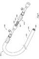
- FIG. 7is a perspective view of another illustrative stent delivery assembly.
- the stent delivery device and method for using the stent delivery device of the present inventionare believed to be applicable to a variety of applications where delivery of stents is desired, for example, atherosclerotic stent delivery. While the present invention is not so limited, an appreciation of various aspects of the invention will be gained through a discussion of the examples provided below.
- tubular members illustrated in the Figureshave generally circular cross sections, this is not a necessary part of the present invention, and the tubular members are merely shown as such for purposes of simplicity in illustration.
- FIG. 1Ais a schematic cross-sectional view of an illustrative stent delivery assembly 100 .
- the stent delivery assembly 100can include an elongate member 110 .
- the elongate member 110can be, for example, a catheter.
- the elongate member 110has a proximal region 112 and a distal region 114 . At least a portion of proximal region 112 can remain outside of a patient's vasculature. At least a portion of the distal region 114 can remain inside the patient's vasculature.
- the elongate member 110is any usable length such as, for example, 10 to 500 cm, 50 to 300 cm, or 75 to 200 cm.
- the elongate member 110can be formed of any material suitable for delivering a stent through tortuous vessel passages such as, for example, a polymer, a metal, or a combination thereof.
- Exemplary materialsinclude polyethylene, reinforced polyethylene, nylon, reinforced nylon, polyurethanes, reinforced polyurethanes, polyamides, or reinforced polyamides.
- a guidewire(not shown) can be optionally employed to guide the elongate member 110 distal region 114 to a target site within a patient's vasculature.
- the guidewirecan be within a portion of the elongate member 110 .
- the guidewirecan be any operable diameter such as, for example, 0.01 to 0.04 inch or 0.014 to 0.035 inch.
- the elongate member 110can have an outer tubular member 115 located at the distal region 114 .
- a self-expanding stent 120can be disposed within at least a portion of the outer tubular member 115 .
- the outer tubular member 115has an inner diameter sufficient in size to receive a compressed stent 120 .
- the outer tubular member 115can be formed of materials similar to those described above for forming the elongate member 110 .
- an optional inner layer 150 of lubricious materialcan be disposed between the stent 120 and outer tubular member 115 .
- the inner layer 150can be formed of polytetrafluoroethylene, for example.
- the outer tubular member 115can be any material as described above such as, for example, a clear medical grade PTFE (polytetrafluoroethylene) extrusion, which covers the distal 2-20 cm (depending on stent length) of the stent delivery device 100 .
- PTFEpolytetrafluoroethylene
- the outer tubular membercould be made of any suitable material as described above.
- a specific alternative embodimentcould utilize a fluoropolymer material which is substantially transparent to visible light to enable an operator to directly view deployment in an endoscopic delivery procedure.
- self-expanding nitinol stentsof from 1-15 mm or 6-14 mm in diameter and ranging from 1-100 mm or 5-50 mm in length can be accommodated.
- the self-expanding stent 120can be formed from any material such as, for example, nitinol or stainless steel.
- the stent 120can include one or more radiopaque markers for alignment into the target vessel.
- the stent 120can be compressed at a low temperature for loading into delivery system 100 and held in its reduced delivery configuration by the outer tubular member 115 .
- nitinolupon deployment in vivo at body temperature, the original stent shape can be restored as the nitinol stent self-expands, exerting radial force on the constricted portion of the body lumen to re-establish patency.
- the elongate member 110can include an inner elongate member 130 disposed within at least a portion of the elongate member 110 .
- the inner elongate member 130can be formed of a polymer, a metal, or a combination thereof, as described above.
- the inner elongate member 130can include a helical engagement element 140 on at least a portion of the inner elongate member 130 .
- the helical element 140can be a helical protrusion extending away from the outer surface 131 of the inner elongate member 130 , or the helical element 140 can be a helical channel formed into the outer surface 131 of the inner elongate member 130 .
- a helical engagement element 141can be on at least a portion of the elongate member 110 inner surface 116 .
- the helical engagement element 141can be a single protrusion extending away from the elongate member 110 inner surface 116 toward the inner elongate member 130 , or the helical engagement element 141 can be a continuous or non-continuous helical protrusion extending away from the elongate member 110 inner surface 116 toward the inner elongate member 130 .
- the elongate member 110can include a helical engagement element 140 on at least a portion of the elongate member 110 .
- the helical element 140can be a helical protrusion extending away from the inner surface 116 of the elongate member 110 , or the helical element 140 can be a helical channel formed into the inner surface 116 of the elongate member 110 .
- a helical engagement element 141can be on at least a portion of the inner elongate member 130 inner surface 131 .
- the helical engagement element 141can be a single protrusion extending away from the inner elongate member 130 outer surface 131 toward the elongate member 110 , or the helical engagement element 141 can be a continuous or non-continuous helical protrusion extending away from the inner elongate member 130 outer surface 131 toward the elongate member 110 .
- the helical engagement element 141is arranged and configured to engage the helical element 140 and convert at least a portion of circumferential movement T of the inner elongate member 130 into axial movement A D .
- rotational movement T of the inner elongate member 130forces the inner elongate member 130 against the self-expanding stent 120 and pushes the self-expanding stent 120 axially in a distal direction A D relative to the outer tubular member 115 , deploying the stent.
- FIG. 1Bis a schematic cross-sectional view of FIG. 1A with a stent 120 partially deployed.
- the inner elongate member 130 near the proximal region 112has been rotated about the longitudinal axis of the inner elongate member 130 , causing axial movement of the inner elongate member 130 relative to the elongate member 110 and outer tubular member 115 , moving the stent 120 in the distal direction A D .
- the inner elongate member 130can move along the longitudinal axis a distance sufficient to deploy the stent 120 .
- the inner elongate member 130can move along the longitudinal axis a distance at least equal to the length of the stent 120 .
- FIG. 2Ais a schematic cross-sectional view of another illustrative stent delivery assembly 200 .
- the stent delivery assembly 200can include an elongate member 210 .
- the elongate member 210can be, for example, a catheter.
- the elongate member 210has a proximal region 212 and a distal region 214 . At least a portion of proximal region 212 can remain outside of a patient's vasculature. At least a portion of the distal region 214 can remain inside the patient's vasculature.
- the elongate member 210is any usable length such as, for example, 10 to 500 cm, 50 to 300 cm, or 75 to 200 cm.
- the elongate member 210can be formed of any material suitable for delivering a stent through tortuous vessel passages such as, for example, a polymer, a metal, or a combination thereof.
- Exemplary materialsinclude polyethylene, reinforced polyethylene, nylon, reinforced nylon, polyurethanes, reinforced polyurethanes, polyamides, or reinforced polyamides.
- a guidewirecan be optionally employed to guide the elongate member 210 distal region 214 to a target site within a patient's vasculature.
- the guidewirecan be within a portion of the elongate member 210 .
- the guidewirecan be any operable diameter such as, for example, 0.01 to 0.04 inch or 0.014 to 0.035 inch.
- the elongate member 210can have an outer tubular member 215 located at the distal region 214 .
- a self-expanding stent 220can be disposed within at least a portion of the outer tubular member 215 .
- the outer tubular member 215has an inner diameter sufficient in size to receive a compressed stent 220 .
- the outer tubular member 215can be formed of materials similar those described above for forming the elongate member 210 .
- an optional inner layer 250 of lubricious materialcan be disposed between the stent 220 and outer tubular member 215 .
- the inner layer 250can be formed of polytetrafluoroethylene, for example.
- the outer tubular member 215can be any material as described above such as, for example, a clear medical grade PTFE (polytetrafluoroethylene) extrusion, which covers the distal 2-20 cm (depending on stent length) of the stent delivery device 200 .
- PTFEpolytetrafluoroethylene
- the outer tubular membercould be made of any suitable material as described above.
- a specific alternative embodimentcould utilize a fluoropolymer material which is substantially transparent to visible light to enable an operator to directly view deployment in an endoscopic delivery procedure. Such materials are known in the art.
- self-expanding nitinol stentsof from 1-15 mm or 6-14 mm in diameter and ranging from 1-100 mm or 5-50 mm in length can be accommodated.
- the self-expanding stent 220can be formed from any material such as, for example, nitinol or stainless steel.
- the stent 220can include one or more radiopaque markers for alignment into the target vessel.
- the stent 220can be compressed at a low temperature for loading into delivery system 200 and held in its reduced delivery configuration by the outer tubular member 215 .
- nitinolupon deployment in vivo at body temperature, the original stent shape can be restored as the nitinol stent self-expands, exerting radial force on the constricted portion of the body lumen to re-establish patency.
- the elongate member 210can include an inner elongate member 230 disposed within at least a portion of the elongate member 210 .
- the inner elongate member 230can be formed of a polymer, a metal, or a combination thereof, as described above.
- the inner elongate member 230can include a helical engagement element 240 on at least a portion of the inner elongate member 230 .
- the helical engagement element 240can be a helical protrusion extending away from the outer surface 231 of the inner elongate member 230 , or the helical engagement element 240 can be a helical channel formed into the outer surface 231 of the inner elongate member 230 .
- a helical engagement element 241can be on at least a portion of the elongate member 210 inner surface 216 .
- the helical engagement element 241can be a single protrusion extending away from the elongate member 210 inner surface 216 toward the inner elongate member 230 , or the helical engagement element 241 can be a continuous or non-continuous helical protrusion extending away from the elongate member 210 inner surface 216 toward the inner elongate member 230 .
- the elongate member 210can include a helical engagement element 240 on at least a portion of the elongate member 210 .
- the helical engagement element 240can be a helical protrusion extending away from the inner surface 216 of the elongate member 210 , or the helical engagement element 240 can be a helical channel formed into the inner surface 216 of the elongate member 210 .
- a helical engagement element 241can be on at least a portion of the inner elongate member 230 inner surface 231 .
- the helical engagement element 241can be a single protrusion extending away from the inner elongate member 230 outer surface 231 toward the elongate member 210 , or the helical engagement element 241 can be a continuous or non-continuous helical protrusion extending away from the inner elongate member 230 outer surface 231 toward the elongate member 210 .
- the helical engagement element 241is arranged and configured to engage the helical engagement element 240 and convert at least a portion of circumferential movement T of the elongate member 210 into axial movement A P .
- rotational movement T of the elongate member 210pulls the outer tubular member 215 axially in a proximal direction A P relative to the stent 220 , deploying the stent.
- FIG. 2Bis a schematic cross-sectional view of FIG. 2A with a stent 220 partially deployed.
- the elongate member 210 proximal region 212has been rotated about the longitudinal axis of the elongate member 210 , causing axial movement of the outer tubular member 215 and/or elongate member 210 relative to the stent 220 , moving the outer tubular member 215 in the proximal direction A P .
- the outer tubular member 215can move along the longitudinal axis a distance sufficient to deploy the stent 220 .
- the tubular member 215can move along the longitudinal axis a distance at least equal to the length of the stent 220 .
- FIG. 3Ais a schematic cross-sectional view of an illustrative stent delivery assembly 300 .
- the stent delivery assembly 300can include an elongate member 310 .
- the elongate member 310can be, for example, a catheter.
- the elongate member 310has a proximal region 312 and a distal region 314 . At least a portion of proximal region 312 can remain outside of a patient's vasculature. At least a portion of the distal region 314 can remain inside the patient's vasculature.
- the elongate member 310is any usable length such as, for example, 10 to 500 cm, 50 to 300 cm, or 75 to 200 cm.
- the elongate member 310can be formed of any material suitable for delivering a stent through tortuous vessel passages such as, for example, a polymer, a metal, or a combination thereof.
- Exemplary materialsinclude polyethylene, reinforced polyethylene, nylon, reinforced nylon, polyurethanes, reinforced polyurethanes, polyamides, or reinforced polyamides.
- a guidewirecan be optionally employed to guide the elongate member 310 distal region 314 to a target site within a patient's vasculature.
- the guidewirecan be within a portion of the elongate member 310 .
- the guidewirecan be any operable diameter such as, for example, 0.01 to 0.04 inch or 0.014 to 0.035 inch.
- the elongate member 310can have an outer tubular member 315 located at the distal region 314 .
- a self-expanding stent 320can be disposed within at least a portion of the outer tubular member 315 .
- the outer tubular member 315has an inner diameter sufficient in size to receive a compressed stent 320 .
- the outer tubular member 315can be formed of materials similar to those described above for forming the elongate member 310 .
- an optional inner layer 350 of lubricious materialcan be disposed between the stent 320 and outer tubular member 315 .
- the inner layer 350can be formed of polytetrafluoroethylene, for example.
- the outer tubular member 315can be any material as described above such as, for example, a clear medical grade PTFE (polytetrafluoroethylene) extrusion, which covers the distal 2-20 cm (depending on stent length) of the stent delivery device 300 .
- PTFEpolytetrafluoroethylene
- the outer tubular membercould be made of any suitable material as described above.
- a specific alternative embodimentcould utilize a fluoropolymer material which is substantially transparent to visible light to enable an operator to directly view deployment in an endoscopic delivery procedure. Such materials are known in the art.
- self-expanding nitinol stentsof from 1-15 mm or 6-14 mm in diameter and ranging from 1-100 mm or 5-50 mm in length can be accommodated.
- the self-expanding stent 320can be formed from any material such as, for example, nitinol or stainless steel.
- the stent 320can include one or more radiopaque markers for alignment into the target vessel.
- the stent 320can be compressed at a low temperature for loading into delivery system 300 and held in its reduced delivery configuration by the outer tubular member 315 .
- nitinolupon deployment in vivo at body temperature, the original stent shape can be restored as the nitinol stent self-expands, exerting radial force on the constricted portion of the body lumen to re-establish patency.
- the elongate member 310can include an inner elongate member 330 disposed within at least a portion of the elongate member 310 .
- the inner elongate member 330can be formed of a polymer, a metal, or a combination thereof, as described above.
- the inner elongate member 330can include a helical engagement element 340 on at least a portion of the inner elongate member 330 .
- the helical element 340can be a helical protrusion extending away from the outer surface 331 of the inner elongate member 330 , or the helical element 340 can be a helical channel formed into the outer surface 331 of the inner elongate member 330 .
- a helical engagement element 341can be on at least a portion of the elongate member 310 inner surface 316 .
- the helical engagement element 341can be a single protrusion extending away from the elongate member 310 inner surface 316 toward the inner elongate member 330 , or the helical engagement element 341 can be a continuous or non-continuous helical protrusion extending away from the elongate member 310 inner surface 316 toward the inner elongate member 330 .
- the elongate member 310can include a helical engagement element 340 on at least a portion of the elongate member 310 .
- the helical element 340can be a helical protrusion extending away from the inner surface 316 of the elongate member 310 , or the helical element 340 can be a helical channel formed into the inner surface 316 of the elongate member 310 .
- a helical engagement element 341can be on at least a portion of the inner elongate member 330 inner surface 331 .
- the helical engagement element 341can be a single protrusion extending away from the inner elongate member 330 outer surface 331 toward the elongate member 310 , or the helical engagement element 341 can be a continuous or non-continuous helical protrusion extending away from the inner elongate member 330 outer surface 331 toward the elongate member 310 .
- the helical engagement element 341is arranged and configured to engage the helical element 340 and convert at least a portion of circumferential movement T of the inner elongate member 330 into axial movement A P .
- rotational movement T of the inner elongate member 330pulls the outer tubular member 315 axially in a proximal direction A P relative to the stent 320 , exposing the stent 320 and deploying the stent 320 .
- FIG. 3Bis a schematic cross-sectional view of FIG. 3A with a stent 320 partially deployed.
- the elongate member 310 near the proximal region 312has been rotated about the longitudinal axis of the elongate member 330 , causing axial movement of the outer tubular member 315 relative to the stent 320 , moving the outer tubular member 315 in the proximal direction A P .
- the outer tubular member 315can move along the longitudinal axis a distance sufficient to deploy the stent 320 .
- the outer tubular member 315can move along the longitudinal axis a distance at least equal to the length of the stent 320 .
- FIG. 4Ais a schematic cross-sectional view of another illustrative stent delivery assembly 400 .
- the stent delivery assembly 400can include an elongate member 410 .
- the elongate member 410can be, for example, a catheter.
- the elongate member 410has a proximal region 412 and a distal region 414 . At least a portion of proximal region 412 can remain outside of a patient's vasculature. At least a portion of the distal region 414 can remain inside the patient's vasculature.
- the elongate member 410is any usable length such as, for example, 10 to 500 cm, 50 to 300 cm, or 75 to 200 cm.
- the elongate member 410can be formed of any material suitable for delivering a stent through tortuous vessel passages such as, for example, a polymer, a metal, or a combination thereof.
- Exemplary materialsinclude polyethylene, reinforced polyethylene, nylon, reinforced nylon, polyurethanes, reinforced polyurethanes, polyamides, or reinforced polyamides.
- a guidewirecan be optionally employed to guide the elongate member 410 distal region 414 to a target site within a patient's vasculature.
- the guidewirecan be within a portion of the elongate member 410 .
- the guidewirecan be any operable diameter such as, for example, 0.01 to 0.04 inch or 0.014 to 0.035 inch.
- the elongate member 410can have an outer tubular member 415 located at the distal region 414 .
- a self-expanding stent 420can be disposed within at least a portion of the outer tubular member 415 .
- the outer tubular member 415has an inner diameter sufficient in size to receive a compressed stent 420 .
- the outer tubular member 415can be formed of materials similar those described above for forming the elongate member 410 .
- an optional inner layer 450 of lubricious materialcan be disposed between the stent 420 and outer tubular member 415 .
- the inner layer 450can be formed of polytetrafluoroethylene, for example.
- the outer tubular member 415can be any material as described above such as, for example, a clear medical grade PTFE (polytetrafluoroethylene) extrusion, which covers the distal 2-20 cm (depending on stent length) of the stent delivery device 400 .
- the outer tubular membercould be made of any suitable material as described above.
- a specific alternative embodimentcould utilize a fluoropolymer material which is substantially transparent to visible light to enable an operator to directly view deployment in an endoscopic delivery procedure. Such materials are known in the art.
- self-expanding nitinol stentsof from 1-15 mm or 6-14 mm in diameter and ranging from 1-100 mm or 5-50 mm in length can be accommodated.
- the self-expanding stent 420can be formed from any material such as, for example, nitinol or stainless steel.
- the stent 420can include one or more radiopaque markers for alignment into the target vessel.
- the stent 420can be compressed at a low temperature for loading into delivery system 400 and held in its reduced delivery configuration by the outer tubular member 415 .
- nitinolupon deployment in vivo at body temperature, the original stent shape can be restored as the nitinol stent self-expands, exerting radial force on the constricted portion of the body lumen to re-establish patency.
- the elongate member 410can include an inner elongate member 430 disposed within at least a portion of the elongate member 410 .
- the inner elongate member 430can be formed of a polymer, a metal, or a combination thereof, as described above.
- the inner elongate member 430can include a helical engagement element 440 on at least a portion of the inner elongate member 430 .
- the helical element 440can be a helical protrusion extending away from the outer surface 431 of the inner elongate member 430 , or the helical element 440 can be a helical channel formed into the outer surface 431 of the inner elongate member 430 .
- a helical engagement element 441can be on at least a portion of the elongate member 410 inner surface 416 .
- the helical engagement element 441can be a single protrusion extending away from the elongate member 410 inner surface 416 toward the inner elongate member 430 , or the helical engagement element 441 can be a continuous or non-continuous helical protrusion extending away from the elongate member 410 inner surface 416 toward the inner elongate member 430 .
- the elongate member 410can include a helical engagement element 440 on at least a portion of the elongate member 410 .
- the helical element 440can be a helical protrusion extending away from the inner surface 416 of the elongate member 410 , or the helical element 440 can be a helical channel formed into the inner surface 416 of the elongate member 410 .
- a helical engagement element 441can be on at least a portion of the inner elongate member 430 inner surface 431 .
- the helical engagement element 441can be a single protrusion extending away from the inner elongate member 430 outer surface 431 toward the elongate member 410 , or the helical engagement element 441 can be a continuous or non-continuous helical protrusion extending away from the inner elongate member 430 outer surface 431 toward the elongate member 410 .
- the helical engagement element 441is arranged and configured to engage the helical element 440 and convert at least a portion of circumferential movement T of the inner elongate member 430 into axial movement A D .
- rotational movement T of the inner elongate member 430forces the stent 420 axially in a distal direction A D relative to the outer tubular member 415 , deploying the stent.
- FIG. 4Bis a schematic cross-sectional view of FIG. 4A with a stent 420 partially deployed.
- the inner elongate member 430 proximal region 412has been rotated about the longitudinal axis of the inner elongate member 430 , causing axial movement of the inner elongate member 430 and stent 420 relative to the outer tubular member 415 , moving the stent 420 in the distal direction A D .
- the inner tubular member 430can move along the longitudinal axis a distance sufficient to deploy the stent 420 .
- the inner tubular member 430can move along the longitudinal axis a distance at least equal to the length of the stent 420 .
- FIG. 5Ais a schematic cross-sectional view of an illustrative stent delivery assembly 500 .
- the stent delivery assembly 500can include an elongate member 510 .
- the elongate member 510can be, for example, a catheter.
- the elongate member 510has a proximal region 512 and a distal region 514 . At least a portion of proximal region 512 can remain outside of a patient's vasculature. At least a portion of the distal region 514 can remain inside the patient's vasculature.
- the elongate member 510is any usable length such as, for example, 10 to 500 cm, 50 to 300 cm, or 75 to 200 cm.
- the elongate member 510can be formed of any material suitable for delivering a stent through tortuous vessel passages such as, for example, a polymer, a metal, or a combination thereof.
- Exemplary materialsinclude polyethylene, reinforced polyethylene, nylon, reinforced nylon, polyurethanes, reinforced polyurethanes, polyamides, or reinforced polyamides.
- a guidewirecan be optionally employed to guide the elongate member 510 distal region 514 to a target site within a patient's vasculature.
- the guidewirecan be within a portion of the elongate member 510 .
- the guidewirecan be any operable diameter such as, for example, 0.01 to 0.04 inch or 0.014 to 0.035 inch.
- the elongate member 510can have an outer tubular member 515 located at the distal region 514 .
- a self-expanding stent 520can be disposed within at least a portion of the outer tubular member 515 .
- the outer tubular member 515has an inner diameter sufficient in size to receive a compressed stent 520 .
- the outer tubular member 515can be formed of materials similar those described above for forming the elongate member 510 .
- an optional inner layer 550 of lubricious materialcan be disposed between the stent 520 and outer tubular member 515 .
- the inner layer 550can be formed of polytetrafluoroethylene, for example.
- the outer tubular member 515can be any material as described above such as, for example, a clear medical grade PTFE (polytetrafluoroethylene) extrusion, which covers the distal 2-20 cm (depending on stent length) of the stent delivery device 500 .
- the outer tubular membercould be made of any suitable material as described above.
- a specific alternative embodimentcould utilize a fluoropolymer material which is substantially transparent to visible light to enable an operator to directly view deployment in an endoscopic delivery procedure. Such materials are known in the art.
- self-expanding nitinol stentsof from 1-15 mm or 6-14 mm in diameter and ranging from 1-100 mm or 5-50 mm in length can be accommodated.
- the self-expanding stent 520can be formed from any material such as, for example, nitinol or stainless steel.
- the stent 520can include one or more radiopaque markers for alignment into the target vessel.
- the stent 520can be compressed at a low temperature for loading into delivery system 500 and held in its reduced delivery configuration by the outer tubular member 515 .
- nitinolupon deployment in vivo at body temperature, the original stent shape can be restored as the nitinol stent self-expands, exerting radial force on the constricted portion of the body lumen to re-establish patency.
- the elongate member 510can include an inner elongate member 530 disposed within at least a portion of the elongate member 510 .
- the inner elongate member 530can be formed of a polymer, a metal, or a combination thereof, as described above.
- the inner elongate member 530can include a helical engagement element 541 on at least a portion of the inner elongate member 530 .
- the helical engagement element 541can be a helical protrusion extending away from the outer surface 531 of the inner elongate member 530 .
- An intermediate tubular member 535can be disposed between the inner tubular member 530 and the elongate member 510 .
- the intermediate tubular member 535can be formed of any material described above.
- the intermediate tubular membercan be a hypotube.
- a helical element 540can be on at least a portion of the intermediate tubular member 535 .
- the helical element 540can be a continuous or non-continuous helical protrusion or channel.
- the intermediate tubular member 535can include a helical element 540 on at least a portion of the intermediate tubular member 535 .
- the helical element 540can be a helical protrusion extending away from the inner surface of the intermediate tubular member 535 , or the helical element 540 can be a helical channel formed into the tubular member 535 .
- a helical engagement element 541can be on at least a portion of the inner elongate member 530 inner surface 531 .
- the helical engagement element 541can be a single protrusion extending away from the inner elongate member 530 outer surface 531 toward the intermediate tubular member 535 , or the helical engagement element 541 can be a continuous or non-continuous helical protrusion extending away from the inner elongate member 530 outer surface 531 toward the intermediate tubular member 535 .
- the helical engagement element 541is arranged and configured to engage the helical element 540 and convert at least a portion of circumferential movement T of the inner elongate member 530 into axial movement A D .
- the inner elongate member 530acts as a torque plunger when advanced.
- rotational movement T of the inner elongate member 530forces the inner elongate member 530 and/or the intermediate tubular member 535 against the self-expanding stent 520 and pushes the self-expanding stent 520 axially in a distal direction A D relative to the outer tubular member 515 , deploying the stent.
- FIG. 5Bis a schematic cross-sectional view of FIG. 5A with a stent 520 partially deployed.
- the inner elongate member 530 near the proximal region 512has been rotated about the longitudinal axis of the inner elongate member 530 , causing axial movement of the inner elongate member 530 and/or intermediate tubular member 535 relative to the elongate member 510 and outer tubular member 515 , moving the stent 520 in the distal direction A D .
- the inner elongate member 530 and/or intermediate tubular member 535can move along the longitudinal axis a distance sufficient to deploy the stent 520 .
- the inner elongate member 530 and/or intermediate tubular member 535can move along the longitudinal axis a distance at least equal to the length of the stent 520 .
- a usercan carefully control the advancement or deployment of the stent 520 onto the target site.
- FIG. 6is a perspective view of an illustrative stent delivery 600 assembly.
- the stent delivery assembly 600can include an elongate member 610 .
- the elongate member 610can be, for example, a catheter.
- the elongate member 610has a proximal region 612 and a distal region 614 . At least a portion of proximal region 612 can remain outside of a patient's vasculature. At least a portion of the distal region 614 can remain inside the patient's vasculature.
- the elongate member 610is any usable length such as, for example, 10 to 500 cm, 50 to 300 cm, or 75 to 200 cm.
- the elongate member 610can be formed of any material suitable for delivering a stent through tortuous vessel passages such as, for example, a polymer, a metal, or a combination thereof.
- Exemplary materialsinclude polyethylene, reinforced polyethylene, nylon, reinforced nylon, polyurethanes, reinforced polyurethanes, polyamides, or reinforced polyamides.
- the elongate member 610can have an outer tubular member 615 located at the distal region 614 .
- a self-expanding stent 620can be disposed within at least a portion of the outer tubular member 615 .
- the outer tubular member 615has an inner diameter sufficient in size to receive a compressed stent 620 .
- the outer tubular member 615can be formed of materials similar those described above for forming the elongate member 610 .
- the outer tubular member 615can be any material as described above such as, for example, a clear medical grade PTFE (polytetrafluoroethylene) extrusion, which covers the distal 2-20 cm (depending on stent length) of the stent delivery device 600 .
- PTFEpolytetrafluoroethylene
- the outer tubular membercould be made of any suitable material as described above.
- self-expanding nitinol stentsof from 1-15 mm or 6-14 mm in diameter and ranging from 1-100 mm or 5-50 mm in length can be accommodated.
- the self-expanding stent 620can be formed from any material such as, for example, nitinol or stainless steel.
- the stent 620can include one or more radiopaque markers for alignment into the target vessel.
- the stent 620can be compressed at a low temperature for loading into delivery system 600 and held in its reduced delivery configuration by the outer tubular member 615 .
- nitinolupon deployment in vivo at body temperature, the original stent shape can be restored as the nitinol stent self-expands, exerting radial force on the constricted portion of the body lumen to re-establish patency.
- the elongate member 610can include an inner elongate member 630 disposed within at least a portion of the elongate member 610 .
- the inner elongate member 630can be formed of a polymer, a metal, or a combination thereof, as described above.
- the inner elongate member 630can include a helical engagement element 641 on at least a portion of the inner elongate member 630 .
- the helical engagement element 641can be a helical protrusion extending away from the outer surface 631 of the inner elongate member 630 .
- the helical engagement element 641is disposed on the proximal end 612 of the inner elongate member 630 .
- the helical engagement element 641may be located on any position along the inner elongate member 630 .
- the helical engagement element 641is arranged and configured to engage the helical element 640 and convert at least a portion of circumferential movement of the inner elongate member 630 into axial movement.
- rotational movement of the inner elongate member 630pulls the outer tubular member in a proximal direction relative to the inner elongate member 630 , deploying the stent as described in FIGS. 2 and 3 above.
- FIG. 7is a perspective view of another illustrative stent delivery 700 assembly.
- the elongate member 710can be, for example, a catheter.
- the elongate member 710has a proximal region 712 and a distal region 714 . At least a portion of proximal region 712 can remain outside of a patient's vasculature. At least a portion of the distal region 714 can remain inside the patient's vasculature.
- the elongate member 710is any usable length such as, for example, 10 to 500 cm, 50 to 300 cm, or 75 to 200 cm.
- the elongate member 710can be formed of any material suitable for delivering a stent through tortuous vessel passages such as, for example, a polymer, a metal, or a combination thereof.
- Exemplary materialsinclude polyethylene, reinforced polyethylene, nylon, reinforced nylon, polyurethanes, reinforced polyurethanes, polyamides, or reinforced polyamides.
- the elongate member 710can have an outer tubular member 715 located at the distal region 714 .
- a self-expanding stent 720can be disposed within at least a portion of the outer tubular member 715 .
- the outer tubular member 715has an inner diameter sufficient in size to receive a compressed stent 720 .
- the outer tubular member 715can be formed of materials similar those described above for forming the elongate member 710 .
- the outer tubular member 715can be any material as described above such as, for example, a clear medical grade PTFE (polytetrafluoroethylene) extrusion, which covers the distal 2-20 cm (depending on stent length) of the stent delivery device 700 .
- PTFEpolytetrafluoroethylene
- the outer tubular membercould be made of any suitable material as described above.
- self-expanding nitinol stentsof from 1-15 mm or 6-14 mm in diameter and ranging from 1-100 mm or 5-50 mm in length can be accommodated.
- the self-expanding stent 720can be formed from any material such as, for example, nitinol or stainless steel.
- the stent 720can include one or more radiopaque markers for alignment into the target vessel.
- the stent 720can be compressed at a low temperature for loading into delivery system 700 and held in its reduced delivery configuration by the outer tubular member 715 .
- nitinolupon deployment in vivo at body temperature, the original stent shape can be restored as the nitinol stent self-expands, exerting radial force on the constricted portion of the body lumen to re-establish patency.
- the elongate member 710can include an inner elongate member 730 disposed within at least a portion of the elongate member 710 .
- the inner elongate member 730can be formed of a polymer, a metal, or a combination thereof, as described above.
- the inner elongate member 730can include a helical engagement element 741 on at least a portion of the inner elongate member 730 (shown on FIG. via cutaway window).
- the helical engagement element 741can be a helical protrusion extending away from the outer surface 731 of the inner elongate member 730 .
- the helical engagement element 741is arranged and configured to engage the helical element 740 and convert at least a portion of circumferential movement of the inner elongate member 730 into axial movement.
- rotational movement of the inner elongate member 730forces the inner elongate member 730 against the self-expanding stent 720 and pushes the self-expanding stent 720 axially in a distal direction relative to the outer tubular member 715 , deploying the stent, as described above.
Landscapes
- Health & Medical Sciences (AREA)
- Engineering & Computer Science (AREA)
- Biomedical Technology (AREA)
- Cardiology (AREA)
- Oral & Maxillofacial Surgery (AREA)
- Transplantation (AREA)
- Heart & Thoracic Surgery (AREA)
- Vascular Medicine (AREA)
- Life Sciences & Earth Sciences (AREA)
- Animal Behavior & Ethology (AREA)
- General Health & Medical Sciences (AREA)
- Public Health (AREA)
- Veterinary Medicine (AREA)
- Media Introduction/Drainage Providing Device (AREA)
Abstract
Description
Claims (9)
Priority Applications (5)
| Application Number | Priority Date | Filing Date | Title |
|---|---|---|---|
| US10/746,516US7887574B2 (en) | 2003-12-23 | 2003-12-23 | Stent delivery catheter |
| PCT/US2004/041534WO2005065586A1 (en) | 2003-12-23 | 2004-12-09 | Stent delivery catheter |
| EP04813798AEP1708646A1 (en) | 2003-12-23 | 2004-12-09 | Stent delivery catheter |
| JP2006547088AJP2007516040A (en) | 2003-12-23 | 2004-12-09 | Stent delivery catheter |
| CA002550681ACA2550681A1 (en) | 2003-12-23 | 2004-12-09 | Stent delivery catheter |
Applications Claiming Priority (1)
| Application Number | Priority Date | Filing Date | Title |
|---|---|---|---|
| US10/746,516US7887574B2 (en) | 2003-12-23 | 2003-12-23 | Stent delivery catheter |
Publications (2)
| Publication Number | Publication Date |
|---|---|
| US20050149160A1 US20050149160A1 (en) | 2005-07-07 |
| US7887574B2true US7887574B2 (en) | 2011-02-15 |
Family
ID=34710701
Family Applications (1)
| Application Number | Title | Priority Date | Filing Date |
|---|---|---|---|
| US10/746,516Active2026-08-18US7887574B2 (en) | 2003-12-23 | 2003-12-23 | Stent delivery catheter |
Country Status (5)
| Country | Link |
|---|---|
| US (1) | US7887574B2 (en) |
| EP (1) | EP1708646A1 (en) |
| JP (1) | JP2007516040A (en) |
| CA (1) | CA2550681A1 (en) |
| WO (1) | WO2005065586A1 (en) |
Cited By (8)
| Publication number | Priority date | Publication date | Assignee | Title |
|---|---|---|---|---|
| US20060259114A1 (en)* | 2005-05-13 | 2006-11-16 | Debbie Breyer | Endoprosthesis delivery system |
| US8419788B2 (en) | 2006-10-22 | 2013-04-16 | Idev Technologies, Inc. | Secured strand end devices |
| US8974516B2 (en) | 1999-02-01 | 2015-03-10 | Board Of Regents, The University Of Texas System | Plain woven stents |
| US9023095B2 (en) | 2010-05-27 | 2015-05-05 | Idev Technologies, Inc. | Stent delivery system with pusher assembly |
| US20190046229A1 (en)* | 2016-02-22 | 2019-02-14 | Capsos Medical Limited | A device and a method for guiding a boring tool, a guide wire or an instrument into engagement with an occlusion in a vessel or a wall of the vessel in the body of a human or animal subject |
| US10881542B2 (en) | 2016-04-05 | 2021-01-05 | Boston Scientific Scimed, Inc. | Stent delivery device |
| US20220346994A1 (en)* | 2021-03-04 | 2022-11-03 | Aquedeon Medical, Inc. | Vascular and aortic connectors with robotic delivery and deployment methods thereof |
| US11744692B2 (en) | 2017-02-23 | 2023-09-05 | Boston Scientific Scimed, Inc. | Medical drain device |
Families Citing this family (109)
| Publication number | Priority date | Publication date | Assignee | Title |
|---|---|---|---|---|
| US6454799B1 (en) | 2000-04-06 | 2002-09-24 | Edwards Lifesciences Corporation | Minimally-invasive heart valves and methods of use |
| US6733525B2 (en) | 2001-03-23 | 2004-05-11 | Edwards Lifesciences Corporation | Rolled minimally-invasive heart valves and methods of use |
| US6893460B2 (en) | 2001-10-11 | 2005-05-17 | Percutaneous Valve Technologies Inc. | Implantable prosthetic valve |
| EP1701675B1 (en)* | 2004-01-08 | 2010-07-14 | Merit Medical Systems, Inc. | Implantable device delivery system handle and method of use |
| US7731654B2 (en)* | 2005-05-13 | 2010-06-08 | Merit Medical Systems, Inc. | Delivery device with viewing window and associated method |
| EP1895951A1 (en)* | 2005-05-13 | 2008-03-12 | Alveolus Inc. | Delivery device allowing visual inspection of an intravascular site |
| US7780723B2 (en) | 2005-06-13 | 2010-08-24 | Edwards Lifesciences Corporation | Heart valve delivery system |
| KR101659197B1 (en) | 2006-10-22 | 2016-09-22 | 이데브 테크놀로지스, 아이엔씨. | Devices and methods for stent advancement |
| US8236045B2 (en) | 2006-12-22 | 2012-08-07 | Edwards Lifesciences Corporation | Implantable prosthetic valve assembly and method of making the same |
| JP2008194250A (en)* | 2007-02-14 | 2008-08-28 | Piolax Medical Device:Kk | Delivery tool of tubular organ treatment instrument |
| US20100222862A1 (en)* | 2007-09-06 | 2010-09-02 | Cook Incorporated | Stent, Stent Graft and Other Implantable Assemblies |
| US9061119B2 (en)* | 2008-05-09 | 2015-06-23 | Edwards Lifesciences Corporation | Low profile delivery system for transcatheter heart valve |
| US8323335B2 (en) | 2008-06-20 | 2012-12-04 | Edwards Lifesciences Corporation | Retaining mechanisms for prosthetic valves and methods for using |
| EP2313032B1 (en)* | 2008-08-19 | 2020-12-23 | Merit Medical Systems, Inc. | Delivery device with a protective member |
| US8652202B2 (en) | 2008-08-22 | 2014-02-18 | Edwards Lifesciences Corporation | Prosthetic heart valve and delivery apparatus |
| US20100125323A1 (en)* | 2008-11-14 | 2010-05-20 | Medtronic Vascular, Inc. | Coil Stent Delivery System and Method of Use |
| US8870950B2 (en) | 2009-12-08 | 2014-10-28 | Mitral Tech Ltd. | Rotation-based anchoring of an implant |
| US20110224785A1 (en) | 2010-03-10 | 2011-09-15 | Hacohen Gil | Prosthetic mitral valve with tissue anchors |
| US10751206B2 (en) | 2010-06-26 | 2020-08-25 | Scott M. Epstein | Catheter or stent delivery system |
| US20110319902A1 (en)* | 2010-06-26 | 2011-12-29 | Scott Epstein | Catheter delivery system |
| US9763657B2 (en) | 2010-07-21 | 2017-09-19 | Mitraltech Ltd. | Techniques for percutaneous mitral valve replacement and sealing |
| US11653910B2 (en) | 2010-07-21 | 2023-05-23 | Cardiovalve Ltd. | Helical anchor implantation |
| EP2648654B1 (en) | 2010-12-07 | 2024-02-14 | Merit Medical Systems, Inc. | Stent delivery systems |
| US9486348B2 (en)* | 2011-02-01 | 2016-11-08 | S. Jude Medical, Cardiology Division, Inc. | Vascular delivery system and method |
| US9155619B2 (en) | 2011-02-25 | 2015-10-13 | Edwards Lifesciences Corporation | Prosthetic heart valve delivery apparatus |
| EP2688525B1 (en) | 2011-03-23 | 2019-08-21 | Daidalos Solutions B.V. | Medical instrument, ring prosthesis, stent and stented valve |
| EP2739214B1 (en) | 2011-08-05 | 2018-10-10 | Cardiovalve Ltd | Percutaneous mitral valve replacement and sealing |
| US8852272B2 (en) | 2011-08-05 | 2014-10-07 | Mitraltech Ltd. | Techniques for percutaneous mitral valve replacement and sealing |
| WO2013021374A2 (en) | 2011-08-05 | 2013-02-14 | Mitraltech Ltd. | Techniques for percutaneous mitral valve replacement and sealing |
| US9192496B2 (en) | 2011-10-31 | 2015-11-24 | Merit Medical Systems, Inc. | Systems and methods for sheathing an implantable device |
| US9072624B2 (en) | 2012-02-23 | 2015-07-07 | Covidien Lp | Luminal stenting |
| EP2846742B1 (en)* | 2012-05-10 | 2024-07-03 | Biotronik AG | Device having a unit for positioning a prosthetic component |
| US20150351906A1 (en) | 2013-01-24 | 2015-12-10 | Mitraltech Ltd. | Ventricularly-anchored prosthetic valves |
| US9168129B2 (en) | 2013-02-12 | 2015-10-27 | Edwards Lifesciences Corporation | Artificial heart valve with scalloped frame design |
| US9827121B2 (en)* | 2013-03-15 | 2017-11-28 | Cook Medical Technologies Llc | Quick release deployment handle for medical devices |
| EP2999436B1 (en) | 2013-05-20 | 2018-08-29 | Edwards Lifesciences Corporation | Prosthetic heart valve delivery apparatus |
| US9545325B2 (en)* | 2013-08-08 | 2017-01-17 | Covidien Lp | Medical device delivery control mechanism |
| US10045867B2 (en) | 2013-08-27 | 2018-08-14 | Covidien Lp | Delivery of medical devices |
| US9782186B2 (en) | 2013-08-27 | 2017-10-10 | Covidien Lp | Vascular intervention system |
| US9622863B2 (en) | 2013-11-22 | 2017-04-18 | Edwards Lifesciences Corporation | Aortic insufficiency repair device and method |
| US10098734B2 (en) | 2013-12-05 | 2018-10-16 | Edwards Lifesciences Corporation | Prosthetic heart valve and delivery apparatus |
| EP3174502B1 (en) | 2014-07-30 | 2022-04-06 | Cardiovalve Ltd | Apparatus for implantation of an articulatable prosthetic valve |
| CN110141399B (en) | 2015-02-05 | 2021-07-27 | 卡迪尔维尔福股份有限公司 | Prosthetic valve with axial sliding frame |
| WO2016141295A1 (en) | 2015-03-05 | 2016-09-09 | Merit Medical Systems, Inc. | Vascular prosthesis deployment device and method of use |
| US10179046B2 (en) | 2015-08-14 | 2019-01-15 | Edwards Lifesciences Corporation | Gripping and pushing device for medical instrument |
| US10470906B2 (en) | 2015-09-15 | 2019-11-12 | Merit Medical Systems, Inc. | Implantable device delivery system |
| US10561496B2 (en) | 2015-09-16 | 2020-02-18 | Edwards Lifesciences Corporation | Perfusion balloon designs |
| US10350067B2 (en) | 2015-10-26 | 2019-07-16 | Edwards Lifesciences Corporation | Implant delivery capsule |
| US10321996B2 (en) | 2015-11-11 | 2019-06-18 | Edwards Lifesciences Corporation | Prosthetic valve delivery apparatus having clutch mechanism |
| WO2017087675A1 (en) | 2015-11-20 | 2017-05-26 | Cardiac Pacemakers, Inc. | Delivery devices and methods for leadless cardiac devices |
| AU2016355676B2 (en) | 2015-11-20 | 2018-12-13 | Cardiac Pacemakers, Inc. | Delivery devices and methods for leadless cardiac devices |
| US11033387B2 (en) | 2015-11-23 | 2021-06-15 | Edwards Lifesciences Corporation | Methods for controlled heart valve delivery |
| US10265169B2 (en) | 2015-11-23 | 2019-04-23 | Edwards Lifesciences Corporation | Apparatus for controlled heart valve delivery |
| US10531866B2 (en) | 2016-02-16 | 2020-01-14 | Cardiovalve Ltd. | Techniques for providing a replacement valve and transseptal communication |
| US10799677B2 (en) | 2016-03-21 | 2020-10-13 | Edwards Lifesciences Corporation | Multi-direction steerable handles for steering catheters |
| US10799676B2 (en) | 2016-03-21 | 2020-10-13 | Edwards Lifesciences Corporation | Multi-direction steerable handles for steering catheters |
| US11219746B2 (en) | 2016-03-21 | 2022-01-11 | Edwards Lifesciences Corporation | Multi-direction steerable handles for steering catheters |
| US20190231525A1 (en) | 2016-08-01 | 2019-08-01 | Mitraltech Ltd. | Minimally-invasive delivery systems |
| CA3031187A1 (en) | 2016-08-10 | 2018-02-15 | Cardiovalve Ltd. | Prosthetic valve with concentric frames |
| CN115054413A (en) | 2016-09-29 | 2022-09-16 | 美国医疗设备有限公司 | Method of adjusting effective length of stent and prosthesis delivery catheter assembly |
| CA3047396A1 (en) | 2016-12-20 | 2018-06-28 | Edwards Lifesciences Corporation | Systems and mechanisms for deploying a docking device for a replacement heart valve |
| US10376396B2 (en) | 2017-01-19 | 2019-08-13 | Covidien Lp | Coupling units for medical device delivery systems |
| EP4467111A3 (en) | 2017-03-15 | 2025-03-05 | Merit Medical Systems, Inc. | Transluminal stents |
| US11628078B2 (en) | 2017-03-15 | 2023-04-18 | Merit Medical Systems, Inc. | Transluminal delivery devices and related kits and methods |
| USD836194S1 (en) | 2017-03-21 | 2018-12-18 | Merit Medical Systems, Inc. | Stent deployment device |
| EP4613214A2 (en) | 2017-04-18 | 2025-09-10 | Edwards Lifesciences Corporation | Heart valve sealing devices and delivery devices therefor |
| US11224511B2 (en) | 2017-04-18 | 2022-01-18 | Edwards Lifesciences Corporation | Heart valve sealing devices and delivery devices therefor |
| US10973634B2 (en) | 2017-04-26 | 2021-04-13 | Edwards Lifesciences Corporation | Delivery apparatus for a prosthetic heart valve |
| US10959846B2 (en) | 2017-05-10 | 2021-03-30 | Edwards Lifesciences Corporation | Mitral valve spacer device |
| US10842619B2 (en) | 2017-05-12 | 2020-11-24 | Edwards Lifesciences Corporation | Prosthetic heart valve docking assembly |
| EP4397285A3 (en) | 2017-06-30 | 2024-09-25 | Edwards Lifesciences Corporation | Lock and release mechanisms for trans-catheter implantable devices |
| CN116196149A (en) | 2017-06-30 | 2023-06-02 | 爱德华兹生命科学公司 | Transcatheter valve docking station |
| US10857334B2 (en) | 2017-07-12 | 2020-12-08 | Edwards Lifesciences Corporation | Reduced operation force inflator |
| US10537426B2 (en) | 2017-08-03 | 2020-01-21 | Cardiovalve Ltd. | Prosthetic heart valve |
| US11793633B2 (en) | 2017-08-03 | 2023-10-24 | Cardiovalve Ltd. | Prosthetic heart valve |
| US12064347B2 (en) | 2017-08-03 | 2024-08-20 | Cardiovalve Ltd. | Prosthetic heart valve |
| US10888421B2 (en) | 2017-09-19 | 2021-01-12 | Cardiovalve Ltd. | Prosthetic heart valve with pouch |
| US11246704B2 (en) | 2017-08-03 | 2022-02-15 | Cardiovalve Ltd. | Prosthetic heart valve |
| US10575948B2 (en) | 2017-08-03 | 2020-03-03 | Cardiovalve Ltd. | Prosthetic heart valve |
| US10806573B2 (en) | 2017-08-22 | 2020-10-20 | Edwards Lifesciences Corporation | Gear drive mechanism for heart valve delivery apparatus |
| US11051939B2 (en) | 2017-08-31 | 2021-07-06 | Edwards Lifesciences Corporation | Active introducer sheath system |
| IL316784A (en) | 2017-10-18 | 2025-01-01 | Edwards Lifesciences Corp | Catheter assembly |
| US11207499B2 (en) | 2017-10-20 | 2021-12-28 | Edwards Lifesciences Corporation | Steerable catheter |
| GB201720803D0 (en) | 2017-12-13 | 2018-01-24 | Mitraltech Ltd | Prosthetic Valve and delivery tool therefor |
| GB201800399D0 (en) | 2018-01-10 | 2018-02-21 | Mitraltech Ltd | Temperature-control during crimping of an implant |
| US10786377B2 (en) | 2018-04-12 | 2020-09-29 | Covidien Lp | Medical device delivery |
| US11123209B2 (en) | 2018-04-12 | 2021-09-21 | Covidien Lp | Medical device delivery |
| US11071637B2 (en) | 2018-04-12 | 2021-07-27 | Covidien Lp | Medical device delivery |
| US11413176B2 (en) | 2018-04-12 | 2022-08-16 | Covidien Lp | Medical device delivery |
| PT3787561T (en) | 2018-04-30 | 2022-05-27 | Edwards Lifesciences Corp | DEVICES FOR CRIMPING PROSTHETIC IMPLANTS |
| CN116269937A (en) | 2018-04-30 | 2023-06-23 | 爱德华兹生命科学公司 | Push-on sheath style |
| US10441449B1 (en) | 2018-05-30 | 2019-10-15 | Vesper Medical, Inc. | Rotary handle stent delivery system and method |
| US11844914B2 (en) | 2018-06-05 | 2023-12-19 | Edwards Lifesciences Corporation | Removable volume indicator for syringe |
| US10449073B1 (en) | 2018-09-18 | 2019-10-22 | Vesper Medical, Inc. | Rotary handle stent delivery system and method |
| US11779728B2 (en) | 2018-11-01 | 2023-10-10 | Edwards Lifesciences Corporation | Introducer sheath with expandable introducer |
| JP7502298B2 (en) | 2018-12-11 | 2024-06-18 | エドワーズ ライフサイエンシーズ コーポレイション | Delivery system for prosthetic heart valves - Patents.com |
| WO2020123281A1 (en) | 2018-12-12 | 2020-06-18 | Edwards Lifesciences Corporation | Combined introducer and expandable sheath |
| SG11202107448UA (en) | 2019-01-16 | 2021-08-30 | Edwards Lifesciences Corp | Apparatus and method for monitoring valve expansion |
| US11413174B2 (en) | 2019-06-26 | 2022-08-16 | Covidien Lp | Core assembly for medical device delivery systems |
| US11219541B2 (en) | 2020-05-21 | 2022-01-11 | Vesper Medical, Inc. | Wheel lock for thumbwheel actuated device |
| EP4185239A4 (en) | 2020-07-24 | 2024-08-07 | Merit Medical Systems, Inc. | ESOPHAGEAL STENT PROSTHESES AND RELATED METHODS |
| EP4487822A3 (en) | 2020-08-24 | 2025-04-09 | Edwards Lifesciences Corporation | Commissure marker for a prosthetic heart valve |
| PL4203851T3 (en) | 2020-08-31 | 2025-06-23 | Edwards Lifesciences Corporation | Systems and methods for crimping and device preparation |
| CA3194910A1 (en) | 2020-10-26 | 2022-05-05 | Tiffany ETHRIDGE | Esophageal stents with helical thread |
| US12357459B2 (en) | 2020-12-03 | 2025-07-15 | Cardiovalve Ltd. | Transluminal delivery system |
| US12042413B2 (en) | 2021-04-07 | 2024-07-23 | Covidien Lp | Delivery of medical devices |
| US12109137B2 (en) | 2021-07-30 | 2024-10-08 | Covidien Lp | Medical device delivery |
| US11944558B2 (en) | 2021-08-05 | 2024-04-02 | Covidien Lp | Medical device delivery devices, systems, and methods |
| USD1084324S1 (en) | 2023-08-01 | 2025-07-15 | Edwards Lifesciences Corporation | Handle for implant delivery device |
Citations (86)
| Publication number | Priority date | Publication date | Assignee | Title |
|---|---|---|---|---|
| US4547194A (en) | 1984-03-16 | 1985-10-15 | Moorehead Harvey R | Hub assemblies and extensions for indwelling catheter tubes and method |
| US4572186A (en) | 1983-12-07 | 1986-02-25 | Cordis Corporation | Vessel dilation |
| US4655771A (en) | 1982-04-30 | 1987-04-07 | Shepherd Patents S.A. | Prosthesis comprising an expansible or contractile tubular body |
| US4732152A (en) | 1984-12-05 | 1988-03-22 | Medinvent S.A. | Device for implantation and a method of implantation in a vessel using such device |
| US4848343A (en) | 1986-10-31 | 1989-07-18 | Medinvent S.A. | Device for transluminal implantation |
| US4990151A (en) | 1988-09-28 | 1991-02-05 | Medinvent S.A. | Device for transluminal implantation or extraction |
| US5026377A (en) | 1989-07-13 | 1991-06-25 | American Medical Systems, Inc. | Stent placement instrument and method |
| US5089006A (en)* | 1989-11-29 | 1992-02-18 | Stiles Frank B | Biological duct liner and installation catheter |
| US5129887A (en) | 1988-12-07 | 1992-07-14 | Scimed Life Systems, Inc. | Adjustable manifold for dilatation catheter |
| EP0505686A1 (en) | 1991-01-28 | 1992-09-30 | Advanced Cardiovascular Systems, Inc. | Stent delivery system |
| US5192297A (en)* | 1991-12-31 | 1993-03-09 | Medtronic, Inc. | Apparatus and method for placement and implantation of a stent |
| US5201757A (en) | 1992-04-03 | 1993-04-13 | Schneider (Usa) Inc. | Medial region deployment of radially self-expanding stents |
| US5290248A (en) | 1989-07-24 | 1994-03-01 | Steven F. Bierman | Sideport connector for catherization system |
| US5324269A (en) | 1991-09-19 | 1994-06-28 | Baxter International Inc. | Fully exchangeable dual lumen over-the-wire dilatation catheter with rip seam |
| US5360401A (en) | 1993-02-18 | 1994-11-01 | Advanced Cardiovascular Systems, Inc. | Catheter for stent delivery |
| US5389087A (en) | 1991-09-19 | 1995-02-14 | Baxter International Inc. | Fully exchangeable over-the-wire catheter with rip seam and gated side port |
| US5391172A (en) | 1993-05-24 | 1995-02-21 | Advanced Cardiovascular Systems, Inc. | Stent delivery system with coaxial catheter handle |
| US5409495A (en) | 1993-08-24 | 1995-04-25 | Advanced Cardiovascular Systems, Inc. | Apparatus for uniformly implanting a stent |
| US5433723A (en)* | 1991-10-11 | 1995-07-18 | Angiomed Ag | Apparatus for widening a stenosis |
| US5458605A (en) | 1994-04-04 | 1995-10-17 | Advanced Cardiovascular Systems, Inc. | Coiled reinforced retractable sleeve for stent delivery catheter |
| US5458615A (en) | 1993-07-06 | 1995-10-17 | Advanced Cardiovascular Systems, Inc. | Stent delivery system |
| US5484444A (en) | 1992-10-31 | 1996-01-16 | Schneider (Europe) A.G. | Device for the implantation of self-expanding endoprostheses |
| US5533968A (en) | 1991-05-15 | 1996-07-09 | Advanced Cardiovascular Systems, Inc. | Low profile catheter with expandable outer tubular member |
| US5534007A (en) | 1995-05-18 | 1996-07-09 | Scimed Life Systems, Inc. | Stent deployment catheter with collapsible sheath |
| US5558101A (en) | 1994-10-14 | 1996-09-24 | Advanced Cardiovascular System, Inc. | Method and system for holding the position of a guiding member |
| US5571168A (en) | 1995-04-05 | 1996-11-05 | Scimed Lifesystems Inc | Pull back stent delivery system |
| US5579780A (en) | 1994-10-11 | 1996-12-03 | Zadini; Filiberto P. | Manual guidewire placement device |
| US5591172A (en) | 1991-06-14 | 1997-01-07 | Ams Medinvent S.A. | Transluminal implantation device |
| US5690645A (en) | 1995-06-28 | 1997-11-25 | Cordis Corporation | Device for moving a catheter in a controlled manner |
| US5690644A (en)* | 1992-12-30 | 1997-11-25 | Schneider (Usa) Inc. | Apparatus for deploying body implantable stent |
| US5695499A (en)* | 1994-10-27 | 1997-12-09 | Schneider (Usa) Inc. | Medical device supported by spirally wound wire |
| US5709703A (en) | 1995-11-14 | 1998-01-20 | Schneider (Europe) A.G. | Stent delivery device and method for manufacturing same |
| WO1998011846A1 (en) | 1996-09-18 | 1998-03-26 | Micro Therapeutics, Inc. | Intracranial stent and method of use |
| US5743874A (en) | 1994-08-29 | 1998-04-28 | Fischell; Robert E. | Integrated catheter for balloon angioplasty and stent delivery |
| US5772669A (en) | 1996-09-27 | 1998-06-30 | Scimed Life Systems, Inc. | Stent deployment catheter with retractable sheath |
| US5776142A (en) | 1996-12-19 | 1998-07-07 | Medtronic, Inc. | Controllable stent delivery system and method |
| EP0627201B1 (en) | 1993-06-02 | 1998-07-22 | Schneider (Europe) GmbH | Device for releasing a self-expanding endoprosthesis |
| US5797952A (en) | 1996-06-21 | 1998-08-25 | Localmed, Inc. | System and method for delivering helical stents |
| US5807327A (en) | 1995-12-08 | 1998-09-15 | Ethicon, Inc. | Catheter assembly |
| US5843028A (en) | 1992-05-11 | 1998-12-01 | Medical Innovations Corporation | Multi-lumen endoscopic catheter |
| US5921971A (en) | 1996-09-13 | 1999-07-13 | Boston Scientific Corporation | Single operator exchange biliary catheter |
| US5921968A (en) | 1997-11-25 | 1999-07-13 | Merit Medical Systems, Inc. | Valve apparatus with adjustable quick-release mechanism |
| WO1999049808A1 (en) | 1998-03-31 | 1999-10-07 | Salviac Limited | A delivery catheter |
| US5980532A (en) | 1995-03-02 | 1999-11-09 | Scimed Life Systems, Inc. | Stent installation method using balloon catheter having stepped compliance curve |
| US5980533A (en) | 1998-06-09 | 1999-11-09 | Scimed Life Systems, Inc. | Stent delivery system |
| DE19819634A1 (en) | 1998-05-05 | 1999-11-11 | Jomed Implantate Gmbh | Device for removing protective sleeve from a self expanding stent |
| US5989280A (en) | 1993-10-22 | 1999-11-23 | Scimed Lifesystems, Inc | Stent delivery apparatus and method |
| US6007543A (en) | 1996-08-23 | 1999-12-28 | Scimed Life Systems, Inc. | Stent delivery system with stent securement means |
| US6007522A (en) | 1996-09-13 | 1999-12-28 | Boston Scientific Corporation | Single operator exchange biliary catheter |
| US6059752A (en) | 1994-12-09 | 2000-05-09 | Segal; Jerome | Mechanical apparatus and method for dilating and irradiating a site of treatment |
| US6074398A (en) | 1998-01-13 | 2000-06-13 | Datascope Investment Corp. | Reduced diameter stent/graft deployment catheter |
| US6077295A (en)* | 1996-07-15 | 2000-06-20 | Advanced Cardiovascular Systems, Inc. | Self-expanding stent delivery system |
| US6117140A (en) | 1998-06-26 | 2000-09-12 | Scimed Life Systems, Inc. | Stent delivery device |
| US6120522A (en) | 1998-08-27 | 2000-09-19 | Scimed Life Systems, Inc. | Self-expanding stent delivery catheter |
| WO2000067675A1 (en) | 1999-05-07 | 2000-11-16 | Advanced Cardiovascular Systems, Inc. | Stent delivery system |
| WO2000069498A1 (en) | 1999-05-14 | 2000-11-23 | Boston Scientific Limited | Drainage catheter delivery system |
| US6235051B1 (en) | 1997-12-16 | 2001-05-22 | Timothy P. Murphy | Method of stent-graft system delivery |
| US6287329B1 (en) | 1999-06-28 | 2001-09-11 | Nitinol Development Corporation | Stent keeper for a self-expanding stent delivery system |
| US20010044648A1 (en) | 1998-02-05 | 2001-11-22 | Medtronic, Inc. | Radially-expandable stent and delivery system |
| US6322586B1 (en) | 2000-01-10 | 2001-11-27 | Scimed Life Systems, Inc. | Catheter tip designs and method of manufacture |
| US6342066B1 (en) | 1995-06-07 | 2002-01-29 | Scimed Life Systems, Inc. | Pull back sleeve system with compression resistant inner shaft |
| US6383344B1 (en) | 2000-07-19 | 2002-05-07 | Genzyme Corporation | Molecular weight reduction of polymer using irradiation treatment |
| US6391051B2 (en) | 1996-11-27 | 2002-05-21 | Scimed Life Systems, Inc. | Pull back stent delivery system with pistol grip retraction handle |
| US6398802B1 (en) | 1999-06-21 | 2002-06-04 | Scimed Life Systems, Inc. | Low profile delivery system for stent and graft deployment |
| US6425898B1 (en) | 1998-03-13 | 2002-07-30 | Cordis Corporation | Delivery apparatus for a self-expanding stent |
| US6428566B1 (en) | 2000-10-31 | 2002-08-06 | Advanced Cardiovascular Systems, Inc. | Flexible hoop and link sheath for a stent delivery system |
| US20020111666A1 (en) | 2001-02-15 | 2002-08-15 | Scimed Life Systems, Inc. | Stent delivery catheter positioning device |
| US6471718B1 (en) | 1998-05-15 | 2002-10-29 | American Medical Systems, Inc. | Method and device for loading a stent |
| US6478814B2 (en) | 1999-06-14 | 2002-11-12 | Scimed Life Systems, Inc. | Stent securement sleeves and optional coatings and methods of use |
| US6494889B1 (en) | 1999-09-01 | 2002-12-17 | Converge Medical, Inc. | Additional sutureless anastomosis embodiments |
| US6514261B1 (en) | 1998-09-30 | 2003-02-04 | Impra, Inc. | Delivery mechanism for implantable stent |
| US6517548B2 (en) | 1996-08-23 | 2003-02-11 | Scimed Life Systems, Inc. | Stent delivery system |
| US20030074045A1 (en)* | 2001-10-12 | 2003-04-17 | Jon Buzzard | Locking handle deployment mechanism for medical device and method |
| US6554848B2 (en) | 2000-06-02 | 2003-04-29 | Advanced Cardiovascular Systems, Inc. | Marker device for rotationally orienting a stent delivery system prior to deploying a curved self-expanding stent |
| US20030093146A1 (en)* | 1998-03-13 | 2003-05-15 | Parodi Juan C. | Endovascular prosthesis with suture holder |
| US6582460B1 (en) | 2000-11-20 | 2003-06-24 | Advanced Cardiovascular Systems, Inc. | System and method for accurately deploying a stent |
| US6592549B2 (en) | 2001-03-14 | 2003-07-15 | Scimed Life Systems, Inc. | Rapid exchange stent delivery system and associated components |
| US20030153941A1 (en) | 2000-07-10 | 2003-08-14 | Rourke Jonathan M. | Stent delivery device |
| US6607551B1 (en) | 1999-05-20 | 2003-08-19 | Scimed Life Systems, Inc. | Stent delivery system with nested stabilizer |
| US6613075B1 (en) | 1999-10-27 | 2003-09-02 | Cordis Corporation | Rapid exchange self-expanding stent delivery catheter system |
| US6623518B2 (en) | 2001-02-26 | 2003-09-23 | Ev3 Peripheral, Inc. | Implant delivery system with interlock |
| US6623491B2 (en) | 2001-01-18 | 2003-09-23 | Ev3 Peripheral, Inc. | Stent delivery system with spacer member |
| US6656213B2 (en) | 2000-06-22 | 2003-12-02 | Jan Otto Solem | Stent delivery system |
| US6656212B2 (en) | 1993-05-20 | 2003-12-02 | Scimed Life Systems, Inc. | Prosthesis delivery |
| US6660030B2 (en)* | 1998-12-11 | 2003-12-09 | Endologix, Inc. | Bifurcation graft deployment catheter |
| US6663660B2 (en) | 1996-08-23 | 2003-12-16 | Scimed Life Systems, Inc. | Stent delivery system having stent securement apparatus |
- 2003
- 2003-12-23USUS10/746,516patent/US7887574B2/enactiveActive
- 2004
- 2004-12-09WOPCT/US2004/041534patent/WO2005065586A1/enactiveApplication Filing
- 2004-12-09JPJP2006547088Apatent/JP2007516040A/enactivePending
- 2004-12-09CACA002550681Apatent/CA2550681A1/ennot_activeAbandoned
- 2004-12-09EPEP04813798Apatent/EP1708646A1/ennot_activeWithdrawn
Patent Citations (96)
| Publication number | Priority date | Publication date | Assignee | Title |
|---|---|---|---|---|
| US4655771A (en) | 1982-04-30 | 1987-04-07 | Shepherd Patents S.A. | Prosthesis comprising an expansible or contractile tubular body |
| US4655771B1 (en) | 1982-04-30 | 1996-09-10 | Medinvent Ams Sa | Prosthesis comprising an expansible or contractile tubular body |
| US4572186A (en) | 1983-12-07 | 1986-02-25 | Cordis Corporation | Vessel dilation |
| US4547194A (en) | 1984-03-16 | 1985-10-15 | Moorehead Harvey R | Hub assemblies and extensions for indwelling catheter tubes and method |
| US4732152A (en) | 1984-12-05 | 1988-03-22 | Medinvent S.A. | Device for implantation and a method of implantation in a vessel using such device |
| US4848343A (en) | 1986-10-31 | 1989-07-18 | Medinvent S.A. | Device for transluminal implantation |
| US4990151A (en) | 1988-09-28 | 1991-02-05 | Medinvent S.A. | Device for transluminal implantation or extraction |
| US5129887A (en) | 1988-12-07 | 1992-07-14 | Scimed Life Systems, Inc. | Adjustable manifold for dilatation catheter |
| US5026377A (en) | 1989-07-13 | 1991-06-25 | American Medical Systems, Inc. | Stent placement instrument and method |
| US5290248A (en) | 1989-07-24 | 1994-03-01 | Steven F. Bierman | Sideport connector for catherization system |
| US5089006A (en)* | 1989-11-29 | 1992-02-18 | Stiles Frank B | Biological duct liner and installation catheter |
| US5507768A (en) | 1991-01-28 | 1996-04-16 | Advanced Cardiovascular Systems, Inc. | Stent delivery system |
| EP0505686A1 (en) | 1991-01-28 | 1992-09-30 | Advanced Cardiovascular Systems, Inc. | Stent delivery system |
| US6113607A (en) | 1991-01-28 | 2000-09-05 | Advanced Cardiovascular Systems, Inc. | Method of delivering a stent |
| US5782855A (en) | 1991-01-28 | 1998-07-21 | Advanced Cardiovascular Systems, Inc. | Stent delivery system |
| US5533968A (en) | 1991-05-15 | 1996-07-09 | Advanced Cardiovascular Systems, Inc. | Low profile catheter with expandable outer tubular member |
| US5591172A (en) | 1991-06-14 | 1997-01-07 | Ams Medinvent S.A. | Transluminal implantation device |
| US5324269A (en) | 1991-09-19 | 1994-06-28 | Baxter International Inc. | Fully exchangeable dual lumen over-the-wire dilatation catheter with rip seam |
| US5389087A (en) | 1991-09-19 | 1995-02-14 | Baxter International Inc. | Fully exchangeable over-the-wire catheter with rip seam and gated side port |
| US5433723A (en)* | 1991-10-11 | 1995-07-18 | Angiomed Ag | Apparatus for widening a stenosis |
| US5192297A (en)* | 1991-12-31 | 1993-03-09 | Medtronic, Inc. | Apparatus and method for placement and implantation of a stent |
| US5201757A (en) | 1992-04-03 | 1993-04-13 | Schneider (Usa) Inc. | Medial region deployment of radially self-expanding stents |
| US5843028A (en) | 1992-05-11 | 1998-12-01 | Medical Innovations Corporation | Multi-lumen endoscopic catheter |
| US5484444A (en) | 1992-10-31 | 1996-01-16 | Schneider (Europe) A.G. | Device for the implantation of self-expanding endoprostheses |
| US5690644A (en)* | 1992-12-30 | 1997-11-25 | Schneider (Usa) Inc. | Apparatus for deploying body implantable stent |
| US5360401A (en) | 1993-02-18 | 1994-11-01 | Advanced Cardiovascular Systems, Inc. | Catheter for stent delivery |
| US6656212B2 (en) | 1993-05-20 | 2003-12-02 | Scimed Life Systems, Inc. | Prosthesis delivery |
| US5391172A (en) | 1993-05-24 | 1995-02-21 | Advanced Cardiovascular Systems, Inc. | Stent delivery system with coaxial catheter handle |
| EP0627201B1 (en) | 1993-06-02 | 1998-07-22 | Schneider (Europe) GmbH | Device for releasing a self-expanding endoprosthesis |
| US5458615A (en) | 1993-07-06 | 1995-10-17 | Advanced Cardiovascular Systems, Inc. | Stent delivery system |
| US5409495A (en) | 1993-08-24 | 1995-04-25 | Advanced Cardiovascular Systems, Inc. | Apparatus for uniformly implanting a stent |
| US5989280A (en) | 1993-10-22 | 1999-11-23 | Scimed Lifesystems, Inc | Stent delivery apparatus and method |
| US6530947B1 (en) | 1993-10-22 | 2003-03-11 | Scimed Life Systems, Inc | Stent delivery apparatus and method |
| US5458605A (en) | 1994-04-04 | 1995-10-17 | Advanced Cardiovascular Systems, Inc. | Coiled reinforced retractable sleeve for stent delivery catheter |
| US5743874A (en) | 1994-08-29 | 1998-04-28 | Fischell; Robert E. | Integrated catheter for balloon angioplasty and stent delivery |
| US5579780A (en) | 1994-10-11 | 1996-12-03 | Zadini; Filiberto P. | Manual guidewire placement device |
| US5558101A (en) | 1994-10-14 | 1996-09-24 | Advanced Cardiovascular System, Inc. | Method and system for holding the position of a guiding member |
| US5695499A (en)* | 1994-10-27 | 1997-12-09 | Schneider (Usa) Inc. | Medical device supported by spirally wound wire |
| US6059752A (en) | 1994-12-09 | 2000-05-09 | Segal; Jerome | Mechanical apparatus and method for dilating and irradiating a site of treatment |
| US5980532A (en) | 1995-03-02 | 1999-11-09 | Scimed Life Systems, Inc. | Stent installation method using balloon catheter having stepped compliance curve |
| US5571168A (en) | 1995-04-05 | 1996-11-05 | Scimed Lifesystems Inc | Pull back stent delivery system |
| US5534007A (en) | 1995-05-18 | 1996-07-09 | Scimed Life Systems, Inc. | Stent deployment catheter with collapsible sheath |
| US6342066B1 (en) | 1995-06-07 | 2002-01-29 | Scimed Life Systems, Inc. | Pull back sleeve system with compression resistant inner shaft |
| US5690645A (en) | 1995-06-28 | 1997-11-25 | Cordis Corporation | Device for moving a catheter in a controlled manner |
| US5709703A (en) | 1995-11-14 | 1998-01-20 | Schneider (Europe) A.G. | Stent delivery device and method for manufacturing same |
| US5807327A (en) | 1995-12-08 | 1998-09-15 | Ethicon, Inc. | Catheter assembly |
| US5797952A (en) | 1996-06-21 | 1998-08-25 | Localmed, Inc. | System and method for delivering helical stents |
| US6576006B2 (en) | 1996-07-15 | 2003-06-10 | Advanced Cardiovascular Systems, Inc. | Self-expanding stent delivery system |
| US6077295A (en)* | 1996-07-15 | 2000-06-20 | Advanced Cardiovascular Systems, Inc. | Self-expanding stent delivery system |
| US6302893B1 (en) | 1996-07-15 | 2001-10-16 | Advanced Cardiovascular Systems, Inc. | Self-expanding stent delivery system |
| US6663660B2 (en) | 1996-08-23 | 2003-12-16 | Scimed Life Systems, Inc. | Stent delivery system having stent securement apparatus |
| US6007543A (en) | 1996-08-23 | 1999-12-28 | Scimed Life Systems, Inc. | Stent delivery system with stent securement means |
| US6517548B2 (en) | 1996-08-23 | 2003-02-11 | Scimed Life Systems, Inc. | Stent delivery system |
| US6007522A (en) | 1996-09-13 | 1999-12-28 | Boston Scientific Corporation | Single operator exchange biliary catheter |
| US5921971A (en) | 1996-09-13 | 1999-07-13 | Boston Scientific Corporation | Single operator exchange biliary catheter |
| WO1998011846A1 (en) | 1996-09-18 | 1998-03-26 | Micro Therapeutics, Inc. | Intracranial stent and method of use |
| US5772669A (en) | 1996-09-27 | 1998-06-30 | Scimed Life Systems, Inc. | Stent deployment catheter with retractable sheath |
| US6391051B2 (en) | 1996-11-27 | 2002-05-21 | Scimed Life Systems, Inc. | Pull back stent delivery system with pistol grip retraction handle |
| US5776142A (en) | 1996-12-19 | 1998-07-07 | Medtronic, Inc. | Controllable stent delivery system and method |
| EP0873733A1 (en) | 1997-04-25 | 1998-10-28 | Medtronic, Inc. | Controllable stent delivery system |
| US5921968A (en) | 1997-11-25 | 1999-07-13 | Merit Medical Systems, Inc. | Valve apparatus with adjustable quick-release mechanism |
| US6235051B1 (en) | 1997-12-16 | 2001-05-22 | Timothy P. Murphy | Method of stent-graft system delivery |
| US6074398A (en) | 1998-01-13 | 2000-06-13 | Datascope Investment Corp. | Reduced diameter stent/graft deployment catheter |
| US20010044648A1 (en) | 1998-02-05 | 2001-11-22 | Medtronic, Inc. | Radially-expandable stent and delivery system |
| US20030093146A1 (en)* | 1998-03-13 | 2003-05-15 | Parodi Juan C. | Endovascular prosthesis with suture holder |
| US6425898B1 (en) | 1998-03-13 | 2002-07-30 | Cordis Corporation | Delivery apparatus for a self-expanding stent |
| WO1999049808A1 (en) | 1998-03-31 | 1999-10-07 | Salviac Limited | A delivery catheter |
| DE19819634A1 (en) | 1998-05-05 | 1999-11-11 | Jomed Implantate Gmbh | Device for removing protective sleeve from a self expanding stent |
| US6471718B1 (en) | 1998-05-15 | 2002-10-29 | American Medical Systems, Inc. | Method and device for loading a stent |
| US5980533A (en) | 1998-06-09 | 1999-11-09 | Scimed Life Systems, Inc. | Stent delivery system |
| US6228110B1 (en) | 1998-06-26 | 2001-05-08 | Scimed Life Systems, Inc. | Stent delivery system |
| US6117140A (en) | 1998-06-26 | 2000-09-12 | Scimed Life Systems, Inc. | Stent delivery device |
| US6120522A (en) | 1998-08-27 | 2000-09-19 | Scimed Life Systems, Inc. | Self-expanding stent delivery catheter |
| US6514261B1 (en) | 1998-09-30 | 2003-02-04 | Impra, Inc. | Delivery mechanism for implantable stent |
| US6660030B2 (en)* | 1998-12-11 | 2003-12-09 | Endologix, Inc. | Bifurcation graft deployment catheter |
| WO2000067675A1 (en) | 1999-05-07 | 2000-11-16 | Advanced Cardiovascular Systems, Inc. | Stent delivery system |
| WO2000069498A1 (en) | 1999-05-14 | 2000-11-23 | Boston Scientific Limited | Drainage catheter delivery system |
| US6607551B1 (en) | 1999-05-20 | 2003-08-19 | Scimed Life Systems, Inc. | Stent delivery system with nested stabilizer |
| US6478814B2 (en) | 1999-06-14 | 2002-11-12 | Scimed Life Systems, Inc. | Stent securement sleeves and optional coatings and methods of use |
| US6398802B1 (en) | 1999-06-21 | 2002-06-04 | Scimed Life Systems, Inc. | Low profile delivery system for stent and graft deployment |
| US6287329B1 (en) | 1999-06-28 | 2001-09-11 | Nitinol Development Corporation | Stent keeper for a self-expanding stent delivery system |
| US6494889B1 (en) | 1999-09-01 | 2002-12-17 | Converge Medical, Inc. | Additional sutureless anastomosis embodiments |
| US6613075B1 (en) | 1999-10-27 | 2003-09-02 | Cordis Corporation | Rapid exchange self-expanding stent delivery catheter system |
| US6322586B1 (en) | 2000-01-10 | 2001-11-27 | Scimed Life Systems, Inc. | Catheter tip designs and method of manufacture |
| US6554848B2 (en) | 2000-06-02 | 2003-04-29 | Advanced Cardiovascular Systems, Inc. | Marker device for rotationally orienting a stent delivery system prior to deploying a curved self-expanding stent |
| US6656213B2 (en) | 2000-06-22 | 2003-12-02 | Jan Otto Solem | Stent delivery system |
| US20030153941A1 (en) | 2000-07-10 | 2003-08-14 | Rourke Jonathan M. | Stent delivery device |
| US6383344B1 (en) | 2000-07-19 | 2002-05-07 | Genzyme Corporation | Molecular weight reduction of polymer using irradiation treatment |
| US6428566B1 (en) | 2000-10-31 | 2002-08-06 | Advanced Cardiovascular Systems, Inc. | Flexible hoop and link sheath for a stent delivery system |
| US6582460B1 (en) | 2000-11-20 | 2003-06-24 | Advanced Cardiovascular Systems, Inc. | System and method for accurately deploying a stent |
| US6623491B2 (en) | 2001-01-18 | 2003-09-23 | Ev3 Peripheral, Inc. | Stent delivery system with spacer member |
| US20020111666A1 (en) | 2001-02-15 | 2002-08-15 | Scimed Life Systems, Inc. | Stent delivery catheter positioning device |
| US6623518B2 (en) | 2001-02-26 | 2003-09-23 | Ev3 Peripheral, Inc. | Implant delivery system with interlock |
| US6592549B2 (en) | 2001-03-14 | 2003-07-15 | Scimed Life Systems, Inc. | Rapid exchange stent delivery system and associated components |
| US6723071B2 (en) | 2001-03-14 | 2004-04-20 | Scimed Life Systems, Inc. | Rapid exchange stent delivery system and associated components |
| US20030074045A1 (en)* | 2001-10-12 | 2003-04-17 | Jon Buzzard | Locking handle deployment mechanism for medical device and method |
Non-Patent Citations (1)
| Title |
|---|
| U.S. Appl. No. 10/764,054 to Henry et al., filed Jan. 23, 2004. |
Cited By (20)
| Publication number | Priority date | Publication date | Assignee | Title |
|---|---|---|---|---|
| US8974516B2 (en) | 1999-02-01 | 2015-03-10 | Board Of Regents, The University Of Texas System | Plain woven stents |
| US9925074B2 (en) | 1999-02-01 | 2018-03-27 | Board Of Regents, The University Of Texas System | Plain woven stents |
| US9480589B2 (en)* | 2005-05-13 | 2016-11-01 | Boston Scientific Scimed, Inc. | Endoprosthesis delivery system |
| US20060259114A1 (en)* | 2005-05-13 | 2006-11-16 | Debbie Breyer | Endoprosthesis delivery system |
| US8966733B2 (en) | 2006-10-22 | 2015-03-03 | Idev Technologies, Inc. | Secured strand end devices |
| US10470902B2 (en) | 2006-10-22 | 2019-11-12 | Idev Technologies, Inc. | Secured strand end devices |
| US9149374B2 (en) | 2006-10-22 | 2015-10-06 | Idev Technologies, Inc. | Methods for manufacturing secured strand end devices |
| US9408729B2 (en) | 2006-10-22 | 2016-08-09 | Idev Technologies, Inc. | Secured strand end devices |
| US9408730B2 (en) | 2006-10-22 | 2016-08-09 | Idev Technologies, Inc. | Secured strand end devices |
| US8739382B2 (en) | 2006-10-22 | 2014-06-03 | Idev Technologies, Inc. | Secured strand end devices |
| US9585776B2 (en) | 2006-10-22 | 2017-03-07 | Idev Technologies, Inc. | Secured strand end devices |
| US9629736B2 (en) | 2006-10-22 | 2017-04-25 | Idev Technologies, Inc. | Secured strand end devices |
| US8419788B2 (en) | 2006-10-22 | 2013-04-16 | Idev Technologies, Inc. | Secured strand end devices |
| US9023095B2 (en) | 2010-05-27 | 2015-05-05 | Idev Technologies, Inc. | Stent delivery system with pusher assembly |
| US12121460B2 (en) | 2010-05-27 | 2024-10-22 | Idev Technologies, Inc. | Stent delivery system with pusher assembly |
| US20190046229A1 (en)* | 2016-02-22 | 2019-02-14 | Capsos Medical Limited | A device and a method for guiding a boring tool, a guide wire or an instrument into engagement with an occlusion in a vessel or a wall of the vessel in the body of a human or animal subject |
| US10856899B2 (en)* | 2016-02-22 | 2020-12-08 | Capsos Medical Limited | Device and a method for guiding a boring tool, a guide wire or an instrument into engagement with an occlusion in a vessel or a wall of the vessel in the body of a human or animal subject |
| US10881542B2 (en) | 2016-04-05 | 2021-01-05 | Boston Scientific Scimed, Inc. | Stent delivery device |
| US11744692B2 (en) | 2017-02-23 | 2023-09-05 | Boston Scientific Scimed, Inc. | Medical drain device |
| US20220346994A1 (en)* | 2021-03-04 | 2022-11-03 | Aquedeon Medical, Inc. | Vascular and aortic connectors with robotic delivery and deployment methods thereof |
Also Published As
| Publication number | Publication date |
|---|---|
| EP1708646A1 (en) | 2006-10-11 |
| WO2005065586A1 (en) | 2005-07-21 |
| US20050149160A1 (en) | 2005-07-07 |
| CA2550681A1 (en) | 2005-07-21 |
| JP2007516040A (en) | 2007-06-21 |
Similar Documents
| Publication | Publication Date | Title |
|---|---|---|
| US7887574B2 (en) | Stent delivery catheter | |
| JP4857125B2 (en) | Stent delivery catheter | |
| US6368344B1 (en) | Stent deployment system with reinforced inner member | |
| EP1129674B1 (en) | Stent delivery system having delivery catheter member with a clear transition zone | |
| US6143016A (en) | Sheath and method of use for a stent delivery system | |
| US6217586B1 (en) | Catheter and method for a stent delivery system | |
| US6287291B1 (en) | Protective sheath for catheters | |
| US6676693B1 (en) | Apparatus and method for delivering a self-expanding stent | |
| JP4574131B2 (en) | Expandable stent and delivery system | |
| US6019778A (en) | Delivery apparatus for a self-expanding stent | |
| EP1929979B1 (en) | Spring stop for stent delivery system and delivery system provided with same | |
| US8182522B2 (en) | Apparatus and method for delivering lined intraluminal prostheses | |
| US20130066414A1 (en) | Everting stent and stent delivery system | |
| US20090076584A1 (en) | Apparatus and methods for deployment of multiple custom-length prostheses | |
| JP2002102356A (en) | A delivery apparatus for self-expanding stent | |
| BRPI0809253A2 (en) | DEVICES AND METHODS FOR EMBOLIC PROTECTIVE STENT INSTALLATION. | |
| WO2000072780A1 (en) | Self-expanding stent delivery system and method of use | |
| US20120065644A1 (en) | Stent deployment system with retractable shealth |
Legal Events
| Date | Code | Title | Description |
|---|---|---|---|
| AS | Assignment | Owner name:SCIMED LIFE SYSTEMS, INC., MINNESOTA Free format text:ASSIGNMENT OF ASSIGNORS INTEREST;ASSIGNOR:MCFERRAN, SEAN;REEL/FRAME:014850/0445 Effective date:20031223 | |
| AS | Assignment | Owner name:BOSTON SCIENTIFIC SCIMED, INC., MINNESOTA Free format text:CHANGE OF NAME;ASSIGNOR:SCIMED LIFE SYSTEMS, INC.;REEL/FRAME:018505/0868 Effective date:20050101 Owner name:BOSTON SCIENTIFIC SCIMED, INC.,MINNESOTA Free format text:CHANGE OF NAME;ASSIGNOR:SCIMED LIFE SYSTEMS, INC.;REEL/FRAME:018505/0868 Effective date:20050101 | |
| FEPP | Fee payment procedure | Free format text:PAYOR NUMBER ASSIGNED (ORIGINAL EVENT CODE: ASPN); ENTITY STATUS OF PATENT OWNER: LARGE ENTITY | |
| STCF | Information on status: patent grant | Free format text:PATENTED CASE | |
| FPAY | Fee payment | Year of fee payment:4 | |
| MAFP | Maintenance fee payment | Free format text:PAYMENT OF MAINTENANCE FEE, 8TH YEAR, LARGE ENTITY (ORIGINAL EVENT CODE: M1552) Year of fee payment:8 | |
| MAFP | Maintenance fee payment | Free format text:PAYMENT OF MAINTENANCE FEE, 12TH YEAR, LARGE ENTITY (ORIGINAL EVENT CODE: M1553); ENTITY STATUS OF PATENT OWNER: LARGE ENTITY Year of fee payment:12 |