US7887573B2 - Method and apparatus for deployment of an endoluminal device - Google Patents
Method and apparatus for deployment of an endoluminal deviceDownload PDFInfo
- Publication number
- US7887573B2 US7887573B2US10/081,641US8164102AUS7887573B2US 7887573 B2US7887573 B2US 7887573B2US 8164102 AUS8164102 AUS 8164102AUS 7887573 B2US7887573 B2US 7887573B2
- Authority
- US
- United States
- Prior art keywords
- sheath
- retrograde
- introducer
- anterograde
- endoluminal device
- Prior art date
- Legal status (The legal status is an assumption and is not a legal conclusion. Google has not performed a legal analysis and makes no representation as to the accuracy of the status listed.)
- Expired - Fee Related, expires
Links
- 238000000034methodMethods0.000titledescription38
- 238000004873anchoringMethods0.000claimsabstractdescription25
- 125000006850spacer groupChemical group0.000claimsdescription6
- 239000012530fluidSubstances0.000claimsdescription4
- 238000004891communicationMethods0.000claimsdescription2
- 208000002223abdominal aortic aneurysmDiseases0.000description5
- 208000007474aortic aneurysmDiseases0.000description5
- 239000003381stabilizerSubstances0.000description5
- 210000003090iliac arteryAnatomy0.000description4
- 239000000463materialSubstances0.000description4
- 208000031481Pathologic ConstrictionDiseases0.000description3
- 210000001367arteryAnatomy0.000description3
- 230000036262stenosisEffects0.000description3
- 208000037804stenosisDiseases0.000description3
- 206010002329AneurysmDiseases0.000description2
- 210000004204blood vesselAnatomy0.000description2
- 230000000452restraining effectEffects0.000description2
- 239000000853adhesiveSubstances0.000description1
- 238000004026adhesive bondingMethods0.000description1
- 230000001070adhesive effectEffects0.000description1
- 230000002411adverseEffects0.000description1
- 210000000702aorta abdominalAnatomy0.000description1
- 230000009286beneficial effectEffects0.000description1
- 230000017531blood circulationEffects0.000description1
- 230000001143conditioned effectEffects0.000description1
- 239000004744fabricSubstances0.000description1
- 210000001105femoral arteryAnatomy0.000description1
- 238000011010flushing procedureMethods0.000description1
- 239000002783friction materialSubstances0.000description1
- 230000000670limiting effectEffects0.000description1
- 239000003550markerSubstances0.000description1
- 230000007246mechanismEffects0.000description1
- 239000002184metalSubstances0.000description1
- 238000012986modificationMethods0.000description1
- 230000004048modificationEffects0.000description1
- 229910052755nonmetalInorganic materials0.000description1
- 210000000056organAnatomy0.000description1
- 210000002254renal arteryAnatomy0.000description1
- 230000000717retained effectEffects0.000description1
- 230000002441reversible effectEffects0.000description1
- 238000004904shorteningMethods0.000description1
- 239000007787solidSubstances0.000description1
- 230000002792vascularEffects0.000description1
- 238000003466weldingMethods0.000description1
Images


Classifications
- A—HUMAN NECESSITIES
- A61—MEDICAL OR VETERINARY SCIENCE; HYGIENE
- A61F—FILTERS IMPLANTABLE INTO BLOOD VESSELS; PROSTHESES; DEVICES PROVIDING PATENCY TO, OR PREVENTING COLLAPSING OF, TUBULAR STRUCTURES OF THE BODY, e.g. STENTS; ORTHOPAEDIC, NURSING OR CONTRACEPTIVE DEVICES; FOMENTATION; TREATMENT OR PROTECTION OF EYES OR EARS; BANDAGES, DRESSINGS OR ABSORBENT PADS; FIRST-AID KITS
- A61F2/00—Filters implantable into blood vessels; Prostheses, i.e. artificial substitutes or replacements for parts of the body; Appliances for connecting them with the body; Devices providing patency to, or preventing collapsing of, tubular structures of the body, e.g. stents
- A61F2/95—Instruments specially adapted for placement or removal of stents or stent-grafts
- A61F2/962—Instruments specially adapted for placement or removal of stents or stent-grafts having an outer sleeve
- A61F2/966—Instruments specially adapted for placement or removal of stents or stent-grafts having an outer sleeve with relative longitudinal movement between outer sleeve and prosthesis, e.g. using a push rod
- A—HUMAN NECESSITIES
- A61—MEDICAL OR VETERINARY SCIENCE; HYGIENE
- A61F—FILTERS IMPLANTABLE INTO BLOOD VESSELS; PROSTHESES; DEVICES PROVIDING PATENCY TO, OR PREVENTING COLLAPSING OF, TUBULAR STRUCTURES OF THE BODY, e.g. STENTS; ORTHOPAEDIC, NURSING OR CONTRACEPTIVE DEVICES; FOMENTATION; TREATMENT OR PROTECTION OF EYES OR EARS; BANDAGES, DRESSINGS OR ABSORBENT PADS; FIRST-AID KITS
- A61F2/00—Filters implantable into blood vessels; Prostheses, i.e. artificial substitutes or replacements for parts of the body; Appliances for connecting them with the body; Devices providing patency to, or preventing collapsing of, tubular structures of the body, e.g. stents
- A61F2/95—Instruments specially adapted for placement or removal of stents or stent-grafts
- A61F2/958—Inflatable balloons for placing stents or stent-grafts
- A—HUMAN NECESSITIES
- A61—MEDICAL OR VETERINARY SCIENCE; HYGIENE
- A61F—FILTERS IMPLANTABLE INTO BLOOD VESSELS; PROSTHESES; DEVICES PROVIDING PATENCY TO, OR PREVENTING COLLAPSING OF, TUBULAR STRUCTURES OF THE BODY, e.g. STENTS; ORTHOPAEDIC, NURSING OR CONTRACEPTIVE DEVICES; FOMENTATION; TREATMENT OR PROTECTION OF EYES OR EARS; BANDAGES, DRESSINGS OR ABSORBENT PADS; FIRST-AID KITS
- A61F2/00—Filters implantable into blood vessels; Prostheses, i.e. artificial substitutes or replacements for parts of the body; Appliances for connecting them with the body; Devices providing patency to, or preventing collapsing of, tubular structures of the body, e.g. stents
- A61F2/95—Instruments specially adapted for placement or removal of stents or stent-grafts
- A61F2/962—Instruments specially adapted for placement or removal of stents or stent-grafts having an outer sleeve
- A61F2/966—Instruments specially adapted for placement or removal of stents or stent-grafts having an outer sleeve with relative longitudinal movement between outer sleeve and prosthesis, e.g. using a push rod
- A61F2002/9665—Instruments specially adapted for placement or removal of stents or stent-grafts having an outer sleeve with relative longitudinal movement between outer sleeve and prosthesis, e.g. using a push rod with additional retaining means
Definitions
- This inventionrelates generally to endoluminal devices and, more specifically, to methods and apparatus for deploying endoluminal devices in body lumens.
- a stentis an elongated device used to support an intraluminal wall.
- a stentprovides an unobstructed conduit through a body lumen in the area of the stenosis.
- Such a stentmay also have a prosthetic graft layer of fabric or covering lining the inside and/or outside thereof.
- Such a covered stentis commonly referred to in the art as an intraluminal prosthesis, an endoluminal or endovascular graft (EVG), or a stentgraft.
- EVGendoluminal or endovascular graft
- a stent-graftmay be used, for example, to treat a vascular aneurysm by removing the pressure on a weakened part of an artery so as to reduce the risk of rupture.
- stentmay have similar structures to stents and may be placed in a body lumen by similar methods.
- endoluminal devicerefers to covered and uncovered stents, filters, and any other device that may be placed in a lumen.
- stentas used herein is a shorthand reference referring to a covered or uncovered stent.
- an endoluminal devicesuch as a stent-graft deployed in a blood vessel at the site of a stenosis or aneurysm
- an endoluminal deviceis implanted endoluminally, i.e. by so-called “minimally invasive techniques” in which the device, restrained in a radially compressed configuration by a sheath or catheter, is delivered by a delivery system or “introducer” to the site where it is required.
- the introducermay enter the body from an access location outside the body, such as through the patient's skin, or by a “cut down” technique in which the entry blood vessel is exposed by minor surgical means.
- proximalrefers to portions of the stent or delivery system relatively closer to this access location, whereas the term “distal” is used to refer to portions farther from the access location.
- the introducerWhen the introducer has been threaded into the body lumen to the stent deployment location, the introducer is manipulated to cause the stent to be ejected from the surrounding sheath or catheter in which it is restrained (or alternatively the surrounding sheath or catheter is retracted from the stent), whereupon the stent expands to a predetermined diameter at the deployment location, and the introducer is withdrawn.
- Stent expansionmay be effected by spring elasticity, balloon expansion, or by the self-expansion of a thermally or stress-induced return of a memory material to a pre-conditioned expanded configuration.
- a standard pre-loaded delivery system 10comprising an outer sheath 12 , a compressed endoluminal device 14 loaded therein, and a conventional stabilizer 16 loaded adjacent to the proximal end 17 of the endoluminal device.
- a standard deployment techniquecomprises maneuvering the introducer to a desired deployment location and retracting outer sheath 12 so that the endoluminal device is deployed beginning at its distal end and ending at its proximal end.
- Stabilizer 16stabilizes or prevent retraction of endoluminal device 14 when sheath 12 is retracted, thus effecting deployment of the device into a desired location by forcing relative movement between the sheath and the device.
- Delivery system 10also may comprise a catheter tip 20 at its distal end attached to an internal shaft 23 that runs through the delivery system through inner lumen 22 in stabilizer 16 , as shown in FIG. 1A .
- a stabilizer handle 26is typically located at the proximal end of stabilizer 16 , outside the body lumen.
- Internal shaft 23may guide the delivery system through the body lumen over a guidewire (not shown) to the area to be repaired, or may be adapted for inflating a balloon (if applicable), and/or for flushing the system.
- a modular self-expanding stentIn a procedure to repair an abdominal aortic aneurysm (AAA), use of a modular self-expanding stent involves accurate placement of a terminus of a first stent component in the abdominal aorta just below the renal arteries. A second stent component is then deployed in the first stent component and permitted to extend to a terminus in one of the iliac arteries. It is difficult, however, to ensure accurate placement of the iliac terminus of the second stent component. If the terminus is not placed far enough into the iliac, then the stent may be ineffective. If the terminus extends too far, it may interfere with blood flow in arteries branching from the iliac, such as the internal iliac artery. This problem also occurs in the deployment of multipart stents in other branched arteries. Thus, it is desirable to provide a way to ensure accurate deployment of all the termini of a multipart stent.
- an introducerhaving a retrograde portion and an anterograde portion for deployment of an endoluminal device in a distal location from a proximal location.
- the introducercomprises, in a most basic embodiment, a shaft having a distal tip; an inner sheath mounted concentrically over the shaft with the endoluminal device mounted concentrically over the inner sheath; and an anterograde sheath attached proximally to the distal tip, mounted over the endoluminal device in the anterograde portion of the introducer, and axially moveable relative to the inner sheath by moving the shaft.
- the introducermay further comprise anchoring means in at least one of the retrograde portion or the anterograde portion for anchoring the endoluminal device during deployment of the device from its proximal end to its distal end.
- the anchoring meanscomprises an inflatable balloon in the retrograde portion.
- a proximally retractable retrograde sheathmay be mounted concentrically over the shaft and inner sheath and may extend axially over the proximal end of the endoluminal device and the balloon.
- a medial sheathmay be mounted concentrically between the inner sheath and the retrograde sheath in the retrograde portion of the introducer proximal the balloon.
- the anchoring meanscomprises a holder in the anterograde portion.
- the holdermay be concentrically mounted to the inner sheath and adapted to prevent distal movement of the endoluminal device during advancement of the anterograde shaft.
- the anterograde sheathmay extend over an entire length of the endoluminal device.
- the introducercomprises the proximally retractable retrograde sheath and the medial sheath
- the anchoring meanscomprises an extended portion of a proximal end of the endoluminal device and a notch in one or both of the medial sheath and the retrograde sheath for releasably confining the extended portion between the retrograde sheath and the medial sheath with the retrograde sheath in a first position and for releasing the extended portion with the retrograde sheath in a second, retracted position relative to the medial sheath.
- the anchoring meanscomprises a tether attached to a proximal end of the endoluminal device.
- the tethermay be attached to one of the medial sheath, the retrograde sheath, or the inner sheath.
- the tethermay extend proximally from the device a sufficient distance to terminate outside a body lumen through which the introducer is adapted to be introduced.
- the medial sheathmay comprise a lateral channel through which the tether extends.
- Still another embodiment of the present inventioncomprises an introducer having a retrograde portion and an anterograde portion and comprising an inflatable balloon mounted radially inside the retrograde portion for anchoring the endoluminal device during deployment of the device from its proximal end to its distal end.
- the anterograde portioncomprises a distal tip and an anterograde sheath attached proximally to the distal tip.
- a shaft attached to the distal tip and extending concentrically through a central lumen defined by the anterograde portion and retrograde portionis adapted for moving the anterograde portion relative to the retrograde portion.
- the endoluminal deviceis mounted concentrically over the shaft in the central lumen and has a distal end contained by the anterograde portion and a proximal end contained by the retrograde portion.
- the introducermay further comprise an inner sheath mounted concentrically over the shaft underneath the endoluminal device, the inner sheath defining a lumen connected to an inner region of the inflatable balloon for communication of a fluid to the balloon for inflation of the balloon.
- the retrograde portioncomprises a proximally retractable retrograde sheath mounted concentrically over the shaft and inner sheath and extending distally over the balloon and a retrograde portion of the endoluminal device.
- the inventionalso comprises a method for deployment of an endoluminal device in a distal location in a body lumen from a proximal location.
- the methodcomprises the steps of inserting an introducer of the present invention into a body lumen, aligning the introducer in a deployment location, extending the shaft to distally advance the anterograde sheath to deploy at least the anterograde portion of the endoluminal device, and then removing the introducer from the body lumen.
- the introducercomprises anchoring means in the anterograde portion
- the methodcomprises aligning the proximal end of the device with the deployment location, and confining the endoluminal device between the anchoring means and the advancing anterograde sheath during advancement of the anterograde sheath.
- the anchoring meansare in the retrograde portion, the method comprises anchoring the proximal end during advancement of the anterograde sheath and releasing the proximal end prior to or concurrently with removal of the introducer from the lumen
- the methodcomprises inflating the balloon prior to deployment of the anterograde portion of the endoluminal device and deflating the balloon after deployment of the anterograde portion.
- the retrograde sheathmay be retracted prior to inflating the balloon, such that the balloon is inflated to anchor the proximal end of the endoluminal device against the body lumen.
- the balloonmay be inflated to anchor the proximal end of the endoluminal device against the retrograde sheath, in which case the retrograde sheath is not retracted until after deflating the balloon after the anterograde portion of the endoluminal device has been deployed.
- the methodcomprises separating the tether from the endoluminal device prior to or during removal of the introducer from the body.
- the anchoring meanscomprises an extended portion of the endoluminal device releasably confined in a notch between the retrograde sheath and the medial sheath or between the retrograde sheath and the inner sheath
- the methodcomprises retracting the retrograde sheath sufficient to release the extended portion from the notch after deployment of the anterograde portion of the endoluminal device.
- an exemplary methodcomprises aligning the introducer in a deployment location, retracting at least part of the retrograde portion and deploying the proximal end of the endoluminal device.
- the balloonis then inflated to compress the endoluminal device against the lumen wall while the shaft is extended to distally advance the anterograde sheath to deploy a remaining portion of the endoluminal device.
- FIG. 1Ashows a longitudinal section of a standard introducer of the prior art
- FIG. 1Bshows a detailed longitudinal section of the encircled portion of FIG. 1 A.
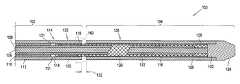
- FIG. 2shows a longitudinal section of an exemplary introducer of the present invention
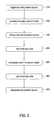
- FIG. 3shows a flowchart depicting an exemplary method of the invention
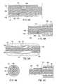
- FIG. 4Ashows a longitudinal section of a portion of an exemplary introducer of the present invention having an extended cell and notch anchoring arrangement and a medial sheath;
- FIG. 4Bshows a longitudinal section of a portion of another exemplary introducer of the present invention having an extended cell and notch anchoring arrangement with no medial sheath;
- FIG. 5Ashows a longitudinal section of a portion of an exemplary introducer of the present invention having a tether attached to the retrograde sheath for anchoring the proximal end of the endoluminal device;
- FIG. 5Bshows a cross section of a portion of another embodiment of an exemplary introducer of the present invention having a channel in the medial sheath for the tether;
- FIG. 5Cshows a longitudinal section of a portion of another exemplary introducer embodiment of the present invention having a tether attached to the inner sheath for anchoring the proximal end of the endoluminal device;
- FIG. 6shows a longitudinal section of another exemplary introducer of the present invention having a holder at the distal end of the endoluminal device
- FIG. 7shows a portion of a longitudinal section of another exemplary introducer of the present invention in which the balloon is contained within the retrograde portion.
- Introducer 100comprises a retrograde portion 102 and an anterograde portion 104 .
- Shaft 106may be solid or tubular, and is surrounded by three concentrically positioned sheaths: inner sheath 108 , medial sheath 110 , and retrograde sheath 112 .
- Medial sheath 110preferably has a fixed position and operates as a radial spacer, separating retrograde sheath distal extension 114 from inner sheath distal extension 116 .
- the distal extension 114 of retrograde sheath 112 and distal extension 116 of inner sheath 108comprise the respective portions of those sheaths located distally of the distal end 111 of medial sheath 110 .
- inner sheath or retrograde sheathmay provide such spacing.
- inner sheathmay have a stepped outside diameter or retrograde sheath may have a stepped inside diameter, such as created by medial sheath being fused to either inner sheath or retrograde sheath, or by any other method that creates an equivalent structure.
- Radial space 118 between retrograde sheath 112 and inner sheath 108may be sufficiently large to allow room for a radial-force-exerting device, such as balloon 120 .
- Inner sheath 108preferably has a fixed position and may include a lumen for communicating pressurized fluid to balloon 120 .
- balloon 120 and proximal end 131 of device 130may be part of anterograde portion 104 and covered by anterograde sheath 126 .
- Anterograde portion 104 of introducer 100includes a distal extension 122 of shaft 106 and distal extension 116 of inner sheath 108 .
- Distal extension 122 of shaft 106terminates with an attachment to radial spacer 125 connected to distal tip 124 .
- Distal tip 124is coupled to anterograde sheath 126 , which extends proximally from distal tip 124 , and is positioned concentrically about shaft distal extension 122 and inner sheath distal extension 116 .
- Radial spacer 125creates an area 128 into which an endoluminal device 130 , such as a stent graft, can be loaded.
- Retrograde sheath 112 and anterograde sheath 126may have a lateral space 132 therebetween, the sheaths may abut one another (not shown) without any space 132 , or the sheaths may laterally overlap one another as depicted by dashed lines 140 in FIG. 2 .
- Dashed lines 140show a proximal extension of anterograde sheath 126 that overlaps retrograde sheath 112 .
- a similar distal extension (not shown) of retrograde sheath 112may laterally overlap anterograde sheath 126 .
- an exemplary method for using introducer 100is depicted in the flowchart shown in FIG. 3 .
- the methodmay be performed, for example, in an operating room or an angiographic suite, preferably under fluoroscopic guidance as is known in the art.
- the introduceris inserted into a body lumen, as indicated in step 210 , distal tip 124 first, from a proximal access site, such as a femoral artery or iliac artery, for vascular deployment.
- a proximal access sitesuch as a femoral artery or iliac artery
- the introduceris threaded into the lumen over a guidewire (not shown) as is well known in the art.
- the access sitemay be surgically exposed and punctured with, for example, an 18-gauge needle as is known in the art.
- proximal end 131 of endoluminal device 130is aligned in an appropriate deployment position. Fluoroscopic guidance and/or a guide wire may be used to guide proximal end 131 into the desired position.
- endoluminal device 130is an AAA stent graft
- proximal end 131 of device 130is positioned in the iliac (not shown), preferably just above a branch of the internal iliac artery (not shown).
- step 230retrograde sheath 112 is retracted at least far enough to expose proximal end 131 of device 130 and balloon 120 .
- the anterograde sheath 126is initially advanced far enough to expose the proximal end and balloon.
- Balloon 120is inflated in step 240 , such as by pressurizing balloon 120 with fluid communicated via a lumen in inner sheath 108 , to exert radial force that compresses the retrograde portion 133 of device 130 against the lumen wall (not shown).
- shaft 106is extended distally to deploy the anterograde portion 135 of device 130 .
- the guidewire and retrograde sheath 112may typically be locked together to prevent movement of the retrograde sheath or the guidewire during extension of the shaft.
- the “retrograde portion” of device 130refers to any portion initially covered by the retrograde sheath (as shown in FIG. 2 ) or any portion underlied by balloon 120 and any portion proximal thereof (as shown in FIG. 7 ), and the “anterograde portion” refers to the remainder of the device distal of the retrograde portion.
- Balloon 120is then deflated in step 260 and introducer 100 is removed from the lumen in accordance with step 270 . If desired, prior to removal from the lumen, balloon 120 may be used for modeling device 130 to better conform to the contours of the lumen wall, as is known in the art.
- introducer 100 and the method depicted in FIG. 3provides means for accurately placing the proximal end of an endoluminal device.
- step 240 of inflating balloon 120may be carried out prior to step 230 of retracting retrograde sheath 112 , so that the balloon exerts radial force compressing retrograde portion 133 of device 130 into the retrograde sheath. Then, after step 250 of extending shaft 106 to deploy anterograde portion 135 of device 130 , balloon 120 is deflated in step 260 and retrograde sheath 106 is retracted in step 230 to complete deployment of the retrograde portion of the device. Finally, the introducer is removed in step 270 .
- the stepsare performed in numerical order as shown in FIG.
- the second methodhas the advantage that the balloon does not press against the lumen wall, but instead presses against the retrograde sheath, thus avoiding exertion of stress on the lumen wall.
- This second methodis particularly desirable in the case of diseased lumen walls, which could be damaged due to the force of the balloon.
- This methodmay sacrifice a few millimeters of accuracy due to recoil of the device 130 . Consequently, the second method may be more desirable for applications in which the small sacrifice in accuracy is medically acceptable.
- a notch 150may be located in medial sheath 110 a .
- a proximally extended portion 131 a of device 130 asuch as an extended cell or a loop, is fixed within notch 150 .
- the retrograde sheath 112is only retracted in step 230 until the proximal end 131 of stent 130 deploys, except for proximally extended portion 131 a .
- a radiopaque deployment marker(not shown) may be used to mark the end 131 so that the retrograde sheath is not retracted too far.
- Steps 240 and 260are omitted from the method steps, as proximally extended portion 131 a remains compressed in notch 150 between medial sheath 110 a and retrograde sheath 112 to hold the proximal end 131 of device 130 in place until the distal portion of the stent has been deployed. Then, prior to removing deployment device in step 270 , retrograde sheath 112 is retracted the remaining distance necessary to release proximally extended portion 131 a from notch 150 .
- a tether 152may be used for anchoring. Distal end 153 of tether 152 is attached to proximal end 131 of device 130 and proximal end 154 of the tether may be attached to the distal end of either retrograde sheath 112 (as shown in FIG. 5A ) or medial sheath 110 (not shown), or to an intermediate portion of inner sheath 108 (shown in FIG. 5C ). Tether 152 may be attached to device 130 and sheath 112 or 110 in any way known in the art, such as by gluing, suturing, stapling, welding, heat shrinking, and the like.
- the tethermay comprise any type of material known in the art, including metal or non-metal filaments.
- the tetheris attached to the device in such a way that it is readily detachable from the device when desired. Suitable mechanisms for detachably connecting a wire to an implantable device are described in U.S. Pat. Nos. 5,354,295 and 5,122,136 to Guglielmi et al., as well as in U.S. patent application Ser. No. 09/852,524, filed on May 10, 2001, by Chris Elliott on behalf of the assignee of this invention, all of which are incorporated herein by reference.
- tether 152may be employed in any way known in the art, including extending proximally all the way back to the access location outside the body lumen.
- medial sheath 110 amay have a lateral channel running its entire length into which tether 152 may extend.
- tether 152may connect to a power supply or a handle for exerting tensional or torsional force, as described in the '524 application.
- the methodis carried out as shown in FIG. 3 up to step 230 , at which point the retrograde sheath 112 is retracted until proximal end 131 of the device 130 deploys, with tether 152 holding proximal end 131 in place.
- the guidewireis then typically locked with retrograde sheath 112 to prevent further movement of the retrograde sheath 112 , and anterograde sheath 126 is advanced by advancing shaft 106 to deploy the anterograde portion of device 130 .
- the remainder of retrograde sheath 112is retracted as part of step 270 to release device 130 from tether 152 .
- proximal end 154 of tether 152is attached to medial sheath 110 instead of retrograde sheath 112 , the medial sheath may be retracted, or if the medial sheath is not retractable, the entire introducer may be retracted to release device 130 from tether 152 in step 270 .
- FIG. 6Another introducer embodiment 600 is shown in FIG. 6 .
- all of the componentsare essentially the same as in embodiment 100 , except that instead of a combination of balloon 120 and retrograde sheath 112 at the proximal end, there is a holder 602 near the distal end of inner sheath extension 116 .
- Anterograde sheath 126(and thus anterograde portion 104 of introducer 600 ) extends to the proximal end 131 of device 130 .
- Holder 602may comprise any material known in the art and may have any geometry known in the art sufficient to hold device 130 in place while anterograde sheath is advanced. A number of geometries and materials useful for holding a stent in place from inside the stent are described in U.S.
- holder 602may be a sleeve of a relatively higher friction material than sheath 126 such that device 130 is frictionally retained while sheath 126 advances.
- holder 602may comprise one or more radial protrusions that exerts an axial restraining force against individual members of device 130 .
- Other structures or combinations of multiple structuresmay also be used as holders.
- a holder 602 at or near the distal end of device 130 as shown in FIG. 6may be beneficial for combination with a balloon at or near the proximal end of the device as shown in FIG. 7 .
- Such a holder 602may minimize potential distal advancement of proximal end 131 of device 130 during the initial advancement of sheath 126 to expose balloon 120 , as may otherwise potentially occur as a result of frictional contact between the anterograde sheath and the device.
- balloon 120may also be provided with a greater frictional engagement force than sheath 126 so that device 130 tends to stay with the balloon rather than move with the sheath. Such a greater frictional engagement force may be the result of a higher coefficient of friction, for example.
- the method of using introducer 600involves steps 210 , 220 , 250 , and 270 , without any of the steps relating to the balloon or the retrograde shaft.
- the embodiment shown in FIG. 6may comprise a minimal set of components comprising shaft 106 , inner sheath 108 , holder 602 mounted directly to the inner sheath 108 , and tip 124 attached to anterograde sheath 126 .
- the remaining components shown in FIG. 6are optional.
- Holder 602is not limited to restraining only the distal end of device 130 .
- holder 602may extend the length of device 130 , an embodiment that may be particularly useful with devices having a relatively low column strength.
- a hybrid of introducers 100 and 600may also be provided comprising both a holder 602 and a balloon 120 or other anchoring means at proximal end 131 of device 130 , with anterograde sheath 126 extending over the proximal end of the device. In such a configuration comprising a balloon, the deployment method follows the method steps in the order shown in FIG.
- the methodcomprises advancing anterograde sheath a sufficient distance to uncover balloon 120 , and then inflating the balloon at step 240 and continuing on with the remainder of the method steps.
- balloon 120once inflated, is capable of anchoring device 130 , holder 602 may be located closer to proximal end 131 of the device so that it engages the device only during the initial advancement of anterograde sheath 126 prior to inflation of the balloon.
- Tethered or extended-portion-and-notch embodimentsmay also be provided with anterograde sheath 126 extending to the proximal end of endoluminal device 130 .
- an extended-portion-and-notch embodiment shown in FIG. 4Bthere may be no medial sheath, such that retrograde sheath 112 a directly contacts inner sheath 108 a , and the notch 150 may be in inner sheath 108 a , retrograde sheath 112 a , or may comprise notch portions 150 a and 150 b in each, respectively, as shown in FIG. 4B .
- the medial sheathmay optionally be present, such as to preserve a constant radial profile throughout the introducer, in which case the notch or a portion of the notch may be located in one or both of the retrograde sheath and the medial sheath.
- the method of using such an embodimentcomprises inserting the device in step 210 , aligning the proximal end in step 220 , extending the shaft to deploy the device 250 , and then retracting the retrograde sheath in step 230 a sufficient distance to release the extended portion from the notch.
- tether 152may just be attached to an intermediate portion of inner sheath 108 as shown in FIG. 5C , or may extend freely (not shown) through the lumen back through the access location and outside the lumen to some means for manipulating the tether, such as the means shown and described in '524 application. As shown in FIG. 5C , tether 152 is wrapped about inner sheath 108 in a manner than fixes it axially and may be further anchored in place with an adhesive.
- Notch 155 in tetherprovides a predetermined weak spot so that the retraction of the introducer is sufficient to break the tether at the notch. It is important that the amount of force required to break tether 152 at a preferred location, such as notch 155 , is less than the amount of force that will break the tether in other locations or remove the affixation of the tether to inner sheath, more than the amount of force necessary to hold proximal end 131 of endoluminal device 130 in place during deployment of its distal end (so that it does not break prematurely), and less than the amount of force that will axially move device 130 once deployed in the lumen (so that breaking the tether does not take the deployed device out of its proper alignment).
- the tethermay also be affixed in a slipknot that requires an amount of force to undo the knot that does not break the tether, pull the deployed device out of alignment, or undo prematurely.
- the dimensions of the introducermay be optimized to prevent damage caused by the anterograde portion being too long.
- One way of shortening the anterograde portion for a particular applicationis to lengthen the retrograde portion.
- anterograde portion and retrograde portionsmay extend over equal lengths of the device, or portion of the device over which the retrograde portion extends may be longer than the portion over which the anterograde portion extends.
- Such embodimentsfor example an introducer wherein the retrograde and anterograde portions extend over equal lengths of the device, may be useful where the location of the proximal end of the device is less important than aligning the middle of the device with a certain region of a lumen.
Landscapes
- Health & Medical Sciences (AREA)
- Engineering & Computer Science (AREA)
- Biomedical Technology (AREA)
- General Health & Medical Sciences (AREA)
- Veterinary Medicine (AREA)
- Transplantation (AREA)
- Heart & Thoracic Surgery (AREA)
- Vascular Medicine (AREA)
- Life Sciences & Earth Sciences (AREA)
- Animal Behavior & Ethology (AREA)
- Cardiology (AREA)
- Public Health (AREA)
- Oral & Maxillofacial Surgery (AREA)
- Prostheses (AREA)
- Vehicle Body Suspensions (AREA)
- Steering Control In Accordance With Driving Conditions (AREA)
- Paper (AREA)
- Surgical Instruments (AREA)
- Mechanical Treatment Of Semiconductor (AREA)
- Media Introduction/Drainage Providing Device (AREA)
Abstract
Description
Claims (15)
Priority Applications (11)
| Application Number | Priority Date | Filing Date | Title |
|---|---|---|---|
| US10/081,641US7887573B2 (en) | 2002-02-22 | 2002-02-22 | Method and apparatus for deployment of an endoluminal device |
| CA2476734ACA2476734C (en) | 2002-02-22 | 2003-02-19 | Method and apparatus for deployment of an endoluminal device |
| DE60312662TDE60312662T2 (en) | 2002-02-22 | 2003-02-19 | SYSTEM FOR INSERTING AN ENDOLUMINAL DEVICE |
| AU2003215288AAU2003215288A1 (en) | 2002-02-22 | 2003-02-19 | Method and apparatus for deployment of an endoluminal device |
| ES03711107TES2283757T3 (en) | 2002-02-22 | 2003-02-19 | DEVICE FOR THE DEPLOYMENT OF AN ENDOLUMINAL DEVICE. |
| PCT/US2003/004832WO2003071988A1 (en) | 2002-02-22 | 2003-02-19 | Method and apparatus for deployment of an endoluminal device |
| JP2003570736AJP4364647B2 (en) | 2002-02-22 | 2003-02-19 | Introducer |
| EP03711107AEP1482866B1 (en) | 2002-02-22 | 2003-02-19 | Apparatus for deployment of an endoluminal device |
| AT03711107TATE357196T1 (en) | 2002-02-22 | 2003-02-19 | SYSTEM FOR DEPLOYING AN ENDOLUMINAL DEVICE |
| US11/363,015US7892272B2 (en) | 2002-02-22 | 2006-02-27 | Method and apparatus for deployment of an endoluminal device |
| US12/987,083US20110106235A1 (en) | 2002-02-22 | 2011-01-08 | Method and apparatus for deployment of an endoluminal device |
Applications Claiming Priority (1)
| Application Number | Priority Date | Filing Date | Title |
|---|---|---|---|
| US10/081,641US7887573B2 (en) | 2002-02-22 | 2002-02-22 | Method and apparatus for deployment of an endoluminal device |
Related Child Applications (1)
| Application Number | Title | Priority Date | Filing Date |
|---|---|---|---|
| US11/363,015DivisionUS7892272B2 (en) | 2002-02-22 | 2006-02-27 | Method and apparatus for deployment of an endoluminal device |
Publications (2)
| Publication Number | Publication Date |
|---|---|
| US20030163155A1 US20030163155A1 (en) | 2003-08-28 |
| US7887573B2true US7887573B2 (en) | 2011-02-15 |
Family
ID=27752977
Family Applications (3)
| Application Number | Title | Priority Date | Filing Date |
|---|---|---|---|
| US10/081,641Expired - Fee RelatedUS7887573B2 (en) | 2002-02-22 | 2002-02-22 | Method and apparatus for deployment of an endoluminal device |
| US11/363,015Expired - Fee RelatedUS7892272B2 (en) | 2002-02-22 | 2006-02-27 | Method and apparatus for deployment of an endoluminal device |
| US12/987,083AbandonedUS20110106235A1 (en) | 2002-02-22 | 2011-01-08 | Method and apparatus for deployment of an endoluminal device |
Family Applications After (2)
| Application Number | Title | Priority Date | Filing Date |
|---|---|---|---|
| US11/363,015Expired - Fee RelatedUS7892272B2 (en) | 2002-02-22 | 2006-02-27 | Method and apparatus for deployment of an endoluminal device |
| US12/987,083AbandonedUS20110106235A1 (en) | 2002-02-22 | 2011-01-08 | Method and apparatus for deployment of an endoluminal device |
Country Status (9)
| Country | Link |
|---|---|
| US (3) | US7887573B2 (en) |
| EP (1) | EP1482866B1 (en) |
| JP (1) | JP4364647B2 (en) |
| AT (1) | ATE357196T1 (en) |
| AU (1) | AU2003215288A1 (en) |
| CA (1) | CA2476734C (en) |
| DE (1) | DE60312662T2 (en) |
| ES (1) | ES2283757T3 (en) |
| WO (1) | WO2003071988A1 (en) |
Cited By (6)
| Publication number | Priority date | Publication date | Assignee | Title |
|---|---|---|---|---|
| US20080140189A1 (en)* | 2006-12-06 | 2008-06-12 | Corevalve, Inc. | System and method for transapical delivery of an annulus anchored self-expanding valve |
| US20140142688A1 (en)* | 2012-11-20 | 2014-05-22 | Medtronic CV Luxembourg S.a.r.l. | Medical Device Delivery System and Methods of Delivering a Medical Device |
| US8986363B2 (en) | 2009-12-30 | 2015-03-24 | Cook Medical Technologies Llc | Proximal release delivery system |
| US20160128857A1 (en)* | 2010-06-08 | 2016-05-12 | Veniti, Inc. | Bi-directional stent delivery system |
| US10687969B2 (en) | 2016-06-29 | 2020-06-23 | Boston Scientific Scimed, Inc. | Stent delivery system |
| US10857016B2 (en) | 2017-04-26 | 2020-12-08 | Boston Scientific Scimed, Inc. | Proximal and distal release delivery system |
Families Citing this family (95)
| Publication number | Priority date | Publication date | Assignee | Title |
|---|---|---|---|---|
| EP0850607A1 (en) | 1996-12-31 | 1998-07-01 | Cordis Corporation | Valve prosthesis for implantation in body channels |
| US6454799B1 (en) | 2000-04-06 | 2002-09-24 | Edwards Lifesciences Corporation | Minimally-invasive heart valves and methods of use |
| US6733525B2 (en) | 2001-03-23 | 2004-05-11 | Edwards Lifesciences Corporation | Rolled minimally-invasive heart valves and methods of use |
| US6893460B2 (en) | 2001-10-11 | 2005-05-17 | Percutaneous Valve Technologies Inc. | Implantable prosthetic valve |
| US7137993B2 (en) | 2001-12-03 | 2006-11-21 | Xtent, Inc. | Apparatus and methods for delivery of multiple distributed stents |
| US7892273B2 (en) | 2001-12-03 | 2011-02-22 | Xtent, Inc. | Custom length stent apparatus |
| US7004964B2 (en)* | 2002-02-22 | 2006-02-28 | Scimed Life Systems, Inc. | Apparatus and method for deployment of an endoluminal device |
| US7887573B2 (en) | 2002-02-22 | 2011-02-15 | Boston Scientific Scimed, Inc. | Method and apparatus for deployment of an endoluminal device |
| US6866679B2 (en) | 2002-03-12 | 2005-03-15 | Ev3 Inc. | Everting stent and stent delivery system |
| US7553324B2 (en)* | 2003-10-14 | 2009-06-30 | Xtent, Inc. | Fixed stent delivery devices and methods |
| US7326236B2 (en) | 2003-12-23 | 2008-02-05 | Xtent, Inc. | Devices and methods for controlling and indicating the length of an interventional element |
| US7323006B2 (en) | 2004-03-30 | 2008-01-29 | Xtent, Inc. | Rapid exchange interventional devices and methods |
| US20050246008A1 (en)* | 2004-04-30 | 2005-11-03 | Novostent Corporation | Delivery system for vascular prostheses and methods of use |
| US20060206200A1 (en) | 2004-05-25 | 2006-09-14 | Chestnut Medical Technologies, Inc. | Flexible vascular occluding device |
| US8623067B2 (en) | 2004-05-25 | 2014-01-07 | Covidien Lp | Methods and apparatus for luminal stenting |
| US8617234B2 (en) | 2004-05-25 | 2013-12-31 | Covidien Lp | Flexible vascular occluding device |
| CA2565106C (en) | 2004-05-25 | 2013-11-05 | Chestnut Medical Technologies, Inc. | Flexible vascular occluding device |
| US8267985B2 (en) | 2005-05-25 | 2012-09-18 | Tyco Healthcare Group Lp | System and method for delivering and deploying an occluding device within a vessel |
| CA2758946C (en) | 2004-05-25 | 2014-10-21 | Tyco Healthcare Group Lp | Vascular stenting for aneurysms |
| US8317859B2 (en) | 2004-06-28 | 2012-11-27 | J.W. Medical Systems Ltd. | Devices and methods for controlling expandable prostheses during deployment |
| US20050288766A1 (en) | 2004-06-28 | 2005-12-29 | Xtent, Inc. | Devices and methods for controlling expandable prostheses during deployment |
| AU2005332044B2 (en) | 2005-05-25 | 2012-01-19 | Covidien Lp | System and method for delivering and deploying and occluding device within a vessel |
| US8273101B2 (en) | 2005-05-25 | 2012-09-25 | Tyco Healthcare Group Lp | System and method for delivering and deploying an occluding device within a vessel |
| US7670365B2 (en)* | 2005-09-23 | 2010-03-02 | BostonScientific Scimed, Inc. | Secured stent delivery system |
| US8152833B2 (en) | 2006-02-22 | 2012-04-10 | Tyco Healthcare Group Lp | Embolic protection systems having radiopaque filter mesh |
| WO2007109621A2 (en) | 2006-03-20 | 2007-09-27 | Xtent, Inc. | Apparatus and methods for deployment of linked prosthetic segments |
| US20080114437A1 (en)* | 2006-11-13 | 2008-05-15 | Boston Scientific Scimed, Inc. | Self-expanding side branch bifurcated stent |
| US8236045B2 (en) | 2006-12-22 | 2012-08-07 | Edwards Lifesciences Corporation | Implantable prosthetic valve assembly and method of making the same |
| US20080199510A1 (en) | 2007-02-20 | 2008-08-21 | Xtent, Inc. | Thermo-mechanically controlled implants and methods of use |
| US8486132B2 (en)* | 2007-03-22 | 2013-07-16 | J.W. Medical Systems Ltd. | Devices and methods for controlling expandable prostheses during deployment |
| KR100822045B1 (en)* | 2007-04-23 | 2008-04-15 | (주) 태웅메디칼 | Stent insertion device for body stenosis |
| WO2009062264A1 (en)* | 2007-11-15 | 2009-05-22 | Endogad Research Pty Limited | Hybrid intraluminal device |
| WO2009091509A1 (en) | 2008-01-16 | 2009-07-23 | St. Jude Medical, Inc. | Delivery and retrieval systems for collapsible/expandable prosthetic heart valves |
| EP3912597A1 (en) | 2008-02-29 | 2021-11-24 | Edwards Lifesciences Corporation | Expandable member for deploying a prosthetic device |
| US9101503B2 (en) | 2008-03-06 | 2015-08-11 | J.W. Medical Systems Ltd. | Apparatus having variable strut length and methods of use |
| US20090276040A1 (en) | 2008-05-01 | 2009-11-05 | Edwards Lifesciences Corporation | Device and method for replacing mitral valve |
| WO2009140437A1 (en) | 2008-05-13 | 2009-11-19 | Nfocus Neuromedical, Inc. | Braid implant delivery systems |
| US8323335B2 (en) | 2008-06-20 | 2012-12-04 | Edwards Lifesciences Corporation | Retaining mechanisms for prosthetic valves and methods for using |
| US8652202B2 (en) | 2008-08-22 | 2014-02-18 | Edwards Lifesciences Corporation | Prosthetic heart valve and delivery apparatus |
| US8690936B2 (en) | 2008-10-10 | 2014-04-08 | Edwards Lifesciences Corporation | Expandable sheath for introducing an endovascular delivery device into a body |
| US8986361B2 (en)* | 2008-10-17 | 2015-03-24 | Medtronic Corevalve, Inc. | Delivery system for deployment of medical devices |
| GB0901496D0 (en)* | 2009-01-29 | 2009-03-11 | Angiomed Ag | Delivery device for delivering a stent device |
| CA2961053C (en) | 2009-04-15 | 2019-04-30 | Edwards Lifesciences Cardiaq Llc | Vascular implant and delivery system |
| NZ596179A (en) | 2009-04-29 | 2014-05-30 | Cleveland Clinic Foundation | Apparatus and method for replacing a diseased cardiac valve |
| US20110218608A1 (en)* | 2009-09-10 | 2011-09-08 | Novostent Corporation | Vascular Prosthesis Delivery System and Method |
| US8652203B2 (en) | 2010-09-23 | 2014-02-18 | Cardiaq Valve Technologies, Inc. | Replacement heart valves, delivery devices and methods |
| US8449599B2 (en) | 2009-12-04 | 2013-05-28 | Edwards Lifesciences Corporation | Prosthetic valve for replacing mitral valve |
| US9155619B2 (en) | 2011-02-25 | 2015-10-13 | Edwards Lifesciences Corporation | Prosthetic heart valve delivery apparatus |
| US20120266892A1 (en)* | 2011-04-21 | 2012-10-25 | Hologic, Inc. | Tethered implant and related method of use |
| US9289282B2 (en) | 2011-05-31 | 2016-03-22 | Edwards Lifesciences Corporation | System and method for treating valve insufficiency or vessel dilatation |
| US20130226278A1 (en) | 2012-02-23 | 2013-08-29 | Tyco Healthcare Group Lp | Methods and apparatus for luminal stenting |
| US9072624B2 (en) | 2012-02-23 | 2015-07-07 | Covidien Lp | Luminal stenting |
| US9078659B2 (en) | 2012-04-23 | 2015-07-14 | Covidien Lp | Delivery system with hooks for resheathability |
| US9155647B2 (en) | 2012-07-18 | 2015-10-13 | Covidien Lp | Methods and apparatus for luminal stenting |
| US9724222B2 (en) | 2012-07-20 | 2017-08-08 | Covidien Lp | Resheathable stent delivery system |
| US9510946B2 (en) | 2012-09-06 | 2016-12-06 | Edwards Lifesciences Corporation | Heart valve sealing devices |
| US9301831B2 (en) | 2012-10-30 | 2016-04-05 | Covidien Lp | Methods for attaining a predetermined porosity of a vascular device |
| US9452070B2 (en) | 2012-10-31 | 2016-09-27 | Covidien Lp | Methods and systems for increasing a density of a region of a vascular device |
| US9943427B2 (en) | 2012-11-06 | 2018-04-17 | Covidien Lp | Shaped occluding devices and methods of using the same |
| US9439763B2 (en) | 2013-02-04 | 2016-09-13 | Edwards Lifesciences Corporation | Prosthetic valve for replacing mitral valve |
| US9157174B2 (en) | 2013-02-05 | 2015-10-13 | Covidien Lp | Vascular device for aneurysm treatment and providing blood flow into a perforator vessel |
| US9168129B2 (en) | 2013-02-12 | 2015-10-27 | Edwards Lifesciences Corporation | Artificial heart valve with scalloped frame design |
| US20140277427A1 (en) | 2013-03-14 | 2014-09-18 | Cardiaq Valve Technologies, Inc. | Prosthesis for atraumatically grasping intralumenal tissue and methods of delivery |
| EP2999436B1 (en) | 2013-05-20 | 2018-08-29 | Edwards Lifesciences Corporation | Prosthetic heart valve delivery apparatus |
| US10130500B2 (en) | 2013-07-25 | 2018-11-20 | Covidien Lp | Methods and apparatus for luminal stenting |
| US10045867B2 (en) | 2013-08-27 | 2018-08-14 | Covidien Lp | Delivery of medical devices |
| US9782186B2 (en) | 2013-08-27 | 2017-10-10 | Covidien Lp | Vascular intervention system |
| US9622863B2 (en) | 2013-11-22 | 2017-04-18 | Edwards Lifesciences Corporation | Aortic insufficiency repair device and method |
| US10098734B2 (en) | 2013-12-05 | 2018-10-16 | Edwards Lifesciences Corporation | Prosthetic heart valve and delivery apparatus |
| MX2016016493A (en)* | 2014-05-05 | 2017-12-20 | Endosphere Inc | System and method for ups battery monitoring and data analysis. |
| US9532870B2 (en) | 2014-06-06 | 2017-01-03 | Edwards Lifesciences Corporation | Prosthetic valve for replacing a mitral valve |
| US10195026B2 (en) | 2014-07-22 | 2019-02-05 | Edwards Lifesciences Corporation | Mitral valve anchoring |
| US10058424B2 (en) | 2014-08-21 | 2018-08-28 | Edwards Lifesciences Corporation | Dual-flange prosthetic valve frame |
| KR20170066470A (en) | 2014-09-28 | 2017-06-14 | 카디오키네틱스 인크. | Apparatuses for treating cardiac dysfunction |
| US10531951B2 (en) | 2014-11-26 | 2020-01-14 | Edwards Lifesciences Corporation | Transcatheter prosthetic heart valve and delivery system |
| KR101696811B1 (en)* | 2015-02-10 | 2017-01-17 | 주식회사 엠아이텍 | Catheter |
| WO2016153918A1 (en) | 2015-03-20 | 2016-09-29 | Cardiokinetix, Inc. | Systems and methods for delivering an implantable device |
| US10010417B2 (en) | 2015-04-16 | 2018-07-03 | Edwards Lifesciences Corporation | Low-profile prosthetic heart valve for replacing a mitral valve |
| US10064718B2 (en) | 2015-04-16 | 2018-09-04 | Edwards Lifesciences Corporation | Low-profile prosthetic heart valve for replacing a mitral valve |
| US10470876B2 (en) | 2015-11-10 | 2019-11-12 | Edwards Lifesciences Corporation | Transcatheter heart valve for replacing natural mitral valve |
| US10376364B2 (en) | 2015-11-10 | 2019-08-13 | Edwards Lifesciences Corporation | Implant delivery capsule |
| US20170290691A1 (en)* | 2016-04-12 | 2017-10-12 | Idev Technologies, Inc. | Stent deployment system including multiple stent-engaging elements |
| US10758348B2 (en) | 2016-11-02 | 2020-09-01 | Edwards Lifesciences Corporation | Supra and sub-annular mitral valve delivery system |
| US10376396B2 (en) | 2017-01-19 | 2019-08-13 | Covidien Lp | Coupling units for medical device delivery systems |
| US10959846B2 (en) | 2017-05-10 | 2021-03-30 | Edwards Lifesciences Corporation | Mitral valve spacer device |
| US11123209B2 (en) | 2018-04-12 | 2021-09-21 | Covidien Lp | Medical device delivery |
| US11413176B2 (en) | 2018-04-12 | 2022-08-16 | Covidien Lp | Medical device delivery |
| US10786377B2 (en) | 2018-04-12 | 2020-09-29 | Covidien Lp | Medical device delivery |
| US11071637B2 (en) | 2018-04-12 | 2021-07-27 | Covidien Lp | Medical device delivery |
| ES2982566T3 (en) | 2019-04-23 | 2024-10-16 | Edwards Lifesciences Corp | Motorized implant delivery system |
| US11413174B2 (en) | 2019-06-26 | 2022-08-16 | Covidien Lp | Core assembly for medical device delivery systems |
| EP4247297A1 (en) | 2020-12-18 | 2023-09-27 | Edwards Lifesciences Corporation | Storage jar assembly for aprosthetic heart valve |
| US12042413B2 (en) | 2021-04-07 | 2024-07-23 | Covidien Lp | Delivery of medical devices |
| US12109137B2 (en) | 2021-07-30 | 2024-10-08 | Covidien Lp | Medical device delivery |
| US11944558B2 (en) | 2021-08-05 | 2024-04-02 | Covidien Lp | Medical device delivery devices, systems, and methods |
Citations (50)
| Publication number | Priority date | Publication date | Assignee | Title |
|---|---|---|---|---|
| US4140126A (en) | 1977-02-18 | 1979-02-20 | Choudhury M Hasan | Method for performing aneurysm repair |
| US4732152A (en) | 1984-12-05 | 1988-03-22 | Medinvent S.A. | Device for implantation and a method of implantation in a vessel using such device |
| US4787899A (en) | 1983-12-09 | 1988-11-29 | Lazarus Harrison M | Intraluminal graft device, system and method |
| US4950227A (en) | 1988-11-07 | 1990-08-21 | Boston Scientific Corporation | Stent delivery system |
| US5078720A (en)* | 1990-05-02 | 1992-01-07 | American Medical Systems, Inc. | Stent placement instrument and method |
| US5122136A (en) | 1990-03-13 | 1992-06-16 | The Regents Of The University Of California | Endovascular electrolytically detachable guidewire tip for the electroformation of thrombus in arteries, veins, aneurysms, vascular malformations and arteriovenous fistulas |
| US5148548A (en) | 1989-12-19 | 1992-09-15 | Northern Telecom Limited | Method of monitoring cellular radio channels to avoid adjacent and co-channel interference |
| US5158548A (en) | 1990-04-25 | 1992-10-27 | Advanced Cardiovascular Systems, Inc. | Method and system for stent delivery |
| US5201757A (en)* | 1992-04-03 | 1993-04-13 | Schneider (Usa) Inc. | Medial region deployment of radially self-expanding stents |
| US5354295A (en) | 1990-03-13 | 1994-10-11 | Target Therapeutics, Inc. | In an endovascular electrolytically detachable wire and tip for the formation of thrombus in arteries, veins, aneurysms, vascular malformations and arteriovenous fistulas |
| EP0637454A1 (en) | 1993-08-05 | 1995-02-08 | Endovascular Technologies, Inc. | Multicapsule intralaminal grafting system and method |
| US5409495A (en)* | 1993-08-24 | 1995-04-25 | Advanced Cardiovascular Systems, Inc. | Apparatus for uniformly implanting a stent |
| US5415664A (en) | 1994-03-30 | 1995-05-16 | Corvita Corporation | Method and apparatus for introducing a stent or a stent-graft |
| US5445646A (en)* | 1993-10-22 | 1995-08-29 | Scimed Lifesystems, Inc. | Single layer hydraulic sheath stent delivery apparatus and method |
| US5456694A (en) | 1994-05-13 | 1995-10-10 | Stentco, Inc. | Device for delivering and deploying intraluminal devices |
| EP0684022A2 (en) | 1994-05-12 | 1995-11-29 | Endovascular Technologies, Inc. | Bifurcated multicapsule intraluminal grafting system |
| US5480423A (en) | 1993-05-20 | 1996-01-02 | Boston Scientific Corporation | Prosthesis delivery |
| WO1996024308A1 (en) | 1995-02-07 | 1996-08-15 | Cook Incorporated | Expandable transluminal graft prosthesis for repair of aneurysm and method for implanting |
| US5591228A (en) | 1995-05-09 | 1997-01-07 | Edoga; John K. | Methods for treating abdominal aortic aneurysms |
| US5609627A (en) | 1994-02-09 | 1997-03-11 | Boston Scientific Technology, Inc. | Method for delivering a bifurcated endoluminal prosthesis |
| US5634928A (en) | 1994-12-07 | 1997-06-03 | Fischell Robert | Integrated dual-function catheter system and method for balloon angioplasty and stent delivery |
| US5662675A (en) | 1995-02-24 | 1997-09-02 | Intervascular, Inc. | Delivery catheter assembly |
| US5683451A (en) | 1994-06-08 | 1997-11-04 | Cardiovascular Concepts, Inc. | Apparatus and methods for deployment release of intraluminal prostheses |
| US5695499A (en)* | 1994-10-27 | 1997-12-09 | Schneider (Usa) Inc. | Medical device supported by spirally wound wire |
| WO1998009583A2 (en) | 1996-09-06 | 1998-03-12 | William Cook Europe A/S | An aggregate for transluminal insertion of a tubular stent, and an endovascular graft device |
| US5800526A (en) | 1995-03-17 | 1998-09-01 | Endotex Interventional Systems, Inc. | Multi-anchor stent |
| US5807101A (en) | 1996-01-17 | 1998-09-15 | Scalzo; Josephine | Universal occlusal matrix |
| US5817101A (en)* | 1997-03-13 | 1998-10-06 | Schneider (Usa) Inc | Fluid actuated stent delivery system |
| US5843164A (en) | 1994-11-15 | 1998-12-01 | Advanced Carrdiovascular Systems, Inc. | Intraluminal stent for attaching a graft |
| WO1998053761A1 (en) | 1997-05-26 | 1998-12-03 | William A. Cook Australia Pty. Ltd. | A prosthesis and a method and means of deploying a prosthesis |
| US5860998A (en) | 1996-11-25 | 1999-01-19 | C. R. Bard, Inc. | Deployment device for tubular expandable prosthesis |
| WO1999047075A1 (en) | 1998-03-17 | 1999-09-23 | Medicorp S.A. | Reversible-action endoprosthesis delivery device |
| WO1999049812A2 (en) | 1998-03-31 | 1999-10-07 | Scimed Life Systems, Incorporated | Mesh stent and delivery system |
| US5989280A (en)* | 1993-10-22 | 1999-11-23 | Scimed Lifesystems, Inc | Stent delivery apparatus and method |
| US6022336A (en)* | 1996-05-20 | 2000-02-08 | Percusurge, Inc. | Catheter system for emboli containment |
| US6068634A (en)* | 1996-08-23 | 2000-05-30 | Scimed Life Systems, Inc. | Stent delivery system |
| US6102942A (en) | 1998-03-30 | 2000-08-15 | Endovascular Technologies, Inc. | Stent/graft deployment catheter with a stent/graft attachment mechanism |
| US6168610B1 (en) | 1994-02-10 | 2001-01-02 | Endovascular Systems, Inc. | Method for endoluminally excluding an aortic aneurysm |
| US6183443B1 (en) | 1992-10-15 | 2001-02-06 | Scimed Life Systems, Inc. | Expandable introducer sheath |
| WO2001010345A1 (en) | 1999-08-05 | 2001-02-15 | Aesculap Ag & Co. Kg | Insertion catheter for vascular prostheses |
| US6290710B1 (en)* | 1999-12-29 | 2001-09-18 | Advanced Cardiovascular Systems, Inc. | Embolic protection device |
| US20010044648A1 (en) | 1998-02-05 | 2001-11-22 | Medtronic, Inc. | Radially-expandable stent and delivery system |
| US6322586B1 (en) | 2000-01-10 | 2001-11-27 | Scimed Life Systems, Inc. | Catheter tip designs and method of manufacture |
| US6468244B1 (en) | 1997-12-19 | 2002-10-22 | James E. Leone | Catheter system having fullerenes and method |
| US20030050684A1 (en)* | 2001-09-10 | 2003-03-13 | Abrams Robert M. | Internal restraint for delivery of self-expanding stents |
| US6544223B1 (en) | 2001-01-05 | 2003-04-08 | Advanced Cardiovascular Systems, Inc. | Balloon catheter for delivering therapeutic agents |
| US6607551B1 (en)* | 1999-05-20 | 2003-08-19 | Scimed Life Systems, Inc. | Stent delivery system with nested stabilizer |
| US20030163155A1 (en) | 2002-02-22 | 2003-08-28 | Haverkost Patrick A. | Method and apparatus for deployment of an endoluminal device |
| US6613075B1 (en) | 1999-10-27 | 2003-09-02 | Cordis Corporation | Rapid exchange self-expanding stent delivery catheter system |
| US20040133263A1 (en) | 1996-08-23 | 2004-07-08 | Scimed Life Systems, Inc. | Stent delivery system having stent securement apparatus |
Family Cites Families (9)
| Publication number | Priority date | Publication date | Assignee | Title |
|---|---|---|---|---|
| WO1995029646A1 (en)* | 1994-04-29 | 1995-11-09 | Boston Scientific Corporation | Medical prosthetic stent and method of manufacture |
| US5824041A (en)* | 1994-06-08 | 1998-10-20 | Medtronic, Inc. | Apparatus and methods for placement and repositioning of intraluminal prostheses |
| US5873907A (en)* | 1998-01-27 | 1999-02-23 | Endotex Interventional Systems, Inc. | Electrolytic stent delivery system and methods of use |
| US6585758B1 (en)* | 1999-11-16 | 2003-07-01 | Scimed Life Systems, Inc. | Multi-section filamentary endoluminal stent |
| US6610087B1 (en)* | 1999-11-16 | 2003-08-26 | Scimed Life Systems, Inc. | Endoluminal stent having a matched stiffness region and/or a stiffness gradient and methods for providing stent kink resistance |
| US6582460B1 (en)* | 2000-11-20 | 2003-06-24 | Advanced Cardiovascular Systems, Inc. | System and method for accurately deploying a stent |
| US6716238B2 (en)* | 2001-05-10 | 2004-04-06 | Scimed Life Systems, Inc. | Stent with detachable tethers and method of using same |
| US7235095B2 (en)* | 2002-02-22 | 2007-06-26 | Scimed Life Systems, Inc. | Method and system for deploying multi-part endoluminal devices |
| US7004964B2 (en)* | 2002-02-22 | 2006-02-28 | Scimed Life Systems, Inc. | Apparatus and method for deployment of an endoluminal device |
- 2002
- 2002-02-22USUS10/081,641patent/US7887573B2/ennot_activeExpired - Fee Related
- 2003
- 2003-02-19EPEP03711107Apatent/EP1482866B1/ennot_activeExpired - Lifetime
- 2003-02-19DEDE60312662Tpatent/DE60312662T2/ennot_activeExpired - Lifetime
- 2003-02-19WOPCT/US2003/004832patent/WO2003071988A1/enactiveIP Right Grant
- 2003-02-19ATAT03711107Tpatent/ATE357196T1/ennot_activeIP Right Cessation
- 2003-02-19CACA2476734Apatent/CA2476734C/ennot_activeExpired - Fee Related
- 2003-02-19ESES03711107Tpatent/ES2283757T3/ennot_activeExpired - Lifetime
- 2003-02-19AUAU2003215288Apatent/AU2003215288A1/ennot_activeAbandoned
- 2003-02-19JPJP2003570736Apatent/JP4364647B2/ennot_activeExpired - Fee Related
- 2006
- 2006-02-27USUS11/363,015patent/US7892272B2/ennot_activeExpired - Fee Related
- 2011
- 2011-01-08USUS12/987,083patent/US20110106235A1/ennot_activeAbandoned
Patent Citations (52)
| Publication number | Priority date | Publication date | Assignee | Title |
|---|---|---|---|---|
| US4140126A (en) | 1977-02-18 | 1979-02-20 | Choudhury M Hasan | Method for performing aneurysm repair |
| US4787899A (en) | 1983-12-09 | 1988-11-29 | Lazarus Harrison M | Intraluminal graft device, system and method |
| US4732152A (en) | 1984-12-05 | 1988-03-22 | Medinvent S.A. | Device for implantation and a method of implantation in a vessel using such device |
| US4950227A (en) | 1988-11-07 | 1990-08-21 | Boston Scientific Corporation | Stent delivery system |
| US5148548A (en) | 1989-12-19 | 1992-09-15 | Northern Telecom Limited | Method of monitoring cellular radio channels to avoid adjacent and co-channel interference |
| US5354295A (en) | 1990-03-13 | 1994-10-11 | Target Therapeutics, Inc. | In an endovascular electrolytically detachable wire and tip for the formation of thrombus in arteries, veins, aneurysms, vascular malformations and arteriovenous fistulas |
| US5122136A (en) | 1990-03-13 | 1992-06-16 | The Regents Of The University Of California | Endovascular electrolytically detachable guidewire tip for the electroformation of thrombus in arteries, veins, aneurysms, vascular malformations and arteriovenous fistulas |
| US5158548A (en) | 1990-04-25 | 1992-10-27 | Advanced Cardiovascular Systems, Inc. | Method and system for stent delivery |
| US5078720A (en)* | 1990-05-02 | 1992-01-07 | American Medical Systems, Inc. | Stent placement instrument and method |
| US5201757A (en)* | 1992-04-03 | 1993-04-13 | Schneider (Usa) Inc. | Medial region deployment of radially self-expanding stents |
| US6183443B1 (en) | 1992-10-15 | 2001-02-06 | Scimed Life Systems, Inc. | Expandable introducer sheath |
| US5480423A (en) | 1993-05-20 | 1996-01-02 | Boston Scientific Corporation | Prosthesis delivery |
| EP0637454A1 (en) | 1993-08-05 | 1995-02-08 | Endovascular Technologies, Inc. | Multicapsule intralaminal grafting system and method |
| US5409495A (en)* | 1993-08-24 | 1995-04-25 | Advanced Cardiovascular Systems, Inc. | Apparatus for uniformly implanting a stent |
| US5445646A (en)* | 1993-10-22 | 1995-08-29 | Scimed Lifesystems, Inc. | Single layer hydraulic sheath stent delivery apparatus and method |
| US5989280A (en)* | 1993-10-22 | 1999-11-23 | Scimed Lifesystems, Inc | Stent delivery apparatus and method |
| US5609627A (en) | 1994-02-09 | 1997-03-11 | Boston Scientific Technology, Inc. | Method for delivering a bifurcated endoluminal prosthesis |
| US6168610B1 (en) | 1994-02-10 | 2001-01-02 | Endovascular Systems, Inc. | Method for endoluminally excluding an aortic aneurysm |
| US5415664A (en) | 1994-03-30 | 1995-05-16 | Corvita Corporation | Method and apparatus for introducing a stent or a stent-graft |
| EP0684022A2 (en) | 1994-05-12 | 1995-11-29 | Endovascular Technologies, Inc. | Bifurcated multicapsule intraluminal grafting system |
| US5456694A (en) | 1994-05-13 | 1995-10-10 | Stentco, Inc. | Device for delivering and deploying intraluminal devices |
| US5683451A (en) | 1994-06-08 | 1997-11-04 | Cardiovascular Concepts, Inc. | Apparatus and methods for deployment release of intraluminal prostheses |
| US5695499A (en)* | 1994-10-27 | 1997-12-09 | Schneider (Usa) Inc. | Medical device supported by spirally wound wire |
| US5843164A (en) | 1994-11-15 | 1998-12-01 | Advanced Carrdiovascular Systems, Inc. | Intraluminal stent for attaching a graft |
| US5634928A (en) | 1994-12-07 | 1997-06-03 | Fischell Robert | Integrated dual-function catheter system and method for balloon angioplasty and stent delivery |
| WO1996024308A1 (en) | 1995-02-07 | 1996-08-15 | Cook Incorporated | Expandable transluminal graft prosthesis for repair of aneurysm and method for implanting |
| US5662675A (en) | 1995-02-24 | 1997-09-02 | Intervascular, Inc. | Delivery catheter assembly |
| US5800526A (en) | 1995-03-17 | 1998-09-01 | Endotex Interventional Systems, Inc. | Multi-anchor stent |
| US5591228A (en) | 1995-05-09 | 1997-01-07 | Edoga; John K. | Methods for treating abdominal aortic aneurysms |
| US5807101A (en) | 1996-01-17 | 1998-09-15 | Scalzo; Josephine | Universal occlusal matrix |
| US6022336A (en)* | 1996-05-20 | 2000-02-08 | Percusurge, Inc. | Catheter system for emboli containment |
| US6068634A (en)* | 1996-08-23 | 2000-05-30 | Scimed Life Systems, Inc. | Stent delivery system |
| US20040133263A1 (en) | 1996-08-23 | 2004-07-08 | Scimed Life Systems, Inc. | Stent delivery system having stent securement apparatus |
| WO1998009583A2 (en) | 1996-09-06 | 1998-03-12 | William Cook Europe A/S | An aggregate for transluminal insertion of a tubular stent, and an endovascular graft device |
| US5860998A (en) | 1996-11-25 | 1999-01-19 | C. R. Bard, Inc. | Deployment device for tubular expandable prosthesis |
| US6056759A (en)* | 1997-03-13 | 2000-05-02 | Schneider (Usa) Inc. | Fluid actuated stent delivery system |
| US5817101A (en)* | 1997-03-13 | 1998-10-06 | Schneider (Usa) Inc | Fluid actuated stent delivery system |
| WO1998053761A1 (en) | 1997-05-26 | 1998-12-03 | William A. Cook Australia Pty. Ltd. | A prosthesis and a method and means of deploying a prosthesis |
| US6468244B1 (en) | 1997-12-19 | 2002-10-22 | James E. Leone | Catheter system having fullerenes and method |
| US20010044648A1 (en) | 1998-02-05 | 2001-11-22 | Medtronic, Inc. | Radially-expandable stent and delivery system |
| US6042589A (en)* | 1998-03-17 | 2000-03-28 | Medicorp, S.A. | Reversible-action endoprosthesis delivery device |
| WO1999047075A1 (en) | 1998-03-17 | 1999-09-23 | Medicorp S.A. | Reversible-action endoprosthesis delivery device |
| US6102942A (en) | 1998-03-30 | 2000-08-15 | Endovascular Technologies, Inc. | Stent/graft deployment catheter with a stent/graft attachment mechanism |
| WO1999049812A2 (en) | 1998-03-31 | 1999-10-07 | Scimed Life Systems, Incorporated | Mesh stent and delivery system |
| US6607551B1 (en)* | 1999-05-20 | 2003-08-19 | Scimed Life Systems, Inc. | Stent delivery system with nested stabilizer |
| WO2001010345A1 (en) | 1999-08-05 | 2001-02-15 | Aesculap Ag & Co. Kg | Insertion catheter for vascular prostheses |
| US6613075B1 (en) | 1999-10-27 | 2003-09-02 | Cordis Corporation | Rapid exchange self-expanding stent delivery catheter system |
| US6290710B1 (en)* | 1999-12-29 | 2001-09-18 | Advanced Cardiovascular Systems, Inc. | Embolic protection device |
| US6322586B1 (en) | 2000-01-10 | 2001-11-27 | Scimed Life Systems, Inc. | Catheter tip designs and method of manufacture |
| US6544223B1 (en) | 2001-01-05 | 2003-04-08 | Advanced Cardiovascular Systems, Inc. | Balloon catheter for delivering therapeutic agents |
| US20030050684A1 (en)* | 2001-09-10 | 2003-03-13 | Abrams Robert M. | Internal restraint for delivery of self-expanding stents |
| US20030163155A1 (en) | 2002-02-22 | 2003-08-28 | Haverkost Patrick A. | Method and apparatus for deployment of an endoluminal device |
Non-Patent Citations (11)
| Title |
|---|
| Canadian Office Action dated May 28, 2009 for related Canadian Patent Application No. 2,476,734. 11 pgs. |
| English translation of Japanese Office Action for Japanese Application No. 2003-570736 mailed on Jan. 6, 2009. |
| International Search Report for Corresponding PCT/US03/04662, Mail date Jul. 3, 2003. |
| International Search Report for Corresponding PCT/US03/04943, Mail date Aug. 5, 2003. |
| Notification of Transmittal w/ International Search Report for corresponding international application PCT/US03/04832, dated Aug. 5, 2003. |
| U.S. Appl. No. 09/442,165, filed Nov. 16, 1999 to Choulnard et al. |
| U.S. Appl. No. 09/442,192, filed Nov. 16, 1999 to Zarbatany et al. |
| U.S. Appl. No. 09/574,418, filed May 19, 2000 to Sullivan et al. |
| U.S. Appl. No. 09/852,524, filed May 10, 2001 to Elliott. |
| U.S. Appl. No. 10/080,791, filed Feb. 22, 2002 to Haverkost et al. |
| U.S. Appl. No. 10/081,636, filed Feb. 22, 2002 to Thompson et al. |
Cited By (10)
| Publication number | Priority date | Publication date | Assignee | Title |
|---|---|---|---|---|
| US20080140189A1 (en)* | 2006-12-06 | 2008-06-12 | Corevalve, Inc. | System and method for transapical delivery of an annulus anchored self-expanding valve |
| US8747459B2 (en)* | 2006-12-06 | 2014-06-10 | Medtronic Corevalve Llc | System and method for transapical delivery of an annulus anchored self-expanding valve |
| US9295550B2 (en) | 2006-12-06 | 2016-03-29 | Medtronic CV Luxembourg S.a.r.l. | Methods for delivering a self-expanding valve |
| US8986363B2 (en) | 2009-12-30 | 2015-03-24 | Cook Medical Technologies Llc | Proximal release delivery system |
| US20160128857A1 (en)* | 2010-06-08 | 2016-05-12 | Veniti, Inc. | Bi-directional stent delivery system |
| US20140142688A1 (en)* | 2012-11-20 | 2014-05-22 | Medtronic CV Luxembourg S.a.r.l. | Medical Device Delivery System and Methods of Delivering a Medical Device |
| US10925727B2 (en) | 2012-11-20 | 2021-02-23 | Medtronic CV Luxembourg S.a.r.l. | Medical device delivery system and methods of delivering a medical device |
| US11918466B2 (en) | 2012-11-20 | 2024-03-05 | Medtronic, Inc. | Medical device delivery system and methods of delivering a medical device |
| US10687969B2 (en) | 2016-06-29 | 2020-06-23 | Boston Scientific Scimed, Inc. | Stent delivery system |
| US10857016B2 (en) | 2017-04-26 | 2020-12-08 | Boston Scientific Scimed, Inc. | Proximal and distal release delivery system |
Also Published As
| Publication number | Publication date |
|---|---|
| US20030163155A1 (en) | 2003-08-28 |
| JP2005518248A (en) | 2005-06-23 |
| AU2003215288A1 (en) | 2003-09-09 |
| US7892272B2 (en) | 2011-02-22 |
| CA2476734A1 (en) | 2003-09-04 |
| ATE357196T1 (en) | 2007-04-15 |
| JP4364647B2 (en) | 2009-11-18 |
| WO2003071988A1 (en) | 2003-09-04 |
| EP1482866A1 (en) | 2004-12-08 |
| EP1482866B1 (en) | 2007-03-21 |
| CA2476734C (en) | 2010-05-11 |
| DE60312662T2 (en) | 2007-11-29 |
| US20060142837A1 (en) | 2006-06-29 |
| ES2283757T3 (en) | 2007-11-01 |
| DE60312662D1 (en) | 2007-05-03 |
| US20110106235A1 (en) | 2011-05-05 |
Similar Documents
| Publication | Publication Date | Title |
|---|---|---|
| US7887573B2 (en) | Method and apparatus for deployment of an endoluminal device | |
| US7235095B2 (en) | Method and system for deploying multi-part endoluminal devices | |
| US7331985B2 (en) | Apparatus and method for deployment of an endoluminal device | |
| US6926732B2 (en) | Stent delivery device and method | |
| JP3441090B2 (en) | Bifurcated endovascular graft and device for deploying the graft | |
| US6808534B1 (en) | Collapsible jacket guard | |
| CA2400072C (en) | Endovascular stent graft | |
| JP4284002B2 (en) | Stent delivery system to prevent twist and method of loading the same | |
| EP1796583B1 (en) | Device for delivering an endovascular stent-graft having a logitudinally unsupported portion | |
| US7854758B2 (en) | Exclusion of ascending/descending aorta and/or aortic arch aneurysm | |
| EP1086664B1 (en) | Apparatus for delivering an endoluminal prosthesis | |
| US7527645B2 (en) | Delivery system for endoluminal implant | |
| US6945989B1 (en) | Apparatus for delivering endoluminal prostheses and methods of making and using them | |
| EP1894545B1 (en) | Multiple in vivo implant delivery device | |
| AU692072B2 (en) | Endoprosthesis stent/graft deployment system | |
| EP1061985A4 (en) | EMISSION SYSTEM AND METHOD, AND MULTI-STAGE IMPLANT | |
| JPH08322943A (en) | Sheath | |
| US8465536B2 (en) | Prosthesis deployment system | |
| MXPA98003109A (en) | Catheter and method for an endoprote supply system |
Legal Events
| Date | Code | Title | Description |
|---|---|---|---|
| AS | Assignment | Owner name:SCIMED LIFE SYSTEMS, INC., MINNESOTA Free format text:ASSIGNMENT OF ASSIGNORS INTEREST;ASSIGNORS:HAVERKOST, PATRICK A.;CHOUINARD, PAUL F.;WELDON, JAMES;AND OTHERS;REEL/FRAME:012638/0143;SIGNING DATES FROM 20020104 TO 20020123 Owner name:SCIMED LIFE SYSTEMS, INC., MINNESOTA Free format text:ASSIGNMENT OF ASSIGNORS INTEREST;ASSIGNORS:HAVERKOST, PATRICK A.;CHOUINARD, PAUL F.;WELDON, JAMES;AND OTHERS;SIGNING DATES FROM 20020104 TO 20020123;REEL/FRAME:012638/0143 | |
| AS | Assignment | Owner name:BOSTON SCIENTIFIC SCIMED, INC., MINNESOTA Free format text:CHANGE OF NAME;ASSIGNOR:SCIMED LIFE SYSTEMS, INC.;REEL/FRAME:018505/0868 Effective date:20050101 Owner name:BOSTON SCIENTIFIC SCIMED, INC.,MINNESOTA Free format text:CHANGE OF NAME;ASSIGNOR:SCIMED LIFE SYSTEMS, INC.;REEL/FRAME:018505/0868 Effective date:20050101 | |
| FEPP | Fee payment procedure | Free format text:PAYOR NUMBER ASSIGNED (ORIGINAL EVENT CODE: ASPN); ENTITY STATUS OF PATENT OWNER: LARGE ENTITY | |
| AS | Assignment | Owner name:ACACIA RESEARCH GROUP LLC, TEXAS Free format text:ASSIGNMENT OF ASSIGNORS INTEREST;ASSIGNOR:BOSTON SCIENTIFIC SCIMED, INC.;REEL/FRAME:030694/0461 Effective date:20121220 | |
| AS | Assignment | Owner name:LIFESHIELD SCIENCES LLC, TEXAS Free format text:ASSIGNMENT OF ASSIGNORS INTEREST;ASSIGNOR:ACACIA RESEARCH GROUP LLC;REEL/FRAME:030740/0225 Effective date:20130515 | |
| REMI | Maintenance fee reminder mailed | ||
| LAPS | Lapse for failure to pay maintenance fees | ||
| STCH | Information on status: patent discontinuation | Free format text:PATENT EXPIRED DUE TO NONPAYMENT OF MAINTENANCE FEES UNDER 37 CFR 1.362 | |
| FP | Lapsed due to failure to pay maintenance fee | Effective date:20150215 |