US7887556B2 - Debulking catheters and methods - Google Patents
Debulking catheters and methodsDownload PDFInfo
- Publication number
- US7887556B2 US7887556B2US10/288,581US28858102AUS7887556B2US 7887556 B2US7887556 B2US 7887556B2US 28858102 AUS28858102 AUS 28858102AUS 7887556 B2US7887556 B2US 7887556B2
- Authority
- US
- United States
- Prior art keywords
- cutting element
- lumen
- cutter
- opening
- catheter
- Prior art date
- Legal status (The legal status is an assumption and is not a legal conclusion. Google has not performed a legal analysis and makes no representation as to the accuracy of the status listed.)
- Expired - Fee Related, expires
Links
Images


Classifications
- A—HUMAN NECESSITIES
- A61—MEDICAL OR VETERINARY SCIENCE; HYGIENE
- A61B—DIAGNOSIS; SURGERY; IDENTIFICATION
- A61B17/00—Surgical instruments, devices or methods
- A61B17/32—Surgical cutting instruments
- A61B17/3205—Excision instruments
- A61B17/3207—Atherectomy devices working by cutting or abrading; Similar devices specially adapted for non-vascular obstructions
- A61B17/320758—Atherectomy devices working by cutting or abrading; Similar devices specially adapted for non-vascular obstructions with a rotating cutting instrument, e.g. motor driven
- A—HUMAN NECESSITIES
- A61—MEDICAL OR VETERINARY SCIENCE; HYGIENE
- A61B—DIAGNOSIS; SURGERY; IDENTIFICATION
- A61B17/00—Surgical instruments, devices or methods
- A61B17/32—Surgical cutting instruments
- A61B17/3205—Excision instruments
- A61B17/3207—Atherectomy devices working by cutting or abrading; Similar devices specially adapted for non-vascular obstructions
- A61B17/320783—Atherectomy devices working by cutting or abrading; Similar devices specially adapted for non-vascular obstructions through side-hole, e.g. sliding or rotating cutter inside catheter
- A—HUMAN NECESSITIES
- A61—MEDICAL OR VETERINARY SCIENCE; HYGIENE
- A61B—DIAGNOSIS; SURGERY; IDENTIFICATION
- A61B17/00—Surgical instruments, devices or methods
- A61B17/22—Implements for squeezing-off ulcers or the like on inner organs of the body; Implements for scraping-out cavities of body organs, e.g. bones; for invasive removal or destruction of calculus using mechanical vibrations; for removing obstructions in blood vessels, not otherwise provided for
- A61B17/22004—Implements for squeezing-off ulcers or the like on inner organs of the body; Implements for scraping-out cavities of body organs, e.g. bones; for invasive removal or destruction of calculus using mechanical vibrations; for removing obstructions in blood vessels, not otherwise provided for using mechanical vibrations, e.g. ultrasonic shock waves
- A61B17/22012—Implements for squeezing-off ulcers or the like on inner organs of the body; Implements for scraping-out cavities of body organs, e.g. bones; for invasive removal or destruction of calculus using mechanical vibrations; for removing obstructions in blood vessels, not otherwise provided for using mechanical vibrations, e.g. ultrasonic shock waves in direct contact with, or very close to, the obstruction or concrement
- A61B17/2202—Implements for squeezing-off ulcers or the like on inner organs of the body; Implements for scraping-out cavities of body organs, e.g. bones; for invasive removal or destruction of calculus using mechanical vibrations; for removing obstructions in blood vessels, not otherwise provided for using mechanical vibrations, e.g. ultrasonic shock waves in direct contact with, or very close to, the obstruction or concrement the ultrasound transducer being inside patient's body at the distal end of the catheter
- A—HUMAN NECESSITIES
- A61—MEDICAL OR VETERINARY SCIENCE; HYGIENE
- A61B—DIAGNOSIS; SURGERY; IDENTIFICATION
- A61B17/00—Surgical instruments, devices or methods
- A61B17/32—Surgical cutting instruments
- A61B17/3205—Excision instruments
- A61B17/3207—Atherectomy devices working by cutting or abrading; Similar devices specially adapted for non-vascular obstructions
- A61B17/320725—Atherectomy devices working by cutting or abrading; Similar devices specially adapted for non-vascular obstructions with radially expandable cutting or abrading elements
- A—HUMAN NECESSITIES
- A61—MEDICAL OR VETERINARY SCIENCE; HYGIENE
- A61B—DIAGNOSIS; SURGERY; IDENTIFICATION
- A61B17/00—Surgical instruments, devices or methods
- A61B2017/00681—Aspects not otherwise provided for
- A61B2017/00685—Archimedes screw
- A—HUMAN NECESSITIES
- A61—MEDICAL OR VETERINARY SCIENCE; HYGIENE
- A61B—DIAGNOSIS; SURGERY; IDENTIFICATION
- A61B17/00—Surgical instruments, devices or methods
- A61B17/28—Surgical forceps
- A61B17/29—Forceps for use in minimally invasive surgery
- A61B2017/2926—Details of heads or jaws
- A61B2017/2927—Details of heads or jaws the angular position of the head being adjustable with respect to the shaft
- A—HUMAN NECESSITIES
- A61—MEDICAL OR VETERINARY SCIENCE; HYGIENE
- A61B—DIAGNOSIS; SURGERY; IDENTIFICATION
- A61B17/00—Surgical instruments, devices or methods
- A61B17/32—Surgical cutting instruments
- A61B17/320016—Endoscopic cutting instruments, e.g. arthroscopes, resectoscopes
- A61B17/32002—Endoscopic cutting instruments, e.g. arthroscopes, resectoscopes with continuously rotating, oscillating or reciprocating cutting instruments
- A61B2017/320032—Details of the rotating or oscillating shaft, e.g. using a flexible shaft
- A—HUMAN NECESSITIES
- A61—MEDICAL OR VETERINARY SCIENCE; HYGIENE
- A61B—DIAGNOSIS; SURGERY; IDENTIFICATION
- A61B17/00—Surgical instruments, devices or methods
- A61B17/32—Surgical cutting instruments
- A61B17/3205—Excision instruments
- A61B17/3207—Atherectomy devices working by cutting or abrading; Similar devices specially adapted for non-vascular obstructions
- A61B17/320783—Atherectomy devices working by cutting or abrading; Similar devices specially adapted for non-vascular obstructions through side-hole, e.g. sliding or rotating cutter inside catheter
- A61B2017/320791—Atherectomy devices working by cutting or abrading; Similar devices specially adapted for non-vascular obstructions through side-hole, e.g. sliding or rotating cutter inside catheter with cutter extending outside the cutting window
- A—HUMAN NECESSITIES
- A61—MEDICAL OR VETERINARY SCIENCE; HYGIENE
- A61B—DIAGNOSIS; SURGERY; IDENTIFICATION
- A61B8/00—Diagnosis using ultrasonic, sonic or infrasonic waves
- A61B8/12—Diagnosis using ultrasonic, sonic or infrasonic waves in body cavities or body tracts, e.g. by using catheters
Definitions
- the present inventionrelates generally to systems and methods for debulking body lumens. More particularly, the present invention relates to atherectomy catheters for excising atheroma and other materials from blood vessels and from stents.
- Atherosclerosisoccurs naturally as a result of aging, but may also be aggravated by factors such as diet, hypertension, heredity, vascular injury, and the like. Atheromatous and other vascular deposits restrict blood flow and can cause ischemia which, in acute cases, can result in myocardial infarction. Atheromatous deposits can have widely varying properties, with some deposits being relatively soft and others being fibrous and/or calcified. In the latter case, the deposits are frequently referred to as plaque.
- Endoluminal stentsare commonly used to treat obstructed or weakened body lumens, such as blood vessels and other vascular lumens. Once deployed in the blood vessel, the stent can remain in the body lumen where it will maintain the patency of the lumen and/or support the walls of the lumen which surround it.
- One factor impeding the success of stent technology in endoluminal treatmentsis the frequent occurrence of in-stent restenosis, characterized by proliferation and migration of smooth muscle cells within and/or adjacent to the implanted stent, causing reclosure or blockage of the body lumen.
- Atherectomy catheterstypically require a balloon positioned opposite the cutting window to urge the cutting window into contact with occluding material. Such balloons, however, unduly increase the size of the distal portion of the catheter. Even with the balloon, the amount of material that can be removed by conventional atherectomy catheters is limited by the size of the cutting window.
- Other disadvantages of some cathetersinclude cutting elements with less than ideal hardness, inadequate storage space within the catheter for containing removed material, sub-optimal guide wire lumens, and/or the like.
- Atherectomy cathetersand methods for their use, which could access small, tortuous regions of the vasculature and remove atheromatous and other occluding materials from within blood vessels and stents in a controlled fashion.
- atherectomy catheters and methodswhich could facilitate capturing and invagination of atheromatous materials.
- catheters and methodswould be adaptable for use in a variety of body lumens, including but not limited to coronary and other arteries. At least some of these objectives will be met by the present invention.
- the moving stepis carried out with the cutting element cutting a continuous piece of material.
- the providing stepmay be carried out with the opening being on a side of the device; the forcing step may be carried out to force the side against the blood flow lumen; and the moving step may be carried out with the cutting element extending out of the opening, the cutting element directing the continuous piece of material into the opening.
- the moving stepis carried out by moving the cutting element and window in a distal direction, with the cut material being stored in the device at a location distal to the cutting element.
- the providing stepis carried out with the cutting element being movable relative to the opening.
- the providing stepis carried out with the cutting element being movable between a deployed position and a retracted position, the cutting element extending out of the opening when in the deployed position and being contained within the opening when in the retracted position.
- the advancing stepis typically carried out with the cutting element in the retracted position and the moving step is carried out with the cutting element being in the deployed position.
- the providing stepmay be carried out with the cutting element extending beyond the opening a distance of about 0.025 mm to about 0.64 mm.
- the providing stepmay be carried out with the opening being positioned along a side of the device.
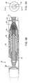
- FIG. 1is a perspective view of a debulking catheter of the present invention
- FIG. 3Ais an end view of the distal portion of the debulking catheter of FIG. 1 in which the cutter is in a closed position in the catheter body;
- FIG. 3Bis a sectional view along Line A-A of FIG. 3A ;
- FIGS. 3C and 3Dare views of the distal portion of a debulking catheter, where the distal portion has a locking shuttle mechanism
- FIG. 4Ais an end view of the distal portion of the debulking catheter of FIG. 1 in which the cutter is in an open position outside of the cutting window;
- FIG. 4Bis a sectional view along Line A-A of FIG. 4A ;
- FIG. 5Ais an end view of the distal portion of the debulking catheter of FIG. 1 in which the cutter is in a packing position within a tip of the catheter;
- FIG. 10Ais a perspective view of a in-stent restenosis cutter of the present invention.
- FIG. 10Cis a sectional view of the cutter along Line B-B of the cutter of FIGS. 10A and 10B ;
- FIG. 11Cis a sectional view of the cutter along Line C-C of the cutter of FIGS. 11A and 11B ;
- FIG. 11Dis a side view of another embodiment of a cutter, shown partially within a catheter body
- Catheter bodies intended for intravascular introductionwill typically have a length in the range from 50 cm to 200 cm and an outer diameter in the range from 1 French to 12 French (0.33 mm: 1 French), usually from 3 French to 9 French.
- the lengthis typically in the range from 125 cm to 200 cm, the diameter is preferably below 8 French, more preferably below 7 French, and most preferably in the range from 2 French to 7 French.
- Catheter bodieswill typically be composed of an organic polymer which is fabricated by conventional extrusion techniques. Suitable polymers include polyvinylchloride, polyurethanes, polyesters, polytetrafluoroethylenes (PTFE), silicone rubbers, natural rubbers, and the like.
- a rigid distal portion of a catheter bodycan be formed from materials which are rigid or which have very low flexibilities, such as metals, hard plastics, composite materials, NiTi, steel with a coating such as titanium nitride, tantalum, ME-92®, diamonds, or the like. Most usually, the distal end of the catheter body will be formed from stainless steel or platinum/iridium.
- the length of the rigid distal portionmay vary widely, typically being in the range from 5 mm to 35 mm, more usually from 10 mm to 25 mm, and preferably between 6 mm and 8 mm. In contrast, conventional catheters typically have rigid lengths of approximately 16 mm.
- activation of an input devicecan deflect a distal portion of the catheter relative to the proximal portion of the catheter.
- Angular deflection of the distal portionmay serve one or more purposes in various embodiments.
- deflection of the distal portionincreases the effective “diameter” of the catheter and causes the debulking assembly to be urged against material in a lumen, such as arteriosclerotic plaque.
- deflection of the distal portionmay act to expose a debulking assembly through a window for contacting material in a lumen.
- activation of the input devicemoves the debulking assembly over a ramp or cam so that a portion of the rigid distal portion and flexible tip are caused to drop out of the path of the debulking assembly so as to expose the debulking assembly through the window.
- deflectionmay both urge a portion of the catheter into material in a lumen and expose a tissue debulking assembly.
- the debulking assemblycomprises a rotatable cutter that is movable outside the window.
- the cutterBy moving the cutter outside of the cutting window beyond an outer diameter of the distal portion of the catheter, the cutter is able to contact and sever material that does not invaginate the cutting window.
- the rotating cuttercan be moved over the cam within the rigid, or distal, portion of the catheter body so that the cutting edge is moved out of the window. Moving the rotating cutter outside of the Cutting window and advancing the entire catheter body distally, a large amount of occlusive material can be removed. Consequently, the amount of material that can be removed is not limited by the size of the cutting window.
- the distal lumenmay have a length of between about 2.0 cm and about 3.0 cm and the proximal lumen may have a length of between about 10 cm and about 14 cm.
- a distal tip guidewire lumenmay be configured to telescope within a proximal guidewire lumen, or vice versa.
- a telescoping guidewire lumenmay enhance performance of the catheter by preventing a guidewire from being exposed within a body lumen.
- the present inventionmay optionally employ any of a wide variety of conventional radiopaque markers, imaging devices, and/or transducers.
- the catheters of the present inventioncan include a radiopaque distal portion and/or radiopaque markers disposed on a distal portion of the catheter body, such as proximal and distal of the cutting window, on the cam or ramp, so as to allow the user to track the position of the cutter, or the like.
- the catheters of the present inventionwill also be particularly useful with ultrasonic transducers, such as an IVUS, of a type which may be deployed linearly within the catheter body or circumferentially on the debulking assembly.
- a debulking assemblysuch as a cutter 28 , abrasive member, or the like, is disposed within a lumen 30 of the catheter body 22 .
- the cutter 28is typically rotatable within the distal portion 26 about an axis that is parallel to the longitudinal axis of the distal portion 26 of catheter 20 and axially movable along the longitudinal axis.
- the cutter 28can access target tissue through a side opening window 32 which is typically large enough to allow the cutter 28 to protrude through and move out of the window 32 a predetermined distance.
- the cutteris coupled to a cutter driver 34 through a coiled drive shaft 36 .
- Actuation of a movable actuator or other input device 38can activate the drive shaft 36 and cutter, move cutter 28 longitudinally over a cam so as to deflect the distal portion and move the cutter 28 out of cutting window 32 .
- Cramming of the cutter 28can cause the distal portion 26 to pivot or deflect relative to the proximal portion 24 so as to deflect and urge the cutter into the tissue in the body lumen.
- the distal portion 26 of the cathetermay be moved to an angled or offset configuration from the longitudinal axis of the proximal portion 24 of the catheter and the cutter 28 .
- the cutter 28can also be deflected off of the axis of the proximal and/or distal portion of the catheter. Moving the distal portion 26 to an angled/offset position may cause a portion of the catheter to urge against a target tissue, may expose the cutter 28 through the window 32 or both, in various embodiments.
- proximal portion 24is typically relatively flexible and distal portion 26 is typically relatively rigid. Additionally, many embodiments include a flexible distal tip 42 .
- the flexible proximal portion 24 of the catheteris typically a torque shaft and the distal portion 26 is typically a rigid tubing.
- the torque shaft 24facilitates transportation of the catheter body 22 and cutter 28 to the diseased site.
- the proximal end of the torque shaft 24is coupled to a proximal handle 40 and the distal end of the torque shaft is attached to the distal, rigid portion 26 of the catheter through the connection assembly 27 .
- the drive shaft 36is movably positioned within the torque shaft 24 so as to rotate and axially move within the torque shaft 24 .
- the drive shaft 36 and torque shaft 24are sized to allow relative movement of each shaft without interfering with the movement of the other shaft.
- the catheter bodywill have the pushability and torqueability such that torquing and pushing of the proximal end will translate motion to the distal portion 26 of the catheter body 22 .
- some embodimentsmay include a distal guidewire lumen having a length of between about 1.0 cm and about 5.0 cm, and preferably between about 2.0 cm and about 3.0 cm.
- a distal guidewire lumenmay be used alone or in conjunction with a proximal guidewire lumen located on another, more proximal, portion of the catheter 20 .
- the distal lumenmay be configured to partially telescope within a portion of the proximal guidewire lumen, or vice versa.
- Such telescoping lumensmay be used in embodiments where the distal portion 26 of catheter body 22 is movable relative to the proximal portion 24 .
- a telescoping lumenmay enhance performance of the catheter 20 by allowing a guidewire to be maintained largely within a lumen and to not be exposed within the body lumen being treated.
- Telescoping lumensmay have any suitable diameters and configurations to allow for sliding or otherwise fitting of one lumen within another.
- the cathetercan also include a shaft adaptor 50 and collar 52 to couple articulation member 48 to the torque shaft 22 .
- Shaft adaptor 50can connect the housing to the torque shaft and collar 52 can be placed over a proximal end of the shaft adaptor and crimped for a secure attachment.
- other catheters of the present inventionmay not include more or fewer of the components described above.
- some componentscan be made integral with other components and some components may be left out entirely.
- the rampmay be integrated with the distal tip to direct the cutter out of the cutting window.
- the cutters 28 of the present inventionwill generally be movable between two or more positions. During advancement through the body lumen, the cutter will generally be in a neutral position ( FIGS. 3A and 3B ) in which the cutter 28 is distal of cutting window 32 . In some embodiments, an imaging device (not shown) can be coupled to cutter 28 so as to image the body lumen through cutting window 32 when cutter 28 is in the neutral position.
- the cutter 28can be moved to an open position ( FIGS. 4A and 4B ) in which the cutter 28 is moved to a proximal end of the cutting window 32 and will extend out of the cutting window 32 a distance L 1 beyond an outer diameter D of the rigid portion 26 . In most embodiments, in the open position, the cutter will have deflected the distal portion and the cutter's axis of rotation will generally be in line with connection assembly 27 but angled or offset from longitudinal axis of the distal portion of the catheter body.
- a jointis located proximal to the cutting window 32 to provide a pivot point for cramming of the distal portion 26 relative to the proximal portion 24 .
- the bending at a flexible joint 49is caused by the interaction of cams or ramps 44 with cutter 28 and the tensile force provided through drive shaft 36 .
- the jointincludes a housing adaptor 46 that is pivotally coupled to the distal rigid portion 26 .
- the resulting pivoting of the rigid distal portion 26 relative to the proximal portioncauses a cramming effect which urges the distal housing against the body lumen wall without the use of urging means (e.g., a balloon) that is positioned opposite of the cutting window.
- urging meanse.g., a balloon
- the deflection of the distal portion 26 of the catheterurges the cutter into position such that distal advancement of the entire catheter body can move the rotating cutter through the occlusive material. Because the cutter is moved a distance L 1 beyond the outer diameter of the distal portion of the catheter and outside of the cutting window, the user does not have to invaginate the tissue into the cutting window. In some embodiments, for example, the cutter can be moved between about 0.025 mm and about 1.016 mm, and preferably between about 0.025 mm and about 0.64 mm, beyond the outer dimension of the distal housing. It should be appreciated that the cutter excursion directly relates to the depth of cut. The higher the cutter moves out of the cutting window the deeper the cut. The ranges are chosen around efficacy without risk of perforation of the body lumen.
- Pushing the entire catheter across a lesionremoves all or a portion of the lesion from the body lumen.
- Severed tissue from the lesionis collected by directing it into a collection chamber 53 in the tip via the cutter 28 .
- the cutter 28can be advanced distally to a “part off position” in which the cutter is moved back into the cutting window 32 ( FIG. 3B ).
- the tissueis collected as the severed pieces of tissue are directed into a collection chamber 53 via the distal movement of cutter 28 and catheter.
- the collection chamber 53 of the tip and distal portion 26acts as a receptacle for the severed material, to prevent the severed occlusive material from entering the body lumen and possibly causing downstream occlusions.
- enhancements to the collection chamber 53may be included.
- the collection chamber 53may be configured to be partially or completely translucent or radiolucent and a portion of the catheter surrounding or adjacent to the window 32 will be radiopaque. This combination of radiolucent collection chamber 53 and radiopaque material adjacent window 32 will enhance the ability of a user to determine how full the collection chamber 53 is, because the fullness of the collection chamber will be directly related to the distance the cutter 28 can advance forward into the collection chamber 53 . By facilitating the assessment of collection chamber filling, these embodiments will reduce the need for manually withdrawing the catheter to examine the collection chamber 53 .
- the collection chamber 53may connect to the rigid housing by means of interlocking components, which interlock with complementary components on the rigid housing. Such components may resemble a screw-in configuration, for example. Interlocking components will provide a stable connection between the collection chamber 53 and the rigid housing while not increasing the outer diameter of either the chamber 53 or the housing.
- collection chamber 53may be given any suitable configuration, shape or size.
- collection chamber 53 in FIGS. 6-8has a helical configuration.
- collection chamber 53may include a series of circular members, straight linear members, one solid cylindrical or cone-shaped member or the like.
- FIGS. 6 through 8illustrate one exemplary monorail delivery system to assist in positioning the cutter 28 at the target site.
- tip 42 of the cathetercan include a lumen 54 having a distal opening 43 and a proximal opening 55 that is sized to receive a guidewire, having a diameter of about 0.014 in., about 0.018 in., about 0.032 in. or any other suitable diameter.
- the flexible proximal portion of the catheter bodymay also include a short lumen 56 (e.g., about 12 centimeters in length).
- the guidewire lumen 56may be disposed within or outside the flexible proximal portion of the catheter body and run a longer or shorter length, and in fact may run the entire length of the flexible portion 24 of the catheter body.
- the guidewirecan be disposed within lumen 56 on the flexible portion of the catheter body and exit the lumen at a point proximal to the rigid portion 26 of the catheter. The guidewire can then re-enter a proximal opening 55 in the tip lumen 54 and exit through distal opening 43 in the tip lumen.
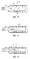
- This unattached portion 121(or “free floating lumen”) protects a guidewire from contacting a body lumen in which the device is used and also allows the device to be moved more freely, without bending or kinking the guidewire.
- the telescoping guidewire 124extends within the proximal lumen 126 at the distal opening 127 of proximal lumen 126 .
- the telescoping featureallows for movement of the catheter body while preventing or reducing bending of the guidewire.
- catheter 120allows for deflection of distal tip 122 and the distal portion of the catheter 120 relative to the proximal portion 123 , for example by movement about a pivot point 129 .
- Telescoping distal lumen 124 and proximal lumen 126allow for this movement by allowing distal lumen 124 to telescope within proximal lumen 126 .
- distal lumen 124protects a guide wire from exposure to a body lumen and/or bodily fluids.
- distal lumen 124 and proximal lumen 126may telescope within proximal lumen 126 by a distance of approximately 1 cm.
- a telescoping lumen 24may be longer than distal lumens in other embodiments.
- telescoping lumen 24may have a length of between about 2 cm and about 10 cm, and preferably between about 5 cm and about 8 cm.
- the outer diameter of telescoping distal lumen 124is configured to fit within the inner diameter of proximal lumen 126 .
- any combination of sizes, lengths, diameters and shapes of distal lumen 124 and proximal lumen 126may be used, to allow telescoping of one into another.
- FIGS. 9A through 11Dshow some exemplary embodiments of the cutter 28 of the present invention.
- the distal portion 60 of the rotatable cutter 28can include a serrated knife edge 62 or a smooth knife edge 64 and a curved or scooped distal surface 66 .
- the distal portion 60may have any suitable diameter or height. In some embodiments, for example, the diameter across the distal portion 60 may be between about 0.1 cm and about 0.2 cm.
- a proximal portion 68 of the cutter 28can include a channel 70 that can be coupled to the drive shaft 36 that rotates the cutter. As shown in FIGS.
- FIGS. 12 through 16illustrate an exemplary cutter driver 34 of the present invention.
- cutter driver 34can act as the handle for the user to manipulate the catheters 20 of the present invention as well as a power source.
- the cutter drivers 34 of the present inventioninclude a single input device, such as a lever 38 that controls the major operations of the catheter (e.g., axial movement to cause urging, rotation to cause cutting, and axial movement for packing).
- cutter driver 34includes a power source 72 (e.g., batteries), a motor 74 , a microswitch 76 for activating motor 74 , and a connection assembly (not shown) for connecting the drive shaft 36 to the driver motor 74 .
- the drive motorcan rotate drive shaft 36 between 1,000 rpm and 10,000 rpm or more, if desired.
- FIGS. 14 through 16illustrate one exemplary method of operating cutter driver 34 .
- the catheterwill be delivered to the target site with cutter driver unattached and the cutter in the neutral position ( FIG. 3B ).
- the cutter drivercan be attached with the urge lever 38 in a neutral position ( FIG. 14 ), which indicates that the cutter is closed, but not in a 15 packing position.
- the usercan then move the catheter (and cutter driver unit, if desired) to position the distal portion 26 of the catheter adjacent the target tissue.
- the urge lever 38can be moved proximally from the neutral position to move the cutter proximally and out of cutting window 32 ( FIG. 4B ) and simultaneously depressing microswitch 76 to activate motor 74 .
- cutter driver 34provides an automatic on/off control of the cutter 28 that is keyed to the position of the cutter. Such a configuration frees the user from the complicated task of remembering the sequence of operations to activate and deactivate the rotation and axial movement of the cutter.
- cutter driver 34is illustrated as a disposable battery powered unit, it should be appreciated that in other embodiments, the cutter driver can use other power sources to control the cutter driver. It should further be appreciated that other cutter drivers can be used with the present invention. While not preferred, it is possible to have separate controls to control the axial movement of the cutter and the rotation of the cutter.
- One method of the present inventioncomprises delivering a catheter to a target site in the body lumen.
- a distal portion of the cathetercan be deflected relative to a proximal portion of the catheter to expose a tissue debulking device in the catheter.
- the body lumencan be debulked with the exposed debulking device.
- one specific methodcomprises advancing a catheter to a target site (Step 100 ).
- a cuttercan be rotated and moved out of the cutting window (Steps 102 , 104 ).
- a distal portion of the cathetercan be pivoted or deflected so as to position the cutter adjacent the target material.
- the catheter and the rotating cuttercan be moved through the body lumen to remove the target material from the body lumen (Step 106 ).
- the cutter 28will be retracted proximally and moved out of cutting window 32 to its second, exposed position.
- movement of the cuttercan deflect the distal portion of the catheter to increase the profile of the catheter at the target site. Movement of the cutter is typically caused by proximal movement of lever 38 and tensioning of drive shaft 36 . Movement of the lever can be scaled to any desired ratio or a direct 1:1 ratio of movement between the handle and cutter.
- the cutterWhen the cutter is moved proximally it contacts ramp or cam surfaces so as to guide the cutter tip and at least partially out of the cutting window 32 .
- the distal portion of catheter body 26rotates about the joint 49 to provide an urging force for the cutter (and catheter body) to move toward the diseased area.
- the operatorcan move the entire catheter body 22 through the lesion to dissect the tissue.
- tissue that is trapped between the cutting edge 52 and the cutting window 32is severed from the body lumen.
- the operatorcan stop pushing the device distally and the cutter can be advanced distally inside the cutting window by advancing the handle 38 .
- the cutter 28rides back over the ramps 44 and directs the cutter back inside of the cutting window 32 .
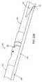
- Such movementcauses the distal portion 26 of the catheter to move in line with the cutter and proximal portion 24 ( FIG. 5B ).
- the cutterWhen the cutter has moved to its distal position, the cutter parts off the severed tissue and urges the severed tissue inside of a collection chamber 53 in the distal tip 42 .
- the lever 38 and thus the non-rotating cutter 38can be advanced distally to pack the tissue into the collection chamber 53 ( FIG. 5B ).
- Use of the cutter to pack the severed tissuewill allow the operator multiple specimens to be collected prior to removing the catheter 20 from the body lumen. When it is determined that the collection chamber is full, the catheter can be removed from the body lumen and the collection chamber can be emptied.
- an input deviceis disposed in a first position to position a tissue removal element in a neutral position (Step 120 ).
- the input deviceis activated to rotate the tissue removal element and to axially move the tissue removal device to an active position (Step 122 ).
- the input devicecan then be activated again to move the tissue removal element to a packing position (Step 124 ).
- the input deviceis a lever or thumb switch that can be moved to correspond to the movement of a cutting element on the catheter.
- the leveris moved proximally, the cutter is rotated and moved proximally to an open position.
- the rotation of the cuttercan be stopped and the cutter can be moved distally to pack severed tissue into a collection chamber.
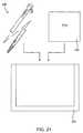
- kitsincluding catheters 200 , instructions for use 202 , and packages 204 .
- Catheters 200will generally be as described above, and the instruction for use (IFU) 202 will set forth any of the methods described above.
- Package 204may be any conventional medical device packaging, including pouches, trays, boxes, tubes, or the like.
- the instructions for use 202will usually be printed on a separate piece of paper, but may also be printed in whole or in part on a portion of the packaging 204 .
- the cathetercan include a shape memory material such that the catheter forms a jog or a pre-bent shape when it reaches its target area.
Landscapes
- Health & Medical Sciences (AREA)
- Surgery (AREA)
- Life Sciences & Earth Sciences (AREA)
- Biomedical Technology (AREA)
- Nuclear Medicine, Radiotherapy & Molecular Imaging (AREA)
- Engineering & Computer Science (AREA)
- Vascular Medicine (AREA)
- Heart & Thoracic Surgery (AREA)
- Medical Informatics (AREA)
- Molecular Biology (AREA)
- Animal Behavior & Ethology (AREA)
- General Health & Medical Sciences (AREA)
- Public Health (AREA)
- Veterinary Medicine (AREA)
- Surgical Instruments (AREA)
Abstract
Description
Claims (20)
Priority Applications (7)
| Application Number | Priority Date | Filing Date | Title |
|---|---|---|---|
| US10/288,581US7887556B2 (en) | 2000-12-20 | 2002-11-04 | Debulking catheters and methods |
| US10/421,980US20040167554A1 (en) | 2000-12-20 | 2003-04-22 | Methods and devices for reentering a true lumen from a subintimal space |
| US10/421,979US7713279B2 (en) | 2000-12-20 | 2003-04-22 | Method and devices for cutting tissue |
| US12/431,210US8998937B2 (en) | 1999-08-19 | 2009-04-28 | Methods and devices for cutting tissue |
| US13/940,430US9486237B2 (en) | 1999-08-19 | 2013-07-12 | Methods and devices for cutting tissue |
| US14/656,881US9532799B2 (en) | 1999-08-19 | 2015-03-13 | Method and devices for cutting tissue |
| US15/270,147US10022145B2 (en) | 1999-08-19 | 2016-09-20 | Methods and devices for cutting tissue |
Applications Claiming Priority (5)
| Application Number | Priority Date | Filing Date | Title |
|---|---|---|---|
| US25770400P | 2000-12-20 | 2000-12-20 | |
| US27227301P | 2001-02-27 | 2001-02-27 | |
| US10/027,418US7771444B2 (en) | 2000-12-20 | 2001-12-19 | Methods and devices for removing material from a body lumen |
| US38163202P | 2002-05-17 | 2002-05-17 | |
| US10/288,581US7887556B2 (en) | 2000-12-20 | 2002-11-04 | Debulking catheters and methods |
Related Parent Applications (2)
| Application Number | Title | Priority Date | Filing Date |
|---|---|---|---|
| US10/027,418Continuation-In-PartUS7771444B2 (en) | 1999-08-19 | 2001-12-19 | Methods and devices for removing material from a body lumen |
| US10/027,418ContinuationUS7771444B2 (en) | 1999-08-19 | 2001-12-19 | Methods and devices for removing material from a body lumen |
Related Child Applications (2)
| Application Number | Title | Priority Date | Filing Date |
|---|---|---|---|
| US10/421,979Continuation-In-PartUS7713279B2 (en) | 1999-08-19 | 2003-04-22 | Method and devices for cutting tissue |
| US10/421,980Continuation-In-PartUS20040167554A1 (en) | 2000-12-20 | 2003-04-22 | Methods and devices for reentering a true lumen from a subintimal space |
Publications (2)
| Publication Number | Publication Date |
|---|---|
| US20030125758A1 US20030125758A1 (en) | 2003-07-03 |
| US7887556B2true US7887556B2 (en) | 2011-02-15 |
Family
ID=46281475
Family Applications (1)
| Application Number | Title | Priority Date | Filing Date |
|---|---|---|---|
| US10/288,581Expired - Fee RelatedUS7887556B2 (en) | 1999-08-19 | 2002-11-04 | Debulking catheters and methods |
Country Status (1)
| Country | Link |
|---|---|
| US (1) | US7887556B2 (en) |
Cited By (27)
| Publication number | Priority date | Publication date | Assignee | Title |
|---|---|---|---|---|
| US8192452B2 (en) | 2009-05-14 | 2012-06-05 | Tyco Healthcare Group Lp | Easily cleaned atherectomy catheters and methods of use |
| US8226674B2 (en) | 2000-12-20 | 2012-07-24 | Tyco Healthcare Group Lp | Debulking catheters and methods |
| US8246640B2 (en) | 2003-04-22 | 2012-08-21 | Tyco Healthcare Group Lp | Methods and devices for cutting tissue at a vascular location |
| US8328829B2 (en) | 1999-08-19 | 2012-12-11 | Covidien Lp | High capacity debulking catheter with razor edge cutting window |
| US8414604B2 (en) | 2008-10-13 | 2013-04-09 | Covidien Lp | Devices and methods for manipulating a catheter shaft |
| US8469979B2 (en) | 2000-12-20 | 2013-06-25 | Covidien Lp | High capacity debulking catheter with distal driven cutting wheel |
| US8496677B2 (en) | 2009-12-02 | 2013-07-30 | Covidien Lp | Methods and devices for cutting tissue |
| US8597315B2 (en) | 1999-08-19 | 2013-12-03 | Covidien Lp | Atherectomy catheter with first and second imaging devices |
| US8784440B2 (en) | 2008-02-25 | 2014-07-22 | Covidien Lp | Methods and devices for cutting tissue |
| US8808186B2 (en) | 2010-11-11 | 2014-08-19 | Covidien Lp | Flexible debulking catheters with imaging and methods of use and manufacture |
| US8920450B2 (en) | 2010-10-28 | 2014-12-30 | Covidien Lp | Material removal device and method of use |
| US8992717B2 (en) | 2011-09-01 | 2015-03-31 | Covidien Lp | Catheter with helical drive shaft and methods of manufacture |
| US8998937B2 (en) | 1999-08-19 | 2015-04-07 | Covidien Lp | Methods and devices for cutting tissue |
| US9028512B2 (en) | 2009-12-11 | 2015-05-12 | Covidien Lp | Material removal device having improved material capture efficiency and methods of use |
| US9119662B2 (en) | 2010-06-14 | 2015-09-01 | Covidien Lp | Material removal device and method of use |
| US20160206345A1 (en)* | 2013-09-30 | 2016-07-21 | Cordynamix, Inc. | Methods and devices for diastolic assist |
| US9532844B2 (en) | 2012-09-13 | 2017-01-03 | Covidien Lp | Cleaning device for medical instrument and method of use |
| US20170164968A1 (en)* | 2013-12-03 | 2017-06-15 | Michael D. Laufer | Methods and devices for diastolic assist |
| US9687266B2 (en) | 2009-04-29 | 2017-06-27 | Covidien Lp | Methods and devices for cutting and abrading tissue |
| US9801647B2 (en) | 2006-05-26 | 2017-10-31 | Covidien Lp | Catheter including cutting element and energy emitting element |
| US9943330B2 (en) | 2015-09-10 | 2018-04-17 | Covidien Lp | Tissue-removing catheter with asymmetric window |
| US9943329B2 (en) | 2012-11-08 | 2018-04-17 | Covidien Lp | Tissue-removing catheter with rotatable cutter |
| US10213224B2 (en) | 2014-06-27 | 2019-02-26 | Covidien Lp | Cleaning device for catheter and catheter including the same |
| US10292721B2 (en) | 2015-07-20 | 2019-05-21 | Covidien Lp | Tissue-removing catheter including movable distal tip |
| US10314664B2 (en) | 2015-10-07 | 2019-06-11 | Covidien Lp | Tissue-removing catheter and tissue-removing element with depth stop |
| US10314667B2 (en) | 2015-03-25 | 2019-06-11 | Covidien Lp | Cleaning device for cleaning medical instrument |
| US10772678B2 (en) | 2013-09-30 | 2020-09-15 | Michael D. Laufer | Methods and devices for diastolic assist |
Families Citing this family (62)
| Publication number | Priority date | Publication date | Assignee | Title |
|---|---|---|---|---|
| US20030120295A1 (en)* | 2000-12-20 | 2003-06-26 | Fox Hollow Technologies, Inc. | Debulking catheters and methods |
| US7887556B2 (en) | 2000-12-20 | 2011-02-15 | Fox Hollow Technologies, Inc. | Debulking catheters and methods |
| US6638233B2 (en) | 1999-08-19 | 2003-10-28 | Fox Hollow Technologies, Inc. | Apparatus and methods for material capture and removal |
| US20030125757A1 (en)* | 2000-12-20 | 2003-07-03 | Fox Hollow Technologies, Inc. | Debulking catheters and methods |
| US20040167554A1 (en)* | 2000-12-20 | 2004-08-26 | Fox Hollow Technologies, Inc. | Methods and devices for reentering a true lumen from a subintimal space |
| US7927784B2 (en)* | 2000-12-20 | 2011-04-19 | Ev3 | Vascular lumen debulking catheters and methods |
| US7699790B2 (en) | 2000-12-20 | 2010-04-20 | Ev3, Inc. | Debulking catheters and methods |
| US20060235366A1 (en)* | 2000-12-20 | 2006-10-19 | Fox Hollow Technologies, Inc. | Method of evaluating a treatment for vascular disease |
| US7794413B2 (en)* | 2005-04-19 | 2010-09-14 | Ev3, Inc. | Libraries and data structures of materials removed by debulking catheters |
| US20070038173A1 (en)* | 2005-07-27 | 2007-02-15 | Fox Hollow Technologies, Inc. | Methods affecting markers in patients having vascular disease |
| US7989207B2 (en)* | 2006-02-17 | 2011-08-02 | Tyco Healthcare Group Lp | Testing lumenectomy samples for markers of non-vascular diseases |
| US7981128B2 (en)* | 2006-06-30 | 2011-07-19 | Atheromed, Inc. | Atherectomy devices and methods |
| US8007506B2 (en) | 2006-06-30 | 2011-08-30 | Atheromed, Inc. | Atherectomy devices and methods |
| US20080045986A1 (en) | 2006-06-30 | 2008-02-21 | Atheromed, Inc. | Atherectomy devices and methods |
| US9492192B2 (en) | 2006-06-30 | 2016-11-15 | Atheromed, Inc. | Atherectomy devices, systems, and methods |
| AU2007269274A1 (en) | 2006-06-30 | 2008-01-10 | Atheromed, Inc. | Atherectomy devices and methods |
| US8628549B2 (en) | 2006-06-30 | 2014-01-14 | Atheromed, Inc. | Atherectomy devices, systems, and methods |
| US8361094B2 (en)* | 2006-06-30 | 2013-01-29 | Atheromed, Inc. | Atherectomy devices and methods |
| US20090018566A1 (en) | 2006-06-30 | 2009-01-15 | Artheromed, Inc. | Atherectomy devices, systems, and methods |
| US9314263B2 (en)* | 2006-06-30 | 2016-04-19 | Atheromed, Inc. | Atherectomy devices, systems, and methods |
| US8236016B2 (en) | 2007-10-22 | 2012-08-07 | Atheromed, Inc. | Atherectomy devices and methods |
| US8070762B2 (en)* | 2007-10-22 | 2011-12-06 | Atheromed Inc. | Atherectomy devices and methods |
| US9125562B2 (en) | 2009-07-01 | 2015-09-08 | Avinger, Inc. | Catheter-based off-axis optical coherence tomography imaging system |
| US9788790B2 (en) | 2009-05-28 | 2017-10-17 | Avinger, Inc. | Optical coherence tomography for biological imaging |
| US8696695B2 (en) | 2009-04-28 | 2014-04-15 | Avinger, Inc. | Guidewire positioning catheter |
| US20100125253A1 (en)* | 2008-11-17 | 2010-05-20 | Avinger | Dual-tip Catheter System for Boring through Blocked Vascular Passages |
| US8062316B2 (en) | 2008-04-23 | 2011-11-22 | Avinger, Inc. | Catheter system and method for boring through blocked vascular passages |
| WO2011003006A2 (en) | 2009-07-01 | 2011-01-06 | Avinger, Inc. | Atherectomy catheter with laterally-displaceable tip |
| WO2011072068A2 (en) | 2009-12-08 | 2011-06-16 | Avinger, Inc. | Devices and methods for predicting and preventing restenosis |
| US11382653B2 (en) | 2010-07-01 | 2022-07-12 | Avinger, Inc. | Atherectomy catheter |
| US10548478B2 (en) | 2010-07-01 | 2020-02-04 | Avinger, Inc. | Balloon atherectomy catheters with imaging |
| WO2014039096A1 (en) | 2012-09-06 | 2014-03-13 | Avinger, Inc. | Re-entry stylet for catheter |
| US9345510B2 (en) | 2010-07-01 | 2016-05-24 | Avinger, Inc. | Atherectomy catheters with longitudinally displaceable drive shafts |
| US9949754B2 (en) | 2011-03-28 | 2018-04-24 | Avinger, Inc. | Occlusion-crossing devices |
| EP2691038B1 (en) | 2011-03-28 | 2016-07-20 | Avinger, Inc. | Occlusion-crossing devices, imaging, and atherectomy devices |
| WO2013056262A1 (en) | 2011-10-13 | 2013-04-18 | Atheromed, Inc. | Atherectomy apparatus, systems and methods |
| EP3653151A1 (en) | 2011-10-17 | 2020-05-20 | Avinger, Inc. | Atherectomy catheters and non-contact actuation mechanism for catheters |
| US9345406B2 (en) | 2011-11-11 | 2016-05-24 | Avinger, Inc. | Occlusion-crossing devices, atherectomy devices, and imaging |
| EP2849660B1 (en) | 2012-05-14 | 2021-08-25 | Avinger, Inc. | Atherectomy catheter drive assemblies |
| US9557156B2 (en) | 2012-05-14 | 2017-01-31 | Avinger, Inc. | Optical coherence tomography with graded index fiber for biological imaging |
| WO2013172970A1 (en) | 2012-05-14 | 2013-11-21 | Avinger, Inc. | Atherectomy catheters with imaging |
| US9498247B2 (en) | 2014-02-06 | 2016-11-22 | Avinger, Inc. | Atherectomy catheters and occlusion crossing devices |
| US11284916B2 (en) | 2012-09-06 | 2022-03-29 | Avinger, Inc. | Atherectomy catheters and occlusion crossing devices |
| WO2014093148A2 (en)* | 2012-12-12 | 2014-06-19 | Covidien Lp | Tissue-removing catheter for body lumen |
| EP2931151B1 (en)* | 2012-12-12 | 2019-11-27 | Covidien LP | Tissue-removing catheter including urging mechanism |
| CN105228514B (en) | 2013-03-15 | 2019-01-22 | 阿维格公司 | Optical Pressure Sensor Assembly |
| US11096717B2 (en) | 2013-03-15 | 2021-08-24 | Avinger, Inc. | Tissue collection device for catheter |
| WO2014143064A1 (en) | 2013-03-15 | 2014-09-18 | Avinger, Inc. | Chronic total occlusion crossing devices with imaging |
| EP3019096B1 (en) | 2013-07-08 | 2023-07-05 | Avinger, Inc. | System for identification of elastic lamina to guide interventional therapy |
| MX2016010141A (en) | 2014-02-06 | 2017-04-06 | Avinger Inc | Atherectomy catheters and occlusion crossing devices. |
| US10357277B2 (en) | 2014-07-08 | 2019-07-23 | Avinger, Inc. | High speed chronic total occlusion crossing devices |
| US10568520B2 (en) | 2015-07-13 | 2020-02-25 | Avinger, Inc. | Micro-molded anamorphic reflector lens for image guided therapeutic/diagnostic catheters |
| JP6927986B2 (en) | 2016-01-25 | 2021-09-01 | アビンガー・インコーポレイテッドAvinger, Inc. | OCT imaging catheter with delay compensation |
| EP3435892B1 (en) | 2016-04-01 | 2024-04-03 | Avinger, Inc. | Atherectomy catheter with serrated cutter |
| US11344327B2 (en) | 2016-06-03 | 2022-05-31 | Avinger, Inc. | Catheter device with detachable distal end |
| WO2018006041A1 (en) | 2016-06-30 | 2018-01-04 | Avinger, Inc. | Atherectomy catheter with shapeable distal tip |
| US12167867B2 (en) | 2018-04-19 | 2024-12-17 | Avinger, Inc. | Occlusion-crossing devices |
| CN114746033B (en) | 2019-10-18 | 2025-01-10 | 阿维格公司 | Blocking crossing device |
| US11304723B1 (en) | 2020-12-17 | 2022-04-19 | Avantec Vascular Corporation | Atherectomy devices that are self-driving with controlled deflection |
| JP2024518961A (en) | 2021-06-07 | 2024-05-08 | アバンテック バスキュラー コーポレイション | Hybrid Atherectomy Device |
| US12220140B1 (en) | 2023-08-16 | 2025-02-11 | Avantec Vascular Corporation | Thrombectomy devices with lateral and vertical bias |
| US12414785B1 (en) | 2025-03-17 | 2025-09-16 | Avantec Vascular Corporation | Cutters with pulsating vacuum control |
Citations (168)
| Publication number | Priority date | Publication date | Assignee | Title |
|---|---|---|---|---|
| US2178790A (en) | 1938-05-07 | 1939-11-07 | Abner E Henry | Cutting implement |
| US3705577A (en) | 1969-10-02 | 1972-12-12 | Rafael B Sierra | Biopsy needle with eccentrically-mounted cutting tip |
| US3815604A (en) | 1972-06-19 | 1974-06-11 | Malley C O | Apparatus for intraocular surgery |
| US3837345A (en) | 1973-08-31 | 1974-09-24 | A Matar | Venous valve snipper |
| US3995619A (en) | 1975-10-14 | 1976-12-07 | Glatzer Stephen G | Combination subcutaneous suture remover, biopsy sampler and syringe |
| US4034744A (en) | 1975-11-13 | 1977-07-12 | Smith Kline Instruments, Inc. | Ultrasonic scanning system with video recorder |
| US4210146A (en) | 1978-06-01 | 1980-07-01 | Anton Banko | Surgical instrument with flexible blade |
| US4349032A (en) | 1978-12-15 | 1982-09-14 | Olympus Optical Co., Ltd. | Endoscope with an ultrasonic probe |
| US4669469A (en) | 1986-02-28 | 1987-06-02 | Devices For Vascular Intervention | Single lumen atherectomy catheter device |
| US4696298A (en) | 1985-11-19 | 1987-09-29 | Storz Instrument Company | Vitrectomy cutting mechanism |
| US4771774A (en) | 1986-02-28 | 1988-09-20 | Devices For Vascular Intervention, Inc. | Motor drive unit |
| US4781186A (en) | 1984-05-30 | 1988-11-01 | Devices For Vascular Intervention, Inc. | Atherectomy device having a flexible housing |
| US4817613A (en) | 1987-07-13 | 1989-04-04 | Devices For Vascular Intervention, Inc. | Guiding catheter |
| US4819635A (en) | 1987-09-18 | 1989-04-11 | Henry Shapiro | Tubular microsurgery cutting apparatus |
| US4850957A (en) | 1988-01-11 | 1989-07-25 | American Biomed, Inc. | Atherectomy catheter |
| US4886061A (en) | 1988-02-09 | 1989-12-12 | Medinnovations, Inc. | Expandable pullback atherectomy catheter system |
| US4926858A (en) | 1984-05-30 | 1990-05-22 | Devices For Vascular Intervention, Inc. | Atherectomy device for severe occlusions |
| US4936987A (en) | 1983-03-07 | 1990-06-26 | Calgon Corporation | Synergistic scale and corrosion inhibiting admixtures containing carboxylic acid/sulfonic acid polymers |
| USRE33258E (en) | 1984-07-23 | 1990-07-10 | Surgical Dynamics Inc. | Irrigating, cutting and aspirating system for percutaneous surgery |
| US4954338A (en) | 1987-08-05 | 1990-09-04 | Rohm And Haas Company | Microbicidal microemulsion |
| US4966604A (en)* | 1989-01-23 | 1990-10-30 | Interventional Technologies Inc. | Expandable atherectomy cutter with flexibly bowed blades |
| US4973409A (en) | 1988-09-21 | 1990-11-27 | Ciba-Geigy Corporation | Treatment of aqueous systems |
| US4979951A (en)* | 1984-05-30 | 1990-12-25 | Simpson John B | Atherectomy device and method |
| US4986807A (en)* | 1989-01-23 | 1991-01-22 | Interventional Technologies, Inc. | Atherectomy cutter with radially projecting blade |
| US4994067A (en) | 1989-02-17 | 1991-02-19 | American Biomed, Inc. | Distal atherectomy catheter |
| US5000185A (en) | 1986-02-28 | 1991-03-19 | Cardiovascular Imaging Systems, Inc. | Method for intravascular two-dimensional ultrasonography and recanalization |
| US5024651A (en) | 1984-05-14 | 1991-06-18 | Surgical Systems & Instruments, Inc. | Atherectomy system with a sleeve |
| US5024234A (en) | 1989-10-17 | 1991-06-18 | Cardiovascular Imaging Systems, Inc. | Ultrasonic imaging catheter with guidewire channel |
| US5047040A (en) | 1987-11-05 | 1991-09-10 | Devices For Vascular Intervention, Inc. | Atherectomy device and method |
| US5053044A (en)* | 1988-01-11 | 1991-10-01 | Devices For Vascular Intervention, Inc. | Catheter and method for making intravascular incisions |
| US5054492A (en) | 1990-12-17 | 1991-10-08 | Cardiovascular Imaging Systems, Inc. | Ultrasonic imaging catheter having rotational image correlation |
| US5071425A (en) | 1988-09-12 | 1991-12-10 | Devices For Vascular Intervention, Inc. | Atherectomy catheter and method of forming the same |
| US5084010A (en) | 1990-02-20 | 1992-01-28 | Devices For Vascular Intervention, Inc. | System and method for catheter construction |
| US5085662A (en) | 1989-11-13 | 1992-02-04 | Scimed Life Systems, Inc. | Atherectomy catheter and related components |
| US5087265A (en) | 1989-02-17 | 1992-02-11 | American Biomed, Inc. | Distal atherectomy catheter |
| US5092873A (en) | 1990-02-28 | 1992-03-03 | Devices For Vascular Intervention, Inc. | Balloon configuration for atherectomy catheter |
| US5110822A (en) | 1991-01-03 | 1992-05-05 | Rohm And Haas Company | Synergistic combinations of 4,5-dichloro-2-n-octyl-3-isothiazolone or 2-methyl-3-isothiazolone with ferric dimethyl dithiocarbamate fungicide |
| US5114399A (en) | 1990-10-01 | 1992-05-19 | Intramed Laboratories | Surgical device |
| US5154724A (en) | 1990-05-14 | 1992-10-13 | Andrews Winston A | Atherectomy catheter |
| US5181920A (en) | 1990-06-08 | 1993-01-26 | Devices For Vascular Intervention, Inc. | Atherectomy device with angioplasty balloon and method |
| US5183432A (en) | 1988-03-19 | 1993-02-02 | Nihonmatai Co., Ltd. | Floating body of sophisticated shape produced from a single sheet of film with a single sealing |
| US5217474A (en) | 1991-07-15 | 1993-06-08 | Zacca Nadim M | Expandable tip atherectomy method and apparatus |
| US5222966A (en) | 1990-02-28 | 1993-06-29 | Devices For Vascular Intervention, Inc. | Balloon connection and inflation lumen for atherectomy catheter |
| US5224949A (en) | 1992-01-13 | 1993-07-06 | Interventional Technologies, Inc. | Camming device |
| US5224488A (en) | 1992-08-31 | 1993-07-06 | Neuffer Francis H | Biopsy needle with extendable cutting means |
| US5226910A (en) | 1989-07-05 | 1993-07-13 | Kabushiki Kaisha Topcon | Surgical cutter |
| US5226909A (en) | 1989-09-12 | 1993-07-13 | Devices For Vascular Intervention, Inc. | Atherectomy device having helical blade and blade guide |
| US5242460A (en) | 1990-10-25 | 1993-09-07 | Devices For Vascular Intervention, Inc. | Atherectomy catheter having axially-disposed cutting edge |
| US5250059A (en) | 1992-01-22 | 1993-10-05 | Devices For Vascular Intervention, Inc. | Atherectomy catheter having flexible nose cone |
| US5250065A (en) | 1990-09-11 | 1993-10-05 | Mectra Labs, Inc. | Disposable lavage tip assembly |
| US5263928A (en) | 1991-06-14 | 1993-11-23 | Baxter International Inc. | Catheter and endoscope assembly and method of use |
| US5269793A (en) | 1989-07-20 | 1993-12-14 | Devices For Vascular Intervention, Inc. | Guide wire systems for intravascular catheters |
| US5282484A (en) | 1989-08-18 | 1994-02-01 | Endovascular Instruments, Inc. | Method for performing a partial atherectomy |
| US5285795A (en) | 1991-09-12 | 1994-02-15 | Surgical Dynamics, Inc. | Percutaneous discectomy system having a bendable discectomy probe and a steerable cannula |
| US5318528A (en) | 1993-04-13 | 1994-06-07 | Advanced Surgical Inc. | Steerable surgical devices |
| US5318032A (en) | 1992-02-05 | 1994-06-07 | Devices For Vascular Intervention | Guiding catheter having soft tip |
| US5321501A (en) | 1991-04-29 | 1994-06-14 | Massachusetts Institute Of Technology | Method and apparatus for optical imaging with means for controlling the longitudinal range of the sample |
| DE9303531U1 (en) | 1993-03-11 | 1994-07-14 | Redha, Falah, Dr., Kloten | Medical instrument |
| US5372601A (en) | 1993-03-30 | 1994-12-13 | Lary; Banning G. | Longitudinal reciprocating incisor |
| US5372602A (en) | 1992-11-30 | 1994-12-13 | Device For Vascular Intervention, Inc. | Method of removing plaque using catheter cutter with torque control |
| US5395313A (en) | 1993-08-13 | 1995-03-07 | Naves; Neil H. | Reciprocating arthroscopic shaver |
| US5419774A (en) | 1993-07-13 | 1995-05-30 | Scimed Life Systems, Inc. | Thrombus extraction device |
| US5429136A (en) | 1993-04-21 | 1995-07-04 | Devices For Vascular Intervention, Inc. | Imaging atherectomy apparatus |
| US5431673A (en) | 1989-02-17 | 1995-07-11 | American Biomed, Inc. | Distal atherectomy catheter |
| US5441510A (en) | 1993-09-01 | 1995-08-15 | Technology Development Center | Bi-axial cutter apparatus for catheter |
| US5444078A (en) | 1993-10-01 | 1995-08-22 | Rohm And Haas Company | Fully water-dilutable microemulsions |
| US5491524A (en) | 1994-10-05 | 1996-02-13 | Carl Zeiss, Inc. | Optical coherence tomography corneal mapping apparatus |
| US5505210A (en) | 1989-11-06 | 1996-04-09 | Mectra Labs, Inc. | Lavage with tissue cutting cannula |
| US5507760A (en) | 1993-11-09 | 1996-04-16 | Devices For Vascular Intervention, Inc. | Cutter device |
| US5507795A (en) | 1994-04-29 | 1996-04-16 | Devices For Vascular Intervention, Inc. | Catheter with perfusion system |
| US5507292A (en) | 1990-05-21 | 1996-04-16 | Cardiovascular Imaging Systems, Inc. | Intravascular catheter having combined imaging abrasion head |
| US5514115A (en) | 1993-07-07 | 1996-05-07 | Device For Vascular Intervention, Inc. | Flexible housing for intracorporeal use |
| US5527325A (en) | 1993-07-09 | 1996-06-18 | Device For Vascular Intervention, Inc. | Atherectomy catheter and method |
| DE4444166A1 (en) | 1994-12-12 | 1996-06-20 | Urotech Med Tech Gmbh | Flexible knife for surgical use |
| US5549601A (en) | 1994-10-11 | 1996-08-27 | Devices For Vascular Intervention, Inc. | Delivery of intracorporeal probes |
| US5571122A (en) | 1992-11-09 | 1996-11-05 | Endovascular Instruments, Inc. | Unitary removal of plaque |
| US5571130A (en) | 1994-10-04 | 1996-11-05 | Advanced Cardiovascular Systems, Inc. | Atherectomy and prostectomy system |
| US5584842A (en) | 1992-12-02 | 1996-12-17 | Intramed Laboratories, Inc. | Valvulotome and method of using |
| US5620447A (en) | 1993-01-29 | 1997-04-15 | Smith & Nephew Dyonics Inc. | Surgical instrument |
| US5624457A (en) | 1994-04-07 | 1997-04-29 | Devices For Vascular Intervention | Directional atherectomy device with flexible housing |
| US5626562A (en) | 1994-11-28 | 1997-05-06 | Devices For Vascular Intervention | Drug delivery catheter |
| US5632754A (en) | 1994-12-23 | 1997-05-27 | Devices For Vascular Intervention | Universal catheter with interchangeable work element |
| US5634464A (en) | 1992-10-05 | 1997-06-03 | Cardiovascular Imaging Systems Inc. | Method and apparatus for ultrasound imaging and atherectomy |
| US5643298A (en)* | 1992-11-09 | 1997-07-01 | Nordgren; Gregory N. | Intra-artery obstruction clearing apparatus and methods |
| US5643296A (en)* | 1994-12-16 | 1997-07-01 | Devices For Vasclar Intervention | Intravascular catheter with guiding structure |
| US5674232A (en) | 1990-06-05 | 1997-10-07 | Halliburton; Alexander George | Catheter and method of use thereof |
| US5695506A (en) | 1996-02-06 | 1997-12-09 | Devices For Vascular Intervention | Catheter device with a flexible housing |
| US5700687A (en) | 1995-01-30 | 1997-12-23 | Bedminster Bioconversion Corporation | Odor control system |
| US5709698A (en) | 1996-02-26 | 1998-01-20 | Linvatec Corporation | Irrigating/aspirating shaver blade assembly |
| US5733296A (en) | 1996-02-06 | 1998-03-31 | Devices For Vascular Intervention | Composite atherectomy cutter |
| US5741270A (en) | 1997-02-28 | 1998-04-21 | Lumend, Inc. | Manual actuator for a catheter system for treating a vascular occlusion |
| US5816923A (en) | 1993-12-09 | 1998-10-06 | Devices For Vascular Intervention, Inc. | Flexible composite drive shaft for transmitting torque |
| US5830224A (en)* | 1996-03-15 | 1998-11-03 | Beth Israel Deaconess Medical Center | Catheter apparatus and methodology for generating a fistula on-demand between closely associated blood vessels at a pre-chosen anatomic site in-vivo |
| US5836957A (en) | 1994-12-22 | 1998-11-17 | Devices For Vascular Intervention, Inc. | Large volume atherectomy device |
| US5843103A (en) | 1997-03-06 | 1998-12-01 | Scimed Life Systems, Inc. | Shaped wire rotational atherectomy device |
| US5868685A (en) | 1995-11-14 | 1999-02-09 | Devices For Vascular Intervention | Articulated guidewire |
| US5883458A (en) | 1995-07-31 | 1999-03-16 | Murata Manufacturing Co., Ltd. | Terminal for a piezoelectric device |
| US5911734A (en)* | 1997-05-08 | 1999-06-15 | Embol-X, Inc. | Percutaneous catheter and guidewire having filter and medical device deployment capabilities |
| US5916210A (en) | 1990-01-26 | 1999-06-29 | Intraluminal Therapeutics, Inc. | Catheter for laser treatment of atherosclerotic plaque and other tissue abnormalities |
| US5938671A (en) | 1997-11-14 | 1999-08-17 | Reflow, Inc. | Recanalization apparatus and devices for use therein and method |
| US5941869A (en) | 1997-02-12 | 1999-08-24 | Prolifix Medical, Inc. | Apparatus and method for controlled removal of stenotic material from stents |
| US5951482A (en) | 1997-10-03 | 1999-09-14 | Intraluminal Therapeutics, Inc. | Assemblies and methods for advancing a guide wire through body tissue |
| US5954745A (en) | 1997-05-16 | 1999-09-21 | Gertler; Jonathan | Catheter-filter set having a compliant seal |
| US5968064A (en) | 1997-02-28 | 1999-10-19 | Lumend, Inc. | Catheter system for treating a vascular occlusion |
| US5979951A (en)* | 1997-03-28 | 1999-11-09 | Ohi Seisakusho Co., Ltd. | Automotive slide door lock |
| US5989281A (en) | 1995-11-07 | 1999-11-23 | Embol-X, Inc. | Cannula with associated filter and methods of use during cardiac surgery |
| US6010449A (en) | 1997-02-28 | 2000-01-04 | Lumend, Inc. | Intravascular catheter system for treating a vascular occlusion |
| US6013072A (en) | 1997-07-09 | 2000-01-11 | Intraluminal Therapeutics, Inc. | Systems and methods for steering a catheter through body tissue |
| US6022362A (en) | 1998-09-03 | 2000-02-08 | Rubicor Medical, Inc. | Excisional biopsy devices and methods |
| US6027450A (en) | 1994-12-30 | 2000-02-22 | Devices For Vascular Intervention | Treating a totally or near totally occluded lumen |
| US6027514A (en) | 1997-12-17 | 2000-02-22 | Fox Hollow Technologies, Inc. | Apparatus and method for removing occluding material from body lumens |
| US6036707A (en) | 1996-03-07 | 2000-03-14 | Devices For Vascular Intervention | Catheter device having a selectively flexible housing |
| US6036656A (en) | 1996-07-03 | 2000-03-14 | Symbiosis Corporation | Jaw assembly having progressively larger teeth and endoscopic biopsy forceps instrument incorporating same |
| US6048349A (en) | 1997-07-09 | 2000-04-11 | Intraluminal Therapeutics, Inc. | Systems and methods for guiding a medical instrument through a body |
| US6068638A (en) | 1995-10-13 | 2000-05-30 | Transvascular, Inc. | Device, system and method for interstitial transvascular intervention |
| US6081738A (en) | 1998-01-15 | 2000-06-27 | Lumend, Inc. | Method and apparatus for the guided bypass of coronary occlusions |
| US6106515A (en) | 1998-08-13 | 2000-08-22 | Intraluminal Therapeutics, Inc. | Expandable laser catheter |
| US6120516A (en) | 1997-02-28 | 2000-09-19 | Lumend, Inc. | Method for treating vascular occlusion |
| US6126649A (en) | 1999-06-10 | 2000-10-03 | Transvascular, Inc. | Steerable catheter with external guidewire as catheter tip deflector |
| US6134003A (en) | 1991-04-29 | 2000-10-17 | Massachusetts Institute Of Technology | Method and apparatus for performing optical measurements using a fiber optic imaging guidewire, catheter or endoscope |
| US6183432B1 (en) | 1997-11-13 | 2001-02-06 | Lumend, Inc. | Guidewire and catheter with rotating and reciprocating symmetrical or asymmetrical distal tip |
| US6191862B1 (en) | 1999-01-20 | 2001-02-20 | Lightlab Imaging, Llc | Methods and apparatus for high speed longitudinal scanning in imaging systems |
| US6190353B1 (en) | 1995-10-13 | 2001-02-20 | Transvascular, Inc. | Methods and apparatus for bypassing arterial obstructions and/or performing other transvascular procedures |
| US6193676B1 (en) | 1997-10-03 | 2001-02-27 | Intraluminal Therapeutics, Inc. | Guide wire assembly |
| WO2001015609A1 (en) | 1999-08-31 | 2001-03-08 | Fox Hollow Technologies | Atherectomy catheter with a rotating and telescoping cutter |
| US6217527B1 (en) | 1998-09-30 | 2001-04-17 | Lumend, Inc. | Methods and apparatus for crossing vascular occlusions |
| US6217549B1 (en) | 1997-02-28 | 2001-04-17 | Lumend, Inc. | Methods and apparatus for treating vascular occlusions |
| US6221332B1 (en) | 1997-08-05 | 2001-04-24 | Microfluidics International Corp. | Multiple stream high pressure mixer/reactor |
| US6228076B1 (en) | 1999-01-09 | 2001-05-08 | Intraluminal Therapeutics, Inc. | System and method for controlling tissue ablation |
| US6231546B1 (en) | 1998-01-13 | 2001-05-15 | Lumend, Inc. | Methods and apparatus for crossing total occlusions in blood vessels |
| US6231549B1 (en) | 1999-08-17 | 2001-05-15 | Sherwood Services, Ag | Shim device for enteral feeding system |
| US6241744B1 (en) | 1998-08-14 | 2001-06-05 | Fox Hollow Technologies, Inc. | Apparatus for deploying a guidewire across a complex lesion |
| US6266550B1 (en) | 1998-01-16 | 2001-07-24 | Lumend, Inc. | Catheter apparatus for treating arterial occlusions |
| US6283951B1 (en) | 1996-10-11 | 2001-09-04 | Transvascular, Inc. | Systems and methods for delivering drugs to selected locations within the body |
| US6283983B1 (en) | 1995-10-13 | 2001-09-04 | Transvascular, Inc. | Percutaneous in-situ coronary bypass method and apparatus |
| US6299622B1 (en) | 1999-08-19 | 2001-10-09 | Fox Hollow Technologies, Inc. | Atherectomy catheter with aligned imager |
| US6299623B1 (en) | 1999-02-03 | 2001-10-09 | Scimed Life Systems, Inc. | Atherectomy burr including a bias wire |
| US6302875B1 (en) | 1996-10-11 | 2001-10-16 | Transvascular, Inc. | Catheters and related devices for forming passageways between blood vessels or other anatomical structures |
| US20010031784A1 (en) | 2000-03-13 | 2001-10-18 | Hans Petersen | Crystalline base of citalopram |
| US6305834B1 (en) | 1997-02-01 | 2001-10-23 | Forschungszentrum Karlsruhe Gmbh | Method and device for producing a dispersed mixture via crossing partial flows |
| US6330884B1 (en) | 1997-11-14 | 2001-12-18 | Transvascular, Inc. | Deformable scaffolding multicellular stent |
| US20020002788A1 (en) | 2000-01-14 | 2002-01-10 | Hope Richard W. | Optical imaging device for firearm scope attachment |
| US6375615B1 (en) | 1995-10-13 | 2002-04-23 | Transvascular, Inc. | Tissue penetrating catheters having integral imaging transducers and their methods of use |
| US6394976B1 (en) | 2000-01-31 | 2002-05-28 | Intraluminal Therapeutics, Inc. | Catheter for controlling the advancement of a guide wire |
| US6398798B2 (en) | 1998-02-28 | 2002-06-04 | Lumend, Inc. | Catheter system for treating a vascular occlusion |
| US20020077373A1 (en) | 2000-05-17 | 2002-06-20 | Hydro Dynamics, Inc | Highly efficient method of mixing dissimilar fluids using mechanically induced cavitation |
| US20020077642A1 (en) | 2000-12-20 | 2002-06-20 | Fox Hollow Technologies, Inc. | Debulking catheter |
| US6422736B1 (en) | 2000-06-21 | 2002-07-23 | Eastman Kodak Company | Scalable impeller apparatus for preparing silver halide grains |
| US6428552B1 (en) | 2001-01-22 | 2002-08-06 | Lumend, Inc. | Method and apparatus for crossing intravascular occlusions |
| US6445939B1 (en) | 1999-08-09 | 2002-09-03 | Lightlab Imaging, Llc | Ultra-small optical probes, imaging optics, and methods for using same |
| US6443966B1 (en) | 1988-12-14 | 2002-09-03 | Intravascular Medical, Inc. | Surgical instrument |
| US6447525B2 (en) | 1999-08-19 | 2002-09-10 | Fox Hollow Technologies, Inc. | Apparatus and methods for removing material from a body lumen |
| US6475226B1 (en) | 1999-02-03 | 2002-11-05 | Scimed Life Systems, Inc. | Percutaneous bypass apparatus and method |
| US20030120295A1 (en) | 2000-12-20 | 2003-06-26 | Fox Hollow Technologies, Inc. | Debulking catheters and methods |
| US20030125758A1 (en) | 2000-12-20 | 2003-07-03 | Fox Hollow Technologies, Inc. | Debulking catheters and methods |
| US20030125757A1 (en) | 2000-12-20 | 2003-07-03 | Fox Hollow Technologies, Inc. | Debulking catheters and methods |
| US6629953B1 (en) | 2000-02-18 | 2003-10-07 | Fox Hollow Technologies, Inc. | Methods and devices for removing material from a vascular site |
| US6638233B2 (en)* | 1999-08-19 | 2003-10-28 | Fox Hollow Technologies, Inc. | Apparatus and methods for material capture and removal |
| US20030206484A1 (en) | 2002-05-01 | 2003-11-06 | Childers Winthrop D. | Mixing apparatus |
| US20040167554A1 (en) | 2000-12-20 | 2004-08-26 | Fox Hollow Technologies, Inc. | Methods and devices for reentering a true lumen from a subintimal space |
| US20040167553A1 (en) | 2000-12-20 | 2004-08-26 | Fox Hollow Technologies, Inc. | Methods and devices for cutting tissue |
| US20050042239A1 (en) | 2003-08-21 | 2005-02-24 | Lipiecki Francis Joseph | Process for preparing biocide formulations |
| US6863676B2 (en) | 1998-09-03 | 2005-03-08 | Rubicor Medical, Inc. | Excisional biopsy devices and methods |
| US20050222663A1 (en) | 2000-12-20 | 2005-10-06 | Fox Hollow Technologies, Inc. | Debulking catheters and methods |
| US20070010840A1 (en) | 2003-04-22 | 2007-01-11 | Fox Hollow Technologies, Inc. | Methods and devices for cutting tissue at a vascular location |
| US7208511B2 (en) | 2003-07-24 | 2007-04-24 | Rohm And Haas Company | Microbicidal composition |
| US20070276419A1 (en) | 2006-05-26 | 2007-11-29 | Fox Hollow Technologies, Inc. | Methods and devices for rotating an active element and an energy emitter on a catheter |
| US7318831B2 (en) | 2002-07-13 | 2008-01-15 | Stryker Corporation | System and method for performing irrigated nose and throat surgery |
Family Cites Families (3)
| Publication number | Priority date | Publication date | Assignee | Title |
|---|---|---|---|---|
| US3831585A (en)* | 1972-07-19 | 1974-08-27 | T Brondy | Retrograde renal biopsy device |
| US5573008A (en)* | 1993-10-29 | 1996-11-12 | Boston Scientific Corporation | Multiple biopsy sampling coring device |
| WO1999015726A1 (en)* | 1997-09-19 | 1999-04-01 | Toray Industries, Inc. | Method of dyeing polyamide fiber structure in grandrelle tone and dyed structure obtained thereby |
- 2002
- 2002-11-04USUS10/288,581patent/US7887556B2/ennot_activeExpired - Fee Related
Patent Citations (197)
| Publication number | Priority date | Publication date | Assignee | Title |
|---|---|---|---|---|
| US2178790A (en) | 1938-05-07 | 1939-11-07 | Abner E Henry | Cutting implement |
| US3705577A (en) | 1969-10-02 | 1972-12-12 | Rafael B Sierra | Biopsy needle with eccentrically-mounted cutting tip |
| US3815604A (en) | 1972-06-19 | 1974-06-11 | Malley C O | Apparatus for intraocular surgery |
| US3837345A (en) | 1973-08-31 | 1974-09-24 | A Matar | Venous valve snipper |
| US3995619A (en) | 1975-10-14 | 1976-12-07 | Glatzer Stephen G | Combination subcutaneous suture remover, biopsy sampler and syringe |
| US4034744A (en) | 1975-11-13 | 1977-07-12 | Smith Kline Instruments, Inc. | Ultrasonic scanning system with video recorder |
| US4210146A (en) | 1978-06-01 | 1980-07-01 | Anton Banko | Surgical instrument with flexible blade |
| US4349032A (en) | 1978-12-15 | 1982-09-14 | Olympus Optical Co., Ltd. | Endoscope with an ultrasonic probe |
| US4936987A (en) | 1983-03-07 | 1990-06-26 | Calgon Corporation | Synergistic scale and corrosion inhibiting admixtures containing carboxylic acid/sulfonic acid polymers |
| US5024651A (en) | 1984-05-14 | 1991-06-18 | Surgical Systems & Instruments, Inc. | Atherectomy system with a sleeve |
| US4979951A (en)* | 1984-05-30 | 1990-12-25 | Simpson John B | Atherectomy device and method |
| US4926858A (en) | 1984-05-30 | 1990-05-22 | Devices For Vascular Intervention, Inc. | Atherectomy device for severe occlusions |
| US4781186A (en) | 1984-05-30 | 1988-11-01 | Devices For Vascular Intervention, Inc. | Atherectomy device having a flexible housing |
| USRE33258E (en) | 1984-07-23 | 1990-07-10 | Surgical Dynamics Inc. | Irrigating, cutting and aspirating system for percutaneous surgery |
| US4696298A (en) | 1985-11-19 | 1987-09-29 | Storz Instrument Company | Vitrectomy cutting mechanism |
| US4771774A (en) | 1986-02-28 | 1988-09-20 | Devices For Vascular Intervention, Inc. | Motor drive unit |
| US4669469A (en) | 1986-02-28 | 1987-06-02 | Devices For Vascular Intervention | Single lumen atherectomy catheter device |
| US5000185A (en) | 1986-02-28 | 1991-03-19 | Cardiovascular Imaging Systems, Inc. | Method for intravascular two-dimensional ultrasonography and recanalization |
| US5902245A (en) | 1986-02-28 | 1999-05-11 | Cardiovascular Imaging Systems, Inc. | Method and apparatus for intravascular ultrasonography |
| US4817613A (en) | 1987-07-13 | 1989-04-04 | Devices For Vascular Intervention, Inc. | Guiding catheter |
| US4954338A (en) | 1987-08-05 | 1990-09-04 | Rohm And Haas Company | Microbicidal microemulsion |
| US4819635A (en) | 1987-09-18 | 1989-04-11 | Henry Shapiro | Tubular microsurgery cutting apparatus |
| US5047040A (en) | 1987-11-05 | 1991-09-10 | Devices For Vascular Intervention, Inc. | Atherectomy device and method |
| US4850957A (en) | 1988-01-11 | 1989-07-25 | American Biomed, Inc. | Atherectomy catheter |
| US5053044A (en)* | 1988-01-11 | 1991-10-01 | Devices For Vascular Intervention, Inc. | Catheter and method for making intravascular incisions |
| US4886061A (en) | 1988-02-09 | 1989-12-12 | Medinnovations, Inc. | Expandable pullback atherectomy catheter system |
| US5183432A (en) | 1988-03-19 | 1993-02-02 | Nihonmatai Co., Ltd. | Floating body of sophisticated shape produced from a single sheet of film with a single sealing |
| US5071425A (en) | 1988-09-12 | 1991-12-10 | Devices For Vascular Intervention, Inc. | Atherectomy catheter and method of forming the same |
| US4973409A (en) | 1988-09-21 | 1990-11-27 | Ciba-Geigy Corporation | Treatment of aqueous systems |
| US6443966B1 (en) | 1988-12-14 | 2002-09-03 | Intravascular Medical, Inc. | Surgical instrument |
| US4986807A (en)* | 1989-01-23 | 1991-01-22 | Interventional Technologies, Inc. | Atherectomy cutter with radially projecting blade |
| US4966604A (en)* | 1989-01-23 | 1990-10-30 | Interventional Technologies Inc. | Expandable atherectomy cutter with flexibly bowed blades |
| US4994067A (en) | 1989-02-17 | 1991-02-19 | American Biomed, Inc. | Distal atherectomy catheter |
| US5370651A (en) | 1989-02-17 | 1994-12-06 | Summers; David P. | Distal atherectomy catheter |
| US5431673A (en) | 1989-02-17 | 1995-07-11 | American Biomed, Inc. | Distal atherectomy catheter |
| US5087265A (en) | 1989-02-17 | 1992-02-11 | American Biomed, Inc. | Distal atherectomy catheter |
| US5226910A (en) | 1989-07-05 | 1993-07-13 | Kabushiki Kaisha Topcon | Surgical cutter |
| US5269793A (en) | 1989-07-20 | 1993-12-14 | Devices For Vascular Intervention, Inc. | Guide wire systems for intravascular catheters |
| US5282484A (en) | 1989-08-18 | 1994-02-01 | Endovascular Instruments, Inc. | Method for performing a partial atherectomy |
| US5226909A (en) | 1989-09-12 | 1993-07-13 | Devices For Vascular Intervention, Inc. | Atherectomy device having helical blade and blade guide |
| US5312425A (en) | 1989-09-12 | 1994-05-17 | Devices For Vascular Intervention, Inc. | Atherectomy device having helical blade and blade guide |
| US5569277A (en) | 1989-09-12 | 1996-10-29 | Devices For Vascular Intervention, Inc. | Atherectomy device having helical blade and blade guide |
| US5403334A (en) | 1989-09-12 | 1995-04-04 | Devices For Vascular Intervention, Inc. | Atherectomy device having helical blade and blade guide |
| US5024234A (en) | 1989-10-17 | 1991-06-18 | Cardiovascular Imaging Systems, Inc. | Ultrasonic imaging catheter with guidewire channel |
| US5505210A (en) | 1989-11-06 | 1996-04-09 | Mectra Labs, Inc. | Lavage with tissue cutting cannula |
| US5085662A (en) | 1989-11-13 | 1992-02-04 | Scimed Life Systems, Inc. | Atherectomy catheter and related components |
| US5916210A (en) | 1990-01-26 | 1999-06-29 | Intraluminal Therapeutics, Inc. | Catheter for laser treatment of atherosclerotic plaque and other tissue abnormalities |
| US5084010A (en) | 1990-02-20 | 1992-01-28 | Devices For Vascular Intervention, Inc. | System and method for catheter construction |
| US5092873A (en) | 1990-02-28 | 1992-03-03 | Devices For Vascular Intervention, Inc. | Balloon configuration for atherectomy catheter |
| US5470415A (en) | 1990-02-28 | 1995-11-28 | Devices For Vascular Intervention, Inc. | Balloon connection and inflation lumen for atherectomy catheter |
| US5222966A (en) | 1990-02-28 | 1993-06-29 | Devices For Vascular Intervention, Inc. | Balloon connection and inflation lumen for atherectomy catheter |
| US5154724A (en) | 1990-05-14 | 1992-10-13 | Andrews Winston A | Atherectomy catheter |
| US5507292A (en) | 1990-05-21 | 1996-04-16 | Cardiovascular Imaging Systems, Inc. | Intravascular catheter having combined imaging abrasion head |
| US5674232A (en) | 1990-06-05 | 1997-10-07 | Halliburton; Alexander George | Catheter and method of use thereof |
| US5181920A (en) | 1990-06-08 | 1993-01-26 | Devices For Vascular Intervention, Inc. | Atherectomy device with angioplasty balloon and method |
| US5250065A (en) | 1990-09-11 | 1993-10-05 | Mectra Labs, Inc. | Disposable lavage tip assembly |
| US5114399A (en) | 1990-10-01 | 1992-05-19 | Intramed Laboratories | Surgical device |
| US5242460A (en) | 1990-10-25 | 1993-09-07 | Devices For Vascular Intervention, Inc. | Atherectomy catheter having axially-disposed cutting edge |
| US5054492A (en) | 1990-12-17 | 1991-10-08 | Cardiovascular Imaging Systems, Inc. | Ultrasonic imaging catheter having rotational image correlation |
| US5110822A (en) | 1991-01-03 | 1992-05-05 | Rohm And Haas Company | Synergistic combinations of 4,5-dichloro-2-n-octyl-3-isothiazolone or 2-methyl-3-isothiazolone with ferric dimethyl dithiocarbamate fungicide |
| US5321501A (en) | 1991-04-29 | 1994-06-14 | Massachusetts Institute Of Technology | Method and apparatus for optical imaging with means for controlling the longitudinal range of the sample |
| US5459570A (en) | 1991-04-29 | 1995-10-17 | Massachusetts Institute Of Technology | Method and apparatus for performing optical measurements |
| US6134003A (en) | 1991-04-29 | 2000-10-17 | Massachusetts Institute Of Technology | Method and apparatus for performing optical measurements using a fiber optic imaging guidewire, catheter or endoscope |
| US5263928A (en) | 1991-06-14 | 1993-11-23 | Baxter International Inc. | Catheter and endoscope assembly and method of use |
| US5217474A (en) | 1991-07-15 | 1993-06-08 | Zacca Nadim M | Expandable tip atherectomy method and apparatus |
| US5285795A (en) | 1991-09-12 | 1994-02-15 | Surgical Dynamics, Inc. | Percutaneous discectomy system having a bendable discectomy probe and a steerable cannula |
| US5224949A (en) | 1992-01-13 | 1993-07-06 | Interventional Technologies, Inc. | Camming device |
| US5250059A (en) | 1992-01-22 | 1993-10-05 | Devices For Vascular Intervention, Inc. | Atherectomy catheter having flexible nose cone |
| US5318032A (en) | 1992-02-05 | 1994-06-07 | Devices For Vascular Intervention | Guiding catheter having soft tip |
| US5224488A (en) | 1992-08-31 | 1993-07-06 | Neuffer Francis H | Biopsy needle with extendable cutting means |
| US5634464A (en) | 1992-10-05 | 1997-06-03 | Cardiovascular Imaging Systems Inc. | Method and apparatus for ultrasound imaging and atherectomy |
| US5571122A (en) | 1992-11-09 | 1996-11-05 | Endovascular Instruments, Inc. | Unitary removal of plaque |
| US5643298A (en)* | 1992-11-09 | 1997-07-01 | Nordgren; Gregory N. | Intra-artery obstruction clearing apparatus and methods |
| US5665098A (en) | 1992-11-09 | 1997-09-09 | Endovascular Instruments, Inc. | Unitary removal of plaque |
| US5485042A (en) | 1992-11-30 | 1996-01-16 | Devices For Vascular Intervention, Inc. | Motor drive unit with torque control circuit |
| US5372602A (en) | 1992-11-30 | 1994-12-13 | Device For Vascular Intervention, Inc. | Method of removing plaque using catheter cutter with torque control |
| US5584842A (en) | 1992-12-02 | 1996-12-17 | Intramed Laboratories, Inc. | Valvulotome and method of using |
| US5620447A (en) | 1993-01-29 | 1997-04-15 | Smith & Nephew Dyonics Inc. | Surgical instrument |
| DE9303531U1 (en) | 1993-03-11 | 1994-07-14 | Redha, Falah, Dr., Kloten | Medical instrument |
| US5372601A (en) | 1993-03-30 | 1994-12-13 | Lary; Banning G. | Longitudinal reciprocating incisor |
| US5318528A (en) | 1993-04-13 | 1994-06-07 | Advanced Surgical Inc. | Steerable surgical devices |
| US5429136A (en) | 1993-04-21 | 1995-07-04 | Devices For Vascular Intervention, Inc. | Imaging atherectomy apparatus |
| US5776114A (en) | 1993-07-07 | 1998-07-07 | Devices For Vascular Intervention, Inc. | Flexible housing for intracorporeal use |
| US5514115A (en) | 1993-07-07 | 1996-05-07 | Device For Vascular Intervention, Inc. | Flexible housing for intracorporeal use |
| US5948184A (en) | 1993-07-07 | 1999-09-07 | Devices For Vascular Intervention, Inc. | Flexible housing for intracorporeal use |
| US5527325A (en) | 1993-07-09 | 1996-06-18 | Device For Vascular Intervention, Inc. | Atherectomy catheter and method |
| US5669920A (en) | 1993-07-09 | 1997-09-23 | Devices For Vascular Intervention, Inc. | Atherectomy catheter |
| US5419774A (en) | 1993-07-13 | 1995-05-30 | Scimed Life Systems, Inc. | Thrombus extraction device |
| US5395313A (en) | 1993-08-13 | 1995-03-07 | Naves; Neil H. | Reciprocating arthroscopic shaver |
| US5441510A (en) | 1993-09-01 | 1995-08-15 | Technology Development Center | Bi-axial cutter apparatus for catheter |
| US5444078A (en) | 1993-10-01 | 1995-08-22 | Rohm And Haas Company | Fully water-dilutable microemulsions |
| US5507760A (en) | 1993-11-09 | 1996-04-16 | Devices For Vascular Intervention, Inc. | Cutter device |
| US5816923A (en) | 1993-12-09 | 1998-10-06 | Devices For Vascular Intervention, Inc. | Flexible composite drive shaft for transmitting torque |
| US5624457A (en) | 1994-04-07 | 1997-04-29 | Devices For Vascular Intervention | Directional atherectomy device with flexible housing |
| US5507795A (en) | 1994-04-29 | 1996-04-16 | Devices For Vascular Intervention, Inc. | Catheter with perfusion system |
| US5571130A (en) | 1994-10-04 | 1996-11-05 | Advanced Cardiovascular Systems, Inc. | Atherectomy and prostectomy system |
| US5491524A (en) | 1994-10-05 | 1996-02-13 | Carl Zeiss, Inc. | Optical coherence tomography corneal mapping apparatus |
| US5549601A (en) | 1994-10-11 | 1996-08-27 | Devices For Vascular Intervention, Inc. | Delivery of intracorporeal probes |
| US5626562A (en) | 1994-11-28 | 1997-05-06 | Devices For Vascular Intervention | Drug delivery catheter |
| DE4444166A1 (en) | 1994-12-12 | 1996-06-20 | Urotech Med Tech Gmbh | Flexible knife for surgical use |
| US5643296A (en)* | 1994-12-16 | 1997-07-01 | Devices For Vasclar Intervention | Intravascular catheter with guiding structure |
| US5895402A (en) | 1994-12-16 | 1999-04-20 | Hundertmark; Ron Ray | Intravascular catheter with guiding structure |
| US5836957A (en) | 1994-12-22 | 1998-11-17 | Devices For Vascular Intervention, Inc. | Large volume atherectomy device |
| US5632754A (en) | 1994-12-23 | 1997-05-27 | Devices For Vascular Intervention | Universal catheter with interchangeable work element |
| US5868767A (en) | 1994-12-23 | 1999-02-09 | Devices For Vascular Intervention | Universal catheter with interchangeable work element |
| US6027450A (en) | 1994-12-30 | 2000-02-22 | Devices For Vascular Intervention | Treating a totally or near totally occluded lumen |
| US5700687A (en) | 1995-01-30 | 1997-12-23 | Bedminster Bioconversion Corporation | Odor control system |
| US5883458A (en) | 1995-07-31 | 1999-03-16 | Murata Manufacturing Co., Ltd. | Terminal for a piezoelectric device |
| US6375615B1 (en) | 1995-10-13 | 2002-04-23 | Transvascular, Inc. | Tissue penetrating catheters having integral imaging transducers and their methods of use |
| US6283983B1 (en) | 1995-10-13 | 2001-09-04 | Transvascular, Inc. | Percutaneous in-situ coronary bypass method and apparatus |
| US6068638A (en) | 1995-10-13 | 2000-05-30 | Transvascular, Inc. | Device, system and method for interstitial transvascular intervention |
| US6190353B1 (en) | 1995-10-13 | 2001-02-20 | Transvascular, Inc. | Methods and apparatus for bypassing arterial obstructions and/or performing other transvascular procedures |
| US6159225A (en) | 1995-10-13 | 2000-12-12 | Transvascular, Inc. | Device for interstitial transvascular intervention and revascularization |
| US5989281A (en) | 1995-11-07 | 1999-11-23 | Embol-X, Inc. | Cannula with associated filter and methods of use during cardiac surgery |
| US6355005B1 (en) | 1995-11-14 | 2002-03-12 | Devices For Vascular Intervention, Inc. | Articulated guidewire |
| US5868685A (en) | 1995-11-14 | 1999-02-09 | Devices For Vascular Intervention | Articulated guidewire |
| US6120515A (en) | 1996-02-06 | 2000-09-19 | Devices For Vascular Intervention, Inc. | Composite atherectomy cutter |
| US5733296A (en) | 1996-02-06 | 1998-03-31 | Devices For Vascular Intervention | Composite atherectomy cutter |
| US5695506A (en) | 1996-02-06 | 1997-12-09 | Devices For Vascular Intervention | Catheter device with a flexible housing |
| US5709698A (en) | 1996-02-26 | 1998-01-20 | Linvatec Corporation | Irrigating/aspirating shaver blade assembly |
| US6036707A (en) | 1996-03-07 | 2000-03-14 | Devices For Vascular Intervention | Catheter device having a selectively flexible housing |
| US5830224A (en)* | 1996-03-15 | 1998-11-03 | Beth Israel Deaconess Medical Center | Catheter apparatus and methodology for generating a fistula on-demand between closely associated blood vessels at a pre-chosen anatomic site in-vivo |
| US6099542A (en)* | 1996-03-15 | 2000-08-08 | Beth Israel Hospital Association Inc. | Catheter apparatus and methodology for generating a fistula on-demand between closely associated blood vessels at a prechosen anatomic site in-vivo |
| US6036656A (en) | 1996-07-03 | 2000-03-14 | Symbiosis Corporation | Jaw assembly having progressively larger teeth and endoscopic biopsy forceps instrument incorporating same |
| US6283951B1 (en) | 1996-10-11 | 2001-09-04 | Transvascular, Inc. | Systems and methods for delivering drugs to selected locations within the body |
| US6302875B1 (en) | 1996-10-11 | 2001-10-16 | Transvascular, Inc. | Catheters and related devices for forming passageways between blood vessels or other anatomical structures |
| US6305834B1 (en) | 1997-02-01 | 2001-10-23 | Forschungszentrum Karlsruhe Gmbh | Method and device for producing a dispersed mixture via crossing partial flows |
| US5941869A (en) | 1997-02-12 | 1999-08-24 | Prolifix Medical, Inc. | Apparatus and method for controlled removal of stenotic material from stents |
| US6010449A (en) | 1997-02-28 | 2000-01-04 | Lumend, Inc. | Intravascular catheter system for treating a vascular occlusion |
| US5968064A (en) | 1997-02-28 | 1999-10-19 | Lumend, Inc. | Catheter system for treating a vascular occlusion |
| US5741270A (en) | 1997-02-28 | 1998-04-21 | Lumend, Inc. | Manual actuator for a catheter system for treating a vascular occlusion |
| US6217549B1 (en) | 1997-02-28 | 2001-04-17 | Lumend, Inc. | Methods and apparatus for treating vascular occlusions |
| US6120516A (en) | 1997-02-28 | 2000-09-19 | Lumend, Inc. | Method for treating vascular occlusion |
| US5843103A (en) | 1997-03-06 | 1998-12-01 | Scimed Life Systems, Inc. | Shaped wire rotational atherectomy device |
| US5979951A (en)* | 1997-03-28 | 1999-11-09 | Ohi Seisakusho Co., Ltd. | Automotive slide door lock |
| US5911734A (en)* | 1997-05-08 | 1999-06-15 | Embol-X, Inc. | Percutaneous catheter and guidewire having filter and medical device deployment capabilities |
| US5954745A (en) | 1997-05-16 | 1999-09-21 | Gertler; Jonathan | Catheter-filter set having a compliant seal |
| US6063093A (en) | 1997-07-09 | 2000-05-16 | Intraluminal Therapeutics, Inc. | Systems and methods for guiding a medical instrument through a body |
| US6048349A (en) | 1997-07-09 | 2000-04-11 | Intraluminal Therapeutics, Inc. | Systems and methods for guiding a medical instrument through a body |
| US6013072A (en) | 1997-07-09 | 2000-01-11 | Intraluminal Therapeutics, Inc. | Systems and methods for steering a catheter through body tissue |
| US6221332B1 (en) | 1997-08-05 | 2001-04-24 | Microfluidics International Corp. | Multiple stream high pressure mixer/reactor |
| US6193676B1 (en) | 1997-10-03 | 2001-02-27 | Intraluminal Therapeutics, Inc. | Guide wire assembly |
| US5951482A (en) | 1997-10-03 | 1999-09-14 | Intraluminal Therapeutics, Inc. | Assemblies and methods for advancing a guide wire through body tissue |
| US6258052B1 (en) | 1997-11-13 | 2001-07-10 | Lumend, Inc. | Guidewire and catheter with rotating and reciprocating symmetrical or asymmetrical distal tip |
| US6183432B1 (en) | 1997-11-13 | 2001-02-06 | Lumend, Inc. | Guidewire and catheter with rotating and reciprocating symmetrical or asymmetrical distal tip |
| US6330884B1 (en) | 1997-11-14 | 2001-12-18 | Transvascular, Inc. | Deformable scaffolding multicellular stent |
| US5938671A (en) | 1997-11-14 | 1999-08-17 | Reflow, Inc. | Recanalization apparatus and devices for use therein and method |
| US6027514A (en) | 1997-12-17 | 2000-02-22 | Fox Hollow Technologies, Inc. | Apparatus and method for removing occluding material from body lumens |
| US6231546B1 (en) | 1998-01-13 | 2001-05-15 | Lumend, Inc. | Methods and apparatus for crossing total occlusions in blood vessels |
| US6221049B1 (en) | 1998-01-13 | 2001-04-24 | Lumend, Inc. | Methods and apparatus for crossing vascular occlusions |
| US6235000B1 (en) | 1998-01-13 | 2001-05-22 | Lumend, Inc. | Apparatus for crossing total occlusion in blood vessels |
| US6157852A (en) | 1998-01-15 | 2000-12-05 | Lumend, Inc. | Catheter apparatus for treating arterial occlusions |
| US6241667B1 (en) | 1998-01-15 | 2001-06-05 | Lumend, Inc. | Catheter apparatus for guided transvascular treatment of arterial occlusions |
| US6081738A (en) | 1998-01-15 | 2000-06-27 | Lumend, Inc. | Method and apparatus for the guided bypass of coronary occlusions |
| US6266550B1 (en) | 1998-01-16 | 2001-07-24 | Lumend, Inc. | Catheter apparatus for treating arterial occlusions |
| US6398798B2 (en) | 1998-02-28 | 2002-06-04 | Lumend, Inc. | Catheter system for treating a vascular occlusion |
| US6106515A (en) | 1998-08-13 | 2000-08-22 | Intraluminal Therapeutics, Inc. | Expandable laser catheter |
| US6241744B1 (en) | 1998-08-14 | 2001-06-05 | Fox Hollow Technologies, Inc. | Apparatus for deploying a guidewire across a complex lesion |
| US6863676B2 (en) | 1998-09-03 | 2005-03-08 | Rubicor Medical, Inc. | Excisional biopsy devices and methods |
| US6022362A (en) | 1998-09-03 | 2000-02-08 | Rubicor Medical, Inc. | Excisional biopsy devices and methods |
| US6217527B1 (en) | 1998-09-30 | 2001-04-17 | Lumend, Inc. | Methods and apparatus for crossing vascular occlusions |
| US6228076B1 (en) | 1999-01-09 | 2001-05-08 | Intraluminal Therapeutics, Inc. | System and method for controlling tissue ablation |
| US6191862B1 (en) | 1999-01-20 | 2001-02-20 | Lightlab Imaging, Llc | Methods and apparatus for high speed longitudinal scanning in imaging systems |
| US6299623B1 (en) | 1999-02-03 | 2001-10-09 | Scimed Life Systems, Inc. | Atherectomy burr including a bias wire |
| US6475226B1 (en) | 1999-02-03 | 2002-11-05 | Scimed Life Systems, Inc. | Percutaneous bypass apparatus and method |
| US6126649A (en) | 1999-06-10 | 2000-10-03 | Transvascular, Inc. | Steerable catheter with external guidewire as catheter tip deflector |
| US6445939B1 (en) | 1999-08-09 | 2002-09-03 | Lightlab Imaging, Llc | Ultra-small optical probes, imaging optics, and methods for using same |
| US6231549B1 (en) | 1999-08-17 | 2001-05-15 | Sherwood Services, Ag | Shim device for enteral feeding system |
| US6447525B2 (en) | 1999-08-19 | 2002-09-10 | Fox Hollow Technologies, Inc. | Apparatus and methods for removing material from a body lumen |
| US6623496B2 (en) | 1999-08-19 | 2003-09-23 | Fox Hollow Technologies, Inc. | Atherectomy catheter with aligned imager |
| US20090299394A1 (en) | 1999-08-19 | 2009-12-03 | Fox Hollow Technologies, Inc. | Methods and devices for cutting tissue |
| US6638233B2 (en)* | 1999-08-19 | 2003-10-28 | Fox Hollow Technologies, Inc. | Apparatus and methods for material capture and removal |
| US6997934B2 (en) | 1999-08-19 | 2006-02-14 | Fox Hollow Technologies, Inc. | Atherectomy catheter with aligned imager |
| US20030018346A1 (en) | 1999-08-19 | 2003-01-23 | Fox Hollows Technologies, Inc. | Apparatus and methods for removing material from a body lumen |
| US6299622B1 (en) | 1999-08-19 | 2001-10-09 | Fox Hollow Technologies, Inc. | Atherectomy catheter with aligned imager |
| WO2001015609A1 (en) | 1999-08-31 | 2001-03-08 | Fox Hollow Technologies | Atherectomy catheter with a rotating and telescoping cutter |
| US20020002788A1 (en) | 2000-01-14 | 2002-01-10 | Hope Richard W. | Optical imaging device for firearm scope attachment |
| US6394976B1 (en) | 2000-01-31 | 2002-05-28 | Intraluminal Therapeutics, Inc. | Catheter for controlling the advancement of a guide wire |
| US6629953B1 (en) | 2000-02-18 | 2003-10-07 | Fox Hollow Technologies, Inc. | Methods and devices for removing material from a vascular site |
| US20010031784A1 (en) | 2000-03-13 | 2001-10-18 | Hans Petersen | Crystalline base of citalopram |
| US20020077373A1 (en) | 2000-05-17 | 2002-06-20 | Hydro Dynamics, Inc | Highly efficient method of mixing dissimilar fluids using mechanically induced cavitation |
| US6422736B1 (en) | 2000-06-21 | 2002-07-23 | Eastman Kodak Company | Scalable impeller apparatus for preparing silver halide grains |
| US20030125757A1 (en) | 2000-12-20 | 2003-07-03 | Fox Hollow Technologies, Inc. | Debulking catheters and methods |
| US20050222663A1 (en) | 2000-12-20 | 2005-10-06 | Fox Hollow Technologies, Inc. | Debulking catheters and methods |
| US20020077642A1 (en) | 2000-12-20 | 2002-06-20 | Fox Hollow Technologies, Inc. | Debulking catheter |
| US20040167554A1 (en) | 2000-12-20 | 2004-08-26 | Fox Hollow Technologies, Inc. | Methods and devices for reentering a true lumen from a subintimal space |
| US20040167553A1 (en) | 2000-12-20 | 2004-08-26 | Fox Hollow Technologies, Inc. | Methods and devices for cutting tissue |
| US20080065125A1 (en) | 2000-12-20 | 2008-03-13 | Foxhollow Technologies, Inc. | High capacity debulking catheter with distal driven cutting wheel |
| US20030120295A1 (en) | 2000-12-20 | 2003-06-26 | Fox Hollow Technologies, Inc. | Debulking catheters and methods |
| US20030125758A1 (en) | 2000-12-20 | 2003-07-03 | Fox Hollow Technologies, Inc. | Debulking catheters and methods |
| US6428552B1 (en) | 2001-01-22 | 2002-08-06 | Lumend, Inc. | Method and apparatus for crossing intravascular occlusions |
| US20030206484A1 (en) | 2002-05-01 | 2003-11-06 | Childers Winthrop D. | Mixing apparatus |
| US7318831B2 (en) | 2002-07-13 | 2008-01-15 | Stryker Corporation | System and method for performing irrigated nose and throat surgery |
| US20070010840A1 (en) | 2003-04-22 | 2007-01-11 | Fox Hollow Technologies, Inc. | Methods and devices for cutting tissue at a vascular location |
| US7208511B2 (en) | 2003-07-24 | 2007-04-24 | Rohm And Haas Company | Microbicidal composition |
| US20050042239A1 (en) | 2003-08-21 | 2005-02-24 | Lipiecki Francis Joseph | Process for preparing biocide formulations |
| US20070276419A1 (en) | 2006-05-26 | 2007-11-29 | Fox Hollow Technologies, Inc. | Methods and devices for rotating an active element and an energy emitter on a catheter |
Non-Patent Citations (14)
| Title |
|---|
| Abstract of DE 44 44 166 A1 (1 page). |
| Brezinski et al. Circulation, 93:1206-1213 (1996). |
| Brezinski et al., Heart, 77:379-403 (1997). |
| Huang et al., Science, 254:1178-1181 (1991). |
| International Search Report and Written Opinion of PCT Application No. PCT/US04/12600, dated Jun. 13, 2008, 8 pages total. |
| International Search Report of PCT Application No. PCT/US04/12601, dated Jun. 30, 2005, 3 pages total. |
| Mar. 27, 2009 Communication from the European Patent Office regarding corresponding EP Application No. 01 991 343.3 (7 pages). |
| U.S. Appl. No. 09/377,884, filed Aug. 19, 1999 entitled Apparatus and Methods for Material Capture and Removal. |
| U.S. Appl. No. 09/378,224, filed Aug. 19, 1999 entitled Atherectomy Catheter with Aligned Imager. |
| U.S. Appl. No. 10/288,559, filed Nov. 4, 2002, Himanshu Patel et al. (59 pages). |
| U.S. Appl. No. 10/288,582, filed Nov. 4, 2002, John B. Simpson et al. (48 pages). |
| U.S. Appl. No. 10/421,980, filed Apr. 22, 2003, John B. Simpson et al. (36 pages). |
| U.S. Appl. No. 12/431,210, filed Apr. 28, 2009, John B. Simpson et al. (59 pages). |
| U.S. Appl. No. 12/757,291, filed Apr. 9, 2010, John B. Simpson et al. (73 pages). |
Cited By (65)
| Publication number | Priority date | Publication date | Assignee | Title |
|---|---|---|---|---|
| US8328829B2 (en) | 1999-08-19 | 2012-12-11 | Covidien Lp | High capacity debulking catheter with razor edge cutting window |
| US9486237B2 (en) | 1999-08-19 | 2016-11-08 | Covidien Lp | Methods and devices for cutting tissue |
| US9615850B2 (en) | 1999-08-19 | 2017-04-11 | Covidien Lp | Atherectomy catheter with aligned imager |
| US10022145B2 (en) | 1999-08-19 | 2018-07-17 | Covidien Lp | Methods and devices for cutting tissue |
| US8911459B2 (en) | 1999-08-19 | 2014-12-16 | Covidien Lp | Debulking catheters and methods |
| US8998937B2 (en) | 1999-08-19 | 2015-04-07 | Covidien Lp | Methods and devices for cutting tissue |
| US8597315B2 (en) | 1999-08-19 | 2013-12-03 | Covidien Lp | Atherectomy catheter with first and second imaging devices |
| US9532799B2 (en) | 1999-08-19 | 2017-01-03 | Covidien Lp | Method and devices for cutting tissue |
| US9788854B2 (en) | 1999-08-19 | 2017-10-17 | Covidien Lp | Debulking catheters and methods |
| US9241733B2 (en) | 2000-12-20 | 2016-01-26 | Covidien Lp | Debulking catheter |
| US8469979B2 (en) | 2000-12-20 | 2013-06-25 | Covidien Lp | High capacity debulking catheter with distal driven cutting wheel |
| US8226674B2 (en) | 2000-12-20 | 2012-07-24 | Tyco Healthcare Group Lp | Debulking catheters and methods |
| US9999438B2 (en) | 2003-04-22 | 2018-06-19 | Covidien Lp | Methods and devices for cutting tissue at a vascular location |
| US8246640B2 (en) | 2003-04-22 | 2012-08-21 | Tyco Healthcare Group Lp | Methods and devices for cutting tissue at a vascular location |
| US8961546B2 (en) | 2003-04-22 | 2015-02-24 | Covidien Lp | Methods and devices for cutting tissue at a vascular location |
| US9801647B2 (en) | 2006-05-26 | 2017-10-31 | Covidien Lp | Catheter including cutting element and energy emitting element |
| US10588653B2 (en) | 2006-05-26 | 2020-03-17 | Covidien Lp | Catheter including cutting element and energy emitting element |
| US11666355B2 (en) | 2006-05-26 | 2023-06-06 | Covidien Lp | Catheter including cutting element and energy emitting element |
| US10219824B2 (en) | 2008-02-25 | 2019-03-05 | Covidien Lp | Methods and devices for cutting tissue |
| US8784440B2 (en) | 2008-02-25 | 2014-07-22 | Covidien Lp | Methods and devices for cutting tissue |
| US9445834B2 (en) | 2008-02-25 | 2016-09-20 | Covidien Lp | Methods and devices for cutting tissue |
| US9192406B2 (en) | 2008-10-13 | 2015-11-24 | Covidien Lp | Method for manipulating catheter shaft |
| US10507037B2 (en) | 2008-10-13 | 2019-12-17 | Covidien Lp | Method for manipulating catheter shaft |
| US8414604B2 (en) | 2008-10-13 | 2013-04-09 | Covidien Lp | Devices and methods for manipulating a catheter shaft |
| US10555753B2 (en) | 2009-04-29 | 2020-02-11 | Covidien Lp | Methods and devices for cutting and abrading tissue |
| US9687266B2 (en) | 2009-04-29 | 2017-06-27 | Covidien Lp | Methods and devices for cutting and abrading tissue |
| US9220530B2 (en) | 2009-05-14 | 2015-12-29 | Covidien Lp | Easily cleaned atherectomy catheters and methods of use |
| US8192452B2 (en) | 2009-05-14 | 2012-06-05 | Tyco Healthcare Group Lp | Easily cleaned atherectomy catheters and methods of use |
| US8574249B2 (en) | 2009-05-14 | 2013-11-05 | Covidien Lp | Easily cleaned atherectomy catheters and methods of use |
| US8496677B2 (en) | 2009-12-02 | 2013-07-30 | Covidien Lp | Methods and devices for cutting tissue |
| US10499947B2 (en) | 2009-12-02 | 2019-12-10 | Covidien Lp | Device for cutting tissue |
| US9687267B2 (en) | 2009-12-02 | 2017-06-27 | Covidien Lp | Device for cutting tissue |
| US9913659B2 (en) | 2009-12-11 | 2018-03-13 | Covidien Lp | Material removal device having improved material capture efficiency and methods of use |
| US10751082B2 (en) | 2009-12-11 | 2020-08-25 | Covidien Lp | Material removal device having improved material capture efficiency and methods of use |
| US9028512B2 (en) | 2009-12-11 | 2015-05-12 | Covidien Lp | Material removal device having improved material capture efficiency and methods of use |
| US9119662B2 (en) | 2010-06-14 | 2015-09-01 | Covidien Lp | Material removal device and method of use |
| US9855072B2 (en) | 2010-06-14 | 2018-01-02 | Covidien Lp | Material removal device and method of use |
| US9717520B2 (en) | 2010-10-28 | 2017-08-01 | Covidien Lp | Material removal device and method of use |
| US10952762B2 (en) | 2010-10-28 | 2021-03-23 | Covidien Lp | Material removal device and method of use |
| US8920450B2 (en) | 2010-10-28 | 2014-12-30 | Covidien Lp | Material removal device and method of use |
| US9326789B2 (en) | 2010-11-11 | 2016-05-03 | Covidien Lp | Flexible debulking catheters with imaging and methods of use and manufacture |
| US8808186B2 (en) | 2010-11-11 | 2014-08-19 | Covidien Lp | Flexible debulking catheters with imaging and methods of use and manufacture |
| US10335188B2 (en) | 2011-09-01 | 2019-07-02 | Covidien Lp | Methods of manufacture of catheter with helical drive shaft |
| US9770259B2 (en) | 2011-09-01 | 2017-09-26 | Covidien Lp | Catheter with helical drive shaft and methods of manufacture |
| US8992717B2 (en) | 2011-09-01 | 2015-03-31 | Covidien Lp | Catheter with helical drive shaft and methods of manufacture |
| US9579157B2 (en) | 2012-09-13 | 2017-02-28 | Covidien Lp | Cleaning device for medical instrument and method of use |
| US10406316B2 (en) | 2012-09-13 | 2019-09-10 | Covidien Lp | Cleaning device for medical instrument and method of use |
| US10434281B2 (en) | 2012-09-13 | 2019-10-08 | Covidien Lp | Cleaning device for medical instrument and method of use |
| US9532844B2 (en) | 2012-09-13 | 2017-01-03 | Covidien Lp | Cleaning device for medical instrument and method of use |
| US10932811B2 (en) | 2012-11-08 | 2021-03-02 | Covidien Lp | Tissue-removing catheter with rotatable cutter |
| US9943329B2 (en) | 2012-11-08 | 2018-04-17 | Covidien Lp | Tissue-removing catheter with rotatable cutter |
| US10772678B2 (en) | 2013-09-30 | 2020-09-15 | Michael D. Laufer | Methods and devices for diastolic assist |
| US10765447B2 (en)* | 2013-09-30 | 2020-09-08 | Cordynamix, Inc. | Methods and devices for diastolic assist |
| US11696783B2 (en) | 2013-09-30 | 2023-07-11 | Cordynamix, Inc. | Methods and devices for diastolic assist |
| US20160206345A1 (en)* | 2013-09-30 | 2016-07-21 | Cordynamix, Inc. | Methods and devices for diastolic assist |
| US20170164968A1 (en)* | 2013-12-03 | 2017-06-15 | Michael D. Laufer | Methods and devices for diastolic assist |
| US10864014B2 (en)* | 2013-12-03 | 2020-12-15 | Cordynamix, Inc. | Methods and devices for diastolic assist |
| US20210128190A1 (en)* | 2013-12-03 | 2021-05-06 | Cordynamix, Inc. | Methods and devices for diastolic assist |
| US12251127B2 (en)* | 2013-12-03 | 2025-03-18 | Cordynamix, Inc. | Methods and devices for diastolic assist |
| US10213224B2 (en) | 2014-06-27 | 2019-02-26 | Covidien Lp | Cleaning device for catheter and catheter including the same |
| US12048453B2 (en) | 2014-06-27 | 2024-07-30 | Covidien Lp | Cleaning device for catheter and catheter including the same |
| US10314667B2 (en) | 2015-03-25 | 2019-06-11 | Covidien Lp | Cleaning device for cleaning medical instrument |
| US10292721B2 (en) | 2015-07-20 | 2019-05-21 | Covidien Lp | Tissue-removing catheter including movable distal tip |
| US9943330B2 (en) | 2015-09-10 | 2018-04-17 | Covidien Lp | Tissue-removing catheter with asymmetric window |
| US10314664B2 (en) | 2015-10-07 | 2019-06-11 | Covidien Lp | Tissue-removing catheter and tissue-removing element with depth stop |
Also Published As
| Publication number | Publication date |
|---|---|
| US20030125758A1 (en) | 2003-07-03 |
Similar Documents
| Publication | Publication Date | Title |
|---|---|---|
| US7887556B2 (en) | Debulking catheters and methods | |
| US10022145B2 (en) | Methods and devices for cutting tissue | |
| US9788854B2 (en) | Debulking catheters and methods | |
| US7771444B2 (en) | Methods and devices for removing material from a body lumen | |
| US20030120295A1 (en) | Debulking catheters and methods | |
| US20030125757A1 (en) | Debulking catheters and methods | |
| US10213226B2 (en) | Tissue-removing catheter including urging mechanism | |
| EP1767159A1 (en) | Catheter for removing atheromatous or thrombotic occlusive material | |
| ES2362910T3 (en) | VOLUME REDUCTION CATHETER. |
Legal Events
| Date | Code | Title | Description |
|---|---|---|---|
| AS | Assignment | Owner name:FOX HOLLOW TECHNOLOGIES, INC., CALIFORNIA Free format text:ASSIGNMENT OF ASSIGNORS INTEREST;ASSIGNORS:SIMPSON, JOHN B.;PATEL, HIMANSHU;STINE, GREG;REEL/FRAME:013451/0076 Effective date:20021104 | |
| STCF | Information on status: patent grant | Free format text:PATENTED CASE | |
| AS | Assignment | Owner name:TYCO HEALTHCARE GROUP LP, MASSACHUSETTS Free format text:ASSIGNMENT OF ASSIGNORS INTEREST;ASSIGNOR:EV3 LLC;REEL/FRAME:029416/0415 Effective date:20101223 Owner name:EV3 LLC, MINNESOTA Free format text:CHANGE OF NAME;ASSIGNOR:EV3 INC.;REEL/FRAME:029416/0798 Effective date:20101222 Owner name:COVIDIEN LP, MASSACHUSETTS Free format text:CHANGE OF NAME;ASSIGNOR:TYCO HEALTHCARE GROUP LP;REEL/FRAME:029416/0929 Effective date:20120928 Owner name:EV3 INC., MINNESOTA Free format text:MERGER;ASSIGNOR:FOXHOLLOW TECHNOLOGIES, INC.;REEL/FRAME:029416/0298 Effective date:20101220 | |
| FPAY | Fee payment | Year of fee payment:4 | |
| MAFP | Maintenance fee payment | Free format text:PAYMENT OF MAINTENANCE FEE, 8TH YEAR, LARGE ENTITY (ORIGINAL EVENT CODE: M1552) Year of fee payment:8 | |
| FEPP | Fee payment procedure | Free format text:MAINTENANCE FEE REMINDER MAILED (ORIGINAL EVENT CODE: REM.); ENTITY STATUS OF PATENT OWNER: LARGE ENTITY | |
| LAPS | Lapse for failure to pay maintenance fees | Free format text:PATENT EXPIRED FOR FAILURE TO PAY MAINTENANCE FEES (ORIGINAL EVENT CODE: EXP.); ENTITY STATUS OF PATENT OWNER: LARGE ENTITY | |
| STCH | Information on status: patent discontinuation | Free format text:PATENT EXPIRED DUE TO NONPAYMENT OF MAINTENANCE FEES UNDER 37 CFR 1.362 | |
| FP | Lapsed due to failure to pay maintenance fee | Effective date:20230215 |