US7887244B2 - Reversible fiber connector with mechanical splice and sliding lock - Google Patents
Reversible fiber connector with mechanical splice and sliding lockDownload PDFInfo
- Publication number
- US7887244B2 US7887244B2US12/484,614US48461409AUS7887244B2US 7887244 B2US7887244 B2US 7887244B2US 48461409 AUS48461409 AUS 48461409AUS 7887244 B2US7887244 B2US 7887244B2
- Authority
- US
- United States
- Prior art keywords
- optical fiber
- anvil
- groove
- stub
- actuator
- Prior art date
- Legal status (The legal status is an assumption and is not a legal conclusion. Google has not performed a legal analysis and makes no representation as to the accuracy of the status listed.)
- Active, expires
Links
- 239000000835fiberSubstances0.000titleclaimsabstractdescription78
- 230000002441reversible effectEffects0.000titledescription13
- 239000013307optical fiberSubstances0.000claimsabstractdescription93
- 238000000034methodMethods0.000claimsdescription15
- 230000013011matingEffects0.000description5
- 238000003780insertionMethods0.000description4
- 230000037431insertionEffects0.000description4
- 238000002788crimpingMethods0.000description3
- 230000003287optical effectEffects0.000description3
- 230000000717retained effectEffects0.000description3
- 230000004913activationEffects0.000description1
- 230000001066destructive effectEffects0.000description1
- 239000003365glass fiberSubstances0.000description1
- 230000002427irreversible effectEffects0.000description1
- 230000014759maintenance of locationEffects0.000description1
- 239000000463materialSubstances0.000description1
- 230000007704transitionEffects0.000description1
Images


Classifications
- G—PHYSICS
- G02—OPTICS
- G02B—OPTICAL ELEMENTS, SYSTEMS OR APPARATUS
- G02B6/00—Light guides; Structural details of arrangements comprising light guides and other optical elements, e.g. couplings
- G02B6/24—Coupling light guides
- G02B6/36—Mechanical coupling means
- G02B6/38—Mechanical coupling means having fibre to fibre mating means
- G02B6/3807—Dismountable connectors, i.e. comprising plugs
- G02B6/3833—Details of mounting fibres in ferrules; Assembly methods; Manufacture
- G02B6/3846—Details of mounting fibres in ferrules; Assembly methods; Manufacture with fibre stubs
- G—PHYSICS
- G02—OPTICS
- G02B—OPTICAL ELEMENTS, SYSTEMS OR APPARATUS
- G02B6/00—Light guides; Structural details of arrangements comprising light guides and other optical elements, e.g. couplings
- G02B6/24—Coupling light guides
- G02B6/36—Mechanical coupling means
- G02B6/38—Mechanical coupling means having fibre to fibre mating means
- G02B6/3801—Permanent connections, i.e. wherein fibres are kept aligned by mechanical means
- G02B6/3806—Semi-permanent connections, i.e. wherein the mechanical means keeping the fibres aligned allow for removal of the fibres
Definitions
- the present inventionrelates to a reversible fiber connector with mechanical splice and sliding lock for aligning and retaining an optical fiber stub and an adjoining field optical fiber.
- Fiber optic systemsare well-known for their difficult terminations.
- alignment of mating optical fibers within a fiber optic connectoris critical to the connector's performance.
- a biasing forceis typically applied to at least one mechanical splice component comprised within the connector.
- the optical fiber stub and the field optical fiberare both retained between opposing splice components, which are biased together by an actuator.
- the field optical fiberis then strain relieved to the connector by crimping a buffered portion of the field fiber.
- Prior art connectorsare however complex as fiber alignment and strain relief are typically performed in more than one step using more than one element of the connector, thus requiring additional materials and proving time and cost consuming.
- Another drawbackis that the termination assembly is typically non-reusable since once the optical fibers have been strain relieved by applying a crimp, it is usually not possible to reverse the splice without destroying the connector assembly or damaging the optical fiber. Indeed, the crimping operation has the tendency to pull the field fiber and fiber stub apart or damage the signal-passing function of the interface.
- some connectorsuse a reusable termination system, such connectors generally require a specific activation tool dedicated to each type of system.
- a connector assemblyfor reversibly terminating an optical fiber, the assembly comprising an elongate housing comprising a front end, a rear end and a cavity extending therebetween along a longitudinal axis.
- the assemblyfurther comprises an elongate member mounted within the cavity and comprising a first end, a second end and an alignment groove extending along a first surface thereof between the first end and the second end.
- An end portion of the optical fiberis positioned within the groove and extends from the second end and an optical fiber splicing face of the optical fiber is positioned between the first end and the second end.
- the assemblyalso comprises an optical fiber stub positioned within the groove and extending from the first end, a stub splicing face of the optical fiber stub being positioned opposite the optical fiber splicing face.
- a splice anvilis positioned adjacent the first surface, a clamping surface of the anvil overlapping the stub splicing face and the optical fiber splicing face.
- the assemblyfurther comprises a clamping mechanism comprising a plurality of spaced projections arranged along a second surface of the elongate member opposite the first surface and an actuator slideably mounted about the elongate member for movement between a released position and a clamping position.
- the actuatorcomprises an inner surface abutting the anvil and a plurality of spaced ribs.
- each of the ribsWhen in the released position each of the ribs is positioned in a corresponding slot between a respective pair of the projections and when the actuator is moved from the released position to the clamped position each of the ribs is moved out of the corresponding slot and positioned opposite a corresponding one of the projections.
- the movementgives rise to a corresponding movement of the inner surface, the inner surface displacing the anvil in a direction perpendicular to the longitudinal axis and towards the first surface, and a clamping surface of the anvil bringing a corresponding clamping force to bear on the optical fiber stub and the optical fiber.
- a method for reversibly terminating an optical fiber to an optical fiber stubcomprises providing a connector assembly comprising an elongate housing comprising a front end, a rear end and a cavity extending therebetween along a longitudinal axis.
- the connector assemblyfurther comprises an elongate member mounted within the cavity and comprising a first end, a second end and an alignment groove extending along a first surface thereof between the first end and the second end.
- the connector assemblyalso comprises a splice anvil positioned adjacent the first surface and a clamping mechanism comprising a plurality of spaced projections arranged along a second surface of the elongate member opposite the first surface and an actuator slideably mounted about the elongate member for movement between a released position and a clamping position.
- the actuatorcomprises an inner surface abutting the anvil and a plurality of spaced ribs. When in the released position each of the ribs is positioned in a corresponding slot between a respective pair of the projections.
- the methodfurther comprises positioning an end portion of the optical fiber within the groove, the end portion extending from the second end and an optical fiber splicing face of the optical fiber being positioned between the first end and the second end.
- the methodalso comprises positioning the optical fiber stub within the groove, the optical fiber stub extending from the first end, a stub splicing face of the optical fiber stub being positioned opposite the optical fiber splicing face, and a clamping surface of the anvil overlapping the stub splicing face and the optical fiber splicing face.
- the methodalso comprises moving the actuator from the released position to the clamped position, thereby moving each of the ribs out of the corresponding slot and positioning each of the ribs opposite a corresponding one of the projections.
- the movementgives rise to a corresponding movement of the inner surface, the inner surface displacing the anvil in a direction perpendicular to the longitudinal axis and towards the first surface.
- a clamping surface of the anvilbrings a corresponding clamping force to bear on the optical fiber stub and the optical fiber.
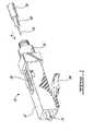
- FIG. 1is a perspective view of a reversible fiber connector with mechanical splice and sliding lock in accordance with an illustrative embodiment of the present invention
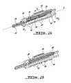
- FIG. 2Ais a sectional perspective view of the reversible fiber connector of FIG. 1 with the sliding lock in a released position in accordance with an illustrative embodiment of the present invention
- FIG. 2Bis a sectional perspective view of the reversible fiber connector of FIG. 1 with the sliding lock in a clamping position in accordance with an illustrative embodiment of the present invention
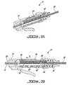
- FIG. 3Ais a sectional perspective view of the reversible fiber connector of FIG. 1 with the sliding lock in a released position during insertion of the fiber in accordance with an illustrative embodiment of the present invention
- FIG. 3Bis a front side view of the reversible fiber connector of FIG. 3A in accordance with an illustrative embodiment of the present invention
- FIG. 4Ais a sectional perspective view of the reversible fiber connector of FIG. 1 with the sliding lock in a released position and the fiber displaced to a final position, in accordance with an illustrative embodiment of the present invention
- FIG. 4Bis a front side view of the reversible fiber connector of FIG. 4A in accordance with an illustrative embodiment of the present invention
- FIG. 5Ais a sectional perspective view of the reversible fiber connector of FIG. 1 with the fiber displaced to a final position and the sliding lock moved to a clamping position in accordance with an illustrative embodiment of the present invention.
- FIG. 5Bis a front side view of the reversible fiber connector of FIG. 5A in accordance with an illustrative embodiment of the present invention.
- the connector 10is illustratively a re-terminable, no-crimp Local Connector (LC)-type optical connector that comprises a housing 12 having a front end, in which a ferrule 14 having affixed thereto an optical fiber stub (not shown) is received.
- the connector 10further comprises at a rear end thereof opposite the ferrule 14 a backbone 16 through which a mating optical fiber 18 is inserted into the connector 10 along the direction of arrow A for termination.
- LCLocal Connector
- the optical fiber 18is illustratively prepared for insertion into the connector 10 by removing a portion of the cable jacket 20 and coated or buffered portion 22 to expose a predetermined length of the bare glass fiber 18 .
- the connector 10further comprises a clamping mechanism comprising an actuator or sliding lock 24 , which when actuated ensures proper mating and alignment of the fiber stub 28 with the optical fiber 18 for accurate termination of the optical fiber 18 .
- a tab 26is further provided on a lower surface (not shown) of the connector 10 for insertion and retention thereof into an appropriately configured port of a patch panel or other device (both not shown) to permit signals to pass from the optical fiber 18 to the device and vice-versa.
- the connector housing(reference 12 in FIG. 1 ) is illustratively elongate and comprises a cavity (not shown) extending between the front and rear ends along a longitudinal axis X.
- An elongate ferrule holder 30is disposed in the housing cavity and surrounds one end of the ferrule 14 and associated fiber stub 28 .
- An alignment groove (V-shaped or “V-groove”) 32is illustratively provided on an inner surface of the ferrule holder 30 and extends between front and rear ends of the ferrule holder 30 along the longitudinal axis X.
- the groove 32has at each end thereof a funnel-shaped lead-in portion 34 1 , 34 2 , which provides a smooth transition for the fibers (reference 18 in FIG. 1) and 28 to be routed into the groove 32 from either end of the connector housing 12 , thus protecting the end face of the fibers 18 , 28 from damage.
- the first groove portion 34 1is illustratively positioned adjacent the ferrule 14 to facilitate the positioning and centering of the fiber stub 28 inside the ferrule 14 and of a protruding end (not shown) of the fiber stub 28 within the groove 32 .
- the ferrule 14illustratively comprises an axial bore (not shown), which is aligned with the groove 32 and in which the fiber stub 28 is disposed with the protruding end extending away from the front end of the housing 12 .
- the second groove portion 34 2is used to position the buffered portion 22 and accordingly center the fiber 18 within the connector housing 12 along the groove 32 so that an optical fiber splicing face (not shown) of the fiber 18 extends from the rear end of the housing 12 towards the front end to make physical contact with a stub splicing face (not shown) of the fiber stub 28 .
- index-matching gelmay be provided in the area of the groove 32 where the fibers 18 and 28 mate to refractively limit signal loss at the interface of the optical fiber 18 and the fiber stub 28 once the latter are properly aligned.
- a V-groove 32has been shown for illustrative purposes, the alignment groove 32 could have any other shape (e.g.
- the connector 10may be provided with a plurality of alignment grooves as in 32 to accommodate a dual-fiber or multi-fiber connector having two (2) or more fiber stubs as in 28 .
- the connector housing 12illustratively has mounted therein and extending towards the groove 32 a first mechanical splice anvil 36 used to maintain the fiber stub 28 and the optical fiber (reference 18 in FIG. 1 ) in alignment as well as a second mechanical splice anvil 38 positioned adjacent the first anvil 36 and used to exert pressure on the buffered portion 22 and on the bare fiber 18 , as will be discussed in further detail herein below.
- the anvils 36 and 38are positioned in abutment with an inner surface of the sliding lock 24 adjacent the groove 32 , with a clamping surface (not shown) of the anvil 36 overlapping the stub splicing face and the optical fiber splicing face of the adjoining fiber 18 and fiber stub 28 .
- the ferrule holder 30is further provided with a plurality of spaced projections or bosses as in 40 arranged along an outer surface thereof.
- the projections as in 40illustratively cooperate with apertures or holes as in 42 spaced by ribs 44 provided on an outer surface of the sliding lock 24 , thus behaving as a clamping mechanism suitable for urging the anvils as in 36 and 38 against the adjoining fiber stub 28 and optical fiber 18 , as will be discussed further herein below.
- the sliding lock 24is slideably mounted about the ferrule holder 30 and is displaceable along the longitudinal axis X (i.e. along directional arrow B) from a released position (illustrated in FIG.
- FIG. 2Ain which no pressure is applied on the anvils 36 and 38 and the fiber 18 can be freely inserted into the rear of the connector 10 along the groove 32 , to a clamping position (illustrated in FIG. 2B ), in which pressure is applied on both anvils 36 and 38 .
- the optical fiber 18is illustratively inserted into the connector 10 and guided along the groove 32 with the sliding lock 24 in the released position.
- the holes as in 42are in alignment with the projections as in 40 and accordingly each rib 44 is positioned in a corresponding slot (not shown) between a respective pair of projections as in 40 .
- roomis provided between the anvils 36 and 38 and the internal surface of the ferrule holder 30 for insertion of the fiber 18 into the connector 10 along the direction of arrow A ( FIG. 1 ).
- the fiber 18is advanced freely into the connector 10 until it reaches a final centered position (illustrated in FIG. 4A and FIG. 4B ), in which the optical fiber splicing face of the fiber 18 comes into physical contact with the adjoining stub splicing face of the fiber stub 28 .
- the sliding lock 24is moved to the clamping position, in which the projections as in 40 of the ferrule holder 30 are out of alignment with the holes as in 42 of the sliding lock 24 and each rib 44 of the sliding lock 24 is moved out of the corresponding slot (not shown) and positioned opposite a corresponding projection 40 for interference therewith.
- the inner surface of the sliding lock 24is moved in a direction perpendicular to the longitudinal axis (reference X in FIG. 2A ) and displaces both splice anvils 36 and 38 accordingly.
- a spring 46illustratively provides compressive resistance behind the ferrule 14 , thus ensuring adequate contact pressure between the ferrule 14 and a contact point on the port.
- the width of the slots (not shown) provided between the projections as in 40may either be substantially the same (as illustrated in FIG. 5A and FIG. 5B ) or set to vary along the length of the ferrule holder 30 such that when the sliding lock 24 is moved to the clamping position, the anvils 36 , 38 are not displaced at the same time.
- the slots between the projections as in 40 provided adjacent the anvil 36may have a smaller width than the slots provided adjacent the anvil 38 .
- the termination mechanism of the present inventionhas the advantage of being simple as well as nondestructively reusable. This is effected by returning the sliding lock 24 to the original released position (by sliding the lock 24 away from the ferrule 14 in a direction opposite to that of arrow B in FIG. 5B ), thus releasing clamping forces on both the optical fiber 18 and the fiber stub 28 .
- the optical fiber 18may then be withdrawn from the connector 10 (after having been terminated) and subsequently reinserted for another attempt at a successful connection in the event where optical continuity between the fibers 18 and 28 has been deemed unacceptable.
- the connector 10therefore eliminates the need for any extra and irreversible operation to crimp a lead-in tube or annular crimp ring about the buffered portion 22 of the fiber cable 20 and provide strain relief to the interface of the aligned field and fiber stubs 18 and 28 , as is the case of conventional connectors.
- crimpis destructive, such crimping typically degrades the fiber interface and such degraded connection cannot be improved short of cutting away the wasted connector, re-stripping and re-cleaving the optical fiber as in 18 , and re-terminating the optical fiber as in 18 with a new fiber stub as in 28 in a new connector.
- the assembly of the present inventionis advantageously adaptable to various types of fiber connectors, such as fiber connectors conformed to the Straight Tip (ST), Standard Connector (SC), or hybrid fiber and electrical contact standards.
- fiber connectorsconformed to the Straight Tip (ST), Standard Connector (SC), or hybrid fiber and electrical contact standards.
- STStraight Tip
- SCStandard Connector
- hybrid fiber and electrical contact standardssuch as fiber connectors conformed to the Straight Tip (ST), Standard Connector (SC), or hybrid fiber and electrical contact standards.
- STStraight Tip
- SCStandard Connector
Landscapes
- Physics & Mathematics (AREA)
- General Physics & Mathematics (AREA)
- Optics & Photonics (AREA)
- Mechanical Coupling Of Light Guides (AREA)
Abstract
Description
Claims (18)
Priority Applications (1)
| Application Number | Priority Date | Filing Date | Title |
|---|---|---|---|
| US12/484,614US7887244B2 (en) | 2008-06-13 | 2009-06-15 | Reversible fiber connector with mechanical splice and sliding lock |
Applications Claiming Priority (2)
| Application Number | Priority Date | Filing Date | Title |
|---|---|---|---|
| US6129508P | 2008-06-13 | 2008-06-13 | |
| US12/484,614US7887244B2 (en) | 2008-06-13 | 2009-06-15 | Reversible fiber connector with mechanical splice and sliding lock |
Publications (2)
| Publication Number | Publication Date |
|---|---|
| US20090310918A1 US20090310918A1 (en) | 2009-12-17 |
| US7887244B2true US7887244B2 (en) | 2011-02-15 |
Family
ID=41414878
Family Applications (1)
| Application Number | Title | Priority Date | Filing Date |
|---|---|---|---|
| US12/484,614Active2029-08-07US7887244B2 (en) | 2008-06-13 | 2009-06-15 | Reversible fiber connector with mechanical splice and sliding lock |
Country Status (1)
| Country | Link |
|---|---|
| US (1) | US7887244B2 (en) |
Cited By (3)
| Publication number | Priority date | Publication date | Assignee | Title |
|---|---|---|---|---|
| US20090317037A1 (en)* | 2008-06-23 | 2009-12-24 | Luc Milette | Reversible fiber connector with mechanical sliding splice |
| US9690065B2 (en) | 2014-09-12 | 2017-06-27 | Panduit Corp. | High density fiber enclosure and method |
| US10215944B2 (en) | 2016-06-30 | 2019-02-26 | Panduit Corp. | Modular fiber optic tray |
Families Citing this family (3)
| Publication number | Priority date | Publication date | Assignee | Title |
|---|---|---|---|---|
| US8596884B2 (en) | 2011-06-28 | 2013-12-03 | Corning Cable Systems Llc | Optical fiber mechanical splice connector systems and methods of coupling optical fibers |
| US10488597B2 (en) | 2015-10-12 | 2019-11-26 | Corning Research & Development Corporation | Connector for connecting two bare optical fibers |
| CN111258007B (en)* | 2020-03-26 | 2022-01-25 | 中航光电科技股份有限公司 | Optical fiber connector and tail wiring assembly thereof |
Citations (20)
| Publication number | Priority date | Publication date | Assignee | Title |
|---|---|---|---|---|
| US4435038A (en) | 1981-01-14 | 1984-03-06 | Amp Incorporated | Connector for use in butt splicing two optical fibres |
| US4669820A (en) | 1982-06-05 | 1987-06-02 | Amp Incorporated | Optical fiber termination method, terminal splice and connector therefor |
| US5138681A (en) | 1988-04-18 | 1992-08-11 | Minnesota Mining And Manufacturing Company | Optical fiber splice |
| US5341448A (en) | 1992-07-30 | 1994-08-23 | Advanced Custom Applications, Inc. | Optical fiber splice |
| US5394496A (en) | 1993-12-08 | 1995-02-28 | Northern Telecom Limited | Optical fiber mechanical splice |
| US5984532A (en) | 1995-08-24 | 1999-11-16 | Fujikura Ltd. | Optical fiber connector |
| US6179482B1 (en) | 1997-01-16 | 2001-01-30 | Fujikura, Ltd. | Optical connector and housing for optical connector |
| US6379054B2 (en) | 1998-07-01 | 2002-04-30 | Corning Cable Systems Llc | Field installable multifiber connector |
| US6604867B2 (en) | 2001-10-23 | 2003-08-12 | Panduit Corp. | Fiber optic connector |
| US7001084B2 (en) | 2003-12-30 | 2006-02-21 | 3M Innovative Properties Company | Fiber splice device |
| US7014372B2 (en) | 2001-10-04 | 2006-03-21 | Tyco Electronics Raychem Nv | Method and apparatus for splicing optical fibres |
| US20060153515A1 (en) | 2003-02-17 | 2006-07-13 | Toshihiko Honma | Optical fiber connecting tool |
| US7178990B2 (en) | 2003-08-25 | 2007-02-20 | Panduit Corp. | Reversible fiber optic stub fiber clamping mechanism |
| US20070127873A1 (en)* | 2004-06-30 | 2007-06-07 | Tyco Electronics Corporation | Optical fiber clamping assembly |
| US7241056B1 (en) | 2006-06-13 | 2007-07-10 | Panduit Corp. | Reversible fiber optic connector |
| US7258496B2 (en) | 2002-02-08 | 2007-08-21 | Fujikura Ltd. | Optical fiber connection tool and optical fiber connection method |
| US7264410B1 (en) | 2006-03-16 | 2007-09-04 | Corning Cable Systems Llc | Dual function splice component for mechanical splice connector |
| US7280733B2 (en) | 2005-10-24 | 2007-10-09 | 3M Innovative Properties Company | Fiber termination platform for optical connectors |
| US7346256B2 (en) | 2004-11-04 | 2008-03-18 | Panduit Corp. | Re-terminable LC connector assembly and cam termination tool |
| US20080075407A1 (en) | 2006-09-27 | 2008-03-27 | Fujikura Ltd. | Optical connector |
Family Cites Families (1)
| Publication number | Priority date | Publication date | Assignee | Title |
|---|---|---|---|---|
| WO2004112866A2 (en)* | 2003-06-17 | 2004-12-29 | Filtertek Inc. | Fluid handling device and method of making same |
- 2009
- 2009-06-15USUS12/484,614patent/US7887244B2/enactiveActive
Patent Citations (20)
| Publication number | Priority date | Publication date | Assignee | Title |
|---|---|---|---|---|
| US4435038A (en) | 1981-01-14 | 1984-03-06 | Amp Incorporated | Connector for use in butt splicing two optical fibres |
| US4669820A (en) | 1982-06-05 | 1987-06-02 | Amp Incorporated | Optical fiber termination method, terminal splice and connector therefor |
| US5138681A (en) | 1988-04-18 | 1992-08-11 | Minnesota Mining And Manufacturing Company | Optical fiber splice |
| US5341448A (en) | 1992-07-30 | 1994-08-23 | Advanced Custom Applications, Inc. | Optical fiber splice |
| US5394496A (en) | 1993-12-08 | 1995-02-28 | Northern Telecom Limited | Optical fiber mechanical splice |
| US5984532A (en) | 1995-08-24 | 1999-11-16 | Fujikura Ltd. | Optical fiber connector |
| US6179482B1 (en) | 1997-01-16 | 2001-01-30 | Fujikura, Ltd. | Optical connector and housing for optical connector |
| US6379054B2 (en) | 1998-07-01 | 2002-04-30 | Corning Cable Systems Llc | Field installable multifiber connector |
| US7014372B2 (en) | 2001-10-04 | 2006-03-21 | Tyco Electronics Raychem Nv | Method and apparatus for splicing optical fibres |
| US6604867B2 (en) | 2001-10-23 | 2003-08-12 | Panduit Corp. | Fiber optic connector |
| US7258496B2 (en) | 2002-02-08 | 2007-08-21 | Fujikura Ltd. | Optical fiber connection tool and optical fiber connection method |
| US20060153515A1 (en) | 2003-02-17 | 2006-07-13 | Toshihiko Honma | Optical fiber connecting tool |
| US7178990B2 (en) | 2003-08-25 | 2007-02-20 | Panduit Corp. | Reversible fiber optic stub fiber clamping mechanism |
| US7001084B2 (en) | 2003-12-30 | 2006-02-21 | 3M Innovative Properties Company | Fiber splice device |
| US20070127873A1 (en)* | 2004-06-30 | 2007-06-07 | Tyco Electronics Corporation | Optical fiber clamping assembly |
| US7346256B2 (en) | 2004-11-04 | 2008-03-18 | Panduit Corp. | Re-terminable LC connector assembly and cam termination tool |
| US7280733B2 (en) | 2005-10-24 | 2007-10-09 | 3M Innovative Properties Company | Fiber termination platform for optical connectors |
| US7264410B1 (en) | 2006-03-16 | 2007-09-04 | Corning Cable Systems Llc | Dual function splice component for mechanical splice connector |
| US7241056B1 (en) | 2006-06-13 | 2007-07-10 | Panduit Corp. | Reversible fiber optic connector |
| US20080075407A1 (en) | 2006-09-27 | 2008-03-27 | Fujikura Ltd. | Optical connector |
Cited By (17)
| Publication number | Priority date | Publication date | Assignee | Title |
|---|---|---|---|---|
| US8075198B2 (en)* | 2008-06-23 | 2011-12-13 | Belden Cdt (Canada) Inc. | Reversible fiber connector with mechanical sliding splice |
| US20090317037A1 (en)* | 2008-06-23 | 2009-12-24 | Luc Milette | Reversible fiber connector with mechanical sliding splice |
| US11624888B2 (en) | 2014-09-12 | 2023-04-11 | Panduit Corp. | High density fiber enclosure and method |
| US9690065B2 (en) | 2014-09-12 | 2017-06-27 | Panduit Corp. | High density fiber enclosure and method |
| US9864158B2 (en) | 2014-09-12 | 2018-01-09 | Panduit Corp. | High density fiber enclosure and method |
| US10268013B2 (en) | 2014-09-12 | 2019-04-23 | Panduit Corp. | High density fiber enclosure and method |
| US10317637B2 (en) | 2014-09-12 | 2019-06-11 | Panduit Corp. | High density fiber enclosure and method |
| US10606013B2 (en) | 2014-09-12 | 2020-03-31 | Panduit Corp. | High density fiber enclosure and method |
| US10698171B2 (en) | 2014-09-12 | 2020-06-30 | Panduit Corp. | High density fiber enclosure and method |
| US12228782B2 (en) | 2014-09-12 | 2025-02-18 | Panduit Corp. | High density fiber enclosure and method |
| US10768385B2 (en) | 2014-09-12 | 2020-09-08 | Panduit Corp. | High density fiber enclosure and method |
| US11105995B2 (en) | 2014-09-12 | 2021-08-31 | Panduit Corp. | High density fiber enclosure and method |
| US10215944B2 (en) | 2016-06-30 | 2019-02-26 | Panduit Corp. | Modular fiber optic tray |
| US11372185B2 (en) | 2016-06-30 | 2022-06-28 | Panduit Corp. | Modular fiber optic tray |
| US11709331B2 (en) | 2016-06-30 | 2023-07-25 | Panduit Corp. | Modular fiber optic tray |
| US12105338B2 (en) | 2016-06-30 | 2024-10-01 | Panduit Corp. | Modular fiber optic tray |
| US10725258B2 (en) | 2016-06-30 | 2020-07-28 | Panduit Corp. | Modular fiber optic tray |
Also Published As
| Publication number | Publication date |
|---|---|
| US20090310918A1 (en) | 2009-12-17 |
Similar Documents
| Publication | Publication Date | Title |
|---|---|---|
| US7811006B2 (en) | Field installable fiber optic connector and installation tool | |
| US11874510B2 (en) | Optical assembly with cable retainer | |
| US8801298B2 (en) | Slide actuated field installable fiber optic connector | |
| US7264410B1 (en) | Dual function splice component for mechanical splice connector | |
| US8075198B2 (en) | Reversible fiber connector with mechanical sliding splice | |
| US7887244B2 (en) | Reversible fiber connector with mechanical splice and sliding lock | |
| CN100406941C (en) | Fiber Optic Connectors and Connection Methods | |
| WO2005101076A1 (en) | Field-installable fusion splice fiber optic connector kit and method therefore | |
| EP2068183A1 (en) | Field-installable optical splice | |
| CN103364887B (en) | Optical-fiber connector | |
| CN103364883B (en) | Optical fiber connector | |
| JPH11218644A (en) | Optical fiber device and optical fiber subassembly | |
| US20090252458A1 (en) | Optical attenuator | |
| US20120301086A1 (en) | Tool-less clamping mechanism | |
| US5216736A (en) | Welded splice element | |
| JP7201276B2 (en) | Field-assembled optical connectors that prevent optical fiber bending | |
| US20190278025A1 (en) | Connector loader | |
| US5235664A (en) | Apparatus for inserting optical cable into ferrule | |
| US12326594B2 (en) | Optical connector and method of manufacturing optical connector | |
| CN205067803U (en) | Mutual connecting device of light | |
| WO2013150089A1 (en) | Mechanical alignment device for positioning optical fibers | |
| JP3004234B2 (en) | Optical fiber connection method and connector | |
| CN113835162A (en) | Splicing core and optical fiber quick connector thereof | |
| JP2005121733A (en) | Optical fiber connecting member and optical fiber connecting method |
Legal Events
| Date | Code | Title | Description |
|---|---|---|---|
| AS | Assignment | Owner name:BELDEN CDT (CANADA) INC., CANADA Free format text:NUNC PRO TUNC ASSIGNMENT;ASSIGNORS:MILETTE, LUC;LEVY, MOISE;SIGNING DATES FROM 20090730 TO 20090731;REEL/FRAME:023157/0962 | |
| FEPP | Fee payment procedure | Free format text:PAYOR NUMBER ASSIGNED (ORIGINAL EVENT CODE: ASPN); ENTITY STATUS OF PATENT OWNER: LARGE ENTITY | |
| STCF | Information on status: patent grant | Free format text:PATENTED CASE | |
| FPAY | Fee payment | Year of fee payment:4 | |
| MAFP | Maintenance fee payment | Free format text:PAYMENT OF MAINTENANCE FEE, 8TH YEAR, LARGE ENTITY (ORIGINAL EVENT CODE: M1552) Year of fee payment:8 | |
| AS | Assignment | Owner name:BELDEN CANADA INC., CANADA Free format text:MERGER AND CHANGE OF NAME;ASSIGNORS:BELDEN CDT (CANADA) INC.;MIRANDA TECHNOLOGIES ULC;BYRES SECURITY ULC;AND OTHERS;REEL/FRAME:054550/0751 Effective date:20121101 Owner name:BELDEN CANADA ULC, CANADA Free format text:ASSIGNMENT OF ASSIGNORS INTEREST;ASSIGNOR:BELDEN CANADA INC.;REEL/FRAME:054592/0263 Effective date:20200320 | |
| MAFP | Maintenance fee payment | Free format text:PAYMENT OF MAINTENANCE FEE, 12TH YEAR, LARGE ENTITY (ORIGINAL EVENT CODE: M1553); ENTITY STATUS OF PATENT OWNER: LARGE ENTITY Year of fee payment:12 |