US7886989B2 - Liquid material dispensing apparatus and method utilizing pulsed pressurized air - Google Patents
Liquid material dispensing apparatus and method utilizing pulsed pressurized airDownload PDFInfo
- Publication number
- US7886989B2 US7886989B2US10/700,612US70061203AUS7886989B2US 7886989 B2US7886989 B2US 7886989B2US 70061203 AUS70061203 AUS 70061203AUS 7886989 B2US7886989 B2US 7886989B2
- Authority
- US
- United States
- Prior art keywords
- air
- liquid material
- liquid
- dispensing
- outlet
- Prior art date
- Legal status (The legal status is an assumption and is not a legal conclusion. Google has not performed a legal analysis and makes no representation as to the accuracy of the status listed.)
- Expired - Fee Related, expires
Links
Images


Classifications
- B—PERFORMING OPERATIONS; TRANSPORTING
- B05—SPRAYING OR ATOMISING IN GENERAL; APPLYING FLUENT MATERIALS TO SURFACES, IN GENERAL
- B05C—APPARATUS FOR APPLYING FLUENT MATERIALS TO SURFACES, IN GENERAL
- B05C5/00—Apparatus in which liquid or other fluent material is projected, poured or allowed to flow on to the surface of the work
- B05C5/02—Apparatus in which liquid or other fluent material is projected, poured or allowed to flow on to the surface of the work the liquid or other fluent material being discharged through an outlet orifice by pressure, e.g. from an outlet device in contact or almost in contact, with the work
- B05C5/027—Coating heads with several outlets, e.g. aligned transversally to the moving direction of a web to be coated
- B—PERFORMING OPERATIONS; TRANSPORTING
- B05—SPRAYING OR ATOMISING IN GENERAL; APPLYING FLUENT MATERIALS TO SURFACES, IN GENERAL
- B05B—SPRAYING APPARATUS; ATOMISING APPARATUS; NOZZLES
- B05B7/00—Spraying apparatus for discharge of liquids or other fluent materials from two or more sources, e.g. of liquid and air, of powder and gas
- B05B7/02—Spray pistols; Apparatus for discharge
- B05B7/08—Spray pistols; Apparatus for discharge with separate outlet orifices, e.g. to form parallel jets, i.e. the axis of the jets being parallel, to form intersecting jets, i.e. the axis of the jets converging but not necessarily intersecting at a point
- B05B7/0807—Spray pistols; Apparatus for discharge with separate outlet orifices, e.g. to form parallel jets, i.e. the axis of the jets being parallel, to form intersecting jets, i.e. the axis of the jets converging but not necessarily intersecting at a point to form intersecting jets
- B05B7/0815—Spray pistols; Apparatus for discharge with separate outlet orifices, e.g. to form parallel jets, i.e. the axis of the jets being parallel, to form intersecting jets, i.e. the axis of the jets converging but not necessarily intersecting at a point to form intersecting jets with at least one gas jet intersecting a jet constituted by a liquid or a mixture containing a liquid for controlling the shape of the latter
- B—PERFORMING OPERATIONS; TRANSPORTING
- B05—SPRAYING OR ATOMISING IN GENERAL; APPLYING FLUENT MATERIALS TO SURFACES, IN GENERAL
- B05C—APPARATUS FOR APPLYING FLUENT MATERIALS TO SURFACES, IN GENERAL
- B05C5/00—Apparatus in which liquid or other fluent material is projected, poured or allowed to flow on to the surface of the work
- B05C5/001—Apparatus in which liquid or other fluent material is projected, poured or allowed to flow on to the surface of the work incorporating means for heating or cooling the liquid or other fluent material
Definitions
- the present inventionrelates generally to material dispensing systems for applying liquid material onto a moving substrate, and more particularly to a material dispensing system utilizing pressurized air to control the pattern of material dispensed to a moving substrate.
- hot melt adhesive dispensing systemshave been developed for applying a laminating or bonding layer of hot melt thermoplastic adhesive between a non-woven fibrous layer and a thin polyethylene backsheet.
- the hot melt adhesive dispensing systemis mounted above a moving polyethylene backsheet layer and applies a uniform pattern of hot melt adhesive material across the width of the backsheet substrate.
- a non-woven layeris laminated to the polyethylene layer through a pressure nip and then further processed into a final product.
- continuous beads or filaments of adhesiveare emitted from a multiple adhesive outlet die with multiple air jets oriented around the circumference of each material outlet.
- the multiple air jetsare tangentially directed relative to the orientation of the adhesive filament as it emits from the die orifice, thereby attenuating each adhesive filament and causing the filaments to swirl before being deposited on the upper surface of the moving substrate.
- hot melt adhesive dispensing systemshave incorporated slot nozzle dies with a pair of angled air channels formed on either side of the elongated extrusion slot of the die.
- pressurized airis emitted as a pair of curtains from the air channels to impinge upon, attenuate and fiberize the adhesive curtain to form a uniform fibrous web of adhesive on the substrate.
- fibrous web adhesive dispensershave incorporated intermittent control of adhesive and air flows to form discrete patterns of fibrous adhesive layers with well defined cut-on and cut-off edges and well defined side edges.
- Meltblown technologyhas also been adapted for use in this area to produce a hot melt adhesive bonding layer having fibers of relatively small diameter.
- Meltblown diestypically include a series of closely spaced orifices in one or more dies or nozzles that are aligned on a common axis across the die head. An angled air channel is provided on each side of the orifices. As hot melt adhesive emits from the series of aligned nozzles, pressurized air is emitted from the air channels as a pair of curtains that impinge upon, draw down and attenuate the fibers before they are applied to the moving substrate.
- the present inventionprovides a dispensing system in which pressurized air is varied to control the movement of a liquid material stream dispensed from a liquid discharge outlet.
- the systemcomprises a dispensing module coupled to a supply of liquid material and a source of pressurized air.
- a nozzle or die coupled to the modulereceives liquid material and pressurized air though the module and dispenses the liquid material through a liquid discharge outlet.
- An air outlet proximate the liquid discharge outletdirects the pressurized air toward the dispensed liquid material to attenuate and deflect the liquid material.
- the pressure of the airis varied as the liquid discharge is maintained to cause the liquid material to move in a desired pattern as it is dispensed from the liquid discharge outlet.
- the dispensing systemfurther comprises a valve coupled to the nozzle and operable to vary the pressurized air discharged from the air outlet.
- the valveis operable to rapidly pulse the air to thereby move the liquid material in a desired generally oscillating pattern. More specifically, the valve can pulse the air at a rate of approximately 500 to 2000 cycles per second.
- the valvemay be operated between open and closed positions to vary the pressure of the air. Alternatively, it may be operated to and between the open position, the closed position, and at least one position intermediate the open and closed positions, whereby the air may be pulsed by the valve to vary the pressure above and below an intermediate pressure.
- the nozzlehas first and second liquid discharge outlets for dispensing liquid material therefrom.
- An air outletis positioned between the first and second liquid discharge outlets. Pressurized air discharges from the air outlet toward the liquid material dispensed from both liquid discharge outlets.
- the valveis operable to vary the pressurized air from the air outlet, whereby both streams of liquid material may be moved by the pressurized air to create desired patterns of liquid material on a substrate.
- a method according to this inventioncan include dispensing liquid material from a liquid discharge outlet, directing a stream of pressurized air toward the dispensed liquid material, and varying the pressure of the pressurized air while discharging the liquid material to thereby move the dispensed liquid material in a desired pattern.
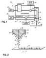
- FIG. 1is a schematic illustration of a liquid dispensing system according to the present invention
- FIG. 2is a is an enlarged view of system of FIG. 1 , depicting liquid material being dispensed to a substrate according to the present invention
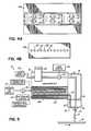
- FIG. 3Ais a perspective view of an exemplary dispensing module, according to the present invention.
- FIG. 3Bis a perspective view of another exemplary dispensing module according to the present invention.
- FIG. 4Ais a bottom view of an exemplary nozzle used on the exemplary module of FIG. 3A ;
- FIG. 4Bis a bottom view of an exemplary nozzle used on the exemplary module of FIG. 3B ;
- FIG. 5is a schematic illustration depicting another exemplary embodiment of a liquid dispensing system according to the present invention.
- the system 10includes a dispensing module 16 coupled to a liquid material manifold 18 and a process air manifold 20 for receiving liquid material and process air from a liquid material supply 22 and a process air supply 24 .
- the liquid material manifold 18may be provided with a filter 26 for filtering out contaminates or other unwanted debris from the liquid.
- the liquid manifold 18 and air manifold 20may also be heated, as known in the art, to maintain the liquid material 12 and process air at desired temperatures, and to maintain the liquid material 12 at a desired viscosity until dispensed onto the substrate 14 .
- the dispensing system 10further includes a controllable valve 28 disposed between the liquid material supply 22 and the dispensing module 16 to control the flow of liquid material 12 as desired.
- the dispensing system 10further includes an air valve 30 disposed between the process air supply 24 and the dispensing module 16 for controlling the pressurized air provided to the module 16 .
- the dispensing module 16is couplable to the liquid manifold 18 and the air manifold 20 , and has a liquid supply passage 40 in communication with the liquid supply 22 , and an air supply passage 42 in communication with the process air supply 24 .
- the dispensing module 16is configured to receive and support a nozzle 44 for dispensing the liquid material 12 therefrom. Accordingly, the nozzle 44 includes a liquid discharge passage 46 in fluid communication with the liquid supply passage 40 of the dispensing module 16 , and an air discharge passage 48 in fluid communication with the air supply passage 42 of the module 16 .
- the nozzle 44further includes a liquid discharge outlet 50 for dispensing the liquid material 12 to the substrate 14 .
- the air discharge passage 48has an air outlet 52 proximate the liquid discharge outlet 50 whereby the air discharged from the air outlet 52 is directed toward the liquid material 12 dispensed from the liquid discharge outlet 50 , as depicted most clearly in FIG. 2 .
- FIG. 3Adepicts an exemplary module 16 a which receives a nozzle 44 a coupled to a bottom surface of the module 16 a .
- module 16 bdepicts another exemplary module 16 b configured to receive a nozzle 44 b coupled to a side surface of the module 16 b . It will be recognized, however, that module 16 and nozzle 44 may have other configurations for dispensing liquid material 12 to a substrate 14 , as known in the art.
- liquid discharge outlet 50 and air outlet 52 of nozzle 44may be provided in a variety of arrangements and configurations to produce various desired patterns of dispensed liquid material 12 , such as oscillating patterns or swirl patterns, as known in the art.
- a nozzle 44may have a single liquid discharge outlet 50 and a single air outlet 52 , or one or more liquid discharge outlets 50 may be associated with one or more air outlets 52 to create the desired pattern of dispensed liquid material 12 .
- FIG. 4Adepicts an exemplary nozzle 44 a wherein each of a plurality of liquid discharge outlets 50 is associated with multiple air outlets 52 .
- pressurized air discharged from the multiple air outlets 52 associated with each liquid discharge outlet 50attenuates and deflects the liquid material 12 dispensed from the liquid discharge outlet 50 to create a desired pattern on substrate 14 .
- FIG. 4Bdepicts another embodiment wherein a plurality of liquid discharge outlets 50 and air outlets 52 are arranged in a linear fashion with each air outlet 52 associated with two liquid discharge outlets 50 , one on either side of the air outlets 52 .
- pressurized air from each air outlet 52attenuates and deflects liquid material 12 dispensed from each of the liquid discharge outlets 50 disposed on opposite sides of the air outlet 52 .
- the air valve 30is used to vary the air pressure by as much as about 30 psi. In yet another embodiment, the air valve 30 is configured to pulse the air at a rate of approximately 500 cycles per second to approximately 2000 cycles per second.
- the liquid discharge outlets 50 and air outlets 52have diameters in the range of about 0.008′′ to about 0.030′′.
- the flow rate of the liquidcan be about 10 grams/min./stream at a viscosity of between about 1,000 cps to about 10,000 cps.
- the aircan be set to a pressure between about 5 psi to about 15 psi at a flow rate of about 0.1 cfm to about 2.0 cfm.
- the air valve 30is a solenoid valve and is actuated by a controller 60 configured to operate the valve 30 such that a desired pressure is provided to the dispensed liquid material 12 at a desired pulse frequency to thereby create a desired pattern on the moving substrate 14 .
- the controller 60 for the air valve 30may be independent or may be combined with a control unit 62 which actuates the liquid valve 28 .
- the air valve 30is positioned within the air manifold 20 , adjacent to the nozzle 44 , to minimize the distance between the air valve 30 and the nozzle 44 such that more robust control of the pulsed air may be maintained.
- the air valve 30may be provided between the process air supply 24 and the air manifold 20 , as shown in the embodiment of FIG. 5 , wherein components similar to those described above have been similarly numbered.
- the air manifold 20 acomprises a flat plate heater, such as that described in U.S. patent application Ser. No. 10/282,573, assigned to the assignee of the present invention.
- the small dimensions of the air passage 64 in the flat plate heaterallow robust control of the pulsed air provided to the nozzle 44 .
- a method of dispensing liquid material 12 to a substrate 14comprises dispensing the liquid material 12 from a liquid discharge outlet 50 , directing a stream of pressurized air toward the dispensed liquid material 12 , and varying the pressure of the pressurized air to create a desired pattern of dispensed liquid material 12 .
- varying the pressure of the pressurized aircomprises pulsing the pressurized air.
- pulsing the pressurized aircomprises pulsing the air between approximately 500 and 2000 cycles per second.
Landscapes
- Coating Apparatus (AREA)
- Application Of Or Painting With Fluid Materials (AREA)
Abstract
Description
Claims (12)
Priority Applications (1)
| Application Number | Priority Date | Filing Date | Title |
|---|---|---|---|
| US10/700,612US7886989B2 (en) | 2003-11-04 | 2003-11-04 | Liquid material dispensing apparatus and method utilizing pulsed pressurized air |
Applications Claiming Priority (1)
| Application Number | Priority Date | Filing Date | Title |
|---|---|---|---|
| US10/700,612US7886989B2 (en) | 2003-11-04 | 2003-11-04 | Liquid material dispensing apparatus and method utilizing pulsed pressurized air |
Publications (2)
| Publication Number | Publication Date |
|---|---|
| US20050092775A1 US20050092775A1 (en) | 2005-05-05 |
| US7886989B2true US7886989B2 (en) | 2011-02-15 |
Family
ID=34551246
Family Applications (1)
| Application Number | Title | Priority Date | Filing Date |
|---|---|---|---|
| US10/700,612Expired - Fee RelatedUS7886989B2 (en) | 2003-11-04 | 2003-11-04 | Liquid material dispensing apparatus and method utilizing pulsed pressurized air |
Country Status (1)
| Country | Link |
|---|---|
| US (1) | US7886989B2 (en) |
Cited By (5)
| Publication number | Priority date | Publication date | Assignee | Title |
|---|---|---|---|---|
| CN103372521A (en)* | 2012-04-20 | 2013-10-30 | Tdk株式会社 | Application head and droplet applying apparatus |
| US9533316B2 (en)* | 2015-03-31 | 2017-01-03 | Stolle Machinery Company, Llc | Spray gun with air halo nozzle assembly |
| IT201800009720A1 (en)* | 2018-10-23 | 2020-04-23 | Isopan Spa | DEVICE FOR DISPENSING A LIQUID |
| US20220048062A1 (en)* | 2019-04-05 | 2022-02-17 | Nordson Corporation | Applicator air manifold |
| US20240066533A1 (en)* | 2022-08-30 | 2024-02-29 | Full Power Idea Tech Ltd. | Inner Spiral Nozzle |
Families Citing this family (10)
| Publication number | Priority date | Publication date | Assignee | Title |
|---|---|---|---|---|
| US7617951B2 (en) | 2002-01-28 | 2009-11-17 | Nordson Corporation | Compact heated air manifolds for adhesive application |
| US20050242108A1 (en) | 2004-04-30 | 2005-11-03 | Nordson Corporation | Liquid dispenser having individualized process air control |
| US20060175432A1 (en)* | 2005-01-21 | 2006-08-10 | Reuben Brock | Apparatus and method for applying controlled patterns of liquid |
| CN101356014B (en)* | 2006-01-06 | 2013-04-24 | 诺信公司 | Liquid distributors with individual process air controls |
| US20100224123A1 (en)* | 2009-03-09 | 2010-09-09 | Illinois Tool Works Inc. | Modular nozzle unit for web moistening |
| US9186881B2 (en) | 2009-03-09 | 2015-11-17 | Illinois Tool Works Inc. | Thermally isolated liquid supply for web moistening |
| DE102009034687B4 (en)* | 2009-07-24 | 2017-03-30 | Windmöller & Hölscher Kg | Device and method for providing workpieces or webs with glue |
| CN102773180A (en)* | 2012-08-10 | 2012-11-14 | 福建省精泰设备制造有限公司 | Sizing nozzle |
| CN103824754A (en)* | 2014-03-15 | 2014-05-28 | 深圳市鹰眼在线电子科技有限公司 | Intelligent laminating machine for quartz crystal oscillator |
| JP7574244B2 (en)* | 2022-06-23 | 2024-10-28 | 株式会社モリタ製作所 | Dental Handpieces |
Citations (11)
| Publication number | Priority date | Publication date | Assignee | Title |
|---|---|---|---|---|
| US4957783A (en)* | 1988-10-05 | 1990-09-18 | Nordson Corporation | Method and apparatus for dispensing droplets of molten thermoplastic adhesive |
| US4995333A (en)* | 1989-09-15 | 1991-02-26 | Kimberly-Clark Corporation | Sprayed adhesive system for applying a continuous filament of theroplastic material and imparting a swirling motion thereto |
| US5322706A (en)* | 1990-10-19 | 1994-06-21 | Merkel Stephen L | Method of monitoring parameters of coating material dispensing systems and processes by analysis of swirl pattern dynamics |
| US5540804A (en) | 1992-04-08 | 1996-07-30 | Nordson Corporation | Dual format adhesive apparatus, process and article |
| US5740963A (en)* | 1997-01-07 | 1998-04-21 | Nordson Corporation | Self-sealing slot nozzle die |
| US5800867A (en)* | 1992-08-13 | 1998-09-01 | Nordson Corporation | Deflection control of liquid or powder stream during dispensing |
| WO1999054057A1 (en)* | 1998-04-17 | 1999-10-28 | Nordson Corporation | Method and apparatus for applying a controlled pattern of fibrous material to a moving substrate |
| US6325853B1 (en)* | 1996-07-19 | 2001-12-04 | Nordson Corporation | Apparatus for applying a liquid coating with an improved spray nozzle |
| US6814310B2 (en)* | 2002-11-26 | 2004-11-09 | Nordson Corporation | Metered liquid dispensing system |
| US6911232B2 (en)* | 2002-04-12 | 2005-06-28 | Nordson Corporation | Module, nozzle and method for dispensing controlled patterns of liquid material |
| US7617951B2 (en)* | 2002-01-28 | 2009-11-17 | Nordson Corporation | Compact heated air manifolds for adhesive application |
- 2003
- 2003-11-04USUS10/700,612patent/US7886989B2/ennot_activeExpired - Fee Related
Patent Citations (11)
| Publication number | Priority date | Publication date | Assignee | Title |
|---|---|---|---|---|
| US4957783A (en)* | 1988-10-05 | 1990-09-18 | Nordson Corporation | Method and apparatus for dispensing droplets of molten thermoplastic adhesive |
| US4995333A (en)* | 1989-09-15 | 1991-02-26 | Kimberly-Clark Corporation | Sprayed adhesive system for applying a continuous filament of theroplastic material and imparting a swirling motion thereto |
| US5322706A (en)* | 1990-10-19 | 1994-06-21 | Merkel Stephen L | Method of monitoring parameters of coating material dispensing systems and processes by analysis of swirl pattern dynamics |
| US5540804A (en) | 1992-04-08 | 1996-07-30 | Nordson Corporation | Dual format adhesive apparatus, process and article |
| US5800867A (en)* | 1992-08-13 | 1998-09-01 | Nordson Corporation | Deflection control of liquid or powder stream during dispensing |
| US6325853B1 (en)* | 1996-07-19 | 2001-12-04 | Nordson Corporation | Apparatus for applying a liquid coating with an improved spray nozzle |
| US5740963A (en)* | 1997-01-07 | 1998-04-21 | Nordson Corporation | Self-sealing slot nozzle die |
| WO1999054057A1 (en)* | 1998-04-17 | 1999-10-28 | Nordson Corporation | Method and apparatus for applying a controlled pattern of fibrous material to a moving substrate |
| US7617951B2 (en)* | 2002-01-28 | 2009-11-17 | Nordson Corporation | Compact heated air manifolds for adhesive application |
| US6911232B2 (en)* | 2002-04-12 | 2005-06-28 | Nordson Corporation | Module, nozzle and method for dispensing controlled patterns of liquid material |
| US6814310B2 (en)* | 2002-11-26 | 2004-11-09 | Nordson Corporation | Metered liquid dispensing system |
Non-Patent Citations (1)
| Title |
|---|
| Rajiv S. Rao et al. Vibration and Stability in the Melt Blowing Process, Ind. Eng. Chem., 32 pgs., 3100-3111, 1993. |
Cited By (7)
| Publication number | Priority date | Publication date | Assignee | Title |
|---|---|---|---|---|
| CN103372521A (en)* | 2012-04-20 | 2013-10-30 | Tdk株式会社 | Application head and droplet applying apparatus |
| CN103372521B (en)* | 2012-04-20 | 2016-09-21 | Tdk株式会社 | Coating head and apparatus for coating liquid droplet |
| US9533316B2 (en)* | 2015-03-31 | 2017-01-03 | Stolle Machinery Company, Llc | Spray gun with air halo nozzle assembly |
| IT201800009720A1 (en)* | 2018-10-23 | 2020-04-23 | Isopan Spa | DEVICE FOR DISPENSING A LIQUID |
| US20220048062A1 (en)* | 2019-04-05 | 2022-02-17 | Nordson Corporation | Applicator air manifold |
| US12138653B2 (en)* | 2019-04-05 | 2024-11-12 | Nordson Corporation | Applicator air manifold |
| US20240066533A1 (en)* | 2022-08-30 | 2024-02-29 | Full Power Idea Tech Ltd. | Inner Spiral Nozzle |
Also Published As
| Publication number | Publication date |
|---|---|
| US20050092775A1 (en) | 2005-05-05 |
Similar Documents
| Publication | Publication Date | Title |
|---|---|---|
| US7886989B2 (en) | Liquid material dispensing apparatus and method utilizing pulsed pressurized air | |
| EP0417815B2 (en) | Method and apparatus for applying a selected pattern of work material on a substrate | |
| US6378782B1 (en) | Method and apparatus for applying a controlled pattern of fibrous material to a moving substrate | |
| AU727472B2 (en) | Omega spray pattern and method therefor | |
| EP0346928B1 (en) | Absorbent article, method and apparatus for making same | |
| EP1932598B9 (en) | Multi-plate nozzle and method for dispensing random pattern of adhesive filaments | |
| US4891249A (en) | Method of and apparatus for somewhat-to-highly viscous fluid spraying for fiber or filament generation, controlled droplet generation, and combinations of fiber and droplet generation, intermittent and continuous, and for air-controlling spray deposition | |
| EP0835952B1 (en) | Meltblowing method and apparatus | |
| US5124111A (en) | Method of forming a substantially continous swirled filament | |
| USRE39399E1 (en) | Segmented die for applying hot melt adhesives or other polymer melts | |
| US5316836A (en) | Sprayed adhesive diaper construction | |
| JPH06170308A (en) | Device and method for applying discrete coating | |
| US20060251806A1 (en) | Method of securing elastic strands to flat substrates and apparatus therefor | |
| JP5062963B2 (en) | Inclined manifold and discharge device | |
| JP4402894B2 (en) | Apparatus and method for dispensing adhesive on a strand | |
| JP2025511213A (en) | Full coverage/fine line spray coating method |
Legal Events
| Date | Code | Title | Description |
|---|---|---|---|
| AS | Assignment | Owner name:NORDSON CORPORATION, OHIO Free format text:ASSIGNMENT OF ASSIGNORS INTEREST;ASSIGNORS:SAIDMAN, LAURENCE B.;BROCK, REUBEN F.;REEL/FRAME:015023/0082;SIGNING DATES FROM 20031103 TO 20031112 Owner name:NORDSON CORPORATION, OHIO Free format text:ASSIGNMENT OF ASSIGNORS INTEREST;ASSIGNORS:SAIDMAN, LAURENCE B.;BROCK, REUBEN F.;SIGNING DATES FROM 20031103 TO 20031112;REEL/FRAME:015023/0082 | |
| FEPP | Fee payment procedure | Free format text:PAYOR NUMBER ASSIGNED (ORIGINAL EVENT CODE: ASPN); ENTITY STATUS OF PATENT OWNER: LARGE ENTITY | |
| FEPP | Fee payment procedure | Free format text:PAYER NUMBER DE-ASSIGNED (ORIGINAL EVENT CODE: RMPN); ENTITY STATUS OF PATENT OWNER: LARGE ENTITY Free format text:PAYOR NUMBER ASSIGNED (ORIGINAL EVENT CODE: ASPN); ENTITY STATUS OF PATENT OWNER: LARGE ENTITY | |
| STCF | Information on status: patent grant | Free format text:PATENTED CASE | |
| FPAY | Fee payment | Year of fee payment:4 | |
| MAFP | Maintenance fee payment | Free format text:PAYMENT OF MAINTENANCE FEE, 8TH YEAR, LARGE ENTITY (ORIGINAL EVENT CODE: M1552) Year of fee payment:8 | |
| FEPP | Fee payment procedure | Free format text:MAINTENANCE FEE REMINDER MAILED (ORIGINAL EVENT CODE: REM.); ENTITY STATUS OF PATENT OWNER: LARGE ENTITY | |
| LAPS | Lapse for failure to pay maintenance fees | Free format text:PATENT EXPIRED FOR FAILURE TO PAY MAINTENANCE FEES (ORIGINAL EVENT CODE: EXP.); ENTITY STATUS OF PATENT OWNER: LARGE ENTITY | |
| STCH | Information on status: patent discontinuation | Free format text:PATENT EXPIRED DUE TO NONPAYMENT OF MAINTENANCE FEES UNDER 37 CFR 1.362 | |
| FP | Lapsed due to failure to pay maintenance fee | Effective date:20230215 |