US7886739B2 - System and method for circuit compliance compensated volume control in a patient respiratory ventilator - Google Patents
System and method for circuit compliance compensated volume control in a patient respiratory ventilatorDownload PDFInfo
- Publication number
- US7886739B2 US7886739B2US11/247,568US24756805AUS7886739B2US 7886739 B2US7886739 B2US 7886739B2US 24756805 AUS24756805 AUS 24756805AUS 7886739 B2US7886739 B2US 7886739B2
- Authority
- US
- United States
- Prior art keywords
- volume
- vol
- net
- tid
- circuit
- Prior art date
- Legal status (The legal status is an assumption and is not a legal conclusion. Google has not performed a legal analysis and makes no representation as to the accuracy of the status listed.)
- Active, expires
Links
Images


Classifications
- A—HUMAN NECESSITIES
- A61—MEDICAL OR VETERINARY SCIENCE; HYGIENE
- A61M—DEVICES FOR INTRODUCING MEDIA INTO, OR ONTO, THE BODY; DEVICES FOR TRANSDUCING BODY MEDIA OR FOR TAKING MEDIA FROM THE BODY; DEVICES FOR PRODUCING OR ENDING SLEEP OR STUPOR
- A61M16/00—Devices for influencing the respiratory system of patients by gas treatment, e.g. ventilators; Tracheal tubes
- A61M16/0051—Devices for influencing the respiratory system of patients by gas treatment, e.g. ventilators; Tracheal tubes with alarm devices
- A—HUMAN NECESSITIES
- A61—MEDICAL OR VETERINARY SCIENCE; HYGIENE
- A61M—DEVICES FOR INTRODUCING MEDIA INTO, OR ONTO, THE BODY; DEVICES FOR TRANSDUCING BODY MEDIA OR FOR TAKING MEDIA FROM THE BODY; DEVICES FOR PRODUCING OR ENDING SLEEP OR STUPOR
- A61M16/00—Devices for influencing the respiratory system of patients by gas treatment, e.g. ventilators; Tracheal tubes
- A61M16/021—Devices for influencing the respiratory system of patients by gas treatment, e.g. ventilators; Tracheal tubes operated by electrical means
- A61M16/022—Control means therefor
- A61M16/024—Control means therefor including calculation means, e.g. using a processor
- A61M16/026—Control means therefor including calculation means, e.g. using a processor specially adapted for predicting, e.g. for determining an information representative of a flow limitation during a ventilation cycle by using a root square technique or a regression analysis
- A—HUMAN NECESSITIES
- A61—MEDICAL OR VETERINARY SCIENCE; HYGIENE
- A61M—DEVICES FOR INTRODUCING MEDIA INTO, OR ONTO, THE BODY; DEVICES FOR TRANSDUCING BODY MEDIA OR FOR TAKING MEDIA FROM THE BODY; DEVICES FOR PRODUCING OR ENDING SLEEP OR STUPOR
- A61M16/00—Devices for influencing the respiratory system of patients by gas treatment, e.g. ventilators; Tracheal tubes
- A61M16/0003—Accessories therefor, e.g. sensors, vibrators, negative pressure
- A61M2016/0015—Accessories therefor, e.g. sensors, vibrators, negative pressure inhalation detectors
- A61M2016/0018—Accessories therefor, e.g. sensors, vibrators, negative pressure inhalation detectors electrical
- A61M2016/0021—Accessories therefor, e.g. sensors, vibrators, negative pressure inhalation detectors electrical with a proportional output signal, e.g. from a thermistor
- A—HUMAN NECESSITIES
- A61—MEDICAL OR VETERINARY SCIENCE; HYGIENE
- A61M—DEVICES FOR INTRODUCING MEDIA INTO, OR ONTO, THE BODY; DEVICES FOR TRANSDUCING BODY MEDIA OR FOR TAKING MEDIA FROM THE BODY; DEVICES FOR PRODUCING OR ENDING SLEEP OR STUPOR
- A61M16/00—Devices for influencing the respiratory system of patients by gas treatment, e.g. ventilators; Tracheal tubes
- A61M16/0003—Accessories therefor, e.g. sensors, vibrators, negative pressure
- A61M2016/003—Accessories therefor, e.g. sensors, vibrators, negative pressure with a flowmeter
- A61M2016/0033—Accessories therefor, e.g. sensors, vibrators, negative pressure with a flowmeter electrical
- A61M2016/0039—Accessories therefor, e.g. sensors, vibrators, negative pressure with a flowmeter electrical in the inspiratory circuit
- A—HUMAN NECESSITIES
- A61—MEDICAL OR VETERINARY SCIENCE; HYGIENE
- A61M—DEVICES FOR INTRODUCING MEDIA INTO, OR ONTO, THE BODY; DEVICES FOR TRANSDUCING BODY MEDIA OR FOR TAKING MEDIA FROM THE BODY; DEVICES FOR PRODUCING OR ENDING SLEEP OR STUPOR
- A61M16/00—Devices for influencing the respiratory system of patients by gas treatment, e.g. ventilators; Tracheal tubes
- A61M16/0003—Accessories therefor, e.g. sensors, vibrators, negative pressure
- A61M2016/003—Accessories therefor, e.g. sensors, vibrators, negative pressure with a flowmeter
- A61M2016/0033—Accessories therefor, e.g. sensors, vibrators, negative pressure with a flowmeter electrical
- A61M2016/0042—Accessories therefor, e.g. sensors, vibrators, negative pressure with a flowmeter electrical in the expiratory circuit
- A—HUMAN NECESSITIES
- A61—MEDICAL OR VETERINARY SCIENCE; HYGIENE
- A61M—DEVICES FOR INTRODUCING MEDIA INTO, OR ONTO, THE BODY; DEVICES FOR TRANSDUCING BODY MEDIA OR FOR TAKING MEDIA FROM THE BODY; DEVICES FOR PRODUCING OR ENDING SLEEP OR STUPOR
- A61M2205/00—General characteristics of the apparatus
- A61M2205/33—Controlling, regulating or measuring
- A61M2205/3331—Pressure; Flow
- A61M2205/3344—Measuring or controlling pressure at the body treatment site
Definitions
- the present inventionrelates in general to a system and a method for circuit compliance compensated volume control in a patient respiratory ventilation system, and more particularly, to a respiratory ventilation system suitable for use in all ages and sizes of patients by effectively and accurately estimating and compensating for the patient circuit compliance
- the patient circuit complianceIn order to deliver an accurate set tidal volume to a patient in a respiratory ventilation system, the patient circuit compliance has to be compensated.
- the compensation of patient circuit complianceis especially crucial for neonatal patients whose lung compliance can be as small as about one thirteenth of the circuit compliance. Without compensating the circuit compliance, inaccurate volume and inadequate flow will be delivered to the patient. Therefore, various designs and algorithms have been proposed to facilitate the patient circuit compliance compensation in the respiratory ventilation system.
- the settings or approaches in many of the circuit compliance compensation designs or algorithmsactually impact the ability of exhaling delivered tidal volume for the patient and consequently causing gas trapping and auto PEEP. Therefore, most of the ventilators available in the market do not allow the circuit compliance compensation designs applied to neonatal patients due to the stringent precision requirement on volume delivery. The burden of achieving accurate volume delivery is thus left for the clinician.
- an estimate of patient circuit volumeis directly added to a set tidal volume by extending the inspiratory time with a specific peak flow.
- the patient circuit volumeis computed using the peak airway pressure (measured by an expiratory pressure transducer) and an estimate of the patient circuit compliance.
- the extension of inspiratory timeoften impacts the ability of the patient to exhale the delivered tidal volume; and consequently, results in gas trapping and auto PEEP.
- patient circuit compliance compensation based on the first algorithmis not suitable for those patients with small lung compliance.
- such algorithmis not responsive when changes in airway resistance and/or lung compliance occur.
- an estimate of patient circuit volumeis added to set tidal volume by increasing the preset peak inspiratory flow, which ultimately causes the increment of the average peak airway pressure.
- the patient circuit volumeis computed using the average peak airway pressure of previous (four) mandatory/machine breaths and an estimate of the patient circuit compliance.
- the patient circuit volumeis thus continuously elevated breath after breath. Due to positive feedback of average peak airway pressure, the second algorithm can establish a runaway (not converge) condition on neonatal patient size where the ratio of circuit compliance to patient (lung) compliance is as high as 13:1.
- this algorithmis not robust in cases where airway resistance is high due to effects such as gas compression which occurs as a result of positive feedback of peak airway pressure. Therefore, this algorithm is only effective on adults and some pediatrics patient sizes, and it is not responsive when changes in airway resistance and/lung compliance occur either.
- a system and a method for circuit compliance compensated volume control in a patient respiratory ventilation system clinically acceptable for patients at all sizes and agesare provided.
- the system and method as providedallow the patient to receive an accurate inspiratory flow while maintaining a constant ratio of inspiratory time versus expiratory time (I:E ratio) throughout volume delivery. As the constant I:E ratio is maintained, gas trapping and auto PEEP is prevented.
- the existing on-board sensorsare used for estimating the volume required for compensating the patient circuit compliance and determining the accurate inspiratory flow, such that no additional device is required for implementing the system and method as provided.
- the operation of the system and the methodis designed based on the governing physics of the patient and the ventilation system, such that the leakage through the expiratory limb during volume delivery by the ventilator and access volume delivery due to valve dynamic of the ventilator are accounted for. Therefore, the system and method are robust against changes in airway resistance and patient compliance.
- the system for circuit compliance compensated volume control in a patient respiratory ventilation systemcan be divided into three main subsystems, including a flow regulated feedback servo control loop, a volume delivery controller, and a patient volume observer.
- a flow regulated feedback servo control loopan estimate of patient volume or a measured patient volume is used for feedback control, such that delivery of the set tidal volume to the patient can be achieved.
- the inspiratory flowis modulated based on volume error between the set tidal volume and the estimated patient volume. Thereby, a constant inspiratory time and a constant I:E ratio can be maintained.
- the feedback volume erroris normalized to a volume error percentage, and the feedback volume error is weighed by a gain which is dynamically determined based on the volume error percentage.
- the patient volume observeris operative to estimate the patient volume based on the estimated circuit volume and the measured machine delivered net volume, while the volume affected by leakages of expiratory limb and valve dynamics is synchronously captured with true patient breath.
- the method for circuit compliance compensated volume controlincludes the steps of estimating a patient volume based on an estimated circuit volume and a measured machined delivered net volume; regulating the machine delivered net volume based on a feedback of the estimated patient volume; and modulating the inspiratory flow.
- the estimated circuit volumeis obtained by a relationship between the circuit volume and the circuit pressure estimated based on the circuit compliance.
- the machine delivered net volumeis regulated with a dynamic gain scheduling. More specifically, a gain is dynamically adjusted upon a normalized volume error defined as the ratio of volume differential between the set tidal volume and the estimated patient volume to the set tidal volume.
- the ventilation systemincludes a ventilator for supplying inspiratory gas to the patient and receiving the expiratory gas exhaled from the patient.
- the systemfurther comprises a patient circuit, preferably a Y-circuit for delivering the inspiratory and expiratory gas to and from the patient, respectively.
- Sensors and transducersare provided to measure the inspiratory and expiratory flows, the Y-circuit pressure and the PEEP.
- the circuit compliance compensated volume control systemis operative estimate the circuit volume and the patient volume based on the measured results and the estimated patient volume, so as to provide a circuit compliance volume compensation factor to regulate the machine delivered net volume, and thus delivered to modulate the insipratory flow, so as to delivery a desired tidal volume to the patient.
- FIG. 1illustrates a respiratory circuit diagram of a patient who is receiving machine ventilation
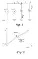
- FIG. 2shows a graph of circuit compliance obtained from empirical data and an estimated circuit compliance approximated from the empirical data
- FIG. 3illustrates a block diagram showing a ventilation system that incorporates a system for circuit compliance compensated volume control
- FIG. 4snows a block diagram of the system for circuit compliance compensated volume control
- FIG. 5illustrates a block diagram of a volume delivery controller of the system as shown in FIG. 4 .
- the electric current Iflows from a high potential level to a low potential level.
- a passive circuit elementsuch as a resistor, an inductor, a capacitor or a load
- a voltage drop ⁇ Vis created across such element.
- two or more of the passive circuit elements of the electric circuitare connected to each other in parallel, the total electric current is split into two smaller currents distributed flowing through the respective elements.
- the magnitudes of the currentsdepend on the characteristic values, such as the resistance, the conductance, and the capacitance of the elements.
- FIG. 1illustrates a circuit diagram of a patient respiratory circuit.
- the patient respiratory circuittypically comprises a patient circuit for circulating gas between a ventilator and a patient.
- the ventilatoris operative to provide an inspiratory gas flow Q INSP and receive an expiratory gas flow Q EXP to and from the patient through the patient circuit, respectively.
- the flow differential between the inspiratory flow Q INSP and the expiratory flow Q EXPis all to be delivered to the patient, so as to provide the tidal volume required thereby.
- the volume loss within the patient circuitis inevitable due to the distensibility at least partially attributed to the circuit compliance C T thereof.
- the circuit compliance C Tis in parallel flow communication with the lung compliance C L and behaves similarly to a capacitor in an electric circuit.
- the machine delivered net volume V NET integrated by the net gas Q NET flow Q NETis equivalent to the tidal volume delivered to the patient.
- the circuit compliance C Tis defined as a ratio of the volume offset by the patient circuit to the pressure across the patient circuit. The offset volume is proportional to the circuit compliance C T . Therefore, when the circuit compliance C T is much larger than the lung compliance C L , a majority of the net flow Q NET will be distributed to the patient circuit instead of being supplied to the patient's lung.
- the patient circuitis connected to a ground pressure level PEEP. Therefore, the pressure across the patient circuit is thus the pressure differential between the pressure measured at a patient piece of the patient circuit P Y and PEEP.
- an airway resistance R Lexists in the patient's airway, such that the pressure applied to the patient's lung will be reduced by a factor of Q L 2 R L .
- the circuit compliance C T and the lung compliance C Lcan be expressed as:
- V TID P L - PEEPV TID P L - PEEP
- V CCV CC P Y - PEEP
- V TIDequivalent to V L
- V CCthe gas volume offset by the circuit compliance.
- the gas volumes V TID and V CCcan be derived by integrating the gas flow Q T and Q L flowing through the patient circuit and the patient's lung L. Therefore, the sum of the gas volumes V CC and V L is equal to the machine delivered net volume V NET as expressed by Equation (4), which can be integrated from the net gas flow Q NET .
- the system and method for circuit compliance compensated volume controlestimate the patient circuit volume and a patient tidal volume using the existing sensors in the ventilator.
- the actual inspiratory gas flow Q INSP and the expiratory gas flow Q EXPare measured by the existing sensors of the ventilator, and the machine delivered net flow Q NET can be derived from the difference thereof. In such manner, various volume variables can be obtained based on the true inhalation and exhalation of the patient.
- the positive end expiratory pressure PEEPis the pressure P Y measured at the end of the expiratory phase. Therefore, before the patient is receiving the machine ventilation, the ground pressure level of the patient circuit is zero or other preset values.
- the circuit compliance C Tcan be predetermined by supplying known volumes to the patient circuit and measuring the responsive circuit pressure at each specific circuit volume.
- FIG. 2shows the relationship between the circuit volume V CC and the pressure differential ⁇ P Y obtained from empirical data.
- Equation (8)a lookup table in which the empirical data of the responsive circuit volumes for various pressures can also be used to estimate the circuit volume V CC .
- a non-linear relationship between the circuit volume and the pressuremay also be obtained and utilized for estimating the circuit volume.
- the net volume delivered by the machine V NETcan be derived by integrating the net flow delivered by the machine Q NET , that is, the difference between the inspiratory and expiratory gas flows Q INSP and Q EXP as:
- V NET⁇ Start ⁇ ⁇ of ⁇ ⁇ I ⁇ - ⁇ phase Q NET ⁇ crosses ⁇ ⁇ 0 ⁇ ( Q INSP - Q EXP ) ⁇ d t . ( 10 )
- the circuit volume V CC and the tidal volume V TIDare estimated at the end of the inspiratory phase.
- FIG. 3illustrates a patient respiratory ventilation circuit or system incorporating the system for circuit compliance compensated volume control as discussed above.
- the ventilation systemincludes a ventilator 10 , a patient circuit 20 for circulating the inspiratory gas and expiratory gas between the ventilator 10 and a patient, the system for circuit compliance compensated volume control 30 , and a servo control subsystem 40 for controlling operations of the ventilator 10 .
- the ventilator 10typically includes a user interface such as a monitor 12 for displaying various conditions and parameters of the patient and the ventilation system, and an input device (not shown) allowing the operator or user to input the required settings and parameters.
- the input devicemay include buttons or any adjusting devices built on the front panel or other devices including keyboard, mouse or remote controls allowing the user to input setup information to the ventilator 10 .
- the monitor 12may be in the form of a touch screen in which both the display and input device are integrated.
- the processoris operative to control the ventilator 10 for performing the desired operations.
- the ventilator 10further includes an inspiratory port 14 and an expiratory port 16 through which the inspiratory gas to the expiratory gas are supplied and received to and from the patient through the patient circuit 20 , respectively.
- An inhalation flow control valve or orificeis typically installed at the inspiratory port 14 for controlling the inspiratory flow Q INSP
- an exhalation valveis preferably installed at the expiratory port 16 for controlling the open/close condition of the expiratory port 16 .
- inspiratory and expiratory flow sensors 11 and 13are installed at the inspiratory and expiratory ports 14 and 16 for measuring the inspiratory Q INSP and expiratory flow Q EXP , respectively.
- an inspiratory pressure transducer 15 and an expiratory pressure transducer 17may also be installed to measure the inspiratory and expiratory pressure P INSP and P EXP , respectively.
- the patient circuit 20such as a Y circuit, is used to connect the ventilator 10 to the patient, so as to construct the respiratory circuit for circulating gas between the ventilator 10 and the patient.
- the Y circuit 20includes an inspiratory limb 22 with one end connected to the inspiratory port 14 and an expiratory limb 24 with one end connected to the expiratory port 16 of the ventilator 10 .
- the other ends of the inspiratory port 14 and the expiratory port 16merge at one end of a patient piece 26 , of which the other end is applied to the patient.
- Other accessories or component devicessuch as filters may also be installed in various part of the Y circuit 20 .
- a flow sensor 28is preferably installed at the patient piece 26 .
- the inspiratory and expiratory flow sensors 11 and 13 and the inspiratory and expiratory pressure transducers 15 and 17may also be installed on the inspiratory limb 22 and expiratory limb 24 , respectively.
- the measurable process variablesincluding the inspiratory flow Q INSP , the expiratory flow Q EXP , the inspiratory pressure P INSP , the expiratory pressure P EXP and the PEEP are sampled by a predetermined frequency. For example, in one embodiment, these processes are sampled every 2 msec.
- the ventilator 10may further comprise a sensor processor 18 operative to process the measured process parameters, including Q INSP , Q EXP , P INSP , P EXP and other sensor readings before outputting to the circuit compliance compensated volume control system 30 .
- the sensor processor 18may includes an individual sensor in communication with the sensors 11 , 13 , 15 , 17 and 28 and the circuit compliance compensated volume control system 30 .
- the sensor processor 18may be integrated into the above-mentioned processor of the ventilator 10 that control the operations of the ventilator 10 .
- the system for circuit compliance compensated volume control 30includes a circuit compliance estimator 31 , a patient circuit volume estimator 32 , a patient volume observer 33 , a volume delivery controller 34 , and a volume to flow converter 35 .
- the circuit compliance C T of the patient circuit 20can be estimated by measuring the pressure differential ⁇ P Y at various given circuit volumes V CC before the patient is receiving the machine ventilation.
- the circuit compliance estimator 31is operative to estimate the circuit compliance C T , such that the relationship between the circuit volume V CC and the pressure differential ⁇ P Y , including the slope CKT_CMP SLP and the intercept CKT_CMP INT , can be also obtained.
- the slope CKT_CMP SLP and the intercept CKT_CMP INT of the circuit compliance estimator 31are then output to the patient circuit volume estimator 32 .
- the circuit volume estimator 32is also connected to the ventilator 10 for receiving the Y circuit pressure P Y and the PEEP measured by the pressure transducer 17 , such that the pressure differential ⁇ P Y can be computed.
- the patient circuit volume V CCcan be estimated by Equation (8) and denoted as VOL CKT — EST output to the patient volume observer 33 .
- the circuit compliance C Tmay also be in the form of a lookup table which provides the responsive pressure differentials for the circuit volumes based on empirical data.
- the patient volume observer 33is operative to receive the measured machine delivered net volume VOL NET , that is, the machine delivered net volume derived by integrating the net flow Q NET , and the estimated circuit volume VOL CKT — EST obtained by the circuit volume estimator 32 .
- the patient volumethat is, the estimated tidal volume VOL TID — EST actually delivered to the patient, is provided by the patient volume observer 33 .
- the estimated circuit volume VOL CKT — EST and the estimated patient volume VOL TID — ESTare updated according to the timing when the net flow Q NET crosses zero instead of the timing when the machine breath cycles from inspiratory phase to expiratory phase.
- the update timing for the volume variableswill be further discussed later.
- the patient flow Q Ycan also be measured.
- the measured patient flow Q Ycan be used to compute a measured patient volume VOL TID — Y for facilitate volume limit of the circuit delivery controller 34 , so as to prevent an excessive circuit compliance compensation volume factor VOL TID — CTL from being generated.
- the measured patient volume VOL TID — Ycan also used to replace the estimated patient volume VOL TID — EST for computing the circuit compliance compensation volume factor VOL TID — CTL .
- the inspiratory flow Q INSPmay also be integrated to obtain the inspiratory volume VOL INSP .
- the net flow Q NET , the patient delivered flow Q Y and the inspiratory flow Q INSPare continuously monitored.
- a zero-crossing net flow Q NETis detected and flagged, while the machine delivered net volume VOL NET , the measured patient volume VOL TID — Y , and the inspiratory volume VOL INSP are continuously updated as:
- VOL NET KVOL NET K-1 +( Q NET K /60)*0.002
- VOL NET Kmax( VOL NET K , 0)
- VOL TID — Y KVOL TID — Y K-1 +( Q Y K /60)*0.002
- VOL TID — Y Kmax( VOL TID — Y K ,
- VOL NET KVOL NET K-1 +( Q NET K /60)*0.002
- VOL NET Kmax( VOL NET K , 0)
- VOL TID — Y KVOL TID — Y K-1 +( Q Y K /60)*0.002
- VOL TID — Y Kmax( VOL TID — Y K , 0)
- VOL INSP KVOL INSP K-1 +( Q INSP K /60)*0.002.
- the estimated patient volume VOL TID — ESTis thus updated according to the timing of the net flow zero-crossing Q NET , such that all the machine delivered net volume VOL NET can be accounted for when the patient breath and the machine breath are out of phase, that is, when the net flow Q NET does not cross zero at the time the machine breath is cycling to the expiratory phase.
- the estimate of the patient volume VOL TID — ESTis subtracted from a set tidal volume VOL TID — SET to obtain a volume error VOL TID — ERR reflecting the error of tidal volume between the setup value and the actual value as estimated.
- the volume error VOL TID — ERRcan thus be used to compute an estimated circuit compliance volume compensation factor VOL TID — CTL by the volume delivery controller 34 to regulate the desired machine/system delivered net volume VOL SYS , so to modulate the inspiratory flow Q 1 — SET of the ventilator 10 .
- the circuit compliance volume compensation factor VOL TID — CTLwill be reset to the initial value INI_CKT_VOL when the user settings of the ventilator 10 are changed. That is, any time when a new set of parameters is input to the system, the circuit compliance volume compensation factor VOL TID — CTL will be reset to the initial value INI_CKT_VOL and updated for every breath.
- the volume delivery controller 34further comprises an error percentage converter 341 , a gain scheduler 342 , and a volume integrator 344 for generating the circuit compliance volume compensation volume factor VOL TID — CTL K for the current breath K.
- the error percentage converter 341is used to compute a ratio of the feedback volume error VOL TID — ERR K to the set tidal volume VOL TID — SET K as:
- VOL PCT_ERR K⁇ VOL TID_ERR K ⁇ VOL TID_SET K ⁇ 100.
- the error percentage VOL PCT — ERR Kprovides a useful indication of the ratio between the circuit compliance C T and the lung compliance C L of the patient. That is, when the error percentage VOL PCT — ERR K is larger, it indicates that a majority of the measured machine delivered net volume VOL NET is distributed to the patient circuit 20 instead of being supplied to the patient's lung. Under such circumstance, a larger amount of volume may be required to compensate for the circuit compliance C T in order to provide the correct machine delivered net volume VOL SYS , so such sufficient volume can be delivered to the patient's lung.
- the volume delivery controller 34further comprises a gain scheduler 342 which receives the error percentage VOL PCT — ERR K and provides a gain K VTID according to the error percentage VOL PCT — ERR K for dynamically weighing the feedback volume error VOL TID — ERR K , so as to according to the error percentage VOL PCT — ERR K .
- a product of the gain K VTID and the volume error VOL PCT — ERR Kis then obtained by a multiplier 343 .
- VOL TID — CTL KK VTID *VOL TID — ERR K +VOL TID — CTL K-1 (20).
- the measured patient volume VOL TID — Ycan be used as a volume limit to prevent the volume delivery controller 34 from generating an excessive volume factor to compensate for the circuit compliance.
- the system for circuit compliance compensated pressure control 30further comprises a volume limiter 37 operative to receive the measured patient volume VOL TID — Y and compare the measured patient volume VOL TID — Y to the set tidal volume VOL TID — SET .
- VOL TID — YBefore the measured patient volume VOL TID — Y reaches a set tidal volume VOL TID — SET preset by the user, that is, when VOL TID — Y ⁇ VOL TID — SET , the volume delivery controller 34 operates normally to generate the circuit compliance volume compensation factor VOL TID CTL based on Equation (20).
- the volume limiter 37is operative to switch on or activate operation of the volume delivery controller 34 when the measured patient volume VOL TID — Y is smaller than the set tidal volume VOL TID — SET , and to switch off or inactivate operation of volume delivery controller as soon as the measured patient volume VOL TID — Y is equal to or exceeds the set tidal volume VOL TID — SET .
- Table Ishows an exemplary gain K VTID set up according to the error percentage VOL PCT — ERR :
- the output VOL TID — CTK K of the volume delivery controller 34is then converted into the a circuit compliance flow compensation factor as Q TID — CTL K by the volume-to-flow converter 35 , such that the inspiratory gas flow Q INSP can be updated to provide the accurate volume to the patient as computed above.
- the inspiratory time T INSP — EST Kis estimated first.
- the set tidal volume VOL TID — SET Kcan be computed by the integration of a predetermined peak inspiratory flow Q PEAK — SET K time t throughout the inspiratory phase.
- the inspiratory tome T INSP — ESTcan be estimated by such relationship.
- the predetermined peak inspiratory flow Q PEAK — SET Kis equal to a preset peak flow Q PEAK — USER K when a square waveform of the inspiratory flow is selected.
- the predetermined peak inspiratory flow Q PEAK — SET Kis a function of the preset peak flow Q PEAK — USER K and the time t into the inspiratory phase. Therefore, dependent on the waveform as selected, the inspiratory time T INSP — EST can be estimated as:
- T ⁇ INSP_EST K⁇ VOL TID_SET K ( Q PEAK_USER / 60 ) , square ⁇ ⁇ waveform ( 4 / 3 ) ⁇ VOL TID_SET K ( Q PEAK_USER / 60 ) , decelerating ⁇ ⁇ waveform , ( 24 )
- Q PEAK_SET K⁇ Q PEAK_USER , square ⁇ ⁇ waveform f ⁇ ( Q PEAK_USSER , t ) , decelerating ⁇ ⁇ waveform . ( 25 )
- the circuit compliance flow compensation factor Q TID — CTL Kcan thus be converted into the flow Q TID — CTL K as:
- the inspiratory volume VOL INSP integrated from the measured inspiratory flow Q INSPcan be used to determine the breath phase of the machine.
- Equation (29)when the measured inspiratory volume VOL INSP is smaller than the updated or desired machine delivered net volume VOL SYS , that is, the set tidal volume VOL TID — SET compensated with the circuit compliance volume compensation factor VOL TID — CTL (VOL TID — SET +VOL TID — CTL ), the machine breath remains at the inspiratory phase.
- the measured inspiratory volume VOL INSPis equal to or larger than the updated machine delivered net volume VOL SYS , the machine breath enters or have entered the expiratory phase, respectively.
- phase⁇ cycle ⁇ ⁇ to ⁇ ⁇ E ⁇ - ⁇ phase
- VOL INSP ⁇ ⁇ K ⁇VOL TID_SET K + VOL TID_CTL K ) remain ⁇ ⁇ in ⁇ ⁇ I ⁇ - ⁇ phase
- VOL INSP K ⁇VOL TID_SET K + VOL TID_CTL K
- the system of circuit compliance compensated volume control 30further comprises a plurality of adders/subtractors 301 , 302 , 303 , and 304 .
- the adder/subtractor 301is operative to receive the inspiratory flow Q INSP and the expiratory flow Q EXP , so as to calculate the net flow Q NET defined as the flow differential therebetween.
- the adder/subtractor 302has two inputs to receive the set tidal volume VOL TID — SET and the estimated patient volume VOL TID — EST from the patient volume observer 32 .
- the difference between the set tidal volume VOL TID — SET and the estimated patient volume VOL TID — ESTthat is, the feedback volume error VOL TID — ERR K defined as the volume differential thereby can be derived and input to the volume delivery controller 34 .
- the adder/subtractor 304bypasses the volume-to-flow converter 35 to calculate the desired machine delivered net volume VOL SYS based on the set tidal volume VOL TID — SET and the circuit compliance volume compensation factor VOL TID — CTL computed by the volume delivery controller 34 .
- the output of the adder/subtractor 304is connected to the servo control subsystem 40 as well as a phase detector 36 , which has another input connected to an integrator 311 for integrating the inspiratory flow Q INSP into the inspiratory volume VOL INSP .
- the phase detector 36is operative to determine the current breath phase of the machine according to Equation (29).
- the adder/subtractor 303has an input connected to the volume-to-flow converter 35 , the other input for receiving the predetermined peak inspiratory flow Q PEAK — SET , and an output connected to the servo control sub-system 40 .
- the desired inspiratory flow Q INSP — SETcan be computed and input to the sub-system servo control system 40 .
- other integrators 312 and 313can also be installed to compute the machine delivered volume VOL NET and the measured patient volume VOL TID — Y when the patient flow Q Y is measured, respectively.
- the measured machine delivered net volume VOL NETis input to the patient volume observer 33 , and the measured tidal volume VOL TID — Y can be used in a volume limiter 37 for controlling the maximum output of the volume delivery controller 34 .
- the measured tidal volume VOL TID — Ycan also be used to replace the estimated patient volume VOL TID — EST for estimating the circuit compliance volume compensation factor VOL TID — CTL
- a switch 38is inserted to selectively connect the adder/subtractor 302 to the integrator 313 or the patient volume observer 33 . By simply operating the switch 38 , the measured patient volume VOL TID — Y or the estimated patient volume VOL TID — EST can be selected as feedback for estimating the circuit compliance volume compensation factor VOL TID — CTL .
- the above adders/subtractors 301 - 304 and integrators 311 - 313may also be formed as individual in the system 30 ; or alternatively, they can also be integrated into the respective devices instead.
- the integrators 311 and 312may be integrated into the phase detector 36 and the patient volume observer 33 , respectively, and the adder/subtractors 301 , 302 and 303 may be integrated as a portion of the patient volume observer 33 , the volume delivery controller 34 , and the servo control sub-system 40 , respectively.
- the adder/subtractor 303may also be integrated at the output of the volume-to-flow converter 35
- the adder/subtractor 304may also be integrated into the output of the volume delivery controller 34 .
- circuit compliance compensated volume control system 30may be implemented by individual hardware or a processor integrated into the ventilator 10 .
- the circuit compliance compensated volume control system 30may also be implemented by a software executable by a personal or laptop computer connected to the ventilator or by the processor of the ventilator 10 directly.
- the desired inspiratory flow Q I — SET and the desired machine delivered volume VOL SYSare input to the servo control subsystem 40 , which, according to the desired inspiratory flow Q I — SET , generate a flow-control valve command signal FCV D/A to control the orifice of the inspiratory port 14 , so as to command the ventilator 10 to deliver the desired inspiratory flow Q I — SET .
- the servo control subsystem 40is also operative to generate an exhalation valve command signal EV D/A to control opening or closing status of the exhalation port 16 .
Landscapes
- Health & Medical Sciences (AREA)
- Emergency Medicine (AREA)
- Pulmonology (AREA)
- Engineering & Computer Science (AREA)
- Anesthesiology (AREA)
- Biomedical Technology (AREA)
- Heart & Thoracic Surgery (AREA)
- Hematology (AREA)
- Life Sciences & Earth Sciences (AREA)
- Animal Behavior & Ethology (AREA)
- General Health & Medical Sciences (AREA)
- Public Health (AREA)
- Veterinary Medicine (AREA)
- Measurement Of The Respiration, Hearing Ability, Form, And Blood Characteristics Of Living Organisms (AREA)
Abstract
Description
PY=PL+QL2RL (1)
By definition, the circuit compliance CTand the lung compliance CLcan be expressed as:
where VTIDis equivalent to VL, which is the actual gas volume delivered to the lung of the patient, and VCCis the gas volume offset by the circuit compliance. The gas volumes VTIDand VCCcan be derived by integrating the gas flow QTand QLflowing through the patient circuit and the patient's lung L. Therefore, the sum of the gas volumes VCCand VLis equal to the machine delivered net volume VNETas expressed by Equation (4), which can be integrated from the net gas flow QNET.
VNET=VCC+VTID (4)
From Equations (3) and (4), an estimate of patient volume can be expressed as:
{circumflex over (V)}TID=VNET−VCC=VNET−CT(PY−PEEP) (5)
From Equations (1) and (2),
From Equations (5) and (6), an estimate of the net volume that the ventilator needs to deliver is:
From Equation (7), the machine delivered net volume VNETcan be computed if the lung compliance CL, the circuit compliance CT, the airway resistance RL, the desired patient flow QL, and the desired patient flow VTIDare known. It will be appreciated that, as the volume parameters in Equation (7) are integrations of the corresponding gas flows, the pressure parameter PYtypically indicates the peak pressure at the patient circuit.
{circumflex over (V)}CC=CKT—CMPSLP·(PY−PEEP)+CKT—CMPINT (8)
where CKT_CMPINTis the intercept with the VCCaxis. It will be appreciated that, in addition to mathematical formula as provided in Equation (8), a lookup table in which the empirical data of the responsive circuit volumes for various pressures can also be used to estimate the circuit volume VCC. In addition, according to specific condition, a non-linear relationship between the circuit volume and the pressure may also be obtained and utilized for estimating the circuit volume.
{circumflex over (V)}TID=VNET−{circumflex over (V)}CC (9)
As mentioned above, the net volume delivered by the machine VNETcan be derived by integrating the net flow delivered by the machine QNET, that is, the difference between the inspiratory and expiratory gas flows QINSPand QEXPas:
In this embodiment, the circuit volume VCCwill not be updated until the differential gas flow, that is, the net gas flow QNET(=QINSP−QEXP), crosses zero; and therefore, the calculation or computation of the net machine delivered volume VNETis integrated over the differential gas flow QNETfrom the start of the inspiratory phase to the time when the net flow QNETcrosses 0. In the case that the net flow QNETcrosses 0 before the inspiratory phase is complete, the circuit volume VCCand the tidal volume VTIDare estimated at the end of the inspiratory phase.
VOLNET
VOLTID
VOLCKT
where K is an index indicating the sampling number of the above volume variables. The sampling interval for these volume variables is determined based on factors such as the individual ventilator settings and the patient conditions.
VOLTID
VOLINSP
VOLNET
VOLTID
VOLINSP
VOLNET
VOLTID
VOLINSP
{circumflex over (V)}OLCKT
{circumflex over (V)}OLTID
{circumflex over (V)}OLTID
and the machine delivered net volume VOLNETand measured patient volume VOLTID
VOLNET
VOLTID
VOLNET
VOLTID
VOLINSP
VOLNET
VOLTID
In this embodiment, the measured machine delivered net volume VOLNETand the measured patient volume VOLTID
VOLTID
The circuit compliance volume compensation factor VOLTID
The error percentage VOLPCT
VOLTID
VOLTID
VOLTID
and the output of the
VOLTID
Effectively, the
| TABLE I | |||
| KVTID | VOLPCT—ERR | ||
| 1 | 0 | ||
| 2 | 25% | ||
| 2.5 | 50% | ||
| 4 | 100% | ||
| 4 | 150% | ||
According to Table I, when the error percentage VOLPCT
where
The circuit compliance flow compensation factor QTID
Therefore, the required inspiratory flow QINSP
QI
while the overall commanded volume to be used by the servo-
VOLSYS
Claims (51)
Priority Applications (5)
| Application Number | Priority Date | Filing Date | Title |
|---|---|---|---|
| US11/247,568US7886739B2 (en) | 2005-10-11 | 2005-10-11 | System and method for circuit compliance compensated volume control in a patient respiratory ventilator |
| JP2008535585AJP4991732B2 (en) | 2005-10-11 | 2006-10-06 | System and method for circuit compliance compensated volume control in a patient respiratory ventilator |
| PCT/US2006/039194WO2007047172A2 (en) | 2005-10-11 | 2006-10-06 | System and method for circuit compliance compensated volume control in a patient respiratory ventilator |
| EP06825578.5AEP1933911B1 (en) | 2005-10-11 | 2006-10-06 | System for circuit compliance compensated volume control in a patient respiratory ventilator |
| CN200680037817XACN101365507B (en) | 2005-10-11 | 2006-10-06 | Circuit compliance compensation volume control system and method in ventilator for patient breathing |
Applications Claiming Priority (1)
| Application Number | Priority Date | Filing Date | Title |
|---|---|---|---|
| US11/247,568US7886739B2 (en) | 2005-10-11 | 2005-10-11 | System and method for circuit compliance compensated volume control in a patient respiratory ventilator |
Publications (2)
| Publication Number | Publication Date |
|---|---|
| US20070089738A1 US20070089738A1 (en) | 2007-04-26 |
| US7886739B2true US7886739B2 (en) | 2011-02-15 |
Family
ID=37963016
Family Applications (1)
| Application Number | Title | Priority Date | Filing Date |
|---|---|---|---|
| US11/247,568Active2029-08-13US7886739B2 (en) | 2005-10-11 | 2005-10-11 | System and method for circuit compliance compensated volume control in a patient respiratory ventilator |
Country Status (5)
| Country | Link |
|---|---|
| US (1) | US7886739B2 (en) |
| EP (1) | EP1933911B1 (en) |
| JP (1) | JP4991732B2 (en) |
| CN (1) | CN101365507B (en) |
| WO (1) | WO2007047172A2 (en) |
Cited By (30)
| Publication number | Priority date | Publication date | Assignee | Title |
|---|---|---|---|---|
| US20090241955A1 (en)* | 2008-03-31 | 2009-10-01 | Nellcor Puritan Bennett Llc | Leak-compensated flow triggering and cycling in medical ventilators |
| US20100071696A1 (en)* | 2008-09-25 | 2010-03-25 | Nellcor Puritan Bennett Llc | Model-predictive online identification of patient respiratory effort dynamics in medical ventilators |
| US20100147303A1 (en)* | 2008-03-31 | 2010-06-17 | Nellcor Puritan Bennett Llc | Determination of patient circuit disconnect in leak-compensated ventilatory support |
| US20100218767A1 (en)* | 2009-02-27 | 2010-09-02 | Nellcor Puritan Bennett Llc | Leak-compensated respiratory mechanics estimation in medical ventilators |
| US20100236555A1 (en)* | 2009-03-20 | 2010-09-23 | Nellcor Puritan Bennett Llc | Leak-compensated pressure regulated volume control ventilation |
| US20100236553A1 (en)* | 2009-03-20 | 2010-09-23 | Nellcor Puritan Bennelt LLC | Leak-compensated proportional assist ventilation |
| US20110273299A1 (en)* | 2010-05-07 | 2011-11-10 | Nellcor Puritan Bennett Llc | Ventilator-Initiated Prompt Regarding Auto-PEEP Detection During Volume Ventilation Of Non-Triggering Patient |
| US20120226444A1 (en)* | 2011-03-02 | 2012-09-06 | Nellcor Puritan Bennett Llc | Ventilator-Initiated Prompt Regarding High Delivered Tidal Volume |
| US8595639B2 (en) | 2010-11-29 | 2013-11-26 | Covidien Lp | Ventilator-initiated prompt regarding detection of fluctuations in resistance |
| US8607789B2 (en) | 2010-06-30 | 2013-12-17 | Covidien Lp | Ventilator-initiated prompt regarding auto-PEEP detection during volume ventilation of non-triggering patient exhibiting obstructive component |
| US8607791B2 (en) | 2010-06-30 | 2013-12-17 | Covidien Lp | Ventilator-initiated prompt regarding auto-PEEP detection during pressure ventilation |
| US8607790B2 (en) | 2010-06-30 | 2013-12-17 | Covidien Lp | Ventilator-initiated prompt regarding auto-PEEP detection during pressure ventilation of patient exhibiting obstructive component |
| US8607788B2 (en) | 2010-06-30 | 2013-12-17 | Covidien Lp | Ventilator-initiated prompt regarding auto-PEEP detection during volume ventilation of triggering patient exhibiting obstructive component |
| US8757152B2 (en) | 2010-11-29 | 2014-06-24 | Covidien Lp | Ventilator-initiated prompt regarding detection of double triggering during a volume-control breath type |
| US8757153B2 (en) | 2010-11-29 | 2014-06-24 | Covidien Lp | Ventilator-initiated prompt regarding detection of double triggering during ventilation |
| US8776792B2 (en) | 2011-04-29 | 2014-07-15 | Covidien Lp | Methods and systems for volume-targeted minimum pressure-control ventilation |
| US8844526B2 (en) | 2012-03-30 | 2014-09-30 | Covidien Lp | Methods and systems for triggering with unknown base flow |
| US9022031B2 (en) | 2012-01-31 | 2015-05-05 | Covidien Lp | Using estimated carinal pressure for feedback control of carinal pressure during ventilation |
| US9027552B2 (en) | 2012-07-31 | 2015-05-12 | Covidien Lp | Ventilator-initiated prompt or setting regarding detection of asynchrony during ventilation |
| US9364624B2 (en) | 2011-12-07 | 2016-06-14 | Covidien Lp | Methods and systems for adaptive base flow |
| US9492629B2 (en) | 2013-02-14 | 2016-11-15 | Covidien Lp | Methods and systems for ventilation with unknown exhalation flow and exhalation pressure |
| US9498589B2 (en) | 2011-12-31 | 2016-11-22 | Covidien Lp | Methods and systems for adaptive base flow and leak compensation |
| US9649458B2 (en) | 2008-09-30 | 2017-05-16 | Covidien Lp | Breathing assistance system with multiple pressure sensors |
| US9675771B2 (en) | 2013-10-18 | 2017-06-13 | Covidien Lp | Methods and systems for leak estimation |
| US9925346B2 (en) | 2015-01-20 | 2018-03-27 | Covidien Lp | Systems and methods for ventilation with unknown exhalation flow |
| US9981096B2 (en) | 2013-03-13 | 2018-05-29 | Covidien Lp | Methods and systems for triggering with unknown inspiratory flow |
| US10207069B2 (en) | 2008-03-31 | 2019-02-19 | Covidien Lp | System and method for determining ventilator leakage during stable periods within a breath |
| US10434270B2 (en) | 2011-12-27 | 2019-10-08 | Koninklijke Philips N.V. | Compensation of breath delivery |
| US10905836B2 (en) | 2015-04-02 | 2021-02-02 | Hill-Rom Services Pte. Ltd. | Manifold for respiratory device |
| US11419996B2 (en)* | 2017-11-07 | 2022-08-23 | Loewenstein Medical Technology S.A. | Device for respiration by using a tubus |
Families Citing this family (31)
| Publication number | Priority date | Publication date | Assignee | Title |
|---|---|---|---|---|
| US8474455B2 (en)* | 2006-01-10 | 2013-07-02 | Carefusion 207, Inc. | System and method for circuit compliance compensated volume assured pressure control in a patient respiratory ventilator |
| ATE479460T1 (en)* | 2006-01-30 | 2010-09-15 | Hamilton Medical Ag | O2 CONTROL |
| WO2009149357A1 (en) | 2008-06-06 | 2009-12-10 | Nellcor Puritan Bennett Llc | Systems and methods for ventilation in proportion to patient effort |
| US9314579B2 (en) | 2008-10-17 | 2016-04-19 | Koninklijke Philips N.V. | Porting block for a medical ventilator |
| EP2416706B1 (en)* | 2009-04-08 | 2017-01-11 | Koninklijke Philips N.V. | System for providing feedback to a subject regarding reception of positive airway support therapy |
| US8707952B2 (en) | 2010-02-10 | 2014-04-29 | Covidien Lp | Leak determination in a breathing assistance system |
| CN102892449B (en)* | 2010-05-11 | 2016-04-20 | 皇家飞利浦电子股份有限公司 | Inductance in pressure support system compensates |
| EP2608832B1 (en) | 2010-08-27 | 2022-09-28 | ResMed Pty Ltd | Adaptive cycling for respiratory treatment apparatus |
| CN102397609A (en)* | 2010-09-07 | 2012-04-04 | 北京航天长峰股份有限公司 | Volume-guaranteed pressure-limited ventilation method for anesthesia machine and respirator |
| CN102397610B (en)* | 2010-09-07 | 2015-03-25 | 北京航天长峰股份有限公司 | Method for adjusting gradient of slope under anesthesia machine and breathing machine pressure control |
| CN102266622B (en)* | 2010-12-31 | 2014-06-11 | 北京谊安医疗系统股份有限公司 | Startup self-checking method and device for anaesthesia machine |
| US8714154B2 (en) | 2011-03-30 | 2014-05-06 | Covidien Lp | Systems and methods for automatic adjustment of ventilator settings |
| CN103071221B (en)* | 2011-10-25 | 2015-07-22 | 北京航天长峰股份有限公司 | Compliance compensation capacity guaranteeing method for anesthesia machine and respirator |
| US10362967B2 (en) | 2012-07-09 | 2019-07-30 | Covidien Lp | Systems and methods for missed breath detection and indication |
| CN103908713B (en)* | 2012-12-29 | 2017-06-06 | 北京谊安医疗系统股份有限公司 | A kind of detection method of Anesthesia machine or respirator system compliance |
| US9950129B2 (en) | 2014-10-27 | 2018-04-24 | Covidien Lp | Ventilation triggering using change-point detection |
| RU2712843C2 (en)* | 2014-12-24 | 2020-01-31 | Конинклейке Филипс Н.В. | Systems and methods for detecting disconnection of artificial pulmonary ventilation apparatus from patient using assessment of lung compliance of patient's lungs on respiratory phases of inhalation and exhalation |
| CN104771818B (en)* | 2015-03-02 | 2017-03-01 | 深圳市科曼医疗设备有限公司 | Per nasal pressure generator self-adapting calibration system and method |
| CN107787238B (en)* | 2015-06-25 | 2020-08-07 | 马奎特紧急护理公司 | Oxygenation during mechanical ventilation of a patient |
| CN106345020B (en)* | 2015-07-15 | 2019-05-17 | 北京谊安医疗系统股份有限公司 | The control method of pressure control capability mode in a kind of ventilator |
| US11027082B2 (en)* | 2015-09-28 | 2021-06-08 | Koninklijke Philps N.V. | Methods and systems to estimate compliance of a patient circuit in the presence of leak |
| CN105183024B (en)* | 2015-10-09 | 2019-01-29 | 航宇救生装备有限公司 | A kind of flow rate pressure two close cycles gas pressure control method and device |
| US11191447B2 (en)* | 2015-11-02 | 2021-12-07 | Koninklijke Philips N.V. | Breath by breath reassessment of patient lung parameters to improve estimation performance |
| CN106913946A (en)* | 2015-12-25 | 2017-07-04 | 北京谊安医疗系统股份有限公司 | A kind of method that tidal volume is adjusted under IPPV ventilating modes |
| EP4233951B1 (en) | 2017-05-12 | 2025-03-05 | ResMed Pty Ltd | Apparatus for treatment of respiratory disorders |
| US11324954B2 (en) | 2019-06-28 | 2022-05-10 | Covidien Lp | Achieving smooth breathing by modified bilateral phrenic nerve pacing |
| US12233210B2 (en)* | 2020-06-11 | 2025-02-25 | Koninklijke Philips N.V. | Method of delivering variable ventilation with AVAPS |
| US12257437B2 (en) | 2020-09-30 | 2025-03-25 | Covidien Lp | Intravenous phrenic nerve stimulation lead |
| CN112827030B (en)* | 2021-01-06 | 2023-02-28 | 北京谊安医疗系统股份有限公司 | Expiratory pressure automatic titration method and system based on expiratory airflow limitation index |
| CN114377258B (en)* | 2021-12-21 | 2023-09-19 | 北京谊安医疗系统股份有限公司 | Control device and control method for basic flow of neonate breathing machine |
| CN116020031B (en)* | 2023-03-27 | 2023-06-27 | 广州国家实验室 | Constant volume control method, system and device for breathing machine and storage medium |
Citations (2)
| Publication number | Priority date | Publication date | Assignee | Title |
|---|---|---|---|---|
| US5881717A (en) | 1997-03-14 | 1999-03-16 | Nellcor Puritan Bennett Incorporated | System and method for adjustable disconnection sensitivity for disconnection and occlusion detection in a patient ventilator |
| US6305374B1 (en)* | 1989-09-22 | 2001-10-23 | Respironics, Inc. | Breathing gas delivery method and apparatus |
Family Cites Families (11)
| Publication number | Priority date | Publication date | Assignee | Title |
|---|---|---|---|---|
| US3834381A (en)* | 1972-08-25 | 1974-09-10 | Puritan Bennett Corp | Compliance compensated ventilation system |
| US3923056A (en)* | 1974-06-19 | 1975-12-02 | Gen Electric | Compliance compensation for electronically controlled volume respirator systems |
| DE2505670B2 (en)* | 1975-02-11 | 1978-11-30 | Draegerwerk Ag, 2400 Luebeck | Ventilation system |
| US4211121A (en)* | 1976-09-01 | 1980-07-08 | Fmc Corporation | Vibrator with eccentric weights |
| DE2746924C2 (en)* | 1977-10-19 | 1982-09-16 | Drägerwerk AG, 2400 Lübeck | Ventilator |
| US4448192A (en)* | 1982-03-05 | 1984-05-15 | Hewlett Packard Company | Medical ventilator device parametrically controlled for patient ventilation |
| JPH0390164A (en)* | 1989-06-16 | 1991-04-16 | Manabu Akashi | Artificial respiration device for controlling flow rate and pressure in circuit matched with respiration flow rate of patient |
| SE9602913D0 (en)* | 1996-08-02 | 1996-08-02 | Siemens Elema Ab | Fan system and method of operating a fan system |
| US6142150A (en)* | 1998-03-24 | 2000-11-07 | Nellcor Puritan-Bennett | Compliance compensation in volume control ventilator |
| SE9802122D0 (en)* | 1998-06-15 | 1998-06-15 | Siemens Elema Ab | Volume determination method |
| US6557553B1 (en)* | 2000-09-05 | 2003-05-06 | Mallinckrodt, Inc. | Adaptive inverse control of pressure based ventilation |
- 2005
- 2005-10-11USUS11/247,568patent/US7886739B2/enactiveActive
- 2006
- 2006-10-06JPJP2008535585Apatent/JP4991732B2/enactiveActive
- 2006-10-06CNCN200680037817XApatent/CN101365507B/enactiveActive
- 2006-10-06EPEP06825578.5Apatent/EP1933911B1/enactiveActive
- 2006-10-06WOPCT/US2006/039194patent/WO2007047172A2/enactiveApplication Filing
Patent Citations (2)
| Publication number | Priority date | Publication date | Assignee | Title |
|---|---|---|---|---|
| US6305374B1 (en)* | 1989-09-22 | 2001-10-23 | Respironics, Inc. | Breathing gas delivery method and apparatus |
| US5881717A (en) | 1997-03-14 | 1999-03-16 | Nellcor Puritan Bennett Incorporated | System and method for adjustable disconnection sensitivity for disconnection and occlusion detection in a patient ventilator |
Cited By (56)
| Publication number | Priority date | Publication date | Assignee | Title |
|---|---|---|---|---|
| US10207069B2 (en) | 2008-03-31 | 2019-02-19 | Covidien Lp | System and method for determining ventilator leakage during stable periods within a breath |
| US8272379B2 (en) | 2008-03-31 | 2012-09-25 | Nellcor Puritan Bennett, Llc | Leak-compensated flow triggering and cycling in medical ventilators |
| US8272380B2 (en) | 2008-03-31 | 2012-09-25 | Nellcor Puritan Bennett, Llc | Leak-compensated pressure triggering in medical ventilators |
| US20100147303A1 (en)* | 2008-03-31 | 2010-06-17 | Nellcor Puritan Bennett Llc | Determination of patient circuit disconnect in leak-compensated ventilatory support |
| US8434480B2 (en) | 2008-03-31 | 2013-05-07 | Covidien Lp | Ventilator leak compensation |
| US11027080B2 (en) | 2008-03-31 | 2021-06-08 | Covidien Lp | System and method for determining ventilator leakage during stable periods within a breath |
| US9421338B2 (en) | 2008-03-31 | 2016-08-23 | Covidien Lp | Ventilator leak compensation |
| US8746248B2 (en) | 2008-03-31 | 2014-06-10 | Covidien Lp | Determination of patient circuit disconnect in leak-compensated ventilatory support |
| US20090241962A1 (en)* | 2008-03-31 | 2009-10-01 | Nellcor Puritan Bennett Llc | Ventilator leak compensation |
| US20090241955A1 (en)* | 2008-03-31 | 2009-10-01 | Nellcor Puritan Bennett Llc | Leak-compensated flow triggering and cycling in medical ventilators |
| US20100071696A1 (en)* | 2008-09-25 | 2010-03-25 | Nellcor Puritan Bennett Llc | Model-predictive online identification of patient respiratory effort dynamics in medical ventilators |
| US9649458B2 (en) | 2008-09-30 | 2017-05-16 | Covidien Lp | Breathing assistance system with multiple pressure sensors |
| US20100218767A1 (en)* | 2009-02-27 | 2010-09-02 | Nellcor Puritan Bennett Llc | Leak-compensated respiratory mechanics estimation in medical ventilators |
| US8424521B2 (en) | 2009-02-27 | 2013-04-23 | Covidien Lp | Leak-compensated respiratory mechanics estimation in medical ventilators |
| US8978650B2 (en) | 2009-03-20 | 2015-03-17 | Covidien Lp | Leak-compensated proportional assist ventilation |
| US8448641B2 (en) | 2009-03-20 | 2013-05-28 | Covidien Lp | Leak-compensated proportional assist ventilation |
| US20100236553A1 (en)* | 2009-03-20 | 2010-09-23 | Nellcor Puritan Bennelt LLC | Leak-compensated proportional assist ventilation |
| US8267085B2 (en) | 2009-03-20 | 2012-09-18 | Nellcor Puritan Bennett Llc | Leak-compensated proportional assist ventilation |
| US8973577B2 (en) | 2009-03-20 | 2015-03-10 | Covidien Lp | Leak-compensated pressure regulated volume control ventilation |
| US8418691B2 (en) | 2009-03-20 | 2013-04-16 | Covidien Lp | Leak-compensated pressure regulated volume control ventilation |
| US20100236555A1 (en)* | 2009-03-20 | 2010-09-23 | Nellcor Puritan Bennett Llc | Leak-compensated pressure regulated volume control ventilation |
| US9030304B2 (en) | 2010-05-07 | 2015-05-12 | Covidien Lp | Ventilator-initiated prompt regarding auto-peep detection during ventilation of non-triggering patient |
| US20110273299A1 (en)* | 2010-05-07 | 2011-11-10 | Nellcor Puritan Bennett Llc | Ventilator-Initiated Prompt Regarding Auto-PEEP Detection During Volume Ventilation Of Non-Triggering Patient |
| US8638200B2 (en)* | 2010-05-07 | 2014-01-28 | Covidien Lp | Ventilator-initiated prompt regarding Auto-PEEP detection during volume ventilation of non-triggering patient |
| US8607790B2 (en) | 2010-06-30 | 2013-12-17 | Covidien Lp | Ventilator-initiated prompt regarding auto-PEEP detection during pressure ventilation of patient exhibiting obstructive component |
| US8607788B2 (en) | 2010-06-30 | 2013-12-17 | Covidien Lp | Ventilator-initiated prompt regarding auto-PEEP detection during volume ventilation of triggering patient exhibiting obstructive component |
| US8607791B2 (en) | 2010-06-30 | 2013-12-17 | Covidien Lp | Ventilator-initiated prompt regarding auto-PEEP detection during pressure ventilation |
| US8607789B2 (en) | 2010-06-30 | 2013-12-17 | Covidien Lp | Ventilator-initiated prompt regarding auto-PEEP detection during volume ventilation of non-triggering patient exhibiting obstructive component |
| US8757153B2 (en) | 2010-11-29 | 2014-06-24 | Covidien Lp | Ventilator-initiated prompt regarding detection of double triggering during ventilation |
| US8757152B2 (en) | 2010-11-29 | 2014-06-24 | Covidien Lp | Ventilator-initiated prompt regarding detection of double triggering during a volume-control breath type |
| US8595639B2 (en) | 2010-11-29 | 2013-11-26 | Covidien Lp | Ventilator-initiated prompt regarding detection of fluctuations in resistance |
| US20120226444A1 (en)* | 2011-03-02 | 2012-09-06 | Nellcor Puritan Bennett Llc | Ventilator-Initiated Prompt Regarding High Delivered Tidal Volume |
| US9038633B2 (en)* | 2011-03-02 | 2015-05-26 | Covidien Lp | Ventilator-initiated prompt regarding high delivered tidal volume |
| US20150224272A1 (en)* | 2011-03-02 | 2015-08-13 | Covidien Lp | Ventilator-initiated prompt regarding high-delivered tidal volume |
| US8776792B2 (en) | 2011-04-29 | 2014-07-15 | Covidien Lp | Methods and systems for volume-targeted minimum pressure-control ventilation |
| US11497869B2 (en) | 2011-12-07 | 2022-11-15 | Covidien Lp | Methods and systems for adaptive base flow |
| US9364624B2 (en) | 2011-12-07 | 2016-06-14 | Covidien Lp | Methods and systems for adaptive base flow |
| US10543327B2 (en) | 2011-12-07 | 2020-01-28 | Covidien Lp | Methods and systems for adaptive base flow |
| US10434270B2 (en) | 2011-12-27 | 2019-10-08 | Koninklijke Philips N.V. | Compensation of breath delivery |
| US11833297B2 (en) | 2011-12-31 | 2023-12-05 | Covidien Lp | Methods and systems for adaptive base flow and leak compensation |
| US9498589B2 (en) | 2011-12-31 | 2016-11-22 | Covidien Lp | Methods and systems for adaptive base flow and leak compensation |
| US10709854B2 (en) | 2011-12-31 | 2020-07-14 | Covidien Lp | Methods and systems for adaptive base flow and leak compensation |
| US9022031B2 (en) | 2012-01-31 | 2015-05-05 | Covidien Lp | Using estimated carinal pressure for feedback control of carinal pressure during ventilation |
| US8844526B2 (en) | 2012-03-30 | 2014-09-30 | Covidien Lp | Methods and systems for triggering with unknown base flow |
| US10029057B2 (en) | 2012-03-30 | 2018-07-24 | Covidien Lp | Methods and systems for triggering with unknown base flow |
| US9027552B2 (en) | 2012-07-31 | 2015-05-12 | Covidien Lp | Ventilator-initiated prompt or setting regarding detection of asynchrony during ventilation |
| US9492629B2 (en) | 2013-02-14 | 2016-11-15 | Covidien Lp | Methods and systems for ventilation with unknown exhalation flow and exhalation pressure |
| US9981096B2 (en) | 2013-03-13 | 2018-05-29 | Covidien Lp | Methods and systems for triggering with unknown inspiratory flow |
| US10207068B2 (en) | 2013-10-18 | 2019-02-19 | Covidien Lp | Methods and systems for leak estimation |
| US9675771B2 (en) | 2013-10-18 | 2017-06-13 | Covidien Lp | Methods and systems for leak estimation |
| US11235114B2 (en) | 2013-10-18 | 2022-02-01 | Covidien Lp | Methods and systems for leak estimation |
| US9925346B2 (en) | 2015-01-20 | 2018-03-27 | Covidien Lp | Systems and methods for ventilation with unknown exhalation flow |
| US10905836B2 (en) | 2015-04-02 | 2021-02-02 | Hill-Rom Services Pte. Ltd. | Manifold for respiratory device |
| US10905837B2 (en) | 2015-04-02 | 2021-02-02 | Hill-Rom Services Pte. Ltd. | Respiratory therapy cycle control and feedback |
| US11992611B2 (en) | 2015-04-02 | 2024-05-28 | Hill-Rom Services Pte. Ltd. | Respiratory therapy apparatus control |
| US11419996B2 (en)* | 2017-11-07 | 2022-08-23 | Loewenstein Medical Technology S.A. | Device for respiration by using a tubus |
Also Published As
| Publication number | Publication date |
|---|---|
| CN101365507A (en) | 2009-02-11 |
| CN101365507B (en) | 2013-03-06 |
| JP4991732B2 (en) | 2012-08-01 |
| JP2009511174A (en) | 2009-03-19 |
| EP1933911A4 (en) | 2011-12-28 |
| WO2007047172A3 (en) | 2007-12-13 |
| US20070089738A1 (en) | 2007-04-26 |
| EP1933911B1 (en) | 2017-03-29 |
| EP1933911A2 (en) | 2008-06-25 |
| WO2007047172A2 (en) | 2007-04-26 |
Similar Documents
| Publication | Publication Date | Title |
|---|---|---|
| US7886739B2 (en) | System and method for circuit compliance compensated volume control in a patient respiratory ventilator | |
| US7918223B2 (en) | System and method for circuit compliance compensated pressure-regulated volume control in a patient respiratory ventilator | |
| US8474455B2 (en) | System and method for circuit compliance compensated volume assured pressure control in a patient respiratory ventilator | |
| US11235114B2 (en) | Methods and systems for leak estimation | |
| US8418691B2 (en) | Leak-compensated pressure regulated volume control ventilation | |
| US11027080B2 (en) | System and method for determining ventilator leakage during stable periods within a breath | |
| US6557553B1 (en) | Adaptive inverse control of pressure based ventilation | |
| US8448641B2 (en) | Leak-compensated proportional assist ventilation | |
| US10029057B2 (en) | Methods and systems for triggering with unknown base flow | |
| US8272380B2 (en) | Leak-compensated pressure triggering in medical ventilators | |
| US20150090264A1 (en) | Methods and systems for proportional assist ventilation | |
| EP2259820B1 (en) | Leak-compensated proportional assist ventilation | |
| US9925346B2 (en) | Systems and methods for ventilation with unknown exhalation flow | |
| US20070151563A1 (en) | Apparatus and method for controlling gas-delivery mechanism for use in respiratory ventilators | |
| US20220096764A1 (en) | Synchronized high-flow system |
Legal Events
| Date | Code | Title | Description |
|---|---|---|---|
| AS | Assignment | Owner name:VIASYS MANUFACTURING INC., PENNSYLVANIA Free format text:ASSIGNMENT OF ASSIGNORS INTEREST;ASSIGNORS:SOLIMAN, IHAB S.;DUQUETTE, STEVEN;REEL/FRAME:017237/0163 Effective date:20051103 | |
| AS | Assignment | Owner name:CARDINAL HEALTH 207, INC., PENNSYLVANIA Free format text:CHANGE OF NAME;ASSIGNOR:VIASYS MANUFACTURING, INC.;REEL/FRAME:022624/0311 Effective date:20071016 | |
| AS | Assignment | Owner name:CAREFUSION 207, INC.,CALIFORNIA Free format text:CHANGE OF NAME;ASSIGNOR:CARDINAL HEALTH 207, INC.;REEL/FRAME:024264/0389 Effective date:20090729 Owner name:CAREFUSION 207, INC., CALIFORNIA Free format text:CHANGE OF NAME;ASSIGNOR:CARDINAL HEALTH 207, INC.;REEL/FRAME:024264/0389 Effective date:20090729 | |
| STCF | Information on status: patent grant | Free format text:PATENTED CASE | |
| FPAY | Fee payment | Year of fee payment:4 | |
| AS | Assignment | Owner name:BANK OF AMERICA, N.A., AS COLLATERAL AGENT, NORTH Free format text:FIRST LIEN SECURITY AGREEMENT;ASSIGNOR:CAREFUSION 207, INC.;REEL/FRAME:045968/0497 Effective date:20180416 Owner name:WILMINGTON TRUST, NATIONAL ASSOCIATION, AS COLLATE Free format text:SECOND LIEN SECURITY AGREEMENT;ASSIGNOR:CAREFUSION 207, INC.;REEL/FRAME:045969/0482 Effective date:20180416 | |
| MAFP | Maintenance fee payment | Free format text:PAYMENT OF MAINTENANCE FEE, 8TH YEAR, LARGE ENTITY (ORIGINAL EVENT CODE: M1552) Year of fee payment:8 | |
| AS | Assignment | Owner name:WILMINGTON TRUST, NATIONAL ASSOCIATION, MINNESOTA Free format text:SECURITY INTEREST;ASSIGNOR:CAREFUSION 207, INC.;REEL/FRAME:049109/0656 Effective date:20190503 | |
| AS | Assignment | Owner name:VYAIRE MEDICAL 207, INC., ILLINOIS Free format text:CHANGE OF NAME;ASSIGNOR:CAREFUSION 207, INC.;REEL/FRAME:059852/0577 Effective date:20210401 | |
| MAFP | Maintenance fee payment | Free format text:PAYMENT OF MAINTENANCE FEE, 12TH YEAR, LARGE ENTITY (ORIGINAL EVENT CODE: M1553); ENTITY STATUS OF PATENT OWNER: LARGE ENTITY Year of fee payment:12 | |
| AS | Assignment | Owner name:VYAIRE MEDICAL 211, INC., ILLINOIS Free format text:MERGER;ASSIGNOR:VYAIRE MEDICAL 207, INC.;REEL/FRAME:061329/0785 Effective date:20220411 | |
| AS | Assignment | Owner name:ZOLL MEDICAL CORPORATION, MASSACHUSETTS Free format text:ASSIGNMENT OF ASSIGNORS INTEREST;ASSIGNOR:VYAIRE MEDICAL 211, INC.;REEL/FRAME:069454/0907 Effective date:20241011 | |
| AS | Assignment | Owner name:ZOLL MEDICAL CORPORATION, MASSACHUSETTS Free format text:RELEASE BY SECURED PARTY;ASSIGNOR:VYAIRE MEDICAL, INC., ET AL.'S CREDITORS;REEL/FRAME:069635/0201 Effective date:20240903 |