US7886388B2 - Mattress adapted for supporting heavy weight persons - Google Patents
Mattress adapted for supporting heavy weight personsDownload PDFInfo
- Publication number
- US7886388B2 US7886388B2US12/429,778US42977809AUS7886388B2US 7886388 B2US7886388 B2US 7886388B2US 42977809 AUS42977809 AUS 42977809AUS 7886388 B2US7886388 B2US 7886388B2
- Authority
- US
- United States
- Prior art keywords
- foam layer
- foam
- mattress
- layer
- define
- Prior art date
- Legal status (The legal status is an assumption and is not a legal conclusion. Google has not performed a legal analysis and makes no representation as to the accuracy of the status listed.)
- Active
Links
Images


Classifications
- A—HUMAN NECESSITIES
- A47—FURNITURE; DOMESTIC ARTICLES OR APPLIANCES; COFFEE MILLS; SPICE MILLS; SUCTION CLEANERS IN GENERAL
- A47C—CHAIRS; SOFAS; BEDS
- A47C27/00—Spring, stuffed or fluid mattresses or cushions specially adapted for chairs, beds or sofas
- A47C27/14—Spring, stuffed or fluid mattresses or cushions specially adapted for chairs, beds or sofas with foamed material inlays
- A47C27/15—Spring, stuffed or fluid mattresses or cushions specially adapted for chairs, beds or sofas with foamed material inlays consisting of two or more layers
- A—HUMAN NECESSITIES
- A47—FURNITURE; DOMESTIC ARTICLES OR APPLIANCES; COFFEE MILLS; SPICE MILLS; SUCTION CLEANERS IN GENERAL
- A47C—CHAIRS; SOFAS; BEDS
- A47C27/00—Spring, stuffed or fluid mattresses or cushions specially adapted for chairs, beds or sofas
- A47C27/14—Spring, stuffed or fluid mattresses or cushions specially adapted for chairs, beds or sofas with foamed material inlays
- A47C27/142—Spring, stuffed or fluid mattresses or cushions specially adapted for chairs, beds or sofas with foamed material inlays with projections, depressions or cavities
- A47C27/144—Spring, stuffed or fluid mattresses or cushions specially adapted for chairs, beds or sofas with foamed material inlays with projections, depressions or cavities inside the mattress or cushion
- A—HUMAN NECESSITIES
- A47—FURNITURE; DOMESTIC ARTICLES OR APPLIANCES; COFFEE MILLS; SPICE MILLS; SUCTION CLEANERS IN GENERAL
- A47C—CHAIRS; SOFAS; BEDS
- A47C27/00—Spring, stuffed or fluid mattresses or cushions specially adapted for chairs, beds or sofas
- A47C27/14—Spring, stuffed or fluid mattresses or cushions specially adapted for chairs, beds or sofas with foamed material inlays
- A47C27/142—Spring, stuffed or fluid mattresses or cushions specially adapted for chairs, beds or sofas with foamed material inlays with projections, depressions or cavities
- A47C27/146—Spring, stuffed or fluid mattresses or cushions specially adapted for chairs, beds or sofas with foamed material inlays with projections, depressions or cavities on the outside surface of the mattress or cushion
- A—HUMAN NECESSITIES
- A47—FURNITURE; DOMESTIC ARTICLES OR APPLIANCES; COFFEE MILLS; SPICE MILLS; SUCTION CLEANERS IN GENERAL
- A47C—CHAIRS; SOFAS; BEDS
- A47C27/00—Spring, stuffed or fluid mattresses or cushions specially adapted for chairs, beds or sofas
- A47C27/14—Spring, stuffed or fluid mattresses or cushions specially adapted for chairs, beds or sofas with foamed material inlays
- A47C27/148—Spring, stuffed or fluid mattresses or cushions specially adapted for chairs, beds or sofas with foamed material inlays of different resilience
Definitions
- the present inventionrelates to bedding mattresses and medical mattresses that redistribute pressure and reduce incidence of bed sore formation, which we believe will support persons weighing up to 350 pounds and over.
- ischemic pressurecauses discomfort.
- the ischemic pressure thresholdnormally is considered to be approximately 40 mmHg. Above this pressure, prolonged capillary blood flow restriction may cause red spots or sores to form on the skin (i.e., “stage I pressure ulcers”), which are precursors to more severe tissue damage (i.e., “stage IV pressure ulcers” or “bed sores”).
- stage I pressure ulcersare precursors to more severe tissue damage
- bed soresThe preferred pressure against the skin of a person in bed remains generally below the ischemic threshold (e.g., below 40 mmHg, preferably below 30 mmHg).
- Pressure build up from contact with the fabric ticking or outer fabric cover of a mattressmay be more acute for heavy weight people who tend to sink farther into a mattress and stretch the ticking or cover to a greater extent. This is called “hammocking”, which is to be avoided. See U.S. Pat. Nos. 5,655,241 (Higgins) and 5,475,881 (Higgins).
- Poor body alignment on a mattressalso leads to body discomfort, leading to frequent body movement or adjustment during sleeping and a poor night's sleep.
- Particular challengesare faced when a reclining person weighs 350 pounds or more. Higher weight persons tend to sink farther into and depress a mattress more than lower weight persons. Higher weight persons may cause the mattress to sag excessively or bottom out, particularly at the sacrum supporting region.
- a sagging mattressalso allows the person's waist to drop relative to the rib cage and hips, and causes stress to muscles, tendons and ligaments. Such stress may lead to joint pain, particularly lumbar and back pain.
- An ideal mattresshas a resiliency over the length of the body reclining thereon to support the person in spinal alignment and without allowing any body part to bottom out.
- a preferred side-lying spinal alignment of a person on a mattressmaintains the spine in a generally straight line and on the same center line as the legs and head.
- An ideal mattressfurther has a low surface body pressure over all or most parts of the body in contact with the mattress. This objective, however, competes with the objective of providing satisfactory support for a heavy weight person.
- Torbet, et al.discloses several mattress constructions having multiple foam layers of different densities positioned in different sections to vary the supporting characteristic in each section.
- Torbet, et al.has a single foam layer in the shoulder and hip supporting portion, and punches holes of varying depths into the foam surface to vary the support characteristic.
- U.S. Pat. No. 5,749,111shows seat cushions and mattresses with a base material of a gelatinous elastomer that is molded to form a plurality of hollow columns. The hollow columns buckle under applied loads. Open or closed cell foam can be held within the hollow columns to increase the firmness of the cushions.
- U.S. Pat. No. 7,076,822(Pearce 2) includes a layer with hollow columns formed therethrough in a mattress construction.
- mattress pads or overlaysto dispose over a surface of an existing hospital mattress to reduce pressure on a reclining patient are known.
- U.S. Pat. Nos. 5,201,780; 5,255,404; and 5,303,436 to Dinsmoor, III, et al.show anti-decubing mattress pads that include foam support columns that are hollowed out to varying degrees to form conical cavities of different depths to vary the support or spring performance of the foam support columns.
- Such pads or overlaysadd additional cost to patient care.
- a bedding mattress or medical mattress suitable for home or hospital or usehas a multi-layer construction with a first foam layer providing a body-supporting surface and having a plurality of projections with substantially flat tops separated by gaps there between wherein the substantially flat tops define a top surface of said first foam layer.
- a second foam layeris oriented with its top surface in contact with the bottom surface of the first foam layer.
- the second foam layerdefines at least two regions of the bottom surface from which foam material has been extracted to define multiple open cavities separated by inter-connected foam walls.
- a third foam layeris oriented with its top surface in contact with the bottom surface of the second foam layer.
- the first foam layeris joined to the second foam layer and the second foam layer is joined to the third foam layer.
- the second foam layerthus forms a core layer. All of the layers may be surrounded or encased with a ticking material or casing to form the mattress construction.
- the first foam layeris formed of a viscoelastic polyurethane foam having a density in the range of 1.5 pcf to 10 pcf
- the second foam layeris formed of a polyurethane foam having a density in the range of 1.0 pcf to 6.0 pcf
- the third foam layeris formed of a polyurethane foam having a density in the range of 1.0 pcf to 6.0 pcf.
- the viscoelastic foam of the first layerhas an air permeability above 60 ft 2 /ft 3 /min.
- the viscoelastic foam of the first layerhas an air permeability above 100 ft 2 /ft 3 /min.
- the second foam layerdefines a thickness and the multiple open cavities have a depth of from about one-twelfth to six-sevenths of the thickness of the second foam layer.
- the second foam layerdefines at least four regions in the bottom surface from which foam material has been extracted to define multiple open cavities separated by inter-connected foam walls, and the multiple open cavities define a void volume that comprises from 5% to 50% of the volume of the second foam layer.
- a substantial portion of the multiple open cavitieseach define in cross-section a geometric shape such as circular, oval, hexagonal, octagonal, square, triangular, or diamond. It is possible that different geometric shapes may be formed in one region or in separate regions when foam is extracted from the second layer.
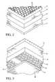
- FIG. 1is a top perspective view of a mattress according to the invention
- FIG. 2is a partial exploded top perspective view of the mattress of FIG. 1 ;
- FIG. 3is a partial exploded bottom perspective view of the mattress of FIG. 1 ;
- FIG. 4is a side elevational view of the mattress of FIG. 1 ;
- FIG. 5is a bottom view of the core layer of the mattress of FIG. 1 ;
- FIG. 6is a bottom view of a core layer of a first alternate embodiment of a mattress according to the invention.
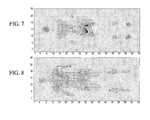
- FIG. 7is a pressure plot showing pressure distribution for an adult female reclining on a typical latex foam medical mattress.
- FIG. 8is a pressure plot showing pressure distribution for an adult female reclining on the mattress of FIG. 1 .
- Bedding mattresses and the components used to make such mattressesmay be characterized by several physical properties, including density, stiffness, tensile strength, indentation force deflection (IFD), hysteresis, and pressure reduction, among others.
- Foams, such as polyurethane foamsmay be further characterized by air permeability.
- Densityis the mass per unit volume.
- Tensile strengthis a measure of the force required to rupture a material when it is stretched. Changes in length after applying a tensile force are measured as elongation percent. Tensile strength and elongation are determined in accordance with the procedures set out in ASTM D 3574. The foam is die cut to form a test specimen with a length of 5.5′′, width of 1′′ and a narrowed central portion with a width of about 0.5′′. The specimen is pulled at both ends until rupture. The tensile strength is calculated by dividing the breaking force by the original cross-sectional area of the central portion of the specimen. Tensile strength is reported in pounds per square inch. The elongation is determined in percent by dividing the difference of the specimen length at rupture and the original specimen length by the original specimen length.
- Stiffnessis the resistance against pressure.
- Indentation Force Deflectionis a measure of the stiffness of the foam and is reported in pounds of force. It represents the force exerted when the foam is compressed by 25% with a compression platen. The procedure is set out in ASTM D 3574. In this case, for IFD at 25%, foam is compressed by 25% of its original height and the force is reported after one minute. The foam samples are cut to a size of 15′′ ⁇ 15′′ ⁇ 4′′ prior to testing.
- Tear strengthis determined using the ASTM D 3574 test procedure. A 6′′ long, 1′′ wide and 1′′ thick foam specimen has a slit formed in one end. The specimen is pulled apart at the slit until it ruptures or at least 50 mm in length is torn. The tear strength is calculated from the maximum force registered on the testing machine divided by the specimen thickness. Tear strength is reported in pounds per linear inch.
- Resilience or elasticityis measured using the ASTM D 3574 standard. Resilience is measured by the ball rebound test, where a steel ball is dropped from a height onto a foam and the rebound distance of the ball is measured as a percentage of a predetermined height.
- Compression modulus or sag factoris a compression measurement defined in the ASTM D 3574 standard.
- the sag factoris defined as the ratio of indentation force deflection at 65% to the indentation force deflection at 25% (IFD 65% to IFD 25% ).
- the sag factoris intended to correlate with a person's perception as to whether a mattress has a combined initial softness and sufficient body support.
- Hysteresis lossis measured using the load deformation curve of the load surface.
- the hysteresis loss curveis determined by loading and de-loading a material.
- the hysteresiswhich is a strong function of the deformation rate, provides a measure of the energy absorbing nature of the material. Foams that are more energy absorbing will have higher hysteresis loss percentages.
- a method for measuring hysteresis lossis outlined in ASTM D 3574.
- Air permeability for foamsis determined in cubic feet per square foot per minute for each foam sample using a Frazier Differential Pressure Air Permeability Pressure machine in accordance with ASTM 737. Higher Frazier permeability values translate to less resistance to air flow.
- Viscoelastic foamsare widely used in the construction of bedding, particularly mattresses and mattress toppers or pads. Bedding constructions that include viscoelastic foams have become very popular not only for medical and orthopedic applications, but also for home use. Viscoelastic foams exhibit slower recovery when a compression force is released than other resilient polyurethane foams. For example, after being released from compression, a resilient polyurethane foam at room temperature and atmospheric conditions generally recovers to its full uncompressed height or thickness in one second or less. By contrast, a viscoelastic foam of the same density and thickness, and at the same room temperature condition, will take significantly longer to recover, even from two to sixty seconds. The recovery time of viscoelastic foams is sensitive to temperature changes within a range close to standard room temperature. Slow recovery foams also exhibit ball rebound values of generally less than about 20% as compared to about 40% or more for other foams.
- viscoelastic foamA precise definition of viscoelastic foam is derived by a dynamic mechanical analysis to measure the glass transition temperature (Tg) of the foam.
- Nonviscoelastic resilient polyurethane foamsbased on a 3000 molecular weight polyether triol, generally have glass transition temperatures below ⁇ 30 C, and possibly even below ⁇ 50 C.
- FIGS. 1-3perspective views of an embodiment of a mattress 10 is shown.
- the mattress 10has a top layer 12 , a core or middle layer 14 , and a bottom layer 16 .
- the three layers 12 , 14 , 16form in combination the sleeping mattress 10 .
- the three layers 12 , 14 , 16may be enveloped with a fabric casing or ticking 18 to form the sleeping mattress 10 .
- Representative fabric casing or ticking materialsinclude: bilaminate nylon knit/polyurethane film, nylon taffeta, polyurethane film, bilaminate polyurethane film, polyester, and others.
- the top layer 12 of this first embodimentcomprises a viscoelastic foam.
- Representative viscoelastic foamsinclude foams with glass transition temperatures above ⁇ 20 C and with ball rebound values of less than approximately 20%.
- the viscoelastic foam of the top layer 12may have a density in the range of 1.5 pcf to 10.0 pcf, more particularly 3.0 pcf to 6.0 pcf.
- Viscoelastic or slow-recovery foamsfrequently have lower air permeabilities, which leads to increased heat build-up when such foams are used in mattress constructions. Higher skin temperatures may accelerate pressure ulcer formation.
- the viscoelastic foam used for the top layer 12is an open cell foam with an air permeability of at least about 60 ft 3 /ft 2 /min, preferably at least about 100 ft 3 /ft 2 /min. Foams with such air permeability help to maintain a reclining person's skin temperature closer to normal body temperatures, e.g., 96-100° F.
- the top surface of the top layer 12preferably has one or more regions with surface modification forming upstanding peaks or projections 20 separated by troughs.
- the top layer 12may be provided with a desired thickness. Particularly, if the top layer 12 has a thickness of about 2 inches, the peaks or projections 20 preferably have substantially flat top surfaces and have a height in the range of about 0.125 to about 1 inch. The peaks or projections 20 are compressible individually thus exhibiting individual spring-like action.
- the peaks or projections 20have hexagonal-shaped top surfaces.
- Other shapesmay be formed as the top surfaces as desired.
- Representative shapesinclude geometric shapes such as but not limited to, circular, oval, triangular, square, diamond, pentagonal, hexagonal, and octagonal.
- the bottom surface 22 of the top layer 12is generally flat or substantially planar.
- the bottom surface 22may be joined, such as with adhesive lamination, to the adjoining surface of the core or middle layer 14 .
- the core layer or middle layer 14 of this first embodimentcomprises a foam, more particularly a polyurethane foam.
- Representative polyurethane foamsinclude conventional polyether foams as well as high resiliency polyether foams.
- High resiliency polyether foamsgenerally have sag factors at least approximately 10% higher than conventional polyether foams.
- the polyurethane foam of the core layer 14may have a density in the range of 1.0 pcf to 6.0 pcf, more particularly 1.5 pcf to 3.0 pcf.
- the top surface 24 of the core layer 14is generally flat or substantially planar.
- the top surface 24may be joined, such as with adhesive lamination, to the adjoining surface of the top layer 12 .
- the bottom surface 26 of the core layer 14is generally flat or substantially planar. As shown in FIG. 3 , the bottom surface 26 has regions from which foam material has been extracted to form multiple cavities 50 separated by upstanding sidewalls 52 . The foam material has not been cut away at the upstanding sidewalls 52 .
- the cavities 50extend to a depth within the thickness of the core layer 14 and terminate in cavity bases 54 .
- the core layer 14may be provided with a desired thickness. Particularly, if the core layer 14 has a thickness of about 3 inches, the cavities 50 extend to depths of from about 0.25 to 2.6 inches.
- the cavities in a regionmay have the same or different depths. Alternatively, the cavities in one region may have a depth different from the cavities of a second region. For simplicity and cost saving, it may be preferred to extract foam to the same cavity depth in each region.
- the open cavities 50define hexagons in cross section, and the upstanding sidewalls 52 form a honey-comb grid or network.
- Other cavity shapesmay be formed as desired. Representative shapes include geometric shapes, such as, but not limited to, circular, oval, triangular, square, diamond, pentagonal, hexagonal, and octagonal.
- One cutting method that may be employed to extract foam from the surface of the core layer 14is a rotary cutting method such as that set out in U.S. Pat. No. 5,534,208, the disclosure of which is incorporated herein by reference.
- FIGS. 4 and 5show in particular that the bottom surface 26 of the core layer 14 in this embodiment defines, four regions from which foam material has been extracted, separated by three regions where foam material remains in tact.
- a first region 28is disposed at one end of the core layer 14 , and rests below a head-supporting region of the mattress 10 .
- a second region 30is disposed adjacent to the first region 28 and rests below a neck-supporting region of the mattress 10 .
- a third region 32is disposed adjacent to the second region 30 and rests below a shoulder- and torso-supporting region of the mattress 10 .
- a fourth region 34is disposed adjacent to the third region 32 and rests below a waist-supporting region of the mattress 10 .
- a fifth region 36is disposed adjacent to the fourth region 34 and rests below a hip- and sacrum-supporting region of the mattress 10 .
- a sixth region 38is disposed adjacent to the fifth region 36 and rests below a leg-supporting region of the mattress 10 .
- a seventh region 40is disposed at the opposite end from the first region 28 , and is adjacent to the sixth region 38 , and rests below a foot/heel-supporting region of the mattress 10 .
- the mattress 10 of this embodimenthas seven zones.
- regions 28 , 32 , 36 , and 40By forming cavities 50 in regions 28 , 32 , 36 , and 40 , such regions have lower support characteristics than present in the regions 30 , 34 , 38 from which foam has not been extracted. As such, heavier body portions of the person reclining on the mattress 10 will sink further into the mattress at the mattress regions corresponding to core layer regions 28 , 32 , 36 and 40 . In other words, the head, shoulders, sacrum and feet of the person reclining on the mattress 10 will sink further into the mattress. This effect redistributes weight/pressure across the mattress surface to reduce ischemic pressure on the person's bony protuberances, but increases the weight/pressure supported by other regions of the mattress where ischemic pressure normally remains well below the ischemic pressure threshold.
- top layer 12 of viscoelastic foam and core layer 14 of foam with regions having foam extracted from a bottom surface to form cavities 50enhances pressure redistribution for a reclining adult.
- the core layer 14is directed with the open cavities 50 directed away from the body-supporting surface of the mattress 10 . In this orientation, the core layer 14 helps to redistribute pressure by permitting heavy or bony body parts to sink into the mattress 10 without bottoming out.
- the bottom surface 26compresses against the top surface 44 of the bottom layer 16 and forms a spring effect that helps support heavier body parts.
- the cavities 50have bases 54 with concavely curved surfaces.
- the concavely curved surfaces of the core layer 14are directed away from the body-supporting surface of the mattress 10 as shown in FIG. 4 . This orientation offers higher initial support, and resists compression to a greater degree than if the core layer 14 were positioned with the cavities 50 directed toward the body-supporting surface of the mattress 10 .
- first region 28a range of 5% to 70% of the foam material volume has been extracted, more particularly 40% to 50%, to form the cavities 50 .
- third region 32a range of 5% to 70% of the foam material volume has been extracted, more particularly 40% to 50%, to form the cavities 50 .
- fifth region 36a range of 5% to 70% of the foam material volume has been extracted, more particularly 40% to 50%, to form the cavities 50 .
- seventh region 40a range of 5% to 70% of the foam material volume has been extracted, more particularly 40% to 50%, to form the cavities 50 .
- the core layer 14altogether has a void volume representing from about 5% to 50% of the core layer 14 material.
- the bottom layer 16 of this first embodimentcomprises a polyurethane foam that includes either a conventional polyether foam or a high resiliency polyether foam having a density in the range of 1.0 pcf to 6.0 pcf, more particularly 1.5 pcf to 3.0 pcf.
- the bottom layer 16has a generally flat or substantially planar top surface 44 that is joined, such as with adhesive lamination, to the bottom surface 26 of the core layer 14 .
- the bottom layer 16also has a generally flat or substantially planar bottom surface 46 .
- FIG. 6shows a bottom surface 126 of an alternative core layer 114 of a mattress construction according to the invention.
- the alternative core layer 114 shown in FIG. 6has cavities 150 formed in four regions 128 , 132 , 136 and 140 , leaving three regions 130 , 134 , and 138 from which foam material has not been extracted.
- the cavities 150 in the core layer 114 of FIG. 6have circular or generally circular shapes in cross section, rather than the hexagonal cavities 50 of the core layer in FIG. 5 . Cavity 150 diameter and depth may vary between cut regions, or between cavities within a region.
- each cavitygenerally may be concavely curved, and the core layer 114 is positioned with the open cavities 150 oriented away from the body supporting surface of the mattress (same orientation as in FIG. 4 ). Where the upstanding sidewalls 152 between cavities 150 are thicker, the region will have a greater resistance to compression than where the upstanding sidewalls 152 between cavities 150 are thinner.
- the core layer 114permits heavier body portions to sink more deeply into the mattress construction than other body portions to redistribute pressure over the mattress surface.
- first region 128 of core layer 114a range of 5% to 65% of the foam material volume has been extracted, more particularly 35% to 45%, to form the cavities 150 .
- third region 132a range of 5% to 65% of the foam material volume has been extracted, more particularly 35% to 45%, to form the cavities 150 .
- fifth region 136a range of 5% to 65% of the foam material volume has been extracted, more particularly 35% to 45%, to form the cavities 150 .
- seventh region 140a range of 5% to 65% of the foam material volume has been extracted, more particularly 35% to 45%, to form the cavities 150 .
- the core layer 114altogether has a void volume representing from about 5% to 45% of the core layer 114 material.
- the mattress 10 or 110is suitable to support heavy-weight persons without springs, wires or other added weight bearing or weight distributing structures.
- pressure distribution mapswere generated using an XSensor PX100: 26.64.01 pressure mapping system comparing the surface pressure on the surface of a commercial medical mattress made from a latex foam (FIG. 7 ), with the surface pressure on the surface of a mattress 10 according to the invention ( FIG. 8 ).
- An adult female with a height 5′3′′ and weighing 120 poundswas pressure mapped in the supine position using an XSensor PX100: 26.64.01 pressure mapping system.
- the subjectwas mapped for 3 minutes at a rate of 600 frames per minute.
- the average pressure for all frameswas added and divided by the total number of frames.
- the peak pressure for all frameswas added and divided by the total number of frames.
- the area for all frameswas added and divided by the total number of frames.
- the average pressure, peak pressure, and areawere reported.
- FIG. 7shows darker regions where pressure was highest, and above the ischemic pressure threshold.
- the mattress 10 according to the invention( FIG. 8 ) redistributed pressure across a greater extent of the body, thus reducing the maximum pressure of the pressure points formed under the head, shoulders, hips and heels to levels below the ischemic pressure threshold.
- Example 1compares the performance of exemplary mattresses (Examples 1 and 2) according to embodiments of the invention with commercial medical mattresses (Samples A, B, C, D and E).
- Example 1was a three layer foam mattress 10 with the first layer 12 composed of a viscoelastic polyurethane foam with a density of 5 pcf and a thickness of about 2 inches, the core layer 14 composed of a conventional polyether polyurethane foam with a density of 1.65 pcf and thickness of about 3 inches, and the bottom layer 16 composed of a conventional polyether polyurethane foam with a density of 1.8 pcf and thickness of about 1 inch.
- the top surface of the top layer 12preferably has surface modifications forming upstanding peaks or projections 20 separated by troughs.
- the projections 20are hexagonal in shape with substantially flat top surfaces and have a height in the range of about 0.375 inches.
- the core layer 14had a thickness of 3 inches with cavity depth of 2 inches.
- the cavities 50had hexagonal cross-sectional shapes, with each side of the hexagon having a length of approximately 1 inch. Four of the zones in the seven total zones had cavities in the core layer, with the cavity depth approximately equal in all four zones.
- Example 2was a three layer foam mattress with the first layer composed of a viscoelastic polyurethane foam with a density of 4 pcf, and thickness of about 2 inches, an alternative core layer 114 composed of a conventional polyether polyurethane foam with a density of 1.75 pcf and thickness of about 2 inches and the bottom layer composed of a conventional polyether polyurethane foam with a density of 1.8 pcf and thickness of about 2 inches.
- the top surface of the top layerpreferably has surface modifications forming upstanding peaks or projections separated by troughs. The projections are hexagonal in shape with substantially flat top surfaces and have a height in the range of about 0.625 inches.
- the core layer 114had a thickness of 2 inches with cavity depth of 1 inch.
- the cavities 150had circular cross-sectional shapes with a diameter of 1.75 inches. Four of the zones in the seven total zones had cavities in the core layer, with the cavity depth approximately equal in all four zones.
- Sample Awas a commercially available bedding mattress with a 6 inch thickness composed of three layers of foam.
- the first or top layeris a high resiliency polyether polyurethane foam with a thickness of about 2 inches and pin convolutions in the heel section, and two core layers are of conventional polyether polyurethane foam, each with a thickness of about 2 inches.
- Sample Bwas a commercially available bedding mattress with a 6 inch thickness composed of two 3 inch wide side rails and a 30 inch wide center section.
- the center sectionis composed of two layers of polyurethane foam.
- the first or top layeris a viscoelastic polyurethane foam with a thickness of about 3 inches with a softer viscoelastic polyurethane foam in the heel section that slopes to the end of the mattress, and a core layer of conventional polyether polyurethane foam with a thickness of about 3 inches.
- Sample Cwas a commercially available medical mattress with a single layer of a conventional polyether polyurethane foam with a thickness of about 6.5 inches.
- Sample Dwas a commercially available medical mattress having four layers and a thickness of 7 inches.
- the first layeris composed of a high density polyether polyurethane foam with a contour cut surface and a thickness of about 2 inches that slopes down to the end of the heel section.
- the second layeris a conventional polyether polyurethane foam with a thickness of about 2 inches.
- the third and fourth layersare conventional polyether polyurethane foams with thicknesses of about 1.5 inches.
- Sample Ewas a commercially available medical mattress that is formed as a single layer of a latex foam with a thickness of about 4 inches.
- a Pressure map generated for Sample Eis shown in FIG. 8 .
- Table 1The data in Table 1 was generated from pressure distribution maps using an XSensor PX100: 26.64.01 pressure mapping system. An adult female with a height of 5′3′′ and weighing 120 pounds reclined in the supine position on each mattress. The pressure resulting from supporting the reclining female was mapped for 3 minutes at a rate of 600 frames per minute. The average pressure for all frames was added and divided by the total number of frames. The peak pressure for all frames was added and divided by the total number of frames. The area for all frames was added and divided by the total number of frames. The average pressure, peak pressure, and area were reported.
Landscapes
- Mattresses And Other Support Structures For Chairs And Beds (AREA)
- Invalid Beds And Related Equipment (AREA)
Abstract
Description
| TABLE 1 | ||||||
| Avg. | Max. | Avg. | ||||
| Mattress | Rating | Pressure | Pressure | Area | ||
| Example 1 - 7 Zone | 14.3 | 29.9 | 664 | |||
| Example 2 - 7 zone | 18.1 | 33.9 | 447 | |||
| Sample A | 300 lbs. | 17.2 | 58.9 | 434 | ||
| Sample B | 500 lbs. | 16.0 | 45.5 | 451 | ||
| Sample C | 750 lbs. | 23.4 | 49.1 | 320 | ||
| Sample D | 750 lbs. | 18.9 | 46.9 | 374 | ||
| Sample E | 20.2 | 50.8 | 370 | |||
Claims (18)
Priority Applications (2)
| Application Number | Priority Date | Filing Date | Title |
|---|---|---|---|
| US12/429,778US7886388B2 (en) | 2009-04-24 | 2009-04-24 | Mattress adapted for supporting heavy weight persons |
| US13/026,422US8359689B2 (en) | 2009-04-24 | 2011-02-14 | Mattress adapted for supporting heavy weight persons |
Applications Claiming Priority (1)
| Application Number | Priority Date | Filing Date | Title |
|---|---|---|---|
| US12/429,778US7886388B2 (en) | 2009-04-24 | 2009-04-24 | Mattress adapted for supporting heavy weight persons |
Related Child Applications (1)
| Application Number | Title | Priority Date | Filing Date |
|---|---|---|---|
| US13/026,422Continuation-In-PartUS8359689B2 (en) | 2009-04-24 | 2011-02-14 | Mattress adapted for supporting heavy weight persons |
Publications (2)
| Publication Number | Publication Date |
|---|---|
| US20100269262A1 US20100269262A1 (en) | 2010-10-28 |
| US7886388B2true US7886388B2 (en) | 2011-02-15 |
Family
ID=42990755
Family Applications (1)
| Application Number | Title | Priority Date | Filing Date |
|---|---|---|---|
| US12/429,778ActiveUS7886388B2 (en) | 2009-04-24 | 2009-04-24 | Mattress adapted for supporting heavy weight persons |
Country Status (1)
| Country | Link |
|---|---|
| US (1) | US7886388B2 (en) |
Cited By (8)
| Publication number | Priority date | Publication date | Assignee | Title |
|---|---|---|---|---|
| US20110061168A1 (en)* | 2009-09-12 | 2011-03-17 | David Farley | Sleep support surface that includes a layer with large diameter cleaving |
| US20130269113A1 (en)* | 2012-04-16 | 2013-10-17 | Robert Wood | Composite flexible frame mattress |
| US8793821B2 (en) | 2010-07-12 | 2014-08-05 | Doug Fowkes | Cushion with double stacked off-set honeycomb |
| US20150040327A1 (en)* | 2011-09-15 | 2015-02-12 | Tempur-Pedic Management, Llc | Body support modified with viscous gel and method of manufacturing a body support using the same |
| USD738644S1 (en) | 2013-09-20 | 2015-09-15 | Future Foam, Inc. | Pillow |
| WO2019136781A1 (en)* | 2018-01-15 | 2019-07-18 | 四川大学 | 3d printing method for shock-absorption sole and insole of negative poisson ratio structure |
| US10827845B2 (en) | 2017-02-24 | 2020-11-10 | Sealy Technology, Llc | Support cushions including a support insert with a bag for directing air flow, and methods for controlling surface temperature of same |
| US11160386B2 (en) | 2018-06-29 | 2021-11-02 | Tempur World, Llc | Body support cushion with ventilation system |
Families Citing this family (17)
| Publication number | Priority date | Publication date | Assignee | Title |
|---|---|---|---|---|
| JP4293281B1 (en)* | 2007-07-23 | 2009-07-08 | 株式会社ブリヂストン | Vehicle seat pad and vehicle seat |
| AU326702S (en)* | 2009-06-09 | 2009-07-09 | Mantzis Holdings Pty Ltd | Mattress core |
| US9380882B2 (en) | 2012-09-20 | 2016-07-05 | Kickball Concepts, Llc | Mattress with user adjustable comfort features |
| USD725408S1 (en)* | 2014-04-04 | 2015-03-31 | Joinwin Technology Co., Ltd. | Mattress |
| US9888785B2 (en) | 2014-04-21 | 2018-02-13 | Casper Sleep Inc. | Mattress |
| US9962009B2 (en) | 2014-04-21 | 2018-05-08 | Casper Sleep Inc. | Mattress |
| USD822409S1 (en) | 2015-11-16 | 2018-07-10 | Casper Sleep Inc. | Pillow set |
| US10736300B2 (en) | 2016-08-16 | 2020-08-11 | Casper Sleep Inc. | Dog mattress |
| US10541172B2 (en) | 2016-08-24 | 2020-01-21 | International Business Machines Corporation | Semiconductor device with reduced contact resistance |
| US11116326B2 (en) | 2017-08-14 | 2021-09-14 | Casper Sleep Inc. | Mattress containing ergonomic and firmness-regulating endoskeleton |
| KR20200112869A (en) | 2018-01-08 | 2020-10-05 | 캐스퍼 슬립 인크. | Interactive portable lighting system |
| USD862104S1 (en) | 2018-03-21 | 2019-10-08 | Casper Sleep Inc. | Platform bed frame |
| WO2019209733A1 (en) | 2018-04-23 | 2019-10-31 | Casper Sleep Inc. | Temperature-regulating mattress |
| USD885640S1 (en) | 2018-10-23 | 2020-05-26 | Casper Sleep Inc. | Lamp assembly |
| USD908398S1 (en) | 2019-08-27 | 2021-01-26 | Casper Sleep Inc. | Mattress |
| USD921531S1 (en) | 2019-09-10 | 2021-06-08 | Casper Sleep Inc. | Zipper |
| USD927889S1 (en) | 2019-10-16 | 2021-08-17 | Casper Sleep Inc. | Mattress layer |
Citations (41)
| Publication number | Priority date | Publication date | Assignee | Title |
|---|---|---|---|---|
| US3828378A (en) | 1972-07-31 | 1974-08-13 | Johnson & Johnson | Support means for the even distribution of body pressure |
| US3885257A (en) | 1972-10-30 | 1975-05-27 | Evans Ronald J P | Pressure controlled resilient supporting structure |
| GB1445561A (en) | 1972-04-24 | 1976-08-11 | Watkin B C | Mattresses |
| US4073020A (en) | 1976-04-19 | 1978-02-14 | The Goodyear Tire & Rubber Company | Contoured foam mattress |
| US4265484A (en) | 1979-05-10 | 1981-05-05 | The Goodyear Tire & Rubber Company | Reinforced foamed body support member |
| FR2473291A1 (en) | 1980-01-09 | 1981-07-17 | Pirelli France | composite cellular mattress - with zones of varying compressive stiffness, by incorporation of cavities of varying size or proximity |
| USD263104S (en) | 1977-09-22 | 1982-02-23 | The Goodyear Tire & Rubber Company | Foam mattress core |
| US4335476A (en) | 1979-03-08 | 1982-06-22 | Watkin Bernard C | Mattress |
| US4706313A (en) | 1986-05-01 | 1987-11-17 | Comfortex, Inc. | Decubitus ulcer mattress |
| US4757564A (en) | 1986-08-25 | 1988-07-19 | American-National Watermattress Corporation | Mattress having cover with memory fabric |
| US4879776A (en) | 1988-04-04 | 1989-11-14 | Farley David L | Anatomically conformable foam support pad |
| US5111542A (en) | 1988-04-04 | 1992-05-12 | Farley David L | Anatomically conformable foam support pad |
| US5127119A (en) | 1990-10-29 | 1992-07-07 | Rogers John E | Shear stress control in body support pads |
| US5201780A (en) | 1991-09-06 | 1993-04-13 | Jay Medical, Ltd. | Anti-decubitus mattress pad |
| US5231717A (en) | 1989-08-23 | 1993-08-03 | Leggett & Platt, Incorporated | Bedding system |
| US5334646A (en) | 1977-03-17 | 1994-08-02 | Applied Elastomerics, Inc. | Thermoplastic elastomer gelatinous articles |
| USD352858S (en) | 1993-05-10 | 1994-11-29 | Farley David L | Anatomically conformable support pad |
| EP0634124A1 (en) | 1993-07-15 | 1995-01-18 | Diamona Hermann Koch GmbH & Co. KG, Fabrik für Wohn- und Schlafkomfort | Mattress |
| US5430901A (en) | 1993-06-10 | 1995-07-11 | Farley; David L. | Anatomically conformable therapeutic mattress overlay |
| NL1000224C2 (en) | 1995-04-25 | 1996-10-28 | Recticel Nederland Bv | Curved profile cutting in foam cushion base |
| US5655241A (en) | 1989-08-23 | 1997-08-12 | L&P Property Management Company | Sleep enhancing posturized mattress and mattress cover assembly |
| USD383349S (en) | 1996-07-12 | 1997-09-09 | Carpenter Company | Cushion pad |
| US5749111A (en) | 1996-02-14 | 1998-05-12 | Teksource, Lc | Gelatinous cushions with buckling columns |
| US5794289A (en) | 1995-10-06 | 1998-08-18 | Gaymar Industries, Inc. | Mattress for relieving pressure ulcers |
| EP0870447A2 (en) | 1997-04-10 | 1998-10-14 | Lück GmbH & Co. KG | Upholstery made of foam material |
| US5879780A (en) | 1996-09-20 | 1999-03-09 | Hexcel Corporation | Lightweight self-sustaining anisotropic honeycomb material |
| US5974609A (en) | 1998-06-29 | 1999-11-02 | The Spring Air Company | Quilt top mattress with convoluted foam cushion |
| US6041459A (en) | 1997-10-03 | 2000-03-28 | The Spring Air Company | Convoluted foam cushion |
| US6237173B1 (en)* | 1999-03-15 | 2001-05-29 | August Lotz Co., Inc. | Articulated foam futon mattress |
| US20020046800A1 (en) | 1999-10-01 | 2002-04-25 | Polymer Group Inc. | Nonwoven fabric exhibiting cross-direction extensibility and recovery |
| US6701557B2 (en) | 2001-11-29 | 2004-03-09 | Sealy Technology Llc | Single piece foam toppers with perimeter areas having variable support and firmness properties |
| US6807698B2 (en) | 2002-06-01 | 2004-10-26 | Sleepadvantage, Llc | Bed having low body pressure and alignment |
| JP2005118097A (en) | 2003-10-14 | 2005-05-12 | Hunet:Kk | Body pressure dispersing mattress |
| US20050172414A1 (en) | 2003-09-03 | 2005-08-11 | Lewis Jan A. | Pressure relieving mattress |
| US7036172B2 (en) | 2002-06-01 | 2006-05-02 | Sleepadvantage, Lc | Bed having low body pressure and alignment |
| US20060288491A1 (en)* | 2005-06-24 | 2006-12-28 | Mikkelsen Tom D | Reticulated material body support and method |
| WO2007000581A1 (en) | 2005-06-29 | 2007-01-04 | Seating Design & Development Limited | A therapeutic mattress |
| WO2007053035A1 (en) | 2005-10-31 | 2007-05-10 | Ekornes Asa | Padding for furniture |
| US20080028532A1 (en) | 2003-09-18 | 2008-02-07 | Rogers John E | Mattress and method for reducing stress concentration when supporting a body |
| WO2008086861A1 (en) | 2007-01-15 | 2008-07-24 | Recticel Schlafkomfort Gmbh | Mattress |
| JP2008258354A (en) | 2007-04-04 | 2008-10-23 | Matsushita Electric Ind Co Ltd | Semiconductor device and manufacturing method thereof |
- 2009
- 2009-04-24USUS12/429,778patent/US7886388B2/enactiveActive
Patent Citations (51)
| Publication number | Priority date | Publication date | Assignee | Title |
|---|---|---|---|---|
| GB1445561A (en) | 1972-04-24 | 1976-08-11 | Watkin B C | Mattresses |
| US3828378A (en) | 1972-07-31 | 1974-08-13 | Johnson & Johnson | Support means for the even distribution of body pressure |
| US3885257A (en) | 1972-10-30 | 1975-05-27 | Evans Ronald J P | Pressure controlled resilient supporting structure |
| US4073020A (en) | 1976-04-19 | 1978-02-14 | The Goodyear Tire & Rubber Company | Contoured foam mattress |
| US4148855A (en) | 1976-04-19 | 1979-04-10 | The Goodyear Tire & Rubber Company | Method of molding a foamed mattress having a crown area with cored-out areas |
| US5334646A (en) | 1977-03-17 | 1994-08-02 | Applied Elastomerics, Inc. | Thermoplastic elastomer gelatinous articles |
| US5334646B1 (en) | 1977-03-17 | 1998-09-08 | Applied Elastomerics Inc | Thermoplastic elastomer gelatinous articles |
| USD263104S (en) | 1977-09-22 | 1982-02-23 | The Goodyear Tire & Rubber Company | Foam mattress core |
| US4335476A (en) | 1979-03-08 | 1982-06-22 | Watkin Bernard C | Mattress |
| US4265484A (en) | 1979-05-10 | 1981-05-05 | The Goodyear Tire & Rubber Company | Reinforced foamed body support member |
| FR2473291A1 (en) | 1980-01-09 | 1981-07-17 | Pirelli France | composite cellular mattress - with zones of varying compressive stiffness, by incorporation of cavities of varying size or proximity |
| US4706313A (en) | 1986-05-01 | 1987-11-17 | Comfortex, Inc. | Decubitus ulcer mattress |
| US4757564A (en) | 1986-08-25 | 1988-07-19 | American-National Watermattress Corporation | Mattress having cover with memory fabric |
| US5010609A (en) | 1988-04-04 | 1991-04-30 | Farley David L | Anatomically conformable foam support pad |
| US5038433A (en) | 1988-04-04 | 1991-08-13 | Farley David L | Anatomically conformable foam support pad |
| US5111542A (en) | 1988-04-04 | 1992-05-12 | Farley David L | Anatomically conformable foam support pad |
| US5178811A (en) | 1988-04-04 | 1993-01-12 | Farley David L | Method of forming an anatomically conformable foam support pad |
| US4879776A (en) | 1988-04-04 | 1989-11-14 | Farley David L | Anatomically conformable foam support pad |
| US5077849A (en) | 1988-04-04 | 1992-01-07 | Farley David L | Anatomically conformable foam support pad |
| US5231717A (en) | 1989-08-23 | 1993-08-03 | Leggett & Platt, Incorporated | Bedding system |
| US5655241A (en) | 1989-08-23 | 1997-08-12 | L&P Property Management Company | Sleep enhancing posturized mattress and mattress cover assembly |
| US5127119A (en) | 1990-10-29 | 1992-07-07 | Rogers John E | Shear stress control in body support pads |
| US5255404A (en) | 1991-09-06 | 1993-10-26 | Jay Medical, Ltd. | Anti-decubitus mattress pad |
| US5303436A (en) | 1991-09-06 | 1994-04-19 | Jay Medical, Ltd. | Anti-decubing mattress pad |
| US5201780A (en) | 1991-09-06 | 1993-04-13 | Jay Medical, Ltd. | Anti-decubitus mattress pad |
| US5511260A (en) | 1991-09-06 | 1996-04-30 | Rik Medical | Anti-decubitus mattress pad |
| USD352858S (en) | 1993-05-10 | 1994-11-29 | Farley David L | Anatomically conformable support pad |
| US5430901A (en) | 1993-06-10 | 1995-07-11 | Farley; David L. | Anatomically conformable therapeutic mattress overlay |
| EP0634124A1 (en) | 1993-07-15 | 1995-01-18 | Diamona Hermann Koch GmbH & Co. KG, Fabrik für Wohn- und Schlafkomfort | Mattress |
| NL1000224C2 (en) | 1995-04-25 | 1996-10-28 | Recticel Nederland Bv | Curved profile cutting in foam cushion base |
| US5794289A (en) | 1995-10-06 | 1998-08-18 | Gaymar Industries, Inc. | Mattress for relieving pressure ulcers |
| US7076822B2 (en) | 1996-02-14 | 2006-07-18 | Edizone, Lc | Stacked cushions |
| US5749111A (en) | 1996-02-14 | 1998-05-12 | Teksource, Lc | Gelatinous cushions with buckling columns |
| USD383349S (en) | 1996-07-12 | 1997-09-09 | Carpenter Company | Cushion pad |
| US5879780A (en) | 1996-09-20 | 1999-03-09 | Hexcel Corporation | Lightweight self-sustaining anisotropic honeycomb material |
| EP0870447A2 (en) | 1997-04-10 | 1998-10-14 | Lück GmbH & Co. KG | Upholstery made of foam material |
| US6041459A (en) | 1997-10-03 | 2000-03-28 | The Spring Air Company | Convoluted foam cushion |
| US5974609A (en) | 1998-06-29 | 1999-11-02 | The Spring Air Company | Quilt top mattress with convoluted foam cushion |
| US6237173B1 (en)* | 1999-03-15 | 2001-05-29 | August Lotz Co., Inc. | Articulated foam futon mattress |
| US20020046800A1 (en) | 1999-10-01 | 2002-04-25 | Polymer Group Inc. | Nonwoven fabric exhibiting cross-direction extensibility and recovery |
| US6701557B2 (en) | 2001-11-29 | 2004-03-09 | Sealy Technology Llc | Single piece foam toppers with perimeter areas having variable support and firmness properties |
| US6807698B2 (en) | 2002-06-01 | 2004-10-26 | Sleepadvantage, Llc | Bed having low body pressure and alignment |
| US7036172B2 (en) | 2002-06-01 | 2006-05-02 | Sleepadvantage, Lc | Bed having low body pressure and alignment |
| US20050172414A1 (en) | 2003-09-03 | 2005-08-11 | Lewis Jan A. | Pressure relieving mattress |
| US20080028532A1 (en) | 2003-09-18 | 2008-02-07 | Rogers John E | Mattress and method for reducing stress concentration when supporting a body |
| JP2005118097A (en) | 2003-10-14 | 2005-05-12 | Hunet:Kk | Body pressure dispersing mattress |
| US20060288491A1 (en)* | 2005-06-24 | 2006-12-28 | Mikkelsen Tom D | Reticulated material body support and method |
| WO2007000581A1 (en) | 2005-06-29 | 2007-01-04 | Seating Design & Development Limited | A therapeutic mattress |
| WO2007053035A1 (en) | 2005-10-31 | 2007-05-10 | Ekornes Asa | Padding for furniture |
| WO2008086861A1 (en) | 2007-01-15 | 2008-07-24 | Recticel Schlafkomfort Gmbh | Mattress |
| JP2008258354A (en) | 2007-04-04 | 2008-10-23 | Matsushita Electric Ind Co Ltd | Semiconductor device and manufacturing method thereof |
Cited By (10)
| Publication number | Priority date | Publication date | Assignee | Title |
|---|---|---|---|---|
| US20110061168A1 (en)* | 2009-09-12 | 2011-03-17 | David Farley | Sleep support surface that includes a layer with large diameter cleaving |
| US8621694B2 (en)* | 2009-09-12 | 2014-01-07 | Fxi, Inc. | Sleep support surface that includes a layer with large diameter cleaving |
| US8793821B2 (en) | 2010-07-12 | 2014-08-05 | Doug Fowkes | Cushion with double stacked off-set honeycomb |
| US20150040327A1 (en)* | 2011-09-15 | 2015-02-12 | Tempur-Pedic Management, Llc | Body support modified with viscous gel and method of manufacturing a body support using the same |
| US20130269113A1 (en)* | 2012-04-16 | 2013-10-17 | Robert Wood | Composite flexible frame mattress |
| USD738644S1 (en) | 2013-09-20 | 2015-09-15 | Future Foam, Inc. | Pillow |
| USD751322S1 (en) | 2013-09-20 | 2016-03-15 | Future Foam, Inc. | Pillow |
| US10827845B2 (en) | 2017-02-24 | 2020-11-10 | Sealy Technology, Llc | Support cushions including a support insert with a bag for directing air flow, and methods for controlling surface temperature of same |
| WO2019136781A1 (en)* | 2018-01-15 | 2019-07-18 | 四川大学 | 3d printing method for shock-absorption sole and insole of negative poisson ratio structure |
| US11160386B2 (en) | 2018-06-29 | 2021-11-02 | Tempur World, Llc | Body support cushion with ventilation system |
Also Published As
| Publication number | Publication date |
|---|---|
| US20100269262A1 (en) | 2010-10-28 |
Similar Documents
| Publication | Publication Date | Title |
|---|---|---|
| US7886388B2 (en) | Mattress adapted for supporting heavy weight persons | |
| US8359689B2 (en) | Mattress adapted for supporting heavy weight persons | |
| US8037562B2 (en) | Tension relieving body support apparatus | |
| US6807698B2 (en) | Bed having low body pressure and alignment | |
| US7036172B2 (en) | Bed having low body pressure and alignment | |
| US20050115003A1 (en) | Internal contour foam mattress | |
| US7845035B2 (en) | Pressure dispersion support systems | |
| US10548789B2 (en) | Methods and systems for a dynamic support mattress to treat and reduce the incidence of pressure ulcers | |
| US5134735A (en) | Mattress cushion with multiple zones | |
| US20170325596A1 (en) | Foam mattress having an adjustable mattress core for adjusting and customizing its firmness, assembling method and kit thereof | |
| US5022111A (en) | Pressure reduction mattress | |
| US7254852B2 (en) | Cushioning device | |
| US5077849A (en) | Anatomically conformable foam support pad | |
| US20100325806A1 (en) | Pressure dispersion support systems | |
| US20160296031A1 (en) | Support pillows and mattresses for body alignment | |
| US9770117B1 (en) | Mattress and topper with variable and adjustable deflection areas for ultra-low pressures with postural alignment | |
| US20140283305A1 (en) | Pillow and mattress pad system with variable zones of elasticity | |
| US20080010751A1 (en) | Spinal tension and pressure relieving body support apparatus | |
| US20130000045A1 (en) | Support apparatus with gel layer | |
| US10709256B2 (en) | Efficient mattress having low pressure and alignment | |
| US9615984B2 (en) | Treatment of chronic back pain using a three-dimensional monofilament mattress overlay | |
| KR101864769B1 (en) | Memory foam pillow | |
| KR101922599B1 (en) | Memory foam pillow | |
| US20110083277A1 (en) | Foam pad | |
| JP2002078569A (en) | Body pressure dispersing mattress |
Legal Events
| Date | Code | Title | Description |
|---|---|---|---|
| AS | Assignment | Owner name:FOAMEX L.P., PENNSYLVANIA Free format text:ASSIGNMENT OF ASSIGNORS INTEREST;ASSIGNORS:WARREN, STEPHEN C.;CONTRERAS, JOSE D.;MCCABE, KERRY L.;AND OTHERS;REEL/FRAME:022594/0848 Effective date:20090424 | |
| AS | Assignment | Owner name:WACHOVIA BANK, NATIONAL ASSOCIATION, NEW YORK Free format text:SECURITY AGREEMENT;ASSIGNOR:FOAMEX INNOVATIONS OPERATING COMPANY;REEL/FRAME:023056/0120 Effective date:20090612 | |
| AS | Assignment | Owner name:FOAMEX INNOVATIONS OPERATING COMPANY, PENNSYLVANIA Free format text:ASSIGNMENT OF ASSIGNORS INTEREST;ASSIGNOR:FOAMEX INNOVATIONS, INC. (FORMERLY MP FOAM DIP LLC);REEL/FRAME:023094/0786 Effective date:20090728 | |
| STCF | Information on status: patent grant | Free format text:PATENTED CASE | |
| AS | Assignment | Owner name:FXI, INC., PENNSYLVANIA Free format text:CHANGE OF NAME;ASSIGNOR:FOAMEX INNOVATIONS OPERATING COMPANY;REEL/FRAME:027340/0565 Effective date:20110404 | |
| FPAY | Fee payment | Year of fee payment:4 | |
| AS | Assignment | Owner name:FXI, INC., PENNSYLVANIA Free format text:RELEASE BY SECURED PARTY;ASSIGNOR:WELLS FARGO BANK, NATIONAL ASSOCIATION, SUCCESSOR BY MERGER TO WACHOVIA BANK, NATIONAL ASSOCIATION, AS AGENT;REEL/FRAME:037186/0125 Effective date:20151124 Owner name:SUNTRUST BANK, AS AGENT, GEORGIA Free format text:SECURITY INTEREST;ASSIGNOR:FXI, INC.;REEL/FRAME:037189/0351 Effective date:20151125 | |
| AS | Assignment | Owner name:FXI, INC., PENNSYLVANIA Free format text:RELEASE BY SECURED PARTY;ASSIGNOR:SUNTRUST BANK, AS AGENT;REEL/FRAME:044360/0430 Effective date:20171102 Owner name:SUNTRUST BANK, AS AGENT, GEORGIA Free format text:SECURITY INTEREST;ASSIGNOR:FXI, INC.;REEL/FRAME:044360/0806 Effective date:20171102 Owner name:U.S. BANK NATIONAL ASSOCIATION, GEORGIA Free format text:SECURITY INTEREST;ASSIGNOR:FXI, INC.;REEL/FRAME:044779/0483 Effective date:20171102 | |
| MAFP | Maintenance fee payment | Free format text:PAYMENT OF MAINTENANCE FEE, 8TH YEAR, LARGE ENTITY (ORIGINAL EVENT CODE: M1552) Year of fee payment:8 | |
| AS | Assignment | Owner name:U.S. BANK NATIONAL ASSOCIATION, GEORGIA Free format text:SECURITY INTEREST;ASSIGNORS:FXI, INC.;INNOCOR, INC.;REEL/FRAME:052004/0277 Effective date:20200224 | |
| AS | Assignment | Owner name:TRUIST BANK, AS AGENT, GEORGIA Free format text:SECURITY INTEREST;ASSIGNORS:FXI, INC.;INNOCOR, INC.;REEL/FRAME:052019/0442 Effective date:20200224 Owner name:FXI, INC., PENNSYLVANIA Free format text:RELEASE BY SECURED PARTY;ASSIGNOR:TRUIST BANK, AS AGENT, SUCCESSOR-BY-MERGER TO SUNTRUST BANK;REEL/FRAME:052019/0659 Effective date:20200224 | |
| MAFP | Maintenance fee payment | Free format text:PAYMENT OF MAINTENANCE FEE, 12TH YEAR, LARGE ENTITY (ORIGINAL EVENT CODE: M1553); ENTITY STATUS OF PATENT OWNER: LARGE ENTITY Year of fee payment:12 | |
| AS | Assignment | Owner name:FXI, INC., PENNSYLVANIA Free format text:RELEASE OF SECURITY INTEREST IN PATENTS AT R/F 044779/0483;ASSIGNOR:U.S. BANK TRUST COMPANY, NATIONAL ASSOCIATION, AS AGENT;REEL/FRAME:063500/0738 Effective date:20230501 Owner name:U.S. BANK TRUST COMPANY, NATIONAL ASSOCIATION, AS AGENT, GEORGIA Free format text:SECURITY INTEREST;ASSIGNOR:FXI, INC.;REEL/FRAME:063492/0830 Effective date:20230501 |