US7885706B2 - System and device for seizure detection - Google Patents
System and device for seizure detectionDownload PDFInfo
- Publication number
- US7885706B2 US7885706B2US11/524,160US52416006AUS7885706B2US 7885706 B2US7885706 B2US 7885706B2US 52416006 AUS52416006 AUS 52416006AUS 7885706 B2US7885706 B2US 7885706B2
- Authority
- US
- United States
- Prior art keywords
- eeg
- arrangement
- data
- processing unit
- user
- Prior art date
- Legal status (The legal status is an assumption and is not a legal conclusion. Google has not performed a legal analysis and makes no representation as to the accuracy of the status listed.)
- Expired - Fee Related, expires
Links
Images


Classifications
- A—HUMAN NECESSITIES
- A61—MEDICAL OR VETERINARY SCIENCE; HYGIENE
- A61B—DIAGNOSIS; SURGERY; IDENTIFICATION
- A61B5/00—Measuring for diagnostic purposes; Identification of persons
- A61B5/24—Detecting, measuring or recording bioelectric or biomagnetic signals of the body or parts thereof
- A61B5/25—Bioelectric electrodes therefor
- A61B5/279—Bioelectric electrodes therefor specially adapted for particular uses
- A61B5/291—Bioelectric electrodes therefor specially adapted for particular uses for electroencephalography [EEG]
- A—HUMAN NECESSITIES
- A61—MEDICAL OR VETERINARY SCIENCE; HYGIENE
- A61B—DIAGNOSIS; SURGERY; IDENTIFICATION
- A61B5/00—Measuring for diagnostic purposes; Identification of persons
- A61B5/24—Detecting, measuring or recording bioelectric or biomagnetic signals of the body or parts thereof
- A61B5/30—Input circuits therefor
- A61B5/307—Input circuits therefor specially adapted for particular uses
- A61B5/31—Input circuits therefor specially adapted for particular uses for electroencephalography [EEG]
- A—HUMAN NECESSITIES
- A61—MEDICAL OR VETERINARY SCIENCE; HYGIENE
- A61B—DIAGNOSIS; SURGERY; IDENTIFICATION
- A61B5/00—Measuring for diagnostic purposes; Identification of persons
- A61B5/24—Detecting, measuring or recording bioelectric or biomagnetic signals of the body or parts thereof
- A61B5/316—Modalities, i.e. specific diagnostic methods
- A61B5/369—Electroencephalography [EEG]
- A—HUMAN NECESSITIES
- A61—MEDICAL OR VETERINARY SCIENCE; HYGIENE
- A61B—DIAGNOSIS; SURGERY; IDENTIFICATION
- A61B5/00—Measuring for diagnostic purposes; Identification of persons
- A61B5/40—Detecting, measuring or recording for evaluating the nervous system
- A61B5/4076—Diagnosing or monitoring particular conditions of the nervous system
- A61B5/4094—Diagnosing or monitoring seizure diseases, e.g. epilepsy
- A—HUMAN NECESSITIES
- A61—MEDICAL OR VETERINARY SCIENCE; HYGIENE
- A61B—DIAGNOSIS; SURGERY; IDENTIFICATION
- A61B5/00—Measuring for diagnostic purposes; Identification of persons
- A61B5/68—Arrangements of detecting, measuring or recording means, e.g. sensors, in relation to patient
- A61B5/6801—Arrangements of detecting, measuring or recording means, e.g. sensors, in relation to patient specially adapted to be attached to or worn on the body surface
- A61B5/6813—Specially adapted to be attached to a specific body part
- A61B5/6814—Head
Definitions
- Ambulatory epilepsy diagnosis and monitoring systemshave been developed to capture epileptic events in non-clinical settings and alleviate the costs associated with long-term, in-patient monitoring sessions conducted in hospitals.
- the ambulatory systemconsists of a data acquisition arrangement that captures brain waves of a subject and a video camera mounted on a tripod for capturing video of the subject. The physician may then review the brain waves and the video offline to analyze the subject's activity and any epileptic events that may have occurred during a monitoring period.
- the conventional data acquisition arrangementtends to be bulky and heavy, limiting the subject's range of movement and inhibiting performance of daily tasks. That is, the subject may not be able to cook, clean, do laundry or relax comfortably while tethered to the data acquisition arrangement. Additionally, the video camera is statically positioned and captures only a limited viewing range. If the subject is outside of the viewing range or if the video camera is otherwise non-functional (out of tape, battery dead, etc.), the subject's activity and the epileptic event(s) will not be captured. Thus, the conventional ambulatory systems severely restrict the subject's activity and movement even in non-clinical settings.
- the present inventionrelates to a seizure detector headset comprising a head mounting arrangement sized and shaped to be worn on a user's head and a plurality of electrodes disposed on the arrangement so that, when the arrangement is worn on the user's head, the electrodes contact target portions of a scalp to detect electrical activity of a brain of the user in combination with an image capture device disposed on the arrangement so that, when the arrangement is worn on the user's head, a field of view of the image capture device includes a portion of an anatomy of the user and a processing unit generating EEG data from the electrical activity, wherein, when the EEG data is indicative of an epileptic event, the processing unit activates the image capture device to capture video data of the user.
- FIG. 1shows an exemplary embodiment of a wearable EEG system according to the present invention.
- FIG. 2shows an exemplary embodiment of an architecture of a wearable EEG arrangement according to the present invention.
- FIG. 3 ashows a cross-sectional view of an exemplary embodiment of an EEG electrode unit according to the present invention.
- FIG. 3 bshows an underside view of an exemplary embodiment of an EEG electrode unit according to the present invention.
- FIG. 4shows an exemplary embodiment of video data captured by a wearable EEG arrangement according to the present invention.
- FIG. 5shows an alternative exemplary embodiment of a wearable EEG system according to the present invention.
- FIG. 6 ashows a top view of an exemplary embodiment of an EEG minidisc according to the present invention.
- FIG. 6 bshows a side view of an exemplary embodiment of an EEG minidisc according to the present invention.
- FIG. 6 cshows a bottom view of an exemplary embodiment of an EEG minidisc according to the present invention.
- FIG. 6 dshows a cross-sectional view of an exemplary embodiment of an EEG minidisc according to the present invention.
- FIG. 7shows an exemplary embodiment of an architecture of an EEG minidisc according to the present invention.
- FIG. 8shows an exemplary embodiment of an architecture of a video camera unit according to the present invention.
- FIG. 9shows an exemplary embodiment of a charger/data reader system according to the present invention.
- the present inventionrelates to a system and device for seizure detection.
- the exemplary embodiments of the present inventionprovide a seizure detector headset which comprises a wearable electroencephalogram (EEG) system that monitors and processes EEG signals of a subject to detect an epileptic event, provide visual evidence of the epileptic event and alert caregivers and/or medical/emergency personnel that the epileptic event is occurring. Additionally, the EEG signals produced before, during and after the epileptic event may be recorded and analyzed to diagnose (or revise a diagnosis of) the subject and/or prescribe a treatment protocol.
- EEGwearable electroencephalogram
- the “epileptic event” as used hereinrefers to any brain activity indicative of a seizure or seizure-related symptom, any brain activity indicative of the onset of a seizure and/or any brain activity indicating that a seizure is likely to occur in the near future (i.e., within a predetermined time period).
- the predetermined time periodis preferably measured in minutes.
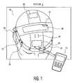
- FIG. 1shows an exemplary embodiment of a wearable EEG system 5 according to the present invention.
- the system 5may be embodied as a seizure detector headset which comprises a wearable EEG arrangement 10 communicatively linked to a computing device 15 .
- the wearable EEG arrangement 10includes a headband 20 (or cap) that is sized and shaped to be mounted/worn on the head (or scalp) as shown in FIG. 1 .
- the headband 20is adjustable (e.g., mechanically, elastic, etc.) so that the wearable EEG arrangement 10 may be used on multiple subjects and allow a particular subject to rent/lease the wearable EEG system 5 for diagnostic intervals.
- the headband 20may be fitted to the particular subject when, for example, the subject is required by a physician to utilize the system 5 at all times.
- a plurality of EEG electrodes 25may be affixed to predetermined locations on the headband 20 so that when the headband 20 is worn, the EEG electrodes 25 are disposed in corresponding locations on the scalp.
- the headband 20includes eight EEG electrodes 25 and two reference electrodes 28 which are attached to, for example, the ears.
- One exemplary electrode configurationcomprises FP 1 , F 7 , C 3 and P 7 active electrodes on the left hemisphere and FP 2 , F 8 , C 4 and P 8 active electrodes on the right hemisphere.
- any other electrode configurationcan readily be arranged.
- the EEG electrodes 25When the headband 20 is worn, the EEG electrodes 25 come in contact with the scalp to detect neurophysiological activity by measuring an intensity and pattern of electrical signals generated by the brain. Spontaneous oscillations in the electrical signals are typically referred to as brain waves or EEG.
- the EEGis a record derived from the spontaneously oscillating electrical signals and other electrical activity (e.g., “noise” or electrical activity of a non-cerebral origin).
- the number and configuration of the EEG electrodes 25 and the reference electrodes 28may depend upon, for example, the subject's medical history, a diagnostic task, etc.
- the electrical signals detected by the EEG electrodes 25 and the reference electrodes 28may be output to a processing unit 30 for analysis.
- the processing unit 30is disposed on a cross-band of the headband 20 which runs transversely over the scalp.
- the processing unit 30may be disposed anywhere on the headband 20 .
- the processing unit 30may amplify, filter and/or digitize the electrical signals and determine whether the electrical signals are indicative of a target brain activity such as an epileptic event.
- the processing unit 30may activate components of the system 5 , transmit a warning signal(s) to one or more remote computing arrangements (e.g., the computing device 15 , a server, etc.) and save EEG data corresponding to the electrical signals on a storage device (e.g., a removable memory card 32 coupled to the processing unit 30 , a remote database, etc.). Operation of the processing unit 30 will be explained further below.
- a warning signal(s)e.g., the computing device 15 , a server, etc.
- a storage devicee.g., a removable memory card 32 coupled to the processing unit 30 , a remote database, etc.
- the headband 20also includes an image capture device (e.g., a video camera 35 , a digital camera).
- an image capture devicee.g., a video camera 35 , a digital camera.
- the video camera 35is preferably focused downward so that an imaging field of the video camera 35 includes of the subject's trunk, hands and feet.
- the video camera 35may be statically positioned on the headband 20 or moveable and/or rotatable relative thereto.
- the headband 20may further include a radio frequency transceiver 40 for conducting wireless communications, an indicator (e.g., LEDs 45 , speaker, etc.) for providing visual (or audible) signals (e.g., indicating that an epileptic event has been detected), and a battery 50 providing power to the components of the wearable EEG arrangement 10 .
- the transceiver 40may allow the processing unit 30 to, for example, exchange data, including the EEG data, warning signals and instructions with the computing device 15 .
- the LEDs 45may be activated upon detection of an epileptic event. Upon noticing activation of the LEDs 45 , a nurse, physician or the subject may administer anti-epileptic medication to prevent the occurrence of the epileptic event or reduce the severity thereof.
- the battery 50may be a rechargeable battery (e.g., Li ion) or single-use/alkaline which has, for example, a voltage of 3.6V and provides a current of 1000 mA.
- the system 5may also include the computing device 15 which is communicatively linked to the wearable EEG arrangement 10 .
- the computing device 15may be any processor-based device including, but not limited to, a mobile phone, a PDA, a laptop, a tablet computer, a handheld computer, a PC or any of a number of computers accessed via a network such as the Internet, a WLAN, etc.
- the computing device 15may simply be a display arrangement such as, for example an LCD display screen or CRT.
- the computing device 15may be used to monitor EEG data, receive warning signals when an epileptic event is detected, activate the wearable EEG arrangement 10 , etc.
- the computing device 15may be further utilized to review the EEG data obtained by from the EEG electrodes 25 and video data captured by the video camera 35 to diagnose the subject, update a previous diagnosis of the subject, prescribe/update a treatment protocol, etc.
- the wearable EEG arrangement 10is placed on the head.
- the reference electrodes 28are attached to the ears and the EEG electrodes 25 are placed in contact with the scalp.
- FIGS. 3 a - bshow an exemplary embodiment of an EEG electrode unit 300 which includes one of the EEG electrodes 25 and facilitates attachment of the EEG electrode 25 to the scalp, ensuring that substantially noise- and artifact-free EEG electrical signals are harvested.
- Each of the EEG electrodes 25 utilized by the wearable EEG arrangement 10may be included in a respective EEG electrode unit 300 .
- a plurality of EEG electrode units 300may be disposed on the headband 20 .
- the EEG electrode unit 300comprises a housing 305 which holds the EEG electrode 25 and an operational amplifier 310 coupled thereto. An output of the operational amplifier 310 is coupled to a cable 315 which leads to the processing unit 30 .
- the housing 305may be substantially cylindrical with an open bottom portion and a threaded upper portion.
- the EEG electrode 25may fit within the open bottom portion so that a detecting face of the EEG electrode 25 contacts the skin when the headband 20 is worn.
- a threaded plug 320mates with the threaded upper portion of the housing 305 . As shown in FIG.
- rotation of the plug 320expunges adhesive from one or more channels 325 formed within the housing 305 so that the adhesive exits the channels 325 seeping between the bottom portion of the housing 305 and the skin to form a temporary bond therebetween.
- conductive pastemay be expunged from a central channel 330 , seeping between the EEG electrode 25 and the skin to form an electrically conductive bond therebetween.
- a visual indicatore.g., green-to-red color change
- on the plug 320may indicate that all of the adhesive and/or conductive paste has been expunged from the EEG electrode unit 300 .
- an upper portion of the central channel 330has threads (or other connectors) mating with threads on a central member formed on an underside of the plug 320 .
- An O-ring 335 disposed circumferentially around the central memberprevents backflow of the conductive paste while stoppers 340 in the channels 325 prevent back flow of the adhesive. Between uses the EEG electrode units 300 may be disposable or reloaded with the adhesive and the conductive paste.
- the plug 320may utilize a plunging action (syringe-like) to expunge the adhesive and paste.
- the EEG electrode units 300may not include the adhesive and/or paste, which may be applied by a nurse or physician.
- the operational amplifier 310may be included as part of the processing unit 30 or otherwise separated from the housing 305 .
- the signals from the EEG electrode units 300may be transmitted wirelessly to the processing unit as would be understood by those of skill in the art.
- the headband 20is placed on the scalp and the EEG electrodes 25 are aligned in their proper positions on the scalp.
- the headband 20may have a marker (e.g., center of the forehead) which allows the subject to align the EEG electrodes 25 in their proper positions.
- the plugs 320 of the EEG electrode units 300are rotated to apply the adhesive and the conductive paste to the scalp fixing the EEG electrode units 300 to the target locations and electrically coupling the EEG electrodes 25 to the scalp.
- the wearable EEG arrangement 10When the EEG electrodes 25 have been secured to the scalp, the wearable EEG arrangement 10 may be powered. In one exemplary embodiment, a switch is provided on the wearable arrangement EEG arrangement 10 which activates the processing unit 30 . In another exemplary embodiment, the processing unit 30 may receive a wireless activation signal from the computing device 15 via the transceiver 40 . When the processing unit 30 is activated, the EEG electrodes 25 , the video camera 35 , and/or the LEDs 45 may be initialized. For example, the processing unit 30 may harvest EEG data from the EEG electrodes 25 and/or the video data from the video camera 35 , and/or flash the LEDs 45 .
- Segments(e.g., 20 sec) of EEG data and/or the video data may be transmitted to the computing device 15 for display thereon. If the processing unit 30 does not detect an epileptic event, the computing device 15 transmits a monitoring initiation signal to the processing unit 30 via the transceiver 40 instructing the processing unit 30 to being its monitoring and response program.
- the monitoring and response program utilized by the processing unit 30is preferably a vector-analysis-based application as described in Kovacs L, Ludvig N., Devinsky O., Kuzniekcy R. I., “Vector-analysis: Low-power-requiring software for real-time EEG seizure recognition/prediction in hybrid neuroprosthetic devices,” Epilepsia 46 (Suppl. 8) 317-318 (2005) and U.S. patent application Ser. No. 11/224,661 entitled “Apparatus and Method for Monitoring and Treatment of Brain Disorders,” the entire disclosures of which are expressly incorporated herein by reference.
- the processing unit 30may monitor the EEG data provided by the EEG electrodes 25 to detect for an epileptic event.
- EEG-seizure recognition softwaremay be employed. However, this may increase the bulk of the system as the power required for other types of software may be greater.
- FIG. 2shows an exemplary embodiment of an architecture 200 of the wearable EEG arrangement 10 according to the present invention.
- the EEG electrode units 300 and the reference electrodes 28are electrically coupled to inputs of the processing unit 30 .
- the brain wavesare detected and converted into electrical signals by the EEG electrodes 25 .
- the electrical signals detected by each EEG electrode 25are passed through a corresponding operational amplifier 310 in the EEG electrode unit 300 to reduce and/or eliminate movement artifacts from the electrical signals.
- the operational amplifier 310may be directly coupled to the EEG electrode 25 .
- the artifact-free electrical signalsare then output to the processing unit 30 .
- the exemplary processing unit 30comprises an analog section 205 which receives electrical signals from the EEG electrode units 300 and a digital section 210 which digitizes and analyzes output from the analog section 205 to detect epileptic events.
- the analog section 205may include a series of amplifiers 215 (e.g., differential amplifiers) and filters (e.g., band-pass and notch filters 220 ) for amplifying and filtering the electrical signals from the EEG electrode units 300 .
- the analog section 205may output segments of the electrical signals which are useful in the analysis of epileptic events.
- the band-pass filtersmay be preset to a band-pass of 0.5-35 Hz for indicating an ongoing seizure, or to a band-pass of 0.5-200 Hz to indicate both an ongoing seizure and the imminent development of a seizure.
- the output of the analog section 205is passed to the digital section 210 and, in particular, a microprocessor 225 with an analog-to-digital (ADC) converter to digitize the segments of the electrical signals and generate digital EEG data.
- the digital section 210may further include a real time clock 230 for time-stamping the EEG data and a field-programmable gate array (FPGA) 235 for controlling and obtaining video data from the video camera 35 and writing the EEG data and/or the video data to the memory card 32 .
- FPGAfield-programmable gate array
- the memory card 32may be a 512 MB high-speed Secure Digital (SD) memory card, but those of skill in the art will understand that other removable memory arrangements may be used with the wearable memory arrangement 10 , e.g., a CF card, a PCMCIA card, a memory stick, a USB device, a MMC card, an xD-picture card, a smartmedia card, etc. Those of skill in the art will understand that a non-removable may also be utilized.
- SDSecure Digital
- the digital section 210may further include a memory (not shown) storing reference data corresponding to EEG data indicative of epileptic events.
- the reference datamay include previous EEG data recorded from the subject or from a group of subjects during one or more epileptic events.
- the reference datamay be a function or other representation which has been constructed based on such EEG data.
- the memory card 32may store the reference data tailored for use by a particular subject.
- the computing device 15may store or have access to the reference data. In this embodiment, the computing device 15 , rather than the processing unit 30 , may detect the occurrence of epileptic events.
- the microprocessor 225analyzes the EEG data to detect epileptic events. That is, the EEG data is compared to the reference data to determine whether the subject is experiencing an epileptic event. If the EEG data is not indicative of an epileptic event, the EEG data may be discarded after a predetermined time. For example, a delay may be used so that the EEG data recorded previous to an epileptic event may be reviewed. Alternatively, all (or selected portions) of the EEG data may be stored on the memory card 32 and/or transmitted to the computing device 15 for long-term analysis.
- the processing unit 30may write the EEG data to the memory card 32 for a predetermined duration (e.g., about 10-30 seconds).
- the predetermined durationmay be selected to correspond to a duration of the epileptic event, i.e., the predetermined time equals the time during which the EEG data is indicative of an ongoing epileptic event.
- the processing unit 30may continue to write EEG data to the memory card 32 for a predetermined time after cessation of the epileptic event.
- anti-epileptic drugs or other seizure treatmentsmay be evaluated for their ability to quell the seizure and/or return the subject to a normal EEG.
- the EEG datamay be downloaded (e.g., batch, streamed) to the computing device 15 when the processing unit 30 detects the epileptic event or onset thereof.
- a nurse, physician or other caregivermay monitor the EEG data to determine the severity of epileptic events, a proper treatment, etc.
- the processing unit 30Upon detecting an epileptic event, the processing unit 30 preferably also activates the video camera 35 . As shown in FIG. 4 , the video camera 35 captures video data during the epileptic event. The processing unit 30 may then write the video data to the memory card 32 or download this data to the computing device 15 . The video camera 35 is preferably activated for so long as the EEG data is recorded. Thus, video of the epileptic event may be analyzed in conjunction with the EEG data that was exhibited during the epileptic event. Those skilled in the art will understand that, if memory capacity is sufficient, the video and EEG data may be continuously recorded for later analysis with portions indicative of ongoing to imminent seizure activity flagged.
- the processing unit 30may also transmit a warning signal and/or activate the LEDs 45 .
- the warning signalmay be a wireless signal transmitted to the computing device 15 .
- the warning signalmay be a broadcast signal so that any wireless computing device in range of the transceiver 40 may detect and respond to the warning signal.
- the warning signalmay include data which, for example, identifies the subject (e.g., name, age, etc.), includes medical history data (e.g., diagnosis, treatments, severity, etc.), identifies a location of the subject, etc.
- the memory card 32may be removed from the wearable EEG arrangement 10 and coupled to the computing device 15 .
- the EEG data and the video datamay then be stored in a database and/or analyzed to determined/update a diagnosis of the subject, prescribe a treatment protocol, etc.
- this datamay be transmitted wirelessly to the computing device 15 or via a cabled connection without removing the memory card 32 .
- FIG. 5shows another exemplary embodiment of a wearable EEG system 500 according to the present invention.
- the wearable EEG system 500includes a wearable EEG arrangement (e.g., an EEG minidisc 505 ) and an image capture device (e.g., a video camera unit 510 ).
- the wearable EEG system 500preferably includes only a single EEG minidisc 505 which performs EEG data acquisition, data analysis and signaling functions while the video camera unit 510 is a separately wearable device which includes a video camera 512 and a transceiver 514 for wirelessly communicating with the EEG minidisc 505 .
- EEG minidiscs 505may vary as desired/prescribed, and that the EEG minidisc 505 may be physically coupled to the video camera 510 , in which case the video camera 510 may not require the transceiver 514 .
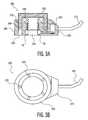
- an EEG minidisc 505includes a housing 515 with two EEG electrodes 520 disposed on a bottom surface thereof.
- a channel 525 extending through the housing 515 from a top surface to the bottom surfaceallows the conductive paste to be applied to a bottom surface of the EEG electrodes 520 .
- the adhesive for securing the EEG minidisc 505 to the scalpmay also be applied through the channel 525 , through other channels or directly to the scalp and/or to the bottom surface of the housing 515 .
- a processing unit 530 included in the housing 515 of the EEG minidisc 505may include one or more amplifiers and filters, in addition to a microprocessor.
- the processing unit 530may perform functions similar to those performed by the processing unit 30 described above. That is, the electrical signals obtained by the EEG electrodes 520 may be amplified, filtered (e.g., digital post-filtering) and digitized to generate the digital EEG data, and the EEG data may be analyzed by the microprocessor to detect the occurrence of an epileptic event or the imminent onset thereof, at which time the EEG minidisc 505 may activate the video camera 512 .
- the processing unit 530may also transfer the EEG data to a memory on the EEG minidisc 505 and/or transmit the EEG data as a wireless signal (e.g., optical, RF) to a remote computing device.
- a wireless signale.g., optical, RF
- the EEG minidisc 505may further include a battery 535 , a battery charging circuit 540 , an optical transceiver 545 and an RF transceiver 550 .
- the battery charging circuit 540may be, for example, a magnetic coupling circuit which may be coupled to a charger/data reader to be charged and exchange data with a computing device, as will be described further below.
- the optical transceiver 545may be used to exchange data with the computing device, and the RF transceiver 550 may transmit signals to the receiver 514 on the video camera unit 510 .
- the EEG minidisc 505may further include an indicator (e.g., LED, speaker, etc.) which is activated upon detection of an occurring or imminent epileptic event.
- FIG. 7shows an exemplary embodiment of an architecture of the EEG minidisc 505 according to the present invention.
- the EEG electrodes 520are coupled to the housing 515 and pass, to the processing unit 530 , electrical signals corresponding to detected brain waves.
- the electrical signalsare amplified by an amplifier 705 (e.g., an instrumentation amplifier), filtered by a filter 710 (e.g., a band-pass and notch filter) and digitized and processed by a microprocessor 715 (e.g., a low-power micro with a 12 bit ADC) to generate digital EEG data.
- an amplifier 705e.g., an instrumentation amplifier
- a filter 710e.g., a band-pass and notch filter
- microprocessor 715e.g., a low-power micro with a 12 bit ADC
- the microprocessor 715may then compare the EEG data to reference data stored in a memory 720 (e.g., a non-volatile memory) in the EEG minidisc 505 to determine the occurrence or likelihood of occurrence in the near future of an epileptic event or onset thereof.
- a memory 720e.g., a non-volatile memory
- the microprocessor 715may transmit an activation signal via the transceiver 550 to the receiver 514 on the video camera unit 510 , activating the video camera 512 .
- the transceiver 550may also be used to transmit a warning signal upon detection of the epileptic event.
- the EEG minidisc 505may also incorporate an optical transceiver 545 to receive optical activation signals from an optical transmitter.
- a video camera unit 510resides in a wearable housing 805 which may be, for example, an earpiece, a headband, a cap, etc.
- the housing 805may include a microprocessor 810 for activating the video camera 512 upon receipt of the activation signal via the receiver 514 .
- the microprocessor 810may write video data obtained by the video camera 512 to a memory 815 (e.g., a removable, non-volatile memory) and download the video data to a wireless communication device (e.g., mobile phone, PDA, laptop, tablet, handheld computer, network interface card, etc.) via a wireless communication circuit (e.g., a cellular phone circuit 820 ).
- a wireless communication devicee.g., mobile phone, PDA, laptop, tablet, handheld computer, network interface card, etc.
- a wireless communication circuite.g., a cellular phone circuit 820
- the microprocessor 810may instruct the cellular phone circuit 820 to transmit warning signals to a remote communication device, such as the computing device 15 .
- the video camera unit 510may be powered by a battery 825 which is recharged when coupled to a charging device, as described below.
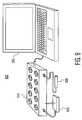
- a charger/data reader system 900may include a computing device 905 (e.g., a laptop, PC, tablet, etc.) coupled to a multiport charger and data reader (MCDR) 910 . While the MCDR 910 may be used for charging a plurality of EEG minidiscs 505 and/or video camera units 510 simultaneously, those of skill in the art will understand that the MCDR 910 may only accommodate one or a preselected number of EEG minidiscs 505 and/or video camera units 510 . In the exemplary embodiment, the MCDR 910 includes a plurality of charging ports for receiving the EEG minidiscs 505 .
- the battery charging circuit 540receives power from the MCDR 910 and charges the battery 535 .
- the battery 825may receive power from the MCDR 910 .
- the EEG data and the video datamay be downloaded from the memory 720 and/or the memory 815 for subsequent uploading to the computing device 905 .
- the MCDR 910may further include an RF receiver 915 for wirelessly downloading the EEG data and/or the video data from the EEG minidisc 505 or the cellular phone circuit 820 .
- the MCDR 910may also be equipped with an optical transmitter 920 for activating the EEG minidisc 505 via the optical transceiver 545 of the EEG minidisc.
- the computing device 905may utilize EEG processing algorithms and/or image processing algorithms to analyze the epileptic events suffered by the subject.
Landscapes
- Health & Medical Sciences (AREA)
- Life Sciences & Earth Sciences (AREA)
- Surgery (AREA)
- Biophysics (AREA)
- Pathology (AREA)
- Engineering & Computer Science (AREA)
- Biomedical Technology (AREA)
- Heart & Thoracic Surgery (AREA)
- Medical Informatics (AREA)
- Molecular Biology (AREA)
- Physics & Mathematics (AREA)
- Animal Behavior & Ethology (AREA)
- General Health & Medical Sciences (AREA)
- Public Health (AREA)
- Veterinary Medicine (AREA)
- Neurology (AREA)
- Neurosurgery (AREA)
- Physiology (AREA)
- Psychiatry (AREA)
- Psychology (AREA)
- Measurement And Recording Of Electrical Phenomena And Electrical Characteristics Of The Living Body (AREA)
Abstract
Description
Claims (22)
Priority Applications (1)
| Application Number | Priority Date | Filing Date | Title |
|---|---|---|---|
| US11/524,160US7885706B2 (en) | 2006-09-20 | 2006-09-20 | System and device for seizure detection |
Applications Claiming Priority (1)
| Application Number | Priority Date | Filing Date | Title |
|---|---|---|---|
| US11/524,160US7885706B2 (en) | 2006-09-20 | 2006-09-20 | System and device for seizure detection |
Publications (3)
| Publication Number | Publication Date |
|---|---|
| US20080082019A1 US20080082019A1 (en) | 2008-04-03 |
| US20090281446A2 US20090281446A2 (en) | 2009-11-12 |
| US7885706B2true US7885706B2 (en) | 2011-02-08 |
Family
ID=39284291
Family Applications (1)
| Application Number | Title | Priority Date | Filing Date |
|---|---|---|---|
| US11/524,160Expired - Fee RelatedUS7885706B2 (en) | 2006-09-20 | 2006-09-20 | System and device for seizure detection |
Country Status (1)
| Country | Link |
|---|---|
| US (1) | US7885706B2 (en) |
Cited By (17)
| Publication number | Priority date | Publication date | Assignee | Title |
|---|---|---|---|---|
| US20090247894A1 (en)* | 2008-03-31 | 2009-10-01 | Brainscope Company, Inc. | Systems and Methods For Neurological Evaluation and Treatment Guidance |
| WO2015184391A1 (en)* | 2014-05-29 | 2015-12-03 | Gil Da Costa Ricardo | Physiological signal detection and analysis systems and devices |
| US20160206871A1 (en)* | 2012-11-16 | 2016-07-21 | Rio Grande Neurosciences, Inc. | Variably configurable, adaptable electrode arrays and effectuating software, methods, and systems |
| US9408575B2 (en) | 2009-04-29 | 2016-08-09 | Bio-Signal Group Corp. | EEG kit |
| US20170215759A1 (en)* | 2016-02-01 | 2017-08-03 | Epitel, Inc. | Self-Contained EEG Recording System |
| US9814426B2 (en) | 2012-06-14 | 2017-11-14 | Medibotics Llc | Mobile wearable electromagnetic brain activity monitor |
| US10067565B2 (en) | 2016-09-29 | 2018-09-04 | Intel Corporation | Methods and apparatus for identifying potentially seizure-inducing virtual reality content |
| US10130277B2 (en) | 2014-01-28 | 2018-11-20 | Medibotics Llc | Willpower glasses (TM)—a wearable food consumption monitor |
| US10188307B2 (en) | 2012-02-23 | 2019-01-29 | Bio-Signal Group Corp. | Shielded multi-channel EEG headset systems and methods |
| US10234942B2 (en) | 2014-01-28 | 2019-03-19 | Medibotics Llc | Wearable and mobile brain computer interface (BCI) device and method |
| EP3632299A1 (en)* | 2018-10-05 | 2020-04-08 | Epihunter NV | Method and system for monitoring a subject |
| US10946196B2 (en) | 2012-11-16 | 2021-03-16 | Stimscience Inc. | System for variably configurable, adaptable electrode arrays and effectuating software |
| US11172859B2 (en) | 2014-01-28 | 2021-11-16 | Medibotics | Wearable brain activity device with auditory interface |
| WO2021255751A1 (en)* | 2020-06-16 | 2021-12-23 | Indrani Bhattacherjee | System and method for predicting epileptic seizures in real time |
| US11633144B2 (en) | 2020-04-05 | 2023-04-25 | Epitel, Inc. | EEG recording and analysis |
| US11662819B2 (en) | 2015-05-12 | 2023-05-30 | Medibotics | Method for interpreting a word, phrase, and/or command from electromagnetic brain activity |
| US11857330B1 (en) | 2022-10-19 | 2024-01-02 | Epitel, Inc. | Systems and methods for electroencephalogram monitoring |
Families Citing this family (82)
| Publication number | Priority date | Publication date | Assignee | Title |
|---|---|---|---|---|
| WO2007075477A2 (en)* | 2005-12-19 | 2007-07-05 | University Of Florida | Closed-loop state-dependent seizure prevention systems |
| US8160688B2 (en)* | 2006-04-12 | 2012-04-17 | Vyssotski Alexei L | Integrated self-contained recorder of biological data for small animal research |
| US20080021341A1 (en) | 2006-06-23 | 2008-01-24 | Neurovista Corporation A Delware Corporation | Methods and Systems for Facilitating Clinical Trials |
| GB0615463D0 (en)* | 2006-08-03 | 2006-09-13 | Imp College Innovations Ltd | Apparatus and method for obtaining EEG data |
| US8295934B2 (en) | 2006-11-14 | 2012-10-23 | Neurovista Corporation | Systems and methods of reducing artifact in neurological stimulation systems |
| WO2008092133A2 (en)* | 2007-01-25 | 2008-07-31 | Neurovista Corporation | Methods and systems for measuring a subject's susceptibility to a seizure |
| EP2126785A2 (en) | 2007-01-25 | 2009-12-02 | NeuroVista Corporation | Systems and methods for identifying a contra-ictal condition in a subject |
| US8036736B2 (en) | 2007-03-21 | 2011-10-11 | Neuro Vista Corporation | Implantable systems and methods for identifying a contra-ictal condition in a subject |
| US20090024049A1 (en)* | 2007-03-29 | 2009-01-22 | Neurofocus, Inc. | Cross-modality synthesis of central nervous system, autonomic nervous system, and effector data |
| US9886981B2 (en)* | 2007-05-01 | 2018-02-06 | The Nielsen Company (Us), Llc | Neuro-feedback based stimulus compression device |
| EP2142082A4 (en) | 2007-05-01 | 2015-10-28 | Neurofocus Inc | Neuro-informatics repository system |
| WO2008144569A1 (en)* | 2007-05-16 | 2008-11-27 | Neurofocus, Inc. | Habituation analysis using central nervous system, autonomic nervous system and effector system measurements |
| US8392253B2 (en) | 2007-05-16 | 2013-03-05 | The Nielsen Company (Us), Llc | Neuro-physiology and neuro-behavioral based stimulus targeting system |
| US8494905B2 (en) | 2007-06-06 | 2013-07-23 | The Nielsen Company (Us), Llc | Audience response analysis using simultaneous electroencephalography (EEG) and functional magnetic resonance imaging (fMRI) |
| US9788744B2 (en)* | 2007-07-27 | 2017-10-17 | Cyberonics, Inc. | Systems for monitoring brain activity and patient advisory device |
| US8533042B2 (en)* | 2007-07-30 | 2013-09-10 | The Nielsen Company (Us), Llc | Neuro-response stimulus and stimulus attribute resonance estimator |
| US8386313B2 (en) | 2007-08-28 | 2013-02-26 | The Nielsen Company (Us), Llc | Stimulus placement system using subject neuro-response measurements |
| JP5539876B2 (en)* | 2007-08-28 | 2014-07-02 | ニューロフォーカス・インコーポレーテッド | Consumer experience assessment device |
| US8635105B2 (en) | 2007-08-28 | 2014-01-21 | The Nielsen Company (Us), Llc | Consumer experience portrayal effectiveness assessment system |
| US8392255B2 (en) | 2007-08-29 | 2013-03-05 | The Nielsen Company (Us), Llc | Content based selection and meta tagging of advertisement breaks |
| US20090083129A1 (en) | 2007-09-20 | 2009-03-26 | Neurofocus, Inc. | Personalized content delivery using neuro-response priming data |
| US8494610B2 (en) | 2007-09-20 | 2013-07-23 | The Nielsen Company (Us), Llc | Analysis of marketing and entertainment effectiveness using magnetoencephalography |
| EP2211708A1 (en) | 2007-10-23 | 2010-08-04 | Optima Neuroscience, Inc. | System for seizure monitoring and detection |
| US20090171168A1 (en)* | 2007-12-28 | 2009-07-02 | Leyde Kent W | Systems and Method for Recording Clinical Manifestations of a Seizure |
| US9259591B2 (en) | 2007-12-28 | 2016-02-16 | Cyberonics, Inc. | Housing for an implantable medical device |
| WO2010065741A1 (en)* | 2008-12-04 | 2010-06-10 | Neurovista Corporation | Universal electrode array for monitoring brain activity |
| US8849390B2 (en)* | 2008-12-29 | 2014-09-30 | Cyberonics, Inc. | Processing for multi-channel signals |
| US8588933B2 (en) | 2009-01-09 | 2013-11-19 | Cyberonics, Inc. | Medical lead termination sleeve for implantable medical devices |
| US8270814B2 (en) | 2009-01-21 | 2012-09-18 | The Nielsen Company (Us), Llc | Methods and apparatus for providing video with embedded media |
| US9357240B2 (en) | 2009-01-21 | 2016-05-31 | The Nielsen Company (Us), Llc | Methods and apparatus for providing alternate media for video decoders |
| US8464288B2 (en) | 2009-01-21 | 2013-06-11 | The Nielsen Company (Us), Llc | Methods and apparatus for providing personalized media in video |
| US20100250325A1 (en) | 2009-03-24 | 2010-09-30 | Neurofocus, Inc. | Neurological profiles for market matching and stimulus presentation |
| WO2010129026A2 (en)* | 2009-04-29 | 2010-11-11 | Bio-Signal Group Corp. | Eeg kit |
| US8786624B2 (en)* | 2009-06-02 | 2014-07-22 | Cyberonics, Inc. | Processing for multi-channel signals |
| US20110046473A1 (en)* | 2009-08-20 | 2011-02-24 | Neurofocus, Inc. | Eeg triggered fmri signal acquisition |
| US20110046502A1 (en)* | 2009-08-20 | 2011-02-24 | Neurofocus, Inc. | Distributed neuro-response data collection and analysis |
| US8655437B2 (en)* | 2009-08-21 | 2014-02-18 | The Nielsen Company (Us), Llc | Analysis of the mirror neuron system for evaluation of stimulus |
| US10987015B2 (en) | 2009-08-24 | 2021-04-27 | Nielsen Consumer Llc | Dry electrodes for electroencephalography |
| MY166001A (en)* | 2009-10-27 | 2018-05-21 | Neurovigil Inc | Head harness & wireless eeg monitoring system |
| US20110106750A1 (en) | 2009-10-29 | 2011-05-05 | Neurofocus, Inc. | Generating ratings predictions using neuro-response data |
| US9560984B2 (en) | 2009-10-29 | 2017-02-07 | The Nielsen Company (Us), Llc | Analysis of controlled and automatic attention for introduction of stimulus material |
| US8209224B2 (en) | 2009-10-29 | 2012-06-26 | The Nielsen Company (Us), Llc | Intracluster content management using neuro-response priming data |
| US8335716B2 (en)* | 2009-11-19 | 2012-12-18 | The Nielsen Company (Us), Llc. | Multimedia advertisement exchange |
| US8335715B2 (en)* | 2009-11-19 | 2012-12-18 | The Nielsen Company (Us), Llc. | Advertisement exchange using neuro-response data |
| US9643019B2 (en)* | 2010-02-12 | 2017-05-09 | Cyberonics, Inc. | Neurological monitoring and alerts |
| US20110237971A1 (en)* | 2010-03-25 | 2011-09-29 | Neurofocus, Inc. | Discrete choice modeling using neuro-response data |
| US8684742B2 (en) | 2010-04-19 | 2014-04-01 | Innerscope Research, Inc. | Short imagery task (SIT) research method |
| US8655428B2 (en) | 2010-05-12 | 2014-02-18 | The Nielsen Company (Us), Llc | Neuro-response data synchronization |
| US8392250B2 (en) | 2010-08-09 | 2013-03-05 | The Nielsen Company (Us), Llc | Neuro-response evaluated stimulus in virtual reality environments |
| US8392251B2 (en) | 2010-08-09 | 2013-03-05 | The Nielsen Company (Us), Llc | Location aware presentation of stimulus material |
| US8396744B2 (en) | 2010-08-25 | 2013-03-12 | The Nielsen Company (Us), Llc | Effective virtual reality environments for presentation of marketing materials |
| WO2012036639A1 (en)* | 2010-09-16 | 2012-03-22 | National University Of Singapore | Eeg electrodes with gated electrolyte storage chamber and an adjustable eeg headset assembly |
| US8983591B2 (en) | 2010-10-15 | 2015-03-17 | Brain Sentinel, Inc. | Method and apparatus for detecting seizures |
| US10226209B2 (en) | 2010-10-15 | 2019-03-12 | Brain Sentinel, Inc. | Method and apparatus for classification of seizure type and severity using electromyography |
| US20140038147A1 (en) | 2011-01-21 | 2014-02-06 | Fondamenta, Llc | Electrode for Attention Training Techniques |
| BR112014000106A8 (en) | 2011-07-05 | 2018-02-06 | Brain Sentinel Inc | METHOD AND DEVICE FOR DETECTING SEIZURES |
| US9292858B2 (en) | 2012-02-27 | 2016-03-22 | The Nielsen Company (Us), Llc | Data collection system for aggregating biologically based measures in asynchronous geographically distributed public environments |
| US9569986B2 (en) | 2012-02-27 | 2017-02-14 | The Nielsen Company (Us), Llc | System and method for gathering and analyzing biometric user feedback for use in social media and advertising applications |
| US9451303B2 (en) | 2012-02-27 | 2016-09-20 | The Nielsen Company (Us), Llc | Method and system for gathering and computing an audience's neurologically-based reactions in a distributed framework involving remote storage and computing |
| GB201209975D0 (en)* | 2012-06-06 | 2012-07-18 | Univ Exeter | Assessing susceptibility to epilepsy and epileptic seizures |
| US20140024913A1 (en)* | 2012-07-18 | 2014-01-23 | Neurotopia, Inc. | Neurophysiologic performance measurement and training system |
| US8989835B2 (en) | 2012-08-17 | 2015-03-24 | The Nielsen Company (Us), Llc | Systems and methods to gather and analyze electroencephalographic data |
| EP3235426A3 (en)* | 2012-10-15 | 2018-02-21 | Jordan Neuroscience, Inc. | Wireless eeg unit |
| US9320450B2 (en) | 2013-03-14 | 2016-04-26 | The Nielsen Company (Us), Llc | Methods and apparatus to gather and analyze electroencephalographic data |
| JP6615089B2 (en)* | 2013-06-11 | 2019-12-04 | コーニンクレッカ フィリップス エヌ ヴェ | System, method and device for monitoring light and sound impact on a person |
| US9622702B2 (en) | 2014-04-03 | 2017-04-18 | The Nielsen Company (Us), Llc | Methods and apparatus to gather and analyze electroencephalographic data |
| CN104605844A (en)* | 2015-01-26 | 2015-05-13 | 山东大学齐鲁医院 | Portable electroencephalograph head-mounted part |
| US9936250B2 (en) | 2015-05-19 | 2018-04-03 | The Nielsen Company (Us), Llc | Methods and apparatus to adjust content presented to an individual |
| US9712736B2 (en)* | 2015-12-15 | 2017-07-18 | Intel Coprporation | Electroencephalography (EEG) camera control |
| US11517248B2 (en) | 2016-03-04 | 2022-12-06 | University Of Tennessee Research Foundation | Ambulatory seizure monitoring system and method |
| US10506974B2 (en) | 2016-03-14 | 2019-12-17 | The Nielsen Company (Us), Llc | Headsets and electrodes for gathering electroencephalographic data |
| MX2018012853A (en) | 2016-04-19 | 2019-03-28 | Brain Sentinel Inc | Systems and methods for characterization of seizures. |
| WO2018057667A1 (en)* | 2016-09-20 | 2018-03-29 | Paradromics, Inc. | Systems and methods for detecting corrupt or inaccurate sensory representations |
| CN110575165A (en)* | 2019-09-25 | 2019-12-17 | 北京脑陆科技有限公司 | APP used for brain monitoring and intervention in cooperation with EEG equipment |
| CN110833394A (en)* | 2019-11-13 | 2020-02-25 | 段艳文 | Device for dynamically early warning epileptic seizure |
| GB201917526D0 (en)* | 2019-11-29 | 2020-01-15 | Mbraintrain Llc | Seizure logging |
| US20210282701A1 (en)* | 2020-03-16 | 2021-09-16 | nCefalon Corporation | Method of early detection of epileptic seizures through scalp eeg monitoring |
| CN114099174B (en)* | 2020-06-09 | 2023-04-25 | 首都医科大学宣武医院 | Monitoring system and method for epileptic children patients |
| WO2022046740A1 (en)* | 2020-08-26 | 2022-03-03 | Brain Scientific, Inc. | Integrated brain machine interface platform with graphene based electrodes |
| WO2022204433A1 (en)* | 2021-03-24 | 2022-09-29 | Jumbe Nelson L | Systems and methods for measuring intracranial pressure |
| EP4489655A1 (en)* | 2022-03-10 | 2025-01-15 | Ice Neurosystems, Inc | Systems and methods for guided eeg stimulation |
| WO2024200131A1 (en)* | 2023-03-27 | 2024-10-03 | Sony Semiconductor Solutions Corporation | Processor, headband and method |
Citations (8)
| Publication number | Priority date | Publication date | Assignee | Title |
|---|---|---|---|---|
| US5564433A (en)* | 1994-12-19 | 1996-10-15 | Thornton; Kirtley E. | Method for the display, analysis, classification, and correlation of electrical brain function potentials |
| US6148280A (en)* | 1995-02-28 | 2000-11-14 | Virtual Technologies, Inc. | Accurate, rapid, reliable position sensing using multiple sensing technologies |
| US6473639B1 (en)* | 2000-03-02 | 2002-10-29 | Neuropace, Inc. | Neurological event detection procedure using processed display channel based algorithms and devices incorporating these procedures |
| US20060111644A1 (en)* | 2004-05-27 | 2006-05-25 | Children's Medical Center Corporation | Patient-specific seizure onset detection system |
| US7155276B2 (en)* | 2001-07-17 | 2006-12-26 | Lamont John | Method and apparatus to modify cranial electrical potentials to remediate psychiatric disorders and to enhance optimal brain functioning |
| US7277758B2 (en)* | 1998-08-05 | 2007-10-02 | Neurovista Corporation | Methods and systems for predicting future symptomatology in a patient suffering from a neurological or psychiatric disorder |
| US20070287931A1 (en)* | 2006-02-14 | 2007-12-13 | Dilorenzo Daniel J | Methods and systems for administering an appropriate pharmacological treatment to a patient for managing epilepsy and other neurological disorders |
| US20080021340A1 (en)* | 2006-07-19 | 2008-01-24 | Mika Sarkela | Detection of focal epileptiform activity |
- 2006
- 2006-09-20USUS11/524,160patent/US7885706B2/ennot_activeExpired - Fee Related
Patent Citations (8)
| Publication number | Priority date | Publication date | Assignee | Title |
|---|---|---|---|---|
| US5564433A (en)* | 1994-12-19 | 1996-10-15 | Thornton; Kirtley E. | Method for the display, analysis, classification, and correlation of electrical brain function potentials |
| US6148280A (en)* | 1995-02-28 | 2000-11-14 | Virtual Technologies, Inc. | Accurate, rapid, reliable position sensing using multiple sensing technologies |
| US7277758B2 (en)* | 1998-08-05 | 2007-10-02 | Neurovista Corporation | Methods and systems for predicting future symptomatology in a patient suffering from a neurological or psychiatric disorder |
| US6473639B1 (en)* | 2000-03-02 | 2002-10-29 | Neuropace, Inc. | Neurological event detection procedure using processed display channel based algorithms and devices incorporating these procedures |
| US7155276B2 (en)* | 2001-07-17 | 2006-12-26 | Lamont John | Method and apparatus to modify cranial electrical potentials to remediate psychiatric disorders and to enhance optimal brain functioning |
| US20060111644A1 (en)* | 2004-05-27 | 2006-05-25 | Children's Medical Center Corporation | Patient-specific seizure onset detection system |
| US20070287931A1 (en)* | 2006-02-14 | 2007-12-13 | Dilorenzo Daniel J | Methods and systems for administering an appropriate pharmacological treatment to a patient for managing epilepsy and other neurological disorders |
| US20080021340A1 (en)* | 2006-07-19 | 2008-01-24 | Mika Sarkela | Detection of focal epileptiform activity |
Cited By (35)
| Publication number | Priority date | Publication date | Assignee | Title |
|---|---|---|---|---|
| US20090247894A1 (en)* | 2008-03-31 | 2009-10-01 | Brainscope Company, Inc. | Systems and Methods For Neurological Evaluation and Treatment Guidance |
| US9408575B2 (en) | 2009-04-29 | 2016-08-09 | Bio-Signal Group Corp. | EEG kit |
| US10188307B2 (en) | 2012-02-23 | 2019-01-29 | Bio-Signal Group Corp. | Shielded multi-channel EEG headset systems and methods |
| US9814426B2 (en) | 2012-06-14 | 2017-11-14 | Medibotics Llc | Mobile wearable electromagnetic brain activity monitor |
| US10946196B2 (en) | 2012-11-16 | 2021-03-16 | Stimscience Inc. | System for variably configurable, adaptable electrode arrays and effectuating software |
| US20160206871A1 (en)* | 2012-11-16 | 2016-07-21 | Rio Grande Neurosciences, Inc. | Variably configurable, adaptable electrode arrays and effectuating software, methods, and systems |
| US12208264B2 (en) | 2012-11-16 | 2025-01-28 | Stimscience Inc. | System for variably configurable, adaptable electrode arrays and effectuating software |
| US11633595B2 (en) | 2012-11-16 | 2023-04-25 | Stimscience Inc. | System for variably configurable, adaptable electrode arrays and effectuating software |
| US10130277B2 (en) | 2014-01-28 | 2018-11-20 | Medibotics Llc | Willpower glasses (TM)—a wearable food consumption monitor |
| US10234942B2 (en) | 2014-01-28 | 2019-03-19 | Medibotics Llc | Wearable and mobile brain computer interface (BCI) device and method |
| US11172859B2 (en) | 2014-01-28 | 2021-11-16 | Medibotics | Wearable brain activity device with auditory interface |
| CN107072532A (en)* | 2014-05-29 | 2017-08-18 | 纽若瓦瑟股份有限公司 | Physiological signal detection and analysis system and equipment |
| US20170215757A1 (en)* | 2014-05-29 | 2017-08-03 | Neuroverse Inc. | Physiological signal detection and analysis systems and devices |
| WO2015184391A1 (en)* | 2014-05-29 | 2015-12-03 | Gil Da Costa Ricardo | Physiological signal detection and analysis systems and devices |
| US11662819B2 (en) | 2015-05-12 | 2023-05-30 | Medibotics | Method for interpreting a word, phrase, and/or command from electromagnetic brain activity |
| US11020035B2 (en)* | 2016-02-01 | 2021-06-01 | Epitel, Inc. | Self-contained EEG recording system |
| US11633139B2 (en)* | 2016-02-01 | 2023-04-25 | Epitel, Inc. | Self-contained EEG recording system |
| US20170215759A1 (en)* | 2016-02-01 | 2017-08-03 | Epitel, Inc. | Self-Contained EEG Recording System |
| US11969249B2 (en) | 2016-02-01 | 2024-04-30 | Epitel, Inc. | Self-contained EEG recording system |
| US20220338780A1 (en)* | 2016-02-01 | 2022-10-27 | c/o Epitel, Inc. | Self-contained eeg recording system |
| US10067565B2 (en) | 2016-09-29 | 2018-09-04 | Intel Corporation | Methods and apparatus for identifying potentially seizure-inducing virtual reality content |
| US10955917B2 (en) | 2016-09-29 | 2021-03-23 | Intel Corporation | Methods and apparatus for identifying potentially seizure-inducing virtual reality content |
| WO2020070340A1 (en)* | 2018-10-05 | 2020-04-09 | Epihunter Nv | Method and system for monitoring a subject |
| EP3632299A1 (en)* | 2018-10-05 | 2020-04-08 | Epihunter NV | Method and system for monitoring a subject |
| US12048554B2 (en) | 2020-04-05 | 2024-07-30 | Epitel, Inc. | EEG recording and analysis |
| US11779262B2 (en) | 2020-04-05 | 2023-10-10 | Epitel, Inc. | EEG recording and analysis |
| US11786167B2 (en) | 2020-04-05 | 2023-10-17 | Epitel, Inc. | EEG recording and analysis |
| US11638551B2 (en) | 2020-04-05 | 2023-05-02 | Epitel, Inc. | EEG recording and analysis |
| US11633144B2 (en) | 2020-04-05 | 2023-04-25 | Epitel, Inc. | EEG recording and analysis |
| US12357225B2 (en) | 2020-04-05 | 2025-07-15 | Epitel, Inc. | EEG recording and analysis |
| WO2021255751A1 (en)* | 2020-06-16 | 2021-12-23 | Indrani Bhattacherjee | System and method for predicting epileptic seizures in real time |
| US11857330B1 (en) | 2022-10-19 | 2024-01-02 | Epitel, Inc. | Systems and methods for electroencephalogram monitoring |
| US11918368B1 (en) | 2022-10-19 | 2024-03-05 | Epitel, Inc. | Systems and methods for electroencephalogram monitoring |
| US12070318B2 (en) | 2022-10-19 | 2024-08-27 | Epitel, Inc. | Systems and methods for electroencephalogram monitoring |
| US12350061B2 (en) | 2022-10-19 | 2025-07-08 | Epitel, Inc. | Systems and methods for electroencephalogram monitoring |
Also Published As
| Publication number | Publication date |
|---|---|
| US20090281446A2 (en) | 2009-11-12 |
| US20080082019A1 (en) | 2008-04-03 |
Similar Documents
| Publication | Publication Date | Title |
|---|---|---|
| US7885706B2 (en) | System and device for seizure detection | |
| US20210212564A1 (en) | Head Harness & Wireless EEG Monitoring System | |
| EP2583248B1 (en) | A method and a system for monitoring of sleep and other physiological conditions | |
| US20200138314A1 (en) | Modular ECG recording system suitable for wearable and handheld measurements | |
| US20140364756A1 (en) | Ecg sensing apparatuses, systems and methods | |
| US20070010748A1 (en) | Ambulatory monitors | |
| Brunnhuber et al. | Past, present and future of home video‐electroencephalographic telemetry: a review of the development of in‐home video‐electroencephalographic recordings | |
| WO2010129026A2 (en) | Eeg kit | |
| US20160192852A1 (en) | Wireless cardiac event recorder | |
| Kuzmin et al. | Device and software for mobile heart monitoring | |
| Juez et al. | Development of a wearable system with In-Ear EEG electrodes for the monitoring of brain activities: An application to epilepsy | |
| US20210022641A1 (en) | Wearable multi-modal bio-sensing system | |
| Lin et al. | Wearable and wireless brain-computer interface and its applications | |
| US20190274570A1 (en) | Electroencephalogram detection device and equipment | |
| US20210378583A1 (en) | Method and system for monitoring a subject | |
| US20230018876A1 (en) | Wearable Nystagmus Detection Devices and Methods for Using the Same | |
| CN109222901B (en) | Bioelectrical signal recorder and sleep monitoring system | |
| US20230181088A1 (en) | Mobile electroencephalogram system and methods | |
| KR101849857B1 (en) | Wearable living body diagnosis device | |
| RU2693217C1 (en) | Device for portable wireless recording of cerebral electrical activity | |
| US20240188923A1 (en) | Wearable stethoscope | |
| CA2896410A1 (en) | Smart wireless electrode array | |
| Juez Suárez | Development and implementation of a wearable system with ear-EEG for the monitoring of epileptic seizures | |
| CN115736941A (en) | Intelligent wearable animal electrocardiogram monitoring system | |
| US20170007141A1 (en) | Smart wireless electrode array |
Legal Events
| Date | Code | Title | Description |
|---|---|---|---|
| AS | Assignment | Owner name:NEW YORK UNIVERSITY, NEW YORK Free format text:ASSIGNMENT OF ASSIGNORS INTEREST;ASSIGNORS:LUDVIG, NANDOR;MEDVECZKY, GEZA;KUZNIECKY, RUBEN;AND OTHERS;REEL/FRAME:018333/0084 Effective date:20060915 | |
| STCF | Information on status: patent grant | Free format text:PATENTED CASE | |
| FPAY | Fee payment | Year of fee payment:4 | |
| FEPP | Fee payment procedure | Free format text:MAINTENANCE FEE REMINDER MAILED (ORIGINAL EVENT CODE: REM.); ENTITY STATUS OF PATENT OWNER: SMALL ENTITY | |
| FEPP | Fee payment procedure | Free format text:7.5 YR SURCHARGE - LATE PMT W/IN 6 MO, SMALL ENTITY (ORIGINAL EVENT CODE: M2555); ENTITY STATUS OF PATENT OWNER: SMALL ENTITY | |
| MAFP | Maintenance fee payment | Free format text:PAYMENT OF MAINTENANCE FEE, 8TH YR, SMALL ENTITY (ORIGINAL EVENT CODE: M2552); ENTITY STATUS OF PATENT OWNER: SMALL ENTITY Year of fee payment:8 | |
| FEPP | Fee payment procedure | Free format text:MAINTENANCE FEE REMINDER MAILED (ORIGINAL EVENT CODE: REM.); ENTITY STATUS OF PATENT OWNER: SMALL ENTITY | |
| LAPS | Lapse for failure to pay maintenance fees | Free format text:PATENT EXPIRED FOR FAILURE TO PAY MAINTENANCE FEES (ORIGINAL EVENT CODE: EXP.); ENTITY STATUS OF PATENT OWNER: SMALL ENTITY | |
| STCH | Information on status: patent discontinuation | Free format text:PATENT EXPIRED DUE TO NONPAYMENT OF MAINTENANCE FEES UNDER 37 CFR 1.362 | |
| FP | Lapsed due to failure to pay maintenance fee | Effective date:20230208 |