US7885206B2 - Method and system for topological navigation of hierarchical data groups - Google Patents
Method and system for topological navigation of hierarchical data groupsDownload PDFInfo
- Publication number
- US7885206B2 US7885206B2US12/397,356US39735609AUS7885206B2US 7885206 B2US7885206 B2US 7885206B2US 39735609 AUS39735609 AUS 39735609AUS 7885206 B2US7885206 B2US 7885206B2
- Authority
- US
- United States
- Prior art keywords
- logical group
- groups
- elements
- logical
- group
- Prior art date
- Legal status (The legal status is an assumption and is not a legal conclusion. Google has not performed a legal analysis and makes no representation as to the accuracy of the status listed.)
- Expired - Lifetime, expires
Links
Images


Classifications
- H—ELECTRICITY
- H04—ELECTRIC COMMUNICATION TECHNIQUE
- H04L—TRANSMISSION OF DIGITAL INFORMATION, e.g. TELEGRAPHIC COMMUNICATION
- H04L43/00—Arrangements for monitoring or testing data switching networks
- G—PHYSICS
- G06—COMPUTING OR CALCULATING; COUNTING
- G06F—ELECTRIC DIGITAL DATA PROCESSING
- G06F16/00—Information retrieval; Database structures therefor; File system structures therefor
- G06F16/90—Details of database functions independent of the retrieved data types
- G06F16/901—Indexing; Data structures therefor; Storage structures
- G06F16/9027—Trees
- G—PHYSICS
- G06—COMPUTING OR CALCULATING; COUNTING
- G06F—ELECTRIC DIGITAL DATA PROCESSING
- G06F16/00—Information retrieval; Database structures therefor; File system structures therefor
- G06F16/90—Details of database functions independent of the retrieved data types
- G06F16/904—Browsing; Visualisation therefor
- H—ELECTRICITY
- H04—ELECTRIC COMMUNICATION TECHNIQUE
- H04L—TRANSMISSION OF DIGITAL INFORMATION, e.g. TELEGRAPHIC COMMUNICATION
- H04L41/00—Arrangements for maintenance, administration or management of data switching networks, e.g. of packet switching networks
- H04L41/08—Configuration management of networks or network elements
- H04L41/0893—Assignment of logical groups to network elements
- H—ELECTRICITY
- H04—ELECTRIC COMMUNICATION TECHNIQUE
- H04L—TRANSMISSION OF DIGITAL INFORMATION, e.g. TELEGRAPHIC COMMUNICATION
- H04L41/00—Arrangements for maintenance, administration or management of data switching networks, e.g. of packet switching networks
- H04L41/22—Arrangements for maintenance, administration or management of data switching networks, e.g. of packet switching networks comprising specially adapted graphical user interfaces [GUI]
- H—ELECTRICITY
- H04—ELECTRIC COMMUNICATION TECHNIQUE
- H04L—TRANSMISSION OF DIGITAL INFORMATION, e.g. TELEGRAPHIC COMMUNICATION
- H04L43/00—Arrangements for monitoring or testing data switching networks
- H04L43/02—Capturing of monitoring data
- H04L43/028—Capturing of monitoring data by filtering
- H—ELECTRICITY
- H04—ELECTRIC COMMUNICATION TECHNIQUE
- H04L—TRANSMISSION OF DIGITAL INFORMATION, e.g. TELEGRAPHIC COMMUNICATION
- H04L43/00—Arrangements for monitoring or testing data switching networks
- H04L43/04—Processing captured monitoring data, e.g. for logfile generation
- H04L43/045—Processing captured monitoring data, e.g. for logfile generation for graphical visualisation of monitoring data
Definitions
- the present inventiongenerally pertains to the field of monitoring computer networks. Specifically, the present invention pertains to the field of topological navigation of hierarchical data groups.
- network nodesinclude an employee's personal computer, an email server, a web application server, a database server, and a file server.
- the applications running on these nodesuse the IP Protocol layer to establish inter-nodal connections for communication and information transfer.
- Each IP connectionconsists of a client (typically the node that initiates the connection) and a server.
- Networked nodesmay concurrently act as both a client and a server, depending on the applications they run.
- a personal computer nodecan act as a client, by browsing and downloading web pages, at the same time as it is acting as a server, by sending email attachments.
- a web application servercan act as a client by requesting information from a database server, while it also performs its function as a server in responding to application requests by clients that connect with it.
- nodesare acting as both a server and client, they are often members of one or more logical groups.
- Traditional network monitoring solutionsgroup network traffic according to whether a network node is a client or a server. Useful metrics such as total throughput for the node disregard whether the node is acting as a server or a client. Other metrics, such as total response time, requests served, and connections established require knowledge of whether the node is acting as a client or a server but are more meaningful when aggregated with other node metrics.
- information at the individual node level in a large networkcomprises information at thousands of nodes, which may clutter the display area and make it harder for a user to pinpoint the information the user is particularly interested in.
- Providing network performance data graphically in a streamlined mannermay enhance user experience and improve usability of network monitoring tools.
- the systemincludes an extractor configured to receive a request to retrieve network traffic information relating to logical groups of network nodes connected to a selected logical group of such nodes having a selected level of hierarchy; and a topology tool configured to retrieve information from those ones of the connected logical groups relevant to the selected level of hierarchy.
- FIGS. 1A-1Bshow a diagrammatic representation of exemplary groups of networked nodes and data flows between the nodes and the external network.
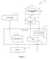
- FIG. 2shows a block diagram of a system to graphically navigate hierarchical data groups, according to one exemplary embodiment of the present invention.
- FIG. 3is a flowchart illustrating operations performed to graphically navigate hierarchical data groups in accordance with an embodiment of the present invention.
- FIGS. 4A-4Dshow a network performance management console to graphically navigate hierarchical business groups, according to one exemplary embodiment of the present invention.
- FIG. 5shows a diagrammatic representation of a machine in the exemplary form of a computer system within which a set of instructions for causing the machine to perform a program configured in accordance with an embodiment of the present invention may be executed.
- Network traffic data regarding a number of network nodesmay be collected for individual network nodes, as well as for groups or collections of network nodes.
- network nodesmay be combined into logical groupings (e.g., business groups) according to their IP addresses.
- a business group of network nodesmay include one or more IP addresses or one or more ranges of IP addresses.
- Business groupscan also be allocated to business group containers.
- a usermay designate one or more business groups to be included in a container. For example, “CA” and “FL” business groups may be defined as members of the “US” container.
- a business group(e.g., “CA”) may itself be designated as a container and include its own member business groups, such as “SFO”, “SJC,” and “LAX.”
- business groups and containersmay be organized in a hierarchy (e.g. US->CA->SFO), which may be referred to as a BG container hierarchy.
- a BG container hierarchymay be defined by a user, stored in a database, and managed via a user interface (referred to as the management console).
- Network traffic and performance datamay be collected by an appliance configured for such purpose.
- Network traffic between business groups and between containersmay be derived from traffic between their respective member business groups.
- traffic between containers CA and FLmay be derived from traffic between CA member business groups (e.g., LAX, SFO, and SJC) and FL member business groups (e.g., MIA, TPA, and ORL).
- Traffic flows between business groups and between containersmay be stored in a database as both the relationship between the containers themselves and the relationship between the source container and the members of the destination container (e.g. for traffic between CA and FL the database may store relationships between CA and FL, between CA and MIA, TPA and ORL, and so on).
- a management consolemay be configured to display data flows between individual BGs in the form of a visual (e.g., graphical) network.
- a management consolemay be utilized to display derived flows between business group containers.
- a network topology navigation toolmay be provided to interrogate the database storing relationships between business groups and to retrieve network traffic (e.g., data flow) information for the particular business group.
- network traffice.g., data flow
- an interrogation of the databasemay return all business groups and containers that have network traffic with the selected business group regardless of their position in the hierarchy, which may include information redundant or not directly relevant to the user's request.
- a more intelligent network topology navigation toolmay be configured to retrieve only such database entries that are relevant to the selected business group and the selected hierarchy level and, at the same time, to enable the user to access more detailed connection information (e.g., connections to individual members of relevant business groups) by moving down through the hierarchy (i.e., through appropriate drill-downs).
- more detailed connection informatione.g., connections to individual members of relevant business groups
- FIG. 1Ashows a diagrammatic representation of an exemplary group of networked nodes connected to a network.
- Lines between entitiesare network links, which may be any mode of establishing a connection between nodes including wired and/or wireless connections.
- a firewall 10surrounds a geographic collection of networked nodes and separates the internal network from the external network.
- a network traffic monitoring device 12is shown at the firewall.
- the network traffic monitoring device 12may be located within the internal network, or on the external network or anywhere that allows the method of the present invention to be practiced.
- entity 12need not be “inline.” That is, traffic need not necessarily pass through entity 12 in order to pass from the server to the client and vice versa.
- the entity 12can be a passive monitoring device, e.g., spanning a switch or router, whereby all the traffic is copied to a switch span port which passes traffic to entity 12 .
- a modern networkmay include multiple logical groups (e.g., business groups BG 1 and BG 2 ) of nodes.
- Logical groupsmay be business groups, computers performing the same function, computers located within the same building, or any other logical groupings.
- FIG. 1Ashows one simple organization of a small number of computers and other network nodes, but those skilled in the art will appreciate that the number of computers and network nodes may be significantly larger as can the number of connections between them.
- BG 1contains several internal network nodes N 101 , N 102 , N 103 , and N 104 and external nodes N 105 , N 106 and N 107 .
- BG 2contains several internal network nodes N 201 , N 202 , N 203 , N 204 , N 205 , N 206 .
- a network nodemay be any computer or device on the network that communicates with other computers or devices on the network.
- Each nodemay function as a client, server, or both.
- node N 103is shown as a database which is connected to Node N 104 , a web application server, via a network link 2 .
- N 104is also depicted as connected to the external network via network link 28 .
- N 104is typically for N 104 to function as a server, which returns results in response to requests from the external network.
- database node N 103which functions as a server to N 104 , is shown connected to node N 107 via a network link 4 .
- N 107may upload information to the database via link 4 , whereby N 107 is functioning as a server and N 103 is functioning as a client. However, N 107 is also shown connected to the external network via link 26 . This link could indicate that N 107 is browsing the Internet and functioning as a client.
- network nodesneed not be within the internal network in order to belong to a logical group.
- traveling employeesmay connect to the logical group network via a Virtual Private Network (VPN) or via ordinary network transport protocols through an external network such as the Internet.
- VPNVirtual Private Network
- network nodes N 105 , N 106 , N 107belong to logical group BG 1 , but are outside the firewall, and may be geographically distant from the other network nodes in BG 1 .
- network nodes N 207 , N 208 , N 209 , N 210 , N 211are members of logical group BG 2 , but are physically removed from the other members of BG 2 .
- firewall in this configurationis for illustrative purposes only and is not a required element in networks where the present invention may be practiced.
- the separation between internal and external nodes of a networkmay also be formed by geographic distance, or by networking paths (that may be disparate or require many hops for the nodes to connect to one another regardless of the geographic proximity).
- FIG. 1Bshows a diagrammatic representation of network links between logical groups BG 1 , BG 2 and the external network. While in FIG. 1A , nodes N 101 , N 104 , N 105 , and N 107 are depicted as connected to the external network via network links 22 , 24 , 26 , and 28 , in FIG. 1B , the traffic over multiple links 22 , 24 , 26 , 28 to the external network is condensed into one virtual link containing all inbound and outbound traffic 20 between the logical group BG 1 and the external network. A similar condensation of network traffic is depicted in the views of BG 2 in FIG. 1A and in FIG. 1B . In FIG.
- FIG. 1Asix links 42 , 43 , 45 , 46 , 47 , 48 between the external network and the logical group BG 2 are depicted.
- FIG. 1Ball links between BG 2 and the external network are condensed into one virtual link 40 over which the aggregate traffic network metrics for the logical group may be viewed.
- FIG. 1Balso shows the condensation of multiple links 32 , 34 , 36 between logical groups BG 1 , BG 2 into one virtual link 30 over which aggregate network traffic between logical groups may be viewed and analyzed.
- the total network traffic datamay be presented by protocol, by port, by application, or by member-connected IP address per logical group. In this latter case, the total network traffic data is presented, for each logical group, by any or all of a logical group member IP address, a logical group connected IP address, a logical group member and then a logical group connected IP address, and a logical group connected and then a logical group member IP address.
- the total network traffic datamay be presented by member-connected IP address per logical application sub-group, by member-connected IP address per logical group-to-group connection, by member-connected IP address per logical application group-to-group connection, by member-connected IP address per logical port sub-group, in a role-based fashion for the IP addresses, and/or from a standpoint of a common reference point.
- FIG. 2shows block diagram of a system 50 to graphically navigate hierarchical data groups, according to one exemplary embodiment of the present invention.
- a topology tool 52 of the system 50enables a network management console to display data flows between business groups of network nodes (BGs) in the form of a visual network.
- the topology tool 52receives user selection of one or more business groups (i.e., a selection of graphical representation of one or more business groups) via an extractor 54 .
- the topology tool 52may provide a tree navigator 56 , which allows the user to graphically navigate a BG container hierarchy in order select graphical representation of one or more business groups of interest.
- a selected BGmay be a BG having one or more members (which may be referred to as a BG container), no members (which may be referred to as a leaf node), or being itself a member of another BG container.
- the graphical representation of BG container hierarchy that is presented to the usermay be obtained from a business group tree manager 58 .
- the topology tool 52may access network performance data for BGs in the BG container hierarchy stored in a network traffic database 60 .
- the entries in the network traffic database 60are created utilizing a network performance collector 62 (e.g., a network monitoring device such as the network traffic monitoring device 12 of FIGS. 1A-1B ).
- the system 50may be, in one embodiment, a stand-alone device, a software application, or it may be incorporated into a network management console responsible for a variety of tasks related to network monitoring.
- the topology tool 52accesses the network traffic database 60 to identify BGs connected to the selected BGs and utilizes a filter 64 to retrieve only such BGs that are relevant pursuant to predetermined rules.
- the resulting visual network displayed to the usermay include traffic flows indicators as well as any of the metrics available via the network management console, e.g., throughput data for some or all pairs of connected BGs.
- the topology tool 52filters connected groups according to the following rules:
- BGshares a common parent with the selected BG and is at the same level in the hierarchy as the selected BG, the BG is displayed by the topology tool 52 , otherwise it is not displayed. If there is any traffic between these groups, they will be linked in the visual network topology presented to the user.
- BGits top-level container
- a connected BGis not a member of any BG container, then it is displayed. If there is any traffic between the BG and other displayed BGs, then the BG will be shown as connected to the other BGs in the visual network topology.
- the topology tool 52utilizes the filter 64 such that only BGs that are determined to be relevant to the user's selection are displayed.
- the traffic flows between the selected groups and other BGs in the hierarchymay be automatically discovered by the topology tool 52 from the network traffic database 60 entries.
- the usercan also turn the auto-discover feature off, in which case only the selected BGs and traffic flows between the selected BGs are shown.
- the system 50may further include a drill-down component 66 to enable a user to view more detailed information related a particular BG (e.g. the members of a BG).
- the drill-down component 66may be provided by the topology tool 52 .
- the usercan drill-down on any displayed BG (e.g., by double-clicking on a BG of interest or by selecting a menu option from a right-click popup menu), which causes the BGs in the next level down in the hierarchy to be displayed along with the BGs that they have traffic with.
- FIG. 3shows a flowchart illustrating method 70 to graphically navigate hierarchical data groups, according to one exemplary embodiment of the present invention.
- the topology tool 52receives a request from a user to retrieve network traffic information relating to connected business groups, containers, or nodes that are relevant to one or more selected business groups. It will be noted, that because a business group may be a member of a container having a higher level of hierarchy and at the same time itself contain members having a lower level of hierarchy, a reference to a business group includes a reference to a container.
- the topology tool 52interrogates the traffic database and retrieves network traffic information relating to connected business groups according to predefined rules at operation 76 .
- the predetermined rulesmay include, for example, the rules described with reference to FIG. 3 , where the topology tool 52 graphically shows only BG containers at the selected level of the hierarchy.
- the topology tool 52displays network traffic information for the retrieved BGs to the user at operation 78 , as shown in FIGS. 4A-4D .
- FIGS. 4A-4Dillustrate a network performance management console 90 to graphically navigate hierarchical business groups, according to one embodiment of the present invention.
- the user interfaceincludes a business group (BG) hierarchy area 92 , a graphical navigation area 94 , a topology drawing area 96 , and a tabular representation area 98 .
- BGbusiness group
- a useris permitted to explore a business group container hierarchy within the BG hierarchy area 92 and select one or more BGs. Responsive to a user selection and a command to convey to the system 50 that the user is seeking network performance information regarding the selected BGs, the user is permitted to graphically navigate the selected portions of the hierarchy displayed within the graphical navigation area 94 .
- the usermay also be presented with a topology drawing of the connections for the selected BGs in the topology drawing area 96 .
- a usermay also be provided with a tabular representation of the network traffic data for the selected BGs in the tabular representation area 98 .
- the topology tool 52displays “US” container connected to “Europe.” “Europe” container is at the same level of hierarchy as “US.” The topology tool 52 also displays a connection between “US” and “Other Group” in the graphical navigation area 94 . “Other Group” itself is not a member of any BG container and, in one embodiment, is displayed regardless of its level of hierarchy.
- an auto discover control 102is engaged (e.g., a corresponding checkbox is checked), which instructs the topology tool 52 to display BGs connected to the selected BG (here, a container), rather than displaying the selected BGs only.
- a useris presented graphically with connections to the selected BG, “US.”
- a usermay wish to further explore the connections within one of the displayed containers. For example, a user may wish to see which members of the “Europe” container are connected to “US” container.
- a usermay be permitted to drill down to one or more displayed BG containers in order to view a more detailed graphical representation of the visual network topology.
- a usermay be permitted to select an appropriate drilldown mode from several illustrative drilldown modes provided by the drilldown component 66 of the topology tool 52 . Some of the exemplary drilldown modes are described below.
- This drilldown modewhen a user selects a BG container for drilldown, all the direct members of the selected BG container are discovered and each member of the selected BG container is displayed and as a node in the graphical navigation area 94 . If any of these discovered members have network traffic between them, then the links and the traffic between such nodes are discovered and displayed.
- the member discovery drilldown modemay be utilized when a user wishes to “zoom” into a visual representation of a particular BG container in order to view and understand interconnectivity between its members.
- FIG. 4Bshows graphical representation of network topology presented to the user when the user drills down into “Europe” container utilizing the member discovery mode.
- FIG. 4Bwhen “Europe” is expanded, individual members of “Europe” (here, “FR,” “IT,” “UK,” and “DE”) are graphically presented to the user.
- a request to drill downmay be made by a user by, for example, clicking or double clicking on the container or BG of interest (which may be designated to correspond to a default drilldown mode) or by selecting a drilldown mode from a pull-down menu 104 or a hover menu that may be presented to the user (e.g., responsive to a right click by the user).
- Full member to connected groups discoveryin this mode, when a user selects a BG container for drilldown, all the direct members of the selected BG container are discovered and each member of the selected BG container is displayed and as a node in the graphical navigation area 94 together with the links between them, similar to the member discovery mode. In addition, if any of these discovered members have network traffic between them and any of the other nodes that are not members of the selected BG container, then the links and the traffic between such nodes are discovered and displayed. These other nodes may include any of the nodes displayed in the original topology (i.e. prior to the drilldown action), as well as additional nodes that were not displayed in the original topology but have traffic to the member nodes of the selected BG container.
- the additional nodesare either top level BG containers or leaf nodes.
- This drilldown modemay be utilized when a user wishes to “zoom” into a visual representation of a particular BG container as well as “zoom” into the links between the selected BG container and any of its connected BGs. In one embodiment of the present invention, this is the broadest form of drilldown link discovery.
- the full member to connected groups discovery modeis illustrated in FIG. 4C .
- a drilldown into “Europe”presents the user not only with the members of “Europe” and the connection between the members, but also with connections between members of “Europe” and any other BGs or BG containers outside of “Europe.
- this drilldown modeallows the user to see that “IT” and “DE” both have network traffic with “Asia.”
- the drilldown component 66 of the topology tool 52may provide a limited member to connected groups discovery mode.
- Limited member to connected groups discoveryin this mode, all the members of the selected BG container are discovered. However, only those member BGs are displayed in graphical navigation area 94 that have network traffic with any of the originally displayed nodes. The links between the selected BG container and the other displayed nodes are replaced with links between the members of the selected BG container and those same other displayed nodes where there is network traffic between the nodes. In this mode, any links between the members of the selected BG container and BGs that were not originally displayed in graphical navigation area 94 are not presented to the user. For example, in this mode, the connection between “DE” and “Asia” is not displayed.
- the useris permitted to drilldown into the link to a particular BG container, e.g., the link between “US” and “Europe,” to discover how much of the traffic between “US” and “Europe” is, for example, from traffic between “UK” and “US.”
- a particular BG containere.g., the link between “US” and “Europe”
- “Europe” containerhas traffic with “Asia”
- the usermay be only interested in understanding more about the link between “US” and “Europe,” and therefore no links to Asia is shown in this mode.
- FIG. 4Dillustrates the limited member to connected groups discovery drilldown mode.
- the userselected “US” in the BG hierarchy area 92 and requested a limited discovery drilldown on “Europe.”
- the useris presented only with connections between the members of “Europe” and the originally selected “US” container.
- FIG. 5shows a diagrammatic representation of a machine in the exemplary form of a computer system 400 within which a set of instructions, for causing the machine to perform a program configured in accordance with an embodiment of the present invention.
- the machineoperates as a standalone device or may be connected (e.g., networked) to other machines, in which case it may be a node in the network.
- the machinemay operate in the capacity of a server or a client machine in a server-client network environment, or as a peer machine in a peer-to-peer (or distributed) network environment.
- the machinemay be a server computer, a client computer, a personal computer (PC), a tablet PC, a set-top box (STB), a Personal Digital Assistant (PDA), a cellular telephone, a web appliance, a network router, switch or bridge, or any machine capable of executing a set of instructions (sequential or otherwise) that specify actions to be taken by that machine.
- PCpersonal computer
- PDAPersonal Digital Assistant
- STBset-top box
- a cellular telephonea web appliance
- network routerswitch or bridge
- the exemplary computer system 400includes a processor 402 (e.g., a central processing unit (CPU) a graphics processing unit (GPU) or both), a main memory 404 and a static memory 406 , which communicate with each other via a bus 408 .
- the computer system 400may further include a video display unit 410 (e.g., a liquid crystal display (LCD) or a cathode ray tube (CRT)).
- the computer system 400also includes an alphanumeric input device 412 (e.g., a keyboard), a cursor control device 414 (e.g., a mouse), a disk drive unit 416 , a signal generation device 418 (e.g., a speaker) and a network interface device 420 .
- the disk drive unit 416includes a machine-readable medium 422 on which is stored one or more sets of instructions (e.g., software) 424 embodying any one or more of the methodologies or functions described herein.
- the software 424may also reside, completely or at least partially, within the main memory 404 and/or within the processor 402 during execution thereof by the computer system 400 , the main memory 404 and the processor 402 also constituting machine-readable media.
- the software 424may further be transmitted or received over a network 426 via the network interface device 420 .
- machine-readable medium 422is shown in an exemplary embodiment to be a single medium, the term “machine-readable medium” should be taken to include a single medium or multiple media (e.g., a centralized or distributed database, and/or associated caches and servers) that store the one or more sets of instructions.
- the term “machine-readable medium”shall also be taken to include any medium that is capable of storing, encoding or carrying a set of instructions for execution by the machine and that cause the machine to perform any one or more of the methodologies of the present invention.
- the term “machine-readable medium”shall accordingly be taken to include, but not be limited to, solid-state memories, optical and magnetic media, and carrier wave signals.
Landscapes
- Engineering & Computer Science (AREA)
- Databases & Information Systems (AREA)
- Theoretical Computer Science (AREA)
- Computer Networks & Wireless Communication (AREA)
- Signal Processing (AREA)
- Data Mining & Analysis (AREA)
- Physics & Mathematics (AREA)
- General Engineering & Computer Science (AREA)
- General Physics & Mathematics (AREA)
- Human Computer Interaction (AREA)
- Software Systems (AREA)
- Data Exchanges In Wide-Area Networks (AREA)
Abstract
Description
Claims (32)
Priority Applications (1)
| Application Number | Priority Date | Filing Date | Title |
|---|---|---|---|
| US12/397,356US7885206B2 (en) | 2005-02-18 | 2009-03-04 | Method and system for topological navigation of hierarchical data groups |
Applications Claiming Priority (2)
| Application Number | Priority Date | Filing Date | Title |
|---|---|---|---|
| US11/061,978US7519700B1 (en) | 2005-02-18 | 2005-02-18 | Method and system for topological navigation of hierarchical data groups |
| US12/397,356US7885206B2 (en) | 2005-02-18 | 2009-03-04 | Method and system for topological navigation of hierarchical data groups |
Related Parent Applications (1)
| Application Number | Title | Priority Date | Filing Date |
|---|---|---|---|
| US11/061,978ContinuationUS7519700B1 (en) | 2005-02-18 | 2005-02-18 | Method and system for topological navigation of hierarchical data groups |
Publications (2)
| Publication Number | Publication Date |
|---|---|
| US20090245138A1 US20090245138A1 (en) | 2009-10-01 |
| US7885206B2true US7885206B2 (en) | 2011-02-08 |
Family
ID=40525222
Family Applications (2)
| Application Number | Title | Priority Date | Filing Date |
|---|---|---|---|
| US11/061,978Active2027-04-29US7519700B1 (en) | 2005-02-18 | 2005-02-18 | Method and system for topological navigation of hierarchical data groups |
| US12/397,356Expired - LifetimeUS7885206B2 (en) | 2005-02-18 | 2009-03-04 | Method and system for topological navigation of hierarchical data groups |
Family Applications Before (1)
| Application Number | Title | Priority Date | Filing Date |
|---|---|---|---|
| US11/061,978Active2027-04-29US7519700B1 (en) | 2005-02-18 | 2005-02-18 | Method and system for topological navigation of hierarchical data groups |
Country Status (1)
| Country | Link |
|---|---|
| US (2) | US7519700B1 (en) |
Cited By (5)
| Publication number | Priority date | Publication date | Assignee | Title |
|---|---|---|---|---|
| US20070097883A1 (en)* | 2005-08-19 | 2007-05-03 | Yigong Liu | Generation of a network topology hierarchy |
| US8694918B2 (en) | 2012-02-06 | 2014-04-08 | International Business Machines Corporation | Conveying hierarchical elements of a user interface |
| US20150310022A1 (en)* | 2011-07-11 | 2015-10-29 | International Business Machines Corporation | Searching documentation across interconnected nodes in a distributed network |
| US9514027B2 (en) | 2011-11-08 | 2016-12-06 | Microsoft Technology Licensing, Llc | Context-aware model-driven hierarchical monitoring metadata |
| US10778537B1 (en)* | 2019-02-19 | 2020-09-15 | Cisco Technology, Inc. | Presenting devices from an aggregated node within a network topology |
Families Citing this family (80)
| Publication number | Priority date | Publication date | Assignee | Title |
|---|---|---|---|---|
| US8914726B2 (en)* | 2005-08-20 | 2014-12-16 | Riverbed Technology, Inc. | Visualizing a complex network based on a set of objects of interest |
| US8000318B2 (en)* | 2006-06-30 | 2011-08-16 | Embarq Holdings Company, Llc | System and method for call routing based on transmission performance of a packet network |
| US8194643B2 (en) | 2006-10-19 | 2012-06-05 | Embarq Holdings Company, Llc | System and method for monitoring the connection of an end-user to a remote network |
| US8289965B2 (en) | 2006-10-19 | 2012-10-16 | Embarq Holdings Company, Llc | System and method for establishing a communications session with an end-user based on the state of a network connection |
| US7948909B2 (en) | 2006-06-30 | 2011-05-24 | Embarq Holdings Company, Llc | System and method for resetting counters counting network performance information at network communications devices on a packet network |
| US9094257B2 (en) | 2006-06-30 | 2015-07-28 | Centurylink Intellectual Property Llc | System and method for selecting a content delivery network |
| US8488447B2 (en) | 2006-06-30 | 2013-07-16 | Centurylink Intellectual Property Llc | System and method for adjusting code speed in a transmission path during call set-up due to reduced transmission performance |
| US7765294B2 (en) | 2006-06-30 | 2010-07-27 | Embarq Holdings Company, Llc | System and method for managing subscriber usage of a communications network |
| US8717911B2 (en) | 2006-06-30 | 2014-05-06 | Centurylink Intellectual Property Llc | System and method for collecting network performance information |
| US7843831B2 (en) | 2006-08-22 | 2010-11-30 | Embarq Holdings Company Llc | System and method for routing data on a packet network |
| US8040811B2 (en) | 2006-08-22 | 2011-10-18 | Embarq Holdings Company, Llc | System and method for collecting and managing network performance information |
| US8224255B2 (en) | 2006-08-22 | 2012-07-17 | Embarq Holdings Company, Llc | System and method for managing radio frequency windows |
| US7684332B2 (en) | 2006-08-22 | 2010-03-23 | Embarq Holdings Company, Llc | System and method for adjusting the window size of a TCP packet through network elements |
| US8125897B2 (en) | 2006-08-22 | 2012-02-28 | Embarq Holdings Company Lp | System and method for monitoring and optimizing network performance with user datagram protocol network performance information packets |
| US8743703B2 (en) | 2006-08-22 | 2014-06-03 | Centurylink Intellectual Property Llc | System and method for tracking application resource usage |
| US8549405B2 (en) | 2006-08-22 | 2013-10-01 | Centurylink Intellectual Property Llc | System and method for displaying a graphical representation of a network to identify nodes and node segments on the network that are not operating normally |
| US8144587B2 (en) | 2006-08-22 | 2012-03-27 | Embarq Holdings Company, Llc | System and method for load balancing network resources using a connection admission control engine |
| US8199653B2 (en) | 2006-08-22 | 2012-06-12 | Embarq Holdings Company, Llc | System and method for communicating network performance information over a packet network |
| US8194555B2 (en) | 2006-08-22 | 2012-06-05 | Embarq Holdings Company, Llc | System and method for using distributed network performance information tables to manage network communications |
| US8130793B2 (en) | 2006-08-22 | 2012-03-06 | Embarq Holdings Company, Llc | System and method for enabling reciprocal billing for different types of communications over a packet network |
| US8144586B2 (en) | 2006-08-22 | 2012-03-27 | Embarq Holdings Company, Llc | System and method for controlling network bandwidth with a connection admission control engine |
| US8238253B2 (en) | 2006-08-22 | 2012-08-07 | Embarq Holdings Company, Llc | System and method for monitoring interlayer devices and optimizing network performance |
| US8750158B2 (en) | 2006-08-22 | 2014-06-10 | Centurylink Intellectual Property Llc | System and method for differentiated billing |
| US8531954B2 (en) | 2006-08-22 | 2013-09-10 | Centurylink Intellectual Property Llc | System and method for handling reservation requests with a connection admission control engine |
| US8189468B2 (en) | 2006-10-25 | 2012-05-29 | Embarq Holdings, Company, LLC | System and method for regulating messages between networks |
| US8228791B2 (en) | 2006-08-22 | 2012-07-24 | Embarq Holdings Company, Llc | System and method for routing communications between packet networks based on intercarrier agreements |
| US8102770B2 (en) | 2006-08-22 | 2012-01-24 | Embarq Holdings Company, LP | System and method for monitoring and optimizing network performance with vector performance tables and engines |
| US8407765B2 (en)* | 2006-08-22 | 2013-03-26 | Centurylink Intellectual Property Llc | System and method for restricting access to network performance information tables |
| US8619600B2 (en) | 2006-08-22 | 2013-12-31 | Centurylink Intellectual Property Llc | System and method for establishing calls over a call path having best path metrics |
| US8576722B2 (en) | 2006-08-22 | 2013-11-05 | Centurylink Intellectual Property Llc | System and method for modifying connectivity fault management packets |
| US9479341B2 (en) | 2006-08-22 | 2016-10-25 | Centurylink Intellectual Property Llc | System and method for initiating diagnostics on a packet network node |
| US8274905B2 (en) | 2006-08-22 | 2012-09-25 | Embarq Holdings Company, Llc | System and method for displaying a graph representative of network performance over a time period |
| US7940735B2 (en)* | 2006-08-22 | 2011-05-10 | Embarq Holdings Company, Llc | System and method for selecting an access point |
| US8098579B2 (en)* | 2006-08-22 | 2012-01-17 | Embarq Holdings Company, LP | System and method for adjusting the window size of a TCP packet through remote network elements |
| US8307065B2 (en) | 2006-08-22 | 2012-11-06 | Centurylink Intellectual Property Llc | System and method for remotely controlling network operators |
| US8537695B2 (en) | 2006-08-22 | 2013-09-17 | Centurylink Intellectual Property Llc | System and method for establishing a call being received by a trunk on a packet network |
| US8107366B2 (en)* | 2006-08-22 | 2012-01-31 | Embarq Holdings Company, LP | System and method for using centralized network performance tables to manage network communications |
| US8064391B2 (en) | 2006-08-22 | 2011-11-22 | Embarq Holdings Company, Llc | System and method for monitoring and optimizing network performance to a wireless device |
| US8223655B2 (en) | 2006-08-22 | 2012-07-17 | Embarq Holdings Company, Llc | System and method for provisioning resources of a packet network based on collected network performance information |
| US8015294B2 (en) | 2006-08-22 | 2011-09-06 | Embarq Holdings Company, LP | Pin-hole firewall for communicating data packets on a packet network |
| US8032926B2 (en)* | 2006-12-06 | 2011-10-04 | Electronics And Telecommunications Research Institute | Method of configuring hierarchical network of user group and resource group and key distribution center |
| US10080107B2 (en) | 2007-04-30 | 2018-09-18 | Intech 21, Inc. | Topographical display generator for ad hoc network |
| US8621360B2 (en)* | 2007-04-30 | 2013-12-31 | Intech 21, Inc. | Topographical display generator for AD HOC network |
| US8111692B2 (en) | 2007-05-31 | 2012-02-07 | Embarq Holdings Company Llc | System and method for modifying network traffic |
| US7730179B2 (en)* | 2007-06-26 | 2010-06-01 | Novell, Inc. | System and method for policy-based registration of client devices |
| US20090251407A1 (en)* | 2008-04-03 | 2009-10-08 | Microsoft Corporation | Device interaction with combination of rings |
| US8068425B2 (en) | 2008-04-09 | 2011-11-29 | Embarq Holdings Company, Llc | System and method for using network performance information to determine improved measures of path states |
| US20090289937A1 (en)* | 2008-05-22 | 2009-11-26 | Microsoft Corporation | Multi-scale navigational visualtization |
| US20090319940A1 (en)* | 2008-06-20 | 2009-12-24 | Microsoft Corporation | Network of trust as married to multi-scale |
| US8682736B2 (en)* | 2008-06-24 | 2014-03-25 | Microsoft Corporation | Collection represents combined intent |
| US20100199223A1 (en)* | 2009-02-03 | 2010-08-05 | Oracle International Corporation | Hierarchy display |
| DE102009012164A1 (en)* | 2009-03-06 | 2010-09-09 | Siemens Aktiengesellschaft | Method for selecting a communication system assigned to a transmission network of an automation system |
| US8488490B2 (en)* | 2009-10-14 | 2013-07-16 | At&T Intellectual Property I, L.P. | Methods and apparatus to determine a capacity for a network layer topology |
| EP2362577A1 (en)* | 2010-02-23 | 2011-08-31 | ABB Technology AG | Analysing communication configuration in a process control system |
| US8849924B2 (en)* | 2010-04-08 | 2014-09-30 | Microsoft Corporation | Network infrastructure management |
| US9077623B2 (en)* | 2010-12-13 | 2015-07-07 | Microsoft Technology Licensing, Llc | Network management system supporting customizable groups |
| WO2012103665A1 (en) | 2011-01-31 | 2012-08-09 | Hewlett-Packard Development Company, L.P. | Methods and systems to generate reports including report references for navigation |
| US9160630B2 (en)* | 2011-06-07 | 2015-10-13 | Vmware, Inc. | Network connectivity and security visualization |
| US20150089374A1 (en)* | 2013-09-20 | 2015-03-26 | Cyan Inc. | Network visualization system and method |
| WO2015056052A1 (en)* | 2013-10-16 | 2015-04-23 | Pismo Labs Technology Limited | Methods and systems for displaying network performance information |
| JP2015165636A (en)* | 2014-03-03 | 2015-09-17 | 株式会社日立製作所 | Detecting device, detecting method, and detecting program |
| US9647909B2 (en)* | 2014-09-23 | 2017-05-09 | Uila Networks, Inc. | Monitor a data center infrastructure |
| JP6428442B2 (en)* | 2015-03-31 | 2018-11-28 | 富士通株式会社 | Display method, display program, and information processing apparatus |
| US10156842B2 (en) | 2015-12-31 | 2018-12-18 | General Electric Company | Device enrollment in a cloud service using an authenticated application |
| US10367703B2 (en)* | 2016-12-01 | 2019-07-30 | Gigamon Inc. | Analysis of network traffic rules at a network visibility node |
| US20180205611A1 (en)* | 2017-01-13 | 2018-07-19 | Gigamon Inc. | Network enumeration at a network visibility node |
| US10805239B2 (en) | 2017-03-07 | 2020-10-13 | Nicira, Inc. | Visualization of path between logical network endpoints |
| US10673714B1 (en)* | 2017-03-29 | 2020-06-02 | Juniper Networks, Inc. | Network dashboard with multifaceted utilization visualizations |
| US10931539B2 (en) | 2018-12-21 | 2021-02-23 | Cisco Technology, Inc. | Graphical user interface for displaying a network traffic route in a single-view display |
| US11032154B2 (en)* | 2018-12-21 | 2021-06-08 | Cisco Technology, Inc. | Graphical user interface for displaying a hierarchical network topology in a single site view |
| US11283699B2 (en) | 2020-01-17 | 2022-03-22 | Vmware, Inc. | Practical overlay network latency measurement in datacenter |
| US11196628B1 (en) | 2020-07-29 | 2021-12-07 | Vmware, Inc. | Monitoring container clusters |
| US11570090B2 (en) | 2020-07-29 | 2023-01-31 | Vmware, Inc. | Flow tracing operation in container cluster |
| US11558426B2 (en) | 2020-07-29 | 2023-01-17 | Vmware, Inc. | Connection tracking for container cluster |
| CN114697319B (en)* | 2020-12-30 | 2023-06-16 | 华为云计算技术有限公司 | Tenant service management method and device for public cloud |
| US11736436B2 (en) | 2020-12-31 | 2023-08-22 | Vmware, Inc. | Identifying routes with indirect addressing in a datacenter |
| US11336533B1 (en)* | 2021-01-08 | 2022-05-17 | Vmware, Inc. | Network visualization of correlations between logical elements and associated physical elements |
| US11687210B2 (en) | 2021-07-05 | 2023-06-27 | Vmware, Inc. | Criteria-based expansion of group nodes in a network topology visualization |
| US11711278B2 (en) | 2021-07-24 | 2023-07-25 | Vmware, Inc. | Visualization of flow trace operation across multiple sites |
| US11706109B2 (en) | 2021-09-17 | 2023-07-18 | Vmware, Inc. | Performance of traffic monitoring actions |
Citations (15)
| Publication number | Priority date | Publication date | Assignee | Title |
|---|---|---|---|---|
| US5805819A (en)* | 1995-04-24 | 1998-09-08 | Bay Networks, Inc. | Method and apparatus for generating a display based on logical groupings of network entities |
| US6137782A (en)* | 1998-07-21 | 2000-10-24 | Sharon; Azulai | Automatic network traffic analysis |
| US6259679B1 (en) | 1996-02-22 | 2001-07-10 | Mci Communications Corporation | Network management system |
| US6363319B1 (en)* | 1999-08-31 | 2002-03-26 | Nortel Networks Limited | Constraint-based route selection using biased cost |
| US20030046390A1 (en)* | 2000-05-05 | 2003-03-06 | Scott Ball | Systems and methods for construction multi-layer topological models of computer networks |
| US20040085961A1 (en)* | 2002-11-01 | 2004-05-06 | John Coffell | Method for advertising reachable address information in a network |
| US6801496B1 (en)* | 1999-01-15 | 2004-10-05 | Cisco Technology, Inc. | Network addressing scheme for reducing protocol overhead in an optical network |
| US20040228331A1 (en)* | 2001-09-03 | 2004-11-18 | Hansen Per Flemming | Telecommunications network |
| US6850486B2 (en)* | 1999-01-15 | 2005-02-01 | Cisco Technology, Inc. | Method of reducing traffic during path restoration |
| US20050050225A1 (en)* | 2003-08-29 | 2005-03-03 | Tatman Lance A. | System and method for discovery of BGP router topology |
| US6973023B1 (en)* | 2000-12-30 | 2005-12-06 | Cisco Technology, Inc. | Method for routing information over a network employing centralized control |
| US20060126534A1 (en)* | 2004-12-10 | 2006-06-15 | Huibregtse Thomas P | Method and mechanism for identifying an unmanaged switch in a network |
| US7372806B2 (en)* | 2001-10-31 | 2008-05-13 | Nec Corporation | Fault recovery system and method for a communications network |
| US7636335B2 (en)* | 2003-12-22 | 2009-12-22 | Telefonaktiebolaget Lm Ericsson (Publ) | Arrangements and method for handling macro diversity in a universal mobile telecommunications system |
| US7649834B2 (en)* | 2004-09-15 | 2010-01-19 | At&T Intellectual Property Ii, L.P. | Method and apparatus for determining neighboring routing elements and rerouting traffic in a computer network |
Family Cites Families (11)
| Publication number | Priority date | Publication date | Assignee | Title |
|---|---|---|---|---|
| US5821937A (en)* | 1996-02-23 | 1998-10-13 | Netsuite Development, L.P. | Computer method for updating a network design |
| US6393472B1 (en)* | 1997-12-10 | 2002-05-21 | At&T Corp. | Automatic aggregation of network management information in spatial, temporal and functional forms |
| US6407751B1 (en)* | 1998-01-28 | 2002-06-18 | International Business Machines Corporation | Method and apparatus of generating mobile objects and storage medium storing an object generating mobile objects |
| US6259670B1 (en)* | 1998-07-17 | 2001-07-10 | Seagate Technology Llc | Magneto-optical preamplifier |
| US6697087B1 (en)* | 1999-05-05 | 2004-02-24 | Microsoft Corporation | Updating diagrams of dynamic representational Models of dynamic systems |
| EP1212686A4 (en)* | 1999-05-26 | 2009-04-01 | Fujitsu Ltd | ADMINISTRATION SYSTEM FOR NETWORK ELEMENTS |
| US6727927B1 (en)* | 2000-03-08 | 2004-04-27 | Accenture Llp | System, method and article of manufacture for a user interface for a knowledge management tool |
| US20040015579A1 (en)* | 2001-06-14 | 2004-01-22 | Geoffrey Cooper | Method and apparatus for enterprise management |
| US7310666B2 (en)* | 2001-06-29 | 2007-12-18 | International Business Machines Corporation | Method and system for restricting and enhancing topology displays for multi-customer logical networks within a network management system |
| US8745198B2 (en)* | 2004-09-10 | 2014-06-03 | Riverbad Technology, Inc. | Method for discovery and troubleshooting of network application usage and performance issues |
| US7327998B2 (en)* | 2004-12-22 | 2008-02-05 | Elster Electricity, Llc | System and method of providing a geographic view of nodes in a wireless network |
- 2005
- 2005-02-18USUS11/061,978patent/US7519700B1/enactiveActive
- 2009
- 2009-03-04USUS12/397,356patent/US7885206B2/ennot_activeExpired - Lifetime
Patent Citations (19)
| Publication number | Priority date | Publication date | Assignee | Title |
|---|---|---|---|---|
| US5805819A (en)* | 1995-04-24 | 1998-09-08 | Bay Networks, Inc. | Method and apparatus for generating a display based on logical groupings of network entities |
| US6259679B1 (en) | 1996-02-22 | 2001-07-10 | Mci Communications Corporation | Network management system |
| US6137782A (en)* | 1998-07-21 | 2000-10-24 | Sharon; Azulai | Automatic network traffic analysis |
| US7002917B1 (en)* | 1999-01-15 | 2006-02-21 | Cisco Technology, Inc. | Method for path selection in a network |
| US7724655B2 (en)* | 1999-01-15 | 2010-05-25 | Cisco Systems, Inc. | Network addressing scheme for reducing protocol overhead in an optical network |
| US6801496B1 (en)* | 1999-01-15 | 2004-10-05 | Cisco Technology, Inc. | Network addressing scheme for reducing protocol overhead in an optical network |
| US6850486B2 (en)* | 1999-01-15 | 2005-02-01 | Cisco Technology, Inc. | Method of reducing traffic during path restoration |
| US6856627B2 (en)* | 1999-01-15 | 2005-02-15 | Cisco Technology, Inc. | Method for routing information over a network |
| US6363319B1 (en)* | 1999-08-31 | 2002-03-26 | Nortel Networks Limited | Constraint-based route selection using biased cost |
| US20030046390A1 (en)* | 2000-05-05 | 2003-03-06 | Scott Ball | Systems and methods for construction multi-layer topological models of computer networks |
| US6973023B1 (en)* | 2000-12-30 | 2005-12-06 | Cisco Technology, Inc. | Method for routing information over a network employing centralized control |
| US20060039382A1 (en)* | 2001-09-03 | 2006-02-23 | Tpack A/S | Telecommunication network comprising an SDH/Sonet-subnet, where the GMPLS function is incorporated in a GMPLS software server |
| US20040228331A1 (en)* | 2001-09-03 | 2004-11-18 | Hansen Per Flemming | Telecommunications network |
| US7372806B2 (en)* | 2001-10-31 | 2008-05-13 | Nec Corporation | Fault recovery system and method for a communications network |
| US20040085961A1 (en)* | 2002-11-01 | 2004-05-06 | John Coffell | Method for advertising reachable address information in a network |
| US20050050225A1 (en)* | 2003-08-29 | 2005-03-03 | Tatman Lance A. | System and method for discovery of BGP router topology |
| US7636335B2 (en)* | 2003-12-22 | 2009-12-22 | Telefonaktiebolaget Lm Ericsson (Publ) | Arrangements and method for handling macro diversity in a universal mobile telecommunications system |
| US7649834B2 (en)* | 2004-09-15 | 2010-01-19 | At&T Intellectual Property Ii, L.P. | Method and apparatus for determining neighboring routing elements and rerouting traffic in a computer network |
| US20060126534A1 (en)* | 2004-12-10 | 2006-06-15 | Huibregtse Thomas P | Method and mechanism for identifying an unmanaged switch in a network |
Cited By (7)
| Publication number | Priority date | Publication date | Assignee | Title |
|---|---|---|---|---|
| US20070097883A1 (en)* | 2005-08-19 | 2007-05-03 | Yigong Liu | Generation of a network topology hierarchy |
| US20150310022A1 (en)* | 2011-07-11 | 2015-10-29 | International Business Machines Corporation | Searching documentation across interconnected nodes in a distributed network |
| US10467232B2 (en)* | 2011-07-11 | 2019-11-05 | International Business Machines Corporation | Searching documentation across interconnected nodes in a distributed network |
| US9514027B2 (en) | 2011-11-08 | 2016-12-06 | Microsoft Technology Licensing, Llc | Context-aware model-driven hierarchical monitoring metadata |
| US10326665B2 (en) | 2011-11-08 | 2019-06-18 | Microsoft Technology Licensing, Llc | Context-aware model-driven hierarchical monitoring metadata |
| US8694918B2 (en) | 2012-02-06 | 2014-04-08 | International Business Machines Corporation | Conveying hierarchical elements of a user interface |
| US10778537B1 (en)* | 2019-02-19 | 2020-09-15 | Cisco Technology, Inc. | Presenting devices from an aggregated node within a network topology |
Also Published As
| Publication number | Publication date |
|---|---|
| US20090245138A1 (en) | 2009-10-01 |
| US7519700B1 (en) | 2009-04-14 |
Similar Documents
| Publication | Publication Date | Title |
|---|---|---|
| US7885206B2 (en) | Method and system for topological navigation of hierarchical data groups | |
| US12255793B2 (en) | System and method for deploying a distributed cloud management system configured for generating interactive user interfaces of the state of a multi-cloud environment over time | |
| JP3374638B2 (en) | System management / Network compatible display method | |
| US7870238B2 (en) | Vendor-independent network configuration tool | |
| US9276820B2 (en) | Obtaining and displaying network topology information | |
| US20200169484A1 (en) | Visualizing network activity involving networked computing devices distributed across network address spaces | |
| US8285704B2 (en) | Hosted searching of private local area network information with support for add-on application | |
| US8019849B1 (en) | Server-side storage area network management interface | |
| US8935396B2 (en) | Network visualization system and method of using same | |
| US8997000B2 (en) | Integrated view of network management data | |
| US8725859B2 (en) | Service network discovery | |
| US8806372B2 (en) | Displaying network properties in a graphical user interface | |
| US11876875B2 (en) | Scalable fine-grained resource count metrics for cloud-based data catalog service | |
| US11461408B1 (en) | Location-based object identification and data visualization | |
| US20090210523A1 (en) | Network management method and system | |
| CA2895304A1 (en) | System and method for managing data integrity in electronic data storage | |
| US20080307318A1 (en) | Data pivoting method and system for computer network asset management | |
| WO2007089925A9 (en) | Apparatus for visual navigation of large, complex out-of-band and in-band network management and access entities | |
| JP6094051B2 (en) | Display device, display method, and display program | |
| JP2004258747A (en) | Device and method for selecting a connection destination peer | |
| Cisco | Glossary | |
| US12309035B2 (en) | Analyses and topology visualizations of network devices and networks | |
| US12184497B2 (en) | Ordering possible device locations on the network by port-of-entry likelihood | |
| Chandra Verma | Discovery | |
| Glover et al. | An information plane architecture supporting home network management |
Legal Events
| Date | Code | Title | Description |
|---|---|---|---|
| STCF | Information on status: patent grant | Free format text:PATENTED CASE | |
| FEPP | Fee payment procedure | Free format text:PAYOR NUMBER ASSIGNED (ORIGINAL EVENT CODE: ASPN); ENTITY STATUS OF PATENT OWNER: LARGE ENTITY | |
| AS | Assignment | Owner name:MORGAN STANLEY & CO. LLC, MARYLAND Free format text:SECURITY AGREEMENT;ASSIGNORS:RIVERBED TECHNOLOGY, INC.;OPNET TECHNOLOGIES, INC.;REEL/FRAME:029646/0060 Effective date:20121218 | |
| AS | Assignment | Owner name:OPNET TECHNOLOGIES, INC, MARYLAND Free format text:ASSIGNMENT OF ASSIGNORS INTEREST;ASSIGNORS:SAPSFORD, JOE;WEN, HAN;NETWORK PHYSICS, INC.;SIGNING DATES FROM 20050216 TO 20071019;REEL/FRAME:030119/0522 | |
| AS | Assignment | Owner name:OPNET TECHNOLOGIES LLC, MARYLAND Free format text:CHANGE OF NAME;ASSIGNOR:OPNET TECHNOLOGIES, INC.;REEL/FRAME:030411/0290 Effective date:20130401 | |
| AS | Assignment | Owner name:RIVERBED TECHNOLOGY, INC., CALIFORNIA Free format text:ASSIGNMENT OF ASSIGNORS INTEREST;ASSIGNOR:OPNET TECHNOLOGIES LLC;REEL/FRAME:030462/0148 Effective date:20130401 | |
| AS | Assignment | Owner name:RIVERBED TECHNOLOGY, INC., CALIFORNIA Free format text:RELEASE OF PATENT SECURITY INTEREST;ASSIGNOR:MORGAN STANLEY & CO. LLC, AS COLLATERAL AGENT;REEL/FRAME:032113/0425 Effective date:20131220 | |
| AS | Assignment | Owner name:JPMORGAN CHASE BANK, N.A., AS ADMINISTRATIVE AGENT, NEW YORK Free format text:PATENT SECURITY AGREEMENT;ASSIGNOR:RIVERBED TECHNOLOGY, INC.;REEL/FRAME:032421/0162 Effective date:20131220 Owner name:JPMORGAN CHASE BANK, N.A., AS ADMINISTRATIVE AGENT Free format text:PATENT SECURITY AGREEMENT;ASSIGNOR:RIVERBED TECHNOLOGY, INC.;REEL/FRAME:032421/0162 Effective date:20131220 | |
| FPAY | Fee payment | Year of fee payment:4 | |
| AS | Assignment | Owner name:RIVERBED TECHNOLOGY, INC., CALIFORNIA Free format text:RELEASE OF SECURITY INTEREST IN PATENTS;ASSIGNOR:BARCLAYS BANK PLC;REEL/FRAME:035521/0069 Effective date:20150424 | |
| AS | Assignment | Owner name:MORGAN STANLEY SENIOR FUNDING, INC., AS COLLATERAL AGENT, NEW YORK Free format text:SECURITY INTEREST;ASSIGNOR:RIVERBED TECHNOLOGY, INC.;REEL/FRAME:035561/0363 Effective date:20150424 Owner name:MORGAN STANLEY SENIOR FUNDING, INC., AS COLLATERAL Free format text:SECURITY INTEREST;ASSIGNOR:RIVERBED TECHNOLOGY, INC.;REEL/FRAME:035561/0363 Effective date:20150424 | |
| AS | Assignment | Owner name:RIVERBED TECHNOLOGY, INC., CALIFORNIA Free format text:CORRECTIVE ASSIGNMENT TO CORRECT THE CONVEYING PARTY NAME PREVIOUSLY RECORDED ON REEL 035521 FRAME 0069. ASSIGNOR(S) HEREBY CONFIRMS THE RELEASE OF SECURITY INTEREST IN PATENTS;ASSIGNOR:JPMORGAN CHASE BANK, N.A.;REEL/FRAME:035807/0680 Effective date:20150424 | |
| MAFP | Maintenance fee payment | Free format text:PAYMENT OF MAINTENANCE FEE, 8TH YEAR, LARGE ENTITY (ORIGINAL EVENT CODE: M1552) Year of fee payment:8 | |
| AS | Assignment | Owner name:ALTER DOMUS (US) LLC, AS COLLATERAL AGENT, ILLINOIS Free format text:PATENT SECURITY AGREEMENT;ASSIGNOR:RIVERBED TECHNOLOGY, INC.;REEL/FRAME:055514/0249 Effective date:20201231 | |
| AS | Assignment | Owner name:MACQUARIE CAPITAL FUNDING LLC, NEW YORK Free format text:SECURITY INTEREST;ASSIGNORS:RIVERBED HOLDINGS, INC.;RIVERBED TECHNOLOGY, INC.;ATERNITY LLC;REEL/FRAME:056397/0750 Effective date:20210420 | |
| AS | Assignment | Owner name:ATERNITY LLC, CALIFORNIA Free format text:RELEASE OF SECURITY INTEREST IN PATENTS RECORED AT REEL 056397, FRAME 0750;ASSIGNOR:MACQUARIE CAPITAL FUNDING LLC;REEL/FRAME:057983/0356 Effective date:20211012 Owner name:RIVERBED TECHNOLOGY, INC., CALIFORNIA Free format text:RELEASE OF SECURITY INTEREST IN PATENTS RECORED AT REEL 056397, FRAME 0750;ASSIGNOR:MACQUARIE CAPITAL FUNDING LLC;REEL/FRAME:057983/0356 Effective date:20211012 Owner name:RIVERBED HOLDINGS, INC., CALIFORNIA Free format text:RELEASE OF SECURITY INTEREST IN PATENTS RECORED AT REEL 056397, FRAME 0750;ASSIGNOR:MACQUARIE CAPITAL FUNDING LLC;REEL/FRAME:057983/0356 Effective date:20211012 | |
| AS | Assignment | Owner name:ALTER DOMUS (US) LLC, AS COLLATERAL AGENT, ILLINOIS Free format text:PATENT SECURITY AGREEMENT SUPPLEMENT - SECOND LIEN;ASSIGNORS:RIVERBED HOLDINGS, INC.;RIVERBED TECHNOLOGY, INC.;ATERNITY LLC;REEL/FRAME:057810/0559 Effective date:20211013 Owner name:MORGAN STANLEY SENIOR FUNDING, INC., AS COLLATERAL AGENT, MARYLAND Free format text:PATENT SECURITY AGREEMENT SUPPLEMENT - FIRST LIEN;ASSIGNORS:RIVERBED HOLDINGS, INC.;RIVERBED TECHNOLOGY, INC.;ATERNITY LLC;REEL/FRAME:057810/0502 Effective date:20211013 | |
| AS | Assignment | Owner name:WILMINGTON TRUST, NATIONAL ASSOCIATION, MINNESOTA Free format text:PATENT SECURITY AGREEMENT;ASSIGNORS:RIVERBED TECHNOLOGY, INC.;ATERNITY LLC;REEL/FRAME:057943/0386 Effective date:20211013 | |
| AS | Assignment | Owner name:WILMINGTON TRUST, NATIONAL ASSOCIATION, AS U.S. COLLATERAL AGENT, MINNESOTA Free format text:SECURITY INTEREST;ASSIGNORS:RIVERBED TECHNOLOGY LLC (FORMERLY RIVERBED TECHNOLOGY, INC.);ATERNITY LLC;REEL/FRAME:058486/0216 Effective date:20211207 | |
| AS | Assignment | Owner name:ATERNITY LLC, MASSACHUSETTS Free format text:TERMINATION AND RELEASE OF SECURITY INTEREST IN PATENTS;ASSIGNOR:WILMINGTON TRUST, NATIONAL ASSOCIATION, AS U.S. COLLATERAL AGENT;REEL/FRAME:058593/0169 Effective date:20211207 Owner name:RIVERBED TECHNOLOGY, INC., CALIFORNIA Free format text:TERMINATION AND RELEASE OF SECURITY INTEREST IN PATENTS;ASSIGNOR:WILMINGTON TRUST, NATIONAL ASSOCIATION, AS U.S. COLLATERAL AGENT;REEL/FRAME:058593/0169 Effective date:20211207 Owner name:ATERNITY LLC, MASSACHUSETTS Free format text:TERMINATION AND RELEASE OF SECURITY INTEREST IN PATENTS;ASSIGNOR:ALTER DOMUS (US) LLC, AS COLLATERAL AGENT;REEL/FRAME:058593/0108 Effective date:20211207 Owner name:RIVERBED TECHNOLOGY, INC., CALIFORNIA Free format text:TERMINATION AND RELEASE OF SECURITY INTEREST IN PATENTS;ASSIGNOR:ALTER DOMUS (US) LLC, AS COLLATERAL AGENT;REEL/FRAME:058593/0108 Effective date:20211207 Owner name:ATERNITY LLC, MASSACHUSETTS Free format text:TERMINATION AND RELEASE OF SECURITY INTEREST IN PATENTS;ASSIGNOR:MORGAN STANLEY SENIOR FUNDING, INC., AS COLLATERAL AGENT;REEL/FRAME:058593/0046 Effective date:20211207 Owner name:RIVERBED TECHNOLOGY, INC., CALIFORNIA Free format text:TERMINATION AND RELEASE OF SECURITY INTEREST IN PATENTS;ASSIGNOR:MORGAN STANLEY SENIOR FUNDING, INC., AS COLLATERAL AGENT;REEL/FRAME:058593/0046 Effective date:20211207 | |
| AS | Assignment | Owner name:RIVERBED TECHNOLOGY LLC, CALIFORNIA Free format text:CHANGE OF NAME;ASSIGNOR:RIVERBED TECHNOLOGY, INC.;REEL/FRAME:059232/0551 Effective date:20211207 | |
| MAFP | Maintenance fee payment | Free format text:PAYMENT OF MAINTENANCE FEE, 12TH YEAR, LARGE ENTITY (ORIGINAL EVENT CODE: M1553); ENTITY STATUS OF PATENT OWNER: LARGE ENTITY Year of fee payment:12 | |
| AS | Assignment | Owner name:RIVERBED HOLDINGS, INC., CALIFORNIA Free format text:RELEASE BY SECURED PARTY;ASSIGNOR:ALTER DOMUS (US) LLC, AS COLLATERAL AGENT;REEL/FRAME:064673/0739 Effective date:20211207 Owner name:ATERNITY LLC, MASSACHUSETTS Free format text:RELEASE BY SECURED PARTY;ASSIGNOR:ALTER DOMUS (US) LLC, AS COLLATERAL AGENT;REEL/FRAME:064673/0739 Effective date:20211207 Owner name:RIVERBED TECHNOLOGY, INC., CALIFORNIA Free format text:RELEASE BY SECURED PARTY;ASSIGNOR:ALTER DOMUS (US) LLC, AS COLLATERAL AGENT;REEL/FRAME:064673/0739 Effective date:20211207 |