US7884807B2 - Proximity sensor and method for indicating a display orientation change - Google Patents
Proximity sensor and method for indicating a display orientation changeDownload PDFInfo
- Publication number
- US7884807B2 US7884807B2US11/748,881US74888107AUS7884807B2US 7884807 B2US7884807 B2US 7884807B2US 74888107 AUS74888107 AUS 74888107AUS 7884807 B2US7884807 B2US 7884807B2
- Authority
- US
- United States
- Prior art keywords
- orientation change
- sensing region
- proximity sensor
- display screen
- object motion
- Prior art date
- Legal status (The legal status is an assumption and is not a legal conclusion. Google has not performed a legal analysis and makes no representation as to the accuracy of the status listed.)
- Expired - Fee Related, expires
Links
Images


Classifications
- G—PHYSICS
- G06—COMPUTING OR CALCULATING; COUNTING
- G06F—ELECTRIC DIGITAL DATA PROCESSING
- G06F1/00—Details not covered by groups G06F3/00 - G06F13/00 and G06F21/00
- G06F1/16—Constructional details or arrangements
- G06F1/1613—Constructional details or arrangements for portable computers
- G06F1/1633—Constructional details or arrangements of portable computers not specific to the type of enclosures covered by groups G06F1/1615 - G06F1/1626
- G06F1/1684—Constructional details or arrangements related to integrated I/O peripherals not covered by groups G06F1/1635 - G06F1/1675
- G—PHYSICS
- G06—COMPUTING OR CALCULATING; COUNTING
- G06F—ELECTRIC DIGITAL DATA PROCESSING
- G06F1/00—Details not covered by groups G06F3/00 - G06F13/00 and G06F21/00
- G06F1/16—Constructional details or arrangements
- G06F1/1613—Constructional details or arrangements for portable computers
- G06F1/1626—Constructional details or arrangements for portable computers with a single-body enclosure integrating a flat display, e.g. Personal Digital Assistants [PDAs]
- G—PHYSICS
- G06—COMPUTING OR CALCULATING; COUNTING
- G06F—ELECTRIC DIGITAL DATA PROCESSING
- G06F1/00—Details not covered by groups G06F3/00 - G06F13/00 and G06F21/00
- G06F1/16—Constructional details or arrangements
- G06F1/1613—Constructional details or arrangements for portable computers
- G06F1/1633—Constructional details or arrangements of portable computers not specific to the type of enclosures covered by groups G06F1/1615 - G06F1/1626
- G06F1/1637—Details related to the display arrangement, including those related to the mounting of the display in the housing
- G06F1/1643—Details related to the display arrangement, including those related to the mounting of the display in the housing the display being associated to a digitizer, e.g. laptops that can be used as penpads
- G—PHYSICS
- G06—COMPUTING OR CALCULATING; COUNTING
- G06F—ELECTRIC DIGITAL DATA PROCESSING
- G06F1/00—Details not covered by groups G06F3/00 - G06F13/00 and G06F21/00
- G06F1/16—Constructional details or arrangements
- G06F1/1613—Constructional details or arrangements for portable computers
- G06F1/1633—Constructional details or arrangements of portable computers not specific to the type of enclosures covered by groups G06F1/1615 - G06F1/1626
- G06F1/1684—Constructional details or arrangements related to integrated I/O peripherals not covered by groups G06F1/1635 - G06F1/1675
- G06F1/169—Constructional details or arrangements related to integrated I/O peripherals not covered by groups G06F1/1635 - G06F1/1675 the I/O peripheral being an integrated pointing device, e.g. trackball in the palm rest area, mini-joystick integrated between keyboard keys, touch pads or touch stripes
- G—PHYSICS
- G06—COMPUTING OR CALCULATING; COUNTING
- G06F—ELECTRIC DIGITAL DATA PROCESSING
- G06F2200/00—Indexing scheme relating to G06F1/04 - G06F1/32
- G06F2200/16—Indexing scheme relating to G06F1/16 - G06F1/18
- G06F2200/161—Indexing scheme relating to constructional details of the monitor
- G06F2200/1614—Image rotation following screen orientation, e.g. switching from landscape to portrait mode
- G—PHYSICS
- G06—COMPUTING OR CALCULATING; COUNTING
- G06F—ELECTRIC DIGITAL DATA PROCESSING
- G06F2200/00—Indexing scheme relating to G06F1/04 - G06F1/32
- G06F2200/16—Indexing scheme relating to G06F1/16 - G06F1/18
- G06F2200/163—Indexing scheme relating to constructional details of the computer
- G06F2200/1637—Sensing arrangement for detection of housing movement or orientation, e.g. for controlling scrolling or cursor movement on the display of an handheld computer
Definitions
- This inventiongenerally relates to electronic devices, and more specifically relates to proximity sensor devices and using a proximity sensor device for producing orientation changes on display screens of electronic devices.
- Proximity sensor devicesare widely used in a variety of electronic systems.
- a proximity sensor devicetypically includes a 2D or 3D sensing region, often demarked by a 2D surface, which uses capacitive, resistive, inductive, optical, acoustic and/or other technology to determine the presence, location and/or motion of one or more fingers, styli, and/or other objects.
- the proximity sensor device, together with one or more finger(s) and/or other objects,can be used to provide an input to the electronic system.
- proximity sensor devicesare used as input devices for larger computing systems, such as those found integral within notebook computers or peripheral to desktop computers, as well as those found in kiosks and other terminal.
- Proximity sensor devicesare also used in smaller systems, including: handheld system such as personal digital assistants (PDAs), remote controls, communication systems such as wireless telephones and text messaging systems.
- PDAspersonal digital assistants
- proximity sensor devicesare used in media systems, such as cameras, CD/DVD/MP3 recorders or players, video recorders or players, gaming machines, or other media recorders or players.
- Display screensare typically found in computing systems, such as desktop computers, notebook computers, tablet computers or peripheral to computers. Display screens are also included in smaller systems, such as handheld systems such as personal digital assistants (PDAs), remote controls, communication systems such as wireless telephones and text messaging systems. Likewise, display screens are commonly used in media systems, such as CD, DVD, MP3, video, gaming or other media recorders or players.
- computing systemssuch as desktop computers, notebook computers, tablet computers or peripheral to computers.
- Display screensare also included in smaller systems, such as handheld systems such as personal digital assistants (PDAs), remote controls, communication systems such as wireless telephones and text messaging systems.
- PDAspersonal digital assistants
- display screensare commonly used in media systems, such as CD, DVD, MP3, video, gaming or other media recorders or players.
- the display screencan be used to display a wide variety of information to the user.
- a typical display screencan be used to display graphical and/or textual elements to the user.
- the display screencan be used to display a graphical user interface (GUI) of a computing device.
- GUIgraphical user interface
- the interfacemay include elements such as windows, icons, menu bars, scroll bars, navigation elements, etc.
- the display screencan also be used to display media to the user, such as showing pictures, playing videos, or providing gaming images.
- a display screenOne issue with a display screen is the orientation of the displayed information in the display screen.
- it is desirable to facilitate user selected orientation changes in the displayFor example, in a tablet computer a user may wish the display to be oriented in a “vertical” or “portrait” configuration when being used to view a text document, but may desire a “horizontal” or “landscape” configuration when being used to view a spreadsheet.
- a usermay wish the display to be oriented in a “vertical” or “portrait” configuration in some cases and “horizontal” or “landscape” configuration in others, depending on the picture viewed.
- the present inventionprovides a proximity sensor device and method that facilitates orientation changes for displays.
- the proximity sensor device and methodprovide a user with the ability to indicate an orientation change for a display using the sensing region of a proximity sensor device as a user interface.
- a proximity sensor deviceis implemented to indicate an orientation change in a first way responsive to detected object motion along the sensing region in a first direction, and is further implemented to indicate an orientation change in a second way responsive to detected object motion along the sensing region in a second direction.
- a usercan cause orientation changes of different ways through the use of object motions in different directions along the sensing region. This provides increased usability and flexibility, and allows a user to easily cause a variety of different orientation changes without requiring multiple buttons, steps or gestures by the user.
- FIG. 1is a block diagram of an exemplary system that includes a proximity sensor device in accordance with an embodiment of the invention
- FIG. 2is a perspective view of a computing device that includes a proximity sensor device in accordance with embodiments of the invention
- FIGS. 3-4are top views of a slate computing device that includes a proximity sensor device in accordance with embodiments of the invention.
- FIGS. 5-14are top views of proximity sensor devices with various different sensing region implementations in accordance with the embodiments or the invention.
- the embodiments of the present inventionprovide a proximity sensor device and method that facilitates orientation changes in displays.
- the proximity sensor device and methodprovide a user with the ability to indicate an orientation change in a display using the sensing region of a proximity sensor device as a user interface.
- proximity sensor deviceis implemented to indicate an orientation change in a first way (e.g., clockwise) responsive to detected object motion along the sensing region in a first direction, and is further implemented to indicate an orientation change in a second way (e.g., counter-clockwise) responsive to detected object motion along the sensing region in a second direction.
- a usercan cause different ways of orientation changes through the use of different directions of object motion along the sensing region. This provides increased usability and flexibility, and allows a user to easily cause different orientation changes without requiring the implementation of multiple buttons, steps or gestures by the user.
- FIG. 1is a block diagram of an exemplary electronic device 100 that is coupled to a proximity sensor device 116 .
- electronic device 100includes a display screen 102 , and is meant to represent any type of personal computer, portable computer (laptop or tablet), workstation, personal digital assistant, gaming device, communication device (including wireless phones and messaging devices), media device, including recorders and players (including televisions, cable boxes, music players, and vide players) or other device capable of accepting input from a user and displaying on the display screen 102 .
- the various embodiments of electronic device 100may include any type of processor, memory or display.
- the elements of electronic device 100may communicate via a bus, network or other wired or wireless interconnection.
- the electronic device 100can be connected to the proximity sensor device 116 through any type of interface or connection, including I2C, SPI, PS/2, Universal Serial Bus (USB), Bluetooth, RF, IRDA, or any other type of wired or wireless connection to list several non-limiting examples.
- I2CI2C
- SPISerial Peripheral Component Interconnect
- PS/2Universal Serial Bus
- USBUniversal Serial Bus
- BluetoothBluetooth
- RFIRDA
- any other type of wired or wireless connectionto list several non-limiting examples.
- Proximity sensor device 116includes a processor 119 and a sensing region 120 .
- Proximity sensor device 116is sensitive to the position of one or more input objects, such as a stylus 114 , finger and/or other input object within the sensing region 120 .
- “Sensing region” 120 as used hereinis intended to broadly encompass any space above, around, in and/or near the proximity sensor device 116 wherein the proximity sensor is able to detect a position or motion of the object. In a conventional embodiment, sensing region 120 extends from the surface of the sensor in one or more directions for a distance into space until signal-to-noise ratios prevent object detection.
- This distancemay be on the order of less than a millimeter, millimeters, centimeters, or more, and may vary significantly with the type of position sensing technology used and the accuracy desired. Accordingly, the planarity, size, shape and exact locations or the particular sensing region 120 will vary widely from embodiment to embodiment.
- proximity sensor device 116suitably detects positional information of stylus 114 , finger or other input object(s) within sensing region 120 , and using processor 119 , provides electrical or electronic indicia of the position to the electronic device 100 .
- the electronic device 100appropriately processes the indicia to accept inputs from the user to cause an orientation change on a display to occur, as will be discussed in greater detail below.
- the proximity sensor device 116can use a variety of techniques for detecting the presence of an object.
- the proximity sensor device 116can use capacitive, resistive, inductive, surface acoustic wave, or optical techniques.
- capacitive proximity sensor device 116In a common capacitive implementation of a touch sensor device a voltage is typically applied to create an electric field across a sensing surface. A capacitive proximity sensor device 116 would then detect the position of an object by detecting capacitance (e.g., changes in capacitance or absolute capacitance) that result from the location of the object.
- capacitancee.g., changes in capacitance or absolute capacitance
- a flexible top layer and a bottom layerare separated by insulating elements, and a voltage gradient is created across the layers.
- the resistive proximity sensor device 116would then detect the position of the object by detecting the voltage output due to the relative resistances between driving electrodes at the point of contact of the object.
- the sensormight pick up loop currents induced by a resonating coil or pair or coils, and use some combination of the magnitude, phase and/or frequency to determine distance, orientation or position. In all of these cases the proximity sensor device 116 detects the presence of the object and delivers positional information to the system 100 . Examples of the type of technologies that can be used to implement the various embodiments of the invention can be found at U.S. Pat. Nos. 5,543,591, 6,259,234 and 5,815,091, each assigned to Synaptics Inc.
- Proximity sensor device 116includes a sensor (not shown) that utilizes any combination of solid-state sensing technology to implement one or more sensing regions 120 .
- Solid-state sensing technologyis used here to indicate those sensing technologies that do not require substantial movement of the sensing elements in operation, and include implementations using capacitive, resistive, inductive, acoustic, magnetic, or optical technologies.
- Solid-state sensing technologiesare advantageous to ones requiring mechanical structures that move substantially (e.g. mechanical switches and sliders), which often require more space to implement, and which more easily wear out over time.
- the sensor of proximity sensor device 116can use arrays of capacitive sensor electrodes to support any number of sensing regions 120 .
- the senorcan use capacitive sensing technology in combination with resistive sensing technology to support the same sensing region 120 or different sensing regions 120 .
- proximity sensor device 116can be implemented in a variety of different ways.
- the sensing technologycan also vary in the type of information provided, such as to provide “zero-dimensional” 1-bit positional information (e.g. presence near the sensor or not, object interaction sufficient to cause sensor signal past a threshold or not), “one-dimensional” positional information (e.g. along a sensing region) as a scalar, “two-dimensional” positional information (e.g. horizontal/vertical axes, angular/radical axes, or any other combination of axes that span the two dimensions) as a combination of values, and the like.
- the processor 119is couple to the sensor and the electronic device 100 .
- the processor 119received electrical signals from the sensor, processes the electrical signals, and communicates with the electronic device 100 .
- the processor 119can perform a variety of processes on the signal received from the sensor to implement the proximity sensor device 116 .
- the processor 119can select or connect individual sensor electrodes, detect presence/proximity, calculate position or motion information, and report a position or motion when a threshold is reached, and/or interpret and wait for a valid tap/stroke/character/button/gesture sequence before reporting it to the electronic device 100 , or indicating it to the user.
- the processor 119can also determine when certain types or combinations of object motions occur proximate the sensor. For example, the processor 119 can distinguish between motion in a first direction along sensing region 120 and motion in a second direction along the sensing region 120 , and can generate a signal to cause an approximate orientation change in display 102 indicated by the motion.
- the term “processor”is defined to include one or more processing elements that are adapted to perform the recited operations.
- the processor 119can comprise all or part of one or more integrated circuits, firmware code, and/or software code that receive electrical signals from the sensor and communicate with the electronic device 100 .
- the elements that comprise the processor 119would be located with the sensor.
- some elements of the processor 119would be with the sensor and other elements of the processor 119 would reside on or near the electronic device 100 . In this latter embodiment minimal processing could be performed near the sensor, with the majority of the processing performed on the electronic system 100 .
- the processor 119can be physically separate from the part of the electronic device 100 that it communicates with, or the processor 119 can be implemented integrally with that part of the electronic device 100 .
- the processor 119can reside at least partially on a processor performing other functions for the electronic device 100 system aside from implementing the proximity sensor device 116 .
- proximity sensor devicestouch sensor devices
- proximity sensorsproximity sensors
- touch padstouch pads
- positional informationis intended to broadly encompass absolute and relative position-type information, and also other types of spatial-domain information such as velocity, acceleration, and the like, including measurement of presence or motion in one or more directions.
- positional informationmay also include time history components, as in the case of gesture recognition and the like. Accordingly, proximity sensor devices can appropriately detect more than the mere presence or absence of an object an may encompass a broad range of equivalents.
- the term “electronic device”broadly refers to any type of device that includes a display 102 and communicates with proximity sensor device 116 .
- the display screen 102can be physically separate from other portions of electronic device 100 that it communicates with, or the display screen 102 can be implemented integrally with that part of the electronic device 100 .
- the electronic device 100 and its display screen 102could thus comprise any type of device or devices in which a touch sensor device can be implemented in or coupled to.
- the proximity sensor devicecould be implemented as part of the electronic device 100 , or coupled to the electronic device using any suitable technique.
- the electronic device 100could thus comprise any type of computing device, media player, communication device or gaming device.
- the electronic device 100it itself a peripheral to a larger system.
- the electronic device 100could be a data input or output device, such as a remote control or display device, that communicates with a computer or media system (e.g., remote control for television) using a suitable wired or wireless technique.
- a data input or output devicesuch as a remote control or display device
- a computer or media systeme.g., remote control for television
- the various elements (display screen, processor, memory, etc.) of the electronic device 100could be implemented as part of an overall system, as part of the proximity sensor device, or as a combination thereof.
- the electronic device 100could be a host or a client to the proximity sensor device 116 .
- the mechanisms of the present inventionare capable of being disturbed as a program product in a variety of forms.
- the mechanisms of the present inventioncan be implemented and disturbed as a proximity sensor program on a computer-readable signal bearing media.
- the embodiments of the present inventionapply equally regardless of the particular type of computer-readable signal bearing media used to carry out the distribution. Examples of signal bearing media include: recordable media such as memory sticks/cards/modules, and optical and magnetic disks.
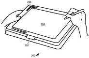
- the portable computer 200is an example of the type of electronic device in which a proximity sensor device for initiating orientation changes in a display can be implemented.
- the portable computer 200is a convertible device, i.e., on that can be operated both as a traditional “notebook” computer and as “tablet” computer.
- a keyboard(not shown in this FIG.) is the primary means of data entry.
- a rotating hinge 202allows the display screen 204 to rotate around and fold down on top of the keyboard, with the display screen 204 visible and covering the keyboard, as shown in FIG. 2 .
- the portable computer 200operates as a tablet computer with the display screen 204 providing the primary means of data entry.
- the display screen 204is also a proximity sensor device that allows a user to interface with the computer using a stylus, fingertip or other object instead of or in addition to the traditional keyboard.
- the portable computer 200can use the display screen 204 and handwriting recognition to provide a user interface to the computer 200 .
- various icons and controls on the display screencan be manipulated and activated using the stylus and/or other object.
- the portable computer 200also includes a proximity sensor device adapted to detect object motion proximate a sensing region 206 and adapted to facilitate orientation changes on the display screen 204 .
- a proximity sensor deviceadapted to detect object motion proximate a sensing region 206 and adapted to facilitate orientation changes on the display screen 204 .
- portable computer 200is again just one example, and that other types of electronic devices can be implemented with the proximity sensor device.
- other types of table computers that do not include dedicated keyboardstypically referred to as “slate” computers, can also be implemented with the proximity sensor device.
- the sensing region 206 of the proximity sensorextends from a plane parallel to the front face of computing device 200 , along with the display 204 . This allows the user to view the display 204 while also viewing the sensing region 206 , even while the orientation of the display 204 is changed with the proximity sensor device.
- a normal vector to the display 204 and a normal vector to the touch surface associated with the sensing region 206would be substantially parallel.
- the touch surfacecan be located on a beveled housing near the display 204 .
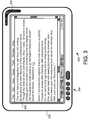
- the electronic devicecomprises a “slate” computer device 300 .
- the slate computer device 300includes a case 302 , a display screen 304 , a plurality of buttons 306 and a proximity sensor device adapted to detect object motion along a sensing region 308 .
- the display screen 304displays the user interface for the computer device 300 .
- the displayed user interfaceincludes a variety of interface elements, including a menu bar, page tabs, scroll bars, a cursor and a clock, as well as a displayed document. It should be noted that this is just one example of a user interface on a display screen, and that many different user interfaces, with different combinations of interface elements and other features can be implemented and their orientation changed with the various embodiments of the invention.
- the proximity sensor deviceprovides a user of computer device 300 with the ability to make orientation changes in the display screen 304 .
- the proximity sensor deviceis implemented to detect object motion along the sensing region 308 and to cause an orientation change in response to the detected motion.
- the proximity sensor deviceis implemented to indicate an orientation change in a first way responsive to detected object motion along the sensing region 308 in a first direction, and is further implemented to indicate an orientation change in a second way responsive to detected object motion along the sensing region 308 in a second direction
- a user of computer device 300can cause orientation changes in different ways through the use of object motions of different directions along the sensing region 308
- the computer device 300is illustrated in a first display orientation, typically referred to as a “landscape” orientation. In this orientation, the natural up and down direction of the display is aligned in the narrow axis, while the natural left and right direction of the display is aligned with the wide axis.
- FIG. 4the computer device 300 is illustrated in a second, different display orientation. This display orientation is typically referred to as a “portrait” orientation. In this orientation, the up and down direction is aligned with wide axis, while the left and right direction is aligned with the narrow axis.
- the most straightforward way to reach the orientation shown in FIG. 4 from the orientation shown in FIG. 3is clockwise rotation of 90 degrees.
- an orientation change in a first waycould comprise a clockwise orientation change or 90 degrees, or the equivalent counter clockwise orientation change of 270 degrees.
- orientation change in a second waycould comprise a counter-clockwise orientation change of 90 degrees, or the equivalent clockwise orientation change of 270 degrees.
- a change in orientation of the displayrefers to the collective change in direction of all major interface elements within the displayed device interface.
- This orientation changeresults in a change in direction for user interface elements while the relative position of the user interface elements within the display is largely unchanged.
- Such a change in orientationdoes not require that every element change their direction. For example, border images, individual circular icons, square switches or other interface elements for which no direction change is desired or needed are not required to change their direction for an effective change in orientation to occur. However, in most cases, the majority, if not all, of the interface elements will change in alignment direction during an orientation change in the display screen.
- the proximity sensor device on computer device 300is implemented to indicate an orientation change in a first way responsive to detected object motion along the sensing region 308 in a first direction, and is further implemented to indicate an orientation change in a second way responsive to detected object motion along the sensing region 308 in a second direction.
- a user of computer device 300can cause orientation changes in different ways through the use of object motions in different directions along the sensing region 308 of the proximity sensor device.
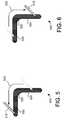
- the proximity sensor device 500defines a sensing region 502 .
- the sensing region 502includes a first portion 504 and a second portion 506 that meet at a corner.
- the first portion 504is arranged along a first axis while the second portion 506 is arranged along a second axis.
- the first and second axesare substantially orthogonal, and the two sensing region portion together provide a sensing region with an overall L-shape.
- the proximity sensor device 500is particularly adaptable to be placed proximate a corner of a typical, rectilinear display screen with the first portion 504 parallel to a first side of the display screen, and the second portion 506 parallel to a second side of the display screen.
- the cornercan be configured to function as part of the first portion 504 , as part of the second portion 506 , as neither the first portion 504 nor the second portion 506 , or as both the first and second portions 504 and 506 in changing display orientation.
- Time multiplexingis one option; for example, the corner can be part of the first portion 504 at certain times (e.g. from when object motion begins in a part of the sensing region 502 that is always the first portion 504 and continuing until the object motion moves away from the sensing region 502 or away from the corner, or vice versa).
- Many other options exist for ascertaining how the corner is treatedranging from the simple to the complex, and include algorithms that use input or positional information history, applications of fuzzy logic, usage of heuristics to decipher user intent, and the like.
- FIG. 5shows the motion of stylus 510 moving along the first portion 504 of the sensing region 502 , turning the corner between the first portion 504 and the second portion 506 , and then moving along the second portion 506 of the sensing region 502 .
- FIG. 5shows one example of how a user can provide object motion along the sensing region 502 in a first direction 520 that is generally counter-clockwise.
- FIG. 6shows the motion of stylus 510 moving along the second portion 506 of the sensing region 502 , turning the corner, and then moving along the first portion 506 of the sensing region 502 .
- FIG. 6shows one example of how a user can provide object motion along the sensing region 502 in a second direction 522 that is generally clockwise.
- the sensor device 500can be implemented to indicate an orientation change in a first way responsive to detected object motion along the sensing region 502 in the first direction 520 , and is further implemented to indicate an orientation change in a second way responsive to detected object motion along the sensing region 502 in the second direction 522 .
- the orientation change in a first waycan comprise a counter-clockwise orientation change of 90 degrees.
- orientation change in the second waycan comprise a clockwise orientation change of 90 degrees.
- the orientation change in a first waycan comprise a counter-clockwise orientation change of 90 degrees
- the orientation change in the second waycan comprise a counter-clockwise orientation change of 270 degrees.
- the user of the electronic devicecan cause effective orientation changes in either of two different directions (clockwise and counter-clockwise) through the use of a single movement along the sensing region 502 simply by moving the object along the sensing region 502 in the desired direction.
- one input devicecan be used to facilitate orientation changes in different direction with two relatively simple and easy to perform gestures.
- some sensor devicescan be implemented to support orientation change in only one direct.
- the sensor devicemay be implemented to generate the same orientation change in response to reverse direction object motion.
- the sensor devicemay be implemented to generate no orientation change and instead generate no response or a different function in response to reverse direction object motion.
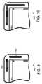
- the proximity sensor deviceis adapted to facilitate orientation changes in different amounts based on the distance of object motion along the entire sensing region or along a specific portion of the sensing region.
- the distance of object motionmay also be the entire distance traversed, or only the component parallel an axis (e.g. along a centerline of a section of the sensing region, or along the entire sensing region).
- FIGS. 7 and 8two examples of object motion along a sensing region 702 in a sensor device 700 are illustrated. In this example, the corner is treated as part of the first portion 704 , and object motion along the sensing region 702 is illustrated through the motion of stylus 710 .
- FIGS. 7 and 8show one example of how a user can provide object motion of two different distances along the sensing region 702 .
- the proximity sensor device 700is adapted to indicate an orientation change of a first amount responsive to detected object motion along the sensing region 702 in the first direction for a first distance, and is further adapted to indicate an orientation change of a second amount responsive to detected object motion along the sensing region 702 in the first direction for a second distance.
- motion of D 1 distancecould correspond to an orientation change of 90 degrees
- motion of a D 2 distancecould correspond to an orientation change of 180 degrees.
- the amount of orientation changecould be set to step according to multiple preset distances corresponding to 45 or 90 degree steps of orientation changes.
- the distance measured and used to determine the amount of orientation changecan be the overall object motion measured along the entire sensing region 702 , or the distance along a particular portion of the sensing region 702 .
- distance required for a set orientation changecan be identified using visual cues, tactile/texture cues, or a combination thereof. These cues can be located in or proximate to the sensing region. This can allow a user to easily determine the amount of distance required to cause a particular orientation change, and thus can improve usability.
- the proximity sensor devicemay be implemented to allow a user to pause the orientation change by stopping the object motion, and then continue the orientation change by resuming object motion along the sensing region 702 .
- the orientation changecan be implemented to continue at an increasing rate, continue at a decreasing rate, or with other variations.
- the orientation changewould not resume without repositioning the object and restarting the gesture.
- orientation changescould be implemented to continue, even after object motion ceases as long as object presence in the sensing region remains.
- the velocity, speed in a particular direction, or absolute speed of the object motioncan be used to determine the rate or amount of orientation change.
- object motion having a speed above a specified valuecan result in 180 degree orientation change, while object motion having a speed below that value can result in a 90 degree orientation change.
- a usercould easily reverse or undo an orientation change by immediately reversing the direction of object motion and continuing for a required distance (e.g. at least a minimum distance) in a different direction (e.g. in the opposite direction). This allows a user to correct for unwanted orientation changes, and for orientation changes of a greater amount than desired.
- the proximity sensor devicefacilitates user control over the orientation of a displayed interface in the display screen with one user input device that responds to relatively simple gestures.
- FIGS. 3-8are all comprised of proximity sensor devices with substantially L-shaped sensing regions demarked to user(s), it should be noted that a variety of different configurations and variations are possible.
- FIG. 9shows a portion of an electronic device 900 that includes a proximity sensor demarked with two distinct sensing region portions 902 and 904 ; sensing region portions 902 and 904 may actually be physically separate regions or merely demarked as such by a housing or some type of overlay.
- Such an embodimentmay b desirable for applications that use the orientation change sensor in functions, such as vertical and horizontal scrolling, where the visual impact of the separate regions helps users comprehend and control the functions more intuitively.
- Such an embodimentmay also be desirable in cases where uniform sensor layout is desirable, or where manufacturing or assembly constraints are such that linear sensing regions are more easily accommodated than ones involving linear and nonlinear regions; this latter case is more likely where the sensing region portions 902 and 904 are actually separate sensing regions.
- FIG. 10shows a portion of an electronic device 1000 that includes a proximity sensor made up of two relatively longer and equivalently-sized sensing region portion.
- a proximity sensormade up of two relatively longer and equivalently-sized sensing region portion.
- a wide variety of lengths, sizes, and shapes of the sensing region portionscan be supported, and can be chosen and configured as appropriate to fit anticipated operating conditions, likely amounts of orientation change, other supported functions, and the like. It should be noted that in other embodiments one or more portions of the sensing region could extend across one or more entire sides. In addition, other embodiments of the sensing region could even include more than two sensing region portions.
- the sensing region portionscan form an “L” matched with a “reversed-L” when they are not connected, or a “C” or a “U” when they are.
- the sensing region portionscan have rounded corners or angular ones, relatively constant width or varying width, linear sections or nonlinear sections, be convex or concave, have any number of edges, and the like.
- the number, widths, lengths, shapes, and configurations of the sensing region portionare quite flexible, and can be defined as appropriate to meet operating requirement.
- the sensing regioncan comprise curved segments, and in some embodiments can include only curved segments with no straight segments.
- the sensing regionscan be implemented in the shape of a partial annulus.
- FIG. 11shows a portion of an electronic device 1100 that includes a proximity sensor made up of three distinct sensing region portions 1102 , 1104 and 1106 .
- the middle portion 1104may provide additional functionality, such as key/button functionality, including non-alphanumeric input such as escape, page up or page down, and the like.
- FIG. 12shows a portion of an electronic device 1200 that includes a proximity sensor that includes regions dedicated to other functions.
- the proximity sensorincludes a corner portion 1202 and two end portions 1204 and 1206 .
- the corner portion 1202could be implemented to function as the L-shaped sensing regions illustrated in FIGS. 3-8 , and can thus facilitate orientation changes in either direction in response to object motion along the corner portion 1206 of the sensing region.
- the end portions 1204 and 1206can then be implemented to provide additional functionality.
- portions 1204 and 1206can be implemented to provide tap zones, cursor motion, scrolling, panning, dragging or some other type of interface navigation on the device 1200 .
- the proximity sensor devicewould be able to provide a variety of different functions in addition to facilitating orientation changes for the display.
- the center portion 1206 and end portions 1204 and 1206are indentified using visual cues, tactile/texture cues, or a combination thereof. This can allow a user to easily recognize the various portions of the sensing region and thus can improve usability.
- the proximity sensor deviceshave defined a sensing region that what proximate the corner and adjacent the edge(s) of the display screen.
- the proximity sensor devicecan be implemented such that the sensing region overlaps one or more edge portions of the display screen.
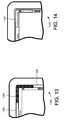
- FIG. 13a portion of electronic device 1300 is illustrated that includes a proximity sensor with a sensing region 1302 that overlaps an edge portion of the display screen 1306 .
- the proximity sensorwould be implemented with a technology that is compatible with the overlapping display screen.
- the proximity sensorcan implemented with a sensor technology that allows images(s) on the display screen to be viewed through the sensing region.
- proximity sensing technologythat disposes transparent or semi-transparent portions overlapping the display screen.
- capacitive technologyis described at U.S. Pat. No. 7,030,860, issued Apr. 18, 2006, and assigned to Synaptics Incorporated.
- Other examplesinclude touch sensors using resistive sensing technology or other capacitive implementations.
- the boundaries of the sensing region 1302can be indicated by any number and combination of passive or active images generated by the underlying display, and thus provide good user indication of how an orientation change can be easily performed.
- the boundaries of the sensing region 1302can also be demarked by physical indication above or bordering the display screen, such as via passive visual indications or active illumination components such as LEDs.
- the sensing region 1302can also be made dynamic and moved to different portions of the display screen as appropriate for the current orientation of the display screen as well as any other images displayed on the display screen.
- the sensing region 1302can even be moved to a central portion of the display screen, and away from any edges of the display screen.
- the sensing region 1402can overlap the displayed image on the display screen without the addition of a border 1304 as shown in FIG. 13 .
- the sensing region and functioncan be accommodated without needing to reduce the size of the displayed image, increasing the size of the display screen, or both.
- the sensing region 1402can be located along the perimeter of the displayed image, overlapping with menu bar(s), window border(s), or whatever is shown underneath the overlapping with menu bar(s), window border(s), or whatever is shown underneath the overlapping sensing region.
- the sensing regionis identified to a user by a partially-transparent image on the display screen, allowing the underlying interface elements to remain visible to the user.
- Other displayed imagesvarying from completely opaque to completely transparent, can also be used.
- the imagescan include any combinations of outlines along the border of the sensing region, visual cues inside the sensing region, or visual cues outside of the sensing region.
- Indications distinct from the displaycan also be used, including markings on the device outside of the display screen (e.g. graphics on a housing). There may also be no indication at all, and users can just understand that particular areas are for display orientation adjustment.
- the sensing region and the corresponding image(s) or indication(s) (if any)can be located elsewhere on the display screen, and along only a portion of the perimeter, along multiple portions of the perimeter, or along the entire perimeter. Further, the sensing regions can overlap only the display screen, only overlap the electronic device outside of the display screen, or overlap both the display screen and portions of the electronic device outside of the display screen.
- proximity sensor devicesimplemented with sensor regions near or overlapping the display screen
- the sensing regioncan be implemented in a corner away from the display screen, on the backside opposite the display screen, or in any other location.
- Several different techniquescan be used to improve the usability of proximity sensor devices to indicate orientation changes in accordance with embodiments of the invention. For example, in some implementations it will be desirable to not cause orientation changes in response to signals representing very small or sudden amounts of sensed object motion. Small amounts of sensed object motion vary from embodiment to embodiment, they are relatively small compared to the expected amounts of object motion given the sensing region design, the sensing technology, noise in the operating environment, and the like.
- Sudden amounts of sensed object motionalso vary from embodiment to embodiment, they occur in shorter spans of time than expected given the sensing region design, the sensing technology, noise in the operating environment, and the like.
- One or more thresholdscan be used to quality input as “small” and “sudden,” and any number or them can be defined at the time of design, manufacture, or dynamically during operation. Defining at design may be desirable if sensor signals are predictable and will vary very little. Defining at manufacture may be desirable if sensor signal difference are high due to part-to-part variation, and are low as users and operating conditions change. Defining dynamically during user may be desirable if the sensor signals are anticipated to very significantly over users, conditions, and time. Criteria can also be combined or enhanced.
- time criteriacan be imposed along with the amount of object motion criteria such that the amount of object motion gauged as “small” or “not small” is the amount of object motion over a defined period of time.
- a speed of the object motioncan be coupled with a time criterion to aid in categorizing “sudden” or “not sudden” object motion.
- Small amounts of sensed object motioncan inadvertently result from attempts by the user to pause and stop moving in the sensing region. In these cases, small amounts of motion caused by bodily tremors or shaking in the environment could be interpreted as intended object motion. Small amounts of sensed object motion can also result from attempts by the user to provide some other type of input if the sensing region is configured to support other types of input. In these cases the small amounts of motion should be processed to cause events other than orientation change. In addition, a user may reduce or stop paying attention to object motion, and accidentally cause drift of the object motion. Further, there may also be cases of accidental input from the user accidentally brushing against the sensing region (these are likely to result in sudden amounts of sensed object motion, large or small).
- Thresholdsmay be maximum or minimum bounds, such that object motion may be “beyond” a maximum threshold when it is above the threshold level and “beyond” a minimum threshold when it is below the threshold level.
- object motion at a thresholdcan also be categorized as meeting the criterion of being “beyond” the threshold. For example, by comparing the sensed object motion to a threshold, the system can ignore sensed levels of object motion that are below the threshold and not cause orientation changes in response to those object motions.
- the thresholdcan be set to filter out object motion less than what is likely to be indicative of intended orientation change, and the proximity sensor device will not consider amounts of sensed object motion below that threshold to be indicative of an orientation change.
- the systemcan ignore sensed levels of object motion that are above a threshold and not generate an orientation change.
- the thresholdcan be set to filter out object combination motion greater than what is likely to be indicative of intended input, and the proximity sensor device will not consider amounts of sense object motion above the threshold to be indicative of object motion.
- a variety of thresholdscan be used, separately or in combination.
- the systemcan require that the object motion travel a minimum distance in the sensing region before responding with results in display orientation change, but accept object motion traveling less than that minimum distance threshold as input intended to trigger other functions, or no input at all (ignorable input).
- the distancecan also be the total distance traversed, distance from a certain point or line, or distance parallel to one or more axes.
- object motion below the distance thresholdwould not then generate an orientation change, it could still be used to trigger other input.
- Further constraintscan be imposed, such as to require that a minimum distance or a maximum distance be traveled within a predetermined amount of time.
- the thresholdmay also alternatively be on another characteristic of the object motion, such as requiring that the speed of the object motion be beyond a certain threshold and/or below a particular threshold before generating an indication of a result.
- Thresholdsmay also be combined, such that an object motion must travel a minimum distance, within a certain amount of time, and reach at least a minimum speed, before indications of results will be provided.
- Another combination of thresholdscan require that an object motion must travel no more than a maximum distance, during a certain amount of time, and not pass (exceed in this case) a maximum speed, such that the system will begin or continue indications of results.
- thresholdsvary with a myriad of factors, such as details of the sensing technology, user interface design, and operating conditions.
- the threshold valuesmay also differ with direction/manners of results, which result is selected, and user preferences.
- the threshold valuescan be made adjustable, such as to change the value in response to determined noisiness of the environment, prior history of typical user input speeds and distances, which result is currently selected, which direction/manner of adjustment is current active, which application(s) are active, or the like. In such a system the adjustments can be user selectable, or made automatic to respond to different operating conditions and/or modes.
- the present inventionthus provides a proximity sensor device and method that facilitates orientation changes in displays.
- the proximity sensor device and methodprovide a user with the ability to indicate an orientation change in a display using the sensing region of a proximity sensor device as a user interface.
- a usercan cause orientation changes in different ways through the user of object motions in different direction along the sensing region. This provides increased usability and flexibility, and allows a user to easily cause different ways of orientation change without requiring multiple buttons, steps or gestures by the user.
Landscapes
- Engineering & Computer Science (AREA)
- Theoretical Computer Science (AREA)
- Computer Hardware Design (AREA)
- Human Computer Interaction (AREA)
- Physics & Mathematics (AREA)
- General Engineering & Computer Science (AREA)
- General Physics & Mathematics (AREA)
- User Interface Of Digital Computer (AREA)
Abstract
Description
Claims (20)
Priority Applications (1)
| Application Number | Priority Date | Filing Date | Title |
|---|---|---|---|
| US11/748,881US7884807B2 (en) | 2007-05-15 | 2007-05-15 | Proximity sensor and method for indicating a display orientation change |
Applications Claiming Priority (1)
| Application Number | Priority Date | Filing Date | Title |
|---|---|---|---|
| US11/748,881US7884807B2 (en) | 2007-05-15 | 2007-05-15 | Proximity sensor and method for indicating a display orientation change |
Publications (2)
| Publication Number | Publication Date |
|---|---|
| US20080284738A1 US20080284738A1 (en) | 2008-11-20 |
| US7884807B2true US7884807B2 (en) | 2011-02-08 |
Family
ID=40027016
Family Applications (1)
| Application Number | Title | Priority Date | Filing Date |
|---|---|---|---|
| US11/748,881Expired - Fee RelatedUS7884807B2 (en) | 2007-05-15 | 2007-05-15 | Proximity sensor and method for indicating a display orientation change |
Country Status (1)
| Country | Link |
|---|---|
| US (1) | US7884807B2 (en) |
Cited By (65)
| Publication number | Priority date | Publication date | Assignee | Title |
|---|---|---|---|---|
| US20090172531A1 (en)* | 2007-12-31 | 2009-07-02 | Hsueh-Chun Chen | Method of displaying menu items and related touch screen device |
| US20090244016A1 (en)* | 2008-03-31 | 2009-10-01 | Dell Products, Lp | Information handling system display device and methods thereof |
| US20100090963A1 (en)* | 2008-10-09 | 2010-04-15 | Lenovo (Singapore) Pte. Ltd. | Slate computer with tactile home keys |
| US20100259515A1 (en)* | 2007-12-13 | 2010-10-14 | Kyocera Corporation | Information Processing Device |
| US20110279393A1 (en)* | 2010-05-13 | 2011-11-17 | Samsung Electronics Co., Ltd. | Method and apparatus for controlling a display unit of a portable terminal |
| US8194926B1 (en)* | 2011-10-05 | 2012-06-05 | Google Inc. | Motion estimation for mobile device user interaction |
| US20120245886A1 (en)* | 2011-03-21 | 2012-09-27 | Hon Hai Precision Industry Co., Ltd. | Electronic device having proximity sensor and method for controlling the same |
| US20130120257A1 (en)* | 2010-08-31 | 2013-05-16 | Eumplus Co., Ltd | Movement sensing device using proximity sensor and method of sensing movement |
| US8498100B1 (en) | 2012-03-02 | 2013-07-30 | Microsoft Corporation | Flexible hinge and removable attachment |
| US8654030B1 (en) | 2012-10-16 | 2014-02-18 | Microsoft Corporation | Antenna placement |
| US8717327B2 (en)* | 2011-07-08 | 2014-05-06 | Nokia Corporation | Controlling responsiveness to user inputs on a touch-sensitive display |
| US8719603B2 (en) | 2012-03-02 | 2014-05-06 | Microsoft Corporation | Accessory device authentication |
| US8733423B1 (en) | 2012-10-17 | 2014-05-27 | Microsoft Corporation | Metal alloy injection molding protrusions |
| US8749529B2 (en) | 2012-03-01 | 2014-06-10 | Microsoft Corporation | Sensor-in-pixel display system with near infrared filter |
| US8786767B2 (en) | 2012-11-02 | 2014-07-22 | Microsoft Corporation | Rapid synchronized lighting and shuttering |
| US20140220959A1 (en)* | 2011-09-09 | 2014-08-07 | Beijing Lenovo Software Ltd. | Electronic terminals and control methods thereof |
| US8873227B2 (en) | 2012-03-02 | 2014-10-28 | Microsoft Corporation | Flexible hinge support layer |
| US8949477B2 (en) | 2012-05-14 | 2015-02-03 | Microsoft Technology Licensing, Llc | Accessory device architecture |
| US8947353B2 (en) | 2012-06-12 | 2015-02-03 | Microsoft Corporation | Photosensor array gesture detection |
| US8952892B2 (en) | 2012-11-01 | 2015-02-10 | Microsoft Corporation | Input location correction tables for input panels |
| US8964379B2 (en) | 2012-08-20 | 2015-02-24 | Microsoft Corporation | Switchable magnetic lock |
| US9019615B2 (en) | 2012-06-12 | 2015-04-28 | Microsoft Technology Licensing, Llc | Wide field-of-view virtual image projector |
| US9027631B2 (en) | 2012-10-17 | 2015-05-12 | Microsoft Technology Licensing, Llc | Metal alloy injection molding overflows |
| US9052414B2 (en) | 2012-02-07 | 2015-06-09 | Microsoft Technology Licensing, Llc | Virtual image device |
| US9064654B2 (en) | 2012-03-02 | 2015-06-23 | Microsoft Technology Licensing, Llc | Method of manufacturing an input device |
| US9075566B2 (en) | 2012-03-02 | 2015-07-07 | Microsoft Technoogy Licensing, LLC | Flexible hinge spine |
| US9073123B2 (en) | 2012-06-13 | 2015-07-07 | Microsoft Technology Licensing, Llc | Housing vents |
| US9152173B2 (en) | 2012-10-09 | 2015-10-06 | Microsoft Technology Licensing, Llc | Transparent display device |
| US9176538B2 (en) | 2013-02-05 | 2015-11-03 | Microsoft Technology Licensing, Llc | Input device configurations |
| US9201185B2 (en) | 2011-02-04 | 2015-12-01 | Microsoft Technology Licensing, Llc | Directional backlighting for display panels |
| US9256089B2 (en) | 2012-06-15 | 2016-02-09 | Microsoft Technology Licensing, Llc | Object-detecting backlight unit |
| US9304549B2 (en) | 2013-03-28 | 2016-04-05 | Microsoft Technology Licensing, Llc | Hinge mechanism for rotatable component attachment |
| US9317072B2 (en) | 2014-01-28 | 2016-04-19 | Microsoft Technology Licensing, Llc | Hinge mechanism with preset positions |
| WO2016061626A1 (en)* | 2014-10-21 | 2016-04-28 | Eat Displays Pty Limited | A display device and content display system |
| US9355345B2 (en) | 2012-07-23 | 2016-05-31 | Microsoft Technology Licensing, Llc | Transparent tags with encoded data |
| US9354748B2 (en) | 2012-02-13 | 2016-05-31 | Microsoft Technology Licensing, Llc | Optical stylus interaction |
| US9360893B2 (en) | 2012-03-02 | 2016-06-07 | Microsoft Technology Licensing, Llc | Input device writing surface |
| US9426905B2 (en) | 2012-03-02 | 2016-08-23 | Microsoft Technology Licensing, Llc | Connection device for computing devices |
| US9448631B2 (en) | 2013-12-31 | 2016-09-20 | Microsoft Technology Licensing, Llc | Input device haptics and pressure sensing |
| US9447620B2 (en) | 2014-09-30 | 2016-09-20 | Microsoft Technology Licensing, Llc | Hinge mechanism with multiple preset positions |
| US9459160B2 (en) | 2012-06-13 | 2016-10-04 | Microsoft Technology Licensing, Llc | Input device sensor configuration |
| US9513748B2 (en) | 2012-12-13 | 2016-12-06 | Microsoft Technology Licensing, Llc | Combined display panel circuit |
| US9552777B2 (en) | 2013-05-10 | 2017-01-24 | Microsoft Technology Licensing, Llc | Phase control backlight |
| US9638835B2 (en) | 2013-03-05 | 2017-05-02 | Microsoft Technology Licensing, Llc | Asymmetric aberration correcting lens |
| US9661770B2 (en) | 2012-10-17 | 2017-05-23 | Microsoft Technology Licensing, Llc | Graphic formation via material ablation |
| US9684382B2 (en) | 2012-06-13 | 2017-06-20 | Microsoft Technology Licensing, Llc | Input device configuration having capacitive and pressure sensors |
| US9752361B2 (en) | 2015-06-18 | 2017-09-05 | Microsoft Technology Licensing, Llc | Multistage hinge |
| US9759854B2 (en) | 2014-02-17 | 2017-09-12 | Microsoft Technology Licensing, Llc | Input device outer layer and backlighting |
| US9864415B2 (en) | 2015-06-30 | 2018-01-09 | Microsoft Technology Licensing, Llc | Multistage friction hinge |
| US9870066B2 (en) | 2012-03-02 | 2018-01-16 | Microsoft Technology Licensing, Llc | Method of manufacturing an input device |
| US10031556B2 (en) | 2012-06-08 | 2018-07-24 | Microsoft Technology Licensing, Llc | User experience adaptation |
| US10037057B2 (en) | 2016-09-22 | 2018-07-31 | Microsoft Technology Licensing, Llc | Friction hinge |
| US10061385B2 (en) | 2016-01-22 | 2018-08-28 | Microsoft Technology Licensing, Llc | Haptic feedback for a touch input device |
| US10120420B2 (en) | 2014-03-21 | 2018-11-06 | Microsoft Technology Licensing, Llc | Lockable display and techniques enabling use of lockable displays |
| US10156889B2 (en) | 2014-09-15 | 2018-12-18 | Microsoft Technology Licensing, Llc | Inductive peripheral retention device |
| US10222889B2 (en) | 2015-06-03 | 2019-03-05 | Microsoft Technology Licensing, Llc | Force inputs and cursor control |
| US10324733B2 (en) | 2014-07-30 | 2019-06-18 | Microsoft Technology Licensing, Llc | Shutdown notifications |
| US10344797B2 (en) | 2016-04-05 | 2019-07-09 | Microsoft Technology Licensing, Llc | Hinge with multiple preset positions |
| US10416799B2 (en) | 2015-06-03 | 2019-09-17 | Microsoft Technology Licensing, Llc | Force sensing and inadvertent input control of an input device |
| US10535323B2 (en) | 2012-02-03 | 2020-01-14 | Dish Technologies Llc | Display zoom controlled by proximity detection |
| CN110730268A (en)* | 2018-07-17 | 2020-01-24 | 华为技术有限公司 | Method and terminal for preventing false touch of ejected proximity light |
| US10558304B2 (en)* | 2016-04-18 | 2020-02-11 | Fujitsu Client Computing Limited | Touch sensor and terminal device |
| US10578499B2 (en) | 2013-02-17 | 2020-03-03 | Microsoft Technology Licensing, Llc | Piezo-actuated virtual buttons for touch surfaces |
| US11163331B2 (en) | 2018-04-27 | 2021-11-02 | Hewlett-Packard Development Company, L.P. | Keyboard mode |
| USRE48963E1 (en) | 2012-03-02 | 2022-03-08 | Microsoft Technology Licensing, Llc | Connection device for computing devices |
Families Citing this family (53)
| Publication number | Priority date | Publication date | Assignee | Title |
|---|---|---|---|---|
| US9213365B2 (en)* | 2010-10-01 | 2015-12-15 | Z124 | Method and system for viewing stacked screen displays using gestures |
| US20120081315A1 (en) | 2010-10-01 | 2012-04-05 | Imerj LLC | Keyboard spanning multiple screens |
| JP2009049512A (en)* | 2007-08-14 | 2009-03-05 | Toshiba Corp | Screen display processing apparatus and method |
| US8219936B2 (en)* | 2007-08-30 | 2012-07-10 | Lg Electronics Inc. | User interface for a mobile device using a user's gesture in the proximity of an electronic device |
| US8432365B2 (en)* | 2007-08-30 | 2013-04-30 | Lg Electronics Inc. | Apparatus and method for providing feedback for three-dimensional touchscreen |
| US8698756B2 (en)* | 2007-11-06 | 2014-04-15 | Stmicroelectronics Asia Pacific Pte Ltd. | Interrupt reduction method in touch screen controller |
| US9513765B2 (en)* | 2007-12-07 | 2016-12-06 | Sony Corporation | Three-dimensional sliding object arrangement method and system |
| KR101012300B1 (en)* | 2008-03-07 | 2011-02-08 | 삼성전자주식회사 | User interface device of portable terminal with touch screen and method thereof |
| US8624844B2 (en) | 2008-04-01 | 2014-01-07 | Litl Llc | Portable computer with multiple display configurations |
| US8577957B2 (en) | 2008-04-01 | 2013-11-05 | Litl Llc | System and method for streamlining user interaction with electronic content |
| US9003315B2 (en) | 2008-04-01 | 2015-04-07 | Litl Llc | System and method for streamlining user interaction with electronic content |
| US8612888B2 (en) | 2008-04-01 | 2013-12-17 | Litl, Llc | Method and apparatus for managing digital media content |
| CN101598972A (en)* | 2008-06-04 | 2009-12-09 | 鸿富锦精密工业(深圳)有限公司 | Electronic device and function changing method thereof |
| US20100088532A1 (en)* | 2008-10-07 | 2010-04-08 | Research In Motion Limited | Method and handheld electronic device having a graphic user interface with efficient orientation sensor use |
| US20100088325A1 (en) | 2008-10-07 | 2010-04-08 | Microsoft Corporation | Streaming Queries |
| US8275412B2 (en)* | 2008-12-31 | 2012-09-25 | Motorola Mobility Llc | Portable electronic device having directional proximity sensors based on device orientation |
| CA2751104C (en)* | 2009-01-29 | 2017-07-04 | Koninklijke Philips Electronics N.V. | Lighting control system responsive to ambient lighting conditions |
| US8355031B2 (en)* | 2009-03-17 | 2013-01-15 | Harris Corporation | Portable electronic devices with adjustable display orientation |
| KR101359755B1 (en) | 2009-03-26 | 2014-02-06 | 노키아 코포레이션 | Apparatus including a sensor arrangement and methods of operating the same |
| US8269175B2 (en)* | 2009-05-22 | 2012-09-18 | Motorola Mobility Llc | Electronic device with sensing assembly and method for detecting gestures of geometric shapes |
| US8542186B2 (en) | 2009-05-22 | 2013-09-24 | Motorola Mobility Llc | Mobile device with user interaction capability and method of operating same |
| US8391719B2 (en) | 2009-05-22 | 2013-03-05 | Motorola Mobility Llc | Method and system for conducting communication between mobile devices |
| US8788676B2 (en)* | 2009-05-22 | 2014-07-22 | Motorola Mobility Llc | Method and system for controlling data transmission to or from a mobile device |
| US8619029B2 (en)* | 2009-05-22 | 2013-12-31 | Motorola Mobility Llc | Electronic device with sensing assembly and method for interpreting consecutive gestures |
| US8304733B2 (en) | 2009-05-22 | 2012-11-06 | Motorola Mobility Llc | Sensing assembly for mobile device |
| KR20100125927A (en)* | 2009-05-22 | 2010-12-01 | 삼성전자주식회사 | Screen switching device and method of a portable terminal |
| US20100327774A1 (en)* | 2009-06-30 | 2010-12-30 | Duncan Robert Kerr | Housing Illumination for Portable Electronic Devices |
| US8319170B2 (en) | 2009-07-10 | 2012-11-27 | Motorola Mobility Llc | Method for adapting a pulse power mode of a proximity sensor |
| US9158816B2 (en) | 2009-10-21 | 2015-10-13 | Microsoft Technology Licensing, Llc | Event processing with XML query based on reusable XML query template |
| KR20110047600A (en)* | 2009-10-30 | 2011-05-09 | 삼성전자주식회사 | Proximity sensing electronics |
| US8665227B2 (en) | 2009-11-19 | 2014-03-04 | Motorola Mobility Llc | Method and apparatus for replicating physical key function with soft keys in an electronic device |
| US9019201B2 (en)* | 2010-01-08 | 2015-04-28 | Microsoft Technology Licensing, Llc | Evolving universal gesture sets |
| KR101694771B1 (en)* | 2010-03-31 | 2017-01-11 | 삼성전자주식회사 | Apparatus and method for determinating user input pattern in portable terminal |
| US9436219B2 (en) | 2010-05-12 | 2016-09-06 | Litl Llc | Remote control to operate computer system |
| US8938753B2 (en) | 2010-05-12 | 2015-01-20 | Litl Llc | Configurable computer system |
| TW201211962A (en)* | 2010-09-15 | 2012-03-16 | Uc Logic Technology Corp | Electromagnetic-type touch display device and method |
| KR20120069442A (en)* | 2010-12-20 | 2012-06-28 | 삼성전자주식회사 | Device and method for controlling data in wireless terminal |
| KR20120084860A (en)* | 2011-01-21 | 2012-07-31 | 삼성전자주식회사 | Method for inputting in capacity touch screen terminal and device thereof |
| US9152255B2 (en) | 2011-05-03 | 2015-10-06 | Htc Corporation | Management and application methods and systems for touch-sensitive devices, and computer program products thereof |
| US10318146B2 (en)* | 2011-09-12 | 2019-06-11 | Microsoft Technology Licensing, Llc | Control area for a touch screen |
| US9182935B2 (en) | 2011-09-27 | 2015-11-10 | Z124 | Secondary single screen mode activation through menu option |
| US10296205B2 (en)* | 2011-12-12 | 2019-05-21 | Sony Corporation | User interface for controlling a display scale of an image |
| US9990119B2 (en)* | 2011-12-15 | 2018-06-05 | Blackberry Limited | Apparatus and method pertaining to display orientation |
| US9964990B2 (en) | 2012-02-21 | 2018-05-08 | Nokia Technologies Oy | Apparatus and associated methods |
| US9785201B2 (en)* | 2012-03-01 | 2017-10-10 | Microsoft Technology Licensing, Llc | Controlling images at mobile devices using sensors |
| US9035880B2 (en) | 2012-03-01 | 2015-05-19 | Microsoft Corporation | Controlling images at hand-held devices |
| US8972853B2 (en)* | 2012-04-13 | 2015-03-03 | Business Objects Software Limited | Rendering digital report elements using a layout optimization tool |
| CN103984423B (en)* | 2013-02-08 | 2016-12-28 | 光宝电子(广州)有限公司 | Contact control mouse and its input method |
| TWI494749B (en)* | 2013-03-15 | 2015-08-01 | Pixart Imaging Inc | Displacement detecting device and power saving method thereof |
| US9772764B2 (en) | 2013-06-06 | 2017-09-26 | Microsoft Technology Licensing, Llc | Accommodating sensors and touch in a unified experience |
| US9122451B2 (en)* | 2013-09-30 | 2015-09-01 | Sonos, Inc. | Capacitive proximity sensor configuration including a speaker grille |
| US9223353B2 (en) | 2013-09-30 | 2015-12-29 | Sonos, Inc. | Ambient light proximity sensing configuration |
| US10932103B1 (en)* | 2014-03-21 | 2021-02-23 | Amazon Technologies, Inc. | Determining position of a user relative to a tote |
Citations (12)
| Publication number | Priority date | Publication date | Assignee | Title |
|---|---|---|---|---|
| US4566001A (en) | 1983-02-08 | 1986-01-21 | Northern Telecom Limited | Touch strip input for display terminal |
| US5335557A (en) | 1991-11-26 | 1994-08-09 | Taizo Yasutake | Touch sensitive input control device |
| US5598527A (en) | 1992-11-12 | 1997-01-28 | Sextant Avionique | Compact and ergonomic communications terminal equipped with proximity detection surfaces |
| US5859629A (en) | 1996-07-01 | 1999-01-12 | Sun Microsystems, Inc. | Linear touch input device |
| US5942733A (en) | 1992-06-08 | 1999-08-24 | Synaptics, Inc. | Stylus input capacitive touchpad sensor |
| US6043809A (en) | 1997-09-23 | 2000-03-28 | Compaq Computer Corporation | Computer keyboard scroll bar control |
| US6639584B1 (en) | 1999-07-06 | 2003-10-28 | Chuang Li | Methods and apparatus for controlling a portable electronic device using a touchpad |
| US6707449B2 (en) | 2000-08-30 | 2004-03-16 | Microsoft Corporation | Manual controlled scrolling |
| US20060026536A1 (en) | 2004-07-30 | 2006-02-02 | Apple Computer, Inc. | Gestures for touch sensitive input devices |
| US7002557B2 (en) | 2002-01-30 | 2006-02-21 | Casio Computer Co., Ltd. | Portable electronic apparatus and a display control method |
| US7088343B2 (en) | 2001-04-30 | 2006-08-08 | Lenovo (Singapore) Pte., Ltd. | Edge touchpad input device |
| US20060238517A1 (en) | 2005-03-04 | 2006-10-26 | Apple Computer, Inc. | Electronic Device Having Display and Surrounding Touch Sensitive Bezel for User Interface and Control |
- 2007
- 2007-05-15USUS11/748,881patent/US7884807B2/ennot_activeExpired - Fee Related
Patent Citations (12)
| Publication number | Priority date | Publication date | Assignee | Title |
|---|---|---|---|---|
| US4566001A (en) | 1983-02-08 | 1986-01-21 | Northern Telecom Limited | Touch strip input for display terminal |
| US5335557A (en) | 1991-11-26 | 1994-08-09 | Taizo Yasutake | Touch sensitive input control device |
| US5942733A (en) | 1992-06-08 | 1999-08-24 | Synaptics, Inc. | Stylus input capacitive touchpad sensor |
| US5598527A (en) | 1992-11-12 | 1997-01-28 | Sextant Avionique | Compact and ergonomic communications terminal equipped with proximity detection surfaces |
| US5859629A (en) | 1996-07-01 | 1999-01-12 | Sun Microsystems, Inc. | Linear touch input device |
| US6043809A (en) | 1997-09-23 | 2000-03-28 | Compaq Computer Corporation | Computer keyboard scroll bar control |
| US6639584B1 (en) | 1999-07-06 | 2003-10-28 | Chuang Li | Methods and apparatus for controlling a portable electronic device using a touchpad |
| US6707449B2 (en) | 2000-08-30 | 2004-03-16 | Microsoft Corporation | Manual controlled scrolling |
| US7088343B2 (en) | 2001-04-30 | 2006-08-08 | Lenovo (Singapore) Pte., Ltd. | Edge touchpad input device |
| US7002557B2 (en) | 2002-01-30 | 2006-02-21 | Casio Computer Co., Ltd. | Portable electronic apparatus and a display control method |
| US20060026536A1 (en) | 2004-07-30 | 2006-02-02 | Apple Computer, Inc. | Gestures for touch sensitive input devices |
| US20060238517A1 (en) | 2005-03-04 | 2006-10-26 | Apple Computer, Inc. | Electronic Device Having Display and Surrounding Touch Sensitive Bezel for User Interface and Control |
Cited By (141)
| Publication number | Priority date | Publication date | Assignee | Title |
|---|---|---|---|---|
| US20100259515A1 (en)* | 2007-12-13 | 2010-10-14 | Kyocera Corporation | Information Processing Device |
| US8760441B2 (en)* | 2007-12-13 | 2014-06-24 | Kyocera Corporation | Information processing device |
| US20090172531A1 (en)* | 2007-12-31 | 2009-07-02 | Hsueh-Chun Chen | Method of displaying menu items and related touch screen device |
| US8302004B2 (en)* | 2007-12-31 | 2012-10-30 | Htc Corporation | Method of displaying menu items and related touch screen device |
| US8259080B2 (en)* | 2008-03-31 | 2012-09-04 | Dell Products, Lp | Information handling system display device and methods thereof |
| US20090244016A1 (en)* | 2008-03-31 | 2009-10-01 | Dell Products, Lp | Information handling system display device and methods thereof |
| US20100090963A1 (en)* | 2008-10-09 | 2010-04-15 | Lenovo (Singapore) Pte. Ltd. | Slate computer with tactile home keys |
| US9104311B2 (en)* | 2008-10-09 | 2015-08-11 | Lenovo (Singapore) Pte. Ltd. | Slate computer with tactile home keys |
| US20110279393A1 (en)* | 2010-05-13 | 2011-11-17 | Samsung Electronics Co., Ltd. | Method and apparatus for controlling a display unit of a portable terminal |
| US20130120257A1 (en)* | 2010-08-31 | 2013-05-16 | Eumplus Co., Ltd | Movement sensing device using proximity sensor and method of sensing movement |
| US9201185B2 (en) | 2011-02-04 | 2015-12-01 | Microsoft Technology Licensing, Llc | Directional backlighting for display panels |
| US20120245886A1 (en)* | 2011-03-21 | 2012-09-27 | Hon Hai Precision Industry Co., Ltd. | Electronic device having proximity sensor and method for controlling the same |
| US8855966B2 (en)* | 2011-03-21 | 2014-10-07 | Ambit Microsystems (Shanghai) Ltd. | Electronic device having proximity sensor and method for controlling the same |
| US8717327B2 (en)* | 2011-07-08 | 2014-05-06 | Nokia Corporation | Controlling responsiveness to user inputs on a touch-sensitive display |
| US20140220959A1 (en)* | 2011-09-09 | 2014-08-07 | Beijing Lenovo Software Ltd. | Electronic terminals and control methods thereof |
| US9204304B2 (en)* | 2011-09-09 | 2015-12-01 | Lenovo (Beijing) Limited | Electronic terminals and control methods thereof |
| US8194926B1 (en)* | 2011-10-05 | 2012-06-05 | Google Inc. | Motion estimation for mobile device user interaction |
| US10535323B2 (en) | 2012-02-03 | 2020-01-14 | Dish Technologies Llc | Display zoom controlled by proximity detection |
| US9052414B2 (en) | 2012-02-07 | 2015-06-09 | Microsoft Technology Licensing, Llc | Virtual image device |
| US9354748B2 (en) | 2012-02-13 | 2016-05-31 | Microsoft Technology Licensing, Llc | Optical stylus interaction |
| US8749529B2 (en) | 2012-03-01 | 2014-06-10 | Microsoft Corporation | Sensor-in-pixel display system with near infrared filter |
| US9275809B2 (en) | 2012-03-02 | 2016-03-01 | Microsoft Technology Licensing, Llc | Device camera angle |
| US9360893B2 (en) | 2012-03-02 | 2016-06-07 | Microsoft Technology Licensing, Llc | Input device writing surface |
| US8724302B2 (en) | 2012-03-02 | 2014-05-13 | Microsoft Corporation | Flexible hinge support layer |
| USRE48963E1 (en) | 2012-03-02 | 2022-03-08 | Microsoft Technology Licensing, Llc | Connection device for computing devices |
| US8699215B2 (en) | 2012-03-02 | 2014-04-15 | Microsoft Corporation | Flexible hinge spine |
| US10963087B2 (en) | 2012-03-02 | 2021-03-30 | Microsoft Technology Licensing, Llc | Pressure sensitive keys |
| US8780540B2 (en) | 2012-03-02 | 2014-07-15 | Microsoft Corporation | Flexible hinge and removable attachment |
| US8780541B2 (en) | 2012-03-02 | 2014-07-15 | Microsoft Corporation | Flexible hinge and removable attachment |
| US8498100B1 (en) | 2012-03-02 | 2013-07-30 | Microsoft Corporation | Flexible hinge and removable attachment |
| US8791382B2 (en) | 2012-03-02 | 2014-07-29 | Microsoft Corporation | Input device securing techniques |
| US8646999B2 (en) | 2012-03-02 | 2014-02-11 | Microsoft Corporation | Pressure sensitive key normalization |
| US8830668B2 (en) | 2012-03-02 | 2014-09-09 | Microsoft Corporation | Flexible hinge and removable attachment |
| US8850241B2 (en) | 2012-03-02 | 2014-09-30 | Microsoft Corporation | Multi-stage power adapter configured to provide low power upon initial connection of the power adapter to the host device and high power thereafter upon notification from the host device to the power adapter |
| US20140012401A1 (en)* | 2012-03-02 | 2014-01-09 | Microsoft Corporation | Sensor Fusion Algorithm |
| US8854799B2 (en) | 2012-03-02 | 2014-10-07 | Microsoft Corporation | Flux fountain |
| US8873227B2 (en) | 2012-03-02 | 2014-10-28 | Microsoft Corporation | Flexible hinge support layer |
| US8896993B2 (en) | 2012-03-02 | 2014-11-25 | Microsoft Corporation | Input device layers and nesting |
| US8903517B2 (en)* | 2012-03-02 | 2014-12-02 | Microsoft Corporation | Computer device and an apparatus having sensors configured for measuring spatial information indicative of a position of the computing devices |
| US8935774B2 (en) | 2012-03-02 | 2015-01-13 | Microsoft Corporation | Accessory device authentication |
| US8947864B2 (en) | 2012-03-02 | 2015-02-03 | Microsoft Corporation | Flexible hinge and removable attachment |
| US10013030B2 (en) | 2012-03-02 | 2018-07-03 | Microsoft Technology Licensing, Llc | Multiple position input device cover |
| US9946307B2 (en) | 2012-03-02 | 2018-04-17 | Microsoft Technology Licensing, Llc | Classifying the intent of user input |
| US9904327B2 (en) | 2012-03-02 | 2018-02-27 | Microsoft Technology Licensing, Llc | Flexible hinge and removable attachment |
| US9870066B2 (en) | 2012-03-02 | 2018-01-16 | Microsoft Technology Licensing, Llc | Method of manufacturing an input device |
| US9852855B2 (en) | 2012-03-02 | 2017-12-26 | Microsoft Technology Licensing, Llc | Pressure sensitive key normalization |
| US9793073B2 (en) | 2012-03-02 | 2017-10-17 | Microsoft Technology Licensing, Llc | Backlighting a fabric enclosure of a flexible cover |
| US9766663B2 (en) | 2012-03-02 | 2017-09-19 | Microsoft Technology Licensing, Llc | Hinge for component attachment |
| US9047207B2 (en) | 2012-03-02 | 2015-06-02 | Microsoft Technology Licensing, Llc | Mobile device power state |
| US8614666B2 (en) | 2012-03-02 | 2013-12-24 | Microsoft Corporation | Sensing user input at display area edge |
| US9064654B2 (en) | 2012-03-02 | 2015-06-23 | Microsoft Technology Licensing, Llc | Method of manufacturing an input device |
| US9075566B2 (en) | 2012-03-02 | 2015-07-07 | Microsoft Technoogy Licensing, LLC | Flexible hinge spine |
| US9710093B2 (en) | 2012-03-02 | 2017-07-18 | Microsoft Technology Licensing, Llc | Pressure sensitive key normalization |
| US9678542B2 (en) | 2012-03-02 | 2017-06-13 | Microsoft Technology Licensing, Llc | Multiple position input device cover |
| US9098117B2 (en) | 2012-03-02 | 2015-08-04 | Microsoft Technology Licensing, Llc | Classifying the intent of user input |
| US8610015B2 (en) | 2012-03-02 | 2013-12-17 | Microsoft Corporation | Input device securing techniques |
| US9111703B2 (en) | 2012-03-02 | 2015-08-18 | Microsoft Technology Licensing, Llc | Sensor stack venting |
| US9116550B2 (en) | 2012-03-02 | 2015-08-25 | Microsoft Technology Licensing, Llc | Device kickstand |
| US9134808B2 (en) | 2012-03-02 | 2015-09-15 | Microsoft Technology Licensing, Llc | Device kickstand |
| US9134807B2 (en) | 2012-03-02 | 2015-09-15 | Microsoft Technology Licensing, Llc | Pressure sensitive key normalization |
| US9146620B2 (en) | 2012-03-02 | 2015-09-29 | Microsoft Technology Licensing, Llc | Input device assembly |
| US9619071B2 (en) | 2012-03-02 | 2017-04-11 | Microsoft Technology Licensing, Llc | Computing device and an apparatus having sensors configured for measuring spatial information indicative of a position of the computing devices |
| US9158383B2 (en) | 2012-03-02 | 2015-10-13 | Microsoft Technology Licensing, Llc | Force concentrator |
| US9158384B2 (en) | 2012-03-02 | 2015-10-13 | Microsoft Technology Licensing, Llc | Flexible hinge protrusion attachment |
| US9618977B2 (en) | 2012-03-02 | 2017-04-11 | Microsoft Technology Licensing, Llc | Input device securing techniques |
| US9176900B2 (en) | 2012-03-02 | 2015-11-03 | Microsoft Technology Licensing, Llc | Flexible hinge and removable attachment |
| US9176901B2 (en) | 2012-03-02 | 2015-11-03 | Microsoft Technology Licensing, Llc | Flux fountain |
| US8570725B2 (en) | 2012-03-02 | 2013-10-29 | Microsoft Corporation | Flexible hinge and removable attachment |
| US8564944B2 (en) | 2012-03-02 | 2013-10-22 | Microsoft Corporation | Flux fountain |
| US9465412B2 (en) | 2012-03-02 | 2016-10-11 | Microsoft Technology Licensing, Llc | Input device layers and nesting |
| US9268373B2 (en) | 2012-03-02 | 2016-02-23 | Microsoft Technology Licensing, Llc | Flexible hinge spine |
| US8548608B2 (en)* | 2012-03-02 | 2013-10-01 | Microsoft Corporation | Sensor fusion algorithm |
| US9298236B2 (en) | 2012-03-02 | 2016-03-29 | Microsoft Technology Licensing, Llc | Multi-stage power adapter configured to provide a first power level upon initial connection of the power adapter to the host device and a second power level thereafter upon notification from the host device to the power adapter |
| US9304948B2 (en) | 2012-03-02 | 2016-04-05 | Microsoft Technology Licensing, Llc | Sensing user input at display area edge |
| US9304949B2 (en) | 2012-03-02 | 2016-04-05 | Microsoft Technology Licensing, Llc | Sensing user input at display area edge |
| US9460029B2 (en) | 2012-03-02 | 2016-10-04 | Microsoft Technology Licensing, Llc | Pressure sensitive keys |
| US9426905B2 (en) | 2012-03-02 | 2016-08-23 | Microsoft Technology Licensing, Llc | Connection device for computing devices |
| US9411751B2 (en) | 2012-03-02 | 2016-08-09 | Microsoft Technology Licensing, Llc | Key formation |
| US8719603B2 (en) | 2012-03-02 | 2014-05-06 | Microsoft Corporation | Accessory device authentication |
| US8543227B1 (en)* | 2012-03-02 | 2013-09-24 | Microsoft Corporation | Sensor fusion algorithm |
| US9348605B2 (en) | 2012-05-14 | 2016-05-24 | Microsoft Technology Licensing, Llc | System and method for accessory device architecture that passes human interface device (HID) data via intermediate processor |
| US9098304B2 (en) | 2012-05-14 | 2015-08-04 | Microsoft Technology Licensing, Llc | Device enumeration support method for computing devices that does not natively support device enumeration |
| US9959241B2 (en) | 2012-05-14 | 2018-05-01 | Microsoft Technology Licensing, Llc | System and method for accessory device architecture that passes via intermediate processor a descriptor when processing in a low power state |
| US8949477B2 (en) | 2012-05-14 | 2015-02-03 | Microsoft Technology Licensing, Llc | Accessory device architecture |
| US10031556B2 (en) | 2012-06-08 | 2018-07-24 | Microsoft Technology Licensing, Llc | User experience adaptation |
| US10107994B2 (en) | 2012-06-12 | 2018-10-23 | Microsoft Technology Licensing, Llc | Wide field-of-view virtual image projector |
| US9019615B2 (en) | 2012-06-12 | 2015-04-28 | Microsoft Technology Licensing, Llc | Wide field-of-view virtual image projector |
| US8947353B2 (en) | 2012-06-12 | 2015-02-03 | Microsoft Corporation | Photosensor array gesture detection |
| US9684382B2 (en) | 2012-06-13 | 2017-06-20 | Microsoft Technology Licensing, Llc | Input device configuration having capacitive and pressure sensors |
| US9459160B2 (en) | 2012-06-13 | 2016-10-04 | Microsoft Technology Licensing, Llc | Input device sensor configuration |
| US9952106B2 (en) | 2012-06-13 | 2018-04-24 | Microsoft Technology Licensing, Llc | Input device sensor configuration |
| US10228770B2 (en) | 2012-06-13 | 2019-03-12 | Microsoft Technology Licensing, Llc | Input device configuration having capacitive and pressure sensors |
| US9073123B2 (en) | 2012-06-13 | 2015-07-07 | Microsoft Technology Licensing, Llc | Housing vents |
| US9256089B2 (en) | 2012-06-15 | 2016-02-09 | Microsoft Technology Licensing, Llc | Object-detecting backlight unit |
| US9355345B2 (en) | 2012-07-23 | 2016-05-31 | Microsoft Technology Licensing, Llc | Transparent tags with encoded data |
| US8964379B2 (en) | 2012-08-20 | 2015-02-24 | Microsoft Corporation | Switchable magnetic lock |
| US9824808B2 (en) | 2012-08-20 | 2017-11-21 | Microsoft Technology Licensing, Llc | Switchable magnetic lock |
| US9152173B2 (en) | 2012-10-09 | 2015-10-06 | Microsoft Technology Licensing, Llc | Transparent display device |
| US8654030B1 (en) | 2012-10-16 | 2014-02-18 | Microsoft Corporation | Antenna placement |
| US9432070B2 (en) | 2012-10-16 | 2016-08-30 | Microsoft Technology Licensing, Llc | Antenna placement |
| US9661770B2 (en) | 2012-10-17 | 2017-05-23 | Microsoft Technology Licensing, Llc | Graphic formation via material ablation |
| US9027631B2 (en) | 2012-10-17 | 2015-05-12 | Microsoft Technology Licensing, Llc | Metal alloy injection molding overflows |
| US8733423B1 (en) | 2012-10-17 | 2014-05-27 | Microsoft Corporation | Metal alloy injection molding protrusions |
| US8991473B2 (en) | 2012-10-17 | 2015-03-31 | Microsoft Technology Holding, LLC | Metal alloy injection molding protrusions |
| US8952892B2 (en) | 2012-11-01 | 2015-02-10 | Microsoft Corporation | Input location correction tables for input panels |
| US8786767B2 (en) | 2012-11-02 | 2014-07-22 | Microsoft Corporation | Rapid synchronized lighting and shuttering |
| US9544504B2 (en) | 2012-11-02 | 2017-01-10 | Microsoft Technology Licensing, Llc | Rapid synchronized lighting and shuttering |
| US9513748B2 (en) | 2012-12-13 | 2016-12-06 | Microsoft Technology Licensing, Llc | Combined display panel circuit |
| US9176538B2 (en) | 2013-02-05 | 2015-11-03 | Microsoft Technology Licensing, Llc | Input device configurations |
| US10578499B2 (en) | 2013-02-17 | 2020-03-03 | Microsoft Technology Licensing, Llc | Piezo-actuated virtual buttons for touch surfaces |
| US9638835B2 (en) | 2013-03-05 | 2017-05-02 | Microsoft Technology Licensing, Llc | Asymmetric aberration correcting lens |
| US9304549B2 (en) | 2013-03-28 | 2016-04-05 | Microsoft Technology Licensing, Llc | Hinge mechanism for rotatable component attachment |
| US9552777B2 (en) | 2013-05-10 | 2017-01-24 | Microsoft Technology Licensing, Llc | Phase control backlight |
| US9448631B2 (en) | 2013-12-31 | 2016-09-20 | Microsoft Technology Licensing, Llc | Input device haptics and pressure sensing |
| US10359848B2 (en) | 2013-12-31 | 2019-07-23 | Microsoft Technology Licensing, Llc | Input device haptics and pressure sensing |
| US9317072B2 (en) | 2014-01-28 | 2016-04-19 | Microsoft Technology Licensing, Llc | Hinge mechanism with preset positions |
| US9759854B2 (en) | 2014-02-17 | 2017-09-12 | Microsoft Technology Licensing, Llc | Input device outer layer and backlighting |
| US10120420B2 (en) | 2014-03-21 | 2018-11-06 | Microsoft Technology Licensing, Llc | Lockable display and techniques enabling use of lockable displays |
| US10324733B2 (en) | 2014-07-30 | 2019-06-18 | Microsoft Technology Licensing, Llc | Shutdown notifications |
| US10156889B2 (en) | 2014-09-15 | 2018-12-18 | Microsoft Technology Licensing, Llc | Inductive peripheral retention device |
| US9447620B2 (en) | 2014-09-30 | 2016-09-20 | Microsoft Technology Licensing, Llc | Hinge mechanism with multiple preset positions |
| US9964998B2 (en) | 2014-09-30 | 2018-05-08 | Microsoft Technology Licensing, Llc | Hinge mechanism with multiple preset positions |
| AU2015336940B2 (en)* | 2014-10-21 | 2017-04-27 | Eat Displays Pty Limited | A display device and content display system |
| WO2016061626A1 (en)* | 2014-10-21 | 2016-04-28 | Eat Displays Pty Limited | A display device and content display system |
| AU2017202045A1 (en)* | 2014-10-21 | 2017-05-11 | Eat Displays Pty Limited | A display device and content display system |
| AU2017202044A1 (en)* | 2014-10-21 | 2017-05-11 | Eat Displays Pty Limited | A display device and content display system |
| US10672031B2 (en) | 2014-10-21 | 2020-06-02 | Eat Displays Pty Limited | Display device and content display system |
| AU2017202044B2 (en)* | 2014-10-21 | 2017-08-31 | Eat Displays Pty Limited | A display device and content display system |
| US10222889B2 (en) | 2015-06-03 | 2019-03-05 | Microsoft Technology Licensing, Llc | Force inputs and cursor control |
| US10416799B2 (en) | 2015-06-03 | 2019-09-17 | Microsoft Technology Licensing, Llc | Force sensing and inadvertent input control of an input device |
| US9752361B2 (en) | 2015-06-18 | 2017-09-05 | Microsoft Technology Licensing, Llc | Multistage hinge |
| US10606322B2 (en) | 2015-06-30 | 2020-03-31 | Microsoft Technology Licensing, Llc | Multistage friction hinge |
| US9864415B2 (en) | 2015-06-30 | 2018-01-09 | Microsoft Technology Licensing, Llc | Multistage friction hinge |
| US10061385B2 (en) | 2016-01-22 | 2018-08-28 | Microsoft Technology Licensing, Llc | Haptic feedback for a touch input device |
| US10344797B2 (en) | 2016-04-05 | 2019-07-09 | Microsoft Technology Licensing, Llc | Hinge with multiple preset positions |
| US10558304B2 (en)* | 2016-04-18 | 2020-02-11 | Fujitsu Client Computing Limited | Touch sensor and terminal device |
| US10037057B2 (en) | 2016-09-22 | 2018-07-31 | Microsoft Technology Licensing, Llc | Friction hinge |
| US11163331B2 (en) | 2018-04-27 | 2021-11-02 | Hewlett-Packard Development Company, L.P. | Keyboard mode |
| CN110730268A (en)* | 2018-07-17 | 2020-01-24 | 华为技术有限公司 | Method and terminal for preventing false touch of ejected proximity light |
| CN110730268B (en)* | 2018-07-17 | 2022-05-06 | 荣耀终端有限公司 | Method and terminal for preventing false touch of ejected proximity light |
| US11606455B2 (en) | 2018-07-17 | 2023-03-14 | Honor Device Co., Ltd. | Method for preventing mistouch by using top-emitted proximity light, and terminal |
Also Published As
| Publication number | Publication date |
|---|---|
| US20080284738A1 (en) | 2008-11-20 |
Similar Documents
| Publication | Publication Date | Title |
|---|---|---|
| US7884807B2 (en) | Proximity sensor and method for indicating a display orientation change | |
| US11886699B2 (en) | Selective rejection of touch contacts in an edge region of a touch surface | |
| US7825797B2 (en) | Proximity sensor device and method with adjustment selection tabs | |
| US9703435B2 (en) | Touchpad combined with a display and having proximity and touch sensing capabilities to enable different functions or interfaces to be displayed | |
| US8174504B2 (en) | Input device and method for adjusting a parameter of an electronic system | |
| CN104185831B (en) | Systems and methods for dynamically adjusting user interface parameters using input devices | |
| US20070262951A1 (en) | Proximity sensor device and method with improved indication of adjustment | |
| JP6577967B2 (en) | Method of adjusting moving direction of display object and terminal | |
| US20090289902A1 (en) | Proximity sensor device and method with subregion based swipethrough data entry | |
| US20090288889A1 (en) | Proximity sensor device and method with swipethrough data entry | |
| US20100177053A2 (en) | Method and apparatus for control of multiple degrees of freedom of a display | |
| US20100117961A1 (en) | Detecting a palm touch on a surface | |
| KR20170081281A (en) | Detection of gesture orientation on repositionable touch surface | |
| US20170024553A1 (en) | Temporary secure access via input object remaining in place | |
| AU2015271962B2 (en) | Interpreting touch contacts on a touch surface | |
| KR101251578B1 (en) | Optical input device using side directional light source | |
| HK1133709A (en) | Selective rejection of touch contacts in an edge region of a touch surface | |
| HK1169182A (en) | Selective rejection of touch contacts in an edge region of a touch surface |
Legal Events
| Date | Code | Title | Description |
|---|---|---|---|
| AS | Assignment | Owner name:SYNAPTICS INCORPORATED, CALIFORNIA Free format text:ASSIGNMENT OF ASSIGNORS INTEREST;ASSIGNORS:HOVDEN, TORBJORN;HUIE, MARK ANDREW;LE, THUY THANH BICH;AND OTHERS;REEL/FRAME:019296/0777;SIGNING DATES FROM 20070508 TO 20070514 Owner name:SYNAPTICS INCORPORATED, CALIFORNIA Free format text:ASSIGNMENT OF ASSIGNORS INTEREST;ASSIGNORS:HOVDEN, TORBJORN;HUIE, MARK ANDREW;LE, THUY THANH BICH;AND OTHERS;SIGNING DATES FROM 20070508 TO 20070514;REEL/FRAME:019296/0777 | |
| FPAY | Fee payment | Year of fee payment:4 | |
| AS | Assignment | Owner name:WELLS FARGO BANK, NATIONAL ASSOCIATION, NORTH CARO Free format text:SECURITY INTEREST;ASSIGNOR:SYNAPTICS INCORPORATED;REEL/FRAME:033888/0851 Effective date:20140930 | |
| AS | Assignment | Owner name:WELLS FARGO BANK, NATIONAL ASSOCIATION, NORTH CAROLINA Free format text:SECURITY INTEREST;ASSIGNOR:SYNAPTICS INCORPORATED;REEL/FRAME:044037/0896 Effective date:20170927 Owner name:WELLS FARGO BANK, NATIONAL ASSOCIATION, NORTH CARO Free format text:SECURITY INTEREST;ASSIGNOR:SYNAPTICS INCORPORATED;REEL/FRAME:044037/0896 Effective date:20170927 | |
| FEPP | Fee payment procedure | Free format text:MAINTENANCE FEE REMINDER MAILED (ORIGINAL EVENT CODE: REM.); ENTITY STATUS OF PATENT OWNER: LARGE ENTITY | |
| LAPS | Lapse for failure to pay maintenance fees | Free format text:PATENT EXPIRED FOR FAILURE TO PAY MAINTENANCE FEES (ORIGINAL EVENT CODE: EXP.); ENTITY STATUS OF PATENT OWNER: LARGE ENTITY | |
| STCH | Information on status: patent discontinuation | Free format text:PATENT EXPIRED DUE TO NONPAYMENT OF MAINTENANCE FEES UNDER 37 CFR 1.362 | |
| FP | Lapsed due to failure to pay maintenance fee | Effective date:20190208 | |
| AS | Assignment | Owner name:SYNAPTICS INCORPORATED, CALIFORNIA Free format text:RELEASE BY SECURED PARTY;ASSIGNOR:WELLS FARGO BANK, NATIONAL ASSOCIATION;REEL/FRAME:050206/0252 Effective date:20190805 | |
| AS | Assignment | Owner name:WACOM CO., LTD., JAPAN Free format text:ASSIGNMENT OF ASSIGNORS INTEREST;ASSIGNOR:SYNAPTICS INCORPORATED;REEL/FRAME:050229/0145 Effective date:20190827 |