US7884724B2 - Radio frequency data communications device with selectively removable antenna portion and method - Google Patents
Radio frequency data communications device with selectively removable antenna portion and methodDownload PDFInfo
- Publication number
- US7884724B2 US7884724B2US11/607,251US60725106AUS7884724B2US 7884724 B2US7884724 B2US 7884724B2US 60725106 AUS60725106 AUS 60725106AUS 7884724 B2US7884724 B2US 7884724B2
- Authority
- US
- United States
- Prior art keywords
- radio frequency
- receiver sensitivity
- rfid tag
- antenna
- frequency signals
- Prior art date
- Legal status (The legal status is an assumption and is not a legal conclusion. Google has not performed a legal analysis and makes no representation as to the accuracy of the status listed.)
- Expired - Fee Related, expires
Links
Images


Classifications
- H—ELECTRICITY
- H01—ELECTRIC ELEMENTS
- H01Q—ANTENNAS, i.e. RADIO AERIALS
- H01Q1/00—Details of, or arrangements associated with, antennas
- H01Q1/12—Supports; Mounting means
- H01Q1/22—Supports; Mounting means by structural association with other equipment or articles
- H01Q1/2208—Supports; Mounting means by structural association with other equipment or articles associated with components used in interrogation type services, i.e. in systems for information exchange between an interrogator/reader and a tag/transponder, e.g. in Radio Frequency Identification [RFID] systems
- H01Q1/2225—Supports; Mounting means by structural association with other equipment or articles associated with components used in interrogation type services, i.e. in systems for information exchange between an interrogator/reader and a tag/transponder, e.g. in Radio Frequency Identification [RFID] systems used in active tags, i.e. provided with its own power source or in passive tags, i.e. deriving power from RF signal
- G—PHYSICS
- G01—MEASURING; TESTING
- G01S—RADIO DIRECTION-FINDING; RADIO NAVIGATION; DETERMINING DISTANCE OR VELOCITY BY USE OF RADIO WAVES; LOCATING OR PRESENCE-DETECTING BY USE OF THE REFLECTION OR RERADIATION OF RADIO WAVES; ANALOGOUS ARRANGEMENTS USING OTHER WAVES
- G01S13/00—Systems using the reflection or reradiation of radio waves, e.g. radar systems; Analogous systems using reflection or reradiation of waves whose nature or wavelength is irrelevant or unspecified
- G01S13/74—Systems using reradiation of radio waves, e.g. secondary radar systems; Analogous systems
- G01S13/76—Systems using reradiation of radio waves, e.g. secondary radar systems; Analogous systems wherein pulse-type signals are transmitted
- G01S13/767—Responders; Transponders
- G—PHYSICS
- G01—MEASURING; TESTING
- G01S—RADIO DIRECTION-FINDING; RADIO NAVIGATION; DETERMINING DISTANCE OR VELOCITY BY USE OF RADIO WAVES; LOCATING OR PRESENCE-DETECTING BY USE OF THE REFLECTION OR RERADIATION OF RADIO WAVES; ANALOGOUS ARRANGEMENTS USING OTHER WAVES
- G01S13/00—Systems using the reflection or reradiation of radio waves, e.g. radar systems; Analogous systems using reflection or reradiation of waves whose nature or wavelength is irrelevant or unspecified
- G01S13/74—Systems using reradiation of radio waves, e.g. secondary radar systems; Analogous systems
- G01S13/76—Systems using reradiation of radio waves, e.g. secondary radar systems; Analogous systems wherein pulse-type signals are transmitted
- G01S13/78—Systems using reradiation of radio waves, e.g. secondary radar systems; Analogous systems wherein pulse-type signals are transmitted discriminating between different kinds of targets, e.g. IFF-radar, i.e. identification of friend or foe
- G—PHYSICS
- G06—COMPUTING OR CALCULATING; COUNTING
- G06K—GRAPHICAL DATA READING; PRESENTATION OF DATA; RECORD CARRIERS; HANDLING RECORD CARRIERS
- G06K19/00—Record carriers for use with machines and with at least a part designed to carry digital markings
- G06K19/06—Record carriers for use with machines and with at least a part designed to carry digital markings characterised by the kind of the digital marking, e.g. shape, nature, code
- G06K19/067—Record carriers with conductive marks, printed circuits or semiconductor circuit elements, e.g. credit or identity cards also with resonating or responding marks without active components
- G06K19/07—Record carriers with conductive marks, printed circuits or semiconductor circuit elements, e.g. credit or identity cards also with resonating or responding marks without active components with integrated circuit chips
- G06K19/0723—Record carriers with conductive marks, printed circuits or semiconductor circuit elements, e.g. credit or identity cards also with resonating or responding marks without active components with integrated circuit chips the record carrier comprising an arrangement for non-contact communication, e.g. wireless communication circuits on transponder cards, non-contact smart cards or RFIDs
- G06K19/0726—Record carriers with conductive marks, printed circuits or semiconductor circuit elements, e.g. credit or identity cards also with resonating or responding marks without active components with integrated circuit chips the record carrier comprising an arrangement for non-contact communication, e.g. wireless communication circuits on transponder cards, non-contact smart cards or RFIDs the arrangement including a circuit for tuning the resonance frequency of an antenna on the record carrier
- G—PHYSICS
- G06—COMPUTING OR CALCULATING; COUNTING
- G06K—GRAPHICAL DATA READING; PRESENTATION OF DATA; RECORD CARRIERS; HANDLING RECORD CARRIERS
- G06K19/00—Record carriers for use with machines and with at least a part designed to carry digital markings
- G06K19/06—Record carriers for use with machines and with at least a part designed to carry digital markings characterised by the kind of the digital marking, e.g. shape, nature, code
- G06K19/067—Record carriers with conductive marks, printed circuits or semiconductor circuit elements, e.g. credit or identity cards also with resonating or responding marks without active components
- G06K19/07—Record carriers with conductive marks, printed circuits or semiconductor circuit elements, e.g. credit or identity cards also with resonating or responding marks without active components with integrated circuit chips
- G06K19/077—Constructional details, e.g. mounting of circuits in the carrier
- G06K19/07749—Constructional details, e.g. mounting of circuits in the carrier the record carrier being capable of non-contact communication, e.g. constructional details of the antenna of a non-contact smart card
- G—PHYSICS
- G06—COMPUTING OR CALCULATING; COUNTING
- G06K—GRAPHICAL DATA READING; PRESENTATION OF DATA; RECORD CARRIERS; HANDLING RECORD CARRIERS
- G06K7/00—Methods or arrangements for sensing record carriers, e.g. for reading patterns
- G06K7/10—Methods or arrangements for sensing record carriers, e.g. for reading patterns by electromagnetic radiation, e.g. optical sensing; by corpuscular radiation
- G06K7/10009—Methods or arrangements for sensing record carriers, e.g. for reading patterns by electromagnetic radiation, e.g. optical sensing; by corpuscular radiation sensing by radiation using wavelengths larger than 0.1 mm, e.g. radio-waves or microwaves
- G06K7/10316—Methods or arrangements for sensing record carriers, e.g. for reading patterns by electromagnetic radiation, e.g. optical sensing; by corpuscular radiation sensing by radiation using wavelengths larger than 0.1 mm, e.g. radio-waves or microwaves using at least one antenna particularly designed for interrogating the wireless record carriers
- G06K7/10346—Methods or arrangements for sensing record carriers, e.g. for reading patterns by electromagnetic radiation, e.g. optical sensing; by corpuscular radiation sensing by radiation using wavelengths larger than 0.1 mm, e.g. radio-waves or microwaves using at least one antenna particularly designed for interrogating the wireless record carriers the antenna being of the far field type, e.g. HF types or dipoles
- H—ELECTRICITY
- H01—ELECTRIC ELEMENTS
- H01L—SEMICONDUCTOR DEVICES NOT COVERED BY CLASS H10
- H01L23/00—Details of semiconductor or other solid state devices
- H01L23/58—Structural electrical arrangements for semiconductor devices not otherwise provided for, e.g. in combination with batteries
- H01L23/64—Impedance arrangements
- H01L23/645—Inductive arrangements
- H—ELECTRICITY
- H01—ELECTRIC ELEMENTS
- H01Q—ANTENNAS, i.e. RADIO AERIALS
- H01Q7/00—Loop antennas with a substantially uniform current distribution around the loop and having a directional radiation pattern in a plane perpendicular to the plane of the loop
- Y—GENERAL TAGGING OF NEW TECHNOLOGICAL DEVELOPMENTS; GENERAL TAGGING OF CROSS-SECTIONAL TECHNOLOGIES SPANNING OVER SEVERAL SECTIONS OF THE IPC; TECHNICAL SUBJECTS COVERED BY FORMER USPC CROSS-REFERENCE ART COLLECTIONS [XRACs] AND DIGESTS
- Y10—TECHNICAL SUBJECTS COVERED BY FORMER USPC
- Y10T—TECHNICAL SUBJECTS COVERED BY FORMER US CLASSIFICATION
- Y10T29/00—Metal working
- Y10T29/49—Method of mechanical manufacture
- Y10T29/49002—Electrical device making
- Y10T29/49016—Antenna or wave energy "plumbing" making
Definitions
- This inventionrelates to radio frequency communication devices, and more particularly to an adjustable radio frequency interrogator tag and method of adjusting transponder sensitivity.
- tag devicessuitably configured to mount to a variety of objects including goods, items, persons, or animals, as well as any moving or stationary and animate or inanimate object.
- One way of tracking objectsis with an electronic identification system.
- One presently available electronic identification systemutilizes a magnetic field modulation system to monitor tag devices.
- a controller or interrogator unitcreates a magnetic field that becomes detuned when the tag device is passed through the magnetic field.
- the tag devicemay be alternatively tuned and detuned in a sequence unique to the tag device in order to distinguish between a number of different tags, each having a distinct identify sequence.
- the tag devicesare entirely passive, eliminating the need for a portable power supply which results in a small and portable package.
- this identification systemis only capable of distinguishing a limited number of tag devices, over a relatively short range, limited by the size of the resulting magnetic field. Detuning is the means of encoding the identification number of the tag device or its data.
- Another electronic identification systemutilizes an RF transponder device affixed to an object to be monitored, in which a controller or interrogator unit transmits an interrogation signal to the device.
- the devicereceives the signal, then generates and transmits a responsive signal.
- the interrogation signal and the responsive signalare typically radio-frequency (RF) signals produced by an RF transmitter circuit. Since RF signals can be transmitted over greater distances than magnetic fields, RF-based transponder devices tend to be more suitable for applications requiring tracking of a tagged device that may not be in close proximity to an interrogator unit. However, when a large number of devices are utilized, the interrogator unit triggers frequent wake-up of each device. As a result, responsive signals are frequently generated.
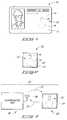
- FIG. 1is a front view of an employee badge providing the device of this invention.
- FIG. 2is a front view of a radio frequency identification tag of this invention.
- FIG. 3is a block diagram of an electronic identification system illustrating communication between an interrogator unit and the tag of FIG. 2 .
- FIG. 4is a plan view of a monolithic semiconductor integrated circuit utilized in the device of FIG. 2 illustrating an integrated circuitry layout configured for use with a hybrid antenna.
- FIG. 5is an alternative construction of a monolithic semiconductor integrated circuit from that depicted in FIG. 4 , wherein the antenna is formed directly on the integrated circuit.
- FIG. 6is an enlarged partial view taken generally from encircled region 6 of FIG. 4 depicting a discretely slit portion.
- FIG. 7is an enlarged partial view taken generally from encircled region 7 of FIG. 4 depicting a stepwise removed portion.
- FIG. 8is a diagrammatic side sectional view illustrating mounting of an integrated circuit, battery and antenna to the tag device of FIG. 2 .
- FIG. 9is a diagrammatic side sectional view illustrating an alternative wire bonding technique for mounting the integrated circuit, battery and antenna to the tag device of FIG. 2 .
- FIG. 10is a diagrammatic side sectional view illustrating another alternative mounting technique using tape automated bonding (TAB) of leads to electrically bond the integrated circuit, battery and antenna together on the tag device of FIG. 2 .
- TABtape automated bonding
- an adjustable radio frequency data communications devicecomprises a monolithic semiconductor integrated circuit having integrated circuitry; interrogation receiving circuitry provided on the monolithic integrated circuit forming at least part of the integrated circuitry and configured to receive an interrogation signal from the interrogator unit; an antenna electrically coupled to the interrogation receiving circuitry and configured to communicate with the remote interrogator unit; a power source electrically coupled to the integrated circuitry and configured to generate operating power for the communications device; and at least one of the antenna and the interrogation receiving circuitry having reconfigurable electrical characteristics, the electrical characteristics being reconfigurable to selectively tune the at least one of the antenna and the interrogation receiving circuitry within a range of tuned and detuned states to realize a desired receiver sensitivity of the communications device.
- an adjustable radio frequency data communications devicecomprises: a printed circuit board having printed circuitry; interrogation receiving circuitry provided on the circuit board electrically coupled to the integrated circuitry and configured to receive an interrogation signal from the interrogator unit; an antenna electrically coupled to the interrogation receiving circuitry, the antenna configured to receive the interrogation signal from the interrogator unit and deliver the interrogation signal to the interrogation receiving circuitry; a power source electrically coupled to the printed circuitry and configured to generate operating power for the communications device; and at least one of the antenna and the interrogation receiving circuitry having reconfigurable electrical characteristics, the electrical characteristics being reconfigurable to selectively tune at least one of the antenna and the interrogation receiving circuitry within a range of tuned and detuned states to realize a desired detuned receiver sensitivity of the communications device.
- a method of adapting a radio frequency data communications device for use with a remote interrogator unitcomprises the steps of: providing transponder circuitry; providing an antenna electrically coupled to the transponder circuitry for communicating with a remote interrogator unit; and selectively tuning at least one of the antenna and the transponder circuitry within a range of tuned and detuned states to realize a desired receiver sensitivity responsive to an interrogation signal transmitted by the interrogator unit.
- FIG. 1illustrates an employee identification badge 10 embodying this invention.
- the badge of this inventionin one embodiment has a radio-frequency data communication device 12 laminated to a back face of a plastic card 11 , wherein the card forms the visible portion of the badge.
- the communication device 12is bonded to the back face of the card by embedding it within a thin bond line of epoxy-based material.
- the communication device 12is embedded into the plastic card 11 .
- the communication device 12has an antenna 14 that is electrically connected with a transponder silicon-chip integrated circuit 16 to form a transmitting and receiving device.
- the devicehas a battery 18 that is electrically connected to the integrated circuit in order to power the device when it is transmitting and receiving radio-frequency (RF) signals between itself and another device.
- RFradio-frequency
- the front face of the badgealso has visual identification features including an employee photograph as well as identifying text.
- the antenna 14is constructed and arranged to form a folded dipole antenna, consisting of a continuous conductive path, or loop of microstrip.
- the terminal ends of the loopeach form a conductive lead similar to leads 37 in FIG. 4 that electrically interconnects with a transponder circuit 30 on the integrated circuit 16 , as depicted in use in an alternative embodiment in FIG. 4 and discussed in greater detail below.
- the antennacan be constructed as a continuous loop antenna 22 , as depicted in FIGS. 2-3 and discussed in greater detail below.
- the battery 18is a thin profile button-type battery forming a small, thin energy cell more commonly utilized in watches and small electronic devices requiring a thin profile.
- a conventional button-type batteryhas a pair of electrodes, an anode formed by one face and a cathode formed by an opposite face.
- Exemplary button-type batteriesare disclosed in several pending U.S. patent applications including U.S. patent application Ser. No. 08/205,957, titled “Button-Type Battery Having Bendable Construction and Angled Button-Type Battery”, listing Mark E. Tuttle and Peter M. Blonsky as inventors (now U.S. Pat. No. 5,432,027); and U.S. patent application Ser. No.
- FIG. 2depicts an alternative construction for a radio-frequency data communications device 12 ′ constructed as an identification postage stamp 20 .
- Device 12 ′has a semiconductor-based transponder integrated circuit 16 , a battery 18 , and an antenna 22 .
- the antennais constructed from a continuous piece of conductive microstrip configured in the shape of a square to form a loop antenna.
- the postage stampis formed from a thin sheet, or card 21 of plastic material having a thickness of about 0.005 inches, and a final width and height of about 1.25 inches.
- the device 12 ′is bonded to a back face of the plastic card by embedding it in a thin layer of non-conductive epoxy material. The final thickness is about 0.030 inches. Further details of the construction will be discussed below with reference to FIG. 8 .
- the integrated circuit 16 , antenna 22 , and battery 18form a transponder device capable of transmitting and receiving RF signals with a radio-frequency interrogator unit 26 , shown in FIG. 3 as radio-frequency communication system 24 .
- the interrogator unitincludes an antenna 28 , as well as dedicated transmitting and receiving circuitry, similar to that implemented on integrated circuit 16 .
- One example of an interrogator unit implemented in combination with a transponder unitis disclosed in U.S. Pat. No. 4,857,893, hereby incorporated by reference.
- the interrogator unittransmits an interrogation signal 27 via antenna 28 .
- the transponder device 12 ′in this case stamp 20 , receives the incoming interrogation signal with antenna 22 .
- device 12 ′Upon receiving signal 27 , device 12 ′ preferably responds by generating and transmitting a responsive signal 29 .
- the responsive signal 29is encoded with unique information that uniquely identifies, or labels the stamp 20 , as well as any object on which the stamp is affixed.
- such a system 24can be used, for example, to monitor large warehouse inventories having many unique products needing individual discrimination to determine the presence of particular items within a large lot of products.
- a significant problemis posed by such implementations where a battery is used to supply power to the devices since each time an interrogation signal 27 is received, each device within receiving range of the signal will “wake up”, thereby consuming valuable power and reducing the life of the battery.
- the life of the deviceis also reduced commensurately since the battery is preferably permanently sealed inside either a badge 10 , a stamp 20 , or some other similar tag.
- One reason for sealing the battery within the tagis to simplify the design and construction, as well as to reduce the cost of producing the tag. Another is to seal the battery within the tag, thereby protecting it from moisture and contaminants. A third reason is to enhance the cosmetic appeal of the tag by eliminating the need for an access port or door otherwise necessary to insert and remove the battery. When the battery is discharged, the entire badge or stamp is then discarded. Hence, it is desirable to maximize the life of the battery by minimizing power consumption.
- the transponder device 12 ′is electrically powered by a battery 18 .
- device 12 ′goes into a sleep, or battery conserving stand-by mode of operation during long time periods where no interrogation signal 27 is received by the device.
- a low current circuitperiodically wakes up the device every sixteen milliseconds in order to check if any RF signals are being detected by the device. Upon detection of such signals, the device fully wakes up, returning it to a full power operating mode.
- the receiver sensitivity of the transponder device 12 ′is preferably tuned over a range of tuned and detuned states in order to modify the ability of the device to detect signal 27 , and therefore adjust the tendency for the device to wake up.
- the receiver sensitivity of the deviceis adjusted by reconfiguring the electrical characteristics (circuitry) of the circuit forming the transponder device.
- One way to adjust the receiver sensitivityis to adjust the sensitivity, or impedance of the antenna.
- Another wayis to adjust or switch in different circuit elements in the transponder device, thereby realizing different circuit configurations.
- the transmitting sensitivity for the transponder devicecan be adjusted in essentially the same manner. Techniques of this invention for adjusting the transmitting and receiving sensitivities for an antenna will be discussed below with reference to implementations depicted generally in FIGS. 4-7 . Techniques of this invention for adjusting the transmitting and receiving sensitivities for circuit elements of the transponder device will also be discussed below with reference to implementations depicted generally in FIGS. 4 and 5 .
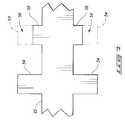
- FIG. 4depicts the particular construction of integrated circuit 16 as implemented on the devices 10 and 20 of FIGS. 1 and 2 , respectively.
- the integrated circuitis formed from a single monolithic silicon chip construction wherein the integrated circuit, or wafer receives an array of transponder circuits 30 , logic circuits 32 , memory control logic circuits 34 , and a programmable memory array 36 according to standard semiconductor wafer processing steps.
- pairs of conductive die pads 38 and 40are formed on the integrated circuit in order to facilitate electrical connection with the antenna 22 and battery 18 , respectively.
- circuits 30are electrically coupled with the conductive die pads 38 and 40 by way of sections of conductive microstrip 39 and 41 , respectively.
- antenna 22is depicted in electrically conductive and bonded relationship with pads 38 via legs 37 , although the preferred assembly technique, illustrated in FIG. 8 and discussed below, involves a flip-chip epoxy bonding technique wherein the antenna 22 is actually printed onto the back face of the plastic card 21 forming the postage stamp 20 , after which the integrated circuit is bonded to the antenna, as well as to the battery, using a conductive epoxy.
- FIG. 4depicts the relationship of the transponder circuits 30 relative to antenna 22 which electrically connects directly to the transponder circuits, and the battery (not illustrated in this Figure), and which also electrically connects directly to the transponder circuits.
- the logic circuits 32 , the memory control logic 34 , and the programmable memory array 36electrically connect with the transponder circuits 30 .
- battery 18once electrically connected to pads 40 , powers all of the circuits 30 - 36 .
- transceiving sensitivityincludes transmitter and receiver sensitivity.
- the transmitting sensitivity or the receiving sensitivitycan be tuned.
- separate transmitting and receiving antennascan be independently tuned.
- a receive antenna and a separate backscatter transmit antennacan be used, and for one case, just the receive antenna is trimmed in order to tune it.
- tuningrefers to either tuning or detuning a radio-frequency transponder device.
- adjustment of the antenna impedance relative to the impedance of the transponder circuitsimparts a tuning to the combined electrical circuit. For example, when the antenna impedance matches the transponder circuit impedance and the two are connected in series, the circuit is optimally tuned. Similarly, various degrees of impedance mis-matching produce corresponding levels of detuning.
- transponder circuit 30logic circuits 32 and memory control logic 34 are implemented as a combination of hardware circuit elements and software.
- the softwareis implemented in the programmable memory array 36 .
- FIG. 6depicts one method for tuning the antenna 22 of FIG. 4 , wherein a portion of conductive microstrip forming the antenna is selectively removed along each edge with a laser, forming a transverse slit 52 .
- the resulting step-width change in the microstrip antennacauses a change in impedance, thereby changing the tuned state of the antenna from the originally produced state.
- a large lot of identical antennascan be mass produced at the factory, after which the antennas can be laser trimmed to create batches of antennas having tailored tuned characteristics, e.g. specific receiving sensitivities.
- the antenna 22 of FIGS. 4 and 6 - 7is printed onto the back side of card 21 , forming the microstrip loop antenna.
- the antennacan be silk screened onto the card with a conductive polymer thick film.
- a conductive silver filled epoxycan be used. Further details of this construction will be provided below when describing FIG. 8 .
- the antennacan be formed from a separate piece of conductive material, for example, from a piece of wire or conductive ribbon that is glued to the back of the card.
- FIG. 7illustrates another method for tuning the antenna of FIG. 4 , wherein the microstrip antenna is produced with widened regions, forming laterally extending pairs of stubs 54 .
- the pairs of stubsimpart changes in the impedance of the resulting antenna 22 .
- the stubsfacilitate laser removal of portions 56 , leaving enshortened stubs 58 .
- the impedance of the antenna 22can be changed, thereby tuning the antenna based on the amount of conductive material removed from portions 56 , as well as from the number of portions 56 removed from an array along the microstrip.
- FIG. 5illustrates a third method for tuning an antenna on a semiconductor transponder integrated circuit 46 having a coil-shaped antenna 48 formed directly on the integrated circuit in the form of microstrip with one of several presently known standard semiconductor deposition techniques.
- Antenna 48is preferably formed with a conductive bridge line 50 similar to conductive microstrip lines 39 and 41 that shunts conduction between adjacent coils of the antenna.
- the conductive bridge line 50can be removed, either mechanically or by laser trimming in order to tune the antenna to a desired state.
- the effective conducting length of the antennais modified, realizing one or several possible length antennas defined by the number and size of each coil, and any remaining portion of the bridge.
- an insulating layer of materialis deposited on top of conductive leads 41 during manufacture in order to insulate the leads from shorting out coils on the antenna 48 .
- numeral 46 of FIG. 5can represent a printed circuit board having integrated circuitry and hybrid circuit elements attached to the circuitry, forming the circuits 30 - 36 and antenna 48 .
- the inventive contributionconsists of intentionally detuning the transponder sensitivity of the tag device.
- the receiver sensitivity of the devicecan be modified by electrically modifying the receiver circuit on the integrated circuit itself.
- the receiver circuitcan be modified by electrically modifying the receiver circuit on the integrated circuit itself.
- a plurality of parallel circuits, each having a different impedance or amplification factorare alternately switched into an electrically conductive configuration within the transponder circuit.
- different fixed matching networkscan be alternately switched into connection within the circuit.
- One way to achieve the switchingis to provide temporary contact connections on the integrated circuit (not shown) for forming a temporary electrical connection at the factory, allowing for factory setup of one of the matching networks within circuits 30 to realize a specific tuned condition for a transponder device 12 .
- an array of resistive and/or capacitive elementscan be provided on parallel circuit legs, each configured with a physical switch for connecting and disconnecting the leg from the transponder circuit, such that each leg imparts a different circuit impedance, and hence, a different tuning.
- Another wayis to implement a software switching routine that allows either factory or user switching of different circuit implementations within the transponder circuits 30 , with actual circuit elements or with a software routine implemented in memory 36 and triggered by interrogation signals 27 received from the interrogator unit 26 depicted in FIG. 3 to realize a software-based circuit implementation.
- each circuit legcan have an amplifier configured to impart a distinct tuning level to the circuit when switched into connection with the circuit.
- the transponder circuit realized on the integrated circuitis modified to change the circuit impedance, thereby realizing a different receiving sensitivity for the device.
- the same techniquecan be used to tune the transmitting sensitivity.
- a hybrid elementsuch as a trim pot can be connected to the circuits 30 of the integrated circuit to allow adjustment, or tuning of the circuits by either a manufacturer or a user.
- Another reason for providing a tuning feature on RF data communication devices such as tags 10 and 20is to allow a manufacturer to produce large lots of identical integrated circuits and antennas, thereby enabling a cost savings resulting from large scales of production. Furthermore, by producing runs of identical devices, variables can be better controlled, enabling production of more uniform product which increases the amount of acceptable yield. After manufacture, the integrated circuits and/or antennas can be tuned by one of the techniques of this invention in order to create tuned tag devices having particular receiving and/or transmitting sensitivities.
- stamps 20can be mass produced, then the antenna 22 can be tuned to impart one of three receiver sensitivities of 5 feet, 20 feet or 100 feet.
- One customermay need tags having only one of the above operating ranges. Another customer may need all three, placing the least sensitive tags on objects where frequent inadvertent wake up calls from an interrogator are undesirable.
- the interrogatoris positioned within the five foot range in order to activate the device, resulting in a responsive signal 29 . Additional applications requiring employee badges 10 having varying degrees of receiver sensitivity can easily be envisioned.
- FIG. 8shows an exemplary technique for assembling the postage stamp 20 .
- the same techniquecan be used to assemble the badge 10 or any other similarly constructed tag having a rigid support or substrate similar to plastic cards 11 and 21 .
- antenna 22 , conductive pads 66 - 68 and conductive microstrip leads 69are printed onto a back face of the sheet of material.
- the above elements, or conductorsare simultaneously printed onto the back of a large sheet of plastic material with a conductive silver printed thick film.
- the cardsare individually separated (after complete assembly), or cut from the sheet.
- Pads 66form enlarged connection points for the antenna 22 , in contrast to the pads 37 formed directly from the end portions of the antenna 22 in FIG. 4 .
- the sheetis positioned front face down onto a rigid support plate 62 .
- integrated circuit, or chip 16is mounted to pads 66 and 67 with conductive beads of epoxy 70 .
- the battery 18is bonded along its bottom face with a bead of conductive epoxy 70 to the sheet, on each card, after which conductive epoxy 70 is used to electrically connect the opposite terminal or top of the battery with a corresponding conductive die pad 68 .
- the antennas and electrical componentsare then electrically tested and/or trimmed, if necessary, prior to being encapsulated.
- a bead of hot melt glue forming a dam 64 sized to conform generally to the outer peripheral shape of the sheet 21is placed over the back of the card.
- the damfunctions as an outer template while a thin layer of non-conductive epoxy (not shown) is applied to the back of the sheet 21 , preferably hermetically sealing in (or encapsulating) the integrated circuit, antenna and battery.
- the sheetis separated, or singulated to form separate cards. In this manner, a large number of devices are assembled onto a single sheet, after which they are separated.
- the thin coat of epoxyconsists of a coating, barely thick enough to cover over the components forming the device 12 ′.
- the above technique for mounting integrated circuit 16 to card 21consists of a flip-chip mounting technique.
- a flip-chip mounting techniqueis disclosed in U.S. patent application Ser. No. 08/166,747, titled “Process of Manufacturing an Electrical Bonding Interconnect Having a Metal Bond Pad Portion and Having a Conductive Epoxy Portion Comprising an Oxide Reducing Agent”, listing Rickie C. Lake and Mark E. Tuttle as inventors (now U.S. Pat. No. 5,480,834), and herein incorporated by reference.
- FIG. 9depicts an alternative method for electrically connecting the integrated circuit 16 to the antenna 22 and battery 18 with conductive wires.
- the integrated circuit 16is adhesively bonded to the back face of card 21 , between the bonding pads 37 of the antenna 22 and the battery 18 .
- the battery 18is bonded along a bottom face to pad 68 .
- a wire 76 and 78is used to connect each of the integrated circuit pads 38 and 40 , respectively, to antenna bonding pads 37 and the top and bottom of battery 18 , respectively.
- each wireis soldered to the associated pads and battery.
- the wirescan be electrically mounted using conductive epoxy.
- FIG. 10depicts another alternative method for electrically connecting the integrated circuit 16 to the antenna 22 and battery 18 with conductive leads 80 and 82 , respectively.
- one end of each lead 80 and 82is bonded to a pad 38 and 40 on the integrated circuit, respectively, and the other end is bonded to pad 37 , and pad 67 and the top of battery 18 , respectively, using conductive epoxy.
- the leadscan be soldered at each end to the respective components.
- the batteryis bonded to the back face of card 21 by applying conductive adhesive between the battery and pad 68 .
- the integrated circuitis bonded along a bottom face to the back side of card 21 .
Landscapes
- Engineering & Computer Science (AREA)
- Physics & Mathematics (AREA)
- Radar, Positioning & Navigation (AREA)
- Remote Sensing (AREA)
- General Physics & Mathematics (AREA)
- Computer Networks & Wireless Communication (AREA)
- Theoretical Computer Science (AREA)
- Microelectronics & Electronic Packaging (AREA)
- Computer Hardware Design (AREA)
- Health & Medical Sciences (AREA)
- Toxicology (AREA)
- Electromagnetism (AREA)
- General Health & Medical Sciences (AREA)
- Artificial Intelligence (AREA)
- Computer Vision & Pattern Recognition (AREA)
- Condensed Matter Physics & Semiconductors (AREA)
- Power Engineering (AREA)
- Credit Cards Or The Like (AREA)
- Near-Field Transmission Systems (AREA)
Abstract
Description
Claims (49)
Priority Applications (1)
| Application Number | Priority Date | Filing Date | Title |
|---|---|---|---|
| US11/607,251US7884724B2 (en) | 1996-07-30 | 2006-12-01 | Radio frequency data communications device with selectively removable antenna portion and method |
Applications Claiming Priority (7)
| Application Number | Priority Date | Filing Date | Title |
|---|---|---|---|
| US2332196P | 1996-07-30 | 1996-07-30 | |
| US08/708,164US6466131B1 (en) | 1996-07-30 | 1996-08-29 | Radio frequency data communications device with adjustable receiver sensitivity and method |
| US09/961,204US6509837B1 (en) | 1996-07-30 | 2001-09-21 | Radio frequency data communications device with adjustable receiver sensitivity and method |
| US10/315,427US6781508B2 (en) | 1996-07-30 | 2002-12-09 | Radio frequency data communications device with adjustable receiver sensitivity and method |
| US10/696,102US7345575B2 (en) | 1996-07-30 | 2003-10-28 | Radio frequency data communications device with adjustable receiver sensitivity and method |
| US11/370,455US7283035B2 (en) | 1996-07-30 | 2006-03-07 | Radio frequency data communications device with selectively removable antenna portion and method |
| US11/607,251US7884724B2 (en) | 1996-07-30 | 2006-12-01 | Radio frequency data communications device with selectively removable antenna portion and method |
Related Parent Applications (1)
| Application Number | Title | Priority Date | Filing Date |
|---|---|---|---|
| US11/370,455ContinuationUS7283035B2 (en) | 1996-07-30 | 2006-03-07 | Radio frequency data communications device with selectively removable antenna portion and method |
Publications (2)
| Publication Number | Publication Date |
|---|---|
| US20070075837A1 US20070075837A1 (en) | 2007-04-05 |
| US7884724B2true US7884724B2 (en) | 2011-02-08 |
Family
ID=26696980
Family Applications (7)
| Application Number | Title | Priority Date | Filing Date |
|---|---|---|---|
| US08/708,164Expired - LifetimeUS6466131B1 (en) | 1996-07-30 | 1996-08-29 | Radio frequency data communications device with adjustable receiver sensitivity and method |
| US09/961,204Expired - LifetimeUS6509837B1 (en) | 1996-07-30 | 2001-09-21 | Radio frequency data communications device with adjustable receiver sensitivity and method |
| US10/315,427Expired - Fee RelatedUS6781508B2 (en) | 1996-07-30 | 2002-12-09 | Radio frequency data communications device with adjustable receiver sensitivity and method |
| US10/696,102Expired - Fee RelatedUS7345575B2 (en) | 1996-07-30 | 2003-10-28 | Radio frequency data communications device with adjustable receiver sensitivity and method |
| US11/370,455Expired - Fee RelatedUS7283035B2 (en) | 1996-07-30 | 2006-03-07 | Radio frequency data communications device with selectively removable antenna portion and method |
| US11/607,251Expired - Fee RelatedUS7884724B2 (en) | 1996-07-30 | 2006-12-01 | Radio frequency data communications device with selectively removable antenna portion and method |
| US11/968,561Expired - Fee RelatedUS8624711B2 (en) | 1996-07-30 | 2008-01-02 | Radio frequency identification device operating methods, radio frequency identification device configuration methods, and radio frequency identification devices |
Family Applications Before (5)
| Application Number | Title | Priority Date | Filing Date |
|---|---|---|---|
| US08/708,164Expired - LifetimeUS6466131B1 (en) | 1996-07-30 | 1996-08-29 | Radio frequency data communications device with adjustable receiver sensitivity and method |
| US09/961,204Expired - LifetimeUS6509837B1 (en) | 1996-07-30 | 2001-09-21 | Radio frequency data communications device with adjustable receiver sensitivity and method |
| US10/315,427Expired - Fee RelatedUS6781508B2 (en) | 1996-07-30 | 2002-12-09 | Radio frequency data communications device with adjustable receiver sensitivity and method |
| US10/696,102Expired - Fee RelatedUS7345575B2 (en) | 1996-07-30 | 2003-10-28 | Radio frequency data communications device with adjustable receiver sensitivity and method |
| US11/370,455Expired - Fee RelatedUS7283035B2 (en) | 1996-07-30 | 2006-03-07 | Radio frequency data communications device with selectively removable antenna portion and method |
Family Applications After (1)
| Application Number | Title | Priority Date | Filing Date |
|---|---|---|---|
| US11/968,561Expired - Fee RelatedUS8624711B2 (en) | 1996-07-30 | 2008-01-02 | Radio frequency identification device operating methods, radio frequency identification device configuration methods, and radio frequency identification devices |
Country Status (3)
| Country | Link |
|---|---|
| US (7) | US6466131B1 (en) |
| AU (1) | AU3968497A (en) |
| WO (1) | WO1998005171A1 (en) |
Cited By (7)
| Publication number | Priority date | Publication date | Assignee | Title |
|---|---|---|---|---|
| US20090051538A1 (en)* | 2004-06-18 | 2009-02-26 | Infineon Technologies Ag | Transceiver device |
| US20090184824A1 (en)* | 2008-01-22 | 2009-07-23 | Ian James Forster | RFID Tag with a Reduced Read Range |
| US8169373B2 (en)* | 2008-09-05 | 2012-05-01 | Apple Inc. | Antennas with tuning structure for handheld devices |
| US20130049933A1 (en)* | 2011-08-25 | 2013-02-28 | Elwha LLC, a limited liability company of the State of Delaware | Systems, devices, methods, and admixtures including interrogators and interrogation of tags for indication of food attributes |
| US8695884B2 (en) | 2011-08-25 | 2014-04-15 | Michael H. Baym | Systems, devices, admixtures, and methods including transponders for indication of food attributes |
| US20170132504A1 (en)* | 2015-11-06 | 2017-05-11 | Bank Of America Corporation | Radio Frequency Identification Activation |
| US10958661B2 (en) | 2018-11-28 | 2021-03-23 | Bank Of America Corporation | Multi-layer authentication system with selective level access control |
Families Citing this family (120)
| Publication number | Priority date | Publication date | Assignee | Title |
|---|---|---|---|---|
| US8280682B2 (en)* | 2000-12-15 | 2012-10-02 | Tvipr, Llc | Device for monitoring movement of shipped goods |
| US6466131B1 (en) | 1996-07-30 | 2002-10-15 | Micron Technology, Inc. | Radio frequency data communications device with adjustable receiver sensitivity and method |
| US5970398A (en) | 1996-07-30 | 1999-10-19 | Micron Communications, Inc. | Radio frequency antenna with current controlled sensitivity |
| MY119951A (en) | 1998-12-09 | 2005-08-30 | Shell Int Research | Transponder communications system |
| US8140658B1 (en)* | 1999-10-06 | 2012-03-20 | Borgia/Cummins, Llc | Apparatus for internetworked wireless integrated network sensors (WINS) |
| FR2802710B1 (en)* | 1999-12-16 | 2002-05-17 | Gemplus Card Int | RADIO FREQUENCY ANTENNA FOR DEVICE FOR QUERYING OBJECTS CARRYING A RADIO FREQUENCY ANTENNA ASSOCIATED WITH AN ELECTRIC CIRCUIT |
| DE10012967A1 (en)* | 2000-03-16 | 2001-09-20 | Andreas Plettner | Transponder used in radio frequency identification system, includes coupling elements connected to chip surface, and structurally designed to act as dipole antenna and disk capacitor |
| US6806812B1 (en) | 2000-04-26 | 2004-10-19 | Micron Technology, Inc. | Automated antenna trim for transmitting and receiving semiconductor devices |
| US6951596B2 (en) | 2002-01-18 | 2005-10-04 | Avery Dennison Corporation | RFID label technique |
| US7017822B2 (en)* | 2001-02-15 | 2006-03-28 | Integral Technologies, Inc. | Low cost RFID antenna manufactured from conductive loaded resin-based materials |
| US20040217472A1 (en)* | 2001-02-16 | 2004-11-04 | Integral Technologies, Inc. | Low cost chip carrier with integrated antenna, heat sink, or EMI shielding functions manufactured from conductive loaded resin-based materials |
| US7142811B2 (en)* | 2001-03-16 | 2006-11-28 | Aura Communications Technology, Inc. | Wireless communication over a transducer device |
| JP2002338013A (en)* | 2001-05-15 | 2002-11-27 | Ge Medical Systems Global Technology Co Llc | Stock control seal, stock control controller, and stock control system |
| TWI287317B (en)* | 2001-08-23 | 2007-09-21 | Asustek Comp Inc | Antenna module combining electrodes of differential-type circuit |
| DE10151440C1 (en)* | 2001-10-18 | 2003-02-06 | Siemens Ag | Organic electronic component for implementing an encapsulated partially organic electronic component has components like a flexible foil as an antenna, a diode or capacitor and an organic transistor. |
| US6809646B1 (en)* | 2001-12-06 | 2004-10-26 | Applied Wireless Identifications Group, Inc. | Thin implantable RFID transponder suitable for use in an identification badge |
| US7187288B2 (en)* | 2002-03-18 | 2007-03-06 | Paratek Microwave, Inc. | RFID tag reading system and method |
| WO2003091924A1 (en)* | 2002-04-24 | 2003-11-06 | Sk Telecom Co., Ltd | Mobile terminal with user identification card including personal finance-related information and method of using a value-added mobile service through said mobile terminal |
| US6970089B2 (en)* | 2002-07-03 | 2005-11-29 | Battelle Memorial Institute K1-53 | Full-spectrum passive communication system and method |
| EP1394719B1 (en)* | 2002-09-02 | 2007-05-30 | EM Microelectronic-Marin SA | Adaptation of the transmission and receiving characteristic of a RFID reader dependent on the electromagnetic background noise |
| GB2393076A (en)* | 2002-09-12 | 2004-03-17 | Rf Tags Ltd | Radio frequency identification tag which has a ground plane not substantially larger than the area spanned by the patch antenna |
| SG106662A1 (en)* | 2002-11-15 | 2004-10-29 | Smartag S Pte Ltd | Rfid tag for an object having metallic portions, tag coupler and method thereof |
| GB2395626B (en)* | 2002-11-21 | 2006-05-10 | Hewlett Packard Co | A memory tag and a reader |
| EP1434159A3 (en)* | 2002-12-24 | 2005-01-19 | Matsushita Electric Industrial Co., Ltd. | Integrated antenna type non-contact IC card reader/writer |
| US7253735B2 (en) | 2003-03-24 | 2007-08-07 | Alien Technology Corporation | RFID tags and processes for producing RFID tags |
| JP2006524402A (en)* | 2003-04-21 | 2006-10-26 | シンボル テクノロジーズ インコーポレイテッド | Method for optimizing the design and implementation of RFID tags |
| ATE530998T1 (en)* | 2003-07-07 | 2011-11-15 | Avery Dennison Corp | RFID DEVICE WITH CHANGEABLE CHARACTERISTICS |
| US7398054B2 (en) | 2003-08-29 | 2008-07-08 | Zih Corp. | Spatially selective UHF near field microstrip coupler device and RFID systems using device |
| US6999028B2 (en)* | 2003-12-23 | 2006-02-14 | 3M Innovative Properties Company | Ultra high frequency radio frequency identification tag |
| JP4328705B2 (en)* | 2004-02-27 | 2009-09-09 | 均 北吉 | RFID tag device |
| US7268687B2 (en)* | 2004-03-23 | 2007-09-11 | 3M Innovative Properties Company | Radio frequency identification tags with compensating elements |
| US7132946B2 (en)* | 2004-04-08 | 2006-11-07 | 3M Innovative Properties Company | Variable frequency radio frequency identification (RFID) tags |
| US20050237241A1 (en)* | 2004-04-27 | 2005-10-27 | Garber Richard S | Antenna for radio frequency identification reader |
| US8596532B2 (en)* | 2004-06-10 | 2013-12-03 | Zih Corp. | Apparatus and method for communicating with an RFID transponder |
| US20060000914A1 (en)* | 2004-06-30 | 2006-01-05 | Chen Chien-Yuan | Memory card capable of wireless transmission |
| US20060012464A1 (en)* | 2004-07-01 | 2006-01-19 | Zvi Nitzan | Battery-assisted backscatter RFID transponder |
| US7431217B2 (en)* | 2004-07-15 | 2008-10-07 | Mastercard International Incorporated | Reference equipment for testing contactless payment devices |
| US7667572B2 (en)* | 2004-07-30 | 2010-02-23 | Reva Systems Corporation | RFID tag data acquisition system |
| KR101149633B1 (en)* | 2004-08-09 | 2012-05-25 | 산코루 가부시키가이샤 | Seal with ic tag and method of attaching the same |
| US7109867B2 (en)* | 2004-09-09 | 2006-09-19 | Avery Dennison Corporation | RFID tags with EAS deactivation ability |
| US7253734B2 (en)* | 2004-09-22 | 2007-08-07 | International Business Machines Corporation | System and method for altering or disabling RFID tags |
| US7277016B2 (en)* | 2004-09-22 | 2007-10-02 | International Business Machines Corporation | System and method for disabling RFID tags |
| US7500307B2 (en) | 2004-09-22 | 2009-03-10 | Avery Dennison Corporation | High-speed RFID circuit placement method |
| DE102004046865B4 (en)* | 2004-09-27 | 2018-01-25 | Infineon Technologies Ag | Identification data carrier, reading device, identification system and method for operating an identification system |
| US7352056B2 (en)* | 2004-10-13 | 2008-04-01 | Advanced Semiconductor Engineering, Inc. | Semiconductor package structure with microstrip antennan |
| US7196626B2 (en)* | 2005-01-28 | 2007-03-27 | Wha Yu Industrial Co., Ltd. | Radio frequency identification RFID tag |
| US7545272B2 (en) | 2005-02-08 | 2009-06-09 | Therasense, Inc. | RF tag on test strips, test strip vials and boxes |
| US7471260B2 (en)* | 2005-02-14 | 2008-12-30 | Panasonic Corporation | Semiconductor memory module having built-in antenna |
| US7515051B2 (en) | 2005-02-25 | 2009-04-07 | Datalogic Mobile, Inc. | RFID antenna system having reduced orientation sensitivity |
| EP1872310A2 (en)* | 2005-03-07 | 2008-01-02 | Sensormatic Electronics Corporation | Automated tuning method for rfid labels |
| US7623034B2 (en) | 2005-04-25 | 2009-11-24 | Avery Dennison Corporation | High-speed RFID circuit placement method and device |
| US7728713B2 (en)* | 2005-05-06 | 2010-06-01 | Intelleflex Corporation | Accurate persistent nodes |
| US7714726B2 (en) | 2005-05-06 | 2010-05-11 | Dominic M. Kotab | Semi-transparent RFID tags |
| US20080272890A1 (en)* | 2005-06-30 | 2008-11-06 | Zvi Nitzan | Battery-assisted backscatter RFID transponder |
| US20090045916A1 (en)* | 2005-06-30 | 2009-02-19 | Zvi Nitzan | Battery-assisted backscatter RFID transponder |
| US7898391B2 (en)* | 2005-07-01 | 2011-03-01 | Trimble Navigation Limited | Multi-reader coordination in RFID system |
| WO2007029296A1 (en)* | 2005-09-02 | 2007-03-15 | Fujitsu Limited | Rf tag and method for manufacturing rf tag |
| US7750862B2 (en)* | 2005-11-10 | 2010-07-06 | Nxp B.V. | Broadband antenna for a transponder of a radio frequency identification system |
| US7555826B2 (en) | 2005-12-22 | 2009-07-07 | Avery Dennison Corporation | Method of manufacturing RFID devices |
| US8786510B2 (en) | 2006-01-24 | 2014-07-22 | Avery Dennison Corporation | Radio frequency (RF) antenna containing element and methods of making the same |
| US20070188327A1 (en)* | 2006-02-16 | 2007-08-16 | Ncr Corporation | Radio frequency device |
| BRPI0605714B1 (en)* | 2006-03-07 | 2018-06-26 | José Gouveia Abrunhosa Jorge | DEVICE AND PROCESS FOR DETECTION OF MAGNETIC MATERIALS IN ELECTROMAGNETIC TECHNOLOGY ANTI-THEFT SYSTEMS |
| KR100797172B1 (en)* | 2006-08-08 | 2008-01-23 | 삼성전자주식회사 | Loop antenna with integral matching circuit |
| US20080055045A1 (en)* | 2006-08-31 | 2008-03-06 | 3M Innovative Properties Company | Rfid tag including a three-dimensional antenna |
| JP2008092198A (en)* | 2006-09-29 | 2008-04-17 | Renesas Technology Corp | Rfid label tag, and its manufacturing method |
| US20080084311A1 (en)* | 2006-10-06 | 2008-04-10 | Texas Instruments | Inductance enhancement by magnetic material introduction |
| WO2008053789A1 (en)* | 2006-10-31 | 2008-05-08 | Semiconductor Energy Laboratory Co., Ltd. | Semiconductor device |
| WO2008084353A1 (en)* | 2007-01-08 | 2008-07-17 | Nxp B.V. | Transponders and methods for operating a transponder |
| US7997495B2 (en)* | 2007-03-15 | 2011-08-16 | James Neil Rodgers | Precisely tuned RFID antenna |
| US7825867B2 (en)* | 2007-04-26 | 2010-11-02 | Round Rock Research, Llc | Methods and systems of changing antenna polarization |
| US8044804B1 (en)* | 2007-06-01 | 2011-10-25 | Hewlett-Packard Development Company, L. P. | Localizing a tag using variable signal range |
| US7936268B2 (en)* | 2007-08-31 | 2011-05-03 | Round Rock Research, Llc | Selectively coupling to feed points of an antenna system |
| US8289163B2 (en)* | 2007-09-27 | 2012-10-16 | 3M Innovative Properties Company | Signal line structure for a radio-frequency identification system |
| US20090085750A1 (en)* | 2007-09-27 | 2009-04-02 | 3M Innovative Properties Company | Extended RFID tag |
| US8717244B2 (en)* | 2007-10-11 | 2014-05-06 | 3M Innovative Properties Company | RFID tag with a modified dipole antenna |
| US8149108B2 (en)* | 2007-11-14 | 2012-04-03 | Stryker Corporation | System and method for automatically powering on and synchronizing a wireless remote console to a central control unit so as to allow remote control of a medical device |
| US9108434B2 (en)* | 2007-12-18 | 2015-08-18 | Zih Corp. | RFID near-field antenna and associated systems |
| JP5188167B2 (en) | 2007-12-20 | 2013-04-24 | 株式会社ユニバーサルエンターテインメント | Paper sheet processing equipment |
| US8350673B2 (en)* | 2008-01-31 | 2013-01-08 | Neology, Inc. | Methods and apparatus for preserving privacy in an RFID system |
| US10262167B2 (en) | 2008-01-31 | 2019-04-16 | Smartrac Technology Fletcher, Inc. | Detachable radio frequency identification switch tag |
| US7982616B2 (en)* | 2008-02-14 | 2011-07-19 | 3M Innovative Properties Company | Radio frequency identification (RFID) tag including a three-dimensional loop antenna |
| US8086190B2 (en)* | 2008-03-27 | 2011-12-27 | Broadcom Corporation | Method and system for reconfigurable devices for multi-frequency coexistence |
| TW201001958A (en) | 2008-04-29 | 2010-01-01 | Odin Technologies Inc | Method and apparatus for a deployable radio-frequency identification portal system |
| US8115637B2 (en) | 2008-06-03 | 2012-02-14 | Micron Technology, Inc. | Systems and methods to selectively connect antennas to receive and backscatter radio frequency signals |
| US8284028B2 (en)* | 2008-08-14 | 2012-10-09 | Icopal Danmark A/S | Method of manufacturing an identifiable roofing product including a roofing product and a process plant for carrying out the method |
| WO2010039550A2 (en)* | 2008-09-23 | 2010-04-08 | Quantenna Communications, Inc. | Adjustable operational state wireless mimo |
| KR101567023B1 (en)* | 2008-12-11 | 2015-11-13 | 삼성전자주식회사 | Radio frequency identifier tag and method for forming the same |
| FR2947073A1 (en)* | 2009-06-19 | 2010-12-24 | St Microelectronics Rousset | ENERGY MANAGEMENT IN AN ELECTROMAGNETIC TRANSPONDER |
| US8633777B2 (en)* | 2009-12-01 | 2014-01-21 | Qualcomm Incorporated | Methods and apparatus for inductors with integrated passive and active elements |
| US8526935B2 (en)* | 2009-12-15 | 2013-09-03 | General Electric Company | Appliance demand response antenna design for improved gain within the home appliance network |
| US9508213B2 (en) | 2010-03-22 | 2016-11-29 | Dominic M. Kotab | Systems and methods of reading gaming chips and other stacked items |
| WO2011159727A1 (en) | 2010-06-14 | 2011-12-22 | Avery Dennison Corporation | Method, system and apparatus for making short run radio frequency identification tags and labels |
| WO2014134157A1 (en) | 2013-02-26 | 2014-09-04 | Quake Global, Inc. | Methods and apparatus for automatic identification wristband |
| WO2012102674A1 (en)* | 2011-01-28 | 2012-08-02 | Siemens Medical Instruments Pte Ltd | A controller arrangement configured to remotely control an electronic device |
| DE202011002173U1 (en)* | 2011-02-01 | 2011-06-01 | ASTRA Gesellschaft für Asset Management mbH & Co. KG, 30890 | detection microchip |
| US10102685B2 (en) | 2011-05-06 | 2018-10-16 | Neology, Inc. | Self declaring device for a vehicle using restrict traffic lanes |
| US10885418B2 (en) | 2011-05-06 | 2021-01-05 | Neology, Inc. | Detachable radio frequency identification switch tag |
| WO2012154605A2 (en) | 2011-05-06 | 2012-11-15 | Neology, Inc. | Rfid switch tag |
| US11948035B2 (en) | 2011-05-06 | 2024-04-02 | Neology, Inc. | RFID switch tag |
| FI125720B (en) | 2011-05-19 | 2016-01-29 | Tecnomar Oy | Procedure for the manufacture of electric bridges suitable for roll-to-roll mass production |
| BR112014008271B1 (en)* | 2011-10-10 | 2021-02-17 | Koninklijke Philips N.V. | docking station for wireless docking with a dockee in a shared radio spectrum environment, and method for providing a docking station |
| US9141903B2 (en)* | 2012-03-13 | 2015-09-22 | Symbol Technologies, Llc | Indicating ultrasonic data tag movement |
| WO2013188632A1 (en) | 2012-06-14 | 2013-12-19 | Dow Global Technologies Llc | Alkyl hyroxylamine compounds and their use for shortstopping free radical polymerizations |
| WO2014052212A1 (en) | 2012-09-28 | 2014-04-03 | Dow Global Technologies Llc | Alkyl hydroxylamine compounds and their use for shortstopping free radical polymerizations |
| US9841492B2 (en) | 2013-02-25 | 2017-12-12 | Quake Global, Inc. | Ceiling-mounted RFID-enabled tracking |
| US9559544B2 (en)* | 2013-03-15 | 2017-01-31 | Jay Marketing Associates, Inc. | Wireless interrogation and wireless charging of electronic devices |
| US10909440B2 (en) | 2013-08-22 | 2021-02-02 | Texas Instruments Incorporated | RFID tag with integrated antenna |
| EP2889635A1 (en) | 2013-12-24 | 2015-07-01 | Televic Healthcare NV | Localisation system |
| EP2889634B1 (en)* | 2013-12-24 | 2016-12-07 | Televic Healthcare NV | Localisation system |
| US20150382285A1 (en)* | 2014-06-26 | 2015-12-31 | Qualcomm Incorporated | Other radio access technology search inside a gsm tune-away gap in multi-sim devices |
| US9716318B2 (en) | 2014-10-22 | 2017-07-25 | Laird Technologies, Inc. | Patch antenna assemblies |
| JP6390418B2 (en)* | 2014-12-24 | 2018-09-19 | 株式会社ソシオネクスト | Semiconductor device, semiconductor device manufacturing method, and semiconductor device identification method |
| US20160307010A1 (en)* | 2015-04-16 | 2016-10-20 | Hand Held Products, Inc. | Systems and methods for tuning an antenna of a mobile computing device |
| US10750236B2 (en)* | 2015-04-23 | 2020-08-18 | The Nielsen Company (Us), Llc | Automatic content recognition with local matching |
| US11403506B2 (en) | 2015-05-21 | 2022-08-02 | Neology, Inc. | Detachable radio frequency identification switch tag |
| EP3298544B1 (en) | 2015-05-21 | 2022-11-09 | Smartrac Technology Fletcher, Inc. | Multi-frequency radio frequency identification tag |
| US9875382B2 (en)* | 2016-03-11 | 2018-01-23 | Utility Composites, Inc. | RFID tracking fastener |
| EP3343245A1 (en) | 2016-12-30 | 2018-07-04 | Televic Healthcare NV | False alarm avoidance system |
| WO2023062416A1 (en)* | 2021-10-14 | 2023-04-20 | Wiliot, LTD. | Techniques for wakeup in a low-power wireless device |
| US11889420B2 (en) | 2021-10-14 | 2024-01-30 | Wiliot, LTD. | Techniques for wakeup in a low-power wireless device |
Citations (115)
| Publication number | Priority date | Publication date | Assignee | Title |
|---|---|---|---|---|
| US3155954A (en) | 1962-06-15 | 1964-11-03 | Howard M Larrick | Automatic sensitivity control for sound actuated detection and alarm systems |
| US3810147A (en) | 1971-12-30 | 1974-05-07 | G Lichtblau | Electronic security system |
| US3955201A (en) | 1974-07-29 | 1976-05-04 | Crump Lloyd R | Radar randome antenna with switchable R.F. transparency/reflectivity |
| US3967202A (en) | 1974-07-25 | 1976-06-29 | Northern Illinois Gas Company | Data transmission system including an RF transponder for generating a broad spectrum of intelligence bearing sidebands |
| US4021705A (en) | 1975-03-24 | 1977-05-03 | Lichtblau G J | Resonant tag circuits having one or more fusible links |
| US4048564A (en) | 1976-01-26 | 1977-09-13 | Gleeson Jr Thomas Paul | Transceiver test device |
| US4075632A (en) | 1974-08-27 | 1978-02-21 | The United States Of America As Represented By The United States Department Of Energy | Interrogation, and detection system |
| US4167010A (en) | 1978-03-13 | 1979-09-04 | The United States Of America As Represented By The Secretary Of The Army | Terminated microstrip antenna |
| US4215341A (en) | 1977-01-19 | 1980-07-29 | Cole Martin T | Intrusion or movement detector |
| US4470047A (en) | 1982-02-04 | 1984-09-04 | Baker Industries, Inc. | Bidirectional, interactive fire detection system |
| US4486723A (en) | 1983-01-06 | 1984-12-04 | Rca Corporation | Diode switching system for a selectable impedance matching network |
| US4498076A (en) | 1982-05-10 | 1985-02-05 | Lichtblau G J | Resonant tag and deactivator for use in an electronic security system |
| US4560445A (en) | 1984-12-24 | 1985-12-24 | Polyonics Corporation | Continuous process for fabricating metallic patterns on a thin film substrate |
| US4572976A (en) | 1982-12-10 | 1986-02-25 | N.V. Nederlandsche Apparatenfabriek Nedap | Transponder for electromagnetic detection system with non-linear circuit |
| US4694283A (en) | 1981-10-30 | 1987-09-15 | Reeb Max E | Identification device in the form of a tag-like strip affixable to an article |
| US4724427A (en) | 1986-07-18 | 1988-02-09 | B. I. Incorporated | Transponder device |
| US4780724A (en) | 1986-04-18 | 1988-10-25 | General Electric Company | Antenna with integral tuning element |
| US4782342A (en)* | 1986-08-04 | 1988-11-01 | Walton Charles A | Proximity identification system with lateral flux paths |
| US4822990A (en) | 1985-11-29 | 1989-04-18 | Kabushiki Kaisha Toshiba | Admission control system having a transponder actuated by an inquiry signal |
| US4825220A (en) | 1986-11-26 | 1989-04-25 | General Electric Company | Microstrip fed printed dipole with an integral balun |
| US4827395A (en) | 1983-04-21 | 1989-05-02 | Intelli-Tech Corporation | Manufacturing monitoring and control systems |
| US4854328A (en) | 1987-03-23 | 1989-08-08 | Philip Pollack | Animal monitoring telltale and information system |
| US4856082A (en) | 1986-08-19 | 1989-08-08 | Pioneer Electronic Corporation | Reception sensitivity control system in a sweeping receiver |
| US4857893A (en) | 1986-07-18 | 1989-08-15 | Bi Inc. | Single chip transponder device |
| US4862160A (en) | 1983-12-29 | 1989-08-29 | Revlon, Inc. | Item identification tag for rapid inventory data acquisition system |
| US4870419A (en) | 1980-02-13 | 1989-09-26 | Eid Electronic Identification Systems, Ltd. | Electronic identification system |
| US4888591A (en) | 1988-10-06 | 1989-12-19 | Amtech Technology Corporation | Signal discrimination system |
| US4890072A (en) | 1988-02-03 | 1989-12-26 | Motorola, Inc. | Phase locked loop having a fast lock current reduction and clamping circuit |
| US4912471A (en) | 1983-11-03 | 1990-03-27 | Mitron Systems Corporation | Interrogator-responder communication system |
| US4924238A (en) | 1987-02-06 | 1990-05-08 | George Ploussios | Electronically tunable antenna |
| US4926182A (en) | 1986-05-30 | 1990-05-15 | Sharp Kabushiki Kaisha | Microwave data transmission apparatus |
| US4952928A (en) | 1988-08-29 | 1990-08-28 | B. I. Incorporated | Adaptable electronic monitoring and identification system |
| US4999636A (en) | 1989-02-17 | 1991-03-12 | Amtech Technology Corporation | Range limiting system |
| US5030807A (en)* | 1990-01-16 | 1991-07-09 | Amtech Corporation | System for reading and writing data from and into remote tags |
| US5055968A (en) | 1988-07-04 | 1991-10-08 | Sony Corporation | Thin electronic device having an integrated circuit chip and a power battery and a method for producing same |
| US5081445A (en) | 1991-03-22 | 1992-01-14 | Checkpoint Systems, Inc. | Method for tagging articles used in conjunction with an electronic article surveillance system, and tags or labels useful in connection therewith |
| US5086389A (en) | 1990-05-17 | 1992-02-04 | Hassett John J | Automatic toll processing apparatus |
| US5086290A (en)* | 1990-03-08 | 1992-02-04 | Murray Shawn G | Mobile perimeter monitoring system |
| US5103222A (en) | 1987-07-03 | 1992-04-07 | N.V. Nederlandsche Apparatenfabriek Nedap | Electronic identification system |
| US5103209A (en) | 1989-01-09 | 1992-04-07 | Checkpoint Systems, Inc. | Electronic article surveillance system with improved differentiation |
| US5119070A (en) | 1989-01-25 | 1992-06-02 | Tokai Metals Co., Ltd. | Resonant tag |
| US5134085A (en) | 1991-11-21 | 1992-07-28 | Micron Technology, Inc. | Reduced-mask, split-polysilicon CMOS process, incorporating stacked-capacitor cells, for fabricating multi-megabit dynamic random access memories |
| US5144314A (en) | 1987-10-23 | 1992-09-01 | Allen-Bradley Company, Inc. | Programmable object identification transponder system |
| US5164985A (en) | 1987-10-27 | 1992-11-17 | Nysen Paul A | Passive universal communicator system |
| US5175774A (en) | 1990-10-16 | 1992-12-29 | Micron Technology, Inc. | Semiconductor wafer marking for identification during processing |
| US5187488A (en) | 1989-11-14 | 1993-02-16 | Nederlandse Organisatie Voor Toegepast-Natuurwetenschappelijk Onderzoek Tno | Tunable high-frequency antenna |
| US5223816A (en)* | 1992-01-17 | 1993-06-29 | Levinson Samuel H | Security and communication system with location detection |
| US5272367A (en) | 1988-05-02 | 1993-12-21 | Micron Technology, Inc. | Fabrication of complementary n-channel and p-channel circuits (ICs) useful in the manufacture of dynamic random access memories (drams) |
| US5280643A (en) | 1990-06-29 | 1994-01-18 | Sanyo Electric Co., Ltd. | Sensitivity switching circuit for radio receiver |
| US5287112A (en) | 1993-04-14 | 1994-02-15 | Texas Instruments Incorporated | High speed read/write AVI system |
| US5299264A (en) | 1991-08-21 | 1994-03-29 | L. S. Research, Inc. | System for short-range transmission of signals over the air using a high frequency carrier |
| US5300875A (en) | 1992-06-08 | 1994-04-05 | Micron Technology, Inc. | Passive (non-contact) recharging of secondary battery cell(s) powering RFID transponder tags |
| US5323150A (en) | 1992-06-11 | 1994-06-21 | Micron Technology, Inc. | Method for reducing conductive and convective heat loss from the battery in an RFID tag or other battery-powered devices |
| US5337063A (en) | 1991-04-22 | 1994-08-09 | Mitsubishi Denki Kabushiki Kaisha | Antenna circuit for non-contact IC card and method of manufacturing the same |
| US5350710A (en) | 1993-06-24 | 1994-09-27 | United Microelectronics Corporation | Device for preventing antenna effect on circuit |
| US5365551A (en) | 1992-12-15 | 1994-11-15 | Micron Technology, Inc. | Data communication transceiver using identification protocol |
| US5384284A (en) | 1993-10-01 | 1995-01-24 | Micron Semiconductor, Inc. | Method to form a low resistant bond pad interconnect |
| US5406263A (en) | 1992-07-27 | 1995-04-11 | Micron Communications, Inc. | Anti-theft method for detecting the unauthorized opening of containers and baggage |
| US5408690A (en) | 1990-10-01 | 1995-04-18 | Murata Mfg. Co., Ltd. | Antenna supervising apparatus comprising a standing wave ratio measuring unit |
| US5420757A (en) | 1993-02-11 | 1995-05-30 | Indala Corporation | Method of producing a radio frequency transponder with a molded environmentally sealed package |
| US5420596A (en) | 1993-11-26 | 1995-05-30 | Motorola, Inc. | Quarter-wave gap-coupled tunable strip antenna |
| US5432027A (en) | 1994-03-02 | 1995-07-11 | Micron Communications, Inc. | Button-type battery having bendable construction, and angled button-type battery |
| US5448242A (en) | 1994-04-26 | 1995-09-05 | Texas Instruments Incorporated | Modulation field detection, method and structure |
| US5448110A (en) | 1992-06-17 | 1995-09-05 | Micron Communications, Inc. | Enclosed transceiver |
| US5461385A (en) | 1994-04-29 | 1995-10-24 | Hughes Identification Devices, Inc. | RF/ID transponder system employing multiple transponders and a sensor switch |
| US5471212A (en) | 1994-04-26 | 1995-11-28 | Texas Instruments Incorporated | Multi-stage transponder wake-up, method and structure |
| US5479172A (en) | 1994-02-10 | 1995-12-26 | Racom Systems, Inc. | Power supply and power enable circuit for an RF/ID transponder |
| US5480834A (en) | 1993-12-13 | 1996-01-02 | Micron Communications, Inc. | Process of manufacturing an electrical bonding interconnect having a metal bond pad portion and having a conductive epoxy portion comprising an oxide reducing agent |
| US5483827A (en) | 1994-06-03 | 1996-01-16 | Computer Methods Corporation | Active integrated circuit transponder and sensor apparatus for sensing and transmitting vehicle tire parameter data |
| US5489891A (en)* | 1993-01-29 | 1996-02-06 | Noval Controls Sdn Bhd | Control means for lighting devices |
| US5489546A (en) | 1995-05-24 | 1996-02-06 | Micron Technology, Inc. | Method of forming CMOS devices using independent thickness spacers in a split-polysilicon DRAM process |
| US5491715A (en) | 1993-06-28 | 1996-02-13 | Texas Instruments Deutschland Gmbh | Automatic antenna tuning method and circuit |
| US5491484A (en) | 1992-12-15 | 1996-02-13 | Texas Instruments Incorporated | Electronic transponder tuning circuitry |
| US5495260A (en)* | 1993-08-09 | 1996-02-27 | Motorola, Inc. | Printed circuit dipole antenna |
| US5494495A (en) | 1994-10-11 | 1996-02-27 | Micron Communications, Inc. | Method of forming button-type batteries |
| US5497140A (en) | 1992-08-12 | 1996-03-05 | Micron Technology, Inc. | Electrically powered postage stamp or mailing or shipping label operative with radio frequency (RF) communication |
| US5500650A (en) | 1992-12-15 | 1996-03-19 | Micron Technology, Inc. | Data communication method using identification protocol |
| US5521600A (en) | 1994-09-06 | 1996-05-28 | The Regents Of The University Of California | Range-gated field disturbance sensor with range-sensitivity compensation |
| US5525993A (en) | 1995-05-12 | 1996-06-11 | The Regents Of The University Of California | Microwave noncontact identification transponder using subharmonic interrogation and method of using the same |
| US5532707A (en) | 1993-02-02 | 1996-07-02 | Kathrein-Werke Kg | Directional antenna, in particular dipole antenna |
| US5564086A (en) | 1993-11-29 | 1996-10-08 | Motorola, Inc. | Method and apparatus for enhancing an operating characteristic of a radio transmitter |
| US5566441A (en) | 1993-03-11 | 1996-10-22 | British Technology Group Limited | Attaching an electronic circuit to a substrate |
| US5572226A (en) | 1992-05-15 | 1996-11-05 | Micron Technology, Inc. | Spherical antenna pattern(s) from antenna(s) arranged in a two-dimensional plane for use in RFID tags and labels |
| US5574470A (en) | 1994-09-30 | 1996-11-12 | Palomar Technologies Corporation | Radio frequency identification transponder apparatus and method |
| US5579017A (en) | 1995-03-06 | 1996-11-26 | Smith; Ralph L. | Smithdom improved multiband antenna and method |
| US5608380A (en) | 1994-05-18 | 1997-03-04 | N.V. Nederlandsche Apparatenfabriek Nedap | Deactivation and coding system for a contactless antitheft or identification label |
| US5626630A (en)* | 1994-10-13 | 1997-05-06 | Ael Industries, Inc. | Medical telemetry system using an implanted passive transponder |
| US5649296A (en) | 1995-06-19 | 1997-07-15 | Lucent Technologies Inc. | Full duplex modulated backscatter system |
| US5668560A (en)* | 1995-01-30 | 1997-09-16 | Ncr Corporation | Wireless electronic module |
| US5751629A (en) | 1995-04-25 | 1998-05-12 | Irori | Remotely programmable matrices with memories |
| US5771021A (en) | 1993-10-04 | 1998-06-23 | Amtech Corporation | Transponder employing modulated backscatter microstrip double patch antenna |
| US5777581A (en) | 1995-12-07 | 1998-07-07 | Atlantic Aerospace Electronics Corporation | Tunable microstrip patch antennas |
| US5784687A (en) | 1994-08-30 | 1998-07-21 | Matsushita Electric Industrial Co., Ltd. | Transmitting-receiving circuit for radiocommunication apparatus, semiconductor integrated circuit device including the circuit, and radiocommunication apparatus including the same |
| US5822714A (en) | 1997-03-05 | 1998-10-13 | International Business Machines Corporation | Data processing system and method for accessing a plurality of radio frequency identification tags |
| US5861809A (en) | 1997-09-22 | 1999-01-19 | Checkpoint Systems, Inc. | Deactivateable resonant circuit |
| US5864319A (en) | 1996-07-06 | 1999-01-26 | Flachglas Automotive Gmbh | Testing a built-in windshield antenna |
| US5943016A (en) | 1995-12-07 | 1999-08-24 | Atlantic Aerospace Electronics, Corp. | Tunable microstrip patch antenna and feed network therefor |
| US5963144A (en) | 1997-05-30 | 1999-10-05 | Single Chip Systems Corp. | Cloaking circuit for use in a radiofrequency identification and method of cloaking RFID tags to increase interrogation reliability |
| US5970398A (en) | 1996-07-30 | 1999-10-19 | Micron Communications, Inc. | Radio frequency antenna with current controlled sensitivity |
| US5983363A (en) | 1992-11-20 | 1999-11-09 | Micron Communications, Inc. | In-sheet transceiver testing |
| US6005519A (en) | 1996-09-04 | 1999-12-21 | 3 Com Corporation | Tunable microstrip antenna and method for tuning the same |
| US6005891A (en) | 1996-08-13 | 1999-12-21 | Chadwick; Raymond B. | System for testing signal transmission/reception apparatus |
| US6016062A (en) | 1995-10-13 | 2000-01-18 | Texas Instruments Incorporated | Process related damage monitor (predator)--systematic variation of antenna parameters to determine charge damage |
| US6025129A (en) | 1995-04-25 | 2000-02-15 | Irori | Remotely programmable matrices with memories and uses thereof |
| US6028564A (en) | 1997-01-29 | 2000-02-22 | Intermec Ip Corp. | Wire antenna with optimized impedance for connecting to a circuit |
| US6045652A (en) | 1992-06-17 | 2000-04-04 | Micron Communications, Inc. | Method of manufacturing an enclosed transceiver |
| US6061025A (en) | 1995-12-07 | 2000-05-09 | Atlantic Aerospace Electronics Corporation | Tunable microstrip patch antenna and control system therefor |
| US6104311A (en) | 1996-08-26 | 2000-08-15 | Addison Technologies | Information storage and identification tag |
| US6117745A (en) | 1997-09-05 | 2000-09-12 | Texas Instruments Incorporated | Bistable fuse by amorphization of polysilicon |
| US6130602A (en) | 1996-05-13 | 2000-10-10 | Micron Technology, Inc. | Radio frequency data communications device |
| US6310579B1 (en) | 2000-05-12 | 2001-10-30 | Radio Frequency Systems, Inc. | Method and apparatus for calibrating antenna apparatus and testing an antenna connected thereto |
| US6396075B1 (en) | 1998-05-27 | 2002-05-28 | Texas Instruments Incorporated | Transient fuse for change-induced damage detection |
| US6437577B1 (en) | 1999-05-22 | 2002-08-20 | Nokia Mobile Phones Ltd. | Circuit to test the working of at least one antenna |
| US6466131B1 (en) | 1996-07-30 | 2002-10-15 | Micron Technology, Inc. | Radio frequency data communications device with adjustable receiver sensitivity and method |
| US6806812B1 (en) | 2000-04-26 | 2004-10-19 | Micron Technology, Inc. | Automated antenna trim for transmitting and receiving semiconductor devices |
Family Cites Families (2)
| Publication number | Priority date | Publication date | Assignee | Title |
|---|---|---|---|---|
| US5086239A (en)* | 1990-02-22 | 1992-02-04 | E. I. Du Pont De Nemours And Company | Nonlinear optical elements containing j-aggregates of aromatic dyes |
| US5887176A (en)* | 1996-06-28 | 1999-03-23 | Randtec, Inc. | Method and system for remote monitoring and tracking of inventory |
- 1996
- 1996-08-29USUS08/708,164patent/US6466131B1/ennot_activeExpired - Lifetime
- 1997
- 1997-07-30AUAU39684/97Apatent/AU3968497A/ennot_activeAbandoned
- 1997-07-30WOPCT/US1997/013519patent/WO1998005171A1/enactiveApplication Filing
- 2001
- 2001-09-21USUS09/961,204patent/US6509837B1/ennot_activeExpired - Lifetime
- 2002
- 2002-12-09USUS10/315,427patent/US6781508B2/ennot_activeExpired - Fee Related
- 2003
- 2003-10-28USUS10/696,102patent/US7345575B2/ennot_activeExpired - Fee Related
- 2006
- 2006-03-07USUS11/370,455patent/US7283035B2/ennot_activeExpired - Fee Related
- 2006-12-01USUS11/607,251patent/US7884724B2/ennot_activeExpired - Fee Related
- 2008
- 2008-01-02USUS11/968,561patent/US8624711B2/ennot_activeExpired - Fee Related
Patent Citations (128)
| Publication number | Priority date | Publication date | Assignee | Title |
|---|---|---|---|---|
| US3155954A (en) | 1962-06-15 | 1964-11-03 | Howard M Larrick | Automatic sensitivity control for sound actuated detection and alarm systems |
| US3810147A (en) | 1971-12-30 | 1974-05-07 | G Lichtblau | Electronic security system |
| US3967202A (en) | 1974-07-25 | 1976-06-29 | Northern Illinois Gas Company | Data transmission system including an RF transponder for generating a broad spectrum of intelligence bearing sidebands |
| US3955201A (en) | 1974-07-29 | 1976-05-04 | Crump Lloyd R | Radar randome antenna with switchable R.F. transparency/reflectivity |
| US4075632A (en) | 1974-08-27 | 1978-02-21 | The United States Of America As Represented By The United States Department Of Energy | Interrogation, and detection system |
| US4021705A (en) | 1975-03-24 | 1977-05-03 | Lichtblau G J | Resonant tag circuits having one or more fusible links |
| US4048564A (en) | 1976-01-26 | 1977-09-13 | Gleeson Jr Thomas Paul | Transceiver test device |
| US4215341A (en) | 1977-01-19 | 1980-07-29 | Cole Martin T | Intrusion or movement detector |
| US4167010A (en) | 1978-03-13 | 1979-09-04 | The United States Of America As Represented By The Secretary Of The Army | Terminated microstrip antenna |
| US4870419A (en) | 1980-02-13 | 1989-09-26 | Eid Electronic Identification Systems, Ltd. | Electronic identification system |
| US4694283A (en) | 1981-10-30 | 1987-09-15 | Reeb Max E | Identification device in the form of a tag-like strip affixable to an article |
| US4470047A (en) | 1982-02-04 | 1984-09-04 | Baker Industries, Inc. | Bidirectional, interactive fire detection system |
| US4498076A (en) | 1982-05-10 | 1985-02-05 | Lichtblau G J | Resonant tag and deactivator for use in an electronic security system |
| US4572976A (en) | 1982-12-10 | 1986-02-25 | N.V. Nederlandsche Apparatenfabriek Nedap | Transponder for electromagnetic detection system with non-linear circuit |
| US4486723A (en) | 1983-01-06 | 1984-12-04 | Rca Corporation | Diode switching system for a selectable impedance matching network |
| US4827395A (en) | 1983-04-21 | 1989-05-02 | Intelli-Tech Corporation | Manufacturing monitoring and control systems |
| US4912471A (en) | 1983-11-03 | 1990-03-27 | Mitron Systems Corporation | Interrogator-responder communication system |
| US4862160A (en) | 1983-12-29 | 1989-08-29 | Revlon, Inc. | Item identification tag for rapid inventory data acquisition system |
| US4560445A (en) | 1984-12-24 | 1985-12-24 | Polyonics Corporation | Continuous process for fabricating metallic patterns on a thin film substrate |
| US4822990A (en) | 1985-11-29 | 1989-04-18 | Kabushiki Kaisha Toshiba | Admission control system having a transponder actuated by an inquiry signal |
| US4780724A (en) | 1986-04-18 | 1988-10-25 | General Electric Company | Antenna with integral tuning element |
| US4926182A (en) | 1986-05-30 | 1990-05-15 | Sharp Kabushiki Kaisha | Microwave data transmission apparatus |
| US4724427A (en) | 1986-07-18 | 1988-02-09 | B. I. Incorporated | Transponder device |
| US4857893A (en) | 1986-07-18 | 1989-08-15 | Bi Inc. | Single chip transponder device |
| US4782342A (en)* | 1986-08-04 | 1988-11-01 | Walton Charles A | Proximity identification system with lateral flux paths |
| US4856082A (en) | 1986-08-19 | 1989-08-08 | Pioneer Electronic Corporation | Reception sensitivity control system in a sweeping receiver |
| US4825220A (en) | 1986-11-26 | 1989-04-25 | General Electric Company | Microstrip fed printed dipole with an integral balun |
| US4924238A (en) | 1987-02-06 | 1990-05-08 | George Ploussios | Electronically tunable antenna |
| US4854328A (en) | 1987-03-23 | 1989-08-08 | Philip Pollack | Animal monitoring telltale and information system |
| US5103222A (en) | 1987-07-03 | 1992-04-07 | N.V. Nederlandsche Apparatenfabriek Nedap | Electronic identification system |
| US5144314A (en) | 1987-10-23 | 1992-09-01 | Allen-Bradley Company, Inc. | Programmable object identification transponder system |
| US5164985A (en) | 1987-10-27 | 1992-11-17 | Nysen Paul A | Passive universal communicator system |
| US4890072A (en) | 1988-02-03 | 1989-12-26 | Motorola, Inc. | Phase locked loop having a fast lock current reduction and clamping circuit |
| US5272367A (en) | 1988-05-02 | 1993-12-21 | Micron Technology, Inc. | Fabrication of complementary n-channel and p-channel circuits (ICs) useful in the manufacture of dynamic random access memories (drams) |
| US5055968A (en) | 1988-07-04 | 1991-10-08 | Sony Corporation | Thin electronic device having an integrated circuit chip and a power battery and a method for producing same |
| US4952928A (en) | 1988-08-29 | 1990-08-28 | B. I. Incorporated | Adaptable electronic monitoring and identification system |
| US4888591A (en) | 1988-10-06 | 1989-12-19 | Amtech Technology Corporation | Signal discrimination system |
| US5103209A (en) | 1989-01-09 | 1992-04-07 | Checkpoint Systems, Inc. | Electronic article surveillance system with improved differentiation |
| US5119070A (en) | 1989-01-25 | 1992-06-02 | Tokai Metals Co., Ltd. | Resonant tag |
| US4999636A (en) | 1989-02-17 | 1991-03-12 | Amtech Technology Corporation | Range limiting system |
| US5187488A (en) | 1989-11-14 | 1993-02-16 | Nederlandse Organisatie Voor Toegepast-Natuurwetenschappelijk Onderzoek Tno | Tunable high-frequency antenna |
| US5030807A (en)* | 1990-01-16 | 1991-07-09 | Amtech Corporation | System for reading and writing data from and into remote tags |
| US5086290A (en)* | 1990-03-08 | 1992-02-04 | Murray Shawn G | Mobile perimeter monitoring system |
| US5086389A (en) | 1990-05-17 | 1992-02-04 | Hassett John J | Automatic toll processing apparatus |
| US5280643A (en) | 1990-06-29 | 1994-01-18 | Sanyo Electric Co., Ltd. | Sensitivity switching circuit for radio receiver |
| US5408690A (en) | 1990-10-01 | 1995-04-18 | Murata Mfg. Co., Ltd. | Antenna supervising apparatus comprising a standing wave ratio measuring unit |
| US5175774A (en) | 1990-10-16 | 1992-12-29 | Micron Technology, Inc. | Semiconductor wafer marking for identification during processing |
| US5081445A (en) | 1991-03-22 | 1992-01-14 | Checkpoint Systems, Inc. | Method for tagging articles used in conjunction with an electronic article surveillance system, and tags or labels useful in connection therewith |
| US5337063A (en) | 1991-04-22 | 1994-08-09 | Mitsubishi Denki Kabushiki Kaisha | Antenna circuit for non-contact IC card and method of manufacturing the same |
| US5299264A (en) | 1991-08-21 | 1994-03-29 | L. S. Research, Inc. | System for short-range transmission of signals over the air using a high frequency carrier |
| US5134085A (en) | 1991-11-21 | 1992-07-28 | Micron Technology, Inc. | Reduced-mask, split-polysilicon CMOS process, incorporating stacked-capacitor cells, for fabricating multi-megabit dynamic random access memories |
| US5223816A (en)* | 1992-01-17 | 1993-06-29 | Levinson Samuel H | Security and communication system with location detection |
| US5572226A (en) | 1992-05-15 | 1996-11-05 | Micron Technology, Inc. | Spherical antenna pattern(s) from antenna(s) arranged in a two-dimensional plane for use in RFID tags and labels |
| US5300875A (en) | 1992-06-08 | 1994-04-05 | Micron Technology, Inc. | Passive (non-contact) recharging of secondary battery cell(s) powering RFID transponder tags |
| US5323150A (en) | 1992-06-11 | 1994-06-21 | Micron Technology, Inc. | Method for reducing conductive and convective heat loss from the battery in an RFID tag or other battery-powered devices |
| US6045652A (en) | 1992-06-17 | 2000-04-04 | Micron Communications, Inc. | Method of manufacturing an enclosed transceiver |
| US5448110A (en) | 1992-06-17 | 1995-09-05 | Micron Communications, Inc. | Enclosed transceiver |
| US5406263A (en) | 1992-07-27 | 1995-04-11 | Micron Communications, Inc. | Anti-theft method for detecting the unauthorized opening of containers and baggage |
| US5497140A (en) | 1992-08-12 | 1996-03-05 | Micron Technology, Inc. | Electrically powered postage stamp or mailing or shipping label operative with radio frequency (RF) communication |
| US5983363A (en) | 1992-11-20 | 1999-11-09 | Micron Communications, Inc. | In-sheet transceiver testing |
| US5491484A (en) | 1992-12-15 | 1996-02-13 | Texas Instruments Incorporated | Electronic transponder tuning circuitry |
| US5500650A (en) | 1992-12-15 | 1996-03-19 | Micron Technology, Inc. | Data communication method using identification protocol |
| US5365551A (en) | 1992-12-15 | 1994-11-15 | Micron Technology, Inc. | Data communication transceiver using identification protocol |
| US5489891A (en)* | 1993-01-29 | 1996-02-06 | Noval Controls Sdn Bhd | Control means for lighting devices |
| US5532707A (en) | 1993-02-02 | 1996-07-02 | Kathrein-Werke Kg | Directional antenna, in particular dipole antenna |
| US5420757A (en) | 1993-02-11 | 1995-05-30 | Indala Corporation | Method of producing a radio frequency transponder with a molded environmentally sealed package |
| US5566441A (en) | 1993-03-11 | 1996-10-22 | British Technology Group Limited | Attaching an electronic circuit to a substrate |
| US5287112A (en) | 1993-04-14 | 1994-02-15 | Texas Instruments Incorporated | High speed read/write AVI system |
| US5374930A (en) | 1993-04-14 | 1994-12-20 | Texas Instruments Deutschland Gmbh | High speed read/write AVI system |
| US5350710A (en) | 1993-06-24 | 1994-09-27 | United Microelectronics Corporation | Device for preventing antenna effect on circuit |
| US5491715A (en) | 1993-06-28 | 1996-02-13 | Texas Instruments Deutschland Gmbh | Automatic antenna tuning method and circuit |
| US5495260A (en)* | 1993-08-09 | 1996-02-27 | Motorola, Inc. | Printed circuit dipole antenna |
| US5384284A (en) | 1993-10-01 | 1995-01-24 | Micron Semiconductor, Inc. | Method to form a low resistant bond pad interconnect |
| US5771021A (en) | 1993-10-04 | 1998-06-23 | Amtech Corporation | Transponder employing modulated backscatter microstrip double patch antenna |
| US5420596A (en) | 1993-11-26 | 1995-05-30 | Motorola, Inc. | Quarter-wave gap-coupled tunable strip antenna |
| US5564086A (en) | 1993-11-29 | 1996-10-08 | Motorola, Inc. | Method and apparatus for enhancing an operating characteristic of a radio transmitter |
| US5480834A (en) | 1993-12-13 | 1996-01-02 | Micron Communications, Inc. | Process of manufacturing an electrical bonding interconnect having a metal bond pad portion and having a conductive epoxy portion comprising an oxide reducing agent |
| US5479172A (en) | 1994-02-10 | 1995-12-26 | Racom Systems, Inc. | Power supply and power enable circuit for an RF/ID transponder |
| US5432027A (en) | 1994-03-02 | 1995-07-11 | Micron Communications, Inc. | Button-type battery having bendable construction, and angled button-type battery |
| US5448242A (en) | 1994-04-26 | 1995-09-05 | Texas Instruments Incorporated | Modulation field detection, method and structure |
| US5621412A (en) | 1994-04-26 | 1997-04-15 | Texas Instruments Incorporated | Multi-stage transponder wake-up, method and structure |
| US5471212A (en) | 1994-04-26 | 1995-11-28 | Texas Instruments Incorporated | Multi-stage transponder wake-up, method and structure |
| US5461385A (en) | 1994-04-29 | 1995-10-24 | Hughes Identification Devices, Inc. | RF/ID transponder system employing multiple transponders and a sensor switch |
| US5608380A (en) | 1994-05-18 | 1997-03-04 | N.V. Nederlandsche Apparatenfabriek Nedap | Deactivation and coding system for a contactless antitheft or identification label |
| US5483827A (en) | 1994-06-03 | 1996-01-16 | Computer Methods Corporation | Active integrated circuit transponder and sensor apparatus for sensing and transmitting vehicle tire parameter data |
| US5784687A (en) | 1994-08-30 | 1998-07-21 | Matsushita Electric Industrial Co., Ltd. | Transmitting-receiving circuit for radiocommunication apparatus, semiconductor integrated circuit device including the circuit, and radiocommunication apparatus including the same |
| US5521600A (en) | 1994-09-06 | 1996-05-28 | The Regents Of The University Of California | Range-gated field disturbance sensor with range-sensitivity compensation |
| US5574470A (en) | 1994-09-30 | 1996-11-12 | Palomar Technologies Corporation | Radio frequency identification transponder apparatus and method |
| US5494495A (en) | 1994-10-11 | 1996-02-27 | Micron Communications, Inc. | Method of forming button-type batteries |
| US5626630A (en)* | 1994-10-13 | 1997-05-06 | Ael Industries, Inc. | Medical telemetry system using an implanted passive transponder |
| US5668560A (en)* | 1995-01-30 | 1997-09-16 | Ncr Corporation | Wireless electronic module |
| US5579017A (en) | 1995-03-06 | 1996-11-26 | Smith; Ralph L. | Smithdom improved multiband antenna and method |
| US5751629A (en) | 1995-04-25 | 1998-05-12 | Irori | Remotely programmable matrices with memories |
| US6025129A (en) | 1995-04-25 | 2000-02-15 | Irori | Remotely programmable matrices with memories and uses thereof |
| US5525993A (en) | 1995-05-12 | 1996-06-11 | The Regents Of The University Of California | Microwave noncontact identification transponder using subharmonic interrogation and method of using the same |
| US5489546A (en) | 1995-05-24 | 1996-02-06 | Micron Technology, Inc. | Method of forming CMOS devices using independent thickness spacers in a split-polysilicon DRAM process |
| US5649296A (en) | 1995-06-19 | 1997-07-15 | Lucent Technologies Inc. | Full duplex modulated backscatter system |
| US6016062A (en) | 1995-10-13 | 2000-01-18 | Texas Instruments Incorporated | Process related damage monitor (predator)--systematic variation of antenna parameters to determine charge damage |
| US5777581A (en) | 1995-12-07 | 1998-07-07 | Atlantic Aerospace Electronics Corporation | Tunable microstrip patch antennas |
| US5943016A (en) | 1995-12-07 | 1999-08-24 | Atlantic Aerospace Electronics, Corp. | Tunable microstrip patch antenna and feed network therefor |
| US6061025A (en) | 1995-12-07 | 2000-05-09 | Atlantic Aerospace Electronics Corporation | Tunable microstrip patch antenna and control system therefor |
| US6130602A (en) | 1996-05-13 | 2000-10-10 | Micron Technology, Inc. | Radio frequency data communications device |
| US5864319A (en) | 1996-07-06 | 1999-01-26 | Flachglas Automotive Gmbh | Testing a built-in windshield antenna |
| US6781508B2 (en) | 1996-07-30 | 2004-08-24 | Micron Technology Inc | Radio frequency data communications device with adjustable receiver sensitivity and method |
| US7345575B2 (en) | 1996-07-30 | 2008-03-18 | Micron Technology, Inc. | Radio frequency data communications device with adjustable receiver sensitivity and method |
| US6509837B1 (en) | 1996-07-30 | 2003-01-21 | Micron Technology, Inc. | Radio frequency data communications device with adjustable receiver sensitivity and method |
| US6466131B1 (en) | 1996-07-30 | 2002-10-15 | Micron Technology, Inc. | Radio frequency data communications device with adjustable receiver sensitivity and method |
| US7283035B2 (en) | 1996-07-30 | 2007-10-16 | Micron Technology, Inc. | Radio frequency data communications device with selectively removable antenna portion and method |
| US6574454B1 (en) | 1996-07-30 | 2003-06-03 | Micron Technology, Inc. | Radio frequency antenna with current controlled sensitivity |
| US5970398A (en) | 1996-07-30 | 1999-10-19 | Micron Communications, Inc. | Radio frequency antenna with current controlled sensitivity |
| US20080100422A1 (en) | 1996-07-30 | 2008-05-01 | Tuttle Mark E | Radio Frequency Identification Device Operating Methods, Radio Frequency Identification Device Configuration Methods, and Radio Frequency Identification Devices |
| US6122494A (en) | 1996-07-30 | 2000-09-19 | Micron Technology, Inc. | Radio frequency antenna with current controlled sensitivity |
| US6005891A (en) | 1996-08-13 | 1999-12-21 | Chadwick; Raymond B. | System for testing signal transmission/reception apparatus |
| US6104311A (en) | 1996-08-26 | 2000-08-15 | Addison Technologies | Information storage and identification tag |
| US6005519A (en) | 1996-09-04 | 1999-12-21 | 3 Com Corporation | Tunable microstrip antenna and method for tuning the same |
| US6028564A (en) | 1997-01-29 | 2000-02-22 | Intermec Ip Corp. | Wire antenna with optimized impedance for connecting to a circuit |
| US5822714A (en) | 1997-03-05 | 1998-10-13 | International Business Machines Corporation | Data processing system and method for accessing a plurality of radio frequency identification tags |
| US5963144A (en) | 1997-05-30 | 1999-10-05 | Single Chip Systems Corp. | Cloaking circuit for use in a radiofrequency identification and method of cloaking RFID tags to increase interrogation reliability |
| US6117745A (en) | 1997-09-05 | 2000-09-12 | Texas Instruments Incorporated | Bistable fuse by amorphization of polysilicon |
| US5861809A (en) | 1997-09-22 | 1999-01-19 | Checkpoint Systems, Inc. | Deactivateable resonant circuit |
| US6396075B1 (en) | 1998-05-27 | 2002-05-28 | Texas Instruments Incorporated | Transient fuse for change-induced damage detection |
| US6437577B1 (en) | 1999-05-22 | 2002-08-20 | Nokia Mobile Phones Ltd. | Circuit to test the working of at least one antenna |
| US6806812B1 (en) | 2000-04-26 | 2004-10-19 | Micron Technology, Inc. | Automated antenna trim for transmitting and receiving semiconductor devices |
| US7253737B2 (en) | 2000-04-26 | 2007-08-07 | Micron Technology, Inc. | Automated antenna trim for transmitting and receiving semiconductor devices |
| US20070222611A1 (en) | 2000-04-26 | 2007-09-27 | Micron Technology, Inc. | Automated antenna trim for transmitting and receiving semiconductor devices |
| US20070290861A1 (en) | 2000-04-26 | 2007-12-20 | Micron Technology, Inc. | Automated antenna trim for transmitting and receiving semiconductor devices |
| US7417549B2 (en) | 2000-04-26 | 2008-08-26 | Keystone Technology Solutions, Llc | Automated antenna trim for transmitting and receiving semiconductor devices |
| US6310579B1 (en) | 2000-05-12 | 2001-10-30 | Radio Frequency Systems, Inc. | Method and apparatus for calibrating antenna apparatus and testing an antenna connected thereto |
Non-Patent Citations (18)
| Title |
|---|
| "Micron Morning Report", The Idaho Statesman, Jul. 16, 1993. |
| Fink et al., Electronics Engineer's Handbook-3rd Ed., "Distributed Circuits", § 100, pp. 8-104 © 1989. |
| International Application No. PCT/US1997/013519, International Preliminary Examination Report, Jan. 13, 1999. |
| International Application No. PCT/US1997/013519, International Search Report, Dec. 15, 1997. |
| International Application No. PCT/US1997/013519, Written Opinion, Sep. 16, 1998. |
| Mitsubishi Motors Corp., "Eclipse", Web Page, 1995. |
| O'Toole, James E. et al., U.S. Appl. No. 60/017,900, May 13, 1996. |
| Tuttle, John R., "A low-Power Spread Spectrum CMOS RFIC for Radio Identification Applications", Conference Proceedings from RF Expo West, pp. 216-222 (Mar. 22-24, 1994). |
| Tuttle, John R., "Digital RF/ID Enhances GPS", Proceedings of the Second Annual Wireless Symposium, Santa Clara, CA, pp. 406-411, Feb. 15-18, 1994. |
| Tuttle, John R., U.S. Appl. No. 60/023,318, Jul. 30, 1996. |
| USPTO Transaction History of U.S. Appl. No. 08/708,164, filed Aug. 29, 1996, entitled "Radio Frequency Data Communications Device With Adjustable Receiver Sensitivity and Method," now U.S. Patent No. 6,466,131. |
| USPTO Transaction History of U.S. Appl. No. 09/961,204, filed Sep. 21, 2001, entitled "Radio Frequency Data Communications Device With Adjustable Receiver Sensitivity and Method," now U.S. Patent No. 6,509,837. |
| USPTO Transaction History of U.S. Appl. No. 10/315,427, filed Dec. 9, 2002, entitled "Radio Frequency Data Communications Device With Adjustable Receiver Sensitivity and Method," now U.S. Patent No. 6,781,508. |
| USPTO Transaction History of U.S. Appl. No. 10/696,102, filed Oct. 28, 2003, entitled "Radio Frequency Data Communications Device With Adjustable Receiver Sensitivity and Method," now U.S. Patent No. 7,345,575. |
| USPTO Transaction History of U.S. Appl. No. 11/370,455, filed Mar. 7, 2006, entitled "Radio Frequency Data Communications Device With Adjustable Receiver Sensitivity and Method," now U.S. Patent No. 7,283,035. |
| USPTO Transaction History of U.S. Appl. No. 11/968,561, filed Jan. 2, 2008, entitled "Radio Frequency Identification Device Operating Methods, Radio Frequency Identification Device Configuration Methods, and Radio Frequency Identification Devices." |
| USPTO Transaction History of U.S. Appl. No. 60/023,321, filed Jul. 30, 1996, entitled "Radio Frequency Data Communications Device With Adjustable Receiver Sensitivity and Method," now expired. |
| Vittoz, Eric et al., "CMOS Analog Integrated Circuits Based on Weak Inversion Operation", IEEE Journal of Solid State Circuits, vol. SC-12, No. 3 (Jun. 1977). |
Cited By (14)
| Publication number | Priority date | Publication date | Assignee | Title |
|---|---|---|---|---|
| US20090051538A1 (en)* | 2004-06-18 | 2009-02-26 | Infineon Technologies Ag | Transceiver device |
| US8890749B2 (en)* | 2004-06-18 | 2014-11-18 | Infineon Technologies Ag | Transceiver device |
| US20090184824A1 (en)* | 2008-01-22 | 2009-07-23 | Ian James Forster | RFID Tag with a Reduced Read Range |
| US8115636B2 (en)* | 2008-01-22 | 2012-02-14 | Avery Dennison Corporation | RFID tag with a reduced read range |
| US8169373B2 (en)* | 2008-09-05 | 2012-05-01 | Apple Inc. | Antennas with tuning structure for handheld devices |
| US8421689B2 (en) | 2008-09-05 | 2013-04-16 | Apple Inc. | Antennas with tuning structure for handheld devices |
| US8695884B2 (en) | 2011-08-25 | 2014-04-15 | Michael H. Baym | Systems, devices, admixtures, and methods including transponders for indication of food attributes |
| US8746576B2 (en) | 2011-08-25 | 2014-06-10 | Elwha Llc | Systems, devices, admixtures, and methods including transponders for indication of food attributes |
| US20130049933A1 (en)* | 2011-08-25 | 2013-02-28 | Elwha LLC, a limited liability company of the State of Delaware | Systems, devices, methods, and admixtures including interrogators and interrogation of tags for indication of food attributes |
| US9792539B2 (en) | 2011-08-25 | 2017-10-17 | Elwha Llc | Systems, devices, admixtures, and methods including transponders for indication of food attributes |
| US20170132504A1 (en)* | 2015-11-06 | 2017-05-11 | Bank Of America Corporation | Radio Frequency Identification Activation |
| US9785880B2 (en)* | 2015-11-06 | 2017-10-10 | Bank Of America Corporation | Radio frequency identification activation |
| US10083387B2 (en) | 2015-11-06 | 2018-09-25 | Bank Of America Corporation | Radio frequency identification activation |
| US10958661B2 (en) | 2018-11-28 | 2021-03-23 | Bank Of America Corporation | Multi-layer authentication system with selective level access control |
Also Published As
| Publication number | Publication date |
|---|---|
| US20030080853A1 (en) | 2003-05-01 |
| AU3968497A (en) | 1998-02-20 |
| US20060143899A1 (en) | 2006-07-06 |
| US20070075837A1 (en) | 2007-04-05 |
| US7345575B2 (en) | 2008-03-18 |
| US8624711B2 (en) | 2014-01-07 |
| US6509837B1 (en) | 2003-01-21 |
| WO1998005171A1 (en) | 1998-02-05 |
| US7283035B2 (en) | 2007-10-16 |
| US20080100422A1 (en) | 2008-05-01 |
| US20040085190A1 (en) | 2004-05-06 |
| US6466131B1 (en) | 2002-10-15 |
| US6781508B2 (en) | 2004-08-24 |
Similar Documents
| Publication | Publication Date | Title |
|---|---|---|
| US7884724B2 (en) | Radio frequency data communications device with selectively removable antenna portion and method | |
| US6380845B2 (en) | Wireless identification device, RFID device, and method of manufacturing wireless identification device | |
| US6693513B2 (en) | Wireless identification device, RFID device with push-on/push off switch, and method of manufacturing wireless identification device | |
| US5430441A (en) | Transponding tag and method | |
| US7012504B2 (en) | Wireless identification device, RFID device with push-on/push off switch, and method of manufacturing wireless identification device | |
| US6018299A (en) | Radio frequency identification tag having a printed antenna and method | |
| US6344792B1 (en) | Method of manufacturing and testing an electronic device, and a electronic device | |
| US6077106A (en) | Thin profile battery mounting contact for printed circuit boards | |
| US7262701B1 (en) | Antenna structures for RFID devices | |
| US6452496B1 (en) | Radio frequency identification devices and a method of determining a communication range | |
| JP2005520427A (en) | Integrated circuit with enhanced coupling | |
| EP2446398A2 (en) | Washable rfid device for apparel tracking | |
| EP2240890B1 (en) | Hybrid sensor/communication device and method | |
| EP1913529A1 (en) | Intermediate attachment mechanism and use thereof in rfid transponder | |
| WO2000023941A1 (en) | Wireless identification device, rfid device, and method of manufacturing a wireless identification device | |
| JP2004070413A (en) | Physical distribution management system for electrically conducting article | |
| WO2000023943A1 (en) | Wireless identification device, rfid device with push-on/push-off switch |
Legal Events
| Date | Code | Title | Description |
|---|---|---|---|
| AS | Assignment | Owner name:KEYSTONE TECHNOLOGY SOLUTIONS, LLC, IDAHO Free format text:ASSIGNMENT OF ASSIGNORS INTEREST;ASSIGNOR:MICRON TECHNOLOGY, INC.;REEL/FRAME:019825/0542 Effective date:20070628 Owner name:KEYSTONE TECHNOLOGY SOLUTIONS, LLC,IDAHO Free format text:ASSIGNMENT OF ASSIGNORS INTEREST;ASSIGNOR:MICRON TECHNOLOGY, INC.;REEL/FRAME:019825/0542 Effective date:20070628 | |
| AS | Assignment | Owner name:ROUND ROCK RESEARCH, LLC,NEW YORK Free format text:ASSIGNMENT OF ASSIGNORS INTEREST;ASSIGNOR:MICRON TECHNOLOGY, INC.;REEL/FRAME:023786/0416 Effective date:20091223 Owner name:ROUND ROCK RESEARCH, LLC, NEW YORK Free format text:ASSIGNMENT OF ASSIGNORS INTEREST;ASSIGNOR:MICRON TECHNOLOGY, INC.;REEL/FRAME:023786/0416 Effective date:20091223 | |
| AS | Assignment | Owner name:MICRON TECHNOLOGY, INC., IDAHO Free format text:ASSIGNMENT OF ASSIGNORS INTEREST;ASSIGNOR:KEYSTONE TECHNOLOGY SOLUTIONS, LLC;REEL/FRAME:023839/0881 Effective date:20091222 Owner name:MICRON TECHNOLOGY, INC.,IDAHO Free format text:ASSIGNMENT OF ASSIGNORS INTEREST;ASSIGNOR:KEYSTONE TECHNOLOGY SOLUTIONS, LLC;REEL/FRAME:023839/0881 Effective date:20091222 | |
| CC | Certificate of correction | ||
| FPAY | Fee payment | Year of fee payment:4 | |
| FEPP | Fee payment procedure | Free format text:MAINTENANCE FEE REMINDER MAILED (ORIGINAL EVENT CODE: REM.); ENTITY STATUS OF PATENT OWNER: LARGE ENTITY | |
| LAPS | Lapse for failure to pay maintenance fees | Free format text:PATENT EXPIRED FOR FAILURE TO PAY MAINTENANCE FEES (ORIGINAL EVENT CODE: EXP.); ENTITY STATUS OF PATENT OWNER: LARGE ENTITY | |
| STCH | Information on status: patent discontinuation | Free format text:PATENT EXPIRED DUE TO NONPAYMENT OF MAINTENANCE FEES UNDER 37 CFR 1.362 | |
| FP | Lapsed due to failure to pay maintenance fee | Effective date:20190208 | |
| AS | Assignment | Owner name:MEDTECH CONCEPTS LLC, INDIANA Free format text:RELEASE BY SECURED PARTY;ASSIGNOR:MIDCAP FUNDING IV TRUST;REEL/FRAME:068586/0861 Effective date:20240812 Owner name:ORTHOPEDIATRICS IOWA HOLDCO, INC., INDIANA Free format text:RELEASE BY SECURED PARTY;ASSIGNOR:MIDCAP FUNDING IV TRUST;REEL/FRAME:068586/0861 Effective date:20240812 Owner name:ORTHOPEDIATRICS US L.P., INDIANA Free format text:RELEASE BY SECURED PARTY;ASSIGNOR:MIDCAP FUNDING IV TRUST;REEL/FRAME:068586/0861 Effective date:20240812 Owner name:MD ORTHOPAEDICS, INC., IOWA Free format text:RELEASE BY SECURED PARTY;ASSIGNOR:MIDCAP FUNDING IV TRUST;REEL/FRAME:068586/0861 Effective date:20240812 Owner name:TELOS PARTNERS, LLC, INDIANA Free format text:RELEASE BY SECURED PARTY;ASSIGNOR:MIDCAP FUNDING IV TRUST;REEL/FRAME:068586/0861 Effective date:20240812 Owner name:ORTHEX, LLC, INDIANA Free format text:RELEASE BY SECURED PARTY;ASSIGNOR:MIDCAP FUNDING IV TRUST;REEL/FRAME:068586/0861 Effective date:20240812 Owner name:VILEX IN TENNESSEE, INC., INDIANA Free format text:RELEASE BY SECURED PARTY;ASSIGNOR:MIDCAP FUNDING IV TRUST;REEL/FRAME:068586/0861 Effective date:20240812 Owner name:ORTHOPEDIATRICS US DISTRIBUTION CORP., INDIANA Free format text:RELEASE BY SECURED PARTY;ASSIGNOR:MIDCAP FUNDING IV TRUST;REEL/FRAME:068586/0861 Effective date:20240812 Owner name:ORTHOPEDIATRICS CORP., INDIANA Free format text:RELEASE BY SECURED PARTY;ASSIGNOR:MIDCAP FUNDING IV TRUST;REEL/FRAME:068586/0861 Effective date:20240812 |