US7884715B2 - Method and system for program execution integrity for communication-based angle sensor - Google Patents
Method and system for program execution integrity for communication-based angle sensorDownload PDFInfo
- Publication number
- US7884715B2 US7884715B2US10/910,954US91095404AUS7884715B2US 7884715 B2US7884715 B2US 7884715B2US 91095404 AUS91095404 AUS 91095404AUS 7884715 B2US7884715 B2US 7884715B2
- Authority
- US
- United States
- Prior art keywords
- sensor
- raw data
- angle
- independently
- output data
- Prior art date
- Legal status (The legal status is an assumption and is not a legal conclusion. Google has not performed a legal analysis and makes no representation as to the accuracy of the status listed.)
- Expired - Fee Related, expires
Links
- 238000004891communicationMethods0.000titleclaimsabstractdescription65
- 238000000034methodMethods0.000titleclaimsabstractdescription24
- 238000012545processingMethods0.000claimsabstractdescription26
- 238000004590computer programMethods0.000claimsdescription7
- 230000006870functionEffects0.000description13
- 238000010586diagramMethods0.000description9
- 238000001514detection methodMethods0.000description5
- 238000004422calculation algorithmMethods0.000description4
- 238000012795verificationMethods0.000description4
- 230000008859changeEffects0.000description3
- 230000008569processEffects0.000description3
- 238000013459approachMethods0.000description1
- 230000005540biological transmissionEffects0.000description1
- 238000004364calculation methodMethods0.000description1
- 238000006243chemical reactionMethods0.000description1
- 230000007812deficiencyEffects0.000description1
- 238000013461designMethods0.000description1
- 238000012631diagnostic techniqueMethods0.000description1
- 238000009429electrical wiringMethods0.000description1
- 230000005670electromagnetic radiationEffects0.000description1
- 238000005516engineering processMethods0.000description1
- 239000000835fiberSubstances0.000description1
- 239000000463materialSubstances0.000description1
- 230000007246mechanismEffects0.000description1
- 238000012986modificationMethods0.000description1
- 230000004048modificationEffects0.000description1
Images


Classifications
- G—PHYSICS
- G01—MEASURING; TESTING
- G01D—MEASURING NOT SPECIALLY ADAPTED FOR A SPECIFIC VARIABLE; ARRANGEMENTS FOR MEASURING TWO OR MORE VARIABLES NOT COVERED IN A SINGLE OTHER SUBCLASS; TARIFF METERING APPARATUS; MEASURING OR TESTING NOT OTHERWISE PROVIDED FOR
- G01D5/00—Mechanical means for transferring the output of a sensing member; Means for converting the output of a sensing member to another variable where the form or nature of the sensing member does not constrain the means for converting; Transducers not specially adapted for a specific variable
- G01D5/12—Mechanical means for transferring the output of a sensing member; Means for converting the output of a sensing member to another variable where the form or nature of the sensing member does not constrain the means for converting; Transducers not specially adapted for a specific variable using electric or magnetic means
- G01D5/244—Mechanical means for transferring the output of a sensing member; Means for converting the output of a sensing member to another variable where the form or nature of the sensing member does not constrain the means for converting; Transducers not specially adapted for a specific variable using electric or magnetic means influencing characteristics of pulses or pulse trains; generating pulses or pulse trains
- G01D5/24457—Failure detection
- G01D5/24461—Failure detection by redundancy or plausibility
- G—PHYSICS
- G01—MEASURING; TESTING
- G01D—MEASURING NOT SPECIALLY ADAPTED FOR A SPECIFIC VARIABLE; ARRANGEMENTS FOR MEASURING TWO OR MORE VARIABLES NOT COVERED IN A SINGLE OTHER SUBCLASS; TARIFF METERING APPARATUS; MEASURING OR TESTING NOT OTHERWISE PROVIDED FOR
- G01D3/00—Indicating or recording apparatus with provision for the special purposes referred to in the subgroups
- G01D3/08—Indicating or recording apparatus with provision for the special purposes referred to in the subgroups with provision for safeguarding the apparatus, e.g. against abnormal operation, against breakdown
Definitions
- the present inventionrelates generally to redundant system diagnostic techniques and, more particularly, to a method and system for program execution integrity for a communication-based angle sensor.
- steer-by-wireis one type of control system in which a conventional direct mechanical linkage between the input device (e.g., steering wheel or handwheel) and the output device (e.g., steered road wheel) is replaced with a system incorporating components such as electronic input sensors, control circuitry, and output actuators.
- a systemsuch as steer-by-wire (as well as other types of steering systems) utilizes a steering wheel angle sensor input for the operation thereof.
- the components of (and data produced by) the systemare designed to be robust (i.e., redundant) so as to be able to continue system operation or fail safe in the event of a failure of one or more of the components.
- One way to ensure the robustness of a system component, such as a steering wheel position sensoris by providing redundant components and/or signals in the system.
- this solutionmay not necessarily be cost effective or practical, depending on the system/component involved.
- the systemitself may be designed to verify the accuracy of sensor inputs, as well as the program execution integrity (PEI) of processing algorithms associated with the system. Examples of PEI diagnostics can include, but are not necessarily limited to, checksums, micro COP faults, redundant ALU, and runtime memory checks.
- a communication-based sensoroperates by transmitting a steering wheel angle message on a vehicle communication bus, which in turn provides a means for each module coupled to the bus to receive and utilize the information as necessary.
- the output of a conventional communication-based sensoris an actual computed parameter that is directly utilized by the system(s) receiving such information, as opposed to “raw” sensor data that is thereafter processed by the requesting system to compute the particular parameter.
- a communication-based sensortypically includes components such as individual sensing elements, a microprocessor, a communication controller and transceiver to interface with a communication medium (e.g., a vehicle communications bus).
- a storage mediumincludes a machine readable computer program code for implementing program execution integrity (PEI) for a communication-based sensor, and instructions for causing a computer to implement a method.
- the methodfurther includes receiving an output communication message from the sensor, the output communication message including sensor output data internally processed within the sensor.
- the output communication messagefurther includes raw data used by the sensor in internally processing the sensor output data. The raw data is independently processed, and the results thereof are compared with the internally processed sensor output data so as to verify the processing integrity of the sensor to a desired tolerance.
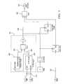
- FIG. 2is a detailed block diagram of an inverse tangent (ATAN) angle lookup function utilized by the system of FIG. 1 ;
- ATANinverse tangent
- FIG. 3is a block diagram of a rotation overflow detection function included in the inverse tangent (ATAN) angle lookup function of FIG. 2 ;
- the raw data generated by sensing elements within the sensoris independently processed by a separate control unit and then compared with the sensor's output message data processed internally within the sensor. So long as the sensor output message data is in agreement with the independently computed data (to a specified tolerance), the sensor is deemed to have correctly internally processed its own raw data, thereby satisfying the PEI of the sensor.
- PEIprogram execution integrity
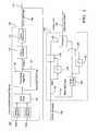
- the exemplary communication-based sensor 102is a steering angle sensor and includes a pair of sensing elements 104 a , 104 b that generate analog voltage inputs received and read by a processor 106 .
- the processor 106may include an analog to digital conversion (ADC) mechanism for providing raw, unprocessed digital data in the form of sine and cosine values. The raw sine and cosine values are then processed in accordance with an internal processing algorithm 108 of the sensor 102 .
- ADCanalog to digital conversion
- the output of processing algorithm 108represents the actual, absolute steering wheel angle information used by one or more vehicle control systems in communication with the vehicle communication bus. Accordingly, a communication controller 110 and associated transceiver 112 provide an appropriate hardware interface to the vehicle communication bus 114 . In a conventionally configured communication-based steering angle sensor, only the processed steering angle data is communicated externally from the sensor. However, as further shown in FIG. 1 , sensor 102 is modified so as to also redundantly provide the raw, unprocessed data 116 as part of its output communication message 118 .
- control unit 120receives the output communication message 118 from sensor 102 and separates the absolute steering wheel angle (SWA) data 122 from the raw data 116 .
- the raw data 116(sine and cosine signals) is inputted to an inverse tangent function block (ATAN) 124 that, in addition to implementing an arc tangent lookup function, provides overflow detection and rotation detection for providing an independently processed steering angle, described in further detail hereinafter.
- ATANinverse tangent function block
- FIG. 2is a more detailed block diagram of an ATAN angle lookup portion 200 of the ATAN function block 124 , particularly illustrating the sine and cosine inputs of the raw steering angle data 116 and an intermediate output (ATAN angle) 202 representing the sensor angle in degrees ( ⁇ 180°).
- the sine valueis scaled up by a factor of 128 (2 7 ) to preserve resolution in division.
- An ATAN lookup table 204provides a first quadrant angle value in order to conserve available memory, and the sign of the cosine and sine values are reapplied to provide the correct angle quadrant.
- the determined ATAN angle 202is further inputted to a rotation overflow detection portion 300 of the ATAN function block 124 , which produces an internal output 302 reflective of the direction of rotation of the steering angle.
- Angle changesare limited by Nyquist criteria to be less than ⁇ 180°. Any changes that are greater than 180° are considered overflows, which can either be in a clockwise direction or a counterclockwise direction. For a detected counterclockwise rotation, output 302 will have a value of 1, while for a detected clockwise rotation, output 302 will have a value of ⁇ 1. Otherwise, the value of output 302 will be 0.
- FIG. 4there is shown another block diagram illustrating a rotation angle determination portion 400 of ATAN block 124 , which utilizes the rotation/overflow output 302 of FIG. 3 (determined from ATAN angle 202 ) to generate a rotation angle output in degrees.
- a rotation counter 404is used to sum the positive and negative rotations determined by the rotation overflow detection function 300 , and this value is then multiplied by ⁇ 360 degrees.
- steering angle informationis provided from the communication-based steering angle sensor to a vehicle a communication bus is independently verified to determine whether the sensor or module sending the angle information processed the raw sensor data correctly.
- the verificationis determined by comparing the change in steering angle position, it is contemplated that the comparison may be carried out in other ways (e.g., by directly comparing current steering angles provided by the sensor and independently computed by control unit 120 ).
- the specific steering angle reconstruction (processing) from the raw sensor dataneed not necessarily carried out in the specific manner shown in the Figures, and could be implemented with the same or a different resolution than provided by the sensor's internal algorithm. Regardless of how the calculation is carried out, the present invention embodiments provide a redundant comparison of communication-based sensor information to ensure the information is compatible with robustly designed systems that use the information.
- the above described method embodimentsmay take the form of computer or controller implemented processes and apparatuses for practicing those processes.
- the disclosurecan also be embodied in the form of computer program code containing instructions embodied in tangible media, such as floppy diskettes, CD-ROMs, hard drives, or any other computer-readable storage medium, wherein, when the computer program code is loaded into and executed by a computer or controller, the computer becomes an apparatus for practicing the invention.
- the disclosuremay also be embodied in the form of computer program code or signal, for example, whether stored in a storage medium, loaded into and/or executed by a computer or controller, or transmitted over some transmission medium, such as over electrical wiring or cabling, through fiber optics, or via electromagnetic radiation, wherein, when the computer program code is loaded into and executed by a computer, the computer becomes an apparatus for practicing the invention.
- the computer program code segmentsconfigure the microprocessor to create specific logic circuits.
Landscapes
- Physics & Mathematics (AREA)
- General Physics & Mathematics (AREA)
- Arrangements For Transmission Of Measured Signals (AREA)
- Power Steering Mechanism (AREA)
- Measurement Of Length, Angles, Or The Like Using Electric Or Magnetic Means (AREA)
Abstract
Description
Claims (18)
Priority Applications (2)
| Application Number | Priority Date | Filing Date | Title |
|---|---|---|---|
| US10/910,954US7884715B2 (en) | 2004-08-04 | 2004-08-04 | Method and system for program execution integrity for communication-based angle sensor |
| EP05076587AEP1624290A3 (en) | 2004-08-04 | 2005-07-12 | Angle sensor |
Applications Claiming Priority (1)
| Application Number | Priority Date | Filing Date | Title |
|---|---|---|---|
| US10/910,954US7884715B2 (en) | 2004-08-04 | 2004-08-04 | Method and system for program execution integrity for communication-based angle sensor |
Publications (2)
| Publication Number | Publication Date |
|---|---|
| US20060061355A1 US20060061355A1 (en) | 2006-03-23 |
| US7884715B2true US7884715B2 (en) | 2011-02-08 |
Family
ID=35414654
Family Applications (1)
| Application Number | Title | Priority Date | Filing Date |
|---|---|---|---|
| US10/910,954Expired - Fee RelatedUS7884715B2 (en) | 2004-08-04 | 2004-08-04 | Method and system for program execution integrity for communication-based angle sensor |
Country Status (2)
| Country | Link |
|---|---|
| US (1) | US7884715B2 (en) |
| EP (1) | EP1624290A3 (en) |
Families Citing this family (5)
| Publication number | Priority date | Publication date | Assignee | Title |
|---|---|---|---|---|
| US7904278B2 (en)* | 2006-05-02 | 2011-03-08 | The Johns Hopkins University | Methods and system for program execution integrity measurement |
| DE102009053280A1 (en)* | 2009-11-13 | 2011-05-19 | Arnold & Richter Cine Technik Gmbh & Co. Betriebs Kg | Digital camera and method for monitoring a signal processing device |
| DE102011078586A1 (en)* | 2011-07-04 | 2013-01-10 | Robert Bosch Gmbh | Redundant determination of the rotational movement of an electric machine |
| JP6579377B2 (en)* | 2015-11-30 | 2019-09-25 | 株式会社ジェイテクト | Vehicle steering system |
| US11313702B2 (en)* | 2020-07-30 | 2022-04-26 | Microchip Technology Inc. | System and method for monitoring analog front-end (AFE) circuitry of an inductive position sensor |
Citations (18)
| Publication number | Priority date | Publication date | Assignee | Title |
|---|---|---|---|---|
| US4970638A (en)* | 1988-10-31 | 1990-11-13 | The United States Of America As Represented By The Secretary Of The Air Force | Control of unknown systems via deconvolution |
| US5072358A (en)* | 1990-03-09 | 1991-12-10 | Daytronic Corporation | Process controller |
| US5257210A (en)* | 1989-09-28 | 1993-10-26 | Endress U. Hauser Gmbh U. Co. | Processor for processing sensor signals to obtain a desired transfer behavior |
| US5750908A (en)* | 1996-02-26 | 1998-05-12 | Ade Corproation | Testing system with real time/off line functionality allocation |
| US5991840A (en)* | 1996-07-30 | 1999-11-23 | Oki Electric Industry Co., Ltd. | Computer expansion unit with circuitry for reliable communication on auxiliary bus |
| US20020050931A1 (en) | 2000-10-31 | 2002-05-02 | Lieberman Robert A. | Surveillance system and method |
| US20020056056A1 (en) | 1999-05-10 | 2002-05-09 | Ross Bannatyne | Electronic control apparatus with memory validation and method |
| US20030040878A1 (en) | 2001-08-09 | 2003-02-27 | Rovsing Dynamics A/S | Automatic machinery fault diagnostic method and apparatus |
| US20030102959A1 (en) | 1996-12-16 | 2003-06-05 | Wolfgang Bitzer | Process for securing the privacy of data transmission |
| US6588540B2 (en) | 2001-07-26 | 2003-07-08 | Delphi Technologies, Inc. | Steer-by-wire redundant handwheel control |
| US6650979B1 (en) | 1999-09-25 | 2003-11-18 | Volkswagen Ag | System for controlling motor vehicle components according to the “drive-by-wire” principle |
| US6648096B2 (en) | 2000-10-27 | 2003-11-18 | Siemens Aktiengesellschaft | Method and device for determining a steering angle of a motor vehicle |
| US20030216879A1 (en) | 2002-05-14 | 2003-11-20 | Analysis & Measurement Services Corporation | Integrated system for verifying the performance and health of instruments and processes |
| US20040046112A1 (en) | 2002-09-10 | 2004-03-11 | Trw Inc. | Steering wheel angle sensor |
| US20050007096A1 (en)* | 2003-06-18 | 2005-01-13 | Dimino Steven A. | System and method for proactive motor wellness diagnosis |
| US6952443B1 (en)* | 1998-08-31 | 2005-10-04 | Samsung Electronics Co., Ltd. | Method and apparatus for determining rate of data transmitted at variable rates |
| US7131046B2 (en)* | 2002-12-03 | 2006-10-31 | Verigy Ipco | System and method for testing circuitry using an externally generated signature |
| US7444020B2 (en)* | 2003-07-01 | 2008-10-28 | Thomson Licensing | Reduction of rounding errors during the processing of digital image data |
Family Cites Families (1)
| Publication number | Priority date | Publication date | Assignee | Title |
|---|---|---|---|---|
| US5495954A (en)* | 1994-05-16 | 1996-03-05 | Schmit; Joel A. | Modular storage unit kit |
- 2004
- 2004-08-04USUS10/910,954patent/US7884715B2/ennot_activeExpired - Fee Related
- 2005
- 2005-07-12EPEP05076587Apatent/EP1624290A3/ennot_activeWithdrawn
Patent Citations (18)
| Publication number | Priority date | Publication date | Assignee | Title |
|---|---|---|---|---|
| US4970638A (en)* | 1988-10-31 | 1990-11-13 | The United States Of America As Represented By The Secretary Of The Air Force | Control of unknown systems via deconvolution |
| US5257210A (en)* | 1989-09-28 | 1993-10-26 | Endress U. Hauser Gmbh U. Co. | Processor for processing sensor signals to obtain a desired transfer behavior |
| US5072358A (en)* | 1990-03-09 | 1991-12-10 | Daytronic Corporation | Process controller |
| US5750908A (en)* | 1996-02-26 | 1998-05-12 | Ade Corproation | Testing system with real time/off line functionality allocation |
| US5991840A (en)* | 1996-07-30 | 1999-11-23 | Oki Electric Industry Co., Ltd. | Computer expansion unit with circuitry for reliable communication on auxiliary bus |
| US20030102959A1 (en) | 1996-12-16 | 2003-06-05 | Wolfgang Bitzer | Process for securing the privacy of data transmission |
| US6952443B1 (en)* | 1998-08-31 | 2005-10-04 | Samsung Electronics Co., Ltd. | Method and apparatus for determining rate of data transmitted at variable rates |
| US20020056056A1 (en) | 1999-05-10 | 2002-05-09 | Ross Bannatyne | Electronic control apparatus with memory validation and method |
| US6650979B1 (en) | 1999-09-25 | 2003-11-18 | Volkswagen Ag | System for controlling motor vehicle components according to the “drive-by-wire” principle |
| US6648096B2 (en) | 2000-10-27 | 2003-11-18 | Siemens Aktiengesellschaft | Method and device for determining a steering angle of a motor vehicle |
| US20020050931A1 (en) | 2000-10-31 | 2002-05-02 | Lieberman Robert A. | Surveillance system and method |
| US6588540B2 (en) | 2001-07-26 | 2003-07-08 | Delphi Technologies, Inc. | Steer-by-wire redundant handwheel control |
| US20030040878A1 (en) | 2001-08-09 | 2003-02-27 | Rovsing Dynamics A/S | Automatic machinery fault diagnostic method and apparatus |
| US20030216879A1 (en) | 2002-05-14 | 2003-11-20 | Analysis & Measurement Services Corporation | Integrated system for verifying the performance and health of instruments and processes |
| US20040046112A1 (en) | 2002-09-10 | 2004-03-11 | Trw Inc. | Steering wheel angle sensor |
| US7131046B2 (en)* | 2002-12-03 | 2006-10-31 | Verigy Ipco | System and method for testing circuitry using an externally generated signature |
| US20050007096A1 (en)* | 2003-06-18 | 2005-01-13 | Dimino Steven A. | System and method for proactive motor wellness diagnosis |
| US7444020B2 (en)* | 2003-07-01 | 2008-10-28 | Thomson Licensing | Reduction of rounding errors during the processing of digital image data |
Also Published As
| Publication number | Publication date |
|---|---|
| US20060061355A1 (en) | 2006-03-23 |
| EP1624290A2 (en) | 2006-02-08 |
| EP1624290A3 (en) | 2007-05-02 |
Similar Documents
| Publication | Publication Date | Title |
|---|---|---|
| US10053142B2 (en) | Electric power steering apparatus | |
| US8326490B2 (en) | Steering angle sensor system and method for measuring a steering angle | |
| KR19990036222A (en) | Microprocessor Systems for Critical Safety Control Systems | |
| US12024149B2 (en) | Wheel speed sensor interface circuit, operation method thereof, and electronic control system | |
| US7376498B2 (en) | Vehicle controller | |
| JP5844178B2 (en) | In-vehicle device | |
| US7884715B2 (en) | Method and system for program execution integrity for communication-based angle sensor | |
| US8868298B2 (en) | Electric power assist steering motor sensor redundancy | |
| CN111051181A (en) | Steer-by-wire system and method for operating a steer-by-wire system | |
| US11994387B2 (en) | Inductive sensor with improved safety | |
| US6971047B2 (en) | Error handling of software modules | |
| CN108860312B (en) | Method for calibrating a steering angle sensing device of a motor vehicle | |
| Kohn et al. | Markov chain-based reliability analysis for automotive fail-operational systems | |
| CN116161110A (en) | Steering-by-wire system, redundancy backup method and device thereof, storage medium and vehicle | |
| KR20210058566A (en) | Electronic system, fault detecting method thereof, system on chip and bus system | |
| US10464597B2 (en) | Apparatus and method for monitoring a signal path, and signal processing system | |
| GB2391333A (en) | Method and apparatus for selecting between two sensor output signals in an electronic throttle system. | |
| JP2005114442A (en) | Resolver / digital converter with failure detection function | |
| KR20170065430A (en) | Apparatus for complex sensing | |
| US11231297B2 (en) | Providing availability of rotary position sensor information after hardware failures | |
| JP2011126327A (en) | On-vehicle controller | |
| KR20110051933A (en) | Sensor compensation device for steering recognition of vehicle | |
| JP5286916B2 (en) | Vehicle behavior sensor temperature correction device | |
| CN117985109B (en) | Steering wheel angle measurement method, controller, vehicle and readable storage medium | |
| US20210318873A1 (en) | Circuit for Verifying the Content of Registers |
Legal Events
| Date | Code | Title | Description |
|---|---|---|---|
| AS | Assignment | Owner name:DELPHI TECHNOLOGIES INC., MICHIGAN Free format text:ASSIGNMENT OF ASSIGNORS INTEREST;ASSIGNORS:WENDLING, SCOTT M.;SMITH, TERRENCE;KLASS, JEFFREY T.;AND OTHERS;REEL/FRAME:015221/0965;SIGNING DATES FROM 20040817 TO 20040818 Owner name:DELPHI TECHNOLOGIES INC., MICHIGAN Free format text:ASSIGNMENT OF ASSIGNORS INTEREST;ASSIGNORS:WENDLING, SCOTT M.;SMITH, TERRENCE;KLASS, JEFFREY T.;AND OTHERS;SIGNING DATES FROM 20040817 TO 20040818;REEL/FRAME:015221/0965 | |
| AS | Assignment | Owner name:GM GLOBAL TECHNOLOGY OPERATIONS, INC., MICHIGAN Free format text:ASSIGNMENT OF ASSIGNORS INTEREST;ASSIGNOR:DELPHI TECHNOLOGIES, INC.;REEL/FRAME:023449/0065 Effective date:20091002 Owner name:GM GLOBAL TECHNOLOGY OPERATIONS, INC.,MICHIGAN Free format text:ASSIGNMENT OF ASSIGNORS INTEREST;ASSIGNOR:DELPHI TECHNOLOGIES, INC.;REEL/FRAME:023449/0065 Effective date:20091002 | |
| AS | Assignment | Owner name:GM GLOBAL TECHNOLOGY OPERATIONS, INC.,MICHIGAN Free format text:ASSIGNMENT OF ASSIGNORS INTEREST;ASSIGNOR:DELPHI TECHNOLOGIES, INC.;REEL/FRAME:023988/0754 Effective date:20091002 Owner name:UNITED STATES DEPARTMENT OF THE TREASURY,DISTRICT Free format text:SECURITY AGREEMENT;ASSIGNOR:GM GLOBAL TECHNOLOGY OPERATIONS, INC.;REEL/FRAME:023990/0349 Effective date:20090710 Owner name:UAW RETIREE MEDICAL BENEFITS TRUST,MICHIGAN Free format text:SECURITY AGREEMENT;ASSIGNOR:GM GLOBAL TECHNOLOGY OPERATIONS, INC.;REEL/FRAME:023990/0831 Effective date:20090710 Owner name:GM GLOBAL TECHNOLOGY OPERATIONS, INC., MICHIGAN Free format text:ASSIGNMENT OF ASSIGNORS INTEREST;ASSIGNOR:DELPHI TECHNOLOGIES, INC.;REEL/FRAME:023988/0754 Effective date:20091002 Owner name:UNITED STATES DEPARTMENT OF THE TREASURY, DISTRICT Free format text:SECURITY AGREEMENT;ASSIGNOR:GM GLOBAL TECHNOLOGY OPERATIONS, INC.;REEL/FRAME:023990/0349 Effective date:20090710 Owner name:UAW RETIREE MEDICAL BENEFITS TRUST, MICHIGAN Free format text:SECURITY AGREEMENT;ASSIGNOR:GM GLOBAL TECHNOLOGY OPERATIONS, INC.;REEL/FRAME:023990/0831 Effective date:20090710 | |
| AS | Assignment | Owner name:GM GLOBAL TECHNOLOGY OPERATIONS, INC., MICHIGAN Free format text:RELEASE BY SECURED PARTY;ASSIGNOR:UNITED STATES DEPARTMENT OF THE TREASURY;REEL/FRAME:025386/0591 Effective date:20100420 Owner name:GM GLOBAL TECHNOLOGY OPERATIONS, INC., MICHIGAN Free format text:RELEASE BY SECURED PARTY;ASSIGNOR:UAW RETIREE MEDICAL BENEFITS TRUST;REEL/FRAME:025386/0503 Effective date:20101026 | |
| AS | Assignment | Owner name:PACIFIC CENTURY MOTORS, INC., CHINA Free format text:ASSIGNMENT OF ASSIGNORS INTEREST;ASSIGNOR:GM GLOBAL TECHNOLOGY OPERATIONS, INC.;REEL/FRAME:027842/0918 Effective date:20101130 Owner name:GM GLOBAL TECHNOLOGY OPERATIONS, INC., MICHIGAN Free format text:ASSIGNMENT OF ASSIGNORS INTEREST;ASSIGNOR:GM GLOBAL TECHNOLOGY OPERATIONS, INC.;REEL/FRAME:027842/0918 Effective date:20101130 | |
| AS | Assignment | Owner name:STEERING SOLUTIONS IP HOLDING CORPORATION, MICHIGA Free format text:ASSIGNMENT OF ASSIGNORS INTEREST;ASSIGNORS:PACIFIC CENTURY MOTORS, INC.;NEXTEER (BEIJING) TECHNOLOGY CO., LTD.;REEL/FRAME:027870/0666 Effective date:20120126 | |
| AS | Assignment | Owner name:INTEL CORPORATION, CALIFORNIA Free format text:ASSIGNMENT OF ASSIGNORS INTEREST;ASSIGNOR:QLOGIC CORPORATION;REEL/FRAME:028168/0202 Effective date:20120229 | |
| REMI | Maintenance fee reminder mailed | ||
| LAPS | Lapse for failure to pay maintenance fees | ||
| STCH | Information on status: patent discontinuation | Free format text:PATENT EXPIRED DUE TO NONPAYMENT OF MAINTENANCE FEES UNDER 37 CFR 1.362 | |
| FP | Lapsed due to failure to pay maintenance fee | Effective date:20150208 |