US7883531B2 - Multi-axial bone plate system - Google Patents
Multi-axial bone plate systemDownload PDFInfo
- Publication number
- US7883531B2 US7883531B2US11/175,426US17542605AUS7883531B2US 7883531 B2US7883531 B2US 7883531B2US 17542605 AUS17542605 AUS 17542605AUS 7883531 B2US7883531 B2US 7883531B2
- Authority
- US
- United States
- Prior art keywords
- bone plate
- bone
- fixation member
- compression member
- orthopedic
- Prior art date
- Legal status (The legal status is an assumption and is not a legal conclusion. Google has not performed a legal analysis and makes no representation as to the accuracy of the status listed.)
- Expired - Fee Related, expires
Links
Images


Classifications
- A—HUMAN NECESSITIES
- A61—MEDICAL OR VETERINARY SCIENCE; HYGIENE
- A61B—DIAGNOSIS; SURGERY; IDENTIFICATION
- A61B17/00—Surgical instruments, devices or methods
- A61B17/56—Surgical instruments or methods for treatment of bones or joints; Devices specially adapted therefor
- A61B17/58—Surgical instruments or methods for treatment of bones or joints; Devices specially adapted therefor for osteosynthesis, e.g. bone plates, screws or setting implements
- A61B17/68—Internal fixation devices, including fasteners and spinal fixators, even if a part thereof projects from the skin
- A61B17/70—Spinal positioners or stabilisers, e.g. stabilisers comprising fluid filler in an implant
- A61B17/7059—Cortical plates
- A—HUMAN NECESSITIES
- A61—MEDICAL OR VETERINARY SCIENCE; HYGIENE
- A61B—DIAGNOSIS; SURGERY; IDENTIFICATION
- A61B17/00—Surgical instruments, devices or methods
- A61B17/56—Surgical instruments or methods for treatment of bones or joints; Devices specially adapted therefor
- A61B17/58—Surgical instruments or methods for treatment of bones or joints; Devices specially adapted therefor for osteosynthesis, e.g. bone plates, screws or setting implements
- A61B17/68—Internal fixation devices, including fasteners and spinal fixators, even if a part thereof projects from the skin
- A61B17/80—Cortical plates, i.e. bone plates; Instruments for holding or positioning cortical plates, or for compressing bones attached to cortical plates
- A61B17/8033—Cortical plates, i.e. bone plates; Instruments for holding or positioning cortical plates, or for compressing bones attached to cortical plates having indirect contact with screw heads, or having contact with screw heads maintained with the aid of additional components, e.g. nuts, wedges or head covers
- A61B17/8047—Cortical plates, i.e. bone plates; Instruments for holding or positioning cortical plates, or for compressing bones attached to cortical plates having indirect contact with screw heads, or having contact with screw heads maintained with the aid of additional components, e.g. nuts, wedges or head covers wherein the additional element surrounds the screw head in the plate hole
- A—HUMAN NECESSITIES
- A61—MEDICAL OR VETERINARY SCIENCE; HYGIENE
- A61B—DIAGNOSIS; SURGERY; IDENTIFICATION
- A61B17/00—Surgical instruments, devices or methods
- A61B17/56—Surgical instruments or methods for treatment of bones or joints; Devices specially adapted therefor
- A61B17/58—Surgical instruments or methods for treatment of bones or joints; Devices specially adapted therefor for osteosynthesis, e.g. bone plates, screws or setting implements
- A61B17/68—Internal fixation devices, including fasteners and spinal fixators, even if a part thereof projects from the skin
- A61B17/84—Fasteners therefor or fasteners being internal fixation devices
- A61B17/846—Nails or pins, i.e. anchors without movable parts, holding by friction only, with or without structured surface
- A61B17/848—Kirschner wires, i.e. thin, long nails
Definitions
- the present inventionrelates generally to an orthopedic implant assembly system and in particular to a multi-axial bone plate system.
- Orthopedic implant assembly systems having a multi-axial bone plateinclude at least two pedicular screws anchored in adjacent vertebrae to be treated and a connecting plate designed to connect the screw heads together in a rigid manner.
- Previous referencesdisclose a system of this kind in which each pedicular screw has a hexagonal section part for inserting the screw into the bone and on top of which is a threaded shank.
- the platehas a plurality of oblong openings through which the various threaded shanks can be inserted and an open groove on its bottom face to prevent rotation of the hexagonal part of each pedicular screw.
- Each pedicular screwis associated with a stirrup through which the threaded shank of the screw also passes and which straddles the top of the plate. Finally, a nut is screwed onto the threaded shank to trap and immobilize the plate with the stirrup on top of it, between it and the hexagonal portion of the screw.
- known systemsinclude at least two pedicular screws and a connecting plate for linking screws together in essentially a rigid manner.
- Each screwhas a bone anchor threaded part, a non-circular section head, and a threaded end shank adapted to cooperate with a nut.
- the platehas at least one opening adapted to have the threaded end shank of the screw pass through it and be trapped between the screw head and the nut.
- Raised patternsare provided on the top face of the plate and on the bottom face of the stirrup to prevent longitudinal sliding of the plate relative to the screw.
- a locking memberis also provided for preventing relative angular movement between the heads of the screws and the connecting plate.
- the locking memberis adapted to be inserted between the plate and the screw head and includes a bar through which the threaded end shank of the screw passes.
- the locking memberfurther includes a first locking cooperation of shapes with the screw head and a second cooperation of shapes with the plate.
- the raised patternscan impede fine adjustment of the system. For example, there are only a particular number of discrete mutual positions of the plate and the stirrup, i.e., a particular number of discrete distances between the screws. Moreover, if the nut is overtightened before the final tightening, lateral sliding of the plate and the stirrup during adjustment may be impeded.
- drawbacks associated with other designsinclude that the first locking cooperation and second cooperation of shapes with the plate forbid and restrict plate movement in an anterior and posterior direction once the pedicle screw has been rested against the plate member.
- most plate systemsinclude a bone fastener with a threaded end extended from the vertebral body.
- a nutIn order to lock the screw relative to the plate, a nut must be used in combination with the screw.
- the problem associated with this designis that if the screw is not placed at the correct depth within the vertebral body, the assembly must be disassembled in order to either increase or decrease the depth of the screw in the vertebrae.
- An additional problemresults from this action due to the fact that once the screw has been placed too deep within the vertebral body, the screw might be less securely locked within the vertebral body when the screw is backed out and placed in its correct position.
- an orthopedic bone plating systemincludes a bone plate for placement adjacent one or more vertebral bodies.
- the bone platehas an aperture extending along a longitudinal axis of the bone plate.
- the assemblyfurther includes a locking element having a compression member and a fixation member wherein the compression member has an aperture and at least one deformable portion.
- the assemblyis connected to a vertebral body with the help of a bone fastener having a longitudinal axis.
- the bone fastenerfurther includes a stem and a bone-engaging portion.
- the stem of the bone fastenermay be slidably received within the aperture of the compression member.
- the compression membermay be brought into proximity of a vertebral body along the longitudinal axis of the bone fastener and create an increasing force which is exerted against the fixation member.
- a resulting forcecauses the fixation member to exert a pressure against the bone plate and translate a second resultant force back through the fixation member to the compression member causing the deformable portion of the compression member to clamp onto the bone fastener thereby locking the assembly together.
- the compression member and fixation membermay be separate elements wherein the fixation member includes an aperture for receiving the compression member. Furthermore, the compression member and fixation member may have mateable threads which are screwed together as the compression member is brought into proximately of the vertebral body.
- the fixation membermay further include a tapered aperture extending therethrough. Additionally, the bone fastener may be smooth.
- the orthopedic bone plate systemmay include a channel for receiving the fixation member, which permits the fixation member to slide relative to the bone plate.
- the channelbeing located within the bone plate.
- the fixation membermay include at least one key and the bone plate may include at least one keyway wherein the key may be received by the keyway.
- the keywaymay have a height that is greater than the height of the key in order to permit an angled orientation of the fixation member relative to the bone plate.
- an orthopedic bone plate implant systemhaving a plate member which may be placed adjacent and along one or more of the vertebral bodies.
- the plate memberincludes an aperture extending therethrough.
- the assemblyalso includes a split sleeve having a central aperture and a slot extending from an exterior surface of the split sleeve to the aperture. The slot permits the expansion and contraction of the aperture of the split sleeve.
- the split sleeveis sized to be received within the aperture of the plate member.
- the channel portionmay extend substantially the entire longitudinal direction of the plate and either come to a tapered end or abrupt end. Furthermore, the channel portion itself may also include a guide rail that receives a lateral pin extending from an exterior of the split sleeve. The lateral pin is placed and dimensioned on the split sleeve to be received by the guide rail when the split sleeve is placed in the channel portion of the plate member.
- the split sleevemay have two parallel flat walls and two opposite curved walls.
- the parallel flat wallsmay include the lateral pins of the split sleeve.
- the bone fastenermay have an end portion that is either smooth, concaved inwards or outwards relative to the vertebral body.
- the bone fastenermay further include a recess for cooperating with the tool.
- the recessmay be in the form of a hexagon, a slot or various other recesses and projections which can be made into a tool.
- a bottom portion of the expansible screwmay include at least one slit extending vertically to allow the compression or expansion of a portion of the expansible screw.
- the expansible screwmay include a ridge which overhangs at least partly the split sleeve.
- the ridgemay further be defined in that it has at least two flat surfaces on its sidewall.
- the split sleevemay include a threaded portion and the expansible screw may include a second threaded portion wherein the two threaded portions are able to be screwed to one another.
- the plate member of the orthopedic inputmay include slots or ridges.
- the split sleevemay have a central aperture which has an interior with a greater circumference at the top of the interior as you get to the bottom of the interior.
- the expansible screw having an aperture withinmay include an exterior with a bottom portion angled so as to increase in size.
- the method of operation of the present inventionmay include the steps of providing a plate member, a bone fastener and a locking element as described herein.
- the bone fastenermay first be engaged to a vertebral body and then the stem of the bone fastener slidably receiving the plate member and the locking element about its circumference so that the stem is located within the apertures of the plate and the locking element respectively.
- the locking elementmay include a compression member and a fixation member.
- the compression memberAs the compression member is brought into proximity of the vertebral body along the longitudinal axis of the bone fastener, the compression member causes an increasing force to be exerted against the fixation member which in response places pressure against the plate member until a resultant force is translated back through the two members and causes the deformable portion of the compression member to clamp the bone fastener relative to the bone plate.
- the method of fixing one or more vertebral bodies in a desired relationshipmay further include adjusting the position of the bone fastener after sliding the plate member over the stem of the bone fastener.
- a bone fasteneris also included for connecting the plate member to a vertebral body.
- the fastenermay include a first end portion engageable with the vertebral body and a second end portion capable of extending through the aperture of the split sleeve.
- a final component of the assemblyis an expansible screw having an opening extending therethrough.
- the openingis sized to receive the second end portion of the fastener and further includes a top portion and a bottom portion.
- the bottom portion of the screwis capable of expanding and contracting about a central axis of the screw.
- FIG. 1is a schematic drawing illustrating an embodiment of the orthopedic implant of the present invention implanted in a vertebrae
- FIG. 2is an exploded perspective view of one embodiment of the system of the present invention
- FIG. 3is a sectional view of the embodiment illustrated in FIG. 2 partly assembled and taken along line 3 - 3 in FIG. 2 and viewed in direction of the arrows;
- FIG. 4 ais a perspective view of an elongate plate used in one embodiment of the present invention.
- FIG. 4 bis a cross-sectional view of a plate used in one embodiment of the present invention.
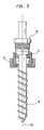
- FIG. 5is a front perspective view of a bone fastener used in one embodiment of the present invention.
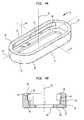
- FIG. 6 ais a perspective view of a split sleeve used in one embodiment of the present invention.
- FIG. 6 bis a cross-sectional view of the split sleeve of FIG. 6 a;
- FIG. 7 ais a perspective view of an expandable screw used in one embodiment of the present invention.
- FIG. 7 bis a cross-sectional view of the expandable screw of FIG. 7 a;
- the spinal implant system 10 of the present inventionincludes a plate 12 , an expansible locking screw 16 and a bone fastener 18 .
- bone fasteners 18function to anchor plate 12 to vertebral bodies 2 and may be orientated at an angle with regard to the vertebral body.
- FIG. 2details the assembly of the parts of FIG. 1 employed in the spinal implant system 10 .
- the spinal implant system 10includes an elongate member such as plate 12 , expansible screw 16 , bone fastener 18 and split sleeve 14 .
- elongate membersuch as plate 12 , expansible screw 16 , bone fastener 18 and split sleeve 14 .
- plate 12expansible screw 16
- bone fastener 18and split sleeve 14
- a plurality of plates 12can be used in conjunction with each other, or a greater or lesser number of bone fasteners 18 may be used depending upon the configuration of the elongate member, the medical problem to be addressed and/or any other factors.
- the present inventioncontemplates having at least the same amount of split sleeves 14 , expansible screws 16 and bone fasteners 18 . Furthermore, the present invention contemplates each plate 12 will be used with at least a single bone screw 18 and related devices; however, each plate 12 is capable of receiving a plurality of split sleeves 14 , expansible screws 16 and bone fasteners 18 without deviating from the scope of the present invention.
- Plate 12preferably has a generally rounded-rectangular or oval shape, an upper surface 30 , a lower surface 32 , a proximal end 31 and a distal end 33 . Additionally, plate 12 has two opposing sides, right rail 13 and left rail 15 . Right rail 13 and left rail 15 may be substantially mirror images of one another. Plate 12 further includes elongate aperture 36 extending along the longitudinal axis 34 of plate 12 from upper surface 30 to lower surface 32 and from end 31 to end 33 .
- Elongate aperture 36has a generally open geometry enabling split sleeve 14 , expansible screw 16 and bone fastener 18 to be placed at any number of axial positions within elongate aperture 36 .
- Elongate aperture 36generally has a non-uniform geometry about a central axis 35 which extends perpendicularly to the plane of plate 12 .
- right rail 13 and left rail 15surround elongate aperture 36 of plate 12 and include an upper wall 38 adjacent to upper surface 30 .
- the geometry of left rail 13 and upper rail 15 of aperture 36further include a key way or groove 40 adjacent to upper wall 38 composed of median ceiling 42 , median portion 44 and median ridge 46 .
- a lower portion 48 of rails 13 and 15 , adjacent to key way 40includes a lower surface 50 adjacent to lower wall 49 and sidewall 52 adjacent to lower ridge 50 , concludes the remaining exterior geometry of elongate aperture 36 .
- elongate aperture 36has substantially the same geometry extending from the proximal end 31 to the distal end 33 or the previously mentioned ridge portions and rails may either abruptly halt or in a preferred embodiment may linearly transition into a smooth geometry at the distal and proximal ends as shown in FIG. 4 a.
- Plate 12is of sufficient length to bridge more than one vertebrae, as shown in FIG. 1 , for which stabilization is required, and it will be appreciated, various dimensions of the plate and its features exist, all within the scope of the present invention.
- the plate 12may be substantially planar as shown in FIG. 2 or have a concave shape as shown in FIG. 1 .
- the plate 12is preferably made from a biologically inert material, for example, any metal customarily used for surgical devices and particularly those used for bone screws and pins, such as titanium or stainless steel.
- a biologically inert materialfor example, any metal customarily used for surgical devices and particularly those used for bone screws and pins, such as titanium or stainless steel.
- suitable materialsinclude, but are not limited to, alloys, composite materials, ceramics or carbon fiber materials.
- Bone fastener 18is in the shape of a pedicle screw; however, various other fasteners may be utilized including bone hooks.
- bone fastener 18has a threaded end 152 for anchoring the fastener into a vertebra or similar bone structure and an opposing stem end 150 .
- stem end 150is smooth.
- Bone fastener 18may further include recess 154 to enable bone fastener 18 to be screwed into a vertebrae using a screw driver, wrench, allen key or similar tool.
- Recess 154may be in the form of a hexagon as shown in the figures or alternatively, may be a slot or other shapes which allow the tools previously mentioned to mate to the bone fastener 18 and screw the bone fastener 18 into a vertebral body.
- Smooth stem 150is preferably sized to be able to be slidably received by expansible screw 16 , detailed in FIGS. 7 a and 7 b , specifically aperture 124 of expansible screw 16 as will be described below.
- Bone fastener 18may also include upper end section 156 , which may have a substantially flat end surface area as shown in FIG. 5 . However, in an alternate embodiment, upper section 156 may also have a spherical configuration either concave or convex relative to threaded end 152 .
- Split sleeve 14may have a generally rounded-square or oval shape.
- Split sleeve 14may include a first flat side 60 , and opposing second flat side 62 , a first arcuate side 64 and an opposing second arcuate side 66 .
- Sides 64 and 66could be of any shape, however, sides 60 , 62 preferably permit split sleeve 14 to slide within aperture 36 without rotating.
- Split sleeve 14may further include an upper surface 68 and a lower surface 70 along with aperture 72 , extending therebetween.
- Aperture 72generally has a non-uniform geometry about central axis 74 .
- the first side 60 and second side 62may include keys 76 and 78 which engage key ways 40 on rails 13 and 15 of the plate 12 , respectively.
- key 78may be substantially similar to key 76 having all the same features.
- Key 76protrudes from second side 62 and includes top ledge 80 and lower ledge 82 extending horizontally from second side 62 .
- Side 84 adjacent to both top ledge 80 and lower ledge 82extends between the two ledges.
- Key 76may be sized and located on second side 62 so when split sleeve 14 is placed into elongate aperture 36 of plate 12 , pin 76 is housed within key way 40 as defined by side 84 .
- Keys 76 and 78may have a height slightly less than the height of key way 40 to permit split sleeve 14 to slide freely along key way 40 of plate 12 .
- the reduced height of key 76enables split sleeve 14 to have an angled orientation relative to plate 12 , in the sagittal plane.
- keys 76 , 78extend only part way along sides 60 , 62 but could extend the entire length.
- Split sleeve 14further includes through-slot 102 vertically extending from upper surface 68 to lower surface 70 .
- Slot 102is further defined in that it extends horizontally from the exterior of split sleeve 14 to aperture 72 .
- the outer circumference of split sleeve 14is substantially continuous except for through-slot 102 .
- Through-slot 102permits split sleeve 14 to expand and compress horizontally thereby increasing or decreasing the diameter of aperture 72 .
- Split sleeve 14may be compressed about slot 102 to allow insertions of keys 76 , 78 into key way 40 .
- aperture 72has a non-uniform geometry extending between upper surface 68 to lower surface 70 of split sleeve 14 .
- inner wall 90is adjacent to upper surface 68 .
- Inner wall 90may have a tapered design as shown in FIG. 6B to better receive expansible screw 16 , as will be described below.
- a first ridge 92extends from inner wall 90 towards central axis 74 , with median wall 94 extending downward towards lower surface 70 adjacent to first ridge 92 .
- a second ridge 96is adjacent to median wall 94 and extends toward central axis 74 while lower wall 98 is adjacent to second ridge 96 .
- Inner wall 90includes threads 91 which may be mated to the threads of the expansible screw 16 described herein after.
- Lower wall 98may include vertical wall 97 and tapered skirt 99 along with edge 101 .
- Inner wall 90 , first ridge 92 , median wall 94 , second ridge 96 and lower wall 98all combine to define female cone
- Split sleeve 14is placed within elongate aperture 36 of plate 12 when assembling the spinal implant assembly 10 . In this position, lower surface 70 of split sleeve 14 is rested on or slightly above lower ridge 50 of plate 12 and as previously mentioned, pins 76 and 78 are located within key way 40 at the right rail 13 and the left rail 15 of the plate 12 .
- Split sleeve 14is sized to move freely along plate 12 and permit a possible angled orientation of the split sleeve with respect to plate 12 in the sagittal plane.
- the height of split sleeve 14is less than the distance from the upper surface 30 , to lower ridge 50 .
- split sleeve 14has a width less than the distance between opposing rails 13 and 15 of aperture 36 of plate 12 .
- the expansible screw 16includes upper surface 120 , lower surface 122 and aperture 124 extending therebetween upper surface 120 and lower surface 122 .
- Expansible screw 16further includes cap section 126 and deflectable male cone section 128 .
- Axially extending portion 130includes threads 131 which are engageable with threads 91 on split sleeve 14 .
- Male cone section 128further includes, extending downward from ridge 132 , individual fingers 134 with slits 136 therebetween each individual finger 134 .
- fingers 134are tapered inwards so as to be slidably received by lower wall 90 of split sleeve 14 .
- Male cone 128 of expansible screw 16is designed so as to be able to receive fastener 18 and is geometrically constant throughout aperture 124 . However, as a force is exerted horizontally relative to central axis 138 of expansible screw 16 , male cone 128 is capable of compressing either inwardly or expanding outwardly in the same direction of the force applied.
- Cap section 126 of expansible screw 16includes not only upper surface 120 but also grip surface 140 and overhang 142 and may also include opposing slots 139 for cooperating with a tool.
- aperture 124also extends through cap section 126 thereby creating a continuous aperture through expansible screw 16 .
- plate 12 along with split sleeve 14is placed over smooth stem 150 of bone fastener 18 .
- First split sleeve 14may be placed within aperture 36 of plate 12 .
- first split sleeve 14 and plate 12are slidably received by stem 150 .
- bone fastener 18is a substantially cylindrical body having a center axis
- this alignmentmay be accomplished by aligning central axis 74 of split sleeve 14 to the center axis 158 of bone fastener 18 .
- Bone plate 12 and split sleeve 14are then freely moveable in a vertical direction relative to bone fastener 18 and specifically an anterior-posterior direction.
- expansible screw 16In order to lock the various components of the spinal implant assembly 10 together, expansible screw 16 must be screwed into split sleeve 14 . This is accomplished by first aligning aperture 124 of expansible screw 16 with upper section 156 of bone fastener 18 . Once again, since stem 150 of bone fastener 18 is substantially cylindrical and has a radial central axis 158 , central axis 138 of expansible screw 16 may be aligned with the radial central axis 158 of the bone fastener 18 .
- Aperture 72 of split sleeve 14is sized so as to be able to accept expansible screw 16 and bone fastener 18 at opposing ends. Furthermore, expansible screw 16 engages threads 91 within aperture 72 of split sleeve 14 and the two are screwed together such that the tapered portions of each engage one another. This causes an outward horizontal force against split sleeve 14 and an inward force on deflectable fingers 134 . The fingers 134 grip the stem 156 of the bone fastener 18 as they are constricted inwards. This is due to the fact that male cone 128 of expansible screw 16 is wedged shaped, i.e., having a narrower lower portion as compared to its upper portion.
- Through-slot 102 of split sleeve 14permits the expansion of split sleeve 14 in the horizontal direction.
- first side 60begins to apply pressure against upper wall 38 and lower wall 49 of the plate 12 .
- Key 78may contact median portion 44 of key way 40 located on plate 12 .
- second side 62also applies pressure against upper wall 38 and lower wall 49 as well as the fact that key 76 may contact median portion 44 of guide rail 40 of plate 12 .
- split sleeve 14expands horizontally increasing the size of through-slot 102 until the rails 13 and 15 of elongated aperture 36 of plate 12 apply a reactive force against the walls of split sleeve 14 thus locking the split sleeve in place.
- cap 126 of expansible screw 16In a locked position, cap 126 of expansible screw 16 , specifically overhang 142 of expansible screw 16 may abut upper surface 68 of split sleeve 14 . Thus, male cone 128 is completely housed in aperture 72 of split sleeve 14 .
- the rotation of expansible screw 16thus causes the plate to lock relative to the bone fastener 18 .
- the stem 150 of bone fastener 18may have a smooth surface to allow easy adjustment after plate 12 has been positioned and assembled, thus overcoming the disadvantage of threaded end fasteners.
- the surgeonmay easily change the bone screw position engaged with the vertebrae by loosening expansible screw 16 and sliding the assembly in either an anterior/posterior direction or inferior/superior direction. Afterwards, the assembly may be locked again by tightening expansible screw 16 . This avoids the problem of having to disassemble all the elements from one another in order to adjust only certain elements.
- FIG. 1may depict single elongated aperture 36 being divided into a plurality of apertures by cross-members extending between opposing rails 13 and 15 of plate 12 substantially perpendicular to longitudinal axis 34 .
- the cross-memberswould have to be sufficiently separated from one another as well as from proximal end 31 and distal end 33 to permit split sleeve 14 , expansible screw 16 and bone fastener 18 to be placed within the shortened apertures and still be locked together relative to plate 12 .
Landscapes
- Health & Medical Sciences (AREA)
- Orthopedic Medicine & Surgery (AREA)
- Life Sciences & Earth Sciences (AREA)
- Surgery (AREA)
- Neurology (AREA)
- Heart & Thoracic Surgery (AREA)
- Engineering & Computer Science (AREA)
- Biomedical Technology (AREA)
- Nuclear Medicine, Radiotherapy & Molecular Imaging (AREA)
- Medical Informatics (AREA)
- Molecular Biology (AREA)
- Animal Behavior & Ethology (AREA)
- General Health & Medical Sciences (AREA)
- Public Health (AREA)
- Veterinary Medicine (AREA)
- Prostheses (AREA)
- Surgical Instruments (AREA)
Abstract
Description
Claims (21)
Priority Applications (5)
| Application Number | Priority Date | Filing Date | Title |
|---|---|---|---|
| US11/175,426US7883531B2 (en) | 2005-07-06 | 2005-07-06 | Multi-axial bone plate system |
| PCT/IB2006/003319WO2007036807A2 (en) | 2005-07-06 | 2006-07-06 | Multi-axial bone plate system |
| EP06831584.5AEP1909669B1 (en) | 2005-07-06 | 2006-07-06 | Multi-axial bone plate system |
| US12/961,682US8486117B2 (en) | 2005-07-06 | 2010-12-07 | Multi-axial bone plate system |
| US13/926,238US8840649B2 (en) | 2005-07-06 | 2013-06-25 | Multi-axial bone plate system |
Applications Claiming Priority (1)
| Application Number | Priority Date | Filing Date | Title |
|---|---|---|---|
| US11/175,426US7883531B2 (en) | 2005-07-06 | 2005-07-06 | Multi-axial bone plate system |
Related Child Applications (1)
| Application Number | Title | Priority Date | Filing Date |
|---|---|---|---|
| US12/961,682DivisionUS8486117B2 (en) | 2005-07-06 | 2010-12-07 | Multi-axial bone plate system |
Publications (2)
| Publication Number | Publication Date |
|---|---|
| US20070010817A1 US20070010817A1 (en) | 2007-01-11 |
| US7883531B2true US7883531B2 (en) | 2011-02-08 |
Family
ID=37619185
Family Applications (3)
| Application Number | Title | Priority Date | Filing Date |
|---|---|---|---|
| US11/175,426Expired - Fee RelatedUS7883531B2 (en) | 2005-07-06 | 2005-07-06 | Multi-axial bone plate system |
| US12/961,682Expired - Fee RelatedUS8486117B2 (en) | 2005-07-06 | 2010-12-07 | Multi-axial bone plate system |
| US13/926,238Expired - LifetimeUS8840649B2 (en) | 2005-07-06 | 2013-06-25 | Multi-axial bone plate system |
Family Applications After (2)
| Application Number | Title | Priority Date | Filing Date |
|---|---|---|---|
| US12/961,682Expired - Fee RelatedUS8486117B2 (en) | 2005-07-06 | 2010-12-07 | Multi-axial bone plate system |
| US13/926,238Expired - LifetimeUS8840649B2 (en) | 2005-07-06 | 2013-06-25 | Multi-axial bone plate system |
Country Status (3)
| Country | Link |
|---|---|
| US (3) | US7883531B2 (en) |
| EP (1) | EP1909669B1 (en) |
| WO (1) | WO2007036807A2 (en) |
Cited By (25)
| Publication number | Priority date | Publication date | Assignee | Title |
|---|---|---|---|---|
| US20080065075A1 (en)* | 2004-08-17 | 2008-03-13 | Zimmer Spine, Inc. | METHOD FOR SPINE STABILIZATION DURING OSTEOSYNTHESIS (As Amended) |
| US20080172092A1 (en)* | 2007-01-12 | 2008-07-17 | Paul Edward Kraemer | System and method for spinal instrumentation |
| US20080287994A1 (en)* | 2007-04-19 | 2008-11-20 | Mi4Spine, Llc | Pedicle Screw and Rod System |
| US20090287261A1 (en)* | 2004-11-10 | 2009-11-19 | Jackson Roger P | Polyaxial bone screw with discontinuous helically wound capture connection |
| US20110118794A1 (en)* | 2006-06-26 | 2011-05-19 | Mi4Spine, Llc | Self distracting pedicle screw distraction device |
| US20120165873A1 (en)* | 2007-04-19 | 2012-06-28 | Mi4Spine, Llc | Minimally invasive percutaneous pedicle screw and slotted rod assembly |
| US8679116B2 (en)* | 2012-03-22 | 2014-03-25 | National Yang-Ming University | Multiple axes external bone fixing member |
| US20140135930A1 (en)* | 2012-11-09 | 2014-05-15 | Bacem Georges | Interbody Device With Opening to Allow Packing Graft and Other Biologies |
| US8992579B1 (en) | 2011-03-08 | 2015-03-31 | Nuvasive, Inc. | Lateral fixation constructs and related methods |
| US9060815B1 (en) | 2012-03-08 | 2015-06-23 | Nuvasive, Inc. | Systems and methods for performing spine surgery |
| US9468479B2 (en) | 2013-09-06 | 2016-10-18 | Cardinal Health 247, Inc. | Bone plate |
| US9517089B1 (en) | 2013-10-08 | 2016-12-13 | Nuvasive, Inc. | Bone anchor with offset rod connector |
| US9526620B2 (en) | 2009-03-30 | 2016-12-27 | DePuy Synthes Products, Inc. | Zero profile spinal fusion cage |
| US9662225B2 (en) | 2012-03-06 | 2017-05-30 | DePuy Synthes Products, Inc. | Nubbed plate |
| US9687354B2 (en) | 2008-03-26 | 2017-06-27 | DePuy Synthes Products, Inc. | Posterior intervertebral disc inserter and expansion techniques |
| US9788863B2 (en) | 2012-10-22 | 2017-10-17 | Globus Medical, Inc. | Posterior lumbar plate |
| US10159582B2 (en) | 2011-09-16 | 2018-12-25 | DePuy Synthes Products, Inc. | Removable, bone-securing cover plate for intervertebral fusion cage |
| US20190000520A1 (en)* | 2014-12-09 | 2019-01-03 | Arthrex, Inc. | Fracture fixation system including locking cap and wire |
| US10206787B2 (en) | 2006-12-22 | 2019-02-19 | Medos International Sarl | Composite vertebral spacers and instrument |
| US10335289B2 (en) | 2010-09-23 | 2019-07-02 | DePuy Synthes Products, Inc. | Stand alone intervertebral fusion device |
| US10369015B2 (en) | 2010-09-23 | 2019-08-06 | DePuy Synthes Products, Inc. | Implant inserter having a laterally-extending dovetail engagement feature |
| US10500062B2 (en) | 2009-12-10 | 2019-12-10 | DePuy Synthes Products, Inc. | Bellows-like expandable interbody fusion cage |
| US10940016B2 (en) | 2017-07-05 | 2021-03-09 | Medos International Sarl | Expandable intervertebral fusion cage |
| US11039865B2 (en) | 2018-03-02 | 2021-06-22 | Stryker European Operations Limited | Bone plates and associated screws |
| US11529241B2 (en) | 2010-09-23 | 2022-12-20 | DePuy Synthes Products, Inc. | Fusion cage with in-line single piece fixation |
Families Citing this family (50)
| Publication number | Priority date | Publication date | Assignee | Title |
|---|---|---|---|---|
| US20060129151A1 (en)* | 2002-08-28 | 2006-06-15 | Allen C W | Systems and methods for securing fractures using plates and cable clamps |
| US8172885B2 (en) | 2003-02-05 | 2012-05-08 | Pioneer Surgical Technology, Inc. | Bone plate system |
| US8105367B2 (en) | 2003-09-29 | 2012-01-31 | Smith & Nephew, Inc. | Bone plate and bone plate assemblies including polyaxial fasteners |
| WO2005094707A2 (en)* | 2004-03-26 | 2005-10-13 | Smith & Nephew, Inc. | Methods for treating fractures of the femur and femoral fracture devices |
| US9615866B1 (en) | 2004-10-18 | 2017-04-11 | Nuvasive, Inc. | Surgical fixation system and related methods |
| CA2616798C (en) | 2005-07-25 | 2014-01-28 | Smith & Nephew, Inc. | Systems and methods for using polyaxial plates |
| US8382807B2 (en) | 2005-07-25 | 2013-02-26 | Smith & Nephew, Inc. | Systems and methods for using polyaxial plates |
| US7749249B2 (en) | 2006-02-21 | 2010-07-06 | Kardium Inc. | Method and device for closing holes in tissue |
| US8449605B2 (en) | 2006-06-28 | 2013-05-28 | Kardium Inc. | Method for anchoring a mitral valve |
| US7837610B2 (en) | 2006-08-02 | 2010-11-23 | Kardium Inc. | System for improving diastolic dysfunction |
| US20080114457A1 (en)* | 2006-11-14 | 2008-05-15 | Warsaw Orthopedic, Inc. | Methods and devices for connecting implants and devices |
| EP1987792B1 (en) | 2007-05-03 | 2011-06-22 | Medartis AG | Fixing device, combination of a fixing device with a long element, assembly with such a combination and osteosynthesis set |
| MX2009013616A (en)* | 2007-06-12 | 2010-06-01 | Technolines Llc | High speed and high power laser scribing methods and systems. |
| US8623019B2 (en) | 2007-07-03 | 2014-01-07 | Pioneer Surgical Technology, Inc. | Bone plate system |
| US8361126B2 (en)* | 2007-07-03 | 2013-01-29 | Pioneer Surgical Technology, Inc. | Bone plate system |
| US20090105756A1 (en) | 2007-10-23 | 2009-04-23 | Marc Richelsoph | Spinal implant |
| FR2924918B1 (en)* | 2007-12-13 | 2010-09-03 | Alexandre Worcel | LOCKING BUSH FOR A OSTEOSYNTHESIS DEVICE AND OSTEOSYNTHESIS DEVICE COMPRISING SUCH A BUSHING |
| US8556943B2 (en)* | 2007-12-13 | 2013-10-15 | Alexandre Worcel | Lock ring for osteosynthesis device and osteosynthesis device including such ring |
| WO2009132302A1 (en)* | 2008-04-25 | 2009-10-29 | Pioneer Surgical Technology, Inc. | Bone plate system |
| US8932332B2 (en)* | 2008-05-08 | 2015-01-13 | Aesculap Implant Systems, Llc | Minimally invasive spinal stabilization system |
| US20090287304A1 (en) | 2008-05-13 | 2009-11-19 | Kardium Inc. | Medical Device for Constricting Tissue or a Bodily Orifice, for example a mitral valve |
| US9603629B2 (en) | 2008-09-09 | 2017-03-28 | Intelligent Implant Systems Llc | Polyaxial screw assembly |
| US8784458B1 (en) | 2008-10-10 | 2014-07-22 | Greatbatch Medical S.A. | Polyaxial insert for surgical screws |
| US8366719B2 (en) | 2009-03-18 | 2013-02-05 | Integrated Spinal Concepts, Inc. | Image-guided minimal-step placement of screw into bone |
| US8663299B2 (en) | 2009-06-11 | 2014-03-04 | DePuy Synthes Products, LLC | Internal cable fixator |
| ITTO20090579A1 (en)* | 2009-07-29 | 2011-01-30 | Traumavet S R L | COMPASS FOR OSTEOSYNTHESIS DEVICE AND OSTEOSYNTHESIS DEVICE INCLUDING A COMPACT SOCKET. |
| US8496692B2 (en)* | 2009-09-21 | 2013-07-30 | Jmea Corporation | Locking securing member |
| WO2011041571A2 (en)* | 2009-10-01 | 2011-04-07 | Kardium Inc. | Medical device, kit and method for constricting tissue or a bodily orifice, for example, a mitral valve |
| USD734853S1 (en) | 2009-10-14 | 2015-07-21 | Nuvasive, Inc. | Bone plate |
| US8444680B2 (en)* | 2009-11-09 | 2013-05-21 | Arthrex, Inc. | Polyaxial bushing for locking plate |
| US20110245880A1 (en)* | 2010-04-01 | 2011-10-06 | The Board Of Trustees Of Michigan State University | Spinal fixator and method of use thereof |
| US9072511B2 (en) | 2011-03-25 | 2015-07-07 | Kardium Inc. | Medical kit for constricting tissue or a bodily orifice, for example, a mitral valve |
| AU2012271441B2 (en) | 2011-06-15 | 2017-02-02 | Smith & Nephew, Inc. | Variable angle locking implant |
| US9649136B2 (en)* | 2011-07-15 | 2017-05-16 | Globus Medical, Inc. | Coupling devices and methods of using the same |
| US9198769B2 (en) | 2011-12-23 | 2015-12-01 | Pioneer Surgical Technology, Inc. | Bone anchor assembly, bone plate system, and method |
| US9468481B2 (en)* | 2012-05-17 | 2016-10-18 | Blackstone Medical, Inc. | Anti-backout mechanism for orthopedic devices |
| WO2013173873A1 (en)* | 2012-05-22 | 2013-11-28 | Austofix Group Limited | Bone fixation device |
| US9510866B2 (en)* | 2012-08-15 | 2016-12-06 | Blackstone Medical, Inc. | Pivoting spinal fixation devices |
| US20160166296A9 (en) | 2012-10-22 | 2016-06-16 | Globus Medical, Inc. | Posterior Lumbar Plate |
| US9044273B2 (en) | 2013-10-07 | 2015-06-02 | Intelligent Implant Systems, Llc | Polyaxial plate rod system and surgical procedure |
| GB2557840B (en) | 2015-09-18 | 2021-07-21 | Smith & Nephew Inc | Bone plate |
| US10349996B2 (en) | 2015-12-07 | 2019-07-16 | Cable Fix LLC | Apparatus, system, and method for securing a tensioned cable through or around bone |
| US10925654B2 (en) | 2017-09-19 | 2021-02-23 | Cable Fix LLC | Apparatus, system, and method for crimping a cable for bone fixation |
| US10179016B1 (en)* | 2017-09-19 | 2019-01-15 | Cable Fix LLC | Apparatus, system, and method for crimping a cable for bone fixation |
| EP4009892B1 (en) | 2019-08-06 | 2025-04-30 | Paragon 28, Inc. | Dynamic bone plate |
| US11877779B2 (en) | 2020-03-26 | 2024-01-23 | Xtant Medical Holdings, Inc. | Bone plate system |
| FR3112678B1 (en)* | 2020-07-27 | 2022-11-11 | Newclip Int | Osteosynthesis device comprising at least one fixation pin |
| CN115120323A (en)* | 2021-03-26 | 2022-09-30 | 健宝生技股份有限公司 | Bone locking system and method |
| CN114027960B (en)* | 2022-01-07 | 2022-04-05 | 江苏百易得医疗科技有限公司 | Orthopedic implant device |
| EP4344667B1 (en)* | 2022-09-28 | 2025-01-29 | Stryker European Operations Limited | Bone clamp and surgical tracking system comprising the bone clamp |
Citations (53)
| Publication number | Priority date | Publication date | Assignee | Title |
|---|---|---|---|---|
| US496847A (en)* | 1893-05-09 | Half to c | ||
| US609521A (en)* | 1898-08-23 | Nut-lock | ||
| US905294A (en)* | 1908-03-21 | 1908-12-01 | Andrew H De Groff | Nut-lock. |
| US1063397A (en)* | 1911-01-05 | 1913-06-03 | John J Shults | Nut-lock. |
| US1376296A (en)* | 1920-03-19 | 1921-04-26 | Snow Charles Stewart Hastings | Nut-lock |
| US4673376A (en)* | 1986-07-16 | 1987-06-16 | Graco Robotics, Inc. | Universal coupling |
| WO1988003781A1 (en) | 1986-11-25 | 1988-06-02 | Synthes Ag | Osteosynthetic device |
| FR2657775A1 (en) | 1990-02-08 | 1991-08-09 | Henry Patrick | MULTIFUNCTIONAL ROD SPIDER OR PLATE INSTRUMENTATION. |
| US5129899A (en) | 1991-03-27 | 1992-07-14 | Smith & Nephew Richards Inc. | Bone fixation apparatus |
| US5234431A (en)* | 1991-04-03 | 1993-08-10 | Waldemar Link Gmbh & Co. | Bone plate arrangement |
| US5261910A (en) | 1992-02-19 | 1993-11-16 | Acromed Corporation | Apparatus for maintaining spinal elements in a desired spatial relationship |
| WO1994000066A1 (en) | 1992-06-25 | 1994-01-06 | Synthes Ag Chur | Osteosynthetic fixation device |
| US5290288A (en)* | 1990-02-08 | 1994-03-01 | Vignaud Jean Louis | Multi-function device for the osteosynthesis of rachis |
| US5395371A (en)* | 1991-07-15 | 1995-03-07 | Danek Group, Inc. | Spinal fixation system |
| WO1995035067A2 (en) | 1994-06-17 | 1995-12-28 | Sven Olerud | A bone screw for osteosynthesis |
| US5486176A (en) | 1991-03-27 | 1996-01-23 | Smith & Nephew Richards, Inc. | Angled bone fixation apparatus |
| US5591166A (en) | 1995-03-27 | 1997-01-07 | Smith & Nephew Richards, Inc. | Multi angle bone bolt |
| US5607428A (en) | 1995-05-01 | 1997-03-04 | Lin; Kwan C. | Orthopedic fixation device having a double-threaded screw |
| US5607426A (en)* | 1995-04-13 | 1997-03-04 | Fastenletix, L.L.C. | Threaded polyaxial locking screw plate assembly |
| US5613968A (en)* | 1995-05-01 | 1997-03-25 | Lin; Chih-I | Universal pad fixation device for orthopedic surgery |
| US5676666A (en) | 1994-08-23 | 1997-10-14 | Spinetech, Inc. | Cervical spine stabilization system |
| US5800435A (en) | 1996-10-09 | 1998-09-01 | Techsys, Llc | Modular spinal plate for use with modular polyaxial locking pedicle screws |
| US5938663A (en) | 1995-03-06 | 1999-08-17 | Stryker France, S.A. | Spinal instruments, particularly for a rod |
| US6022350A (en) | 1996-05-13 | 2000-02-08 | Stryker France S.A. | Bone fixing device, in particular for fixing to the sacrum during osteosynthesis of the backbone |
| US6187005B1 (en)* | 1998-09-11 | 2001-02-13 | Synthes (Usa) | Variable angle spinal fixation system |
| US6287309B1 (en) | 1997-09-23 | 2001-09-11 | Dimso (Distribution Medicale Du Sudouest) | Screw and plate system for backbone osteosynthesis |
| US6315779B1 (en) | 1999-04-16 | 2001-11-13 | Sdgi Holdings, Inc. | Multi-axial bone anchor system |
| US6379357B1 (en) | 1994-10-25 | 2002-04-30 | Sdgi Holdings, Inc. | Modular spinal system |
| US6379354B1 (en) | 1993-10-08 | 2002-04-30 | Chaim Rogozinski | Spinal implant and method |
| US20020143328A1 (en) | 2001-03-29 | 2002-10-03 | Endius Incorporated | Apparatus for retaining bone portions in a desired spatial relationship |
| US6471704B2 (en) | 1995-01-25 | 2002-10-29 | Sdgi Holdings, Inc. | Spinal rod transverse connectors |
| US20020183747A1 (en) | 2001-05-30 | 2002-12-05 | Merries International Inc. | Spinal fixation apparatus |
| US20030045875A1 (en) | 2001-09-04 | 2003-03-06 | Bertranou Patrick P. | Spinal assembly plate |
| US20030045878A1 (en) | 1999-12-03 | 2003-03-06 | Dominique Petit | Connecting assembly for spinal osteosynthesis |
| US20030105462A1 (en) | 2001-11-30 | 2003-06-05 | Haider Thomas T. | Poly axial cervical plate system |
| US6575975B2 (en)* | 2000-04-19 | 2003-06-10 | Synthes (U.S.A.) | Bone fixation method |
| US6585738B1 (en) | 1998-07-06 | 2003-07-01 | Stryker Spine | Spinal osteosynthesis device for anterior fixation with plate |
| US20030153919A1 (en) | 2002-02-12 | 2003-08-14 | Harris Peter M. | Self-locking bone screw and implant |
| WO2003068088A1 (en) | 2002-02-13 | 2003-08-21 | Cross Medical Products, Inc. | Posterior polyaxial system for the spine |
| US20030187440A1 (en)* | 2002-03-12 | 2003-10-02 | Marc Richelsoph | Bone plate and screw retaining mechanism |
| US20040006342A1 (en)* | 2002-02-13 | 2004-01-08 | Moti Altarac | Posterior polyaxial plate system for the spine |
| US20040087949A1 (en)* | 2002-10-31 | 2004-05-06 | Bono Frank S. | Snap-in washers and assemblies thereof |
| FR2849766A1 (en) | 2003-01-15 | 2004-07-16 | Christian Dongar | Blocking device for blocking osteo synthetic spindle, has blocking socket joined together by screwing fixed unit that is provided with axial boring receiving spindle |
| US6783528B2 (en)* | 2001-01-23 | 2004-08-31 | Stryker Spine | Position-adjustment system for an instrument for surgery of the spine |
| US20040177847A1 (en)* | 2003-03-10 | 2004-09-16 | Foley Kevin T. | Posterior pedicle screw and plate system and methods |
| US20050010214A1 (en) | 2001-10-17 | 2005-01-13 | Jean-Louis Tassin | System of holding at least two vertebrae together for the purpose of spinal osteosynthesis |
| WO2005013840A1 (en) | 2003-08-08 | 2005-02-17 | Synthes Gmbh | Clamping device |
| US20050234456A1 (en)* | 2004-04-16 | 2005-10-20 | Malandain Hugues F | Plate system for minimally invasive support of the spine |
| US20050234452A1 (en)* | 2004-04-16 | 2005-10-20 | Malandain Hugues F | Subcutaneous support |
| US20060149252A1 (en)* | 2004-12-30 | 2006-07-06 | Markworth Aaron D | Bone anchorage screw with built-in hinged plate |
| US7163538B2 (en)* | 2002-02-13 | 2007-01-16 | Cross Medical Products, Inc. | Posterior rod system |
| US20080287994A1 (en)* | 2007-04-19 | 2008-11-20 | Mi4Spine, Llc | Pedicle Screw and Rod System |
| US20090281579A1 (en)* | 2008-05-08 | 2009-11-12 | Aesculap Implant Systems, Inc. | Minimally invasive spinal stabilization system |
Family Cites Families (1)
| Publication number | Priority date | Publication date | Assignee | Title |
|---|---|---|---|---|
| US596847A (en) | 1898-01-04 | Shoe-heel |
- 2005
- 2005-07-06USUS11/175,426patent/US7883531B2/ennot_activeExpired - Fee Related
- 2006
- 2006-07-06WOPCT/IB2006/003319patent/WO2007036807A2/enactiveApplication Filing
- 2006-07-06EPEP06831584.5Apatent/EP1909669B1/ennot_activeNot-in-force
- 2010
- 2010-12-07USUS12/961,682patent/US8486117B2/ennot_activeExpired - Fee Related
- 2013
- 2013-06-25USUS13/926,238patent/US8840649B2/ennot_activeExpired - Lifetime
Patent Citations (57)
| Publication number | Priority date | Publication date | Assignee | Title |
|---|---|---|---|---|
| US496847A (en)* | 1893-05-09 | Half to c | ||
| US609521A (en)* | 1898-08-23 | Nut-lock | ||
| US905294A (en)* | 1908-03-21 | 1908-12-01 | Andrew H De Groff | Nut-lock. |
| US1063397A (en)* | 1911-01-05 | 1913-06-03 | John J Shults | Nut-lock. |
| US1376296A (en)* | 1920-03-19 | 1921-04-26 | Snow Charles Stewart Hastings | Nut-lock |
| US4673376A (en)* | 1986-07-16 | 1987-06-16 | Graco Robotics, Inc. | Universal coupling |
| WO1988003781A1 (en) | 1986-11-25 | 1988-06-02 | Synthes Ag | Osteosynthetic device |
| US5290288A (en)* | 1990-02-08 | 1994-03-01 | Vignaud Jean Louis | Multi-function device for the osteosynthesis of rachis |
| FR2657775A1 (en) | 1990-02-08 | 1991-08-09 | Henry Patrick | MULTIFUNCTIONAL ROD SPIDER OR PLATE INSTRUMENTATION. |
| US5129899A (en) | 1991-03-27 | 1992-07-14 | Smith & Nephew Richards Inc. | Bone fixation apparatus |
| US5486176A (en) | 1991-03-27 | 1996-01-23 | Smith & Nephew Richards, Inc. | Angled bone fixation apparatus |
| US5234431A (en)* | 1991-04-03 | 1993-08-10 | Waldemar Link Gmbh & Co. | Bone plate arrangement |
| US5395371A (en)* | 1991-07-15 | 1995-03-07 | Danek Group, Inc. | Spinal fixation system |
| US5261910A (en) | 1992-02-19 | 1993-11-16 | Acromed Corporation | Apparatus for maintaining spinal elements in a desired spatial relationship |
| WO1994000066A1 (en) | 1992-06-25 | 1994-01-06 | Synthes Ag Chur | Osteosynthetic fixation device |
| US6379354B1 (en) | 1993-10-08 | 2002-04-30 | Chaim Rogozinski | Spinal implant and method |
| WO1995035067A2 (en) | 1994-06-17 | 1995-12-28 | Sven Olerud | A bone screw for osteosynthesis |
| US5676666A (en) | 1994-08-23 | 1997-10-14 | Spinetech, Inc. | Cervical spine stabilization system |
| US6379357B1 (en) | 1994-10-25 | 2002-04-30 | Sdgi Holdings, Inc. | Modular spinal system |
| US20020193795A1 (en) | 1995-01-25 | 2002-12-19 | Stanley Gertzbein | Spinal rod transverse connectors |
| US6471704B2 (en) | 1995-01-25 | 2002-10-29 | Sdgi Holdings, Inc. | Spinal rod transverse connectors |
| US5938663A (en) | 1995-03-06 | 1999-08-17 | Stryker France, S.A. | Spinal instruments, particularly for a rod |
| US5591166A (en) | 1995-03-27 | 1997-01-07 | Smith & Nephew Richards, Inc. | Multi angle bone bolt |
| US5607426A (en)* | 1995-04-13 | 1997-03-04 | Fastenletix, L.L.C. | Threaded polyaxial locking screw plate assembly |
| US5607428A (en) | 1995-05-01 | 1997-03-04 | Lin; Kwan C. | Orthopedic fixation device having a double-threaded screw |
| US5613968A (en)* | 1995-05-01 | 1997-03-25 | Lin; Chih-I | Universal pad fixation device for orthopedic surgery |
| US6290703B1 (en) | 1996-05-13 | 2001-09-18 | Stryker France S.A. | Device for fixing the sacral bone to adjacent vertebrae during osteosynthesis of the backbone |
| US6022350A (en) | 1996-05-13 | 2000-02-08 | Stryker France S.A. | Bone fixing device, in particular for fixing to the sacrum during osteosynthesis of the backbone |
| US5800435A (en) | 1996-10-09 | 1998-09-01 | Techsys, Llc | Modular spinal plate for use with modular polyaxial locking pedicle screws |
| US6287309B1 (en) | 1997-09-23 | 2001-09-11 | Dimso (Distribution Medicale Du Sudouest) | Screw and plate system for backbone osteosynthesis |
| US6585738B1 (en) | 1998-07-06 | 2003-07-01 | Stryker Spine | Spinal osteosynthesis device for anterior fixation with plate |
| US6187005B1 (en)* | 1998-09-11 | 2001-02-13 | Synthes (Usa) | Variable angle spinal fixation system |
| US6315779B1 (en) | 1999-04-16 | 2001-11-13 | Sdgi Holdings, Inc. | Multi-axial bone anchor system |
| US20030045878A1 (en) | 1999-12-03 | 2003-03-06 | Dominique Petit | Connecting assembly for spinal osteosynthesis |
| US6575975B2 (en)* | 2000-04-19 | 2003-06-10 | Synthes (U.S.A.) | Bone fixation method |
| US6783528B2 (en)* | 2001-01-23 | 2004-08-31 | Stryker Spine | Position-adjustment system for an instrument for surgery of the spine |
| US20020143328A1 (en) | 2001-03-29 | 2002-10-03 | Endius Incorporated | Apparatus for retaining bone portions in a desired spatial relationship |
| US6641583B2 (en)* | 2001-03-29 | 2003-11-04 | Endius Incorporated | Apparatus for retaining bone portions in a desired spatial relationship |
| US20020183747A1 (en) | 2001-05-30 | 2002-12-05 | Merries International Inc. | Spinal fixation apparatus |
| US20030045875A1 (en) | 2001-09-04 | 2003-03-06 | Bertranou Patrick P. | Spinal assembly plate |
| US20050010214A1 (en) | 2001-10-17 | 2005-01-13 | Jean-Louis Tassin | System of holding at least two vertebrae together for the purpose of spinal osteosynthesis |
| US20030105462A1 (en) | 2001-11-30 | 2003-06-05 | Haider Thomas T. | Poly axial cervical plate system |
| US20030153919A1 (en) | 2002-02-12 | 2003-08-14 | Harris Peter M. | Self-locking bone screw and implant |
| WO2003068088A1 (en) | 2002-02-13 | 2003-08-21 | Cross Medical Products, Inc. | Posterior polyaxial system for the spine |
| US20040006342A1 (en)* | 2002-02-13 | 2004-01-08 | Moti Altarac | Posterior polyaxial plate system for the spine |
| US7163538B2 (en)* | 2002-02-13 | 2007-01-16 | Cross Medical Products, Inc. | Posterior rod system |
| US20030187440A1 (en)* | 2002-03-12 | 2003-10-02 | Marc Richelsoph | Bone plate and screw retaining mechanism |
| US20040087949A1 (en)* | 2002-10-31 | 2004-05-06 | Bono Frank S. | Snap-in washers and assemblies thereof |
| FR2849766A1 (en) | 2003-01-15 | 2004-07-16 | Christian Dongar | Blocking device for blocking osteo synthetic spindle, has blocking socket joined together by screwing fixed unit that is provided with axial boring receiving spindle |
| US20040177847A1 (en)* | 2003-03-10 | 2004-09-16 | Foley Kevin T. | Posterior pedicle screw and plate system and methods |
| WO2005013840A1 (en) | 2003-08-08 | 2005-02-17 | Synthes Gmbh | Clamping device |
| US20050234456A1 (en)* | 2004-04-16 | 2005-10-20 | Malandain Hugues F | Plate system for minimally invasive support of the spine |
| US20050234452A1 (en)* | 2004-04-16 | 2005-10-20 | Malandain Hugues F | Subcutaneous support |
| US20060149252A1 (en)* | 2004-12-30 | 2006-07-06 | Markworth Aaron D | Bone anchorage screw with built-in hinged plate |
| US7789899B2 (en)* | 2004-12-30 | 2010-09-07 | Warsaw Orthopedic, Inc. | Bone anchorage screw with built-in hinged plate |
| US20080287994A1 (en)* | 2007-04-19 | 2008-11-20 | Mi4Spine, Llc | Pedicle Screw and Rod System |
| US20090281579A1 (en)* | 2008-05-08 | 2009-11-12 | Aesculap Implant Systems, Inc. | Minimally invasive spinal stabilization system |
Cited By (53)
| Publication number | Priority date | Publication date | Assignee | Title |
|---|---|---|---|---|
| US20080065075A1 (en)* | 2004-08-17 | 2008-03-13 | Zimmer Spine, Inc. | METHOD FOR SPINE STABILIZATION DURING OSTEOSYNTHESIS (As Amended) |
| US8636777B2 (en)* | 2004-11-10 | 2014-01-28 | Roger P. Jackson | Polyaxial bone screw with discontinuous helically wound capture connection |
| US20090287261A1 (en)* | 2004-11-10 | 2009-11-19 | Jackson Roger P | Polyaxial bone screw with discontinuous helically wound capture connection |
| US9730732B2 (en)* | 2006-06-26 | 2017-08-15 | Mi4Spine, Llc | Self distracting pedicle screw distraction device |
| US20110118794A1 (en)* | 2006-06-26 | 2011-05-19 | Mi4Spine, Llc | Self distracting pedicle screw distraction device |
| US11020237B2 (en) | 2006-12-22 | 2021-06-01 | Medos International Sarl | Composite vertebral spacers and instrument |
| US10206787B2 (en) | 2006-12-22 | 2019-02-19 | Medos International Sarl | Composite vertebral spacers and instrument |
| US20080172092A1 (en)* | 2007-01-12 | 2008-07-17 | Paul Edward Kraemer | System and method for spinal instrumentation |
| US20120165873A1 (en)* | 2007-04-19 | 2012-06-28 | Mi4Spine, Llc | Minimally invasive percutaneous pedicle screw and slotted rod assembly |
| US8202302B2 (en)* | 2007-04-19 | 2012-06-19 | Mi4Spine, Llc | Pedicle screw and rod system |
| US20080287994A1 (en)* | 2007-04-19 | 2008-11-20 | Mi4Spine, Llc | Pedicle Screw and Rod System |
| US9161781B2 (en)* | 2007-04-19 | 2015-10-20 | Mi4Spine, Llc | Minimally invasive percutaneous pedicle screw and slotted rod assembly |
| US9687354B2 (en) | 2008-03-26 | 2017-06-27 | DePuy Synthes Products, Inc. | Posterior intervertebral disc inserter and expansion techniques |
| US10206784B2 (en) | 2008-03-26 | 2019-02-19 | DePuy Synthes Products, Inc. | Posterior intervertebral disc inserter and expansion techniques |
| US11612491B2 (en) | 2009-03-30 | 2023-03-28 | DePuy Synthes Products, Inc. | Zero profile spinal fusion cage |
| US9526620B2 (en) | 2009-03-30 | 2016-12-27 | DePuy Synthes Products, Inc. | Zero profile spinal fusion cage |
| US9592129B2 (en) | 2009-03-30 | 2017-03-14 | DePuy Synthes Products, Inc. | Zero profile spinal fusion cage |
| US12097124B2 (en) | 2009-03-30 | 2024-09-24 | DePuy Synthes Products, Inc. | Zero profile spinal fusion cage |
| US10624758B2 (en) | 2009-03-30 | 2020-04-21 | DePuy Synthes Products, Inc. | Zero profile spinal fusion cage |
| US10500062B2 (en) | 2009-12-10 | 2019-12-10 | DePuy Synthes Products, Inc. | Bellows-like expandable interbody fusion cage |
| US11607321B2 (en) | 2009-12-10 | 2023-03-21 | DePuy Synthes Products, Inc. | Bellows-like expandable interbody fusion cage |
| US10335289B2 (en) | 2010-09-23 | 2019-07-02 | DePuy Synthes Products, Inc. | Stand alone intervertebral fusion device |
| US11529241B2 (en) | 2010-09-23 | 2022-12-20 | DePuy Synthes Products, Inc. | Fusion cage with in-line single piece fixation |
| US11382768B2 (en) | 2010-09-23 | 2022-07-12 | DePuy Synthes Products, Inc. | Implant inserter having a laterally-extending dovetail engagement feature |
| US11678996B2 (en) | 2010-09-23 | 2023-06-20 | DePuy Synthes Products, Inc. | Stand alone intervertebral fusion device |
| US12109127B2 (en) | 2010-09-23 | 2024-10-08 | DePuy Synthes Products, Inc. | Implant inserter having a laterally-extending dovetail engagement feature |
| US10369015B2 (en) | 2010-09-23 | 2019-08-06 | DePuy Synthes Products, Inc. | Implant inserter having a laterally-extending dovetail engagement feature |
| US8992579B1 (en) | 2011-03-08 | 2015-03-31 | Nuvasive, Inc. | Lateral fixation constructs and related methods |
| US10159582B2 (en) | 2011-09-16 | 2018-12-25 | DePuy Synthes Products, Inc. | Removable, bone-securing cover plate for intervertebral fusion cage |
| US10813773B2 (en) | 2011-09-16 | 2020-10-27 | DePuy Synthes Products, Inc. | Removable, bone-securing cover plate for intervertebral fusion cage |
| US9662225B2 (en) | 2012-03-06 | 2017-05-30 | DePuy Synthes Products, Inc. | Nubbed plate |
| US10327915B2 (en) | 2012-03-06 | 2019-06-25 | DePuy Synthes Products, Inc. | Nubbed plate |
| US11844702B2 (en) | 2012-03-06 | 2023-12-19 | DePuy Synthes Products, Inc. | Nubbed plate |
| US9668877B2 (en) | 2012-03-06 | 2017-06-06 | DePuy Synthes Products, Inc. | Nubbed plate |
| US11071634B2 (en) | 2012-03-06 | 2021-07-27 | DePuy Synthes Products, Inc. | Nubbed plate |
| US9872781B2 (en) | 2012-03-06 | 2018-01-23 | DePuy Synthes Products, Inc. | Nubbed plate |
| US9060815B1 (en) | 2012-03-08 | 2015-06-23 | Nuvasive, Inc. | Systems and methods for performing spine surgery |
| US9579131B1 (en) | 2012-03-08 | 2017-02-28 | Nuvasive, Inc. | Systems and methods for performing spine surgery |
| US8679116B2 (en)* | 2012-03-22 | 2014-03-25 | National Yang-Ming University | Multiple axes external bone fixing member |
| US10874436B2 (en) | 2012-10-22 | 2020-12-29 | Globus Medical, Inc. | Posterior lumbar plate |
| US11617601B2 (en) | 2012-10-22 | 2023-04-04 | Globus Medical Inc. | Posterior lumbar plate |
| US9788863B2 (en) | 2012-10-22 | 2017-10-17 | Globus Medical, Inc. | Posterior lumbar plate |
| US10182921B2 (en)* | 2012-11-09 | 2019-01-22 | DePuy Synthes Products, Inc. | Interbody device with opening to allow packing graft and other biologics |
| US11497616B2 (en) | 2012-11-09 | 2022-11-15 | DePuy Synthes Products, Inc. | Interbody device with opening to allow packing graft and other biologics |
| US20140135930A1 (en)* | 2012-11-09 | 2014-05-15 | Bacem Georges | Interbody Device With Opening to Allow Packing Graft and Other Biologies |
| US9468479B2 (en) | 2013-09-06 | 2016-10-18 | Cardinal Health 247, Inc. | Bone plate |
| US9517089B1 (en) | 2013-10-08 | 2016-12-13 | Nuvasive, Inc. | Bone anchor with offset rod connector |
| US10918429B2 (en)* | 2014-12-09 | 2021-02-16 | Arthrex, Inc. | Fracture fixation system including locking cap and wire |
| US20190000520A1 (en)* | 2014-12-09 | 2019-01-03 | Arthrex, Inc. | Fracture fixation system including locking cap and wire |
| US11759245B2 (en) | 2014-12-09 | 2023-09-19 | Arthrex, Inc. | Fracture fixation system including locking cap and wire |
| US10940016B2 (en) | 2017-07-05 | 2021-03-09 | Medos International Sarl | Expandable intervertebral fusion cage |
| US11039865B2 (en) | 2018-03-02 | 2021-06-22 | Stryker European Operations Limited | Bone plates and associated screws |
| US12144529B2 (en) | 2018-03-02 | 2024-11-19 | Stryker European Operations Limited | Bone plates and associated screws |
Also Published As
| Publication number | Publication date |
|---|---|
| WO2007036807A3 (en) | 2008-04-10 |
| US8486117B2 (en) | 2013-07-16 |
| EP1909669A2 (en) | 2008-04-16 |
| WO2007036807A2 (en) | 2007-04-05 |
| US20070010817A1 (en) | 2007-01-11 |
| US20140012323A1 (en) | 2014-01-09 |
| EP1909669B1 (en) | 2014-08-20 |
| US20110077691A1 (en) | 2011-03-31 |
| US8840649B2 (en) | 2014-09-23 |
Similar Documents
| Publication | Publication Date | Title |
|---|---|---|
| US7883531B2 (en) | Multi-axial bone plate system | |
| US11819248B2 (en) | Pivotal bone anchor assembly with snap-in-place pre-lock friction fit bushing | |
| US7491221B2 (en) | Modular polyaxial bone screw and plate | |
| US8012186B2 (en) | Uniplanar screw | |
| US5562661A (en) | Top tightening bone fixation apparatus | |
| US20200289166A1 (en) | Modular uniplanar pedicle screw assembly for use with a polyaxial bone fastener | |
| KR100816975B1 (en) | Multi-Axial Bone Attachment Assembly | |
| EP1788962B1 (en) | Device for securing a spinal rod to the spine | |
| EP1635722B1 (en) | Variable offset spinal fixation system | |
| US7909855B2 (en) | Orthopedic implant assembly | |
| US11096723B2 (en) | Uniplanar screw | |
| US20050010216A1 (en) | Vertebral column support device which is assembled by means of clamping | |
| ZA200602781B (en) | Polyaxial bone anchor and method of spinal fixation | |
| CA2540143A1 (en) | Polyaxial bone screw with torqueless fastening |
Legal Events
| Date | Code | Title | Description |
|---|---|---|---|
| AS | Assignment | Owner name:STRYKER SPINE, FRANCE Free format text:ASSIGNMENT OF ASSIGNORS INTEREST;ASSIGNOR:DE CONINCK, CEDRIC;REEL/FRAME:016971/0959 Effective date:20051027 | |
| AS | Assignment | Owner name:STRYKER SPINE,FRANCE Free format text:RE-RECORD TO CORRECT THE ADDRESS OF THE ASSIGNEE, PREVIOUSLY RECORDED ON REEL 016971 FRAME 0959;ASSIGNOR:DE CONINCK, CEDRIC;REEL/FRAME:024412/0936 Effective date:20051027 Owner name:STRYKER SPINE, FRANCE Free format text:RE-RECORD TO CORRECT THE ADDRESS OF THE ASSIGNEE, PREVIOUSLY RECORDED ON REEL 016971 FRAME 0959;ASSIGNOR:DE CONINCK, CEDRIC;REEL/FRAME:024412/0936 Effective date:20051027 | |
| CC | Certificate of correction | ||
| FPAY | Fee payment | Year of fee payment:4 | |
| AS | Assignment | Owner name:STRYKER EUROPEAN HOLDINGS I, LLC, MICHIGAN Free format text:NUNC PRO TUNC ASSIGNMENT;ASSIGNOR:STRYKER EUROPEAN HOLDINGS VI, LLC;REEL/FRAME:037153/0391 Effective date:20151008 Owner name:STRYKER EUROPEAN HOLDINGS VI, LLC, MICHIGAN Free format text:NUNC PRO TUNC ASSIGNMENT;ASSIGNOR:STRYKER SPINE SAS;REEL/FRAME:037152/0825 Effective date:20151008 | |
| FEPP | Fee payment procedure | Free format text:MAINTENANCE FEE REMINDER MAILED (ORIGINAL EVENT CODE: REM.); ENTITY STATUS OF PATENT OWNER: LARGE ENTITY | |
| LAPS | Lapse for failure to pay maintenance fees | Free format text:PATENT EXPIRED FOR FAILURE TO PAY MAINTENANCE FEES (ORIGINAL EVENT CODE: EXP.); ENTITY STATUS OF PATENT OWNER: LARGE ENTITY | |
| STCH | Information on status: patent discontinuation | Free format text:PATENT EXPIRED DUE TO NONPAYMENT OF MAINTENANCE FEES UNDER 37 CFR 1.362 | |
| FP | Expired due to failure to pay maintenance fee | Effective date:20190208 | |
| AS | Assignment | Owner name:STRYKER EUROPEAN OPERATIONS HOLDINGS LLC, MICHIGAN Free format text:CHANGE OF NAME;ASSIGNOR:STRYKER EUROPEAN HOLDINGS III, LLC;REEL/FRAME:052860/0716 Effective date:20190226 Owner name:STRYKER EUROPEAN HOLDINGS III, LLC, DELAWARE Free format text:NUNC PRO TUNC ASSIGNMENT;ASSIGNOR:STRYKER EUROPEAN HOLDINGS I, LLC;REEL/FRAME:052861/0001 Effective date:20200519 |