US7883505B2 - Integrated surgical microscope and wavefront sensor - Google Patents
Integrated surgical microscope and wavefront sensorDownload PDFInfo
- Publication number
- US7883505B2 US7883505B2US11/110,653US11065305AUS7883505B2US 7883505 B2US7883505 B2US 7883505B2US 11065305 AUS11065305 AUS 11065305AUS 7883505 B2US7883505 B2US 7883505B2
- Authority
- US
- United States
- Prior art keywords
- eye
- surgical
- wavefront sensor
- patient
- housing
- Prior art date
- Legal status (The legal status is an assumption and is not a legal conclusion. Google has not performed a legal analysis and makes no representation as to the accuracy of the status listed.)
- Active, expires
Links
- 230000003287optical effectEffects0.000claimsabstractdescription46
- 238000005259measurementMethods0.000claimsabstractdescription34
- 230000007246mechanismEffects0.000claimsabstractdescription14
- 238000012937correctionMethods0.000claimsdescription11
- LFEUVBZXUFMACD-UHFFFAOYSA-Hlead(2+);trioxido(oxo)-$l^{5}-arsaneChemical compound[Pb+2].[Pb+2].[Pb+2].[O-][As]([O-])([O-])=O.[O-][As]([O-])([O-])=OLFEUVBZXUFMACD-UHFFFAOYSA-H0.000claimsdescription5
- 238000001429visible spectrumMethods0.000claimsdescription3
- 238000002329infrared spectrumMethods0.000claims1
- 238000001356surgical procedureMethods0.000abstractdescription39
- 208000002177CataractDiseases0.000abstractdescription6
- 238000000034methodMethods0.000description56
- 210000004087corneaAnatomy0.000description33
- 230000008569processEffects0.000description12
- 239000000463materialSubstances0.000description10
- 210000001519tissueAnatomy0.000description9
- 230000037361pathwayEffects0.000description8
- 210000003128headAnatomy0.000description7
- 230000000007visual effectEffects0.000description7
- 230000008901benefitEffects0.000description6
- 238000011282treatmentMethods0.000description6
- 230000008859changeEffects0.000description5
- 230000001886ciliary effectEffects0.000description5
- 238000001228spectrumMethods0.000description5
- 239000006117anti-reflective coatingSubstances0.000description4
- 238000013461designMethods0.000description4
- 239000011521glassSubstances0.000description4
- 238000005286illuminationMethods0.000description4
- 210000003205muscleAnatomy0.000description4
- 208000014733refractive errorDiseases0.000description4
- 201000009310astigmatismDiseases0.000description3
- 230000007547defectEffects0.000description3
- 230000000694effectsEffects0.000description3
- 230000006870functionEffects0.000description3
- 239000007787solidSubstances0.000description3
- 230000002950deficientEffects0.000description2
- 238000010586diagramMethods0.000description2
- 230000004438eyesightEffects0.000description2
- 239000012530fluidSubstances0.000description2
- 238000003780insertionMethods0.000description2
- 230000037431insertionEffects0.000description2
- 239000007788liquidSubstances0.000description2
- 238000012986modificationMethods0.000description2
- 230000004048modificationEffects0.000description2
- 208000001491myopiaDiseases0.000description2
- 230000004379myopiaEffects0.000description2
- 238000012545processingMethods0.000description2
- 210000001747pupilAnatomy0.000description2
- 230000008439repair processEffects0.000description2
- 210000003786scleraAnatomy0.000description2
- 239000000126substanceSubstances0.000description2
- 201000004569BlindnessDiseases0.000description1
- 102000008186CollagenHuman genes0.000description1
- 108010035532CollagenProteins0.000description1
- 206010020675HypermetropiaDiseases0.000description1
- 239000000853adhesiveSubstances0.000description1
- 230000001070adhesive effectEffects0.000description1
- 230000004075alterationEffects0.000description1
- 238000004458analytical methodMethods0.000description1
- 239000008280bloodSubstances0.000description1
- 210000004369bloodAnatomy0.000description1
- 238000004364calculation methodMethods0.000description1
- 238000000576coating methodMethods0.000description1
- 229920001436collagenPolymers0.000description1
- 230000003467diminishing effectEffects0.000description1
- 230000008030eliminationEffects0.000description1
- 238000003379elimination reactionMethods0.000description1
- 210000003038endotheliumAnatomy0.000description1
- 238000005516engineering processMethods0.000description1
- 230000035876healingEffects0.000description1
- 201000006318hyperopiaDiseases0.000description1
- 230000004305hyperopiaEffects0.000description1
- 238000003384imaging methodMethods0.000description1
- 238000011065in-situ storageMethods0.000description1
- 230000036512infertilityEffects0.000description1
- 238000005305interferometryMethods0.000description1
- 238000013532laser treatmentMethods0.000description1
- 238000013507mappingMethods0.000description1
- 239000012528membraneSubstances0.000description1
- 230000000737periodic effectEffects0.000description1
- 230000002250progressing effectEffects0.000description1
- 230000000750progressive effectEffects0.000description1
- 102000004169proteins and genesHuman genes0.000description1
- 108090000623proteins and genesProteins0.000description1
- 238000011002quantificationMethods0.000description1
- 230000009467reductionEffects0.000description1
- 230000002040relaxant effectEffects0.000description1
- 230000004044responseEffects0.000description1
- 210000001525retinaAnatomy0.000description1
- 238000006467substitution reactionMethods0.000description1
- 238000002054transplantationMethods0.000description1
- 238000002604ultrasonographyMethods0.000description1
- 230000004393visual impairmentEffects0.000description1
- 230000004412visual outcomesEffects0.000description1
- 210000000239visual pathwayAnatomy0.000description1
- 230000004400visual pathwayEffects0.000description1
- 230000037303wrinklesEffects0.000description1
Images


Classifications
- A—HUMAN NECESSITIES
- A61—MEDICAL OR VETERINARY SCIENCE; HYGIENE
- A61B—DIAGNOSIS; SURGERY; IDENTIFICATION
- A61B3/00—Apparatus for testing the eyes; Instruments for examining the eyes
- A61B3/10—Objective types, i.e. instruments for examining the eyes independent of the patients' perceptions or reactions
- A61B3/103—Objective types, i.e. instruments for examining the eyes independent of the patients' perceptions or reactions for determining refraction, e.g. refractometers, skiascopes
- A—HUMAN NECESSITIES
- A61—MEDICAL OR VETERINARY SCIENCE; HYGIENE
- A61B—DIAGNOSIS; SURGERY; IDENTIFICATION
- A61B3/00—Apparatus for testing the eyes; Instruments for examining the eyes
- A61B3/10—Objective types, i.e. instruments for examining the eyes independent of the patients' perceptions or reactions
- A61B3/1015—Objective types, i.e. instruments for examining the eyes independent of the patients' perceptions or reactions for wavefront analysis
- A—HUMAN NECESSITIES
- A61—MEDICAL OR VETERINARY SCIENCE; HYGIENE
- A61B—DIAGNOSIS; SURGERY; IDENTIFICATION
- A61B3/00—Apparatus for testing the eyes; Instruments for examining the eyes
- A61B3/10—Objective types, i.e. instruments for examining the eyes independent of the patients' perceptions or reactions
- A61B3/13—Ophthalmic microscopes
- A—HUMAN NECESSITIES
- A61—MEDICAL OR VETERINARY SCIENCE; HYGIENE
- A61B—DIAGNOSIS; SURGERY; IDENTIFICATION
- A61B90/00—Instruments, implements or accessories specially adapted for surgery or diagnosis and not covered by any of the groups A61B1/00 - A61B50/00, e.g. for luxation treatment or for protecting wound edges
- A61B90/36—Image-producing devices or illumination devices not otherwise provided for
- A—HUMAN NECESSITIES
- A61—MEDICAL OR VETERINARY SCIENCE; HYGIENE
- A61F—FILTERS IMPLANTABLE INTO BLOOD VESSELS; PROSTHESES; DEVICES PROVIDING PATENCY TO, OR PREVENTING COLLAPSING OF, TUBULAR STRUCTURES OF THE BODY, e.g. STENTS; ORTHOPAEDIC, NURSING OR CONTRACEPTIVE DEVICES; FOMENTATION; TREATMENT OR PROTECTION OF EYES OR EARS; BANDAGES, DRESSINGS OR ABSORBENT PADS; FIRST-AID KITS
- A61F9/00—Methods or devices for treatment of the eyes; Devices for putting in contact-lenses; Devices to correct squinting; Apparatus to guide the blind; Protective devices for the eyes, carried on the body or in the hand
- A61F9/007—Methods or devices for eye surgery
- A61F9/008—Methods or devices for eye surgery using laser
- A61F9/00802—Methods or devices for eye surgery using laser for photoablation
- A61F9/0081—Transplantation
- A—HUMAN NECESSITIES
- A61—MEDICAL OR VETERINARY SCIENCE; HYGIENE
- A61F—FILTERS IMPLANTABLE INTO BLOOD VESSELS; PROSTHESES; DEVICES PROVIDING PATENCY TO, OR PREVENTING COLLAPSING OF, TUBULAR STRUCTURES OF THE BODY, e.g. STENTS; ORTHOPAEDIC, NURSING OR CONTRACEPTIVE DEVICES; FOMENTATION; TREATMENT OR PROTECTION OF EYES OR EARS; BANDAGES, DRESSINGS OR ABSORBENT PADS; FIRST-AID KITS
- A61F9/00—Methods or devices for treatment of the eyes; Devices for putting in contact-lenses; Devices to correct squinting; Apparatus to guide the blind; Protective devices for the eyes, carried on the body or in the hand
- A61F9/007—Methods or devices for eye surgery
- A61F9/008—Methods or devices for eye surgery using laser
- A61F9/00825—Methods or devices for eye surgery using laser for photodisruption
- A61F9/00827—Refractive correction, e.g. lenticle
- A—HUMAN NECESSITIES
- A61—MEDICAL OR VETERINARY SCIENCE; HYGIENE
- A61F—FILTERS IMPLANTABLE INTO BLOOD VESSELS; PROSTHESES; DEVICES PROVIDING PATENCY TO, OR PREVENTING COLLAPSING OF, TUBULAR STRUCTURES OF THE BODY, e.g. STENTS; ORTHOPAEDIC, NURSING OR CONTRACEPTIVE DEVICES; FOMENTATION; TREATMENT OR PROTECTION OF EYES OR EARS; BANDAGES, DRESSINGS OR ABSORBENT PADS; FIRST-AID KITS
- A61F9/00—Methods or devices for treatment of the eyes; Devices for putting in contact-lenses; Devices to correct squinting; Apparatus to guide the blind; Protective devices for the eyes, carried on the body or in the hand
- A61F9/007—Methods or devices for eye surgery
- A61F9/013—Instruments for compensation of ocular refraction ; Instruments for use in cornea removal, for reshaping or performing incisions in the cornea
- A—HUMAN NECESSITIES
- A61—MEDICAL OR VETERINARY SCIENCE; HYGIENE
- A61B—DIAGNOSIS; SURGERY; IDENTIFICATION
- A61B90/00—Instruments, implements or accessories specially adapted for surgery or diagnosis and not covered by any of the groups A61B1/00 - A61B50/00, e.g. for luxation treatment or for protecting wound edges
- A61B90/20—Surgical microscopes characterised by non-optical aspects
- A—HUMAN NECESSITIES
- A61—MEDICAL OR VETERINARY SCIENCE; HYGIENE
- A61F—FILTERS IMPLANTABLE INTO BLOOD VESSELS; PROSTHESES; DEVICES PROVIDING PATENCY TO, OR PREVENTING COLLAPSING OF, TUBULAR STRUCTURES OF THE BODY, e.g. STENTS; ORTHOPAEDIC, NURSING OR CONTRACEPTIVE DEVICES; FOMENTATION; TREATMENT OR PROTECTION OF EYES OR EARS; BANDAGES, DRESSINGS OR ABSORBENT PADS; FIRST-AID KITS
- A61F9/00—Methods or devices for treatment of the eyes; Devices for putting in contact-lenses; Devices to correct squinting; Apparatus to guide the blind; Protective devices for the eyes, carried on the body or in the hand
- A61F9/007—Methods or devices for eye surgery
- A61F9/008—Methods or devices for eye surgery using laser
- A61F2009/00842—Permanent Structural Change [PSC] in index of refraction; Limit between ablation and plasma ignition
- A—HUMAN NECESSITIES
- A61—MEDICAL OR VETERINARY SCIENCE; HYGIENE
- A61F—FILTERS IMPLANTABLE INTO BLOOD VESSELS; PROSTHESES; DEVICES PROVIDING PATENCY TO, OR PREVENTING COLLAPSING OF, TUBULAR STRUCTURES OF THE BODY, e.g. STENTS; ORTHOPAEDIC, NURSING OR CONTRACEPTIVE DEVICES; FOMENTATION; TREATMENT OR PROTECTION OF EYES OR EARS; BANDAGES, DRESSINGS OR ABSORBENT PADS; FIRST-AID KITS
- A61F9/00—Methods or devices for treatment of the eyes; Devices for putting in contact-lenses; Devices to correct squinting; Apparatus to guide the blind; Protective devices for the eyes, carried on the body or in the hand
- A61F9/007—Methods or devices for eye surgery
- A61F9/008—Methods or devices for eye surgery using laser
- A61F2009/00844—Feedback systems
- A61F2009/00848—Feedback systems based on wavefront
- A—HUMAN NECESSITIES
- A61—MEDICAL OR VETERINARY SCIENCE; HYGIENE
- A61F—FILTERS IMPLANTABLE INTO BLOOD VESSELS; PROSTHESES; DEVICES PROVIDING PATENCY TO, OR PREVENTING COLLAPSING OF, TUBULAR STRUCTURES OF THE BODY, e.g. STENTS; ORTHOPAEDIC, NURSING OR CONTRACEPTIVE DEVICES; FOMENTATION; TREATMENT OR PROTECTION OF EYES OR EARS; BANDAGES, DRESSINGS OR ABSORBENT PADS; FIRST-AID KITS
- A61F9/00—Methods or devices for treatment of the eyes; Devices for putting in contact-lenses; Devices to correct squinting; Apparatus to guide the blind; Protective devices for the eyes, carried on the body or in the hand
- A61F9/007—Methods or devices for eye surgery
- A61F9/008—Methods or devices for eye surgery using laser
- A61F2009/00853—Laser thermal keratoplasty or radial keratotomy
- A—HUMAN NECESSITIES
- A61—MEDICAL OR VETERINARY SCIENCE; HYGIENE
- A61F—FILTERS IMPLANTABLE INTO BLOOD VESSELS; PROSTHESES; DEVICES PROVIDING PATENCY TO, OR PREVENTING COLLAPSING OF, TUBULAR STRUCTURES OF THE BODY, e.g. STENTS; ORTHOPAEDIC, NURSING OR CONTRACEPTIVE DEVICES; FOMENTATION; TREATMENT OR PROTECTION OF EYES OR EARS; BANDAGES, DRESSINGS OR ABSORBENT PADS; FIRST-AID KITS
- A61F9/00—Methods or devices for treatment of the eyes; Devices for putting in contact-lenses; Devices to correct squinting; Apparatus to guide the blind; Protective devices for the eyes, carried on the body or in the hand
- A61F9/007—Methods or devices for eye surgery
- A61F9/008—Methods or devices for eye surgery using laser
- A61F2009/00861—Methods or devices for eye surgery using laser adapted for treatment at a particular location
- A61F2009/00868—Ciliary muscles or trabecular meshwork
- A—HUMAN NECESSITIES
- A61—MEDICAL OR VETERINARY SCIENCE; HYGIENE
- A61F—FILTERS IMPLANTABLE INTO BLOOD VESSELS; PROSTHESES; DEVICES PROVIDING PATENCY TO, OR PREVENTING COLLAPSING OF, TUBULAR STRUCTURES OF THE BODY, e.g. STENTS; ORTHOPAEDIC, NURSING OR CONTRACEPTIVE DEVICES; FOMENTATION; TREATMENT OR PROTECTION OF EYES OR EARS; BANDAGES, DRESSINGS OR ABSORBENT PADS; FIRST-AID KITS
- A61F9/00—Methods or devices for treatment of the eyes; Devices for putting in contact-lenses; Devices to correct squinting; Apparatus to guide the blind; Protective devices for the eyes, carried on the body or in the hand
- A61F9/007—Methods or devices for eye surgery
- A61F9/008—Methods or devices for eye surgery using laser
- A61F2009/00861—Methods or devices for eye surgery using laser adapted for treatment at a particular location
- A61F2009/00872—Cornea
- A—HUMAN NECESSITIES
- A61—MEDICAL OR VETERINARY SCIENCE; HYGIENE
- A61F—FILTERS IMPLANTABLE INTO BLOOD VESSELS; PROSTHESES; DEVICES PROVIDING PATENCY TO, OR PREVENTING COLLAPSING OF, TUBULAR STRUCTURES OF THE BODY, e.g. STENTS; ORTHOPAEDIC, NURSING OR CONTRACEPTIVE DEVICES; FOMENTATION; TREATMENT OR PROTECTION OF EYES OR EARS; BANDAGES, DRESSINGS OR ABSORBENT PADS; FIRST-AID KITS
- A61F9/00—Methods or devices for treatment of the eyes; Devices for putting in contact-lenses; Devices to correct squinting; Apparatus to guide the blind; Protective devices for the eyes, carried on the body or in the hand
- A61F9/007—Methods or devices for eye surgery
- A61F9/008—Methods or devices for eye surgery using laser
- A61F2009/00885—Methods or devices for eye surgery using laser for treating a particular disease
- A61F2009/00887—Cataract
- A—HUMAN NECESSITIES
- A61—MEDICAL OR VETERINARY SCIENCE; HYGIENE
- A61F—FILTERS IMPLANTABLE INTO BLOOD VESSELS; PROSTHESES; DEVICES PROVIDING PATENCY TO, OR PREVENTING COLLAPSING OF, TUBULAR STRUCTURES OF THE BODY, e.g. STENTS; ORTHOPAEDIC, NURSING OR CONTRACEPTIVE DEVICES; FOMENTATION; TREATMENT OR PROTECTION OF EYES OR EARS; BANDAGES, DRESSINGS OR ABSORBENT PADS; FIRST-AID KITS
- A61F9/00—Methods or devices for treatment of the eyes; Devices for putting in contact-lenses; Devices to correct squinting; Apparatus to guide the blind; Protective devices for the eyes, carried on the body or in the hand
- A61F9/007—Methods or devices for eye surgery
- A61F9/00736—Instruments for removal of intra-ocular material or intra-ocular injection, e.g. cataract instruments
- A—HUMAN NECESSITIES
- A61—MEDICAL OR VETERINARY SCIENCE; HYGIENE
- A61F—FILTERS IMPLANTABLE INTO BLOOD VESSELS; PROSTHESES; DEVICES PROVIDING PATENCY TO, OR PREVENTING COLLAPSING OF, TUBULAR STRUCTURES OF THE BODY, e.g. STENTS; ORTHOPAEDIC, NURSING OR CONTRACEPTIVE DEVICES; FOMENTATION; TREATMENT OR PROTECTION OF EYES OR EARS; BANDAGES, DRESSINGS OR ABSORBENT PADS; FIRST-AID KITS
- A61F9/00—Methods or devices for treatment of the eyes; Devices for putting in contact-lenses; Devices to correct squinting; Apparatus to guide the blind; Protective devices for the eyes, carried on the body or in the hand
- A61F9/007—Methods or devices for eye surgery
- A61F9/008—Methods or devices for eye surgery using laser
- A61F9/00825—Methods or devices for eye surgery using laser for photodisruption
- A61F9/00831—Transplantation
- A—HUMAN NECESSITIES
- A61—MEDICAL OR VETERINARY SCIENCE; HYGIENE
- A61F—FILTERS IMPLANTABLE INTO BLOOD VESSELS; PROSTHESES; DEVICES PROVIDING PATENCY TO, OR PREVENTING COLLAPSING OF, TUBULAR STRUCTURES OF THE BODY, e.g. STENTS; ORTHOPAEDIC, NURSING OR CONTRACEPTIVE DEVICES; FOMENTATION; TREATMENT OR PROTECTION OF EYES OR EARS; BANDAGES, DRESSINGS OR ABSORBENT PADS; FIRST-AID KITS
- A61F9/00—Methods or devices for treatment of the eyes; Devices for putting in contact-lenses; Devices to correct squinting; Apparatus to guide the blind; Protective devices for the eyes, carried on the body or in the hand
- A61F9/007—Methods or devices for eye surgery
- A61F9/008—Methods or devices for eye surgery using laser
- A61F9/00825—Methods or devices for eye surgery using laser for photodisruption
- A61F9/00834—Inlays; Onlays; Intraocular lenses [IOL]
Definitions
- Refractive surgery and other corrective proceduresare commonly performed on the human eye.
- the refractive quality of the eyeis altered.
- the goal of refractive surgerytypically is to correct a defective refractive condition of the eye, while not diminishing the overall refractive quality of the eye. In some cases, the goal is to actually improve the overall refractive quality of the eye.
- Wavefront sensorsgenerally provide the greatest detail about the refractive condition of, and additional information relating to, the eye. Wavefront sensors are generally standalone devices that operate in relatively large areas dedicated to the use of the wavefront sensors. With most existing wavefront sensors, the patient's eye is measured while the patient is in a sitting position.
- measuring the refractive quality of the eye after the refractive surgery has been performedprovides a quantification of the outcome of the surgery, it does not allow modifications to the surgery to be performed while the patient remains in the surgical position. If the outcome is not ideal, the patient may be relocated to the surgical area for a re-treatment, but in many cases a re-treatment may not be as effective as if the procedure had been performed to produce an ideal result the first time before the patient was moved from the surgical position. Additionally, moving a patient out of the sterile surgical field for diagnostic purposes, and then back into the surgical field, can be problematic.
- the surgeonwould have the opportunity to judge whether the procedure was producing desired results at the expected rate, and would be able to make adjustments or course corrections to the procedure midstream to improve the likelihood of achieving the desired outcome.
- existing wavefront sensors and other measuring devicesare generally relatively large and heavy, making them impracticable or impossible to suspend above a patient's head during surgery. As a result, a patient must be physically moved between wavefront measurement procedures and surgical correction procedures that are typically performed under a surgical microscope.
- a wavefront sensoris integrated with a surgical microscope for allowing a doctor to make repeated measurements of a patient's eye while the patient remains in a surgical position.
- the deviceincludes a wavefront sensor optically aligned with a surgical microscope such that their fields of view at least partially overlap.
- the optional inclusion of lightweight, compact diffractive optical components in the wavefront sensorallows the integrated device to be supported on a balancing mechanism above a patient's head during a surgical procedure. As a result, the need to reposition the device and/or the patient between measuring optical properties of the eye and performing surgical procedures on the eye is eliminated.
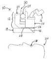
- FIG. 1is a side view of an integrated wavefront sensor and surgical microscope positioned above a patient's head.
- FIG. 2is a top view of the internal components of a wavefront sensor (with the cover removed) according to one embodiment.
- FIG. 3is a perspective view of an aberrated wave traveling through a grating, as well as wave images produced at the fist and second Talbot planes of the grating.
- FIG. 4is a side-view schematic diagram illustrating the operation of an integrated wavefront sensor and surgical microscope according to one embodiment.
- FIG. 5is a front-view schematic diagram of the operation of the integrated wavefront sensor and surgical microscope illustrated in FIG. 4 .
- a surgical device 10includes a surgical microscope 12 , or other suitable viewing device, attached to a wavefront sensor 14 , or other measuring device.
- the surgical microscope 12includes an eyepiece 16 , or other viewing mechanism, which includes one or more optical channels each having one or more optical lenses therein.
- the eyepiece 16is preferably binocular, or stereo, in that it includes two optical channels for allowing a doctor to view an eye 18 of a patient 20 using both of the doctor's eyes (as is best seen in FIG. 5 ). While a monocular eyepiece may alternatively be used, a binocular eyepiece is generally preferred because it provides a higher quality, more complete view to the doctor.
- the surgical microscope 12preferably further includes a light source 22 for providing visible light into the optical pathway of the eyepiece 16 , a focusing knob 24 for adjusting the focus of the microscope 12 , and an objective lens 26 , or other suitable lens, for focusing light beams.
- the objective lens 26is threaded onto the microscope 12 via internal threads on the lens 26 that match external threads on a body 25 of the microscope 12 .
- the wavefront sensor 14may be attached to the microscope 12 in any suitable manner, and is preferably removably attached to the microscope 12 .
- the objective lens 26may be removed from the microscope 12 , and the wavefront sensor 14 , which preferably includes an attachment portion with interior threads that match the exterior threads of the microscope body 25 , may be screwed onto the external threads of the microscope 12 .
- the objective lens 26may then be screwed back onto the external threads beneath the attachment portion of the wavefront sensor 14 .
- One or more fasteners 28may optionally be included to further (or alternatively) secure the wavefront sensor 14 to the microscope 12 .
- the wavefront sensor 14may alternatively be attached to the microscope via screws, bolts, pins, clamps, adhesive, or any other suitable fasteners or attachment means.
- the wavefront sensor 14includes a laser source 40 , or other light source, for creating a beam of light, preferably infrared light.
- the beam of infrared lightis preferably directed by a mirror 42 toward a beam splitter 44 or other suitable device.
- An aperture-sharing elementsuch as a combiner mirror 46 (shown in dashed lines in FIG. 1 ), a beam-splitter, or other similar device, reflects the beam of infrared light down into the eye 18 of the patient 20 .
- the combiner mirror 46preferably reflects infrared light while transmitting visible light so that a doctor can see the patient's eye 18 while looking through the combiner mirror 46 .
- the combiner mirror 46may alternatively be configured to reflect a portion of the visible light spectrum, and/or to transmit a portion of the infrared light spectrum, as described below.
- the infrared light beamAfter the infrared light beam enters the eye 18 , it is reflected, as a wavefront, from the retina of the eye 18 toward the combiner mirror 46 .
- the combiner mirror 46redirects the light beam through the beam splitter 44 toward a first lens 48 .
- the first lens 48relays the infrared light beam off of mirrors 50 and 52 toward a second lens 54 , which directs the light beam onto a diffractive optical component, such as a first reticle or grating 56 .
- the mirrors 42 , 50 , 52are optionally included in the wavefront sensor 14 for re-directing the light beam to maintain it within a compact area, which facilitates the minimization of the overall size and length of the wavefront sensor 14 . A greater or lesser number of mirrors may be included in the wavefront sensor 14 .
- the light beamis diffracted by the first grating 56 , as described in detail below, and preferably travels through another diffractive optical component, such as a second grating 58 , which further diffracts the light beam and creates a final image of the wavefront reflected from the eye 18 .
- a camera 60and/or another light detector or sensor, such as a CCD camera or other suitable device, then captures, records, and/or detects the final image of the eye 18 and converts it into a computer-readable format.
- a computermay then measure and analyze the data to quantify characteristics of the wavefront, and thus, the refractive properties of the eye being examined.
- the wavefront sensor 14may of course include a greater or lesser number of components to meet the requirements of a given system. For example, a greater or lesser number of diffractive gratings or optical lenses may be included in the wavefront sensor 14 . Moreover, additional optical components, such as a camera lens, may optionally be included between the second refractive grating 58 and the camera 60 . Thus, the specific configuration of the wavefront sensor 14 illustrated in FIG. 2 is only one example a suitable wavefront sensor configuration.
- the wavefront sensor 14may be very compact and lightweight, and can produce higher resolution and more accurate alignment registration than a wavefront sensor using larger conventional refractive optics, such as a typical Hartmann-Shack wavefront sensor, as described below.
- the wavefront sensor 14preferably has a length Y that is less than 10 inches, more preferably less than nine inches, more preferably approximately 8.5 inches, and a width X that is preferably less than 5 inches, more preferably approximately 4.5 inches.
- the wavefront sensor 14preferably weighs less than five pounds, more preferably less than 3 pounds or less than 2 pounds.
- the wavefront sensor 14may of course be any other suitable size and/or weight.
- the wavefront sensor 14may be directly or indirectly attached to the surgical microscope 12 to form an integrated surgical device 10 .
- the term “integrated”generally refers to the wavefront sensor 14 and the surgical microscope 12 being incorporated into a unit.
- the integrated surgical device 10may be attached to a balancing mechanism, hanging mechanism, or other suitable device or stand for suspending the integrated device 10 over a patient's head during surgery.
- the balancing mechanism or other supporting devicemay be spring-loaded, counter-balanced, or otherwise balanced for supporting the integrated device 10 . Balancing mechanisms of this nature are commonly used to support and suspend surgical microscopes.
- an attachment portion 30 of the surgical microscope 12may be attached to the balancing mechanism via screws, pins, bolts, or other suitable fasteners, or the integrated device 10 may be attached to the balancing mechanism in any other suitable manner.
- the wavefront sensor 14may be added to an existing surgical microscope 12 that is already supported on a balancing mechanism. The field of view and the focal length of the microscope 12 and/or the wavefront sensor 14 may then be adjusted, if necessary, to optically align the devices relative to one another, as further described below.
- refractive optical componentsare used to redirect a light beam as it passes through a material having a higher density than air, such as a glass refractive lens.
- Diffractive optical componentsconversely, are used to bend a light beam as it encounters the sharp edges of an element, such as the gratings 56 , 58 , and only portions of the light beam occurring near the edges of the grating or other object are redirected.
- Diffractive optical components, such as gratingsare typically significantly smaller and weigh less than refractive optical components, such as refractive lenses.
- the one or more diffractive gratings used in the wavefront sensor 14may be made of any suitable material.
- a preferred diffractive gratingis made from a clear material, such as glass, and has equally spaced perpendicular lines etched or otherwise present on its surface.
- the gratingmay include, for example, a repeating sequence of solid lines each having a width of approximately 12.5 microns, with each pair of lines separated by approximately 12.5 microns of clear glass (the lines and glass spaces on the grating may of course have any other suitable dimensions). The same sequence is repeated with lines running perpendicularly to the first set of lines, such that a pattern similar to that of a standard grid (i.e., a network of uniformly spaced horizontal and perpendicular lines) is formed.
- a standard gridi.e., a network of uniformly spaced horizontal and perpendicular lines
- This redirected lightencounters light that has been redirected by one or more adjacent grating lines.
- Talbot Effecta phenomenon known as the “Talbot Effect” occurs, and a series of dark and light zones form in a space within a predictable distance downstream from the grating, at locations referred to as Talbot planes. This phenomenon is described in detail in U.S. patent application Ser. No. 10/885,504, filed Jul. 6, 2004, as well as in “Fourier Transform Method For Automatic Processing of Moire Deflectograms,” Quiroga et al., Opt. Eng. 38(6) pp.
- the wavefront of light that passed through the gratingis a flat, plane wave
- the dark and light zonesform a perfect replica of the grating, i.e., a virtual image of the grating.
- the shape and size of the virtual image of the gratingis distorted, as shown in FIG. 3 .
- the virtual imagemay be observed by a camera or other light detector, and the images may be measured, typically by a computer, to accurately quantify the characteristics of the wavefront, and hence, the refractive properties of the eye being examined.
- two or more gratingsare aligned in series in the wavefront sensor.
- the virtual image of the gratingis modified to show less resolution, which can compensate for a camera having insufficient resolution.
- the changes in the virtual image of the initial gratingare visually converted into rotational movement, rather than just shrinkage or expansion, and the characteristics of the wavefront may be determined without change in size of the virtual image.
- the virtual image created by the gratingscontains, simultaneously, two sets of information.
- the first set of informationis the virtual image of the grating from which the refractive properties of the eye are characterized, as described above.
- the second set of informationis an almost complete image of the pupil of the eye, which is comprised of the light that passed untouched through the clear spaces of the grating, as well as light that reflected from the surface of the pupil, the sclera, the limbus, and/or other features of the eye if additional illumination is directed to illuminate these features.
- This imageessentially appears to be that of an eye being observed with a grid (i.e., a network of uniformly spaced horizontal and perpendicular lines) between the eye and the observer.
- FIGS. 4 and 5a schematic representation of a process for measuring characteristics of an eye is shown.
- a surgeon (or other doctor) 105looks through a surgical microscope 112 at the eye 125 of a patient.
- the surgical microscope 112preferably includes binocular, or stereo, optics such that it includes two optical viewing channels 116 , 118 (as shown in FIG. 5 ).
- a monocular microscopemay alternatively be used, however. Visible light reflecting from the patient's eye 125 travels along a light pathway 150 , passes through a combiner mirror 120 or similar device, and into the microscope 112 , so that the surgeon may view the patient's eye 125 along visual pathways 122 , 124 .
- a wavefront sensor 114generates an infrared light beam and projects it outwardly along a pathway 145 toward the combiner mirror 120 . While the combiner mirror 120 is shown located outside of the wavefront sensor 114 in the schematic representation of FIGS. 4 and 5 , it is understood that the combiner mirror 120 may be located inside the wavefront sensor 114 , as is shown in FIGS. 1 and 2 , or in any other suitable location where the optical pathways of the surgical microscope 112 and the wavefront sensor 114 meet.
- the combiner mirror 120is preferably transparent to visible light but reflective to infrared light so that it reflects the infrared light beam toward the patient's eye 125 .
- the wavefront sensor 114 and the microscope 112preferably share a common aperture through the combiner mirror 120 .
- a beam splitterthat transmits and reflects both a portion of the visible light and a portion of the infrared light may be used in place of the combiner mirror 120 . Using such a beam splitter would allow the wavefront sensor 114 to operate at a wavelength other than that of the infrared light, such as at a wavelength in the visible spectrum.
- the combiner mirror 120may be configured to reflect a portion of the visible light spectrum, allowing the wavefront sensor 114 to operate in a wavelength range within the visible spectrum, yet prevent that particular wavelength from entering the Microscope 112 .
- the combiner mirror 120may be a narrow pass/reflect combiner, which reflects only a defined wavelength of light having a lower and upper range, thereby allowing the wavefront sensor 114 to operate within the visible light spectrum. The defined visible light spectrum would then be selectively blocked from returning to the microscope 112 , while all light above or below the lower and upper ranges would be freely transmitted.
- the combiner mirror 120reflects the light beam along pathway 150 toward the patient's eye 125 .
- the infrared lightenters the patient's eye 125 and is reflected as a wavefront back along light pathway 150 toward the combiner mirror 120 , which reflects the wavefront along light pathway 145 into the wavefront sensor 114 .
- the wavefront sensor 114measures the wavefront using the process described above, or using a similar process.
- the wavefront sensor 114may have the same configuration and components as the wavefront sensor 14 illustrated in FIG. 2 , or it may have an alternative configuration and may include alternative components.
- the wavefront sensor 114 and the microscope 112are each preferably focused at a point occurring at plane 135 , such that a field of view 155 of the wavefront sensor 114 at least partially overlaps a field of 160 of the microscope 112 .
- the patient's eye 125is preferably located within the overlapping portion of the fields of view 155 , 160 .
- the wavefront sensor 114 and the microscope 112are focused at substantially the same point, such that the center of each field of view 155 , 160 is located at approximately the same point, in the same plane 135 , preferably at or near the center of the patient's eye 125 .
- the surgeon 105may look through the microscope 112 directly into the visual axis of the patient's eye 125 while the wavefront sensor 114 takes measurements of the eye 125 .
- the patientdoes not have to change the gaze angle of the patient's eye 125 at any time during the viewing and measurement processes. This can be very advantageous, especially when the surgical procedure being performed prevents the patient from seeing clearly, or at all, such that it is nearly impossible for the patient to accurately adjust the gaze angle of the patient's eye 125 according to a surgeon's instructions.
- the integrated wavefront sensor and surgical microscope described hereinprovides several advantages. First, it allows a surgeon or other doctor to directly view a patient's eye while the wavefront sensor performs measurements of the refractive characteristics or other optical properties of the patient's eye. As a result, a surgeon can view the results of a given step of a surgical procedure without having to move the patient, the patient's eye, or the device. Indeed, the gaze angle of the patient's eye does not need to change at all during the viewing and measuring steps, and the surgeon's view may be directly aligned with, as opposed to offset from, the visual axis of the patient's eye.
- the integrated devicemay be very compact. Accordingly, the lightweight integrated device can be suspended on a balancing device, or other supporting mechanism, above the head of a patient lying in the supine surgical position, while the surgeon views the patient's eye through the surgical microscope of the integrated device.
- the integrated surgical device 10is preferably not integrated with or otherwise attached to a refractive laser device or other refractive surgical tool.
- the integrated surgical device 10is preferably used primarily for viewing and measuring purposes, while one or more surgical tools used to perform corrective eye procedures are physically separate from the integrated device. Lightweight or otherwise compact surgical tools, however, may optionally be incorporated into the surgical device 10 .
- the wavefront sensor 14 and the surgical microscope 12also preferably do not share an optical pathway to the patient's eye 18 with any other surgical devices.
- the wavefront sensor and the surgical microscopeare preferably (although, not necessarily) separate components that are removably attached to one another, they may each include their own optical components, including any lenses. Thus, the wavefront sensor and the surgical microscope do not need to share a lens, thus providing several advantages and general design flexibility over integrated surgical systems that require one or more lenses to be shared between two or more optical components.
- Some surgical systemsfor example, use a common optical lens to focus light beams from both a wavefront sensor and a refractive laser device.
- a common optical lensBy sharing a lens in this manner, the flexibility to select or design the lens for only a single specific function is lost, as is the ability to design the best possible lens for the overall system application.
- compromisesmust be made to meet the requirements of each component that shares the lens.
- Antireflective coatingsare commonly applied to lenses so that they can function optimally within a certain wavelength. If the laser being used is of a different wavelength than the wavefront sensor illumination beam, however, a common antireflective coating cannot be selected that will work optimally for each of the wavelengths. The same holds true for the wavelength of the wavefront sensor illumination beam in comparison to that of the visible light used to provide visibility through a microscope. Because the surgical device 10 described herein does not require that a lens be shared between the wavefront sensor and the surgical microscope, different antireflective coatings may be applied to the lenses of each of these components, thus allowing for optimal coatings to be selected for each component.
- Another disadvantage of sharing a common lens between two or more optical componentsis the inability to select an optimal focal length, or power, of the lens for each component involved.
- a long focal length lensis desirable in a wavefront sensor to provide sufficient working space for a doctor between the wavefront sensor and the patient.
- a shorter focal length lensis desirable to more tightly focus the laser energy into a shorter plane.
- a system that shares a common lens for these componentsmust compromise or settle on a common focal length, which will not be optimal for one or both of the components.
- an advantageous feature of the surgical device 10is that it does not require a lens to be shared by the wavefront sensor 14 and the surgical microscope 12 .
- the surgical device 10may be used to improve and/or enhance a variety of corrective procedures performed on the eye.
- corrective eye proceduresmay be enhanced by using the surgical device 10 .
- Cataract surgerygenerally involves replacing the natural lens of an eye after the natural lens has become unclear.
- Existing methodstypically require measuring the physical dimensions of the eye with ultrasound, followed by calculating the refractive power of the artificial lens, or other replacement lens, to be inserted. Because the natural lens is unclear, these measurements are often difficult to make. Additionally, variations in the structures of the eye that cannot typically be measured using existing techniques may degrade the calculation.
- the integrated surgical device 10facilitates measurement of the eye's refractive power before and/or immediately after the natural lens is removed, without movement of the patient or the patient's eye, such that the true refractive power of the eye can be more accurately determined. For example, if it is determined that 42 diopters of power are needed for a patient to see clearly at a predetermined distance, and after the natural lens is removed the eye has only 22 diopters of power, then it can easily and accurately be determined that 20 diopters of power must be introduced to the eye via the new lens being inserted.
- the patienttypically has to be moved from the surgical table to a measurement device to make the refractive measurements. Because the patient is typically sedated, and there may be an incision in the patient's eye, and there are sterility requirements to maintain, it is not practical to move the patient between surgical steps.
- the integrated surgical device 10which is preferably suspended above the patient's head, conversely, a surgeon may view the patient's eye through the surgical microscope 12 while the wavefront sensor 14 makes measurements of the eye with the natural lens removed. Accordingly, the patient, as well as the patient's eye, is able to remain motionless in the surgical position during the entire corrective process.
- a further challenge associated with cataract surgeryis that once the replacement lens is inserted into the eye, the replacement lens must be aligned to ensure that it is properly oriented and positioned. If, for example, the replacement lens is not correctly centered, or is not perpendicular to the optical axis of the eye, or if the cylindrical portion (if astigmatic correction to the replacement lens is also being performed) is not oriented to the correct axis, refractive aberrations may be introduced, and the surgical outcome will therefore be degraded.
- the integrated surgical device 10allows the surgeon to make refractive measurements of the eye, after the replacement lens has been inserted, which may be used to guide any required repositioning of the replacement lens.
- viscoelastic cushioning fluidsare typically injected into the eye to protect endothelium cells and other structures, and should be completely removed after the surgery is completed.
- the wavefront sensor 14may be used to identify any remaining viscoelastic pockets (as wave distortions), and can therefore assist the surgeon in removing all of the viscoelastic fluid.
- astigmatismsmay also be reduced during the lens replacement procedure by means other than using a replacement lens with a cylinder component.
- the location and size of any entry woundcould be adjusted, the position of a paracentesis incision could be adjusted, as could any additional lamellar, radial, or arcuate cuts made, all while the surgeon receives feedback from the wavefront sensor 14 that may guide corrections made during the procedure.
- the replacement lensmay be replaced or repaired before the membrane that previously contained the natural lens shrinks and tightens onto the replacement lens.
- a process of introducing relaxing incisions into various locations of the eye, which causes the cornea to flatten out in predictable directions,is often used to eliminate astigmatism of the cornea.
- Such a procedureis often performed at the end of cataract surgery, for example, to eliminate an astigmatism that was induced by the main cataract incision, or that had previously existed.
- the amount of flatteninggenerally varies from patient to patient, however, and is therefore very difficult to precisely predict.
- the wavefront sensor 14can make measurements during the surgical procedure to guide the position, depth, and length of incisions made by the surgeon to achieve desired results.
- Corneal transplant surgeryin which a small central portion, typically 8 to 10 mm in diameter, of the cornea is cut from a donor's eye and grafted into a correspondingly-sized hole cut into a recipient's cornea, may also be improved by using the integrated surgical device 10 .
- refractive errorsare typically difficult to measure. Refractive errors may be introduced if, for example, the donor's corneal tissue is not properly centered, rotated, or oriented in the recipient's cornea, or if the sutures are too tight, too loose, or not evenly tightened. If the recipient's eye is measured after the healing process has completed, refractive errors are difficult, if not impossible, to correct.
- a surgeonmay measure refractive changes in the eye while placing and suturing the donor graft. Indeed, the recipient may remain lying on the surgical table, and the surgeon may look directly into the visual axis of the recipient's eye, while the refractive measurements are being taken. Accordingly, the recipient does not need to be moved at any point during the transplant procedure. Additionally, the donor cornea may be measured by the wavefront sensor to locate its optical axis to assist with better cutting and/or placement of the cornea.
- the integrated surgical device 10may also be used to enhance LASIK (Laser-Assisted In Situ Keratomileusis) refractive surgery, or other laser-assisted surgical procedures.
- LASIKLaser-Assisted In Situ Keratomileusis
- Several variations of laser vision surgeryrequire that a flap be cut from the surface of the cornea to expose the stroma of the cornea to laser treatment.
- the laserreshapes the stroma to a desired contour, after which the flap is replaced over the reshaped stroma. If the flap is not precisely repositioned at its original location, if foreign matter is trapped inside the flap, if a wrinkle is introduced during repositioning, and/or if a host of other repositioning errors occur, then the visual outcome of the procedure will be degraded.
- the integrated surgical device 10allows a surgeon to measure the refractive or optical properties of the eye while the surgeon directly observes the eye, and while the flap is being repositioned, so that any positioning errors or other problems can quickly be corrected.
- the integrated surgical device 10may also be used during a Conductive Keratoplasty (“CK”) procedure.
- CKis a refractive surgical procedure in which highly localized energy pulses, such as heat pulses or radio frequency pulses, are applied to the collagen or stroma of the cornea to reshape the cornea to correct for refractive errors, particularly hyperopia.
- Current methodstypically require that the eye be measured with a conventional refractive device, which provides information regarding how many energy pulses are required to reshape the cornea as desired and identifies which regions of the cornea should receive pulses.
- the patientis then moved to a surgical location where the energy pulses, typically 8 or more, are applied to the cornea, after which the patient is moved back to the measurement device so that the eye may be re-measured.
- the outcome of such a procedureis generally the result of a best prediction, and the actual outcome is rarely exactly as desired due to variability in the response of each individual cornea. If the cornea is under-corrected, more pulses may be added later, but if the cornea is over-corrected, it is difficult, and sometimes impossible, to reverse the over-correction.
- the eye's refractive conditionmay be measured after each pulse is applied (preferably after a certain minimum number of pulses have been applied, for example, after 6 pulses have been applied, since a complete correction will typically not occur until at least a certain minimum number of pulses have been applied), and the surgeon may therefore make guided corrections during the surgical procedure.
- the surgeonmay, for example, alter the position, size, quantity, and/or energy of the pulses applied if measurements taken between successive pulses dictate that such steps should be taken.
- the placement of the pulsesis critically important, and the wavefront sensor may be used to help guide the placement of each energy pulse.
- a procedure for positioning an inlay in a cornea along the eye's visual axismay also be aided by using the integrated surgical device 10 .
- a procedure for positioning an inlay in a cornea along the eye's visual axismay also be aided by using the integrated surgical device 10 .
- an opaque disk or similar structure with a small central apertureis placed in the cornea and trapped inside the flap.
- the inserted diskcreates the effect of a smaller aperture, resulting in the depth of view of the eye being increased. It is, however, extremely difficult to center the disk about the eye's visual axis.
- the wavefront sensor 14can make measurements to determine the exact location of the eye's visual axis while the surgeon directly views the eye, which aids the surgeon in precisely positioning the disk in the proper central location.
- the corneal inlay's central aperturemay be cut into the inlay by the laser after it has been placed in the eye.
- the precise measurements of the wavefront sensor, coupled with the precise control of the laser placementmay result in a more accurate aperture position than if it were manually positioned.
- the integrated surgical device 10may also be used to control corneal distortion during placement of inserts into the cornea.
- myopiafor example, the cornea is too steep and must be flattened.
- slicesare cut into the cornea, after which tiny, curved strips are slid into the stroma of the cornea to exert a straightening force on the cornea that flattens the cornea.
- the wavefront sensor 14can make measurements of the eye while the doctor directly views the eye, allowing the doctor to monitor the degree of flattening and to adjust the process (e.g., to add more or different inserts) midstream.
- the integrated surgical device 10may further be used to measure and view the eye during a procedure for adjusting the tension of the ciliary muscle and/or the ciliary process of the eye.
- rings or other devicesare inserted into the sclera just beyond the limbus of the eye to exert a radially outwardly pulling force on the ciliary muscle.
- the goal of this procedureis to expand the relaxed diameter of the ciliary muscle, which in turn provides added tension in the ciliary muscle and removes some of the slack that has developed therein over the years.
- the wavefront sensor 14can take measurements of the eye while the tensioning procedure is being performed under the surgical microscope 12 , thus guiding the amount of tensioning required to achieve desired results.
- Another corrective procedureinvolves removing tissue from the cornea, via mechanical slicing or another method, to modify the shape of the cornea.
- mechanical tissue removalan incision is made in the side of the cornea to provide a split in the stroma of the cornea.
- a shallow spoon-shaped deviceis then guided into the split, and a blade is used to remove tissue below the spoon's edge plane, resulting in less corneal tissue thickness centrally than peripherally, and thus, corneal flattening (i.e., reduction in myopia).
- the wavefront sensor 14can make measurements during the surgical procedure to guide the process and aid the surgeon in determining how much tissue, at which locations, should be removed.
- the natural lens of the eyemay also be modified to correct refractive defects in the natural lens. Some defects that may occur over time include small opacities, protein buildup, and size increases in the lens.
- One method of modifying the natural lensinvolves removing tissue from the lens to correct vision loss associated with these and other defects. Even a small amount of material removal, however, can result in a large change in refraction.
- the wavefront sensor 14can make measurements during the surgical procedure to guide the process and aid the surgeon in determining how much lens tissue, at which locations, should be removed.
- Optical properties of the natural lensmay also be modified by introducing chemicals, or changing blood sugar levels, in a patient's system.
- Using the integrated surgical device 10 during such a procedureallows a surgeon to measure the amount of change resulting from the introduction of one or more chemicals, which can aid the surgeon in reaching a desired outcome.
- the integrated surgical device 10may also be used to aid in controlling or influencing the resulting shape of a lens that is injected into the eye as a liquid and that cures into a solid.
- a lensis commonly referred to as a “form in the bag” lens.
- Extreme precisionis required to attain the desired resultant shape of the lens using such a procedure.
- the shape and index of refraction of the lenscan be manipulated.
- Using the integrated surgical device 10allows a surgeon looking through the microscope 12 to obtain wavefront data about the lens as it is being formed so that proper course corrections can be made during the curing process.
- Advancementshave been made in the ability to modify or tune the characteristics of an artificial lens after the lens has been inserted into the eye and the eye has healed.
- a surgeon viewing the eye through the microscope 12can make modifications to the artificial lens while the wavefront sensor 14 makes measurements that can guide the procedure.
- the integrated surgical device 10allows a surgeon to view the eye while making wavefront measurements, which aids the surgeon in selecting an appropriate lens and in positioning the lens in the correct central location along the visual axis of the eye. Additionally, the integrated surgical device 10 can verify the overall success or failure of the procedure, which allows the surgeon to make adjustments, while the patient remains on the surgical table, if the outcome is not ideal. This not only improves efficiency, but also allows re-accessing of an incision before it has healed, such that a new incision is not required to make corrections after a non-ideal outcome.
- the wavefront sensor 14 of the integrated surgical device 10may be used to measure the eye before the procedure to help determine a minimum amount of material to add, and may also be used to measure the eye after the material is inserted. The wavefront sensor 14 may then be used to measure the eye at various points of the procedure, which is performed under the surgical microscope 12 , to ensure that the correct amount of material is removed.
- a patient's eyeis measured with a wavefront sensor at a first location, a treatment is calculated and/or planned based on the measurements, and the patient is then moved to a second location where the actual treatment is performed.
- the eyeis measured while the patient is sitting upright, but the treatment is performed while the patient is lying facing upward in a supine position.
- the patient's eyesrotate, or “cyclotort.”
- dye marksare typically placed on the eye while the patient is in the upright position so that the amount of cyclotortion can be measured.
- the wavefront measurementsmay be taken while the patient lies in the supine position, with the cyclotortion present, and while the doctor is viewing the eye. Accordingly, the intermediate step of marking the cornea and compensating for the rotation is not required. The elimination of this step improves the efficiency of the process, and the precision of the orientation of the wavefront registration to the eye is enhanced.
- the integrated surgical device 10may be used to enhance any vision correction procedure by providing a surgeon the ability to view the eye simultaneously with making wavefront measurements of the eye.
- the surgeonmay make wavefront measurements while the patient remains lying in the surgical position, and may course adjustments to a procedure midstream without having to move the patient between surgical steps.
- wavefront sensor 14could include a greater or lesser number of components arranged in any conceivable configuration.
- the inventiontherefore, should not be limited, except by the following claims and their equivalents.
Landscapes
- Health & Medical Sciences (AREA)
- Life Sciences & Earth Sciences (AREA)
- Ophthalmology & Optometry (AREA)
- Surgery (AREA)
- Veterinary Medicine (AREA)
- Heart & Thoracic Surgery (AREA)
- Engineering & Computer Science (AREA)
- Animal Behavior & Ethology (AREA)
- General Health & Medical Sciences (AREA)
- Public Health (AREA)
- Biomedical Technology (AREA)
- Nuclear Medicine, Radiotherapy & Molecular Imaging (AREA)
- Physics & Mathematics (AREA)
- Vascular Medicine (AREA)
- Medical Informatics (AREA)
- Molecular Biology (AREA)
- Optics & Photonics (AREA)
- Biophysics (AREA)
- Transplantation (AREA)
- Pathology (AREA)
- Oral & Maxillofacial Surgery (AREA)
- Eye Examination Apparatus (AREA)
- Microscoopes, Condenser (AREA)
- Prostheses (AREA)
- Investigating Or Analysing Materials By Optical Means (AREA)
Abstract
Description
Claims (9)
Priority Applications (5)
| Application Number | Priority Date | Filing Date | Title |
|---|---|---|---|
| US11/110,653US7883505B2 (en) | 2004-04-20 | 2005-04-20 | Integrated surgical microscope and wavefront sensor |
| US13/021,594US8394083B2 (en) | 2004-04-20 | 2011-02-04 | Integrated surgical microscope and wavefront sensor |
| US13/619,168US8475439B2 (en) | 2004-04-20 | 2012-09-14 | Integrated surgical microscope and wavefront sensor |
| US13/797,365US9107612B2 (en) | 2004-04-20 | 2013-03-12 | Integrated surgical microscope and wavefront sensor |
| US14/799,482US9420949B2 (en) | 2004-04-20 | 2015-07-14 | Integrated surgical microscope and wavefront sensor |
Applications Claiming Priority (2)
| Application Number | Priority Date | Filing Date | Title |
|---|---|---|---|
| US56372704P | 2004-04-20 | 2004-04-20 | |
| US11/110,653US7883505B2 (en) | 2004-04-20 | 2005-04-20 | Integrated surgical microscope and wavefront sensor |
Related Child Applications (1)
| Application Number | Title | Priority Date | Filing Date |
|---|---|---|---|
| US13/021,594ContinuationUS8394083B2 (en) | 2004-04-20 | 2011-02-04 | Integrated surgical microscope and wavefront sensor |
Publications (2)
| Publication Number | Publication Date |
|---|---|
| US20050243276A1 US20050243276A1 (en) | 2005-11-03 |
| US7883505B2true US7883505B2 (en) | 2011-02-08 |
Family
ID=35197474
Family Applications (6)
| Application Number | Title | Priority Date | Filing Date |
|---|---|---|---|
| US11/110,653Active2028-11-13US7883505B2 (en) | 2004-04-20 | 2005-04-20 | Integrated surgical microscope and wavefront sensor |
| US11/110,968AbandonedUS20050241653A1 (en) | 2004-04-20 | 2005-04-20 | Integrated surgical microscope and wavefront sensor |
| US13/021,594Expired - LifetimeUS8394083B2 (en) | 2004-04-20 | 2011-02-04 | Integrated surgical microscope and wavefront sensor |
| US13/619,168Expired - LifetimeUS8475439B2 (en) | 2004-04-20 | 2012-09-14 | Integrated surgical microscope and wavefront sensor |
| US13/797,365Expired - LifetimeUS9107612B2 (en) | 2004-04-20 | 2013-03-12 | Integrated surgical microscope and wavefront sensor |
| US14/799,482Expired - LifetimeUS9420949B2 (en) | 2004-04-20 | 2015-07-14 | Integrated surgical microscope and wavefront sensor |
Family Applications After (5)
| Application Number | Title | Priority Date | Filing Date |
|---|---|---|---|
| US11/110,968AbandonedUS20050241653A1 (en) | 2004-04-20 | 2005-04-20 | Integrated surgical microscope and wavefront sensor |
| US13/021,594Expired - LifetimeUS8394083B2 (en) | 2004-04-20 | 2011-02-04 | Integrated surgical microscope and wavefront sensor |
| US13/619,168Expired - LifetimeUS8475439B2 (en) | 2004-04-20 | 2012-09-14 | Integrated surgical microscope and wavefront sensor |
| US13/797,365Expired - LifetimeUS9107612B2 (en) | 2004-04-20 | 2013-03-12 | Integrated surgical microscope and wavefront sensor |
| US14/799,482Expired - LifetimeUS9420949B2 (en) | 2004-04-20 | 2015-07-14 | Integrated surgical microscope and wavefront sensor |
Country Status (8)
| Country | Link |
|---|---|
| US (6) | US7883505B2 (en) |
| EP (2) | EP1737372B1 (en) |
| JP (1) | JP4972546B2 (en) |
| CN (1) | CN1942146B (en) |
| AU (1) | AU2005234778B2 (en) |
| CA (1) | CA2561388C (en) |
| ES (2) | ES2523429T3 (en) |
| WO (1) | WO2005102200A2 (en) |
Cited By (21)
| Publication number | Priority date | Publication date | Assignee | Title |
|---|---|---|---|---|
| US20050241653A1 (en)* | 2004-04-20 | 2005-11-03 | Wavetec Vision Systems, Inc. | Integrated surgical microscope and wavefront sensor |
| US20100042210A1 (en)* | 2003-04-10 | 2010-02-18 | Tsontcho Ianchulev | Intraoperative Estimation of Intraocular Lens Power |
| US20110007270A1 (en)* | 2009-07-06 | 2011-01-13 | Wavetec Vision Systems Inc. | Objective quality metric for ocular wavefront measurements |
| US20110015541A1 (en)* | 2009-07-14 | 2011-01-20 | Wavetec Vision Systems, Inc. | Determination of the effective lens position of an intraocular lens using aphakic refractive power |
| US20120147325A1 (en)* | 2010-12-10 | 2012-06-14 | Wellhofer Armin | Surgical microscope |
| WO2012170572A1 (en) | 2011-06-06 | 2012-12-13 | Clarity Medical Systems, Inc. | A compact wavefront sensor module and its attachment to or integration with an ophthalmic instrument |
| US8545023B2 (en) | 2009-07-14 | 2013-10-01 | Wavetec Vision Systems, Inc. | Ophthalmic surgery measurement system |
| US8550624B2 (en) | 2008-11-06 | 2013-10-08 | Wavetec Vision Systems, Inc. | Optical angular measurement system for ophthalmic applications and method for positioning of a toric intraocular lens with increased accuracy |
| WO2013165689A1 (en) | 2012-04-30 | 2013-11-07 | Clarity Medical Systems, Inc. | Ophthalmic wavefront sensor operating in parallel sampling and lock-in detection mode |
| US8619405B2 (en) | 2007-10-31 | 2013-12-31 | Wavetec Vision Systems, Inc. | Wavefront sensor |
| US8777413B2 (en) | 2006-01-20 | 2014-07-15 | Clarity Medical Systems, Inc. | Ophthalmic wavefront sensor operating in parallel sampling and lock-in detection mode |
| US9072462B2 (en) | 2012-09-27 | 2015-07-07 | Wavetec Vision Systems, Inc. | Geometric optical power measurement device |
| US9329309B2 (en) | 2012-02-27 | 2016-05-03 | E-Vision Smart Optics, Inc. | Electroactive lens with multiple depth diffractive structures |
| US20170000342A1 (en) | 2015-03-16 | 2017-01-05 | Magic Leap, Inc. | Methods and systems for detecting health conditions by imaging portions of the eye, including the fundus |
| US9622655B2 (en) | 2013-10-10 | 2017-04-18 | Wavetec Vision Systems, Inc. | Correction values for IOL power estimates |
| US10219690B2 (en) | 2011-03-15 | 2019-03-05 | Adventus Technologies, Inc. | Ophthalmic refractor and method of ophthalmic refractor signal analysis |
| US10459231B2 (en) | 2016-04-08 | 2019-10-29 | Magic Leap, Inc. | Augmented reality systems and methods with variable focus lens elements |
| US10962855B2 (en) | 2017-02-23 | 2021-03-30 | Magic Leap, Inc. | Display system with variable power reflector |
| US20210345866A1 (en)* | 2020-05-11 | 2021-11-11 | Welch Allyn, Inc. | Systems and methods for configuring an optical light path |
| WO2022023882A1 (en) | 2020-07-31 | 2022-02-03 | Alcon Inc. | Systems and methods for eye cataract removal |
| WO2024057151A1 (en) | 2022-09-16 | 2024-03-21 | Alcon Inc. | Methods and systems for determining intraocular lens parameters for ophthalmic surgery using an emulated finite elements analysis model |
Families Citing this family (73)
| Publication number | Priority date | Publication date | Assignee | Title |
|---|---|---|---|---|
| DE102004034962A1 (en)* | 2004-07-16 | 2006-02-16 | Carl Zeiss Jena Gmbh | Microscope with increased resolution |
| DE102004034996A1 (en) | 2004-07-16 | 2006-02-02 | Carl Zeiss Jena Gmbh | Scanning microscope with linear scan |
| US10842675B2 (en) | 2006-01-20 | 2020-11-24 | Lensar, Inc. | System and method for treating the structure of the human lens with a laser |
| US9545338B2 (en) | 2006-01-20 | 2017-01-17 | Lensar, Llc. | System and method for improving the accommodative amplitude and increasing the refractive power of the human lens with a laser |
| US8820929B2 (en)* | 2006-01-20 | 2014-09-02 | Clarity Medical Systems, Inc. | Real-time measurement/display/record/playback of wavefront data for use in vision correction procedures |
| US8262646B2 (en) | 2006-01-20 | 2012-09-11 | Lensar, Inc. | System and method for providing the shaped structural weakening of the human lens with a laser |
| US9889043B2 (en) | 2006-01-20 | 2018-02-13 | Lensar, Inc. | System and apparatus for delivering a laser beam to the lens of an eye |
| US8911496B2 (en) | 2006-07-11 | 2014-12-16 | Refocus Group, Inc. | Scleral prosthesis for treating presbyopia and other eye disorders and related devices and methods |
| MX367099B (en) | 2006-07-11 | 2019-08-05 | Refocus Group Inc | Scleral prosthesis for treating presbyopia and other eye disorders and related devices and methods. |
| DE102006038911A1 (en)* | 2006-08-18 | 2008-02-21 | Carl Zeiss Surgical Gmbh | Ophthalmoscopy attachment module and surgical microscope with ophthalmoscopy attachment module |
| NL2000221C2 (en)* | 2006-09-08 | 2008-03-11 | Akkolens Int Bv | Device and method for measuring the optical properties of an eye in combination with an operating microscope. |
| AU2015200832B2 (en)* | 2007-03-13 | 2018-02-22 | Amo Development, Llc | Apparatus for creating ocular surgical and relaxing incisions |
| JP2010520801A (en) | 2007-03-13 | 2010-06-17 | オプティメディカ・コーポレイション | Apparatus for creating eye surgery and a detonation incision |
| US8202272B2 (en) | 2007-07-19 | 2012-06-19 | Avedro, Inc. | Eye therapy system |
| US8992516B2 (en) | 2007-07-19 | 2015-03-31 | Avedro, Inc. | Eye therapy system |
| DE112008002383T5 (en)* | 2007-09-06 | 2010-06-24 | LenSx Lasers, Inc., Aliso Viejo | Precise targeting of surgical photodisruption |
| US8333474B2 (en) | 2007-10-19 | 2012-12-18 | Wavetec Vision Systems, Inc. | Optical instrument alignment system |
| US20140058365A1 (en)* | 2007-12-17 | 2014-02-27 | Josef F. Bille | System and Method for Using Compensating Incisions in Intrastromal Refractive Surgery |
| US8049873B2 (en) | 2008-03-19 | 2011-11-01 | Carl Zeiss Meditec Ag | Surgical microscopy system having an optical coherence tomography facility |
| DE102008034490B4 (en)* | 2008-07-24 | 2018-12-20 | Carl Zeiss Meditec Ag | Eye surgery system and method for preparing and performing eye surgery |
| US8500723B2 (en) | 2008-07-25 | 2013-08-06 | Lensar, Inc. | Liquid filled index matching device for ophthalmic laser procedures |
| US8480659B2 (en) | 2008-07-25 | 2013-07-09 | Lensar, Inc. | Method and system for removal and replacement of lens material from the lens of an eye |
| US9168175B2 (en)* | 2008-09-04 | 2015-10-27 | Vladimir Feingold | Method for laser cutting a corneal pocket |
| US8144958B2 (en) | 2008-09-11 | 2012-03-27 | Carl Zeiss Meditec Ag | Medical systems and methods |
| US8459795B2 (en) | 2008-09-16 | 2013-06-11 | Carl Zeiss Meditec Ag | Measuring system for ophthalmic surgery |
| DE102008047400B9 (en)* | 2008-09-16 | 2011-01-05 | Carl Zeiss Surgical Gmbh | Eye surgery Measurement System |
| EP2346457A4 (en)* | 2008-09-19 | 2012-03-07 | Avedro Inc | Eye therapy system |
| ATE509568T1 (en) | 2008-10-22 | 2011-06-15 | Sensomotoric Instr Ges Fuer Innovative Sensorik Mbh | METHOD AND DEVICE FOR IMAGE PROCESSING FOR COMPUTER-ASSISTED EYE OPERATIONS |
| JP2012508087A (en) | 2008-11-11 | 2012-04-05 | アヴェドロ・インコーポレーテッド | Eye treatment system |
| DE102008062908B4 (en)* | 2008-12-23 | 2011-01-20 | Carl Zeiss Ag | Eye surgery system |
| WO2010115121A1 (en) | 2009-04-02 | 2010-10-07 | Avedro, Inc. | Eye therapy system |
| US8500283B1 (en) | 2009-04-02 | 2013-08-06 | Casimir A. Swinger | Microscope-attachable aberrometer |
| US8342688B1 (en) | 2009-06-15 | 2013-01-01 | Casimir Andrew Swinger | Multifocal capable ophthalmic aberrometer |
| CN102625684B (en)* | 2009-07-24 | 2014-12-10 | 能斯雅有限公司 | Laser system and method for: correction of induced astigmatism and astigmatic correction in association with cataract treatment |
| CN102647954B (en) | 2009-07-24 | 2016-02-03 | 能斯雅有限公司 | A kind ofly provide the system and method for laser irradiation pattern for eye lens |
| US8382745B2 (en) | 2009-07-24 | 2013-02-26 | Lensar, Inc. | Laser system and method for astigmatic corrections in association with cataract treatment |
| JP2013500086A (en) | 2009-07-24 | 2013-01-07 | レンサー, インク. | System and method for performing a procedure using LADAR on an eye lens |
| US8617146B2 (en) | 2009-07-24 | 2013-12-31 | Lensar, Inc. | Laser system and method for correction of induced astigmatism |
| US8758332B2 (en) | 2009-07-24 | 2014-06-24 | Lensar, Inc. | Laser system and method for performing and sealing corneal incisions in the eye |
| DE102009037841B4 (en)* | 2009-08-18 | 2020-01-23 | Carl Zeiss Meditec Ag | Optical system with wavefront analysis system and assembly with wavefront analysis system for a microscope with microscope chassis |
| AU2011203989B2 (en) | 2010-01-08 | 2015-06-11 | Amo Development, Llc | System for modifying eye tissue and intraocular lenses |
| US10085886B2 (en) | 2010-01-08 | 2018-10-02 | Optimedica Corporation | Method and system for modifying eye tissue and intraocular lenses |
| US20110190739A1 (en)* | 2010-01-29 | 2011-08-04 | Lensar, Inc. | Servo controlled docking force device for use in ophthalmic applications |
| WO2011094678A1 (en) | 2010-02-01 | 2011-08-04 | Lensar, Inc. | Purkinjie image-based alignment of suction ring in ophthalmic applications |
| US9622911B2 (en) | 2010-09-30 | 2017-04-18 | Cxl Ophthalmics, Llc | Ophthalmic treatment device, system, and method of use |
| US20120083772A1 (en)* | 2010-09-30 | 2012-04-05 | Curveright Llc | Corneal treatment system and method |
| USD694890S1 (en) | 2010-10-15 | 2013-12-03 | Lensar, Inc. | Laser system for treatment of the eye |
| EP4205633A1 (en) | 2010-10-15 | 2023-07-05 | Lensar, Inc. | System and method of scan controlled illumination of structures within an eye |
| USD695408S1 (en) | 2010-10-15 | 2013-12-10 | Lensar, Inc. | Laser system for treatment of the eye |
| JP2012152469A (en)* | 2011-01-27 | 2012-08-16 | Nidek Co Ltd | Ophthalmic surgical microscope |
| US10463541B2 (en) | 2011-03-25 | 2019-11-05 | Lensar, Inc. | System and method for correcting astigmatism using multiple paired arcuate laser generated corneal incisions |
| US8985768B2 (en) | 2011-11-25 | 2015-03-24 | Ming Lai | Integrated refractor |
| DE102011088039B4 (en)* | 2011-12-08 | 2020-01-16 | Leica Microsystems (Schweiz) Ag | Surgical microscope system for ophthalmology and associated detection unit |
| EP2830554A1 (en) | 2012-03-29 | 2015-02-04 | CXL Ophthalmics, LLC | Ocular cross-linking system and method for sealing corneal wounds |
| EP2830637B1 (en) | 2012-03-29 | 2024-08-21 | Epion Therapeutics, Inc. | Compositions and methods for treating or preventing diseases associated with oxidative stress |
| EP4420725A3 (en) | 2012-03-29 | 2025-04-16 | Epion Therapeutics, Inc. | Ocular treatment solutions, delivery devices and delivery augmentation methods |
| US9332899B2 (en)* | 2012-11-06 | 2016-05-10 | Clarity Medical Systems, Inc. | Electronic eye marking/registration |
| CN103576310B (en)* | 2013-03-15 | 2016-01-27 | 江苏大学 | A kind of auxiliary myopia, astigmatism personnel bore hole use microscopical device |
| CN105473056B (en)* | 2013-07-02 | 2018-10-26 | 麻省理工学院 | The device and method for determining eye prescription |
| DE102013110425A1 (en)* | 2013-09-20 | 2015-04-09 | Karl Storz Gmbh & Co. Kg | eyepiece |
| JP6568873B2 (en) | 2014-02-03 | 2019-08-28 | シャマス,ハンナ | System and method for determining intraocular lens power |
| PT2958532T (en)* | 2014-05-23 | 2017-04-26 | Wavelight Gmbh | Measuring module including an interface for coupling to a laser device |
| US9585561B2 (en) | 2014-07-25 | 2017-03-07 | Novartis Ag | Ophthalmic surgical microscope with adaptive optics for optical wavefront compensation |
| DE112015004256A5 (en) | 2014-09-19 | 2017-06-01 | Carl Zeiss Meditec Ag | An optical coherence tomography system comprising a zoomable Kepler system |
| DE102014014093B4 (en)* | 2014-09-23 | 2018-10-11 | Carl Zeiss Meditec Ag | Eye surgery system and method for operating an eye surgery system |
| WO2016076171A1 (en)* | 2014-11-12 | 2016-05-19 | シャープ株式会社 | Electroluminescent device and method for producing same |
| CN104614848A (en)* | 2015-02-11 | 2015-05-13 | 衡雪源 | Neurosurgical multi-user electronic surgery microscope |
| JP6505539B2 (en)* | 2015-07-27 | 2019-04-24 | 株式会社トプコン | Ophthalmic microscope |
| CN108056892A (en)* | 2018-01-15 | 2018-05-22 | 青岛市市立医院 | A kind of integral type clinical ophthalmology auxiliary device |
| EP4014834A4 (en)* | 2019-08-16 | 2023-06-14 | Topcon Corporation | OPHTHALMIC DEVICE AND OPHTHALMIC SYSTEM |
| CN111772921A (en)* | 2020-08-11 | 2020-10-16 | 曹志君 | Multi-functional stripping pliers for ophthalmologic cataract operation |
| EP4098176A1 (en) | 2021-06-01 | 2022-12-07 | Wavesense Engineering GmbH | Optical apparatus |
| EP4226844A1 (en)* | 2022-02-11 | 2023-08-16 | Leica Instruments (Singapore) Pte. Ltd. | Apparatus and method for an imaging device |
Citations (137)
| Publication number | Priority date | Publication date | Assignee | Title |
|---|---|---|---|---|
| US4125320A (en) | 1976-04-13 | 1978-11-14 | Optische Werke G. Rodenstock | Retinometer |
| US4172662A (en) | 1976-09-08 | 1979-10-30 | Carl Zeiss Stiftung | Eyepiece for measurement of lengths and angles by a microscope |
| US4173398A (en) | 1977-03-11 | 1979-11-06 | Asahi Kogaku Kogyo Kabushiki Kaisha | Optical system for objective eye-examination |
| US4293198A (en) | 1977-09-21 | 1981-10-06 | Canon Kabushiki Kaisha | Eye refractometer |
| US4353625A (en) | 1979-06-02 | 1982-10-12 | Nippon Kogaku K.K. | Eye-refractometer device |
| US4372655A (en) | 1978-09-20 | 1983-02-08 | Canon Kabushiki Kaisha | Automatic eye-refractometer |
| US4376573A (en) | 1979-03-20 | 1983-03-15 | Canon Kabushiki Kaisha | Apparatus for measuring the refractive power of the eye |
| US4390255A (en) | 1978-12-22 | 1983-06-28 | Nippon Kogaku K.K. | Eye-refractometer device |
| US4421391A (en) | 1979-10-05 | 1983-12-20 | Canon Kabushiki Kaisha | Auto eye-refractometer |
| US4459027A (en) | 1980-11-04 | 1984-07-10 | The State Of Israel, Atomic Energy Commission | Method and equipment for mapping radiation deflection |
| US4541697A (en) | 1981-03-03 | 1985-09-17 | Randwal Instrument Co., Inc. | Ophthalmic testing devices |
| US4640596A (en) | 1980-10-31 | 1987-02-03 | Humphrey Instruments, Inc. | Objective refractor for the eye |
| US4650301A (en) | 1980-10-31 | 1987-03-17 | Humphrey Instruments, Inc. | Objective refractor for the eye |
| US4669835A (en) | 1980-10-31 | 1987-06-02 | Humphrey Instruments, Inc. | Objective refractor for the eye |
| US4692003A (en) | 1983-11-07 | 1987-09-08 | Adachi Iwao P | Real-time analysis keratometer |
| US4710193A (en) | 1986-08-18 | 1987-12-01 | David Volk | Accommodating intraocular lens and lens series and method of lens selection |
| US4721379A (en) | 1985-01-16 | 1988-01-26 | Lri L.P. | Apparatus for analysis and correction of abnormal refractive errors of the eye |
| US4730917A (en) | 1982-02-12 | 1988-03-15 | Helmut Krueger | Method and an apparatus for determining the refraction |
| US4964715A (en) | 1987-02-17 | 1990-10-23 | Richards William D | Comparative surgical keratometer |
| US4984883A (en) | 1989-07-21 | 1991-01-15 | Joseph Winocur | Translation insensitive keratometer using moire deflectometry |
| US4995716A (en)* | 1989-03-09 | 1991-02-26 | Par Technology Corporation | Method and apparatus for obtaining the topography of an object |
| US5080477A (en) | 1989-08-28 | 1992-01-14 | Yoshi Adachi | Surface topographer |
| US5157427A (en) | 1990-04-16 | 1992-10-20 | Allergan Humphrey | Objective refractor |
| US5164750A (en) | 1990-11-08 | 1992-11-17 | Yoshi Adachi | Aspheric surface topographer |
| US5206672A (en) | 1990-09-05 | 1993-04-27 | Nestle S.A. | Surgical optometer |
| US5208619A (en) | 1990-11-16 | 1993-05-04 | Allergan Humphrey | Automatic refractor, lensmeter and keratometer utilizing Badal optics |
| US5223863A (en) | 1989-06-12 | 1993-06-29 | Propper Mfg. Co., Inc. | Binocular ophthalmoscope with tilting mirror |
| US5252999A (en) | 1990-10-26 | 1993-10-12 | Nidek Co., Ltd. | Laser apparatus including binocular indirect ophthalmoscope |
| US5258791A (en) | 1990-07-24 | 1993-11-02 | General Electric Company | Spatially resolved objective autorefractometer |
| US5270749A (en) | 1990-11-29 | 1993-12-14 | Canon Kabushiki Kaisha | Opthalmic apparatus for measuring the refractive power of a lens |
| US5282852A (en) | 1992-09-02 | 1994-02-01 | Alcon Surgical, Inc. | Method of calculating the required power of an intraocular lens |
| US5294971A (en) | 1990-02-07 | 1994-03-15 | Leica Heerbrugg Ag | Wave front sensor |
| US5307097A (en) | 1992-11-05 | 1994-04-26 | Kera-Metrics, Inc. | Corneal topography system including single-direction shearing of holograph grating in orthogonal directions |
| US5374193A (en) | 1983-01-25 | 1994-12-20 | Trachtman; Joseph N. | Methods and apparatus for use in alpha training, EMG training and dichotic learning |
| US5576780A (en) | 1992-05-26 | 1996-11-19 | Cain Research Pty. Ltd. | Method for evaluation of length of focus of the eye |
| US5777719A (en) | 1996-12-23 | 1998-07-07 | University Of Rochester | Method and apparatus for improving vision and the resolution of retinal images |
| US5800533A (en) | 1996-03-18 | 1998-09-01 | Harry C. Eggleston | Adjustable intraocular lens implant with magnetic adjustment facilities |
| US5861937A (en) | 1997-05-30 | 1999-01-19 | Nidek Co., Ltd. | Ophthalmic apparatus |
| US5909268A (en) | 1996-10-25 | 1999-06-01 | Nidek Co., Ltd. | Alignment detecting apparatus |
| EP0931504A1 (en) | 1998-01-20 | 1999-07-28 | Nidek Co., Ltd. | Ophthalmic apparatus |
| US5936706A (en) | 1997-08-21 | 1999-08-10 | Kabushiki Kaisha Topcon | Ophthalmic instrument |
| US5963300A (en) | 1998-02-17 | 1999-10-05 | Amt Technologies, Corp. | Ocular biometer |
| US5994687A (en) | 1996-09-17 | 1999-11-30 | Thomson-Csf | System for correction the shape of a wave-front of a laser beam |
| US6002484A (en) | 1999-06-18 | 1999-12-14 | Rozema; Jos J. | Phase contrast aberroscope |
| US6004313A (en) | 1998-06-26 | 1999-12-21 | Visx, Inc. | Patient fixation system and method for laser eye surgery |
| US6007204A (en) | 1998-06-03 | 1999-12-28 | Welch Allyn, Inc. | Compact ocular measuring system |
| US6043885A (en) | 1996-07-12 | 2000-03-28 | Essilor International | Fringe deflectometry apparatus and method |
| US6050687A (en) | 1999-06-11 | 2000-04-18 | 20/10 Perfect Vision Optische Geraete Gmbh | Method and apparatus for measurement of the refractive properties of the human eye |
| US6086204A (en)* | 1999-09-20 | 2000-07-11 | Magnante; Peter C. | Methods and devices to design and fabricate surfaces on contact lenses and on corneal tissue that correct the eye's optical aberrations |
| US6096077A (en) | 1997-08-20 | 2000-08-01 | Thinoptx, Inc. | Deformable intraocular corrective lens |
| US6199986B1 (en) | 1999-10-21 | 2001-03-13 | University Of Rochester | Rapid, automatic measurement of the eye's wave aberration |
| WO2001026591A1 (en) | 1999-10-14 | 2001-04-19 | Iridex Corporation | Therapeutic use of long-pulse laser photocoagulation in combination with other treatment modalities |
| US6251101B1 (en) | 1998-06-26 | 2001-06-26 | Visx, Incorporated | Surgical laser system microscope with separated ocular and objective lenses |
| US6262328B1 (en) | 1999-06-11 | 2001-07-17 | Westinghouse Savannah River Company | Container and method for absorbing and reducing hydrogen concentration |
| US6264328B1 (en) | 1999-10-21 | 2001-07-24 | University Of Rochester | Wavefront sensor with off-axis illumination |
| US6271915B1 (en) | 1996-11-25 | 2001-08-07 | Autonomous Technologies Corporation | Objective measurement and correction of optical systems using wavefront analysis |
| US6270221B1 (en) | 1998-08-19 | 2001-08-07 | Alcon Universal Ltd. | Apparatus and method for measuring vision defects of a human eye |
| US20010041884A1 (en) | 1996-11-25 | 2001-11-15 | Frey Rudolph W. | Method for determining and correcting vision |
| US6338559B1 (en) | 2000-04-28 | 2002-01-15 | University Of Rochester | Apparatus and method for improving vision and retinal imaging |
| US20020016629A1 (en) | 2000-03-20 | 2002-02-07 | Sandstedt Christian A. | Application of wavefront sensor to lenses capable of post-fabrication power modification |
| US6382795B1 (en) | 2000-05-20 | 2002-05-07 | Carl Zeiss, Inc. | Method and apparatus for measuring refractive errors of an eye |
| US6382793B1 (en) | 2000-05-20 | 2002-05-07 | Carl Zeiss, Inc. | Method and apparatus for measuring a wavefront |
| US6409345B1 (en) | 2000-08-08 | 2002-06-25 | Tracey Technologies, Llc | Method and device for synchronous mapping of the total refraction non-homogeneity of the eye and its refractive components |
| US20020082629A1 (en)* | 2000-10-20 | 2002-06-27 | Bausch & Lomb Incorporated | Method and system for improving vision |
| US6419671B1 (en)* | 1999-12-23 | 2002-07-16 | Visx, Incorporated | Optical feedback system for vision correction |
| US20020105617A1 (en) | 2000-05-23 | 2002-08-08 | Sverker Norrby | Methods of obtaining ophthalmic lenses providing the eye with reduced aberrations |
| US6439720B1 (en) | 2000-01-27 | 2002-08-27 | Aoptics, Inc. | Method and apparatus for measuring optical aberrations of the human eye |
| US20020118349A1 (en) | 2000-12-27 | 2002-08-29 | Nikon Corporation | Position detecting method and unit, optical characteristic measuring method and unit, exposure apparatus, and device manufacturing method |
| US20020135736A1 (en) | 2000-12-08 | 2002-09-26 | Visx, Inc. | Direct wavefront-based corneal ablation treatment program |
| US6460997B1 (en) | 2000-05-08 | 2002-10-08 | Alcon Universal Ltd. | Apparatus and method for objective measurements of optical systems using wavefront analysis |
| US20020154272A1 (en)* | 1999-12-23 | 2002-10-24 | Shevlin Fergal Patrick | Display device |
| US20020158508A1 (en)* | 2001-04-27 | 2002-10-31 | Shuzo Watanabe | Pneumatic booster |
| US20020163623A1 (en) | 2001-04-18 | 2002-11-07 | Kabushiki Kaisha Topcon | Opthalmic characteristic measuring apparatus |
| US20030007127A1 (en)* | 2001-06-05 | 2003-01-09 | Adaptive Optics Associates, Inc. | Ophthalmic instrument having an integral wavefront sensor and display device that displays a graphical representation of high order aberrations of the human eye measured by the wavefront sensor |
| US20030025080A1 (en)* | 2001-08-03 | 2003-02-06 | Sting Donald W. | Mid-infrared spectrometer attachment to light microscopes |
| JP2003102689A (en) | 2001-09-21 | 2003-04-08 | Carl Zeiss:Fa | Method and apparatus for measuring optical aberration of eye |
| US6550917B1 (en) | 2000-02-11 | 2003-04-22 | Wavefront Sciences, Inc. | Dynamic range extension techniques for a wavefront sensor including use in ophthalmic measurement |
| US6570143B1 (en)* | 1998-09-23 | 2003-05-27 | Isis Innovation Limited | Wavefront sensing device |
| US6578963B2 (en) | 2000-04-19 | 2003-06-17 | Alcon Universal Ltd. | Wavefront sensor for objective measurement of an optical system and associated methods |
| WO2003050472A1 (en) | 2001-12-10 | 2003-06-19 | Ophthonix, Inc. | Systems and methods for wavefront measurement |
| US6598975B2 (en) | 1998-08-19 | 2003-07-29 | Alcon, Inc. | Apparatus and method for measuring vision defects of a human eye |
| US20030174281A1 (en)* | 2000-10-20 | 2003-09-18 | Herekar Satish Venkatesh | System and method for performing optical corrective procedures with real-time feedback |
| US6626535B2 (en) | 2000-12-29 | 2003-09-30 | Bausch & Lomb Incorporated | Lens-eye model and method for predicting in-vivo lens performance |
| US6634751B2 (en) | 2001-09-10 | 2003-10-21 | Bausch & Lomb Incorporated | Intraocular lens derivation system |
| US6637884B2 (en) | 2001-12-14 | 2003-10-28 | Bausch & Lomb Incorporated | Aberrometer calibration |
| US6658282B1 (en) | 2002-12-19 | 2003-12-02 | Bausch & Lomb Incorporated | Image registration system and method |
| US20030223037A1 (en)* | 2002-05-30 | 2003-12-04 | Visx, Incorporated | Methods and systems for tracking a torsional orientation and position of an eye |
| US20030230710A1 (en)* | 2002-06-15 | 2003-12-18 | Carl Zeiss Jena Gmbh | Microscope, particularly a laser scanning microscope with adaptive optical arrangement |
| US6679606B2 (en) | 2001-10-15 | 2004-01-20 | Alcon, Inc. | Method for determining accommodation |
| US6702806B2 (en) | 2000-04-19 | 2004-03-09 | Alcon, Inc. | Eye registration and astigmatism alignment control systems and method |
| US6705729B2 (en) | 2000-12-22 | 2004-03-16 | Pharmacia Groningen Bv | Methods of obtaining ophthalmic lenses providing the eye with reduced aberrations |
| US6736509B2 (en) | 2001-12-21 | 2004-05-18 | Bausch And Lomb, Inc. | Aberrometer illumination apparatus and method |
| US6736510B1 (en) | 2003-02-04 | 2004-05-18 | Ware Tec Vision Systems, Inc. | Ophthalmic talbot-moire wavefront sensor |
| US6739721B2 (en) | 2001-12-11 | 2004-05-25 | Bausch And Lomb, Inc | Method and apparatus for calibrating and certifying accuracy of a wavefront sensing device |
| US20040167622A1 (en) | 2001-03-26 | 2004-08-26 | Sunalp Murad A. | Temporary refractive intraocular lens and methods of use |
| US6786603B2 (en) | 2002-09-25 | 2004-09-07 | Bausch & Lomb Incorporated | Wavefront-generated custom ophthalmic surfaces |
| WO2004093663A2 (en) | 2003-04-09 | 2004-11-04 | Visx Incorporated | Wavefront calibration analyzer and methods |
| US20040223214A1 (en)* | 2003-05-09 | 2004-11-11 | 3M Innovative Properties Company | Scanning laser microscope with wavefront sensor |
| US6827444B2 (en) | 2000-10-20 | 2004-12-07 | University Of Rochester | Rapid, automatic measurement of the eye's wave aberration |
| US20040263785A1 (en) | 2003-06-16 | 2004-12-30 | Visx, Inc. | Methods and devices for registering optical measurement datasets of an optical system |
| US20050117117A1 (en) | 2003-12-02 | 2005-06-02 | Dan Bourla | Intraoperative biometry |
| US6905641B2 (en) | 2000-09-26 | 2005-06-14 | Calhoun Vision, Inc. | Delivery system for post-operative power adjustment of adjustable lens |
| US20050241653A1 (en) | 2004-04-20 | 2005-11-03 | Wavetec Vision Systems, Inc. | Integrated surgical microscope and wavefront sensor |
| US20050278004A1 (en) | 2004-04-09 | 2005-12-15 | Steinert Roger F | Laser system for vision correction |
| US20060007395A1 (en)* | 2004-07-06 | 2006-01-12 | Mayo William T | System and method for wavefront measurement |
| US6997555B2 (en) | 1999-12-03 | 2006-02-14 | Carl Zeiss Meditec Ag | Method for determining vision defects and for collecting data for correcting vision defects of the eye by interaction of a patient with an examiner and apparatus therefor |
| US20060084956A1 (en)* | 2004-08-10 | 2006-04-20 | Nidek Co., Ltd. | Corneal surgery apparatus |
| US7034949B2 (en) | 2001-12-10 | 2006-04-25 | Ophthonix, Inc. | Systems and methods for wavefront measurement |
| US7044604B1 (en) | 2001-07-11 | 2006-05-16 | Arrowsmith Peter N | Method for determining the power of an intraocular lens used for the treatment of myopia |
| US20060126018A1 (en) | 2004-12-10 | 2006-06-15 | Junzhong Liang | Methods and apparatus for wavefront sensing of human eyes |
| US20060126019A1 (en) | 2004-12-10 | 2006-06-15 | Junzhong Liang | Methods and systems for wavefront analysis |
| US20060135952A1 (en) | 2004-12-21 | 2006-06-22 | Curatu Eugene O | Corrective intraocular lens and associated methods |
| US7068439B2 (en) | 2002-11-20 | 2006-06-27 | Powervision, Inc. | Lens system and method for power adjustment |
| US7070276B2 (en) | 2003-12-04 | 2006-07-04 | Rensselaer Polytechnic Institute | Apparatus and method for accommodative stimulation of an eye and simultaneous ipsilateral accommodative imaging |
| US7077522B2 (en) | 2002-05-03 | 2006-07-18 | University Of Rochester | Sharpness metric for vision quality |
| WO2006081031A2 (en) | 2005-01-27 | 2006-08-03 | Rensselaer Polytechnic Institute | Adaptive scanning optical microscope |
| US20060203198A1 (en) | 2005-03-09 | 2006-09-14 | Advanced Vision Engineering, Inc. | Algorithms and methods for determining aberration-induced vision symptoms in the eye from wave aberration |
| US7111938B2 (en) | 2001-04-27 | 2006-09-26 | Novartis Ag | Automatic lens design and manufacturing system |
| US20060232744A1 (en) | 2005-03-09 | 2006-10-19 | Advanced Vision Engineering, Inc. | Methods for specifying image quality of human eyes from wavefront measurements |
| US7182780B2 (en) | 2000-11-29 | 2007-02-27 | Amo Groningen, B.V. | Device for use in eye surgery |
| US7255442B2 (en) | 2001-08-12 | 2007-08-14 | Imagine Eyes | Device for measuring aberrations in an eye-type system |
| US7303281B2 (en) | 1998-10-07 | 2007-12-04 | Tracey Technologies, Llc | Method and device for determining refractive components and visual function of the eye for vision correction |
| US7336371B1 (en) | 2004-01-29 | 2008-02-26 | Carl Zeiss Smt Ag | Apparatus and method for measuring the wavefront of an optical system |
| US7341348B2 (en) | 2003-03-25 | 2008-03-11 | Bausch & Lomb Incorporated | Moiré aberrometer |
| US7350916B2 (en) | 2005-04-05 | 2008-04-01 | Alcon, Inc. | Intraocular lens |
| US7357509B2 (en) | 2003-04-28 | 2008-04-15 | University Of Rochester | Metrics to predict subjective impact of eye's wave aberration |
| US7377641B2 (en) | 2002-11-29 | 2008-05-27 | Amo Groningen B.V. | Multifocal ophthalmic lens |
| US7380942B2 (en) | 2002-10-04 | 2008-06-03 | Sergiy Molebny | Method for measuring the wave aberrations of the eye |
| US7401919B2 (en) | 2001-11-07 | 2008-07-22 | Carl Zeiss Meditec Ag | Method, device and arrangement for measuring the dynamic behavior of an optical system |
| US7406263B2 (en)* | 2002-10-17 | 2008-07-29 | Aoptix Technologies | Combined wavefront sensor and data detector for a free space optical communications system with adaptive optics |
| US20080231809A1 (en) | 2003-09-23 | 2008-09-25 | Wolfgang Haigis | Method for Measuring Intraocular Lens |
| US7455407B2 (en) | 2000-02-11 | 2008-11-25 | Amo Wavefront Sciences, Llc | System and method of measuring and mapping three dimensional structures |
| US7467869B2 (en) | 2003-04-11 | 2008-12-23 | Bausch & Lomb Incorporated | System and method for acquiring data and aligning and tracking of an eye |
| US7476248B2 (en) | 2004-04-06 | 2009-01-13 | Alcon, Inc. | Method of calculating the required lens power for an opthalmic implant |
| US7490938B2 (en) | 2004-02-09 | 2009-02-17 | Robert Adam Latkany | Method, device and computer program for selecting an intraocular lens for an aphakic eye that has previously been subjected to refractive surgery |
| US7517087B2 (en) | 2001-01-27 | 2009-04-14 | Carl Zeiss Meditec Ag | Method and device for the subjective determination of aberrations of higher order |
| US7556378B1 (en) | 2003-04-10 | 2009-07-07 | Tsontcho Ianchulev | Intraoperative estimation of intraocular lens power |
Family Cites Families (104)
| Publication number | Priority date | Publication date | Assignee | Title |
|---|---|---|---|---|
| GB1209451A (en) | 1967-01-16 | 1970-10-21 | Int Research & Dev Co Ltd | Improvements in and relating to apparatus for measuring parts of the human eye |
| US3947186A (en) | 1975-03-17 | 1976-03-30 | Bradford Howland | Eye-test lens and method |
| US4019813A (en) | 1976-01-19 | 1977-04-26 | Baylor College Of Medicine | Optical apparatus for obtaining measurements of portions of the eye |
| US4911711A (en)* | 1986-12-05 | 1990-03-27 | Taunton Technologies, Inc. | Sculpture apparatus for correcting curvature of the cornea |
| JPH0431813A (en)* | 1990-05-28 | 1992-02-04 | Nikon Corp | Microscope with intermediate zoom lens |
| WO1992001417A1 (en) | 1990-07-19 | 1992-02-06 | Horwitz Larry S | Vision measurement and correction |
| JP2942321B2 (en) | 1990-08-10 | 1999-08-30 | 株式会社ニデック | Transillumination imaging equipment |
| US5329322A (en)* | 1992-05-26 | 1994-07-12 | Yancey Don R | Palm size autorefractor and fundus topographical mapping instrument |
| US5841511A (en) | 1992-06-02 | 1998-11-24 | Eyesys Technologies, Inc. | Method of corneal analysis using a checkered placido apparatus |
| DE4310561A1 (en)* | 1993-03-26 | 1994-09-29 | Klaus Prof Dipl Phys Dietrich | Device and method of determining the visual acuity and refraction, and for observation of the eye surface |
| US5455645A (en)* | 1994-04-11 | 1995-10-03 | Lacrimedics, Inc. | Refractometer for measuring spherical refractive errors |
| US5493109A (en)* | 1994-08-18 | 1996-02-20 | Carl Zeiss, Inc. | Optical coherence tomography assisted ophthalmologic surgical microscope |
| IL112395A (en) | 1995-01-19 | 1998-09-24 | Rotlex 1994 Ltd | Optical device and a method of utilizing such device for optically examining objects |
| SE9501714D0 (en)* | 1995-05-09 | 1995-05-09 | Pharmacia Ab | A method of selecting an intraocular lens to be implanted into an eye |
| US5968094A (en) | 1995-09-18 | 1999-10-19 | Emmetropia, Inc. | Compound intraocular lens |
| JP3592416B2 (en) | 1995-10-31 | 2004-11-24 | 晃敏 吉田 | Measuring device for intraocular substances |
| JP3683059B2 (en) | 1995-12-13 | 2005-08-17 | 晃敏 吉田 | Apparatus for measuring intraocular substances by light generated from the eyeball |
| US5796463A (en)* | 1996-11-27 | 1998-08-18 | The Regents Of The University Of California | Apparatus and method for improving the operation of an autorefractor |
| JPH1124434A (en) | 1997-06-30 | 1999-01-29 | Ricoh Co Ltd | Drive contact / separation mechanism |
| JP3848492B2 (en)* | 1998-09-04 | 2006-11-22 | 株式会社ニデック | Cornea surgery device |
| DE69906779T2 (en)* | 1998-11-13 | 2004-01-29 | Jean Benedikt | METHOD AND DEVICE FOR SIMULTANEOUS DETECTION OF SURFACE OPOGRAPHY AND BIOMETRY OF AN EYE |
| WO2000033729A2 (en) | 1998-12-10 | 2000-06-15 | Carl Zeiss Jena Gmbh | System and method for the non-contacting measurement of the axis length and/or cornea curvature and/or anterior chamber depth of the eye, preferably for intraocular lens calculation |
| DE19857001A1 (en) | 1998-12-10 | 2000-06-15 | Zeiss Carl Jena Gmbh | Non-contact method and device for measuring eye's length of axis, cornea's curvature and eye's main chamber depth assists selection of intra-ocular lenses to be implanted in eye |
| JP2000197607A (en) | 1998-12-30 | 2000-07-18 | Canon Inc | Optometric apparatus |
| US6042232A (en)* | 1999-01-21 | 2000-03-28 | Leica Microsystems Inc. | Automatic optometer evaluation method using data over a wide range of focusing positions |
| JP3040101B1 (en)* | 1999-02-12 | 2000-05-08 | 毅 杉浦 | Ciliary sulcus pad in posterior chamber lens transciliary scleral stitch of the eyeball |
| US6275718B1 (en)* | 1999-03-23 | 2001-08-14 | Philip Lempert | Method and apparatus for imaging and analysis of ocular tissue |
| US6382794B1 (en)* | 1999-09-27 | 2002-05-07 | Carl Zeiss, Inc. | Method and apparatus for mapping a corneal contour and thickness profile |
| CA2712321C (en)* | 1999-10-21 | 2013-07-30 | Technolas Gmbh Ophthalmologische Systeme | Iris recognition and tracking for optical treatment |
| CN101023860B (en)* | 1999-10-21 | 2010-06-16 | 泰克诺拉斯眼科系统有限公司 | Customized corneal profiling |
| US6394999B1 (en)* | 2000-03-13 | 2002-05-28 | Memphis Eye & Cataract Associates Ambulatory Surgery Center | Laser eye surgery system using wavefront sensor analysis to control digital micromirror device (DMD) mirror patterns |
| US6659613B2 (en) | 2000-03-27 | 2003-12-09 | Board Of Regents, The University Of Texas System | Methods and systems for measuring local scattering and aberration properties of optical media |
| CA2409663A1 (en)* | 2000-05-09 | 2001-11-15 | Memphis Eye & Cataract Associates Ambulatory Surgery Center (Dba Meca La Laser And Surgery Center) | Method and system for control of high resolution high speed digital micromirror device for laser refractive eye surgery |
| US6626538B1 (en)* | 2000-07-12 | 2003-09-30 | Peter N. Arrowsmith | Method for determining the power of an intraocular lens used for the treatment of myopia |
| DE10042751A1 (en) | 2000-08-31 | 2002-03-14 | Thomas Hellmuth | System for the contactless measurement of the optical image quality of an eye |
| AU2001296271A1 (en)* | 2000-09-21 | 2002-04-02 | Visx, Inc | Enhanced wavefront ablation system |
| JP3709335B2 (en)* | 2000-09-28 | 2005-10-26 | 株式会社ニデック | Ophthalmic equipment |
| DE60121976D1 (en) | 2000-10-10 | 2006-09-14 | Univ Rochester | DETERMINATION OF THE OKULAR REFECTION BY WAVE FRONT BRAKING DATA |
| US6863667B2 (en)* | 2001-01-29 | 2005-03-08 | Intralase Corp. | Ocular fixation and stabilization device for ophthalmic surgical applications |
| US20020133228A1 (en) | 2001-03-13 | 2002-09-19 | Sarver Edwin J. | Adjustable intraocular lens |
| US6808266B2 (en) | 2001-04-18 | 2004-10-26 | Bausch And Lomb, Inc | Objective manifest refraction |
| US6394605B1 (en)* | 2001-05-23 | 2002-05-28 | Alcon Universal Ltd. | Fogging method for a wavefront sensor |
| US6561648B2 (en) | 2001-05-23 | 2003-05-13 | David E. Thomas | System and method for reconstruction of aberrated wavefronts |
| DE10130278B4 (en)* | 2001-06-26 | 2005-11-03 | Carl Zeiss Meditec Ag | Method and device for representing an operating area during laser operations |
| DE10202509A1 (en)* | 2002-01-23 | 2003-07-31 | Leica Microsystems | Ophthalmic surgical microscope |
| US7609388B2 (en)* | 2002-01-24 | 2009-10-27 | Icos Vision Systems Nv | Spatial wavefront analysis and 3D measurement |
| US6761454B2 (en)* | 2002-02-13 | 2004-07-13 | Ophthonix, Inc. | Apparatus and method for determining objective refraction using wavefront sensing |
| US20050174535A1 (en)* | 2003-02-13 | 2005-08-11 | Lai Shui T. | Apparatus and method for determining subjective responses using objective characterization of vision based on wavefront sensing |
| US7130835B2 (en) | 2002-03-28 | 2006-10-31 | Bausch & Lomb Incorporated | System and method for predictive ophthalmic correction |
| WO2003102519A1 (en) | 2002-05-31 | 2003-12-11 | Wavefront Sciences, Inc. | Methhod and system for sensing and analyzing a wavefront of an optically transmissive system |
| CN2572937Y (en)* | 2002-10-08 | 2003-09-17 | 黄长征 | Ophalmic operating microscope with dioptometry function |
| US7896916B2 (en)* | 2002-11-29 | 2011-03-01 | Amo Groningen B.V. | Multifocal ophthalmic lens |
| JP4233426B2 (en) | 2003-09-30 | 2009-03-04 | 株式会社ニデック | Eye refractive power measuring device |
| EP1694195B1 (en) | 2003-10-28 | 2009-04-08 | Welch Allyn, Inc. | Digital documenting ophthalmoscope |
| US20050105044A1 (en)* | 2003-11-14 | 2005-05-19 | Laurence Warden | Lensometers and wavefront sensors and methods of measuring aberration |
| US7425067B2 (en)* | 2003-11-14 | 2008-09-16 | Ophthonix, Inc. | Ophthalmic diagnostic instrument |
| WO2005057252A2 (en) | 2003-12-02 | 2005-06-23 | Wavetec Vision Systems, Inc. | Interactive refractor incorporating wavefront sensing and adaptive optics |
| ES2416382T3 (en) | 2003-12-12 | 2013-07-31 | Indiana University Research And Technology Corporation | System and procedure to optimize clinical optical prescriptions |
| WO2005077256A1 (en)* | 2004-02-06 | 2005-08-25 | Optovue, Inc. | Optical apparatus and methods for performing eye examinations |
| JP2005237901A (en)* | 2004-03-01 | 2005-09-08 | Nidek Co Ltd | Ophthalmological device |
| US7461938B2 (en) | 2004-06-30 | 2008-12-09 | Ophthonix, Inc. | Apparatus and method for determining sphere and cylinder components of subjective refraction using objective wavefront measurement |
| JP4492858B2 (en) | 2004-07-20 | 2010-06-30 | 株式会社ニデック | Ophthalmic apparatus and intraocular refractive power distribution calculation program |
| DE102004055683B4 (en) | 2004-10-26 | 2006-09-07 | Carl Zeiss Surgical Gmbh | Eye Surgery Microscopy System and Method Therefor |
| SE0402769D0 (en) | 2004-11-12 | 2004-11-12 | Amo Groningen Bv | Method of selecting intraocular lenses |
| KR100686093B1 (en) | 2005-02-03 | 2007-02-23 | 엘지전자 주식회사 | Video device and its channel operation method |
| FR2881520B1 (en) | 2005-02-03 | 2007-10-12 | Lyuboshenko Igor | OBTAINING A PHASE IMAGE FROM AN INTENSITY IMAGE |
| US20060279699A1 (en) | 2005-06-14 | 2006-12-14 | Advanced Vision Engineering, Inc | Wavefront fusion algorithms for refractive vision correction and vision diagnosis |
| US7441901B2 (en) | 2005-06-14 | 2008-10-28 | Advanced Vision Engineering, Inc. | Multitask vision architecture for refractive vision corrections |
| KR101248492B1 (en) | 2005-07-29 | 2013-04-03 | 알콘 리프랙티브호리존스, 인코포레이티드 | Ophthalmic device positioning system and associated methods |
| BRPI0614915A2 (en) | 2005-07-29 | 2011-04-19 | Alcon Refractive Horizons Inc | ophthalmic device lateral positioning system and associated methods |
| WO2007035334A2 (en) | 2005-09-19 | 2007-03-29 | Advanced Vision Engineering, Inc. | Methods and apparatus for comprehensive vision diagnosis |
| JP5085858B2 (en) | 2005-09-27 | 2012-11-28 | 株式会社ニデック | Eye refractive power measuring device |
| US20070083261A1 (en) | 2005-10-07 | 2007-04-12 | Colvard David M | Method of maintaining the preoperative dimensions of the eye in an intraocular lens placement procedure |
| US8100530B2 (en) | 2006-01-20 | 2012-01-24 | Clarity Medical Systems, Inc. | Optimizing vision correction procedures |
| US7445335B2 (en) | 2006-01-20 | 2008-11-04 | Clarity Medical Systems, Inc. | Sequential wavefront sensor |
| US7475989B2 (en) | 2006-03-14 | 2009-01-13 | Amo Manufacturing Usa, Llc | Shack-Hartmann based integrated autorefraction and wavefront measurements of the eye |
| EP2008058B1 (en) | 2006-04-07 | 2012-12-05 | Abbott Medical Optics Inc. | Geometric measurement system and method of measuring a geometric characteristic of an object |
| ES2817950T3 (en) | 2006-04-11 | 2021-04-08 | Cognoptix Inc | Eye imaging |
| US20080033546A1 (en) | 2006-05-31 | 2008-02-07 | Junzhong Liang | Methods and apparatus for improving vision |
| US20080004610A1 (en) | 2006-06-30 | 2008-01-03 | David Miller | System for calculating IOL power |
| NL2000221C2 (en) | 2006-09-08 | 2008-03-11 | Akkolens Int Bv | Device and method for measuring the optical properties of an eye in combination with an operating microscope. |
| US7478908B2 (en) | 2006-09-27 | 2009-01-20 | Bausch & Lomb Incorporated | Apparatus and method for determining a position of an eye |
| US20080084541A1 (en) | 2006-10-06 | 2008-04-10 | Ming Lai | Ophthalmic system and method |
| EP2087310B1 (en) | 2006-11-09 | 2018-08-15 | AMO WaveFront Sciences, LLC | Method and apparatus for obtaining the distance from an optical measurement instrument to and object under test |
| CA2687100C (en) | 2007-05-11 | 2016-04-12 | Charles E. Campbell | Combined wavefront and topography systems and methods |
| US7832864B2 (en) | 2007-06-15 | 2010-11-16 | The Arizona Board Of Regents On Behalf Of The University Of Arizona | Inverse optical design |
| US7976163B2 (en) | 2007-06-27 | 2011-07-12 | Amo Wavefront Sciences Llc | System and method for measuring corneal topography |
| US8414123B2 (en) | 2007-08-13 | 2013-04-09 | Novartis Ag | Toric lenses alignment using pre-operative images |
| US20090096987A1 (en) | 2007-10-10 | 2009-04-16 | Ming Lai | Eye Measurement Apparatus and a Method of Using Same |
| US8333474B2 (en)* | 2007-10-19 | 2012-12-18 | Wavetec Vision Systems, Inc. | Optical instrument alignment system |
| US7594729B2 (en) | 2007-10-31 | 2009-09-29 | Wf Systems, Llc | Wavefront sensor |
| US8128228B2 (en) | 2007-12-19 | 2012-03-06 | Wf Systems Llc | Devices and methods for measuring axial distances |
| US8480659B2 (en) | 2008-07-25 | 2013-07-09 | Lensar, Inc. | Method and system for removal and replacement of lens material from the lens of an eye |
| US8657445B2 (en) | 2008-09-11 | 2014-02-25 | Iol Innovations Aps | System and method for determining and predicting IOL power in situ |
| JP5335922B2 (en) | 2008-09-29 | 2013-11-06 | サイファイ メドテック エッセ.エッレ.エッレ. | Systems and methods for designing and implanting customized biometric intraocular lenses |
| US8550624B2 (en) | 2008-11-06 | 2013-10-08 | Wavetec Vision Systems, Inc. | Optical angular measurement system for ophthalmic applications and method for positioning of a toric intraocular lens with increased accuracy |
| DE102008062908B4 (en) | 2008-12-23 | 2011-01-20 | Carl Zeiss Ag | Eye surgery system |
| US8876290B2 (en) | 2009-07-06 | 2014-11-04 | Wavetec Vision Systems, Inc. | Objective quality metric for ocular wavefront measurements |
| JP5837489B2 (en) | 2009-07-14 | 2015-12-24 | ウェーブテック・ビジョン・システムズ・インコーポレイテッドWavetec Vision Systems, Inc. | Ophthalmic equipment |
| ES2524618T3 (en) | 2009-07-14 | 2014-12-10 | Wavetec Vision Systems, Inc. | Determination of the effective position of the lens of an intraocular lens using afractive refractive power |
| DE102009037841B4 (en) | 2009-08-18 | 2020-01-23 | Carl Zeiss Meditec Ag | Optical system with wavefront analysis system and assembly with wavefront analysis system for a microscope with microscope chassis |
| US9072462B2 (en) | 2012-09-27 | 2015-07-07 | Wavetec Vision Systems, Inc. | Geometric optical power measurement device |
| US9959786B2 (en) | 2012-09-27 | 2018-05-01 | Applied Medical Resources Corporation | Surgical training model for laparoscopic procedures |
| JP2014079517A (en) | 2012-10-18 | 2014-05-08 | Canon Inc | Ophthalmic equipment |
- 2005
- 2005-04-20USUS11/110,653patent/US7883505B2/enactiveActive
- 2005-04-20ESES05737636.0Tpatent/ES2523429T3/ennot_activeExpired - Lifetime
- 2005-04-20AUAU2005234778Apatent/AU2005234778B2/ennot_activeExpired
- 2005-04-20EPEP05737636.0Apatent/EP1737372B1/ennot_activeExpired - Lifetime
- 2005-04-20EPEP12151139.8Apatent/EP2444021B8/ennot_activeExpired - Lifetime
- 2005-04-20CACA2561388Apatent/CA2561388C/ennot_activeExpired - Lifetime
- 2005-04-20ESES12151139.8Tpatent/ES2665536T3/ennot_activeExpired - Lifetime
- 2005-04-20USUS11/110,968patent/US20050241653A1/ennot_activeAbandoned
- 2005-04-20WOPCT/US2005/013550patent/WO2005102200A2/ennot_activeApplication Discontinuation
- 2005-04-20JPJP2007509613Apatent/JP4972546B2/ennot_activeExpired - Lifetime
- 2005-04-20CNCN2005800118036Apatent/CN1942146B/ennot_activeExpired - Lifetime
- 2011
- 2011-02-04USUS13/021,594patent/US8394083B2/ennot_activeExpired - Lifetime
- 2012
- 2012-09-14USUS13/619,168patent/US8475439B2/ennot_activeExpired - Lifetime
- 2013
- 2013-03-12USUS13/797,365patent/US9107612B2/ennot_activeExpired - Lifetime
- 2015
- 2015-07-14USUS14/799,482patent/US9420949B2/ennot_activeExpired - Lifetime
Patent Citations (165)
| Publication number | Priority date | Publication date | Assignee | Title |
|---|---|---|---|---|
| US4125320A (en) | 1976-04-13 | 1978-11-14 | Optische Werke G. Rodenstock | Retinometer |
| US4172662A (en) | 1976-09-08 | 1979-10-30 | Carl Zeiss Stiftung | Eyepiece for measurement of lengths and angles by a microscope |
| US4173398A (en) | 1977-03-11 | 1979-11-06 | Asahi Kogaku Kogyo Kabushiki Kaisha | Optical system for objective eye-examination |
| US4293198A (en) | 1977-09-21 | 1981-10-06 | Canon Kabushiki Kaisha | Eye refractometer |
| US4372655A (en) | 1978-09-20 | 1983-02-08 | Canon Kabushiki Kaisha | Automatic eye-refractometer |
| US4390255A (en) | 1978-12-22 | 1983-06-28 | Nippon Kogaku K.K. | Eye-refractometer device |
| US4376573A (en) | 1979-03-20 | 1983-03-15 | Canon Kabushiki Kaisha | Apparatus for measuring the refractive power of the eye |
| US4353625A (en) | 1979-06-02 | 1982-10-12 | Nippon Kogaku K.K. | Eye-refractometer device |
| US4421391A (en) | 1979-10-05 | 1983-12-20 | Canon Kabushiki Kaisha | Auto eye-refractometer |
| US4640596A (en) | 1980-10-31 | 1987-02-03 | Humphrey Instruments, Inc. | Objective refractor for the eye |
| US4650301A (en) | 1980-10-31 | 1987-03-17 | Humphrey Instruments, Inc. | Objective refractor for the eye |
| US4669835A (en) | 1980-10-31 | 1987-06-02 | Humphrey Instruments, Inc. | Objective refractor for the eye |
| US4459027A (en) | 1980-11-04 | 1984-07-10 | The State Of Israel, Atomic Energy Commission | Method and equipment for mapping radiation deflection |
| US4541697A (en) | 1981-03-03 | 1985-09-17 | Randwal Instrument Co., Inc. | Ophthalmic testing devices |
| US4730917A (en) | 1982-02-12 | 1988-03-15 | Helmut Krueger | Method and an apparatus for determining the refraction |
| US5374193A (en) | 1983-01-25 | 1994-12-20 | Trachtman; Joseph N. | Methods and apparatus for use in alpha training, EMG training and dichotic learning |
| US4692003A (en) | 1983-11-07 | 1987-09-08 | Adachi Iwao P | Real-time analysis keratometer |
| US4721379A (en) | 1985-01-16 | 1988-01-26 | Lri L.P. | Apparatus for analysis and correction of abnormal refractive errors of the eye |
| US4710193A (en) | 1986-08-18 | 1987-12-01 | David Volk | Accommodating intraocular lens and lens series and method of lens selection |
| US4964715A (en) | 1987-02-17 | 1990-10-23 | Richards William D | Comparative surgical keratometer |
| US4995716A (en)* | 1989-03-09 | 1991-02-26 | Par Technology Corporation | Method and apparatus for obtaining the topography of an object |
| US5223863A (en) | 1989-06-12 | 1993-06-29 | Propper Mfg. Co., Inc. | Binocular ophthalmoscope with tilting mirror |
| US4984883A (en) | 1989-07-21 | 1991-01-15 | Joseph Winocur | Translation insensitive keratometer using moire deflectometry |
| US5080477A (en) | 1989-08-28 | 1992-01-14 | Yoshi Adachi | Surface topographer |
| US5294971A (en) | 1990-02-07 | 1994-03-15 | Leica Heerbrugg Ag | Wave front sensor |
| US5157427A (en) | 1990-04-16 | 1992-10-20 | Allergan Humphrey | Objective refractor |
| US5258791A (en) | 1990-07-24 | 1993-11-02 | General Electric Company | Spatially resolved objective autorefractometer |
| US5206672A (en) | 1990-09-05 | 1993-04-27 | Nestle S.A. | Surgical optometer |
| US5450143A (en) | 1990-09-05 | 1995-09-12 | Nestle S.A. | Surgical optometer |
| US5252999A (en) | 1990-10-26 | 1993-10-12 | Nidek Co., Ltd. | Laser apparatus including binocular indirect ophthalmoscope |
| US5164750A (en) | 1990-11-08 | 1992-11-17 | Yoshi Adachi | Aspheric surface topographer |
| US5208619A (en) | 1990-11-16 | 1993-05-04 | Allergan Humphrey | Automatic refractor, lensmeter and keratometer utilizing Badal optics |
| US5270749A (en) | 1990-11-29 | 1993-12-14 | Canon Kabushiki Kaisha | Opthalmic apparatus for measuring the refractive power of a lens |
| US5576780A (en) | 1992-05-26 | 1996-11-19 | Cain Research Pty. Ltd. | Method for evaluation of length of focus of the eye |
| US5282852A (en) | 1992-09-02 | 1994-02-01 | Alcon Surgical, Inc. | Method of calculating the required power of an intraocular lens |
| US5307097A (en) | 1992-11-05 | 1994-04-26 | Kera-Metrics, Inc. | Corneal topography system including single-direction shearing of holograph grating in orthogonal directions |
| US5800533A (en) | 1996-03-18 | 1998-09-01 | Harry C. Eggleston | Adjustable intraocular lens implant with magnetic adjustment facilities |
| US6043885A (en) | 1996-07-12 | 2000-03-28 | Essilor International | Fringe deflectometry apparatus and method |
| US5994687A (en) | 1996-09-17 | 1999-11-30 | Thomson-Csf | System for correction the shape of a wave-front of a laser beam |
| US5909268A (en) | 1996-10-25 | 1999-06-01 | Nidek Co., Ltd. | Alignment detecting apparatus |
| US6271915B1 (en) | 1996-11-25 | 2001-08-07 | Autonomous Technologies Corporation | Objective measurement and correction of optical systems using wavefront analysis |
| US20010041884A1 (en) | 1996-11-25 | 2001-11-15 | Frey Rudolph W. | Method for determining and correcting vision |
| US6948818B2 (en) | 1996-12-23 | 2005-09-27 | University Of Rochester | Method and apparatus for improving vision and the resolution of retinal images |
| US5949521A (en) | 1996-12-23 | 1999-09-07 | University Of Rochester | Method and apparatus for improving vision and the resolution of retinal images |
| US6095651A (en) | 1996-12-23 | 2000-08-01 | University Of Rochester | Method and apparatus for improving vision and the resolution of retinal images |
| US6379005B1 (en) | 1996-12-23 | 2002-04-30 | University Of Rochester | Method and apparatus for improving vision and the resolution of retinal images |
| US5777719A (en) | 1996-12-23 | 1998-07-07 | University Of Rochester | Method and apparatus for improving vision and the resolution of retinal images |
| US20090002628A1 (en) | 1996-12-23 | 2009-01-01 | University Of Rochester | Method and apparatus improving vision and the resolution of retinal images |
| US7416305B2 (en) | 1996-12-23 | 2008-08-26 | University Of Rochester | Method and apparatus for improving vision and the resolution of retinal images |
| US5861937A (en) | 1997-05-30 | 1999-01-19 | Nidek Co., Ltd. | Ophthalmic apparatus |
| US6096077A (en) | 1997-08-20 | 2000-08-01 | Thinoptx, Inc. | Deformable intraocular corrective lens |
| US5936706A (en) | 1997-08-21 | 1999-08-10 | Kabushiki Kaisha Topcon | Ophthalmic instrument |
| EP0931504A1 (en) | 1998-01-20 | 1999-07-28 | Nidek Co., Ltd. | Ophthalmic apparatus |
| US5963300A (en) | 1998-02-17 | 1999-10-05 | Amt Technologies, Corp. | Ocular biometer |
| US6007204A (en) | 1998-06-03 | 1999-12-28 | Welch Allyn, Inc. | Compact ocular measuring system |
| US6251101B1 (en) | 1998-06-26 | 2001-06-26 | Visx, Incorporated | Surgical laser system microscope with separated ocular and objective lenses |
| US6004313A (en) | 1998-06-26 | 1999-12-21 | Visx, Inc. | Patient fixation system and method for laser eye surgery |
| US6598975B2 (en) | 1998-08-19 | 2003-07-29 | Alcon, Inc. | Apparatus and method for measuring vision defects of a human eye |
| US6270221B1 (en) | 1998-08-19 | 2001-08-07 | Alcon Universal Ltd. | Apparatus and method for measuring vision defects of a human eye |
| US6570143B1 (en)* | 1998-09-23 | 2003-05-27 | Isis Innovation Limited | Wavefront sensing device |
| US7303281B2 (en) | 1998-10-07 | 2007-12-04 | Tracey Technologies, Llc | Method and device for determining refractive components and visual function of the eye for vision correction |
| US6262328B1 (en) | 1999-06-11 | 2001-07-17 | Westinghouse Savannah River Company | Container and method for absorbing and reducing hydrogen concentration |
| US6155684A (en) | 1999-06-11 | 2000-12-05 | Perfect Vision Optische Geraete Gmbh | Method and apparatus for precompensating the refractive properties of the human eye with adaptive optical feedback control |
| US6050687A (en) | 1999-06-11 | 2000-04-18 | 20/10 Perfect Vision Optische Geraete Gmbh | Method and apparatus for measurement of the refractive properties of the human eye |
| US6002484A (en) | 1999-06-18 | 1999-12-14 | Rozema; Jos J. | Phase contrast aberroscope |
| US6086204A (en)* | 1999-09-20 | 2000-07-11 | Magnante; Peter C. | Methods and devices to design and fabricate surfaces on contact lenses and on corneal tissue that correct the eye's optical aberrations |
| WO2001026591A1 (en) | 1999-10-14 | 2001-04-19 | Iridex Corporation | Therapeutic use of long-pulse laser photocoagulation in combination with other treatment modalities |
| US6264328B1 (en) | 1999-10-21 | 2001-07-24 | University Of Rochester | Wavefront sensor with off-axis illumination |
| US6199986B1 (en) | 1999-10-21 | 2001-03-13 | University Of Rochester | Rapid, automatic measurement of the eye's wave aberration |
| US6299311B1 (en) | 1999-10-21 | 2001-10-09 | University Of Rochester | Rapid, automatic measurement of the eye's wave aberration |
| US6997555B2 (en) | 1999-12-03 | 2006-02-14 | Carl Zeiss Meditec Ag | Method for determining vision defects and for collecting data for correcting vision defects of the eye by interaction of a patient with an examiner and apparatus therefor |
| US6419671B1 (en)* | 1999-12-23 | 2002-07-16 | Visx, Incorporated | Optical feedback system for vision correction |
| US6793654B2 (en) | 1999-12-23 | 2004-09-21 | Visx, Inc. | Optical feedback system for vision correction |
| US20020154272A1 (en)* | 1999-12-23 | 2002-10-24 | Shevlin Fergal Patrick | Display device |
| US6439720B1 (en) | 2000-01-27 | 2002-08-27 | Aoptics, Inc. | Method and apparatus for measuring optical aberrations of the human eye |
| US7455407B2 (en) | 2000-02-11 | 2008-11-25 | Amo Wavefront Sciences, Llc | System and method of measuring and mapping three dimensional structures |
| US6550917B1 (en) | 2000-02-11 | 2003-04-22 | Wavefront Sciences, Inc. | Dynamic range extension techniques for a wavefront sensor including use in ophthalmic measurement |
| US20020016629A1 (en) | 2000-03-20 | 2002-02-07 | Sandstedt Christian A. | Application of wavefront sensor to lenses capable of post-fabrication power modification |
| US6702806B2 (en) | 2000-04-19 | 2004-03-09 | Alcon, Inc. | Eye registration and astigmatism alignment control systems and method |
| US6578963B2 (en) | 2000-04-19 | 2003-06-17 | Alcon Universal Ltd. | Wavefront sensor for objective measurement of an optical system and associated methods |
| US6338559B1 (en) | 2000-04-28 | 2002-01-15 | University Of Rochester | Apparatus and method for improving vision and retinal imaging |
| US6460997B1 (en) | 2000-05-08 | 2002-10-08 | Alcon Universal Ltd. | Apparatus and method for objective measurements of optical systems using wavefront analysis |
| US6497483B2 (en) | 2000-05-08 | 2002-12-24 | Alcon, Inc. | Apparatus and method for objective measurement of optical systems using wavefront analysis |
| US6382793B1 (en) | 2000-05-20 | 2002-05-07 | Carl Zeiss, Inc. | Method and apparatus for measuring a wavefront |
| US6382795B1 (en) | 2000-05-20 | 2002-05-07 | Carl Zeiss, Inc. | Method and apparatus for measuring refractive errors of an eye |
| US20090036980A1 (en) | 2000-05-23 | 2009-02-05 | Amo Groningen Bv | Methods of obtaining ophthalmic lenses providing the eye with reduced aberrations |
| US20040088050A1 (en) | 2000-05-23 | 2004-05-06 | Sverker Norrby | Methods of obtaining ophthalmic lenses providing the eye with reduced aberrations |
| US6609793B2 (en) | 2000-05-23 | 2003-08-26 | Pharmacia Groningen Bv | Methods of obtaining ophthalmic lenses providing the eye with reduced aberrations |
| US20020105617A1 (en) | 2000-05-23 | 2002-08-08 | Sverker Norrby | Methods of obtaining ophthalmic lenses providing the eye with reduced aberrations |
| US6409345B1 (en) | 2000-08-08 | 2002-06-25 | Tracey Technologies, Llc | Method and device for synchronous mapping of the total refraction non-homogeneity of the eye and its refractive components |
| US6905641B2 (en) | 2000-09-26 | 2005-06-14 | Calhoun Vision, Inc. | Delivery system for post-operative power adjustment of adjustable lens |
| US20050251115A1 (en)* | 2000-10-20 | 2005-11-10 | Cox Ian G | Method and system for improving vision |
| US6827444B2 (en) | 2000-10-20 | 2004-12-07 | University Of Rochester | Rapid, automatic measurement of the eye's wave aberration |
| US6926710B2 (en) | 2000-10-20 | 2005-08-09 | Bausch And Lomb Incorporated | Method and system for improving vision |
| US6908196B2 (en) | 2000-10-20 | 2005-06-21 | Wavefront Sciences, Inc. | System and method for performing optical corrective procedures with real-time feedback |
| US20030174281A1 (en)* | 2000-10-20 | 2003-09-18 | Herekar Satish Venkatesh | System and method for performing optical corrective procedures with real-time feedback |
| US20020082629A1 (en)* | 2000-10-20 | 2002-06-27 | Bausch & Lomb Incorporated | Method and system for improving vision |
| US7182780B2 (en) | 2000-11-29 | 2007-02-27 | Amo Groningen, B.V. | Device for use in eye surgery |
| US20020135736A1 (en) | 2000-12-08 | 2002-09-26 | Visx, Inc. | Direct wavefront-based corneal ablation treatment program |
| US6705729B2 (en) | 2000-12-22 | 2004-03-16 | Pharmacia Groningen Bv | Methods of obtaining ophthalmic lenses providing the eye with reduced aberrations |
| US20020118349A1 (en) | 2000-12-27 | 2002-08-29 | Nikon Corporation | Position detecting method and unit, optical characteristic measuring method and unit, exposure apparatus, and device manufacturing method |
| US6626535B2 (en) | 2000-12-29 | 2003-09-30 | Bausch & Lomb Incorporated | Lens-eye model and method for predicting in-vivo lens performance |
| US7517087B2 (en) | 2001-01-27 | 2009-04-14 | Carl Zeiss Meditec Ag | Method and device for the subjective determination of aberrations of higher order |
| US20040167622A1 (en) | 2001-03-26 | 2004-08-26 | Sunalp Murad A. | Temporary refractive intraocular lens and methods of use |
| US20020163623A1 (en) | 2001-04-18 | 2002-11-07 | Kabushiki Kaisha Topcon | Opthalmic characteristic measuring apparatus |
| US20020158508A1 (en)* | 2001-04-27 | 2002-10-31 | Shuzo Watanabe | Pneumatic booster |
| US7111938B2 (en) | 2001-04-27 | 2006-09-26 | Novartis Ag | Automatic lens design and manufacturing system |
| US6572230B2 (en) | 2001-06-05 | 2003-06-03 | Metrologic Instruments, Inc. | Ophthalmic instrument having an integral wavefront sensor and display device that displays a graphical representation of high order aberrations of the human eye measured by the wavefront sensor |
| US20030007127A1 (en)* | 2001-06-05 | 2003-01-09 | Adaptive Optics Associates, Inc. | Ophthalmic instrument having an integral wavefront sensor and display device that displays a graphical representation of high order aberrations of the human eye measured by the wavefront sensor |
| US7350920B2 (en) | 2001-06-05 | 2008-04-01 | Bruce Martin Levine | Wavefront sensing apparatus with adaptive optics |
| US6609794B2 (en) | 2001-06-05 | 2003-08-26 | Adaptive Optics Associates, Inc. | Method of treating the human eye with a wavefront sensor-based ophthalmic instrument |
| US7044604B1 (en) | 2001-07-11 | 2006-05-16 | Arrowsmith Peter N | Method for determining the power of an intraocular lens used for the treatment of myopia |
| US20030025080A1 (en)* | 2001-08-03 | 2003-02-06 | Sting Donald W. | Mid-infrared spectrometer attachment to light microscopes |
| US7255442B2 (en) | 2001-08-12 | 2007-08-14 | Imagine Eyes | Device for measuring aberrations in an eye-type system |
| US6634751B2 (en) | 2001-09-10 | 2003-10-21 | Bausch & Lomb Incorporated | Intraocular lens derivation system |
| JP2003102689A (en) | 2001-09-21 | 2003-04-08 | Carl Zeiss:Fa | Method and apparatus for measuring optical aberration of eye |
| US6575572B2 (en) | 2001-09-21 | 2003-06-10 | Carl Zeiss Ophthalmic Systems, Inc. | Method and apparatus for measuring optical aberrations of an eye |
| US6679606B2 (en) | 2001-10-15 | 2004-01-20 | Alcon, Inc. | Method for determining accommodation |
| US7401919B2 (en) | 2001-11-07 | 2008-07-22 | Carl Zeiss Meditec Ag | Method, device and arrangement for measuring the dynamic behavior of an optical system |
| US7034949B2 (en) | 2001-12-10 | 2006-04-25 | Ophthonix, Inc. | Systems and methods for wavefront measurement |
| WO2003050472A1 (en) | 2001-12-10 | 2003-06-19 | Ophthonix, Inc. | Systems and methods for wavefront measurement |
| US6781681B2 (en) | 2001-12-10 | 2004-08-24 | Ophthonix, Inc. | System and method for wavefront measurement |
| US6739721B2 (en) | 2001-12-11 | 2004-05-25 | Bausch And Lomb, Inc | Method and apparatus for calibrating and certifying accuracy of a wavefront sensing device |
| US6637884B2 (en) | 2001-12-14 | 2003-10-28 | Bausch & Lomb Incorporated | Aberrometer calibration |
| US6736509B2 (en) | 2001-12-21 | 2004-05-18 | Bausch And Lomb, Inc. | Aberrometer illumination apparatus and method |
| US7077522B2 (en) | 2002-05-03 | 2006-07-18 | University Of Rochester | Sharpness metric for vision quality |
| US7044602B2 (en)* | 2002-05-30 | 2006-05-16 | Visx, Incorporated | Methods and systems for tracking a torsional orientation and position of an eye |
| US20030223037A1 (en)* | 2002-05-30 | 2003-12-04 | Visx, Incorporated | Methods and systems for tracking a torsional orientation and position of an eye |
| US20030230710A1 (en)* | 2002-06-15 | 2003-12-18 | Carl Zeiss Jena Gmbh | Microscope, particularly a laser scanning microscope with adaptive optical arrangement |
| US6786603B2 (en) | 2002-09-25 | 2004-09-07 | Bausch & Lomb Incorporated | Wavefront-generated custom ophthalmic surfaces |
| US7380942B2 (en) | 2002-10-04 | 2008-06-03 | Sergiy Molebny | Method for measuring the wave aberrations of the eye |
| US7406263B2 (en)* | 2002-10-17 | 2008-07-29 | Aoptix Technologies | Combined wavefront sensor and data detector for a free space optical communications system with adaptive optics |
| US7068439B2 (en) | 2002-11-20 | 2006-06-27 | Powervision, Inc. | Lens system and method for power adjustment |
| US7377641B2 (en) | 2002-11-29 | 2008-05-27 | Amo Groningen B.V. | Multifocal ophthalmic lens |
| US7543937B2 (en) | 2002-11-29 | 2009-06-09 | Amo Groningen B.V. | Multifocal ophthalmic lens |
| US6658282B1 (en) | 2002-12-19 | 2003-12-02 | Bausch & Lomb Incorporated | Image registration system and method |
| US6736510B1 (en) | 2003-02-04 | 2004-05-18 | Ware Tec Vision Systems, Inc. | Ophthalmic talbot-moire wavefront sensor |
| US7341348B2 (en) | 2003-03-25 | 2008-03-11 | Bausch & Lomb Incorporated | Moiré aberrometer |
| WO2004093663A2 (en) | 2003-04-09 | 2004-11-04 | Visx Incorporated | Wavefront calibration analyzer and methods |
| US20100042210A1 (en) | 2003-04-10 | 2010-02-18 | Tsontcho Ianchulev | Intraoperative Estimation of Intraocular Lens Power |
| US20100036386A1 (en) | 2003-04-10 | 2010-02-11 | Tsontcho Ianchulev | Intraoperative Estimation of Intraocular Lens Power |
| US20100030225A1 (en) | 2003-04-10 | 2010-02-04 | Tsontcho Ianchulev | Intraoperative Estimation of Intraocular Lens Power |
| US7556378B1 (en) | 2003-04-10 | 2009-07-07 | Tsontcho Ianchulev | Intraoperative estimation of intraocular lens power |
| US7467869B2 (en) | 2003-04-11 | 2008-12-23 | Bausch & Lomb Incorporated | System and method for acquiring data and aligning and tracking of an eye |
| US7357509B2 (en) | 2003-04-28 | 2008-04-15 | University Of Rochester | Metrics to predict subjective impact of eye's wave aberration |
| US20040223214A1 (en)* | 2003-05-09 | 2004-11-11 | 3M Innovative Properties Company | Scanning laser microscope with wavefront sensor |
| US7057806B2 (en) | 2003-05-09 | 2006-06-06 | 3M Innovative Properties Company | Scanning laser microscope with wavefront sensor |
| US20040263785A1 (en) | 2003-06-16 | 2004-12-30 | Visx, Inc. | Methods and devices for registering optical measurement datasets of an optical system |
| US20080231809A1 (en) | 2003-09-23 | 2008-09-25 | Wolfgang Haigis | Method for Measuring Intraocular Lens |
| US20050117117A1 (en) | 2003-12-02 | 2005-06-02 | Dan Bourla | Intraoperative biometry |
| US7070276B2 (en) | 2003-12-04 | 2006-07-04 | Rensselaer Polytechnic Institute | Apparatus and method for accommodative stimulation of an eye and simultaneous ipsilateral accommodative imaging |
| US7336371B1 (en) | 2004-01-29 | 2008-02-26 | Carl Zeiss Smt Ag | Apparatus and method for measuring the wavefront of an optical system |
| US7490938B2 (en) | 2004-02-09 | 2009-02-17 | Robert Adam Latkany | Method, device and computer program for selecting an intraocular lens for an aphakic eye that has previously been subjected to refractive surgery |
| US7476248B2 (en) | 2004-04-06 | 2009-01-13 | Alcon, Inc. | Method of calculating the required lens power for an opthalmic implant |
| US20050278004A1 (en) | 2004-04-09 | 2005-12-15 | Steinert Roger F | Laser system for vision correction |
| US20050241653A1 (en) | 2004-04-20 | 2005-11-03 | Wavetec Vision Systems, Inc. | Integrated surgical microscope and wavefront sensor |
| US20060007395A1 (en)* | 2004-07-06 | 2006-01-12 | Mayo William T | System and method for wavefront measurement |
| US20060084956A1 (en)* | 2004-08-10 | 2006-04-20 | Nidek Co., Ltd. | Corneal surgery apparatus |
| US20060126018A1 (en) | 2004-12-10 | 2006-06-15 | Junzhong Liang | Methods and apparatus for wavefront sensing of human eyes |
| US20060126019A1 (en) | 2004-12-10 | 2006-06-15 | Junzhong Liang | Methods and systems for wavefront analysis |
| US20060135952A1 (en) | 2004-12-21 | 2006-06-22 | Curatu Eugene O | Corrective intraocular lens and associated methods |
| WO2006081031A2 (en) | 2005-01-27 | 2006-08-03 | Rensselaer Polytechnic Institute | Adaptive scanning optical microscope |
| US20060203198A1 (en) | 2005-03-09 | 2006-09-14 | Advanced Vision Engineering, Inc. | Algorithms and methods for determining aberration-induced vision symptoms in the eye from wave aberration |
| US20060232744A1 (en) | 2005-03-09 | 2006-10-19 | Advanced Vision Engineering, Inc. | Methods for specifying image quality of human eyes from wavefront measurements |
| US7350916B2 (en) | 2005-04-05 | 2008-04-01 | Alcon, Inc. | Intraocular lens |
Non-Patent Citations (18)
| Title |
|---|
| Combined International Search Report and Written Opinion of the International Searching Authority for International Application No. PCT/US05/13550; issued by the ISA/US;dated Nov. 15, 2005. |
| Gupta, et al., "Design and use of an infrared Pupilometer for real-time pupil mapping in response to incremental illumination levels," 2000 Optical Society of America, Total 4 pages. |
| Happe W. et al., "Intraoperative Skiaskopie zur Bestimmung des Brechwerts einer zu implantierenden Intraokularlinse" Klin. Monatsbl. Augenheilkd. vol. 210, No. 4, 1997, pp. 207-212. |
| Holladay, Jack T., "Refractive Power Calculations for Intraocular Lenses in Phakic Eye," American Journal of Ophthalmology, Jul. 1993, pp. 63-66. |
| Ianchulev, et al., "Intraoperative optical refractive biometry for intraocular lens power estimation without axial length and keratometry measurements," Abstract, Journal of Cataract & Refractive Surgery, vol. 31, Issue 8, pp. 1530-1536, 2005. |
| Iwami S. et al., "Prediction of Postoperative Refraction Using Intraoperative Retinoscopy" Journal of Japanese Ophthalmological Society, vol. 103, No. 7, 1999, pp. 551-555. |
| Masket, et al., "Atlas of Cataract Surgery," Book cover in 1 page, Front Matter in 11 pages (Table of Contents in 3 pages), Chapter 19 pp. 147-158, Published by Martin Dunitz Ltd 1999, United Kingdom. |
| Office Action issued in Australian Patent Application No. 2005234778 dated Apr. 6, 2010 in 2 pages. |
| Office Action mailed Dec. 25, 2009 in Chinese Patent Application 200580011803.6 filed Apr. 20, 2005. |
| Office Action mailed Jan. 15, 2010, issued in European Application No. 05737636.0 filed Apr. 20, 2005. |
| Office Action mailed Jul. 7, 2009, in U.S. Appl. No. 11/110,968, filed Apr. 20, 2005. |
| Office Action mailed May 22, 2009 in Chinese Patent Application 200580011803.6 filed Apr. 20, 2005. |
| Office Action mailed May 30, 2008 in Chinese Patent Application 200580011803.6 filed Apr. 20, 2005. |
| Quiroga, et al., "Fourier transform method for automatic processing of moire deflectograms," Jun. 1999, Society of Photo-Optical Instrumentation Engineers, pp. 974-982. |
| Senjo, et al., "Prediction of Postoperative Refraction Using Intraoperative Retinoscopy," Journal of Japanese Ophthalmological Society, 1999, vol. 103, No. 7, pp. 551-555, Abstract. |
| Straub et al., "Design of a compact Shack-Hartmann aberrometr for real-time measurement of aberrations in human eyes," 2000 Optical Society of America, pp. 110-113. |
| Supplementary European Search Report for European Application No. 05737636.0-2305, Dated Mar. 19, 2009. |
| Wiechens, et al., "Bilateral Cataract after Phakic Posterior Chamber Top Hat-style Silicone Intraocular Lens," Journal of Refractive Surgery, Jul./Aug. 1997, vol. 13, No. 4, Cover and Table of Contents in 2 pages, pp. 392-397. |
Cited By (84)
| Publication number | Priority date | Publication date | Assignee | Title |
|---|---|---|---|---|
| US8632185B2 (en)* | 2003-04-10 | 2014-01-21 | Wavetec Vision Systems, Inc. | Intraoperative estimation of intraocular lens power |
| US20100042210A1 (en)* | 2003-04-10 | 2010-02-18 | Tsontcho Ianchulev | Intraoperative Estimation of Intraocular Lens Power |
| US9445890B2 (en) | 2003-04-10 | 2016-09-20 | Wavetec Vision Systems, Inc. | Intraoperative estimation of intraocular lens power |
| US8313196B2 (en) | 2003-04-10 | 2012-11-20 | Wavetec Vision Systems, Inc. | Intraoperative estimation of intraocular lens power |
| US9168127B2 (en) | 2003-04-10 | 2015-10-27 | Wavetec Vision Systems, Inc. | Intraoperative estimation of intraocular lens power |
| US20050241653A1 (en)* | 2004-04-20 | 2005-11-03 | Wavetec Vision Systems, Inc. | Integrated surgical microscope and wavefront sensor |
| US9420949B2 (en) | 2004-04-20 | 2016-08-23 | Wavetec Vision Systems, Inc. | Integrated surgical microscope and wavefront sensor |
| US9107612B2 (en) | 2004-04-20 | 2015-08-18 | Wavetec Vision Systems, Inc. | Integrated surgical microscope and wavefront sensor |
| US8394083B2 (en) | 2004-04-20 | 2013-03-12 | Wavetec Vision Systems, Inc. | Integrated surgical microscope and wavefront sensor |
| US8475439B2 (en) | 2004-04-20 | 2013-07-02 | Wavetec Vision Systems, Inc. | Integrated surgical microscope and wavefront sensor |
| US8777413B2 (en) | 2006-01-20 | 2014-07-15 | Clarity Medical Systems, Inc. | Ophthalmic wavefront sensor operating in parallel sampling and lock-in detection mode |
| US9295381B2 (en) | 2007-10-31 | 2016-03-29 | Wavetec Vision Systems, Inc. | Wavefront sensor |
| US8619405B2 (en) | 2007-10-31 | 2013-12-31 | Wavetec Vision Systems, Inc. | Wavefront sensor |
| US9307904B2 (en) | 2008-11-06 | 2016-04-12 | Wavetec Vision Systems, Inc. | Optical angular measurement system for ophthalmic applications and method for positioning of a toric intraocular lens with increased accuracy |
| US8550624B2 (en) | 2008-11-06 | 2013-10-08 | Wavetec Vision Systems, Inc. | Optical angular measurement system for ophthalmic applications and method for positioning of a toric intraocular lens with increased accuracy |
| US8876290B2 (en) | 2009-07-06 | 2014-11-04 | Wavetec Vision Systems, Inc. | Objective quality metric for ocular wavefront measurements |
| US9603516B2 (en) | 2009-07-06 | 2017-03-28 | Wavetec Vision Systems, Inc. | Objective quality metric for ocular wavefront measurements |
| US20110007270A1 (en)* | 2009-07-06 | 2011-01-13 | Wavetec Vision Systems Inc. | Objective quality metric for ocular wavefront measurements |
| US8545023B2 (en) | 2009-07-14 | 2013-10-01 | Wavetec Vision Systems, Inc. | Ophthalmic surgery measurement system |
| US9554697B2 (en) | 2009-07-14 | 2017-01-31 | Wavetec Vision Systems, Inc. | Determination of the effective lens position of an intraocular lens using aphakic refractive power |
| US20110015541A1 (en)* | 2009-07-14 | 2011-01-20 | Wavetec Vision Systems, Inc. | Determination of the effective lens position of an intraocular lens using aphakic refractive power |
| US8764187B2 (en) | 2009-07-14 | 2014-07-01 | Wavetec Vision Systems, Inc. | Determination of the effective lens position of an intraocular lens using aphakic refractive power |
| US9259149B2 (en) | 2009-07-14 | 2016-02-16 | Wavetec Vision Systems, Inc. | Ophthalmic surgery measurement system |
| US8337018B2 (en)* | 2010-12-10 | 2012-12-25 | Wavelight Gmbh | Surgical microscope |
| US20120147325A1 (en)* | 2010-12-10 | 2012-06-14 | Wellhofer Armin | Surgical microscope |
| US10219690B2 (en) | 2011-03-15 | 2019-03-05 | Adventus Technologies, Inc. | Ophthalmic refractor and method of ophthalmic refractor signal analysis |
| US9179836B2 (en) | 2011-06-06 | 2015-11-10 | Clarity Medical Systems, Inc. | Compact wavefront sensor module and its attachment to or integration with an ophthalmic instrument |
| WO2012170572A1 (en) | 2011-06-06 | 2012-12-13 | Clarity Medical Systems, Inc. | A compact wavefront sensor module and its attachment to or integration with an ophthalmic instrument |
| US8506083B2 (en) | 2011-06-06 | 2013-08-13 | Clarity Medical Systems, Inc. | Compact wavefront sensor module and its attachment to or integration with an ophthalmic instrument |
| US9329309B2 (en) | 2012-02-27 | 2016-05-03 | E-Vision Smart Optics, Inc. | Electroactive lens with multiple depth diffractive structures |
| US10054725B2 (en) | 2012-02-27 | 2018-08-21 | E-Vision Smart Optics, Inc. | Electroactive lens with multiple depth diffractive structures |
| WO2013165689A1 (en) | 2012-04-30 | 2013-11-07 | Clarity Medical Systems, Inc. | Ophthalmic wavefront sensor operating in parallel sampling and lock-in detection mode |
| US9339180B2 (en) | 2012-09-27 | 2016-05-17 | Wavetec Vision Systems, Inc. | Geometric optical power measurement device |
| US9072462B2 (en) | 2012-09-27 | 2015-07-07 | Wavetec Vision Systems, Inc. | Geometric optical power measurement device |
| US9622655B2 (en) | 2013-10-10 | 2017-04-18 | Wavetec Vision Systems, Inc. | Correction values for IOL power estimates |
| US10371945B2 (en) | 2015-03-16 | 2019-08-06 | Magic Leap, Inc. | Methods and systems for diagnosing and treating higher order refractive aberrations of an eye |
| US10473934B2 (en) | 2015-03-16 | 2019-11-12 | Magic Leap, Inc. | Methods and systems for performing slit lamp examination |
| US10345591B2 (en) | 2015-03-16 | 2019-07-09 | Magic Leap, Inc. | Methods and systems for performing retinoscopy |
| US10345593B2 (en) | 2015-03-16 | 2019-07-09 | Magic Leap, Inc. | Methods and systems for providing augmented reality content for treating color blindness |
| US10345592B2 (en) | 2015-03-16 | 2019-07-09 | Magic Leap, Inc. | Augmented and virtual reality display systems and methods for diagnosing a user using electrical potentials |
| US10359631B2 (en) | 2015-03-16 | 2019-07-23 | Magic Leap, Inc. | Augmented reality display systems and methods for re-rendering the world |
| US10365488B2 (en) | 2015-03-16 | 2019-07-30 | Magic Leap, Inc. | Methods and systems for diagnosing eyes using aberrometer |
| US20170000342A1 (en) | 2015-03-16 | 2017-01-05 | Magic Leap, Inc. | Methods and systems for detecting health conditions by imaging portions of the eye, including the fundus |
| US10371948B2 (en) | 2015-03-16 | 2019-08-06 | Magic Leap, Inc. | Methods and systems for diagnosing color blindness |
| US10371949B2 (en) | 2015-03-16 | 2019-08-06 | Magic Leap, Inc. | Methods and systems for performing confocal microscopy |
| US10371947B2 (en) | 2015-03-16 | 2019-08-06 | Magic Leap, Inc. | Methods and systems for modifying eye convergence for diagnosing and treating conditions including strabismus and/or amblyopia |
| US10371946B2 (en) | 2015-03-16 | 2019-08-06 | Magic Leap, Inc. | Methods and systems for diagnosing binocular vision conditions |
| US10379351B2 (en) | 2015-03-16 | 2019-08-13 | Magic Leap, Inc. | Methods and systems for diagnosing and treating eyes using light therapy |
| US10379354B2 (en) | 2015-03-16 | 2019-08-13 | Magic Leap, Inc. | Methods and systems for diagnosing contrast sensitivity |
| US10379353B2 (en) | 2015-03-16 | 2019-08-13 | Magic Leap, Inc. | Augmented and virtual reality display systems and methods for diagnosing health conditions based on visual fields |
| US10379350B2 (en) | 2015-03-16 | 2019-08-13 | Magic Leap, Inc. | Methods and systems for diagnosing eyes using ultrasound |
| US10386641B2 (en) | 2015-03-16 | 2019-08-20 | Magic Leap, Inc. | Methods and systems for providing augmented reality content for treatment of macular degeneration |
| US10386639B2 (en) | 2015-03-16 | 2019-08-20 | Magic Leap, Inc. | Methods and systems for diagnosing eye conditions such as red reflex using light reflected from the eyes |
| US10386640B2 (en) | 2015-03-16 | 2019-08-20 | Magic Leap, Inc. | Methods and systems for determining intraocular pressure |
| US10437062B2 (en) | 2015-03-16 | 2019-10-08 | Magic Leap, Inc. | Augmented and virtual reality display platforms and methods for delivering health treatments to a user |
| US10444504B2 (en) | 2015-03-16 | 2019-10-15 | Magic Leap, Inc. | Methods and systems for performing optical coherence tomography |
| US10451877B2 (en) | 2015-03-16 | 2019-10-22 | Magic Leap, Inc. | Methods and systems for diagnosing and treating presbyopia |
| US10459229B2 (en) | 2015-03-16 | 2019-10-29 | Magic Leap, Inc. | Methods and systems for performing two-photon microscopy |
| US12345892B2 (en) | 2015-03-16 | 2025-07-01 | Magic Leap, Inc. | Augmented and virtual reality display systems and methods for diagnosing health conditions based on visual fields |
| US10466477B2 (en) | 2015-03-16 | 2019-11-05 | Magic Leap, Inc. | Methods and systems for providing wavefront corrections for treating conditions including myopia, hyperopia, and/or astigmatism |
| US10345590B2 (en) | 2015-03-16 | 2019-07-09 | Magic Leap, Inc. | Augmented and virtual reality display systems and methods for determining optical prescriptions |
| US10527850B2 (en) | 2015-03-16 | 2020-01-07 | Magic Leap, Inc. | Augmented and virtual reality display systems and methods for determining optical prescriptions by imaging retina |
| US10539794B2 (en) | 2015-03-16 | 2020-01-21 | Magic Leap, Inc. | Methods and systems for detecting health conditions by imaging portions of the eye, including the fundus |
| US10539795B2 (en) | 2015-03-16 | 2020-01-21 | Magic Leap, Inc. | Methods and systems for diagnosing and treating eyes using laser therapy |
| US10545341B2 (en) | 2015-03-16 | 2020-01-28 | Magic Leap, Inc. | Methods and systems for diagnosing eye conditions, including macular degeneration |
| US10564423B2 (en) | 2015-03-16 | 2020-02-18 | Magic Leap, Inc. | Augmented and virtual reality display systems and methods for delivery of medication to eyes |
| US10775628B2 (en) | 2015-03-16 | 2020-09-15 | Magic Leap, Inc. | Methods and systems for diagnosing and treating presbyopia |
| US10788675B2 (en) | 2015-03-16 | 2020-09-29 | Magic Leap, Inc. | Methods and systems for diagnosing and treating eyes using light therapy |
| US11747627B2 (en) | 2015-03-16 | 2023-09-05 | Magic Leap, Inc. | Augmented and virtual reality display systems and methods for diagnosing health conditions based on visual fields |
| US10969588B2 (en) | 2015-03-16 | 2021-04-06 | Magic Leap, Inc. | Methods and systems for diagnosing contrast sensitivity |
| US10983351B2 (en) | 2015-03-16 | 2021-04-20 | Magic Leap, Inc. | Augmented and virtual reality display systems and methods for diagnosing health conditions based on visual fields |
| US11474359B2 (en) | 2015-03-16 | 2022-10-18 | Magic Leap, Inc. | Augmented and virtual reality display systems and methods for diagnosing health conditions based on visual fields |
| US11156835B2 (en) | 2015-03-16 | 2021-10-26 | Magic Leap, Inc. | Methods and systems for diagnosing and treating health ailments |
| US11256096B2 (en) | 2015-03-16 | 2022-02-22 | Magic Leap, Inc. | Methods and systems for diagnosing and treating presbyopia |
| US11106041B2 (en) | 2016-04-08 | 2021-08-31 | Magic Leap, Inc. | Augmented reality systems and methods with variable focus lens elements |
| US11614626B2 (en) | 2016-04-08 | 2023-03-28 | Magic Leap, Inc. | Augmented reality systems and methods with variable focus lens elements |
| US10459231B2 (en) | 2016-04-08 | 2019-10-29 | Magic Leap, Inc. | Augmented reality systems and methods with variable focus lens elements |
| US11300844B2 (en) | 2017-02-23 | 2022-04-12 | Magic Leap, Inc. | Display system with variable power reflector |
| US10962855B2 (en) | 2017-02-23 | 2021-03-30 | Magic Leap, Inc. | Display system with variable power reflector |
| US11774823B2 (en) | 2017-02-23 | 2023-10-03 | Magic Leap, Inc. | Display system with variable power reflector |
| US20210345866A1 (en)* | 2020-05-11 | 2021-11-11 | Welch Allyn, Inc. | Systems and methods for configuring an optical light path |
| US12121218B2 (en)* | 2020-05-11 | 2024-10-22 | Welch Allyn, Inc. | Configuring optical light path having beam overlap on image sensor |
| WO2022023882A1 (en) | 2020-07-31 | 2022-02-03 | Alcon Inc. | Systems and methods for eye cataract removal |
| WO2024057151A1 (en) | 2022-09-16 | 2024-03-21 | Alcon Inc. | Methods and systems for determining intraocular lens parameters for ophthalmic surgery using an emulated finite elements analysis model |
Also Published As
| Publication number | Publication date |
|---|---|
| WO2005102200A2 (en) | 2005-11-03 |
| US9107612B2 (en) | 2015-08-18 |
| CA2561388A1 (en) | 2005-11-03 |
| US9420949B2 (en) | 2016-08-23 |
| JP2007533412A (en) | 2007-11-22 |
| WO2005102200A3 (en) | 2006-01-26 |
| EP2444021B8 (en) | 2018-04-18 |
| US8394083B2 (en) | 2013-03-12 |
| AU2005234778A1 (en) | 2005-11-03 |
| EP1737372A4 (en) | 2009-04-22 |
| EP1737372A2 (en) | 2007-01-03 |
| EP2444021B1 (en) | 2018-03-07 |
| US20160038022A1 (en) | 2016-02-11 |
| CN1942146A (en) | 2007-04-04 |
| EP1737372B1 (en) | 2014-08-06 |
| ES2665536T3 (en) | 2018-04-26 |
| US20130021574A1 (en) | 2013-01-24 |
| JP4972546B2 (en) | 2012-07-11 |
| US20110267579A1 (en) | 2011-11-03 |
| EP2444021A1 (en) | 2012-04-25 |
| ES2523429T3 (en) | 2014-11-25 |
| CN1942146B (en) | 2010-12-22 |
| CA2561388C (en) | 2017-10-10 |
| AU2005234778B2 (en) | 2011-04-21 |
| US8475439B2 (en) | 2013-07-02 |
| US20050243276A1 (en) | 2005-11-03 |
| US20050241653A1 (en) | 2005-11-03 |
| US20130335705A1 (en) | 2013-12-19 |
Similar Documents
| Publication | Publication Date | Title |
|---|---|---|
| US9420949B2 (en) | Integrated surgical microscope and wavefront sensor | |
| US11672419B2 (en) | Methods and systems for opthalmic measurements and laser surgery and methods and systems for surgical planning based thereon | |
| US11089955B2 (en) | System and method for measuring and correcting astigmatism using laser generated corneal incisions | |
| US9307904B2 (en) | Optical angular measurement system for ophthalmic applications and method for positioning of a toric intraocular lens with increased accuracy | |
| US20180214306A1 (en) | Ophthalmic surgical apparatus | |
| US8500283B1 (en) | Microscope-attachable aberrometer | |
| US20220175244A1 (en) | System and method for measuring and correcting astigmatism using laser generated corneal incisions |
Legal Events
| Date | Code | Title | Description |
|---|---|---|---|
| AS | Assignment | Owner name:WAVETEC VISION SYSTEMS, INC., CALIFORNIA Free format text:ASSIGNMENT OF ASSIGNORS INTEREST;ASSIGNORS:VAN HEUGTEN, ANTHONY Y.;DURRIE, DANIEL S.;REEL/FRAME:016495/0827 Effective date:20050419 | |
| STCF | Information on status: patent grant | Free format text:PATENTED CASE | |
| FEPP | Fee payment procedure | Free format text:PAT HOLDER NO LONGER CLAIMS SMALL ENTITY STATUS, ENTITY STATUS SET TO UNDISCOUNTED (ORIGINAL EVENT CODE: STOL); ENTITY STATUS OF PATENT OWNER: LARGE ENTITY | |
| FPAY | Fee payment | Year of fee payment:4 | |
| AS | Assignment | Owner name:NOVARTIS AG, SWITZERLAND Free format text:ASSIGNMENT OF ASSIGNORS INTEREST;ASSIGNOR:ALCON RESEARCH, LTD.;REEL/FRAME:041671/0398 Effective date:20170209 Owner name:ALCON RESEARCH, LTD., TEXAS Free format text:MERGER;ASSIGNOR:WAVETEC VISION SYSTEMS, INC.;REEL/FRAME:041671/0059 Effective date:20161201 | |
| MAFP | Maintenance fee payment | Free format text:PAYMENT OF MAINTENANCE FEE, 8TH YEAR, LARGE ENTITY (ORIGINAL EVENT CODE: M1552) Year of fee payment:8 | |
| AS | Assignment | Owner name:ALCON INC., SWITZERLAND Free format text:CONFIRMATORY DEED OF ASSIGNMENT EFFECTIVE APRIL 8, 2019;ASSIGNOR:NOVARTIS AG;REEL/FRAME:051454/0788 Effective date:20191111 | |
| MAFP | Maintenance fee payment | Free format text:PAYMENT OF MAINTENANCE FEE, 12TH YEAR, LARGE ENTITY (ORIGINAL EVENT CODE: M1553); ENTITY STATUS OF PATENT OWNER: LARGE ENTITY Year of fee payment:12 |