US7883476B2 - Selectively detachable outer cannula hub - Google Patents
Selectively detachable outer cannula hubDownload PDFInfo
- Publication number
- US7883476B2 US7883476B2US11/364,123US36412306AUS7883476B2US 7883476 B2US7883476 B2US 7883476B2US 36412306 AUS36412306 AUS 36412306AUS 7883476 B2US7883476 B2US 7883476B2
- Authority
- US
- United States
- Prior art keywords
- cannula
- tissue
- handpiece
- fitting
- hub
- Prior art date
- Legal status (The legal status is an assumption and is not a legal conclusion. Google has not performed a legal analysis and makes no representation as to the accuracy of the status listed.)
- Expired - Fee Related, expires
Links
Images


Classifications
- A—HUMAN NECESSITIES
- A61—MEDICAL OR VETERINARY SCIENCE; HYGIENE
- A61B—DIAGNOSIS; SURGERY; IDENTIFICATION
- A61B10/00—Instruments for taking body samples for diagnostic purposes; Other methods or instruments for diagnosis, e.g. for vaccination diagnosis, sex determination or ovulation-period determination; Throat striking implements
- A61B10/02—Instruments for taking cell samples or for biopsy
- A61B10/0233—Pointed or sharp biopsy instruments
- A61B10/0266—Pointed or sharp biopsy instruments means for severing sample
- A61B10/0275—Pointed or sharp biopsy instruments means for severing sample with sample notch, e.g. on the side of inner stylet
- A—HUMAN NECESSITIES
- A61—MEDICAL OR VETERINARY SCIENCE; HYGIENE
- A61B—DIAGNOSIS; SURGERY; IDENTIFICATION
- A61B10/00—Instruments for taking body samples for diagnostic purposes; Other methods or instruments for diagnosis, e.g. for vaccination diagnosis, sex determination or ovulation-period determination; Throat striking implements
- A61B10/02—Instruments for taking cell samples or for biopsy
- A61B10/0233—Pointed or sharp biopsy instruments
- A61B10/025—Pointed or sharp biopsy instruments for taking bone, bone marrow or cartilage samples
- A—HUMAN NECESSITIES
- A61—MEDICAL OR VETERINARY SCIENCE; HYGIENE
- A61B—DIAGNOSIS; SURGERY; IDENTIFICATION
- A61B10/00—Instruments for taking body samples for diagnostic purposes; Other methods or instruments for diagnosis, e.g. for vaccination diagnosis, sex determination or ovulation-period determination; Throat striking implements
- A61B10/02—Instruments for taking cell samples or for biopsy
- A61B10/0233—Pointed or sharp biopsy instruments
- A61B10/0283—Pointed or sharp biopsy instruments with vacuum aspiration, e.g. caused by retractable plunger or by connected syringe
- A—HUMAN NECESSITIES
- A61—MEDICAL OR VETERINARY SCIENCE; HYGIENE
- A61B—DIAGNOSIS; SURGERY; IDENTIFICATION
- A61B10/00—Instruments for taking body samples for diagnostic purposes; Other methods or instruments for diagnosis, e.g. for vaccination diagnosis, sex determination or ovulation-period determination; Throat striking implements
- A61B10/02—Instruments for taking cell samples or for biopsy
- A61B2010/0208—Biopsy devices with actuators, e.g. with triggered spring mechanisms
- A—HUMAN NECESSITIES
- A61—MEDICAL OR VETERINARY SCIENCE; HYGIENE
- A61B—DIAGNOSIS; SURGERY; IDENTIFICATION
- A61B17/00—Surgical instruments, devices or methods
- A61B2017/00973—Surgical instruments, devices or methods pedal-operated
- A—HUMAN NECESSITIES
- A61—MEDICAL OR VETERINARY SCIENCE; HYGIENE
- A61B—DIAGNOSIS; SURGERY; IDENTIFICATION
- A61B2217/00—General characteristics of surgical instruments
- A61B2217/002—Auxiliary appliance
- A61B2217/005—Auxiliary appliance with suction drainage system
- A—HUMAN NECESSITIES
- A61—MEDICAL OR VETERINARY SCIENCE; HYGIENE
- A61B—DIAGNOSIS; SURGERY; IDENTIFICATION
- A61B2217/00—General characteristics of surgical instruments
- A61B2217/002—Auxiliary appliance
- A61B2217/007—Auxiliary appliance with irrigation system
Definitions
- This inventionrelates to biopsy instruments and methods for taking a biopsy. More specifically, this invention relates to disposable biopsy devices for removing several tissue samples using a single insertion.
- the suspicious massis typically discovered during a preliminary examination involving visual examination, palpitation, X-ray, MRI, ultrasound imaging or other detection means. When this preliminary examination reveals a suspicious mass, the mass must be evaluated by taking a biopsy in order to determine whether the mass is malignant or benign.
- a preliminary examinationinvolving visual examination, palpitation, X-ray, MRI, ultrasound imaging or other detection means.
- the massmust be evaluated by taking a biopsy in order to determine whether the mass is malignant or benign.
- Early diagnosis of breast cancer, as well as other forms of cancercan prevent the spread of cancerous cells to other parts of the body and ultimately prevent fatal results.
- a biopsycan be performed by either an open procedure or a percutaneous method.
- the open surgical biopsy procedurefirst requires localization of the lesion by insertion of a wire loop, while using visualization technique, such as X-ray or ultrasound.
- visualization techniquesuch as X-ray or ultrasound.
- the patientis taken to a surgical room where a large incision is made in the breast, and the tissue surrounding the wire loop is removed. This procedure causes significant trauma to the breast tissue, often leaving disfiguring results and requiring considerable recovery time for the patient. This is often a deterrent to patients receiving the medical care they require.
- the open techniqueas compared to the percutaneous method presents increased risk of infection and bleeding at the sample site. Due to these disadvantages, percutaneous methods are often preferred.
- Percutaneous biopsieshave been performed using either Fine Needle Aspiration or core biopsy in conjunction with real-time visualization techniques, such as ultrasound or mammography (X-ray).
- Fine Needle Aspirationinvolves the removal of a small number of cells using an aspiration needle. A smear of the cells is then analyzed using cytology techniques. Although Fine Needle Aspiration is less intrusive, only a small amount of cells are available for analysis. In addition, this method does, not provide for a pathological assessment of the tissue, which can provide a more complete assessment of the stage of the cancer, if found. In contrast, in core biopsy a larger fragment of tissue can be removed without destroying the structure of the tissue.
- core biopsy samplescan be analyzed using a more comprehensive histology technique, which indicates the stage of the cancer.
- the entire massmay be removed using the core biopsy method.
- core biopsyis preferred, and there has been a trend towards the core biopsy method, so that a more detailed picture can be constructed by pathology of the disease's progress and type.
- the first core biopsy deviceswere of the spring advanced, “Tru-Cut” style consisting of a hollow tube with a sharpened edge that was inserted into the breast to obtain a plug of tissue.
- This devicepresented several disadvantages. First, the device would sometimes fail to remove a sample, therefore, requiring additional insertions. This was generally due to tissue failing to prolapse into the sampling notch. Secondly, the device had to be inserted and withdrawn to obtain each sample, therefore requiring several insertions in order to acquire sufficient tissue for pathology.
- the biopsy apparatus disclosed in U.S. Pat. No. 5,526,822 to Burbank, et alwas designed in an attempt to solve many of these disadvantages.
- the Burbank apparatusis a biopsy device that requires only a single insertion into the biopsy site to remove multiple tissue samples.
- the deviceincorporates a tube within a tube design that includes an outer piercing needle having a sharpened distal end for piercing the tissue.
- the outer needlehas a lateral opening forming a tissue receiving port.
- the devicehas an inner cannula slidingly disposed within the outer cannula, and which serves to cut tissue that has prolapsed into the tissue receiving port. Additionally, a vacuum is used to draw the tissue into the tissue receiving port.
- Vacuum assisted core biopsy devicessuch as the Burbank apparatus, are available in handheld (for use with ultrasound) and stereotactic (for use with X-ray) versions.
- Stereotactic devicesare mounted to a stereotactic unit that locates the lesion and positions the needle for insertion.
- the patientlies face down on a table, and the breast protrudes from an opening in the table.
- the breastis then compressed and immobilized by two mammography plates.
- the mammography platescreate images that are communicated in real-time to the stereotactic unit.
- the stereotactic unitthen signals the biopsy device and positions the device for insertion into the lesion by the operator.
- the breastis not immobilized. Rather the patient lies on her back and the doctor uses an ultrasound device to locate the lesion. The doctor must then simultaneously operate the handheld biopsy device and the ultrasound device.
- the Burbank devicepresents an advancement in the field of biopsy devices, several disadvantages remain and further improvements are needed.
- the inner cuttermust be advanced manually, meaning the surgeon manually moves the cutter back and forth by lateral movement of a knob mounted on the outside of the instrument or by one of the three pedals at the footswitch.
- the vacuum source that draws the tissue into the receiving portis typically supplied via a vacuum chamber attached to the outer cannula.
- the vacuum chamberdefines at least one, usually multiple, communicating holes between the chamber and the outer cannula. These small holes often become clogged with blood and bodily fluids. The fluids occlude the holes and prevent the aspiration from drawing the tissue into the receiving port. This ultimately prevents a core from being obtained, a condition called a “dry tap.”
- the components of the current biopsy devicesare reusable, such as the driver portions, which control the outer and inner needles.
- the reusable portionmust be cleaned and/or sterilized. This increases the time necessary to wrap up the procedure, which ultimately affects the cost of the procedure.
- the required clean-up and/or sterilization of reusable partsincreases the staffs' potential exposure to body tissues and fluids.
- the reusable handleis heavy, large and cumbersome for handheld use.
- a further disadvantageis that current biopsy devices comprise an open system where the tissue discharge port is simply an open area of the device.
- a surgical assistantmust remove the tissue from the open compartment using forceps and place the tissue on a sample plate. This ritual must be followed for every sample and, therefore, multiple operators are required.
- the open systemincreases the exposure to potentially infectious materials, and requires increased handling of the sample.
- the open systemalso substantially increases the clean-up time and exposure, because a significant amount of blood and bodily fluid leaks from the device onto the floor and underlying equipment.
- the inner cutteroften fails to completely sever the tissue.
- no tissue sampleis present (dry tap), and therefore, reinsertion is required.
- the failure to completely sever the tissue after the first advancement of the inner cutterresults in a necessary second advancement of the inner cutter.
- the procedureis prolonged, which is significant because the amount of trauma to the tissue and, ultimately, to the patient is greatly affected by the length of the procedure. Therefore, it is in the patient's best interest to minimize the length of the procedure by making each and every attempt at cutting the tissue a successful and complete cut.
- the inner cutterwhen using the “tube within a tube” type biopsy device, can lift up into the tissue receiving opening during cutting. This lifting causes the inner cutter to catch on the edge of the tissue receiving opening, which ultimately results in an incomplete cut and dulling of the blade, rendering the blade useless.
- prior devicesoften produce small tissue samples. As the inner cutter advances, the cutting edge not only starts to sever the tissue, it also pushes the tissue in front of the cutter. This results in a tissue sample that is smaller than the amount of tissue drawn into the tissue receiving opening.
- a needremains for a tissue removal device that reliably applies a vacuum without becoming plugged with blood and bodily fluids.
- a needalso remains for a tissue removal device that is entirely disposable so that both exposure to bio-hazard and clean-up time are significantly minimized, while convenience is maximized.
- a further needremains for a tissue removal device that completely severs the maximum amount of tissue without requiring numerous attempts at cutting the tissue.
- a needalso remains for a tissue removal device that is MRI compatible.
- a needremains for a biopsy tissue removal device that is completely automated, therefore making the handheld biopsy device a more efficient and attractive option.
- the present inventionfulfills the aforementioned needs by providing a disposable tissue removal device comprising a cutting element mounted to a handpiece.
- the cutting elementincludes an outer cannula defining a tissue-receiving opening and an inner cannula concentrically disposed within the outer cannula.
- the outer cannulahas a trocar tip at its distal end and a cutting board snugly disposed within the outer cannula.
- the inner cannuladefines an inner lumen that extends the length of the inner cannula, and which provides an avenue for aspiration.
- the inner cannulaterminates in an inwardly beveled, razor-sharp cutting edge and is driven by, both a rotary motor, and a reciprocating motor. As the inner cannula moves past the tissue-receiving opening, the inwardly beveled edge helps to eliminate the risk of catching the edge on the tissue-receiving opening. At the end of its stroke, the inner cannula makes contact with the cutting board to completely sever the tissue.
- the cutting boardis made of a material that is mechanically softer than the cutting edge yet hard enough to withstand the force of the inner cannula.
- An aspirationis applied to the inner lumen through an aspiration tube.
- the aspiration tubecommunicates with a collection trap that is removably mounted to the handpiece.
- the aspirationdraws the sample into the tissue-receiving opening and after the tissue is cut, draws the tissue through the inner cannula to a collection trap.
- both the rotary motor and the reciprocating motorsare hydraulic motors. Because hydraulic motors do not require any electrical components, this feature allows all of the components to be fabricated of MRI compatible materials.
- the tissue-receiving openingis formed by opposite longitudinal edges that form a number of teeth.
- the teethface away from the cutting board at the distal end of the outer cannula. The teeth help prevent the forward motion of the tissue in the opening as the inner cannula moves forward toward the cutting board. This feature maximizes the length and overall size of the core, ultimately resulting in a more efficient lesion removal.
- the outer cannulaincorporates a stiffening element opposite the tissue-receiving opening. This stiffening element aids in maintaining the longitudinal integrity of the outer cannula as it is advanced through the tissue.
- one embodimentincorporates additional features to prevent the inner cannula from rising up into the tissue-receiving opening.
- a bead of stiffening materialmay be affixed to the inner wall of the outer cannula, or a dimple may be formed in the inner wall of the outer cannula. The bead, or dimple urges the inner cannula away from the tissue-receiving opening and prevents the inner cannula from catching on the opening.
- FIG. 1is a top perspective view of a tissue biopsy apparatus in accordance with one embodiment of the present invention.
- FIG. 2is a top elevational view of the tissue biopsy apparatus shown in FIG. 1 .
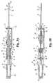
- FIG. 3A and FIG. 3Bare side cross-sectional views of the tissue biopsy apparatus depicted in FIGS. 1 and 2 , with the tissue cutting inner cannula shown in its retracted and extended positions.
- FIG. 4is a perspective view of a cover for the tissue biopsy apparatus as shown FIG. 1 .
- FIG. 5is an enlarged side cross-sectional view of the operating end of the tissue biopsy apparatus depicted in FIGS. 1 and 2 .
- FIG. 6is a side partial cross-sectional view of working end of a tissue biopsy apparatus in accordance with an alternative embodiment.
- FIG. 7is an end cross-sectional view of the apparatus depicted in FIG. 6 , taken along line 7 - 7 as viewed in the direction of the arrows.
- FIG. 8is an end cross-sectional view similar to FIG. 7 showing a modified configuration for a stiffening member.
- FIG. 8( a )is an end cross-sectional view similar to FIG. 7 showing a modified configuration for another stiffening member.
- FIG. 9is an enlarged side cross-sectional view of a fluid introduction port at the hub connecting the outer cannula to the handpiece for a tissue biopsy apparatus as depicted in FIG. 1 .
- FIG. 10is a schematic drawing of the hydraulic control system for the operation of the tissue biopsy apparatus shown in FIG. 1 .
- FIG. 11is a schematic drawing of a control system for an electric rotary motor for use with the apparatus of the present invention.
- FIG. 12is a top elevational view of a tissue biopsy apparatus according to a further embodiment of the present invention.
- FIG. 13is a side cross-sectional view of the biopsy apparatus shown in FIG. 12 , taken along line 13 - 13 as viewed in the direction of the arrows.
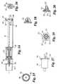
- FIG. 14is a side cross-sectional view of a motor assembly incorporated into the biopsy apparatus shown in FIG. 12 .
- FIG. 15is an end elevational view from the left end of the assembly depicted in FIG. 14 .
- FIG. 16is an end elevational view of the right end of the assembly depicted in FIG. 14 .
- FIG. 17is a top elevational view of a rotary motor assembly in accordance with one specific embodiment of the invention.
- FIG. 18is a side elevational view of a cannula hub for engagement with the assembly depicted in FIG. 14 .
- FIG. 19is a rear elevational view of the cannula hub shown in FIG. 18 .
- FIG. 20is a side cross-sectional view of the cannula hub shown in FIG. 18 .
- FIG. 21is a top perspective view of an upper housing component of the biopsy apparatus depicted in FIG. 12 .
- FIG. 22is an end cross-sectional view of the upper housing shown in FIG. 21 , taken along line 22 - 22 as viewed in the direction of the arrows.
- FIG. 23is a top perspective view of a lower housing for use with the biopsy apparatus shown in FIG. 12 .
- FIG. 24is a top elevational view of the lower housing shown in FIG. 23 .
- FIGS. 1-10A tissue biopsy apparatus 10 in accordance with one embodiment of the present invention is shown in FIGS.
- the apparatus 10includes a cutting element 11 mounted to a handpiece 12 .
- the cutting element 11is sized for introduction into a human body.
- the present inventionconcerns an apparatus for excising breast tissue samples.
- the cutting element 11 and the overall biopsy apparatus 10are configured for ease of use in this surgical environment.
- the biopsy apparatus 10is configured as a hand-held device.
- the same inventive principlescan be employed in a tissue biopsy apparatus that is used stereotatically in which the apparatus is mounted on a support fixture that is used to position the cuffing element 11 relative to the tissue to be sampled. Nevertheless, for the purposes of understanding the present invention, the tissue biopsy apparatus will be described as a hand-held device.
- the cutting element 11is configured as “tube-within-a-tube” cutting device. More specifically, the cutting element 11 includes an outer cannula 15 terminating in a tip 16 .
- the tipis a trocar tip that can be used to penetrate the patient's skin.
- the tip 16can simply operate as a closure for the open end of the cannula 15 . In this instance, a separate introducer would be required.
- the cutting element 11further includes an inner cannula 17 that fits concentrically within the outer lumen 27 ( FIG. 5 ) of the outer cannula 15 .
- both a rotary motor 20 ( FIG. 1 ) and a reciprocating motor 22drive the inner cannula 17 .
- Both motorsare supported within the handpiece 12 .
- the rotary motor 20 and reciprocating motor 22are configured for simultaneous operation to translate the inner cannula 17 axially within the outer cannula 15 , while rotating the inner cannula 17 about its longitudinal axis.
- the outer cannula 15defines a tissue-receiving opening 25 , which communicates with the outer lumen 27 .
- a pair of opposite longitudinal edges 26( FIGS. 1 and 2 ) define the tissue-receiving opening 25 .
- the outer cannula 15is open at its distal end 28 with the trocar tip 16 engaged therein.
- the trocar tip 16forms an engagement hub 30 that fits tightly within the distal end 28 of the outer cannula 15 .
- the hub 30can be secured by welding, press-fit, adhesive or other means suitable for a surgical biopsy instrument.
- the working end of the cutting element 11further includes a cutting board 31 that is at least snugly disposed within the outer lumen 27 at the distal end 28 of the outer cannula 15 .
- the cutting board 31is in direct contact with the engagement hub 30 of the trocar tip 16 .
- the cutting board 31can be permanently affixed within the outer cannula 15 and/or against the engagement hub 30 of the trocar tip.
- the inner cannula 17defines an inner lumen 34 that is hollow along the entire length of the cannula to provide for aspiration of the biopsy sample.
- the inner cannula 17terminates in a cutting edge 35 .
- the cutting edge 35is formed by an inwardly beveled surface 36 to provide a razor-sharp edge.
- the inwardly beveled surfacehelps eliminate the risk of catching the edge 35 on the tissue-receiving opening 25 of the outer cannula.
- the beveled surface 36helps avoid pinching the biopsy material between the inner and outer cannulas during a cutting stroke.
- both the outer cannula 15 and the inner cannula 17are formed of a surgical grade metal.
- the two cannulaeare formed of stainless steel.
- the cannulaecan be formed of Inconel, Titanium or other materials with similar magnetic characteristics.
- the trocar tip 16is most preferably formed of stainless steel honed to a sharp tip.
- the trocar tip 16can be suitably bonded to the outer cannula 15 , such as by welding or the use of an appropriate adhesive.
- the inner and outer cannulaecan be formed of a non-metallic material of appropriate strength and stiffness.
- the cutting board 31is formed of a material that is configured to reduce the friction between the cutting edge 35 of the inner cannula 17 and the cutting board 31 .
- the cutting edge 35necessarily bears against the cutting board 31 when the inner cannula 17 is at the end of its stroke while severing a tissue sample. Since the inner cannula is also rotating, the cutting edge necessarily bears directly against the cutting board 31 , particularly after the tissue sample has been cleanly severed. In prior devices, the impact-cutting surface has been formed of the same material as the cutting element. This leads to significant wear or erosion of the cutting edge. When numerous cutting cycles are to be performed, the constant wear on the cutting edge eventually renders it incapable of cleanly severing a tissue sample.
- the present inventioncontemplates forming the cutting board 31 of a material that reduces this frictional wear.
- the cutting board 31is formed of a material that is mechanically softer than the material of the cutting edge 35 .
- the cutting board 31cannot be so soft that the cutting edge 35 forms a pronounced circular groove in the cutting board, which significantly reduces the cutting efficiency of the inner cannula.
- the cutting board 31is formed of a plastic material, such as polycarbonate, ABS or DELRIN®.
- the rotary motor 20includes a motor housing 39 that is sized to reciprocate within the handpiece 12 .
- the housing 39defines a pilot port 40 that is connected to the hydraulic control system 150 (see FIG. 10 ) by appropriate tubing.
- the motor 20can be a number of hydraulically powered rotating components.
- the motor 20is an air motor driven by pressured air.
- the motor 20includes a vaned rotor 42 that is mounted on a hollow tubular axle 43 extending through the motor housing 39 .
- the axle 43is supported on bearings 44 at opposite ends of the housing so that the rotor 42 freely rotates within the motor housing 39 under pneumatic pressure.
- tubular axle 43is connected to the proximal end 37 of the inner cannula 17 by way of a coupler 46 .
- the ends of the two tubesare mounted within the coupler 46 and held in place by corresponding set screws 47 .
- the coupler 46is formed of a plastic material that provides a generally airtight seal around the joint between the inner cannula 17 and the tubular axle 43 . It is important that the coupler 46 provide a solid connection of the inner cannula 17 to the rotating components of the motor 20 so that the inner cannula 17 does not experience any torrential slip during the cutting operation.
- the inventionfurther contemplates an aspiration tube 50 that mates with the tubular axle 43 .
- the tissue aspiration path from the working end of the cutting element 11is along the inner lumen 34 of the inner cannula 17 , through the tubular axle 43 of the rotary motor 20 , and through the aspiration tube 50 to a tissue collection location in the form of a collection trap 55 .
- the aspiration tube 50In order to maintain the vacuum or aspiration pressure within this aspiration path, the aspiration tube 50 must be fluidly sealed against the tubular axle 43 .
- the motor housing 39defines a mounting hub 51 into which the aspiration tube 50 is engaged.
- the position of the aspiration tube 50is fixed by way of a set screw 52 passing through the mounting hub 51 .
- the joint between the aspiration tube 50 and the tubular axle 43allows relative rotational between the two components.
- the tubular axle 43rotates with the rotor 42 .
- the aspiration tube 50need not rotate for use with the biopsy apparatus of the present invention.
- the mounting hub 51cane include an arrangement of seal rings (not shown) at the joint between the aspiration tube 50 and the tubular axle 43 to further seal the aspiration system.
- the aspiration tube 50communicates with a collection trap 55 that is removably mounted to the handpiece 12 .
- the collection trap 55includes a pilot port 107 that is connected by appropriate tubing to the hydraulic control system 150 , as described in more detail herein.
- a vacuum or aspiration pressureis drawn through the pilot port 107 and the collection trap 55 .
- This vacuumthen draws a tissue sample excised at the working end of the cutting element 11 , all the way through the inner cannula 17 , tubular axle 43 and aspiration tube 50 until it is deposited within the trap. Details of the collection trap 55 will be discussed herein.
- the present inventioncontemplates an inner cannula 17 that performs its cutting operation by both rotary and reciprocating motion.
- the handpiece 12supports a reciprocating motor 22 .
- both motors 20 and 22are hydraulically powered, most preferably pneumatically. This feature allows the motors to be formed of plastic, since no electrical components are required.
- every component of the biopsy apparatus 10 in accordance with the present inventioncan be formed of a non-metallic material, most preferably a medical grade plastic.
- the biopsy apparatus 10is eminently compatible with surgical imaging systems that may be used during the biopsy procedure.
- the compatibility of the apparatus 10 with Magnetic Resonance Imaging (MRI)is important because MRI is currently the only non-invasive visualization modality capable of defining the margins of the tumor.
- MRIMagnetic Resonance Imaging
- the entire apparatuscan be disposable.
- the elimination of substantially all metal componentsreduces the overall weight of the handpiece 12 , making it very easily manipulated by the surgeon.
- the reciprocating motor 22includes a pneumatic cylinder 60 .
- the cylinder 60includes a pilot port 61 that connects the cylinder to the hydraulic control system 150 through appropriate tubing.
- the motor 22includes a piston 63 that reciprocates within the cylinder 60 in response to hydraulic fluid pressure provided at the pilot port 61 .
- the piston 63includes a central bore 64 for mounting the piston 63 to the aspiration tube 50 .
- the aspiration tube 50is press-fit within the bore 64 .
- the engagement between the aspiration tube 50 and the piston 63can be enhanced by use of a set screw (not shown) or an adhesive or epoxy. At any rate, it is essential that the aspiration tube 50 and piston 63 move together, since the motor 22 must eventually drive the inner cannula 17 axially within the outer cannula.
- the piston 63also reciprocates the rotary motor 20 , which is essentially mounted to the reciprocating aspiration conduit. This movement is depicted by comparing the position of the rotary motor 20 between FIG. 3A and FIG. 3B . More specifically, the motor 20 as well as the aspiration conduit, including the inner cannula 17 , moves within the handpiece 12 .
- the handpiece housing 70is provided with openings 73 ( FIG. 3B ) at its opposite ends for slidably supporting the aspiration tube 50 and inner cannula 17 . Since the distal housing 70 is preferably formed of a plastic material, no thrust bearings or rotary bearings are necessary to accommodate low friction axial movement of the cannula through the housing openings 73 .
- the biopsy apparatus 10includes a handpiece 12 that carries all of the operating components and supports the outer and inner cannulas.
- the handpiece 12includes a distal housing 70 within which is disposed the rotary motor 20 .
- the distal end 71 of the housing 70is configured into a fitting 72 .
- This fitting 72engages a mating flange 77 on an outer cannula hub 75 .
- the hub 75supports the outer cannula 15 within an engagement bore 76 (see FIG. 3B ).
- the engagement between the outer cannula hub 75 and the distal end 71 of the housing 70need not be airtight.
- the mating components of the fitting between the two partsneed not be capable of generating a fluid-tight seal.
- the engagement between the hub 75 and the housing 70 for supporting the outer cannula 15provides a leak path through the outer lumen 27 to the atmosphere.
- providing aspiration through the inner lumen 34 of the inner cutting cannula 17will draw tissue through the inner lumen. As the tissue advances farther along the lumen, in some instances a vacuum can be created behind the advancing tissue.
- the tissuewill stop advancing along the length of the inner lumen because the vacuum behind the tissue sample equals the vacuum in front of the tissue sample that is attempting to draw the sample to the collection trap 55 .
- the leak path through the outer lumen 27allows atmospheric air to fall in behind the tissue sample when the inner cutter is retracted from the cutting board.
- the atmospheric airhelps to relieve the vacuum behind the advancing tissue and aids in drawing the tissue down the length of the aspiration channel to the collection trap 55 .
- the atmospheric air leak pathis not essential.
- the fitting 72 and the mating flange 77can be engaged by simple twisting motion, most preferably via Luer-type fittings.
- the cannula hub 75is mounted on the handpiece 12 , thereby supporting the outer cannula 15 .
- the handpiececan then be used to project the outer cannula into the body adjacent the sample site.
- the outer cannula 15can be used to introduce an anesthetic.
- the outer cannulacan be used to guide a radio-opaque marker to mark the location the removed material.
- the housingdefines an inner cavity 79 that is open through an access opening 81 .
- the access opening 81is preferably provided to facilitate assembly of the tissue biopsy apparatus 10 .
- the distal end 71 of the housing 70can be provided with a pair of distal braces 80 that add stiffness to the distal end 71 while the apparatus is in use.
- the braces 80allow the distal housing 70 to be formed as a thin-walled plastic housing. Similar braces can be provided at the opposite end of the distal housing as necessary to add stiffness to the housing.
- the distal housingis configured to support the reciprocating motor 22 and in particular the cylinder 60 .
- the proximal end 83 of the distal housing 70defines a pressure fitting 84 .
- this pressure fitting 84provides a tight leak-proof engagement between the distal end 88 of the cylinder 60 and the proximal end 83 of the housing.
- the pressure fitting 84forms a spring cavity 85 within which a portion of the return spring 66 rests.
- the pressure fitting 84defines distal piston stop 86 .
- the piston 63contacts these stops at the end of its stroke. The location of the piston stop 86 is calibrated to allow the cutting edge 35 to contact the cutting board 31 at the working end of the cutting element 11 to allow the cutting edge to cleanly sever the biopsy tissue.
- the cylinder 60is initially provided in the form of an open-ended cup.
- the open endcorresponding to distal end 88 , fastens to the pressure fitting 84 .
- the pressure fittingcan include a threaded engagement, a press-fit or an adhesive arrangement.
- the cylinder cupthus includes a closed proximal end 89 .
- This proximal enddefines the pilot port 61 , as well as a central opening 62 ( FIG. 3B ) through which the aspiration tube 50 extends.
- the proximal end 89 of the cylinder 60is configured to provide a substantially airtight seal against the aspiration tube 50 even as it reciprocates within the cylinder due to movement of the piston 63 .
- the proximal end 89 of the cylinder 60defines a proximal piston stop 90 , which can either be adjacent the outer cylinder walls or at the center portion of the proximal end. This proximal piston stop 90 limits the reverse travel of the piston 63 under action of the return spring 66 when pressure within the cylinder has been reduced.
- the collection trap 55is mounted to the handpiece 12 by way of a support housing 93 .
- the handpiece 12can be limited to the previously described components.
- the collection trap 55can be situated separate and apart from the handpiece, preferably close to the source of vacuum or aspiration pressure.
- the proximal end of the aspiration tube 50would be connected to the collection trap by a length of tubing.
- the aspiration tube 50would reciprocate away from and toward the proximal end of the cylinder 60 , so that it is preferable that the handpiece includes a cover configured to conceal the reciprocating end of the aspiration tube.
- the collection trap 55is removably mounted to the handpiece 12 .
- a pair of longitudinally extending arms 94that define an access opening 95 therebetween, forms the support housing 93 .
- the support housing 93includes a distal end fitting 96 that engages the proximal end 89 of cylinder 60 .
- a variety of engagementsare contemplated, preferably in which the connection between the two components is generally airtight.
- the proximal end 97 of the support housing 93forms a cylindrical mounting hub 98 .
- the mounting hub 98surrounds a proximal end of the collection trap 55 .
- the hubforms a bayonet-type mounting groove 99 that receives pins 103 attached to the housing 102 of the trap 55 .
- a pair of diametrically opposite wings 104can be provided on the housing 102 to facilitate the twisting motion needed to engage the bayonet mount between the collection trap 55 and the support housing 93 .
- the preferred embodimentcontemplates a bayonet mount, other arrangements for removably connecting the collection trap 55 to the support housing 93 are contemplated. To be consistent with one of the features of the invention, it is preferable that this engagement mechanism be capable of being formed in plastic.
- the support housing 93is provided with an aspiration passageway 100 that spans between the proximal and distal ends of the housing. Since the aspiration tube 50 reciprocates, it preferably does not extend into the collection trap 55 . As excised tissue is drawn into the trap 55 , a reciprocating aspiration tube 50 can contact the biopsy material retained within the trap. This movement of the tube can force tissue into the end of the tube, clogging the tube. Moreover, the reciprocation of the aspiration tube can compress tissue into the end of the trap, thereby halting the aspiration function.
- the collection trap 55includes a housing 102 , as previously explained.
- the housingforms a pilot port 107 , which is connectable to a vacuum generator.
- appropriate tubing to the hydraulic control system 150connects the pilot port 107 .
- the trap 55includes a filter element 110 mounted within the trap.
- the filter elementis a mesh filter than allows ready passage of air, blood and other fluids, while retaining excised biopsy tissue samples, and even morcellized tissue.
- the filter element 110is preferably constructed so that vacuum or aspiration pressure can be drawn not only at the bottom end of the filter element, but also circumferentially around at least a proximal portion of the element 110 . In this way, even as material is drawn toward the proximal end of the filter, a vacuum can still be drawn through other portions of the filter, thereby maintaining the aspiration circuit.
- the handpiece 12can include individual covers for closing the access opening 81 in the distal housing 70 and the access openings 95 in the support housing 93 . Those covers can support tubing for engagement with the pilot ports 40 and 61 . Alternatively and most preferably, a single cover 13 as depicted in FIG. 4 , is provided for completely enclosing the entire handpiece.
- the distal end 71 of the housing 70can define a number of engagement notches 115 equally spaced around the perimeter of the distal end.
- the handpiece cover 13can then include a like number of equally distributed tangs 117 projecting inwardly from the inner surface from the 118 . These tangs are adapted to snap into the engagement notches 115 to hold the cover 113 in position over the handpiece 12 .
- the covercan be attached by sliding axially over the handpiece 12 .
- the cover 13can include fittings for fluid engagement with the two pilot ports 40 and 61 .
- the covercan be formed with openings for insertion of engagement tubing to mate with the respective pilot ports to provide hydraulic fluid to the rotary motor 20 and the reciprocating motor 22 .
- the cover 13extends from the distal end 71 of the distal housing 70 to the proximal end 97 of the support housing 93 .
- the covercan thus terminate short of the bayonet mounting feature between the support housing and the collection trap 55 .
- the proximal end 97 of the support housing 93can be configured to include a similar array of engagement notches with a corresponding array of mating tangs formed at the proximal end of the cover 13 .
- the biopsy apparatus 10 of the present inventionprovides a complete “closed” tissue excision and recovery system.
- the apparatus 10is fluid tight so that no bodily fluids can escape. Biopsy procedures with many prior devices involves significant blood splatter due to the nature in which the tissue samples are extracted and recovered.
- the biopsy apparatus 10provides a closed path from the tissue receiving opening 25 to the collection trap 55 , while still maintaining the highly efficient reciprocating and rotating cutting operation.
- an outer cannula 125includes a tissue-receiving opening 126 .
- the openingis formed by opposite longitudinal edges 127 .
- a number of teeth 129are formed at each longitudinal edge 127 .
- the teethare proximally facing—i.e., away from the cutting board 31 (not shown) at the distal end of the outer cannula. With this orientation, the teeth 129 help prevent forward motion of tissue drawn into the opening 126 as the inner cannula 17 moves forward toward the cutting board.
- the cutting edgenot only starts to sever the tissue, it also pushes tissue in front of the inner cannula.
- the ultimate length of the biopsy sample retrieved with the cutis smaller than the amount of tissue drawn into the tissue-receiving opening of the outer cannula.
- the tissue sample removed through the inner cannula 17is substantially the same length as the tissue-receiving opening 126 .
- each of the teeth 129tends to hold the tissue in place as the cuffing edge 35 severs the tissue adjacent the outer cannula wall.
- each “bite”is substantially as large as possible so that a large tissue mass can be removed with much fewer “bites” and in a shorter period of time.
- the teethcan also cut into the tissue to prevent it from retracting out of the opening as the inner cutting cannula 17 advances.
- the outer cannula 125 depicted in FIG. 6can also incorporate a stiffening element 131 opposite the tissue-receiving opening 126 .
- the stiffening element 131adds bending stiffness to the outer cannula 125 at the distal end in order to maintain the longitudinal integrity of the outer cannula 125 as it is advanced into a tissue mass.
- the working end of the cutting deviceis compromised as it bends slightly upward or downward as the outer cannula passes into the body. This bending can either close or expand the tissue-receiving opening, which leads to difficulties in excising and retrieving a tissue sample.
- the cutting mechanism of the present inventionrelies upon full, flush contact between the cutting edge of the inner cannula 17 and the cutting board 31 . If the end of the outer cannula 125 is slightly askew, this contact cannot be maintained, resulting in an incomplete slice of the tissue sample.
- the stiffening element 131in one embodiment is a crimp extending longitudinally in the outer wall of the cannula substantially coincident with the tissue-receiving opening 126 .
- the outer cannula 125 ′ depicted in FIG. 8shows two additional versions of a stiffening element. In both cases, a bead of stiffening material is affixed to the outer cannula. Thus in one specific embodiment, a bead 131 ′ is adhered to the inner wall of the outer cannula. In a second specific embodiment, a bead 131 ′′ is affixed to the outside of the outer cannula.
- the beadscan be formed of a like material with the outer cannula, and in both cases, the beads provide the requisite additional bending stiffness.
- Another version of a stiffening elementis shown if FIG. 8( a ). In this case, a layer 131 ′′′ of additional stainless steel is bonded to the outer wall of the outer cannula 125 ′′.
- a further feature that can be integrated into the outer cannula 125is the dimple 135 .
- One problem frequently experienced by tube-within-a-tube cuttersis that the inner reciprocating cutter blade contacts or catches on the outer cannula at the distal edge of the tissue-receiving opening.
- the dimple 135urges the inner cannula 17 away from the tissue-receiving opening 126 . In this way, the dimple prevents the cutting edge of the inner cannula 17 from catching on the outer cannula as it traverses the tissue-receiving opening.
- the dimple 135is in the form of a slight crimp in the outer cannula 125 .
- the dimple 135can be formed by a protrusion affixed or adhered to the inner surface of the outer cannula.
- the dimple 135is situated immediately proximal to the tissue-receiving opening to help maintain the distance between the cutting edge and the tissue-receiving opening.
- the outer cannula 15is supported by a hub 75 mounted to the distal end of the handpiece.
- the outer cannula hub 140provides a mean for introducing fluids into the outer lumen 27 of the outer cannula.
- the hub 140includes an engagement bore 141 within which the outer cannula 15 is engaged.
- the hubalso defines a flange 142 configured for mating with the fitting 72 at the distal end 71 of the housing 70 .
- the outer cannula hub 140is similar to the hub 75 described above. With this embodiment, however, an irrigation fitting 145 is provided.
- the fittingdefines an irrigation lumen 146 that communicates with the engagement bore 141 .
- this irrigation lumenis in fluid communication with the outer lumen 27 of the outer cannula 15 .
- the irrigation fitting 145can be configured for engagement with a fluid-providing device, such as a syringe.
- the hub 140thus provides a mechanism for introducing specific fluids to the biopsy site. In certain procedures, it may be necessary to introduce additional anesthetic to the sampling site, which can be readily accommodated by the irrigation fitting 145 .
- the preferred embodiment of the tissue biopsy apparatus 10relies upon hydraulics or pneumatics for the cutting action.
- the apparatusincludes a hydraulic rotary motor 20 and a hydraulic reciprocating motor 22 .
- the apparatus 10can be adapted for taking a single biopsy slice, the preferred use is to completely remove a tissue mass through successive cutting slices.
- the cutting element 11is positioned directly beneath a tissue mass, while an imaging device is disposed above the mass.
- the imaging devicesuch as an ultra-sound imager, provides a real-time view of the tissue mass as the tissue biopsy apparatus 10 operates to successively remove slices of the mass.
- Tissueis continuously being drawn into the cutting element 11 by the aspiration pressure or vacuum drawn through the inner cannula 17 . Successive reciprocation of the inner cannula 17 removes large slices of the mass until it is completely eliminated.
- the present inventioncontemplates a hydraulic control system 150 , as illustrated in the diagram of FIG. 10 .
- the bulk of the control systemis housed within a central console.
- the consoleis connected to a pressurized fluid source 152 .
- the fluid sourceprovides a regulated supply of filtered air to the control system 150 .
- pressurized fluid from the sourceas provided at the several locations 152 throughout the control system. More specifically, pressurized fluid is provided to five valves that form the basis of the control system.
- pressurized fluid 152passes through a pressure regulator 154 and gauge 155 .
- the gauge 155is preferably mounted on the console for viewing by the surgeon or medical technician.
- the pressure regulator 154is manually adjustable to control the pressurized fluid provided from the source 152 to the two-position hydraulic valve 158 .
- the valve 158can be shifted between a flow path 158 a and a flow path 158 b .
- a return spring 159biases the hydraulic valve to its normal position 158 a.
- valve 158connects cylinder pressure line 161 to the fluid source 152 .
- This pressure line 161passes through an adjustable flow control valve 162 that can be used to adjust the fluid flow rate through the pressure line 161 .
- the adjustable flow control valve 162can be mounted on a console for manipulation during the surgical procedure.
- the pressure line 161is connected to the pilot port 61 of the reciprocating motor 22 .
- fluid pressureis provided to the cylinder 60 to drive the piston 63 against the biasing force of the return spring 66 .
- the initial position of the hydraulic valve 158is such that the reciprocating motor and inner cannula are driven toward the distal end of the cutting element.
- the inner cannula 17covers the tissue-receiving opening 25 of the outer cannula 15 . With the inner cannula so positioned, the outer cannula can be introduced into the patient without risk of tissue filling the tissue-receiving opening 25 prematurely.
- Pressurized fluid along cylinder pressure 161is also fed to a pressure switch 165 .
- the pressure switchhas two positions providing flow paths 165 a and 165 b .
- an adjustable return spring 166biases this switch to its normal position at which fluid from the pressure source 152 terminates within the valve.
- the pressure switch 165moves to its flow path 165 b in which the fluid source 152 is hydraulically connected to the pressure input line 168 .
- This pressure input line 168feeds an oscillating hydraulic valve 170 . It is this valve that principally operates to oscillate the reciprocating motor 22 by alternately pressurizing and releasing the two-position hydraulic valve 158 .
- the pressure switch 165is calibrated to sense an increase in pressure within the cylinder pressure line 161 or in the reciprocating motor cylinder 60 that occurs when the piston 66 has reached the end of its stroke. More specifically, the piston reaches the end of its stroke when the inner cannula 17 contacts the cutting board 31 . At this point, the hydraulic pressure behind the piston increases, which increase is sensed by the pressure valve 165 to stroke the valve to the flow path 165 b.
- the oscillating hydraulic valve 170has two positions providing flow paths 170 a and 170 b .
- input line 179is fed to oscillating pressure output line 172 .
- the input line 179is fed to a blocked line 171 .
- the oscillating valve 170opens flow path 170 a which completes a fluid circuit along output line 172 to the input of the hydraulic valve 158 .
- Fluid pressure to output line 172occurs only when there is fluid pressure within input line 179 .
- This input lineis fed by valve 176 , which is operated by foot pedal 175 .
- the valve 176is biased by a return spring 177 to the initial position of flow path 176 a .
- the valve 176is moved against the force of the spring to flow path 176 b .
- pressurized fluid from the source 152is connected to the foot pedal input line 179 .
- pressurized fluidthen flows through input line 179 to output line 172 and ultimately to the hydraulic valve 158 .
- the fluid pressure in the output line 172shifts the valve 158 to the flow path 158 b .
- the fluid pressure behind the piston 63is relieved so that the return spring 66 forces the piston toward the proximal end. More specifically, the return spring retracts the inner cannula 17 from the tissue cutting opening 25 .
- the relief of the fluid pressure in line 161also causes the pressure switch 165 to return to its initial neutral position of flow path 165 a , due to the action of the return spring 166 .
- the pressure input line 168is no longer connected to the fluid source 152 , so no pressurized fluid is provided to the oscillating hydraulic valve 170 . Since this valve is not spring biased to any particular state, its position does not necessarily change, except under conditions described herein.
- the biasing spring 177forces the valve 176 from its flow path 176 b to its normal initial flow path 176 a .
- the foot pedal input line 179is no longer connected to the fluid source 152 .
- the oscillating valve 170is at flow path 170 a , the fluid pressure through output line 172 is eliminated.
- hydraulic valve 158is shifted to its original flow path 158 a by operation of the return spring 159 .
- the cylinder pressure line 161is again connected to the fluid source 152 , which causes the reciprocating motor 22 to extend the inner cannula 17 to its position blocking the tissue-receiving opening 25 .
- the hydraulic control system 150starts and finishes the tissue biopsy apparatus 10 with the tissue-receiving opening closed. It is important to have the opening closed once the procedure is complete so that no additional tissue may be trapped or pinched within the cutting element 11 as the apparatus is removed from the patient.
- the system 150also controls the operation of the rotary motor 20 .
- the motor 20is an air motor.
- This air motoris controlled by another hydraulic valve 182 .
- the initial position of the valveprovides a flow path 182 a in which the fluid source 152 is connected to blocked line 183 .
- the hydraulic valve 182is pressurized, it moves to flow path 182 b in which the fluid source 152 is connected to the pilot port 140 of the air motor. In this position, pressurized fluid continuously drives the air motor 20 , thereby rotating the inner cannula 17 .
- a muffler Mcan be provided on the air motor to reduce noise.
- the rotary motor hydraulic valve 182is controlled by fluid pressure on pressure activation line 180 .
- This activation line 180branches from the foot pedal input line 179 and is connected to the foot pedal switch 176 .
- the switchmoves to its flow path 176 b .
- the pressure activation line 180is connected to the fluid source 152 so fluid pressure is provided directly to the rotary motor hydraulic valve 182 .
- the valve 182includes a biasing spring 184 that must be overcome by the fluid pressure at the input to the valve.
- the motor 20since the fluid control for the rotary motor 20 is not fed through the oscillating hydraulic valve 170 , the motor operates continuously as long as the foot pedal 175 is depressed. In addition, it should also be apparent that the speed of the rotary motor 20 is not adjustable in the illustrated embodiment. Since the motor 20 is connected directly to the fluid source 152 , which is preferably regulated at a fixed pressure, the air motor actually operates at one speed. On the other hand, as discussed above, the reciprocating motor 22 is supplied through a pressure regulator 154 and a flow control valve 162 . Thus, the speed of reciprocation of the cutting blade 35 is subject to control by the surgeon or medical technician.
- the reciprocation of the cutting element 11can be a function of the tissue being sampled, the size of the tissue biopsy sample to be taken, and other factors specific to the particular patient. These same factors generally do not affect the slicing characteristic of the cutting edge 35 achieved by rotating the inner cannula.
- the hydraulic control system 150also regulates the aspiration pressure or vacuum applied through the aspiration conduit, which includes the inner cannula 17 .
- the pressure activation line 180branches to feed an aspiration valve 185 .
- the valveis movable from its initial flow path 185 a to a second flow path 185 b .
- the fluid source 152is connected to a blocked line 186 .
- the venturi element 190is connected to the fluid source. This venturi element thus generates a vacuum in a vacuum control line 193 and in aspiration line 191 .
- the venturi element 190can include a muffler M to reduce noise within the handpiece.
- the vacuum drawn on control line 193operates on vacuum switch 194 .
- a variable biasing spring 195initially maintains the vacuum switch 194 at its flow path 194 a .
- the vacuum input line 196is not connected to any other line.
- the valvemoves to flow path 194 b .
- the vacuum input line 196is connected to pressure line 192 .
- the vacuum switch 194operates in the form of a “go-nogo” switch—in other words, when the aspiration vacuum reaches a predetermined operating threshold, the vacuum switch is activated.
- the vacuum switch 184is initially activated, it remains activated as long as the foot pedal is depressed.
- vacuum input line 196is continuously connected to pressure line 192 as long as the foot pedal 175 is depressed.
- the fluid pressure in line 192is determined by the state of valve 158 .
- the pressure line 192is dead.
- pressure line 192is connected to the regulated fluid source. Pressurized fluid then flows from pressure line 192 , through vacuum switch flow path 194 b , through vacuum input line 196 to the left side of oscillating valve 170 , causing the valve to stroke to flow path 170 b .
- valve 158When the oscillating valve 170 is in this flow path, output line 172 is dead, which allows valve 158 to move to its flow path 158 a under the effect of the return spring 159 . In this state, valve 158 allows pressurized fluid to again flow to the reciprocating motor 22 causing it to move through the next cuffing stroke.
- pressurized fluidpasses from line 192 , through vacuum input line 196 , and through an adjustable flow control valve 197 to a second input for the oscillating hydraulic valve 170 .
- Pressure on the vacuum input line 196shifts the oscillating valve 170 to its second position for flow path 170 b .
- pressurized fluid passing through the foot pedal valve 176terminates within valve 170 .
- the pressure in output line 172drops which allows the hydraulic valve 158 shift back to its original position 158 a under operation of the return spring 159 .
- fluid pressureis again supplied to the reciprocating motor 22 to cause the piston 66 to move through its cutting stroke.
- the oscillating valve 170is influenced by fluid pressure on lines 168 and 196 , and that these lines will not be fully pressurized at the same time.
- pressure from source 152is automatically supplied to reciprocating motor 22 and pressure valve 165 , causing the valve to move to flow path 165 b .
- line 168is pressurized which shifts oscillating valve 170 to the left to state 170 a .
- the oscillating valvewill remain in that state until line 196 is pressurized, regardless of the position of pressure switch 165 .
- the fluid pressure on line 196does not increase to operating levels until the foot pedal 175 has been depressed and the aspiration circuit has reached its operating vacuum.
- the vacuum switch 194can be calibrated to sense fine changes in vacuum.
- the completion of this return strokecan be determined by the state of the vacuum switch 194 .
- the vacuum switch 194can operate as an indicator that a tissue sample has been drawn completely through the aspiration conduit into the collection trap 55 . More specifically, when the vacuum sensed by vacuum switch 194 has one value when the inner cannula is open to atmospheric pressure. This vacuum pressure changes when a tissue sample is drawn into the inner cannula 17 . The vacuum pressure changes again when the tissue is dislodged so that the inner cannula is again open to atmospheric pressure. At this point, the inner cannula 17 is clear and free to resume a cutting stroke to excise another tissue sample.
- the vacuum switch 194can stroke to its flow path 194 b to provide fluid pressure to the left side of the oscillating valve 170 , causing the valve to stroke to flow path 170 b.
- the hydraulic control system 150provides a complete system for continuously reciprocating the axial motor 22 .
- the systemprovides constant continuous pressure to both the rotary motor 20 and the aspiration line 191 , so long as the foot pedal 175 is depressed. Once the foot pedal is released, fluid pressure in activation line 180 drops which causes the air motor control valve 182 and the aspiration control valve 185 to shift to their original or normal positions in which fluid pressure is terminated to those respective components.
- pressureis maintained to the reciprocating motor 22 because the motor is fed through valve 158 , which is connected directly to the fluid source 152 .
- the hydraulic control system 150 in the illustrated embodimentincorporates five controllable elements.
- the fluid pressure provided to activate the reciprocating motor 22is controlled through the regulator 154 .
- the fluid flow rate to the piston 66is controlled via the adjustable control valve 162 .
- the pressure at which the pressure switch 165 is activatedis determined by an adjustable return spring 166 .
- the aspiration pressure vacuum at which the vacuum switch 194 is activatedis controlled by an adjustable return spring 195 .
- the adjustable flow control valve 197controls the fluid flow from the vacuum switch 194 to the oscillating hydraulic valve 170 .
- Each of these adjustable elementscontrols the rate and duration of oscillation of the reciprocating motor 22 .
- the pressure switch 165essentially operates as an “end of stroke” indicators. In other words, when the inner cannula 17 reaches the end of its forward or cutting stroke, it contacts the cutting board 31 . When it contacts the cutting board, the pressure in the cylinder pressure line 161 changes dramatically. It is this change that causes the pressure switch 165 to change states. This state change causes the oscillating valve 170 to shift valve 158 to terminate fluid pressure to the motor 22 , causing it to stop its cutting stroke and commence its return stroke.
- the use of a hydraulically controlled inner cutting cannulaprovides significant advantages over prior tissue cuffing devices.
- the use of hydraulicsallows most of the operating components to be formed of inexpensive and light-weight non-metallic materials, such as medical-grade plastics.
- the hydraulic system of the present inventioneliminates the need for electrical components, which means that electrical insulation is unnecessary to protect the patient.
- the hydraulically controlled reciprocation of the inner cutting cannulaprovides a cleaner and better-controlled cut of biopsy tissue. Since the reciprocating motor 22 is fed from a substantially constant source of pressurized fluid, the pressure behind the motor piston 63 remains substantially constant throughout the cutting stroke. This substantially constant pressure allows the inner cutting cannula to advance through the biopsy tissue at a rate determined by the tissue itself.
- the rotary motor 20can consist of an electric motor, rather than a pneumatic motor.
- the pressure activation line 180can be fed to an on-off pressure switch 198 that is governed by an adjustable bias spring 199 .
- the switch 198establishes a connection between an electric reciprocating motor 20 and a battery pack 200 .
- the battery pack 200is mounted within the handpiece 12 , but can instead be wired to an external battery contained within the console.
- the tissue biopsy apparatus 10 depicted in FIG. 1has an overall length of under sixteen inches (16′′) and an outer diameter less than one and one quarter inches (1.25′′).
- the outer cannula and therefore the cutting element 11have a length measured from the handpiece 12 of approximately five inches (5′′).
- the outer cannulapreferably has a nominal outer diameter of 0.148′′ and a nominal inner diameter of 0.136′′.
- the inner cannulamost preferably has a nominal outer diameter of 0.126′′ so that it can reciprocate freely within the outer cannula without catching on the tissue cutting opening.
- the inner cannulahas a nominal wall thickness of 0.010′′, which yields a nominal inner lumen diameter of about 0.106.′′
- the length of the tissue-receiving openingdetermines the length of biopsy sample extracted per each oscillation of the reciprocating motor 22 .
- the openinghas a length of about 0.7′′, which means that a 0.7′′ long tissue sample can be extracted with each cutting cycle.
- the collection trapcan have a length of about 2.5′′ and a diameter of about 0.05′′.
- the interior volume of the collection trapcan vary depending upon the size of each biopsy slug and the amount of material to be collected.
- the filter disposed within the collection trap 55manufactured by Performance Systematix, Inc. of Callondoni, Mich.
- the cutting stroke for the inner cannulais about 0.905′′.
- the return spring 66 within the reciprocating motor 22is preferably a conical spring to reduce the compressed height of the spring, thereby allow a reduction in the overall length of the hydraulic cylinder 60 .
- the return spring 66can be calibrated so that the return stroke occurs in less than about 0.3 seconds.
- the inwardly beveled surface 36 of cutting edge 35is oriented at an approximately 30° angle.
- the aspiration pressure vacuumis nominally set at 27 in.Hg. during the cutting stroke.
- the vacuum pressureis reduced to 25 in.Hg. this aspiration pressure normally allows aspiration of a tissue sample in less than about 1 second and in most cases in about 0.3 second.
- the hydraulic control system 150preferably is calibrated so that the inner cannula dwells at its retracted position for about 0.3 seconds to allow complete aspiration of the tissue sample. Adjusting the return spring 195 of the vacuum switch 194 can control this dwell rate.
- the inner cannula 17can advance through the cutting stroke in about two seconds. This stroke speed can be accomplished with a regulated pressure at source 152 of about 20 p.s.i. When the inner cannula reaches the end of its cutting stroke, the pressure can increase at about five p.s.i. per second.
- the return spring 166 of the pressure switch 165is set so that the end of cutting stroke is sensed within about 0.5 seconds.
- a tissue biopsy apparatus 300is configured as depicted in FIGS. 12-24 .
- the apparatus 300includes a cutting element 302 mounted to a user manipulable handpiece 305 .
- the handpieceincludes an upper housing 310 , and a lower housing 311 (see FIG. 13 ).
- a cannula hub 312is mounted to the handpiece 305 to support the outer cannula 303 of the cutting element 302 in a fashion similar to that described above.
- the biopsy apparatus 300further includes a filter canister 315 that is removably mounted to the handpiece 305 , again in a manner similar to that described above.
- the biopsy apparatus 300incorporates a secondary lumen 320 that engages the cannula hub 312 .
- the secondary lumen 320can be used to supply a quantity of irrigation fluid or a measured quantity of air to the cutting element, in a manner described below.
- the upper housing 310preferably includes a channel 322 defined along its entire length. The channel is configured to receive the secondary lumen 320 therein with the lumen recessed within the housing so as to not interfere with the ability of the surgeon to comfortably grip the biopsy apparatus 300 .
- the biopsy apparatus 300includes a reciprocating motor assembly 330 and a rotary motor assembly motor 332 .
- the reciprocating motor assembly 330includes a housing 340 that is contained within the upper and lower housing 310 , 311 that define the handpiece 305 .
- the reciprocating motor 334is similar to the motor described above.
- the motorincludes a tube fitting 335 for receiving a hollow tube 337 (see FIG. 13 ).
- the tube 337is connected to the hydraulic control system 150 depicted in FIG. 10 to provide an alternating supply of pressurized air to the reciprocating motor 334 in a manner described above.
- the housing 340includes a pair of opposite rails 341 , which serve as guides for reciprocation of the rotary motor 332 .
- the rotary motor 332includes opposite anti-rotation wings 355 that ride along the rails 341 as the motor 332 is reciprocated, and at the same time resist rotation of the rotary motor 332 during its operation.
- the rotary motor 332further includes a tube fitting 357 that is arranged to engage a hollow tube 358 (see FIG. 13 ) which, like the tube 337 , provides a connection to the hydraulic control system 150 .
- the housing 340forms a Luer fitting 345 at its distal end 342 , as illustrated in FIG. 16 .
- the Luerfittingincludes a circumferential recess 347 and a number of spaced flanges 348 . Preferably, four such flanges spaced at 90° intervals are incorporated into the Luer fitting 345 .
- the recess 347defines an enlarged gap 349 between one pair of flanges.
- a number of retention dimples 350are defined at the base of the circumferential recess 347 , as depicted in FIGS. 14 and 15 .
- the Luer fitting 345is configured to mate with the cannula hub 312 .
- the cannula hub 312includes a number of Luer wings 370 corresponding in number to the plurality of flanges 348 .
- Each of the wings 370is configured to fit within the recess the 347 between flanges 348 .
- One of the wings 370includes an enlargement 371 that prevents the cannula 312 from being improperly oriented, or more specifically assures a predetermined orientation of the tissue receiving opening of the cannula 312 .
- the enlargement 371is preferably configured to fit within the enlarged gap 349 of the Luer fitting 345 to insure an upward orientation of the cutting element 302 , as depicted in FIGS. 12 and 13 .
- the bottom surface of the cannula hub 312defines a number of protuberances 372 .
- Each of the protuberancesis sized to fit within one of the retention dimples 350 of the Luer fitting 345 .
- each of the protuberances 372engages within a corresponding dimples to hold the cannula hub 312 in place.
- the cannula hub 312includes a central bore 376 extending through the hub. One portion 377 of the bore is sized to tightly receive the outer cannula 303 of the cutting element 302 as described with respect to outer cannula 15 . Preferably, the outer cannula 303 is engaged in a substantially fluid tight fit.
- the hub 312is configured for removable engagement with the Luer fitting 345 of the handpiece 305 so the entire handpiece can be removed from the hub 312 while the outer cannula 303 is still in place within the patient.
- the inner cutting element 304is withdrawn from the lumen 306 of the outer cannula, since the inner cutting element is connected to the reciprocating motor assembly 334 as described above.
- the cannula hub 312 and outer cannula 302remain at the surgical site to permit introduction of medical treatments or other instruments through the bore 376 and lumen 306 .
- a local anaesthetic, drug or treatment materialsuch as a radioactive pellet, can be introduced in this manner, before, during or after the biopsy procedure.
- other surgical instrumentssuch as a visualization scope, can be guided to the biopsy site through the hub 312 and cannula 302 .
- the cannula hub 312also includes a tube fitting 375 .
- the Tube fitting 375mates with the secondary lumen 320 that traverses the outer length of the handpiece 305 .
- the fitting 375can be of any suitable configuration for providing a fluid-tight engagement between the fitting and a tube.
- the reciprocating motor assembly motor housing 340also includes a proximal end 360 that defines a mounting hub 361 .
- the mounting hubis similar to the hub 98 described above, and is particularly configured to engage the filter canister 315 .
- the hub and canister interfacecan be in the form of a bayonet mount to provide a fluid tight quick release engagement.
- the proximal end of the housing 340defines a circumferential flange 363 that is sealed against the ends of the upper and lower housings 310 , 311 of the handpiece 305 .
- a pair of tube cutouts 365are formed at the perimeter of the flange 363 to provide a passageway for the hydraulic tubes 337 - and 358 supplying pressurized fluid to the reciprocating and rotary motors.
- the upper and lower housings 310 and 311can be configured as shown in FIGS. 21-24 .
- the upper housing 310includes an interior channel 380 that passes substantially along the entire length of the interior of the upper housing 310 . This interior channel is aligned with one of the tube cutouts 365 in the flange 363 of the housing 340 . This interior channel can provide a pathway for the tube 358 feeding pressurized fluid to the rotary motor assembly 332 .
- the upper housing 310further defines a number of interior support walls 382 . These walls project into the interior space and serve as a bulkhead for supporting the various working components of the handpiece 305 .
- the lower housing 311includes a number of interior support walls 385 .
- the lower housing 311can include a longitudinal support rib 387 that preferably is arranged to support the reciprocating motor 334 .
- At least some of the interior support wall 385 of the lower housing 311can define tube cutouts 389 to receive the tube 337 feeding pressurized fluid to the reciprocating motor 334 .
- the lower housing 311can include a number of mounting holes 395 . These mounting holes can be arranged to permit mounting of the tissue biopsy apparatus 300 on an existing biopsy table.
- the biopsy apparatus 300can be mounted on a slideable carriage that can be separately driven to project the cutting element 302 into the patient. Support beds of this type are well known and the mounting feature 395 of the handpiece 305 can be specifically configured to accommodate any particular support bed.
- the upper and lower housings 310 , 311include interlocking mating edges 397 , 398 , respectively.
- the edgesinclude press-fit male/female interfaces.
- the engagementcan simply be a removable snap-fit, while in other embodiments, the engagement can be permanent, such as by the use of an adhesive.
- the tissue biopsy apparatus 300can be connected to the hydraulic control system 150 described above. Each of the components can operate in a manner similar to that described above.
- the cannula hub 312provides a fluid interface for the external secondary lumen 320 which can be used to introduce a fluid, such as a saline solution, to the surgical site.
- a saline flushcan be contained in a hermetically sealed bag, such as bag 400 depicted in FIG. 12 .
- a pinch valve 402can engage the secondary lumen, preferably adjacent the saline bag 400 .
- the pinch valvecan be opened at the moment that the cutting blade starts to retract from the cutting opening.
- the pinch valve 402can be controlled to remain open for a pre-determined period of time, but is preferably closed before the cutting blade advances forward to make the next biopsy cut.
- the amount of time that the pinch valve remains open to allow the saline flush to enter the cutting element 302can be calibrated based upon a pre-determined volume of fluid desired at the surgical site. In some procedures, the pinch valve 402 remains open for 1-2 seconds, although in certain applications, a shorter time in the range of 0.5 seconds may be preferred.
- the valve operationcan be calibrated to achieve a specific fluid volume, such as about 1 cc of saline.
- the hydraulic control system 150 depicted in FIG. 10can be modified to incorporate a fluid line branching from the line 192 .
- the line 192is pressurized when the reciprocating motor starts its return stroke.
- Pressure in the branch fluid linecan be used to open the pinch valve 402 , while a drop in pressure can operate to close the valve.
- the pinch valvecan be electrically controlled, again in response to fluid pressure in line 192 which signals the beginning of the motor return stroke.
- the closure of the pinch valve 402can be dictated by a drop in pressure in line 192 or by an increase in pressure in line 161 , which arises as the reciprocating motor begins its cutting stroke. It is understood that while a pinch valve is described, other on-off type fluid valves can be utilized to control the timing of fluid flow through the lumen 320 and cannula hub 312 .
- the saline flushcan keep the cutting element clean of blood and tissue that might otherwise clot or jam the advancement of the inner cutting member.
- a further benefitis that the saline can facilitate drawing tissue into the cutting opening during the cutting cycle.
- the saline flushcan help propel the excised tissue toward the collection canister.
- the secondary lumen 320can be used to introduce a puff of air into the cutting element 302 .
- the puff of airlike the saline can be used to keep the interior channel of the cutting element clean. If properly pressurized, the introduction of air can prevent blood from flowing into the cutting element 302 as the cutting member and excise tissue sample is retracted.
- the saline bag 400can be replaced with a source of pressurized air.
- the air sourcecan provide air pressurized to 3-5 p.s.i.g.
- the secondary lumen 320can be closed as the cutting blade advances to remove a tissue sample, and opened as the blade starts to retract.
- the pressurized airwill pass around the outside of the inner cutting blade toward the opening at the end of the cuffing element 302 .
- the pressure of this puff of aircan be calibrated as necessary to counteract the blood pressure at the surgical site and keep the blood from flowing into the cutting element 302 .
- the tissue biopsy apparatus 10 or 300 described aboveprovides significant advantages over prior biopsy devices.
- One significant benefitis that the apparatus of the present invention is completely closed. This feature means that no fluid, such as blood, can escape or leak from the biopsy apparatus 10 or 300 .
- the each extracted tissue sampleis drawn into a removable opening that is open to the atmosphere.
- the present inventiondoes not include any component that is open to the atmosphere, with the exception of the secondary lumen 320 which is controllably open to atmosphere to keep the aspiration passageway open and clean.
- the present inventionprovides a system for repeatably and precisely withdrawing uniformly sized biopsy samples. With each stroke of the cutting blade, a uniformly dimension biopsy sample is withdrawn and pulled into the collection canister at the proximal end of the apparatus.
- the biopsy apparatus 10 and 300 of the present inventioncan readily remove an entire lesion or region of suspect tissue. This is a significant improvement over prior devices that are only capable of extracting a limited quantity of tissue for biopsy evaluation only.
- biopsieswere performed upon patients after obtaining informed consent and preparing the patients according to standard biopsy procedures. In each case, biopsies were performed according to the following procedure. The patient was positioned on her back on the surgical table, and the lesion was located using ultrasound. A small incision was made in the breast. While viewing the lesion using ultrasound, an early embodiment of the present invention was inserted into the breast with the tissue receiving opening adjacent the lesion. The cutter was engaged to sample and/or remove the lesion. The lesions varied in size from 6-22 mm. The surgeon's comments are provided in Table 1.
- Table 1illustrates the success of the present invention in its early stage of development. A majority of the trials, trials 1-6, 8, 1-12, and 14-18, resulted in a successful removal of the lesion with little to no problems. Lesions were removed quickly and, in some cases, only a few cores were required (see trials 1, 4, and 6). In trial number 8 it was noted that the cores were up to 25 mm in length.
- the surgeonexperienced difficulties removing the lesion because the inner cuffing blade would ride up and catch on the tissue receiving opening (see trials 5, and 9,).
- this problemhas been resolved in the present invention by integrating a crimp in the outer cannula.
- the crimpforms a dimple that protrudes from the inner surface of the cannula and into the outer lumen. As the inner cannula passes the dimple, the dimple forces the inner cannula away from the tissue-receiving opening and prevents the inner cannula from riding up into the opening.
- the cutting edge of the inner cannulais inwardly beveled.
- This inwardly beveled surfacealso helps eliminate risk of catching by guiding the inner cannula back into the hollow outer cannula.
- a stiffening elementis provided on the outer cannula opposite the tissue-receiving opening.
- the biopsy devices of this inventionreliably, quickly and efficiently sample and remove lesions in tissue.
Landscapes
- Health & Medical Sciences (AREA)
- Life Sciences & Earth Sciences (AREA)
- Surgery (AREA)
- Molecular Biology (AREA)
- Veterinary Medicine (AREA)
- Pathology (AREA)
- Public Health (AREA)
- Engineering & Computer Science (AREA)
- Biomedical Technology (AREA)
- Heart & Thoracic Surgery (AREA)
- Medical Informatics (AREA)
- General Health & Medical Sciences (AREA)
- Animal Behavior & Ethology (AREA)
- Hematology (AREA)
- Orthopedic Medicine & Surgery (AREA)
- Immunology (AREA)
- Rheumatology (AREA)
- Surgical Instruments (AREA)
- Magnetic Resonance Imaging Apparatus (AREA)
Abstract
Description
| TABLE 1 |
| Surgeon's Comments Regarding the Use of Early |
| Embodiments of the Present Biopsy Device |
| Trial | |
| Number | Surgeon's Comments |
| 1 | Went very well, lesion took approximately 50 seconds to go |
| away | |
| 2 | Large fatty breast, very difficult to get needle to mass; |
| eventually successfully removed | |
| 3 | Successfully removed without problems |
| 4 | Went very well; lesion gone in 4-5 cores |
| 5 | Two lesions attempted (1) lesion easily removed, (2) inner |
| cutter was riding up and catching the opening | |
| 6 | Only took 4-5 cores to disappear |
| 7 | Started getting good cores, then stopped cutting due to |
| secondary electrical break | |
| 8 | Lesion appeared to be totally gone, cores were up to 25 mm |
| in length | |
| 9 | Only got 4-5 good cores, then stopped cutting due to |
| inner cutter riding up | |
| 10 | No |
| 11 | No problems at all |
| 12 | Lesion was easily palpable but very mobile which made access |
| difficult. Used tactile sensation to manipulate tumor into | |
| aperture which worked very well; very good cores; Took 4.5 | |
| minutes but many of the cores were fatty as a lot of the time | |
| I was missing the lesion before realizing that palpitation | |
| was better | |
| 13 | Took 3-4 cores then quit cutting, blade was dulled, |
| probably due to deflection of tip downward | |
| 14 | Went very well, no |
| 15 | Went well, no |
| 16 | Went well, no |
| 17 | Went very well |
| 18 | Went very well, the suction tubing collapsed, need stronger |
| tubing; filter did fill up requiring stopping to empty, might | |
| need larger filter | |
| TABLE 2 |
| Comparison of Removal Times and Number of Strokes of |
| the Present Biopsy Device with the Prior Art Device |
| Present Biopsy Device | Prior Art | ||
| Removal Times (sec) |
| 10 | 80 | 500 | ||
| 13 | 135 | 845 | ||
| 16 | 205 | 1280 |
| No. of |
| Lesion Diameter |
| 10 | 16 | 25 | ||
| 13 | 27 | 42 | ||
| 16 | 41 | 64 | ||
Claims (17)
Priority Applications (1)
| Application Number | Priority Date | Filing Date | Title |
|---|---|---|---|
| US11/364,123US7883476B2 (en) | 2000-11-06 | 2006-02-28 | Selectively detachable outer cannula hub |
Applications Claiming Priority (4)
| Application Number | Priority Date | Filing Date | Title |
|---|---|---|---|
| US09/707,022US6758824B1 (en) | 2000-11-06 | 2000-11-06 | Biopsy apparatus |
| US09/864,031US6638235B2 (en) | 2000-11-06 | 2001-05-23 | Biopsy apparatus |
| US10/639,569US8109886B2 (en) | 2000-11-06 | 2003-08-12 | Biopsy apparatus |
| US11/364,123US7883476B2 (en) | 2000-11-06 | 2006-02-28 | Selectively detachable outer cannula hub |
Related Parent Applications (1)
| Application Number | Title | Priority Date | Filing Date |
|---|---|---|---|
| US10/639,569ContinuationUS8109886B2 (en) | 2000-11-06 | 2003-08-12 | Biopsy apparatus |
Publications (2)
| Publication Number | Publication Date |
|---|---|
| US20060155209A1 US20060155209A1 (en) | 2006-07-13 |
| US7883476B2true US7883476B2 (en) | 2011-02-08 |
Family
ID=27107810
Family Applications (6)
| Application Number | Title | Priority Date | Filing Date |
|---|---|---|---|
| US10/639,569Expired - Fee RelatedUS8109886B2 (en) | 2000-11-06 | 2003-08-12 | Biopsy apparatus |
| US10/936,395AbandonedUS20050113715A1 (en) | 2000-11-06 | 2004-09-08 | Biopsy apparatus |
| US11/364,123Expired - Fee RelatedUS7883476B2 (en) | 2000-11-06 | 2006-02-28 | Selectively detachable outer cannula hub |
| US13/175,830AbandonedUS20120059276A1 (en) | 2000-11-06 | 2011-08-15 | Biopsy Apparatus |
| US13/959,095Expired - Fee RelatedUS8764679B2 (en) | 2000-11-06 | 2013-08-05 | Biopsy apparatus |
| US14/283,558Expired - Fee RelatedUS8986222B2 (en) | 2000-11-06 | 2014-05-21 | Biopsy apparatus |
Family Applications Before (2)
| Application Number | Title | Priority Date | Filing Date |
|---|---|---|---|
| US10/639,569Expired - Fee RelatedUS8109886B2 (en) | 2000-11-06 | 2003-08-12 | Biopsy apparatus |
| US10/936,395AbandonedUS20050113715A1 (en) | 2000-11-06 | 2004-09-08 | Biopsy apparatus |
Family Applications After (3)
| Application Number | Title | Priority Date | Filing Date |
|---|---|---|---|
| US13/175,830AbandonedUS20120059276A1 (en) | 2000-11-06 | 2011-08-15 | Biopsy Apparatus |
| US13/959,095Expired - Fee RelatedUS8764679B2 (en) | 2000-11-06 | 2013-08-05 | Biopsy apparatus |
| US14/283,558Expired - Fee RelatedUS8986222B2 (en) | 2000-11-06 | 2014-05-21 | Biopsy apparatus |
Country Status (4)
| Country | Link |
|---|---|
| US (6) | US8109886B2 (en) |
| JP (4) | JP4064243B2 (en) |
| GB (1) | GB2376633B (en) |
| WO (1) | WO2002069808A2 (en) |
Cited By (43)
| Publication number | Priority date | Publication date | Assignee | Title |
|---|---|---|---|---|
| US20110054349A1 (en)* | 2007-12-27 | 2011-03-03 | Devicor Medical Products, Inc. | Clutch and valving system for tetherless biopsy device |
| US20110071527A1 (en)* | 2009-09-24 | 2011-03-24 | Medicinelodge, Inc. Dba Imds Co-Innovation | Surgical rasping systems and mehtods |
| US20110077551A1 (en)* | 2009-09-25 | 2011-03-31 | Videbaek Karsten | Charging station for battery powered biopsy apparatus |
| US20110105946A1 (en)* | 2009-10-31 | 2011-05-05 | Sorensen Peter L | Biopsy system with infrared communications |
| US20110118542A1 (en)* | 2009-08-05 | 2011-05-19 | Cucin Robert L | Method of and apparatus for treating abdominal obesity, metabolic syndrome and type ii diabetes mellitus in human patients |
| US8052614B2 (en) | 2002-03-19 | 2011-11-08 | C. R. Bard, Inc. | Biopsy device having a vacuum pump |
| US8157744B2 (en) | 2004-07-09 | 2012-04-17 | Bard Peripheral Vascular, Inc. | Tissue sample flushing system for biopsy device |
| US8162851B2 (en) | 2003-03-29 | 2012-04-24 | C. R. Bard, Inc. | Biopsy needle system having a pressure generating unit |
| US8172773B2 (en) | 2002-03-19 | 2012-05-08 | C. R. Bard, Inc. | Biopsy device and biopsy needle module that can be inserted into the biopsy device |
| US8251917B2 (en) | 2006-08-21 | 2012-08-28 | C. R. Bard, Inc. | Self-contained handheld biopsy needle |
| US8262586B2 (en) | 2006-10-24 | 2012-09-11 | C. R. Bard, Inc. | Large sample low aspect ratio biopsy needle |
| US8267868B2 (en) | 2005-08-10 | 2012-09-18 | C. R. Bard, Inc. | Single-insertion, multiple sample biopsy device with integrated markers |
| US8282574B2 (en) | 2005-08-10 | 2012-10-09 | C. R. Bard, Inc. | Single-insertion, multiple sampling biopsy device usable with various transport systems and integrated markers |
| US8430824B2 (en) | 2009-10-29 | 2013-04-30 | Bard Peripheral Vascular, Inc. | Biopsy driver assembly having a control circuit for conserving battery power |
| US8485987B2 (en) | 2006-10-06 | 2013-07-16 | Bard Peripheral Vascular, Inc. | Tissue handling system with reduced operator exposure |
| US8485989B2 (en) | 2009-09-01 | 2013-07-16 | Bard Peripheral Vascular, Inc. | Biopsy apparatus having a tissue sample retrieval mechanism |
| US8597205B2 (en) | 2007-12-20 | 2013-12-03 | C. R. Bard, Inc. | Biopsy device |
| US8597206B2 (en) | 2009-10-12 | 2013-12-03 | Bard Peripheral Vascular, Inc. | Biopsy probe assembly having a mechanism to prevent misalignment of components prior to installation |
| US8690793B2 (en) | 2009-03-16 | 2014-04-08 | C. R. Bard, Inc. | Biopsy device having rotational cutting |
| US8702621B2 (en) | 2005-01-31 | 2014-04-22 | C.R. Bard, Inc. | Quick cycle biopsy system |
| US8708930B2 (en) | 2009-04-15 | 2014-04-29 | Bard Peripheral Vascular, Inc. | Biopsy apparatus having integrated fluid management |
| US8771200B2 (en) | 2005-08-10 | 2014-07-08 | C.R. Bard, Inc. | Single insertion, multiple sampling biopsy device with linear drive |
| US8845548B2 (en) | 2009-06-12 | 2014-09-30 | Devicor Medical Products, Inc. | Cutter drive assembly for biopsy device |
| US9005203B2 (en) | 2009-09-24 | 2015-04-14 | Imds, Llc | Reciprocating surgical instruments |
| US9033986B2 (en) | 2009-09-24 | 2015-05-19 | Imds, Llc | Reciprocating surgical instrument |
| US9173641B2 (en) | 2009-08-12 | 2015-11-03 | C. R. Bard, Inc. | Biopsy apparatus having integrated thumbwheel mechanism for manual rotation of biopsy cannula |
| US9198675B2 (en) | 2009-09-24 | 2015-12-01 | Imds Llc | Reciprocating surgical instrument |
| US9456844B2 (en) | 2011-11-28 | 2016-10-04 | Nipro Corporation | Atherectomy device |
| US9724073B2 (en) | 2012-04-16 | 2017-08-08 | Jeff M. Hathaway | Biopsy device |
| US9925314B2 (en) | 2009-08-05 | 2018-03-27 | Rocin Laboratories, Inc. | Method of performing intra-abdominal tissue aspiration to ameliorate the metabolic syndrome, or abdominal obesity |
| US9968338B2 (en) | 2012-11-21 | 2018-05-15 | C. R. Bard, Inc. | Core needle biopsy device |
| CN109009344A (en)* | 2018-07-24 | 2018-12-18 | 西安卓恰医疗器械有限公司 | The puncture locator of changing needle |
| US10285673B2 (en) | 2013-03-20 | 2019-05-14 | Bard Peripheral Vascular, Inc. | Biopsy device |
| US10456120B2 (en) | 2013-11-05 | 2019-10-29 | C. R. Bard, Inc. | Biopsy device having integrated vacuum |
| US10463350B2 (en) | 2015-05-01 | 2019-11-05 | C. R. Bard, Inc. | Biopsy device |
| US11116483B2 (en) | 2017-05-19 | 2021-09-14 | Merit Medical Systems, Inc. | Rotating biopsy needle |
| US11291989B2 (en)* | 2016-05-06 | 2022-04-05 | Labrador Diagnostics Llc | Methods and devices for sample collection and stabilization |
| US11337682B2 (en) | 2017-12-20 | 2022-05-24 | C. R. Bard, Inc. | Biopsy device having a linear motor |
| US20220202400A1 (en)* | 2020-12-30 | 2022-06-30 | Medical Park Co., Ltd. | Needle guide device for biopsy |
| US11793498B2 (en) | 2017-05-19 | 2023-10-24 | Merit Medical Systems, Inc. | Biopsy needle devices and methods of use |
| US11844500B2 (en) | 2017-05-19 | 2023-12-19 | Merit Medical Systems, Inc. | Semi-automatic biopsy needle device and methods of use |
| US12150627B2 (en) | 2019-12-11 | 2024-11-26 | Merit Medical Systems, Inc. | Bone biopsy device and related methods |
| US12295556B2 (en) | 2019-09-27 | 2025-05-13 | Merit Medical Systems, Inc. | Rotation biopsy system and handle |
Families Citing this family (246)
| Publication number | Priority date | Publication date | Assignee | Title |
|---|---|---|---|---|
| NL1006944C2 (en) | 1997-09-04 | 1999-03-11 | Mark Hans Emanuel | Surgical endoscopic cutting device. |
| US7189206B2 (en) | 2003-02-24 | 2007-03-13 | Senorx, Inc. | Biopsy device with inner cutter |
| US8282573B2 (en) | 2003-02-24 | 2012-10-09 | Senorx, Inc. | Biopsy device with selectable tissue receiving aperture orientation and site illumination |
| WO2002069808A2 (en) | 2000-11-06 | 2002-09-12 | Suros Surgical Systems, Inc. | Biopsy apparatus |
| US6758824B1 (en)* | 2000-11-06 | 2004-07-06 | Suros Surgical Systems, Inc. | Biopsy apparatus |
| US7458940B2 (en)* | 2000-11-06 | 2008-12-02 | Suros Surgical Systems, Inc. | Biopsy apparatus |
| US20030050648A1 (en) | 2001-09-11 | 2003-03-13 | Spiration, Inc. | Removable lung reduction devices, systems, and methods |
| US6592594B2 (en) | 2001-10-25 | 2003-07-15 | Spiration, Inc. | Bronchial obstruction device deployment system and method |
| US7226459B2 (en) | 2001-10-26 | 2007-06-05 | Smith & Nephew, Inc. | Reciprocating rotary arthroscopic surgical instrument |
| US20030216769A1 (en) | 2002-05-17 | 2003-11-20 | Dillard David H. | Removable anchored lung volume reduction devices and methods |
| US20030181922A1 (en) | 2002-03-20 | 2003-09-25 | Spiration, Inc. | Removable anchored lung volume reduction devices and methods |
| US6852108B2 (en) | 2002-05-14 | 2005-02-08 | Spiration, Inc. | Apparatus and method for resecting and removing selected body tissue from a site inside a patient |
| US20070049945A1 (en) | 2002-05-31 | 2007-03-01 | Miller Larry J | Apparatus and methods to install, support and/or monitor performance of intraosseous devices |
| US8142365B2 (en)* | 2002-05-31 | 2012-03-27 | Vidacare Corporation | Apparatus and method for accessing the bone marrow of the sternum |
| US11337728B2 (en) | 2002-05-31 | 2022-05-24 | Teleflex Life Sciences Limited | Powered drivers, intraosseous devices and methods to access bone marrow |
| EP2039298B1 (en) | 2002-05-31 | 2017-10-25 | Vidacare LLC | Apparatus to access bone marrow |
| US8690791B2 (en) | 2002-05-31 | 2014-04-08 | Vidacare Corporation | Apparatus and method to access the bone marrow |
| US9314228B2 (en)* | 2002-05-31 | 2016-04-19 | Vidacare LLC | Apparatus and method for accessing the bone marrow |
| US9451968B2 (en)* | 2002-05-31 | 2016-09-27 | Vidacare LLC | Powered drivers, intraosseous devices and methods to access bone marrow |
| US8641715B2 (en) | 2002-05-31 | 2014-02-04 | Vidacare Corporation | Manual intraosseous device |
| US10973545B2 (en) | 2002-05-31 | 2021-04-13 | Teleflex Life Sciences Limited | Powered drivers, intraosseous devices and methods to access bone marrow |
| US10973532B2 (en) | 2002-05-31 | 2021-04-13 | Teleflex Life Sciences Limited | Powered drivers, intraosseous devices and methods to access bone marrow |
| US7951089B2 (en)* | 2002-05-31 | 2011-05-31 | Vidacare Corporation | Apparatus and methods to harvest bone and bone marrow |
| US7811260B2 (en) | 2002-05-31 | 2010-10-12 | Vidacare Corporation | Apparatus and method to inject fluids into bone marrow and other target sites |
| US8668698B2 (en) | 2002-05-31 | 2014-03-11 | Vidacare Corporation | Assembly for coupling powered driver with intraosseous device |
| US9072543B2 (en) | 2002-05-31 | 2015-07-07 | Vidacare LLC | Vascular access kits and methods |
| US11298202B2 (en) | 2002-05-31 | 2022-04-12 | Teleflex Life Sciences Limited | Biopsy devices and related methods |
| US7850620B2 (en)* | 2002-05-31 | 2010-12-14 | Vidacare Corporation | Biopsy devices and related methods |
| US8571289B2 (en) | 2002-11-27 | 2013-10-29 | Hologic, Inc. | System and method for generating a 2D image from a tomosynthesis data set |
| US7123684B2 (en)* | 2002-11-27 | 2006-10-17 | Hologic, Inc. | Full field mammography with tissue exposure control, tomosynthesis, and dynamic field of view processing |
| US7577282B2 (en) | 2002-11-27 | 2009-08-18 | Hologic, Inc. | Image handling and display in X-ray mammography and tomosynthesis |
| US8565372B2 (en) | 2003-11-26 | 2013-10-22 | Hologic, Inc | System and method for low dose tomosynthesis |
| US10638994B2 (en) | 2002-11-27 | 2020-05-05 | Hologic, Inc. | X-ray mammography with tomosynthesis |
| US7616801B2 (en) | 2002-11-27 | 2009-11-10 | Hologic, Inc. | Image handling and display in x-ray mammography and tomosynthesis |
| US20040152968A1 (en)* | 2003-01-17 | 2004-08-05 | Iversen Alfred A. | MRI-compatible surgical instruments |
| DE20305093U1 (en) | 2003-03-29 | 2003-09-11 | Heske, Norbert F., 82288 Kottgeisering | Coaxial cannula with sealing element |
| US9504477B2 (en) | 2003-05-30 | 2016-11-29 | Vidacare LLC | Powered driver |
| US7533671B2 (en) | 2003-08-08 | 2009-05-19 | Spiration, Inc. | Bronchoscopic repair of air leaks in a lung |
| US20050159676A1 (en)* | 2003-08-13 | 2005-07-21 | Taylor James D. | Targeted biopsy delivery system |
| US8034003B2 (en) | 2003-09-11 | 2011-10-11 | Depuy Mitek, Inc. | Tissue extraction and collection device |
| US9408592B2 (en) | 2003-12-23 | 2016-08-09 | Senorx, Inc. | Biopsy device with aperture orientation and improved tip |
| CN101536926B (en) | 2004-01-26 | 2012-07-18 | 维达保健公司 | Manual interosseous device |
| US7815642B2 (en)* | 2004-01-26 | 2010-10-19 | Vidacare Corporation | Impact-driven intraosseous needle |
| US7708751B2 (en) | 2004-05-21 | 2010-05-04 | Ethicon Endo-Surgery, Inc. | MRI biopsy device |
| US9638770B2 (en) | 2004-05-21 | 2017-05-02 | Devicor Medical Products, Inc. | MRI biopsy apparatus incorporating an imageable penetrating portion |
| US8932233B2 (en) | 2004-05-21 | 2015-01-13 | Devicor Medical Products, Inc. | MRI biopsy device |
| US8062214B2 (en) | 2004-08-27 | 2011-11-22 | Smith & Nephew, Inc. | Tissue resecting system |
| US7740594B2 (en)* | 2004-09-29 | 2010-06-22 | Ethicon Endo-Surgery, Inc. | Cutter for biopsy device |
| US7662082B2 (en) | 2004-11-05 | 2010-02-16 | Theragenics Corporation | Expandable brachytherapy device |
| US8998848B2 (en)* | 2004-11-12 | 2015-04-07 | Vidacare LLC | Intraosseous device and methods for accessing bone marrow in the sternum and other target areas |
| US7702142B2 (en) | 2004-11-15 | 2010-04-20 | Hologic, Inc. | Matching geometry generation and display of mammograms and tomosynthesis images |
| EP1816965B1 (en) | 2004-11-26 | 2016-06-29 | Hologic, Inc. | Integrated multi-mode mammography/tomosynthesis x-ray system |
| US8795195B2 (en) | 2004-11-29 | 2014-08-05 | Senorx, Inc. | Graphical user interface for tissue biopsy system |
| US20090204021A1 (en) | 2004-12-16 | 2009-08-13 | Senorx, Inc. | Apparatus and method for accessing a body site |
| US7611474B2 (en)* | 2004-12-29 | 2009-11-03 | Ethicon Endo-Surgery, Inc. | Core sampling biopsy device with short coupled MRI-compatible driver |
| US7556622B2 (en)* | 2005-05-18 | 2009-07-07 | Suros Surgical Systems, Inc. | Selectively openable tissue filter |
| US7572236B2 (en)* | 2005-08-05 | 2009-08-11 | Senorx, Inc. | Biopsy device with fluid delivery to tissue specimens |
| US8317725B2 (en) | 2005-08-05 | 2012-11-27 | Senorx, Inc. | Biopsy device with fluid delivery to tissue specimens |
| US7867173B2 (en)* | 2005-08-05 | 2011-01-11 | Devicor Medical Products, Inc. | Biopsy device with replaceable probe and incorporating vibration insertion assist and static vacuum source sample stacking retrieval |
| US20080004545A1 (en)* | 2005-08-05 | 2008-01-03 | Garrison William A | Trigger Fired Radial Plate Specimen Retrieval Biopsy Instrument |
| EP1759635A1 (en)* | 2005-09-03 | 2007-03-07 | Boehringer Mannheim Gmbh | Pricking method and hand held device therefore |
| US7465268B2 (en) | 2005-11-18 | 2008-12-16 | Senorx, Inc. | Methods for asymmetrical irradiation of a body cavity |
| US8688198B2 (en)* | 2005-11-22 | 2014-04-01 | Suros Surgical Sytems, Inc. | Surgical site marker delivery system |
| JP5438323B2 (en) | 2005-11-23 | 2014-03-12 | コヴィディエン リミテッド パートナーシップ | High precision cutting device |
| WO2007095330A2 (en) | 2006-02-15 | 2007-08-23 | Hologic Inc | Breast biopsy and needle localization using tomosynthesis systems |
| JP4950277B2 (en) | 2006-03-20 | 2012-06-13 | ロンシャン リ | Cell block production system and method of use thereof |
| US7691151B2 (en) | 2006-03-31 | 2010-04-06 | Spiration, Inc. | Articulable Anchor |
| US7585547B2 (en)* | 2006-04-13 | 2009-09-08 | Solopower, Inc. | Method and apparatus to form thin layers of materials on a base |
| US20070270771A1 (en)* | 2006-04-24 | 2007-11-22 | Ralph James D | Autologous bone harvest during osteotomy and bone drilling procedures |
| WO2007134370A1 (en)* | 2006-05-18 | 2007-11-29 | Bhc Pharmaceuticals Pty Ltd | Cannula for performing aspiration of tissue further comprising imaging device or distal cutter |
| EP2068743B1 (en) | 2006-09-12 | 2017-03-15 | Vidacare LLC | Medical procedures trays, kits and related methods |
| EP3189787B1 (en) | 2006-09-12 | 2019-01-09 | Teleflex Medical Devices S.à.r.l. | Medical procedures trays and related methods |
| US8944069B2 (en) | 2006-09-12 | 2015-02-03 | Vidacare Corporation | Assemblies for coupling intraosseous (IO) devices to powered drivers |
| EP2073728B1 (en)* | 2006-09-12 | 2018-11-07 | Teleflex Medical Devices S.à.r.l. | Biopsy device |
| US7763033B2 (en) | 2006-10-18 | 2010-07-27 | Interlace Medical, Inc. | System and methods for preventing intravasation during intrauterine procedures |
| US8974410B2 (en) | 2006-10-30 | 2015-03-10 | Vidacare LLC | Apparatus and methods to communicate fluids and/or support intraosseous devices |
| US9392935B2 (en) | 2006-11-07 | 2016-07-19 | Hologic, Inc. | Methods for performing a medical procedure |
| US8025656B2 (en) | 2006-11-07 | 2011-09-27 | Hologic, Inc. | Methods, systems and devices for performing gynecological procedures |
| CN102217954B (en)* | 2006-12-13 | 2013-11-06 | 伊西康内外科公司 | Biopsy device and biopsy sample storing assembly |
| US7938786B2 (en)* | 2006-12-13 | 2011-05-10 | Devicor Medical Products, Inc. | Vacuum timing algorithm for biopsy device |
| US20140039343A1 (en) | 2006-12-13 | 2014-02-06 | Devicor Medical Products, Inc. | Biopsy system |
| US9345457B2 (en)* | 2006-12-13 | 2016-05-24 | Devicor Medical Products, Inc. | Presentation of biopsy sample by biopsy device |
| US8480595B2 (en) | 2006-12-13 | 2013-07-09 | Devicor Medical Products, Inc. | Biopsy device with motorized needle cocking |
| US20130324882A1 (en) | 2012-05-30 | 2013-12-05 | Devicor Medical Products, Inc. | Control for biopsy device |
| ATE549977T1 (en) | 2007-01-15 | 2012-04-15 | Jacques Phillibert Janssens | PNEUMATIC DEVICE FOR COLLECTING A TISSUE SAMPLE |
| WO2008124650A1 (en) | 2007-04-06 | 2008-10-16 | Interlace Medical, Inc. | Method, system and device for tissue removal |
| US8951274B2 (en) | 2007-04-06 | 2015-02-10 | Hologic, Inc. | Methods of high rate, low profile tissue removal |
| US9259233B2 (en) | 2007-04-06 | 2016-02-16 | Hologic, Inc. | Method and device for distending a gynecological cavity |
| US9095366B2 (en) | 2007-04-06 | 2015-08-04 | Hologic, Inc. | Tissue cutter with differential hardness |
| JP5307142B2 (en)* | 2007-09-12 | 2013-10-02 | ニコ・コーポレーション | Surgical cutting instrument |
| US7630533B2 (en) | 2007-09-20 | 2009-12-08 | Hologic, Inc. | Breast tomosynthesis with display of highlighted suspected calcifications |
| US8202229B2 (en)* | 2007-10-01 | 2012-06-19 | Suros Surgical Systems, Inc. | Surgical device |
| US8808200B2 (en) | 2007-10-01 | 2014-08-19 | Suros Surgical Systems, Inc. | Surgical device and method of using same |
| US8454531B2 (en) | 2007-11-20 | 2013-06-04 | Devicor Medical Products, Inc. | Icon-based user interface on biopsy system control module |
| US8057402B2 (en)* | 2007-12-27 | 2011-11-15 | Devicor Medical Products, Inc. | Vacuum sensor and pressure pump for tetherless biopsy device |
| AU2013205331B2 (en)* | 2007-12-27 | 2015-09-17 | Devicor Medical Products, Inc. | Vacuum sensor and pressure pump for tetherless biopsy device |
| US20090209853A1 (en)* | 2008-02-19 | 2009-08-20 | Parihar Shailendra K | Biopsy site marker applier |
| AU2009201610A1 (en)* | 2008-04-23 | 2009-11-19 | Devicor Medical Products, Inc. | PEM and BSGI biopsy devices and methods |
| US7792245B2 (en)* | 2008-06-24 | 2010-09-07 | Hologic, Inc. | Breast tomosynthesis system with shifting face shield |
| EP3649969A1 (en) | 2008-06-26 | 2020-05-13 | Smart Medical Devices, Inc. | Depth controllable and measurable medical driver devices |
| US7991106B2 (en) | 2008-08-29 | 2011-08-02 | Hologic, Inc. | Multi-mode tomosynthesis/mammography gain calibration and image correction using gain map information from selected projection angles |
| JP5352168B2 (en)* | 2008-09-12 | 2013-11-27 | 日本コヴィディエン株式会社 | Connection structure of medical needle and medical tube |
| US9332973B2 (en) | 2008-10-01 | 2016-05-10 | Covidien Lp | Needle biopsy device with exchangeable needle and integrated needle protection |
| US11298113B2 (en) | 2008-10-01 | 2022-04-12 | Covidien Lp | Device for needle biopsy with integrated needle protection |
| US9186128B2 (en) | 2008-10-01 | 2015-11-17 | Covidien Lp | Needle biopsy device |
| US9782565B2 (en) | 2008-10-01 | 2017-10-10 | Covidien Lp | Endoscopic ultrasound-guided biliary access system |
| US8968210B2 (en) | 2008-10-01 | 2015-03-03 | Covidien LLP | Device for needle biopsy with integrated needle protection |
| US9216031B2 (en)* | 2008-12-16 | 2015-12-22 | Nico Corporation | Tissue removal device with adjustable fluid supply sleeve for neurosurgical and spinal surgery applications |
| US9248311B2 (en) | 2009-02-11 | 2016-02-02 | Hologic, Inc. | System and method for modifying a flexibility of a brachythereapy catheter |
| US9579524B2 (en) | 2009-02-11 | 2017-02-28 | Hologic, Inc. | Flexible multi-lumen brachytherapy device |
| US11903602B2 (en) | 2009-04-29 | 2024-02-20 | Hologic, Inc. | Uterine fibroid tissue removal device |
| US10207126B2 (en) | 2009-05-11 | 2019-02-19 | Cytyc Corporation | Lumen visualization and identification system for multi-lumen balloon catheter |
| US8529468B2 (en) | 2009-07-01 | 2013-09-10 | Suros Surgical Systems, Inc. | Surgical system |
| ES2862525T3 (en) | 2009-10-08 | 2021-10-07 | Hologic Inc | Needle Breast Biopsy System and Method of Use |
| JP2013521994A (en)* | 2010-03-24 | 2013-06-13 | ユナイテッド ステイツ エンドスコピー グループ,インコーポレイテッド | Multiple biopsy device |
| US8894654B2 (en)* | 2010-03-31 | 2014-11-25 | Smart Medical Devices, Inc. | Depth controllable and measurable medical driver devices and methods of use |
| US20120058509A1 (en)* | 2010-09-08 | 2012-03-08 | Eric Jeffords Leininger | Apparatus and method for affixing frozen tissue sections to glass or membrane microscope slides |
| US9155454B2 (en) | 2010-09-28 | 2015-10-13 | Smith & Nephew, Inc. | Hysteroscopic system |
| US9352172B2 (en) | 2010-09-30 | 2016-05-31 | Hologic, Inc. | Using a guide member to facilitate brachytherapy device swap |
| CA2813591C (en) | 2010-10-05 | 2020-09-22 | Hologic, Inc. | Upright x-ray breast imaging with a ct mode, multiple tomosynthesis modes, and a mammography mode |
| US9492130B2 (en) | 2010-11-24 | 2016-11-15 | Hologic, Inc. | System for improved tissue-handling and in line analysis of the tissue |
| US20120133600A1 (en) | 2010-11-26 | 2012-05-31 | Hologic, Inc. | User interface for medical image review workstation |
| US9101442B2 (en)* | 2010-12-15 | 2015-08-11 | Alcon Research, Ltd. | Reduced friction vitrectomy probe |
| US8540743B2 (en)* | 2010-12-22 | 2013-09-24 | Alcon Research, Ltd. | Hydraulic vitrectomy probe |
| US10342992B2 (en) | 2011-01-06 | 2019-07-09 | Hologic, Inc. | Orienting a brachytherapy applicator |
| JP6057922B2 (en) | 2011-03-08 | 2017-01-11 | ホロジック, インコーポレイテッドHologic, Inc. | System and method for dual energy and / or contrast enhanced breast imaging for screening, diagnosis and biopsy |
| SG194067A1 (en) | 2011-04-11 | 2013-11-29 | Rongshan Li | Multifunction aspiration biopsy device and methods of use |
| US10076272B2 (en) | 2011-04-26 | 2018-09-18 | Velano Vascular, Inc. | Systems and methods for phlebotomy through a peripheral IV catheter |
| US8366685B2 (en) | 2011-04-26 | 2013-02-05 | Creative Vascular, Llc | Systems and methods for phlebotomy through a peripheral IV catheter |
| ES2833525T3 (en)* | 2011-07-21 | 2021-06-15 | Massachusetts Gen Hospital | Apparatus for deteriorating and removing grease |
| WO2013068017A1 (en)* | 2011-11-09 | 2013-05-16 | Tomas Gundberg | Handheld tissue sample extraction device |
| EP2782505B1 (en) | 2011-11-27 | 2020-04-22 | Hologic, Inc. | System and method for generating a 2d image using mammography and/or tomosynthesis image data |
| US10070990B2 (en) | 2011-12-08 | 2018-09-11 | Alcon Research, Ltd. | Optimized pneumatic drive lines |
| JP6240097B2 (en) | 2012-02-13 | 2017-11-29 | ホロジック インコーポレイティッド | How to navigate a tomosynthesis stack using composite image data |
| KR101275917B1 (en) | 2012-02-16 | 2013-06-17 | 권혁호 | Dual purpose pen type device for ultrasound guided fine needle aspiration and core needle biopsy |
| ITVR20120069A1 (en)* | 2012-04-10 | 2013-10-11 | Bordignon Simone S R L | AUTOMATIC MACHINE FOR THREADING |
| US10285575B2 (en)* | 2012-07-02 | 2019-05-14 | Cook Medical Technologies Llc | Endoscopic access system having a detachable handle |
| US9968340B2 (en)* | 2012-10-24 | 2018-05-15 | William Zinnanti | Biopsy device with automatic aspiration |
| US9408569B2 (en) | 2012-11-03 | 2016-08-09 | ProVazo LLC | Vascular blood sampling catheter |
| US9486358B2 (en) | 2012-12-17 | 2016-11-08 | Abbott Medical Optics Inc. | Vitrectomy surgical apparatus |
| US9498376B2 (en) | 2012-12-17 | 2016-11-22 | Abbott Medical Optics Inc. | Vitrectomy surgical apparatus with cut timing based on pressures encountered |
| US9271867B2 (en)* | 2012-12-17 | 2016-03-01 | Abbott Medical Optics Inc. | Vitrectomy surgical apparatus with regulating of material processed |
| CN105451657A (en) | 2013-03-15 | 2016-03-30 | 霍罗吉克公司 | System and method for navigating tomosynthesis stack including automatic focusing |
| US10092358B2 (en) | 2013-03-15 | 2018-10-09 | Hologic, Inc. | Tomosynthesis-guided biopsy apparatus and method |
| US9883853B2 (en) | 2013-03-15 | 2018-02-06 | Teleflex Medical Devices S.À.R.L. | Intraosseous device couplers, drivers, kits, and methods |
| KR101511171B1 (en) | 2013-08-21 | 2015-04-10 | 한국기계연구원 | Dual cylinder type biopsy device |
| CA2925907C (en) | 2013-10-09 | 2022-03-15 | Hologic, Inc. | X-ray breast tomosynthesis enhancing spatial resolution including in the thickness direction of a flattened breast |
| EP3060132B1 (en) | 2013-10-24 | 2019-12-04 | Hologic, Inc. | System and method for navigating x-ray guided breast biopsy |
| EP3076877B1 (en)* | 2013-12-04 | 2021-11-24 | Trinity Orthopedics, LLC | Removable bone penetrating device and methods |
| US9149260B2 (en)* | 2014-02-28 | 2015-10-06 | 3DBiopsy LLC | Biopsy needle assembly |
| JP6506769B2 (en) | 2014-02-28 | 2019-04-24 | ホロジック, インコーポレイテッドHologic, Inc. | System and method for generating and displaying tomosynthesis image slabs |
| WO2015134277A1 (en) | 2014-03-05 | 2015-09-11 | Faxitron Bioptics, Llc | System and method for multi-axis imaging of specimens |
| US9498378B2 (en) | 2014-04-04 | 2016-11-22 | Novartis Ag | Minimal pulsation ophthalmic probe |
| WO2015164459A1 (en) | 2014-04-23 | 2015-10-29 | Abbott Medical Optics Inc. | Vitrectomy surgical apparatus employing multisensor pressure feedback |
| US9925068B2 (en) | 2014-05-30 | 2018-03-27 | Treace Medical Concepts, Inc. | Bone harvester and bone marrow removal system and method |
| EP2965779A1 (en)* | 2014-07-07 | 2016-01-13 | MT Derm GmbH | Application module for a handheld device for repeated application of an application element to a human or an animal skin and hand-held device |
| US9743915B2 (en) | 2014-10-30 | 2017-08-29 | King Saud University | Advanced biopsy needle |
| US10172597B2 (en) | 2014-11-04 | 2019-01-08 | Summit Access, LLC | Biopsy systems and methods |
| US20160151054A1 (en) | 2014-12-02 | 2016-06-02 | Byungesol An | Disposable biopsy devices and methods of obtaining tissue biopsy samples using same |
| WO2016122500A1 (en) | 2015-01-28 | 2016-08-04 | Smith & Nephew, Inc. | Tissue resection system |
| CN107567313B (en) | 2015-04-30 | 2020-12-01 | 塞普图鲁斯公司 | Tissue cutting device and system |
| JP5804440B1 (en)* | 2015-05-13 | 2015-11-04 | メドフォースジャパン株式会社 | Biopsy needle device |
| EP3310241B1 (en) | 2015-06-17 | 2020-08-05 | Covidien LP | Endoscopic device with drip flange |
| WO2016205359A2 (en) | 2015-06-17 | 2016-12-22 | Smith & Nephew, Inc. | Surgical instrument with phase change cooling |
| AU2016277923B2 (en) | 2015-06-18 | 2021-02-25 | Covidien Lp | Surgical instrument with suction control |
| CN104921762B (en)* | 2015-07-01 | 2017-11-21 | 龙飞 | A kind of scope for airway wall punctures sampling probe |
| KR200486491Y1 (en)* | 2015-08-07 | 2018-05-28 | 베이징 바이로드 바이오테크놀로지 씨오., 엘티디 | A cell-collection device and a cell-collection assembly |
| WO2017040977A1 (en) | 2015-09-04 | 2017-03-09 | Faxitron Bioptics, Llc | Multi-axis specimen imaging device with embedded orientation markers |
| US10335195B2 (en) | 2015-11-19 | 2019-07-02 | Summit Access, LLC | Percutaneous access systems and methods |
| WO2017139674A1 (en) | 2016-02-12 | 2017-08-17 | Smart Medical Devices, Inc. | Driving devices and methods for determining material strength in real-time |
| WO2017185028A1 (en) | 2016-04-22 | 2017-10-26 | Hologic, Inc. | Tomosynthesis with shifting focal spot x-ray system using an addressable array |
| KR20230020024A (en) | 2016-04-29 | 2023-02-09 | 데비코어 메디컬 프로덕츠, 인코포레이티드 | Tissue sample holder with enhanced features |
| US10299803B2 (en) | 2016-08-04 | 2019-05-28 | Covidien Lp | Self-aligning drive coupler |
| US11083426B2 (en) | 2016-11-04 | 2021-08-10 | Hologic, Inc. | Specimen radiography system comprising cabinet and a specimen drawer positionable by a controller in the cabinet |
| EP4215124B1 (en) | 2016-11-21 | 2024-11-27 | C. R. Bard, Inc. | Biopsy device having a hydraulic drive assembly |
| TWI611019B (en)* | 2017-02-13 | 2018-01-11 | Scl Biotech Ltd | Tissue fine crushing device and equipment with tissue fine crushing device |
| US10772654B2 (en) | 2017-03-02 | 2020-09-15 | Covidien Lp | Fluid-driven tissue resecting instruments, systems, and methods |
| US10773056B2 (en) | 2017-03-21 | 2020-09-15 | Velano Vascular, Inc. | Systems and methods for controlling catheter device size |
| KR102573751B1 (en) | 2017-03-21 | 2023-09-04 | 벨라노 바스큘라, 인크. | Devices and methods for fluid delivery through a deployed peripheral intravenous catheter |
| CN106880379B (en)* | 2017-03-22 | 2019-07-26 | 杭州森度医疗器械有限公司 | A kind of mammary gland Minimally Invasive Surgery adaptive controller |
| CN110621233B (en) | 2017-03-30 | 2023-12-12 | 豪洛捷公司 | Method for processing breast tissue image data |
| EP3600052A1 (en) | 2017-03-30 | 2020-02-05 | Hologic, Inc. | System and method for targeted object enhancement to generate synthetic breast tissue images |
| EP3600047A1 (en) | 2017-03-30 | 2020-02-05 | Hologic, Inc. | System and method for hierarchical multi-level feature image synthesis and representation |
| CA3062311A1 (en) | 2017-05-03 | 2018-11-08 | Hologic, Inc. | Device for reducing fluid in the imaging field of a tissue handling apparatus for improving biopsy system imaging quality |
| WO2018236565A1 (en) | 2017-06-20 | 2018-12-27 | Hologic, Inc. | METHOD AND SYSTEM FOR MEDICAL IMAGING WITH DYNAMIC SELF-LEARNING |
| EP4129188A1 (en) | 2017-08-16 | 2023-02-08 | Hologic, Inc. | Techniques for breast imaging patient motion artifact compensation |
| EP3449835B1 (en) | 2017-08-22 | 2023-01-11 | Hologic, Inc. | Computed tomography system and method for imaging multiple anatomical targets |
| WO2019051496A1 (en) | 2017-09-11 | 2019-03-14 | Faxitron Bioptics, Llc | Imaging system with adaptive object magnification |
| EP3716861B1 (en) | 2017-11-30 | 2024-10-23 | C. R. Bard, Inc. | Sample container for a biopsy apparatus |
| US12121304B2 (en) | 2018-05-04 | 2024-10-22 | Hologic, Inc. | Introducer and localization wire visualization |
| EP3787520B1 (en) | 2018-05-04 | 2024-09-25 | Hologic, Inc. | Biopsy needle visualization |
| CN108836444B (en)* | 2018-05-08 | 2020-12-01 | 苏州智新浩正再生医学科技有限公司 | A kind of clinical medicine stem cell extraction puncture structure |
| KR102243139B1 (en)* | 2018-08-08 | 2021-04-21 | 인제대학교 산학협력단 | Needle for endoscopy ultrasonic fine needle aspiration biopsy |
| US11090017B2 (en) | 2018-09-13 | 2021-08-17 | Hologic, Inc. | Generating synthesized projection images for 3D breast tomosynthesis or multi-mode x-ray breast imaging |
| WO2020068851A1 (en) | 2018-09-24 | 2020-04-02 | Hologic, Inc. | Breast mapping and abnormality localization |
| WO2020068767A1 (en) | 2018-09-28 | 2020-04-02 | Hologic, Inc. | System and method for synthetic breast tissue image generation by high density element suppression |
| US11197710B2 (en) | 2018-10-26 | 2021-12-14 | Covidien Lp | Tissue resecting device including a blade lock and release mechanism |
| US11284870B2 (en)* | 2018-11-05 | 2022-03-29 | Hologic, Inc. | Biopsy device |
| CN109330632B (en)* | 2018-11-09 | 2023-09-29 | 上海导向医疗系统有限公司 | Biopsy rotary cutting device |
| WO2020107019A1 (en) | 2018-11-25 | 2020-05-28 | Hologic, Inc. | Multimodality hanging protocols |
| EP4183347B1 (en) | 2018-12-26 | 2024-05-15 | Hologic, Inc. | Tissue imaging in presence of fluid during biopsy procedure |
| CN109938779A (en)* | 2019-03-20 | 2019-06-28 | 南阳市中心医院 | A kind of Internal Medicine-Oncology puncture sampler |
| US10945752B2 (en) | 2019-03-20 | 2021-03-16 | Covidien Lp | Tissue resecting instrument including a rotation lock feature |
| US11883058B2 (en) | 2019-03-26 | 2024-01-30 | Covidien Lp | Jaw members, end effector assemblies, and ultrasonic surgical instruments including the same |
| DE202020006044U1 (en) | 2019-03-29 | 2024-07-02 | Hologic Inc. | Report generation for cropped digital images |
| CN109938777B (en)* | 2019-04-02 | 2020-02-07 | 汕头大学医学院第一附属医院 | Skin auxiliary inspection machine |
| CN114007530A (en)* | 2019-04-22 | 2022-02-01 | 美多斯国际有限公司 | Bone and tissue resection devices and methods |
| US11350948B2 (en) | 2019-04-22 | 2022-06-07 | Medos International Sarl | Bone and tissue resection devices and methods |
| US11324530B2 (en) | 2019-04-22 | 2022-05-10 | Medos International Sarl | Bone and tissue resection devices and methods |
| US11389178B2 (en) | 2019-04-22 | 2022-07-19 | Medos International Sarl | Bone and tissue resection devices and methods |
| CN113840578B (en) | 2019-05-29 | 2024-06-18 | 柯惠有限合伙公司 | Hysteroscopy system and method for managing patient bodily fluids |
| CN110251166B (en)* | 2019-06-18 | 2020-05-12 | 青岛市中心医院 | Push type adsorber for adsorbing human tissues |
| CN110251167B (en)* | 2019-06-18 | 2020-05-15 | 深圳市人民医院 | A external adsorber of spring for adsorbing human tissue |
| US11883206B2 (en) | 2019-07-29 | 2024-01-30 | Hologic, Inc. | Personalized breast imaging system |
| CN119185741A (en) | 2019-08-20 | 2024-12-27 | 威蓝诺血管股份有限公司 | Fluid delivery device with elongate conduit and method of use thereof |
| EP4439580A3 (en) | 2019-09-27 | 2024-12-25 | Hologic, Inc. | Ai system for predicting reading time and reading complexity for reviewing 2d/3d breast images |
| US11452806B2 (en) | 2019-10-04 | 2022-09-27 | Covidien Lp | Outflow collection vessels, systems, and components thereof for hysteroscopic surgical procedures |
| US11890237B2 (en) | 2019-10-04 | 2024-02-06 | Covidien Lp | Outflow collection vessels, systems, and components thereof for hysteroscopic surgical procedures |
| EP3832689A3 (en) | 2019-12-05 | 2021-08-11 | Hologic, Inc. | Systems and methods for improved x-ray tube life |
| US11376032B2 (en) | 2019-12-05 | 2022-07-05 | Covidien Lp | Tissue resecting instrument |
| US11179172B2 (en) | 2019-12-05 | 2021-11-23 | Covidien Lp | Tissue resecting instrument |
| US11547782B2 (en) | 2020-01-31 | 2023-01-10 | Covidien Lp | Fluid collecting sheaths for endoscopic devices and systems |
| US11737777B2 (en) | 2020-02-05 | 2023-08-29 | Covidien Lp | Tissue resecting instruments |
| US11317947B2 (en) | 2020-02-18 | 2022-05-03 | Covidien Lp | Tissue resecting instrument |
| US10980521B1 (en)* | 2020-03-24 | 2021-04-20 | Lavon Bennett | Tissue sampling devices and needle holders therefor |
| US11481038B2 (en) | 2020-03-27 | 2022-10-25 | Hologic, Inc. | Gesture recognition in controlling medical hardware or software |
| US11471118B2 (en) | 2020-03-27 | 2022-10-18 | Hologic, Inc. | System and method for tracking x-ray tube focal spot position |
| JP7629025B2 (en) | 2020-03-31 | 2025-02-12 | ホロジック, インコーポレイテッド | System and method for x-ray imaging of tissue samples - Patents.com |
| US11596429B2 (en) | 2020-04-20 | 2023-03-07 | Covidien Lp | Tissue resecting instrument |
| CN112006726B (en)* | 2020-08-31 | 2022-05-03 | 厚凯(北京)医疗科技有限公司 | Pneumatic tissue biopsy system |
| EP4214672B1 (en) | 2020-09-16 | 2025-01-01 | Hologic, Inc. | Systems and methods for confirming tissue specimens removed using contrast-enhanced x-ray imaging |
| US12156673B2 (en) | 2020-10-07 | 2024-12-03 | Covidien Lp | Temperature measurement device for a handpiece of a surgical instrument |
| MX2023006170A (en) | 2020-11-26 | 2023-06-08 | Avia Vascular Llc | BLOOD COLLECTION DEVICES, SYSTEMS AND METHODS. |
| CN112790833B (en)* | 2021-01-12 | 2022-10-28 | 大泗医疗生物科技有限公司 | Automatic shearing device for intestinal cancer |
| CN112914623B (en)* | 2021-02-02 | 2023-04-25 | 朱新晶 | Operation forceps for obstetrics and gynecology department |
| US20220257222A1 (en)* | 2021-02-17 | 2022-08-18 | American Endoscopic Innovations, LLC | System for Endoscopic Biopsy And Debulking |
| US11786191B2 (en) | 2021-05-17 | 2023-10-17 | Hologic, Inc. | Contrast-enhanced tomosynthesis with a copper filter |
| US12364500B2 (en) | 2021-05-26 | 2025-07-22 | Covidien Lp | Tissue resecting instrument |
| US20240374279A1 (en)* | 2021-08-25 | 2024-11-14 | Vanderbilt University | Endoscopic retinaculatome |
| US12186119B2 (en) | 2021-10-05 | 2025-01-07 | Hologic, Inc. | Interactive model interface for image selection in medical imaging systems |
| US12254586B2 (en) | 2021-10-25 | 2025-03-18 | Hologic, Inc. | Auto-focus tool for multimodality image review |
| WO2023097279A1 (en) | 2021-11-29 | 2023-06-01 | Hologic, Inc. | Systems and methods for correlating objects of interest |
| US12414217B2 (en) | 2022-02-07 | 2025-09-09 | Hologic, Inc. | Systems and methods for adaptively controlling filament current in an X-ray tube |
| CN116448479B (en)* | 2023-04-14 | 2024-01-16 | 中国人民解放军总医院第三医学中心 | Automatic slicing device for general sampling of pathology biopsy |
| CN116869582B (en)* | 2023-09-01 | 2023-11-28 | 浙江首鼎医学科技有限公司 | Biopsy needle sampling device based on puncture resistance |
| KR20250127720A (en)* | 2024-02-19 | 2025-08-26 | 유로-원, 아이엔씨. | Biopsy needle set with reduced deflection and improved targeting |
Citations (189)
| Publication number | Priority date | Publication date | Assignee | Title |
|---|---|---|---|---|
| US1337733A (en) | 1920-04-20 | Ernest j | ||
| US1693741A (en) | 1927-05-23 | 1928-12-04 | Wuest Andrew | Liquid filter |
| US1734652A (en) | 1924-05-17 | 1929-11-05 | United Filters Corp | Filter |
| US1941982A (en) | 1930-12-02 | 1934-01-02 | Darco Sales Corp | Filtering device |
| US2047714A (en) | 1934-12-29 | 1936-07-14 | Ingersoll Rand Co | Hose coupling |
| US2656930A (en) | 1950-10-25 | 1953-10-27 | Revere Sugar Refinery | Drainage leaf attachment means for leaf type filters |
| US2689048A (en) | 1950-01-11 | 1954-09-14 | Milton A Powers | Refillable filter |
| US3401684A (en) | 1965-12-16 | 1968-09-17 | Weck & Co Edward | Biopsy capsules |
| US3456806A (en) | 1966-01-20 | 1969-07-22 | Sidney M Borston | Stands,particularly for hair curlers |
| US3561429A (en) | 1968-05-23 | 1971-02-09 | Eversharp Inc | Instrument for obtaining a biopsy specimen |
| US3606878A (en) | 1968-10-04 | 1971-09-21 | Howard B Kellogg Jr | Needle instrument for extracting biopsy sections |
| US3785380A (en) | 1972-02-22 | 1974-01-15 | R Brumfield | Filtering blood sucker |
| US3815604A (en) | 1972-06-19 | 1974-06-11 | Malley C O | Apparatus for intraocular surgery |
| US3833000A (en) | 1972-06-02 | 1974-09-03 | H Bridgman | Medical aspiration system |
| US3889657A (en) | 1974-02-12 | 1975-06-17 | Gomco Surgical Mfg Co | Uterine aspirating curette |
| US3890712A (en) | 1973-08-29 | 1975-06-24 | Oscar Lopez | Saliva ejector |
| US3937222A (en) | 1973-11-09 | 1976-02-10 | Surgical Design Corporation | Surgical instrument employing cutter means |
| US3938505A (en) | 1974-08-16 | 1976-02-17 | Khosrow Jamshidi | Soft tissue biopsy aspirating device |
| US3945375A (en) | 1972-04-04 | 1976-03-23 | Surgical Design Corporation | Rotatable surgical instrument |
| US3994297A (en) | 1974-12-09 | 1976-11-30 | Kopf J David | Ophthalmic instrument |
| US4007742A (en) | 1974-06-03 | 1977-02-15 | Surgical Design Corporation. | Surgical system for controlling the infusion of fluid to and the evacuation of fluid and material from an operating field |
| USD243559S (en) | 1975-08-15 | 1977-03-01 | James Irwin Hoyle | Stand for hair dryer and curling iron |
| US4019514A (en) | 1974-06-03 | 1977-04-26 | Surgical Design Corporation | Surgical system for controlling the infusion of fluid to and the evacuation of fluid and material from an operating field |
| US4083706A (en) | 1974-10-25 | 1978-04-11 | Wiley Corless W | Sterile trap accessory for use with surgical aspirator |
| US4101756A (en) | 1976-03-18 | 1978-07-18 | Jiichi Yamano | Electrically heated curling iron and stand therefor |
| US4117843A (en) | 1977-05-12 | 1978-10-03 | Surgical Design Corp. | Surgical operating system with upper pressure limit |
| US4159773A (en) | 1976-08-09 | 1979-07-03 | Losenno Luigi G | Beautician's tool hanger |
| US4167944A (en) | 1977-06-27 | 1979-09-18 | Surgical Design Corp. | Rotatable surgical cutting instrument with improved cutter blade wear |
| US4167943A (en) | 1977-06-27 | 1979-09-18 | Surgical Design Corp. | Blade type rotatable surgical cutting instrument with improved cutter blade wear |
| US4177814A (en) | 1978-01-18 | 1979-12-11 | KLI, Incorporated | Self-sealing cannula |
| US4210146A (en) | 1978-06-01 | 1980-07-01 | Anton Banko | Surgical instrument with flexible blade |
| US4220252A (en) | 1979-08-27 | 1980-09-02 | Miles Laboratories, Inc. | Biological specimen process apparatus |
| US4221225A (en) | 1978-11-13 | 1980-09-09 | Sloan Noah H | Body cavity examination device |
| US4257425A (en) | 1979-06-04 | 1981-03-24 | Codman & Shurtleff, Inc. | Biopsy specimen collector |
| US4282098A (en) | 1980-05-19 | 1981-08-04 | Filter Specialists, Inc. | Filter top hinge |
| US4308878A (en) | 1979-11-29 | 1982-01-05 | Silva Wilbur W | Curling iron holder |
| US4316465A (en) | 1979-03-30 | 1982-02-23 | Dotson Robert S Jun | Ophthalmic handpiece with pneumatically operated cutter |
| US4354093A (en) | 1980-05-19 | 1982-10-12 | Zago Jean Claude | Electrically heated hair curling instrument and temperature control stand therefore |
| US4368734A (en) | 1978-01-27 | 1983-01-18 | Surgical Design Corp. | Surgical instrument |
| US4382808A (en) | 1981-06-26 | 1983-05-10 | Beckman Instruments, Inc. | Assembly for holding a filter |
| US4468217A (en) | 1982-07-09 | 1984-08-28 | Kuzmick Kenneth M | Surgical suction tip with filter |
| US4513745A (en) | 1978-06-21 | 1985-04-30 | Amoils Selig P | Surgical instruments and methods particularly adapted for intra-ocular cutting and the like |
| US4530356A (en) | 1983-02-08 | 1985-07-23 | Helfgott Maxwell A | Ophthalmic surgical instrument with beveled tip |
| US4533818A (en) | 1983-02-16 | 1985-08-06 | Sara Green | Electric hair curler with self-contained battery power supply |
| US4549554A (en) | 1984-01-03 | 1985-10-29 | Markham Charles W | Aspiration biopsy device |
| US4562838A (en) | 1981-01-23 | 1986-01-07 | Walker William S | Electrosurgery instrument |
| US4644951A (en) | 1985-09-16 | 1987-02-24 | Concept, Inc. | Vacuum sleeve for a surgical appliance |
| US4651753A (en) | 1984-10-12 | 1987-03-24 | Jayco Pharmaceuticals | Endoscopic multiple biopsy instrument |
| US4696298A (en) | 1985-11-19 | 1987-09-29 | Storz Instrument Company | Vitrectomy cutting mechanism |
| US4708147A (en) | 1985-02-25 | 1987-11-24 | Haaga John R | Universal biopsy needle |
| US4803341A (en) | 1985-10-30 | 1989-02-07 | Braun Aktiengesellschaft | Cordless curling iron with separate electric heating station |
| US4817631A (en) | 1985-05-23 | 1989-04-04 | Schnepp Pesch Wolfram | Method for removing tissue from a body |
| US4850373A (en) | 1987-04-13 | 1989-07-25 | Immuno Aktiengesellschaft Fur Chemisch-Medizinische Produkte | Biopsy device |
| US4871074A (en) | 1988-12-01 | 1989-10-03 | Bryson Ronald D | Hair appliance organizer |
| US4886492A (en) | 1987-03-24 | 1989-12-12 | Brooke Gerard M | Surgical suction tip with filter |
| US4893635A (en) | 1986-10-15 | 1990-01-16 | Groot William J De | Apparatus for performing a biopsy |
| US4919146A (en) | 1988-10-25 | 1990-04-24 | Medrad, Inc. | Biopsy device |
| US4926877A (en) | 1989-04-24 | 1990-05-22 | Bookwalter John R | Biopsy needle with completely closable cutting end bore |
| USRE33258E (en) | 1984-07-23 | 1990-07-10 | Surgical Dynamics Inc. | Irrigating, cutting and aspirating system for percutaneous surgery |
| US4973019A (en) | 1989-10-02 | 1990-11-27 | Baird Barbara D | Curling iron safety holder apparatus |
| US4985027A (en) | 1990-02-26 | 1991-01-15 | Dressel Thomas D | Soft tissue aspiration device and method |
| US4989614A (en) | 1988-02-23 | 1991-02-05 | Vance Products Incorporated | Fine-needle aspiration cell sampling methods |
| US5027827A (en) | 1990-03-28 | 1991-07-02 | Cody Michael P | Vacuum biopsy apparatus |
| US5031778A (en) | 1990-03-15 | 1991-07-16 | Vernald Edgecombe | Support assembly for a hair dryer and like instruments |
| US5052999A (en) | 1990-01-29 | 1991-10-01 | Klein Jeffrey A | Liposuction method and apparatus |
| US5054615A (en) | 1990-12-28 | 1991-10-08 | Stillwagon Ross I | Hot work organizer |
| DE9112550U1 (en) | 1991-10-09 | 1991-11-28 | Richard Wolf Gmbh, 7134 Knittlingen | Trocar sleeve for inserting a medical instrument |
| US5074311A (en) | 1989-12-06 | 1991-12-24 | Hasson Harrith M | Biopsy device |
| US5080869A (en) | 1990-08-14 | 1992-01-14 | Mccormick James B | Apparatus and method for preparing tissue samples for histological examination |
| US5090649A (en) | 1990-03-27 | 1992-02-25 | Tipp Charles S | Portable support for curling iron |
| US5108381A (en) | 1991-03-11 | 1992-04-28 | Kolozsi William Z | Tissue sample collection trap |
| US5124532A (en) | 1990-07-09 | 1992-06-23 | Hafey Marilyn J | Organizer for cordless electrically energized hair salon utensils |
| US5141189A (en) | 1991-05-06 | 1992-08-25 | Andrew David R | Curling iron holder |
| USD329304S (en) | 1990-03-27 | 1992-09-08 | Tipp Charles S | Stand for handheld curling iron or similar article |
| US5172701A (en) | 1990-02-28 | 1992-12-22 | Medical Device Technologies, Inc. | Single use automated soft tissue aspiration biopsy device |
| US5176677A (en) | 1989-11-17 | 1993-01-05 | Sonokinetics Group | Endoscopic ultrasonic rotary electro-cauterizing aspirator |
| USD332670S (en) | 1990-10-09 | 1993-01-19 | Mcfarland James G | Hair curling iron support stand |
| US5183052A (en) | 1990-11-07 | 1993-02-02 | Terwilliger Richard A | Automatic biopsy instrument with cutting cannula |
| US5192439A (en) | 1992-02-03 | 1993-03-09 | Electromedics, Inc. | Blood collection reservoir and filter device |
| US5197968A (en) | 1991-08-14 | 1993-03-30 | Mectra Labs, Inc. | Disposable tissue retrieval assembly |
| EP0541970A1 (en) | 1991-10-15 | 1993-05-19 | Apple Medical Corporation | Endoscopic cannula |
| US5213110A (en) | 1992-03-16 | 1993-05-25 | Du-Kedem Projects Ltd. | Pistol-grip vacuum soft tissue biopsy device |
| US5243994A (en) | 1990-03-16 | 1993-09-14 | Ryder International Corporation | Instrument for tissue sampling including a carriage assembly |
| USD342585S (en) | 1990-11-26 | 1993-12-21 | Fernando Fischbach | Organizer for curling irons |
| US5275609A (en) | 1990-06-22 | 1994-01-04 | Vance Products Incorporated | Surgical cutting instrument |
| US5284156A (en) | 1991-08-30 | 1994-02-08 | M3 Systems, Inc. | Automatic tissue sampling apparatus |
| US5285795A (en) | 1991-09-12 | 1994-02-15 | Surgical Dynamics, Inc. | Percutaneous discectomy system having a bendable discectomy probe and a steerable cannula |
| US5295980A (en) | 1989-10-30 | 1994-03-22 | Ersek Robert A | Multi-use cannula system |
| US5358638A (en) | 1993-08-27 | 1994-10-25 | Isp Investments Inc. | Multiple layer filter bag including abrasion-resistant material |
| US5403276A (en) | 1993-02-16 | 1995-04-04 | Danek Medical, Inc. | Apparatus for minimally invasive tissue removal |
| US5411513A (en) | 1994-02-24 | 1995-05-02 | Danek Medical, Inc. | Transmission mechanism for a surgical cutting instrument |
| US5423844A (en) | 1993-10-22 | 1995-06-13 | Promex, Inc. | Rotary surgical cutting instrument |
| US5429138A (en) | 1993-06-03 | 1995-07-04 | Kormed, Inc. | Biopsy needle with sample retaining means |
| US5429596A (en) | 1992-10-09 | 1995-07-04 | Symbiosis Corporation | Endoscopic electrosurgical suction-irrigation instrument |
| US5456267A (en) | 1994-03-18 | 1995-10-10 | Stark; John G. | Bone marrow harvesting systems and methods and bone biopsy systems and methods |
| US5458112A (en) | 1994-08-15 | 1995-10-17 | Arrow Precision Products, Inc. | Biliary biopsy device |
| US5464300A (en) | 1993-04-29 | 1995-11-07 | Crainich; Lawrence | Medical instrument and coupling apparatus for same |
| US5505210A (en) | 1989-11-06 | 1996-04-09 | Mectra Labs, Inc. | Lavage with tissue cutting cannula |
| US5520635A (en) | 1994-12-16 | 1996-05-28 | Gelbfish; Gary A. | Method and associated device for removing clot |
| US5520801A (en) | 1993-07-09 | 1996-05-28 | Filterwerk Mann & Hummel Gmbh | Liquid filter |
| US5526822A (en) | 1994-03-24 | 1996-06-18 | Biopsys Medical, Inc. | Method and apparatus for automated biopsy and collection of soft tissue |
| USD371220S (en) | 1994-10-31 | 1996-06-25 | Behrens Kathie J | Curling iron holder |
| US5533642A (en) | 1994-06-09 | 1996-07-09 | 2986647 Canada Inc. | Biological specimen cassette |
| US5543114A (en) | 1994-01-31 | 1996-08-06 | Dudek; Peter P. | Unitary biological specimen processing apparatus |
| US5575293A (en) | 1995-02-06 | 1996-11-19 | Promex, Inc. | Apparatus for collecting and staging tissue |
| US5580347A (en) | 1991-07-31 | 1996-12-03 | Mentor Ophthalmics, Inc. | Controlling operation of handpieces during ophthalmic surgery |
| USD377996S (en) | 1995-10-25 | 1997-02-11 | Gilbert Scarla B | Curling iron stand |
| US5615782A (en) | 1995-05-18 | 1997-04-01 | Choe; In J. | Work stand |
| US5630939A (en) | 1995-09-15 | 1997-05-20 | Imtec Corporation | Filter assembly device for use in surgical aspirated suction |
| USD379554S (en) | 1994-11-29 | 1997-05-27 | Landers Osiris R | Curling iron and stove combination |
| US5643304A (en) | 1993-02-16 | 1997-07-01 | Danek Medical, Inc. | Method and apparatus for minimally invasive tissue removal |
| US5649547A (en) | 1994-03-24 | 1997-07-22 | Biopsys Medical, Inc. | Methods and devices for automated biopsy and collection of soft tissue |
| US5669923A (en) | 1996-01-24 | 1997-09-23 | Gordon; Mark G. | Anterior capsulotomy device and procedure |
| US5685838A (en) | 1995-04-17 | 1997-11-11 | Xomed-Treace, Inc. | Sinus debrider apparatus |
| USD386818S (en) | 1996-09-30 | 1997-11-25 | Cindy Boomfield | Receptacle for a hair curling iron |
| US5769086A (en) | 1995-12-06 | 1998-06-23 | Biopsys Medical, Inc. | Control system and method for automated biopsy device |
| US5779649A (en) | 1996-12-17 | 1998-07-14 | Pabban Development, Inc. | Surgical suction wand with filter |
| US5782849A (en) | 1993-05-07 | 1998-07-21 | Sdgi Holdings, Inc. | Surgical cutting instrument |
| US5788651A (en) | 1995-01-26 | 1998-08-04 | Weilandt; Anders | Instrument and apparatus for biopsy |
| US5794626A (en) | 1994-08-18 | 1998-08-18 | Kieturakis; Maciej J. | Excisional stereotactic apparatus |
| US5794799A (en) | 1996-09-25 | 1998-08-18 | Collins; Joyce E. | Curling iron organizer with temperature display |
| US5807275A (en)* | 1995-07-19 | 1998-09-15 | Medical Biopsy, Inc. | Biopsy needle |
| US5810806A (en) | 1996-08-29 | 1998-09-22 | Ethicon Endo-Surgery | Methods and devices for collection of soft tissue |
| US5843111A (en) | 1995-06-19 | 1998-12-01 | Ophthalmic Research Center International Bv | Vitreous removing apparatus |
| US5848978A (en) | 1995-11-14 | 1998-12-15 | Genx International, Inc. | Surgical biopsy device |
| USD403810S (en) | 1997-03-28 | 1999-01-05 | Owens Miron J | Combined hair curling iron and support with timer switch |
| US5893862A (en) | 1997-04-10 | 1999-04-13 | Pratt; Arthur William | Surgical apparatus |
| US5911701A (en) | 1998-01-29 | 1999-06-15 | Sdgi Holidings, Inc. | Surgical cutting instrument |
| US5913857A (en) | 1996-08-29 | 1999-06-22 | Ethicon End0-Surgery, Inc. | Methods and devices for collection of soft tissue |
| US5916229A (en) | 1996-02-07 | 1999-06-29 | Evans; Donald | Rotating needle biopsy device and method |
| US5928218A (en) | 1994-12-16 | 1999-07-27 | Gelbfish; Gary A. | Medical material removal method and associated instrumentation |
| US5944673A (en) | 1998-05-14 | 1999-08-31 | Ethicon Endo-Surgery, Inc. | Biopsy instrument with multi-port needle |
| US5964716A (en) | 1998-05-14 | 1999-10-12 | Ethicon Endo-Surgery, Inc. | Method of use for a multi-port biopsy instrument |
| US5971939A (en)* | 1994-04-11 | 1999-10-26 | Laurus Medical Corporation | Needle core biopsy device |
| US5980545A (en) | 1996-05-13 | 1999-11-09 | United States Surgical Corporation | Coring device and method |
| US5980546A (en) | 1998-04-13 | 1999-11-09 | Nexus Medical System, Inc. Llc | Guillotine cutter used with medical procedures |
| US5997560A (en) | 1994-07-21 | 1999-12-07 | Sdgi Holdings, Inc. | Surgical cutting instrument |
| US6007497A (en) | 1998-06-30 | 1999-12-28 | Ethicon Endo-Surgery, Inc. | Surgical biopsy device |
| US6017316A (en) | 1997-06-18 | 2000-01-25 | Biopsys Medical | Vacuum control system and method for automated biopsy device |
| US6019733A (en) | 1997-09-19 | 2000-02-01 | United States Surgical Corporation | Biopsy apparatus and method |
| US6022324A (en) | 1998-01-02 | 2000-02-08 | Skinner; Bruce A. J. | Biopsy instrument |
| US6050955A (en) | 1997-09-19 | 2000-04-18 | United States Surgical Corporation | Biopsy apparatus and method |
| USD423717S (en) | 1999-08-19 | 2000-04-25 | Curling iron holder | |
| USD426025S (en) | 1998-02-27 | 2000-05-30 | Alan Lind Holmes | Curling iron organizer |
| US6077230A (en) | 1998-05-14 | 2000-06-20 | Ethicon Endo-Surgery, Inc. | Biopsy instrument with removable extractor |
| US6080113A (en) | 1998-09-11 | 2000-06-27 | Imagyn Medical Technologies California, Inc. | Incisional breast biopsy device |
| US6085749A (en) | 1996-02-26 | 2000-07-11 | Ethicon Endo-Surgery, Inc. | Articulating guide arm for medical applications |
| US6086544A (en) | 1999-03-31 | 2000-07-11 | Ethicon Endo-Surgery, Inc. | Control apparatus for an automated surgical biopsy device |
| US6096042A (en) | 1996-01-04 | 2000-08-01 | Herbert; Timothy James | Driver |
| US6109446A (en) | 1999-10-08 | 2000-08-29 | Foote; Antoinette | Collapsible curling iron organizer |
| US6120463A (en) | 1997-04-03 | 2000-09-19 | Allegiance Corporation | Biopsy surgical appliance |
| US6120462A (en) | 1999-03-31 | 2000-09-19 | Ethicon Endo-Surgery, Inc. | Control method for an automated surgical biopsy device |
| US6123299A (en) | 1999-07-01 | 2000-09-26 | Zach, Sr.; Howard L. | Electrical outlet curling iron |
| US6142955A (en) | 1997-09-19 | 2000-11-07 | United States Surgical Corporation | Biopsy apparatus and method |
| US6148857A (en)* | 1999-02-23 | 2000-11-21 | Valley West, Inc. | Combination fluid supply and aspiration valve assembly for use in medical procedures |
| US6162187A (en) | 1999-08-02 | 2000-12-19 | Ethicon Endo-Surgery, Inc. | Fluid collection apparatus for a surgical device |
| US6193414B1 (en) | 1998-01-06 | 2001-02-27 | Alfiero Balzano | Dual protected instant temperature detector |
| US6193673B1 (en) | 1998-02-20 | 2001-02-27 | United States Surgical Corporation | Biopsy instrument driver apparatus |
| US6261302B1 (en)* | 1998-06-26 | 2001-07-17 | Ethicon Endo-Surgery, Inc. | Applier for implantable surgical marker |
| US6273862B1 (en) | 1998-10-23 | 2001-08-14 | Ethicon Endo-Surgery, Inc | Surgical device for the collection of soft tissue |
| US20010014785A1 (en) | 1998-06-04 | 2001-08-16 | Glenn Sussman | Pumping chamber for a liquefracture handpiece |
| US6331165B1 (en) | 1996-11-25 | 2001-12-18 | Scimed Life Systems, Inc. | Biopsy instrument having irrigation and aspiration capabilities |
| US6346107B1 (en) | 1990-12-14 | 2002-02-12 | Robert L. Cucin | Power-assisted liposuction instrument with cauterizing cannual assembly |
| US20020045840A1 (en) | 2000-10-13 | 2002-04-18 | Voegele James W. | Lockout for a surgical biopsy device |
| US6379372B1 (en) | 1996-09-12 | 2002-04-30 | Edwards Lifesciences Corp. | Endovascular delivery system |
| US6402701B1 (en) | 1999-03-23 | 2002-06-11 | Fna Concepts, Llc | Biopsy needle instrument |
| US20020077565A1 (en) | 1999-12-17 | 2002-06-20 | Burdorff Mark A. | Method for using a surgical biopsy system with remote control for selecting and operational mode |
| US20020082519A1 (en) | 2000-11-06 | 2002-06-27 | Miller Michael E. | Biopsy apparatus |
| US6428487B1 (en) | 1999-12-17 | 2002-08-06 | Ethicon Endo-Surgery, Inc. | Surgical biopsy system with remote control for selecting an operational mode |
| US20020138047A1 (en) | 1991-12-18 | 2002-09-26 | Lopez George A. | Medical valve and method of use |
| US6461350B1 (en) | 1995-11-22 | 2002-10-08 | Arthrocare Corporation | Systems and methods for electrosurgical-assisted lipectomy |
| US6468225B1 (en) | 1994-09-20 | 2002-10-22 | Astra Tech Ab | Method and apparatus for collecting bone tissue fragments |
| US6468227B2 (en) | 2000-03-17 | 2002-10-22 | Zimmon Science Corporation | Device for performing a medical procedure |
| US20020156365A1 (en) | 1999-09-29 | 2002-10-24 | Regents Of The University Of Minnesota | MRI-guided interventional mammary procedures |
| US6471700B1 (en)* | 1998-04-08 | 2002-10-29 | Senorx, Inc. | Apparatus and method for accessing biopsy site |
| US6485436B1 (en) | 2000-08-10 | 2002-11-26 | Csaba Truckai | Pressure-assisted biopsy needle apparatus and technique |
| US20030018281A1 (en) | 2001-07-19 | 2003-01-23 | Huitema Thomas W. | Surgical biopsy device having a flexible cutter |
| US20030073929A1 (en) | 2000-08-30 | 2003-04-17 | Horst Baltschun | Automatic biopsy device for use in an MRT |
| US20030087423A1 (en) | 2001-10-12 | 2003-05-08 | Becton Dickinson And Company | Method and basket apparatus for transporting biological samples |
| US6592508B1 (en) | 1995-12-18 | 2003-07-15 | Integrated Implant Systems, Llc | Fiberoptic-guided interstitial seed manual applicator and seed cartridge |
| US6632182B1 (en) | 1998-10-23 | 2003-10-14 | The Trustees Of Columbia University In The City Of New York | Multiple bit, multiple specimen endoscopic biopsy forceps |
| US20040049128A1 (en) | 2000-11-06 | 2004-03-11 | Miller Michael E. | Biopsy apparatus |
| US6743245B2 (en) | 1999-12-20 | 2004-06-01 | Alcon Universal Ltd. | Asynchronous method of operating microsurgical instruments |
| US20040222137A1 (en) | 2003-05-06 | 2004-11-11 | Yugen Kaisha Houseki-No-Angel | Water tank filter and purifier |
| US20040222145A1 (en) | 2003-03-10 | 2004-11-11 | Seiichi Onoue | Filtration device for replaceable filter media |
| US6951611B2 (en) | 1999-01-29 | 2005-10-04 | Gambro Dialysatoren Gmbh & Co. Kg | Filters and method for producing filters |
| US7041217B1 (en) | 2004-12-20 | 2006-05-09 | Filtertek Inc. | Filter rings |
| US20060155210A1 (en) | 2005-01-10 | 2006-07-13 | Ethicon Endo-Surgery, Inc. | Biopsy instrument with improved needle penetration |
| US7316726B2 (en) | 2002-04-23 | 2008-01-08 | Tissue Extraction Devices, Llc | Evaporation valve |
Family Cites Families (13)
| Publication number | Priority date | Publication date | Assignee | Title |
|---|---|---|---|---|
| US3465646A (en)* | 1967-10-05 | 1969-09-09 | Aro Corp | Pneumatic motor structure |
| US3734652A (en) | 1970-10-26 | 1973-05-22 | Stryker Corp | Pneumatically powered device |
| CH648662A5 (en)* | 1981-12-01 | 1985-03-29 | Ares Nv | ELECTRONIC INSTRUMENT FOR THE CONTROL AND TREATMENT OF FEMALE INFERTILITY. |
| US4662869A (en) | 1984-11-19 | 1987-05-05 | Wright Kenneth W | Precision intraocular apparatus |
| US5484300A (en)* | 1992-07-08 | 1996-01-16 | Square D Company | Pre-bussed rigid conduit |
| US5284472A (en) | 1992-10-30 | 1994-02-08 | Allergan, Inc. | Vitreous cutter |
| US5295890A (en)* | 1993-01-19 | 1994-03-22 | Myers Jeff D | Remotely controlled toy vehicle with water ejection capabilities |
| JP3810157B2 (en)* | 1996-11-07 | 2006-08-16 | オリンパス株式会社 | Suction biopsy tool |
| JP3810156B2 (en)* | 1996-11-07 | 2006-08-16 | オリンパス株式会社 | Suction biopsy tool |
| JPH10137248A (en)* | 1996-11-13 | 1998-05-26 | Olympus Optical Co Ltd | Suction biopsy tool |
| ZA983331B (en)* | 1997-05-01 | 1998-10-27 | Allegheny University Of The He | Method for treating protozoal infections |
| US6494844B1 (en) | 2000-06-21 | 2002-12-17 | Sanarus Medical, Inc. | Device for biopsy and treatment of breast tumors |
| US20050075581A1 (en)* | 2002-04-23 | 2005-04-07 | Jeffrey Schwindt | Pneumatic circuit |
- 2001
- 2001-10-25WOPCT/US2001/051235patent/WO2002069808A2/enactiveApplication Filing
- 2001-10-25JPJP2002568992Apatent/JP4064243B2/ennot_activeExpired - Fee Related
- 2001-10-25GBGB0215654Apatent/GB2376633B/ennot_activeExpired - Fee Related
- 2003
- 2003-08-12USUS10/639,569patent/US8109886B2/ennot_activeExpired - Fee Related
- 2004
- 2004-09-08USUS10/936,395patent/US20050113715A1/ennot_activeAbandoned
- 2006
- 2006-02-28USUS11/364,123patent/US7883476B2/ennot_activeExpired - Fee Related
- 2007
- 2007-06-01JPJP2007146680Apatent/JP4510053B2/ennot_activeExpired - Fee Related
- 2007-06-01JPJP2007146679Apatent/JP4509141B2/ennot_activeExpired - Fee Related
- 2007-11-06JPJP2007288847Apatent/JP4659014B2/ennot_activeExpired - Fee Related
- 2011
- 2011-08-15USUS13/175,830patent/US20120059276A1/ennot_activeAbandoned
- 2013
- 2013-08-05USUS13/959,095patent/US8764679B2/ennot_activeExpired - Fee Related
- 2014
- 2014-05-21USUS14/283,558patent/US8986222B2/ennot_activeExpired - Fee Related
Patent Citations (205)
| Publication number | Priority date | Publication date | Assignee | Title |
|---|---|---|---|---|
| US1337733A (en) | 1920-04-20 | Ernest j | ||
| US1734652A (en) | 1924-05-17 | 1929-11-05 | United Filters Corp | Filter |
| US1693741A (en) | 1927-05-23 | 1928-12-04 | Wuest Andrew | Liquid filter |
| US1941982A (en) | 1930-12-02 | 1934-01-02 | Darco Sales Corp | Filtering device |
| US2047714A (en) | 1934-12-29 | 1936-07-14 | Ingersoll Rand Co | Hose coupling |
| US2689048A (en) | 1950-01-11 | 1954-09-14 | Milton A Powers | Refillable filter |
| US2656930A (en) | 1950-10-25 | 1953-10-27 | Revere Sugar Refinery | Drainage leaf attachment means for leaf type filters |
| US3401684A (en) | 1965-12-16 | 1968-09-17 | Weck & Co Edward | Biopsy capsules |
| US3456806A (en) | 1966-01-20 | 1969-07-22 | Sidney M Borston | Stands,particularly for hair curlers |
| US3561429A (en) | 1968-05-23 | 1971-02-09 | Eversharp Inc | Instrument for obtaining a biopsy specimen |
| US3606878A (en) | 1968-10-04 | 1971-09-21 | Howard B Kellogg Jr | Needle instrument for extracting biopsy sections |
| US3785380A (en) | 1972-02-22 | 1974-01-15 | R Brumfield | Filtering blood sucker |
| US3945375A (en) | 1972-04-04 | 1976-03-23 | Surgical Design Corporation | Rotatable surgical instrument |
| US3833000A (en) | 1972-06-02 | 1974-09-03 | H Bridgman | Medical aspiration system |
| US3815604A (en) | 1972-06-19 | 1974-06-11 | Malley C O | Apparatus for intraocular surgery |
| US3890712A (en) | 1973-08-29 | 1975-06-24 | Oscar Lopez | Saliva ejector |
| US3937222A (en) | 1973-11-09 | 1976-02-10 | Surgical Design Corporation | Surgical instrument employing cutter means |
| US3889657A (en) | 1974-02-12 | 1975-06-17 | Gomco Surgical Mfg Co | Uterine aspirating curette |
| US4019514A (en) | 1974-06-03 | 1977-04-26 | Surgical Design Corporation | Surgical system for controlling the infusion of fluid to and the evacuation of fluid and material from an operating field |
| US4007742A (en) | 1974-06-03 | 1977-02-15 | Surgical Design Corporation. | Surgical system for controlling the infusion of fluid to and the evacuation of fluid and material from an operating field |
| US3938505A (en) | 1974-08-16 | 1976-02-17 | Khosrow Jamshidi | Soft tissue biopsy aspirating device |
| US4083706A (en) | 1974-10-25 | 1978-04-11 | Wiley Corless W | Sterile trap accessory for use with surgical aspirator |
| US3994297A (en) | 1974-12-09 | 1976-11-30 | Kopf J David | Ophthalmic instrument |
| USD243559S (en) | 1975-08-15 | 1977-03-01 | James Irwin Hoyle | Stand for hair dryer and curling iron |
| US4101756A (en) | 1976-03-18 | 1978-07-18 | Jiichi Yamano | Electrically heated curling iron and stand therefor |
| US4159773A (en) | 1976-08-09 | 1979-07-03 | Losenno Luigi G | Beautician's tool hanger |
| US4117843A (en) | 1977-05-12 | 1978-10-03 | Surgical Design Corp. | Surgical operating system with upper pressure limit |
| US4167943A (en) | 1977-06-27 | 1979-09-18 | Surgical Design Corp. | Blade type rotatable surgical cutting instrument with improved cutter blade wear |
| US4167944A (en) | 1977-06-27 | 1979-09-18 | Surgical Design Corp. | Rotatable surgical cutting instrument with improved cutter blade wear |
| US4177814A (en) | 1978-01-18 | 1979-12-11 | KLI, Incorporated | Self-sealing cannula |
| US4368734A (en) | 1978-01-27 | 1983-01-18 | Surgical Design Corp. | Surgical instrument |
| US4210146A (en) | 1978-06-01 | 1980-07-01 | Anton Banko | Surgical instrument with flexible blade |
| US4513745A (en) | 1978-06-21 | 1985-04-30 | Amoils Selig P | Surgical instruments and methods particularly adapted for intra-ocular cutting and the like |
| US4221225A (en) | 1978-11-13 | 1980-09-09 | Sloan Noah H | Body cavity examination device |
| US4316465A (en) | 1979-03-30 | 1982-02-23 | Dotson Robert S Jun | Ophthalmic handpiece with pneumatically operated cutter |
| US4257425A (en) | 1979-06-04 | 1981-03-24 | Codman & Shurtleff, Inc. | Biopsy specimen collector |
| US4220252A (en) | 1979-08-27 | 1980-09-02 | Miles Laboratories, Inc. | Biological specimen process apparatus |
| US4308878A (en) | 1979-11-29 | 1982-01-05 | Silva Wilbur W | Curling iron holder |
| US4282098A (en) | 1980-05-19 | 1981-08-04 | Filter Specialists, Inc. | Filter top hinge |
| US4354093A (en) | 1980-05-19 | 1982-10-12 | Zago Jean Claude | Electrically heated hair curling instrument and temperature control stand therefore |
| US4562838A (en) | 1981-01-23 | 1986-01-07 | Walker William S | Electrosurgery instrument |
| US4382808A (en) | 1981-06-26 | 1983-05-10 | Beckman Instruments, Inc. | Assembly for holding a filter |
| US4468217A (en) | 1982-07-09 | 1984-08-28 | Kuzmick Kenneth M | Surgical suction tip with filter |
| US4530356A (en) | 1983-02-08 | 1985-07-23 | Helfgott Maxwell A | Ophthalmic surgical instrument with beveled tip |
| US4533818A (en) | 1983-02-16 | 1985-08-06 | Sara Green | Electric hair curler with self-contained battery power supply |
| US4549554A (en) | 1984-01-03 | 1985-10-29 | Markham Charles W | Aspiration biopsy device |
| USRE33258E (en) | 1984-07-23 | 1990-07-10 | Surgical Dynamics Inc. | Irrigating, cutting and aspirating system for percutaneous surgery |
| US4651753A (en) | 1984-10-12 | 1987-03-24 | Jayco Pharmaceuticals | Endoscopic multiple biopsy instrument |
| US4708147A (en) | 1985-02-25 | 1987-11-24 | Haaga John R | Universal biopsy needle |
| US4817631A (en) | 1985-05-23 | 1989-04-04 | Schnepp Pesch Wolfram | Method for removing tissue from a body |
| US4644951A (en) | 1985-09-16 | 1987-02-24 | Concept, Inc. | Vacuum sleeve for a surgical appliance |
| US4803341A (en) | 1985-10-30 | 1989-02-07 | Braun Aktiengesellschaft | Cordless curling iron with separate electric heating station |
| US4696298A (en) | 1985-11-19 | 1987-09-29 | Storz Instrument Company | Vitrectomy cutting mechanism |
| US4893635A (en) | 1986-10-15 | 1990-01-16 | Groot William J De | Apparatus for performing a biopsy |
| US4886492A (en) | 1987-03-24 | 1989-12-12 | Brooke Gerard M | Surgical suction tip with filter |
| US4850373A (en) | 1987-04-13 | 1989-07-25 | Immuno Aktiengesellschaft Fur Chemisch-Medizinische Produkte | Biopsy device |
| US4989614A (en) | 1988-02-23 | 1991-02-05 | Vance Products Incorporated | Fine-needle aspiration cell sampling methods |
| US4919146A (en) | 1988-10-25 | 1990-04-24 | Medrad, Inc. | Biopsy device |
| US4871074A (en) | 1988-12-01 | 1989-10-03 | Bryson Ronald D | Hair appliance organizer |
| US4926877A (en) | 1989-04-24 | 1990-05-22 | Bookwalter John R | Biopsy needle with completely closable cutting end bore |
| US4973019A (en) | 1989-10-02 | 1990-11-27 | Baird Barbara D | Curling iron safety holder apparatus |
| US5295980A (en) | 1989-10-30 | 1994-03-22 | Ersek Robert A | Multi-use cannula system |
| US5505210A (en) | 1989-11-06 | 1996-04-09 | Mectra Labs, Inc. | Lavage with tissue cutting cannula |
| US5176677A (en) | 1989-11-17 | 1993-01-05 | Sonokinetics Group | Endoscopic ultrasonic rotary electro-cauterizing aspirator |
| US5074311A (en) | 1989-12-06 | 1991-12-24 | Hasson Harrith M | Biopsy device |
| US5052999A (en) | 1990-01-29 | 1991-10-01 | Klein Jeffrey A | Liposuction method and apparatus |
| US4985027A (en) | 1990-02-26 | 1991-01-15 | Dressel Thomas D | Soft tissue aspiration device and method |
| US5348022A (en) | 1990-02-28 | 1994-09-20 | Medical Device Technologies, Inc. | Single use automated soft tissue aspiration biopsy device |
| US5172701A (en) | 1990-02-28 | 1992-12-22 | Medical Device Technologies, Inc. | Single use automated soft tissue aspiration biopsy device |
| US5031778A (en) | 1990-03-15 | 1991-07-16 | Vernald Edgecombe | Support assembly for a hair dryer and like instruments |
| US5243994A (en) | 1990-03-16 | 1993-09-14 | Ryder International Corporation | Instrument for tissue sampling including a carriage assembly |
| US5090649A (en) | 1990-03-27 | 1992-02-25 | Tipp Charles S | Portable support for curling iron |
| USD329304S (en) | 1990-03-27 | 1992-09-08 | Tipp Charles S | Stand for handheld curling iron or similar article |
| US5027827A (en) | 1990-03-28 | 1991-07-02 | Cody Michael P | Vacuum biopsy apparatus |
| US5275609A (en) | 1990-06-22 | 1994-01-04 | Vance Products Incorporated | Surgical cutting instrument |
| US5124532A (en) | 1990-07-09 | 1992-06-23 | Hafey Marilyn J | Organizer for cordless electrically energized hair salon utensils |
| US5080869A (en) | 1990-08-14 | 1992-01-14 | Mccormick James B | Apparatus and method for preparing tissue samples for histological examination |
| USD332670S (en) | 1990-10-09 | 1993-01-19 | Mcfarland James G | Hair curling iron support stand |
| US5183052A (en) | 1990-11-07 | 1993-02-02 | Terwilliger Richard A | Automatic biopsy instrument with cutting cannula |
| USD342585S (en) | 1990-11-26 | 1993-12-21 | Fernando Fischbach | Organizer for curling irons |
| US6346107B1 (en) | 1990-12-14 | 2002-02-12 | Robert L. Cucin | Power-assisted liposuction instrument with cauterizing cannual assembly |
| US5054615B1 (en) | 1990-12-28 | 1997-01-28 | Ross I Stillwagon | Hot work organizer |
| US5054615A (en) | 1990-12-28 | 1991-10-08 | Stillwagon Ross I | Hot work organizer |
| US5108381A (en) | 1991-03-11 | 1992-04-28 | Kolozsi William Z | Tissue sample collection trap |
| US5141189A (en) | 1991-05-06 | 1992-08-25 | Andrew David R | Curling iron holder |
| US5580347A (en) | 1991-07-31 | 1996-12-03 | Mentor Ophthalmics, Inc. | Controlling operation of handpieces during ophthalmic surgery |
| US5197968A (en) | 1991-08-14 | 1993-03-30 | Mectra Labs, Inc. | Disposable tissue retrieval assembly |
| US5284156A (en) | 1991-08-30 | 1994-02-08 | M3 Systems, Inc. | Automatic tissue sampling apparatus |
| US5285795A (en) | 1991-09-12 | 1994-02-15 | Surgical Dynamics, Inc. | Percutaneous discectomy system having a bendable discectomy probe and a steerable cannula |
| DE9112550U1 (en) | 1991-10-09 | 1991-11-28 | Richard Wolf Gmbh, 7134 Knittlingen | Trocar sleeve for inserting a medical instrument |
| EP0541970A1 (en) | 1991-10-15 | 1993-05-19 | Apple Medical Corporation | Endoscopic cannula |
| US20020138047A1 (en) | 1991-12-18 | 2002-09-26 | Lopez George A. | Medical valve and method of use |
| US5192439A (en) | 1992-02-03 | 1993-03-09 | Electromedics, Inc. | Blood collection reservoir and filter device |
| US5213110A (en) | 1992-03-16 | 1993-05-25 | Du-Kedem Projects Ltd. | Pistol-grip vacuum soft tissue biopsy device |
| US5429596A (en) | 1992-10-09 | 1995-07-04 | Symbiosis Corporation | Endoscopic electrosurgical suction-irrigation instrument |
| US5643304A (en) | 1993-02-16 | 1997-07-01 | Danek Medical, Inc. | Method and apparatus for minimally invasive tissue removal |
| US5669876A (en) | 1993-02-16 | 1997-09-23 | Danek Medical, Inc. | Method for minimally invasive tissue removal |
| US5403276A (en) | 1993-02-16 | 1995-04-04 | Danek Medical, Inc. | Apparatus for minimally invasive tissue removal |
| US5685840A (en) | 1993-02-16 | 1997-11-11 | Danek Medical, Inc. | Method and apparatus for minimally invasive tissue removal |
| US5464300A (en) | 1993-04-29 | 1995-11-07 | Crainich; Lawrence | Medical instrument and coupling apparatus for same |
| US5782849A (en) | 1993-05-07 | 1998-07-21 | Sdgi Holdings, Inc. | Surgical cutting instrument |
| US5429138A (en) | 1993-06-03 | 1995-07-04 | Kormed, Inc. | Biopsy needle with sample retaining means |
| US5520801A (en) | 1993-07-09 | 1996-05-28 | Filterwerk Mann & Hummel Gmbh | Liquid filter |
| US5358638A (en) | 1993-08-27 | 1994-10-25 | Isp Investments Inc. | Multiple layer filter bag including abrasion-resistant material |
| US5423844A (en) | 1993-10-22 | 1995-06-13 | Promex, Inc. | Rotary surgical cutting instrument |
| US5543114A (en) | 1994-01-31 | 1996-08-06 | Dudek; Peter P. | Unitary biological specimen processing apparatus |
| US5411513A (en) | 1994-02-24 | 1995-05-02 | Danek Medical, Inc. | Transmission mechanism for a surgical cutting instrument |
| US5456267A (en) | 1994-03-18 | 1995-10-10 | Stark; John G. | Bone marrow harvesting systems and methods and bone biopsy systems and methods |
| US20020120212A1 (en) | 1994-03-24 | 2002-08-29 | Ritchart Mark A. | Methods and devices for automated biopsy and collection of soft tissue |
| US5526822A (en) | 1994-03-24 | 1996-06-18 | Biopsys Medical, Inc. | Method and apparatus for automated biopsy and collection of soft tissue |
| US5980469A (en) | 1994-03-24 | 1999-11-09 | Ethicon Endo-Surgery, Inc. | Method and apparatus for automated biopsy and collection of soft tissue |
| US5928164A (en) | 1994-03-24 | 1999-07-27 | Ethicon Endo-Surgery, Inc. | Apparatus for automated biopsy and collection of soft tissue |
| US7226424B2 (en) | 1994-03-24 | 2007-06-05 | Ethicon Endo-Surgery, Inc. | Methods and devices for automated biopsy and collection of soft tissue |
| US5649547A (en) | 1994-03-24 | 1997-07-22 | Biopsys Medical, Inc. | Methods and devices for automated biopsy and collection of soft tissue |
| US5775333A (en) | 1994-03-24 | 1998-07-07 | Ethicon Endo-Surgery, Inc. | Apparatus for automated biopsy and collection of soft tissue |
| US5971939A (en)* | 1994-04-11 | 1999-10-26 | Laurus Medical Corporation | Needle core biopsy device |
| US5533642A (en) | 1994-06-09 | 1996-07-09 | 2986647 Canada Inc. | Biological specimen cassette |
| US5997560A (en) | 1994-07-21 | 1999-12-07 | Sdgi Holdings, Inc. | Surgical cutting instrument |
| US5458112A (en) | 1994-08-15 | 1995-10-17 | Arrow Precision Products, Inc. | Biliary biopsy device |
| US5794626A (en) | 1994-08-18 | 1998-08-18 | Kieturakis; Maciej J. | Excisional stereotactic apparatus |
| US6468225B1 (en) | 1994-09-20 | 2002-10-22 | Astra Tech Ab | Method and apparatus for collecting bone tissue fragments |
| USD371220S (en) | 1994-10-31 | 1996-06-25 | Behrens Kathie J | Curling iron holder |
| USD379554S (en) | 1994-11-29 | 1997-05-27 | Landers Osiris R | Curling iron and stove combination |
| US5730717A (en) | 1994-12-16 | 1998-03-24 | Gelbfish; Gary A. | Method and associated device for removing material from body |
| US5928218A (en) | 1994-12-16 | 1999-07-27 | Gelbfish; Gary A. | Medical material removal method and associated instrumentation |
| US5520635A (en) | 1994-12-16 | 1996-05-28 | Gelbfish; Gary A. | Method and associated device for removing clot |
| US5788651A (en) | 1995-01-26 | 1998-08-04 | Weilandt; Anders | Instrument and apparatus for biopsy |
| US5575293A (en) | 1995-02-06 | 1996-11-19 | Promex, Inc. | Apparatus for collecting and staging tissue |
| US5685838A (en) | 1995-04-17 | 1997-11-11 | Xomed-Treace, Inc. | Sinus debrider apparatus |
| US6293957B1 (en) | 1995-04-17 | 2001-09-25 | Medtronic Xomed, Inc. | Method of performing sinus surgery utilizing & sinus debrider instrument |
| US5615782A (en) | 1995-05-18 | 1997-04-01 | Choe; In J. | Work stand |
| US5843111A (en) | 1995-06-19 | 1998-12-01 | Ophthalmic Research Center International Bv | Vitreous removing apparatus |
| US5807275A (en)* | 1995-07-19 | 1998-09-15 | Medical Biopsy, Inc. | Biopsy needle |
| US5630939A (en) | 1995-09-15 | 1997-05-20 | Imtec Corporation | Filter assembly device for use in surgical aspirated suction |
| USD377996S (en) | 1995-10-25 | 1997-02-11 | Gilbert Scarla B | Curling iron stand |
| US5848978A (en) | 1995-11-14 | 1998-12-15 | Genx International, Inc. | Surgical biopsy device |
| US6461350B1 (en) | 1995-11-22 | 2002-10-08 | Arthrocare Corporation | Systems and methods for electrosurgical-assisted lipectomy |
| US5769086A (en) | 1995-12-06 | 1998-06-23 | Biopsys Medical, Inc. | Control system and method for automated biopsy device |
| US6592508B1 (en) | 1995-12-18 | 2003-07-15 | Integrated Implant Systems, Llc | Fiberoptic-guided interstitial seed manual applicator and seed cartridge |
| US6096042A (en) | 1996-01-04 | 2000-08-01 | Herbert; Timothy James | Driver |
| US5669923A (en) | 1996-01-24 | 1997-09-23 | Gordon; Mark G. | Anterior capsulotomy device and procedure |
| US5916229A (en) | 1996-02-07 | 1999-06-29 | Evans; Donald | Rotating needle biopsy device and method |
| US6085749A (en) | 1996-02-26 | 2000-07-11 | Ethicon Endo-Surgery, Inc. | Articulating guide arm for medical applications |
| US5980545A (en) | 1996-05-13 | 1999-11-09 | United States Surgical Corporation | Coring device and method |
| US5810806A (en) | 1996-08-29 | 1998-09-22 | Ethicon Endo-Surgery | Methods and devices for collection of soft tissue |
| US5913857A (en) | 1996-08-29 | 1999-06-22 | Ethicon End0-Surgery, Inc. | Methods and devices for collection of soft tissue |
| US6379372B1 (en) | 1996-09-12 | 2002-04-30 | Edwards Lifesciences Corp. | Endovascular delivery system |
| US5794799A (en) | 1996-09-25 | 1998-08-18 | Collins; Joyce E. | Curling iron organizer with temperature display |
| USD386818S (en) | 1996-09-30 | 1997-11-25 | Cindy Boomfield | Receptacle for a hair curling iron |
| US6331165B1 (en) | 1996-11-25 | 2001-12-18 | Scimed Life Systems, Inc. | Biopsy instrument having irrigation and aspiration capabilities |
| US5779649A (en) | 1996-12-17 | 1998-07-14 | Pabban Development, Inc. | Surgical suction wand with filter |
| USD403810S (en) | 1997-03-28 | 1999-01-05 | Owens Miron J | Combined hair curling iron and support with timer switch |
| US6120463A (en) | 1997-04-03 | 2000-09-19 | Allegiance Corporation | Biopsy surgical appliance |
| US5893862A (en) | 1997-04-10 | 1999-04-13 | Pratt; Arthur William | Surgical apparatus |
| US6017316A (en) | 1997-06-18 | 2000-01-25 | Biopsys Medical | Vacuum control system and method for automated biopsy device |
| US6050955A (en) | 1997-09-19 | 2000-04-18 | United States Surgical Corporation | Biopsy apparatus and method |
| US6142955A (en) | 1997-09-19 | 2000-11-07 | United States Surgical Corporation | Biopsy apparatus and method |
| US6019733A (en) | 1997-09-19 | 2000-02-01 | United States Surgical Corporation | Biopsy apparatus and method |
| US6022324A (en) | 1998-01-02 | 2000-02-08 | Skinner; Bruce A. J. | Biopsy instrument |
| US6193414B1 (en) | 1998-01-06 | 2001-02-27 | Alfiero Balzano | Dual protected instant temperature detector |
| US5911701A (en) | 1998-01-29 | 1999-06-15 | Sdgi Holidings, Inc. | Surgical cutting instrument |
| US6193673B1 (en) | 1998-02-20 | 2001-02-27 | United States Surgical Corporation | Biopsy instrument driver apparatus |
| USD426025S (en) | 1998-02-27 | 2000-05-30 | Alan Lind Holmes | Curling iron organizer |
| US6471700B1 (en)* | 1998-04-08 | 2002-10-29 | Senorx, Inc. | Apparatus and method for accessing biopsy site |
| US5980546A (en) | 1998-04-13 | 1999-11-09 | Nexus Medical System, Inc. Llc | Guillotine cutter used with medical procedures |
| US5964716A (en) | 1998-05-14 | 1999-10-12 | Ethicon Endo-Surgery, Inc. | Method of use for a multi-port biopsy instrument |
| US5944673A (en) | 1998-05-14 | 1999-08-31 | Ethicon Endo-Surgery, Inc. | Biopsy instrument with multi-port needle |
| US6077230A (en) | 1998-05-14 | 2000-06-20 | Ethicon Endo-Surgery, Inc. | Biopsy instrument with removable extractor |
| US20010014785A1 (en) | 1998-06-04 | 2001-08-16 | Glenn Sussman | Pumping chamber for a liquefracture handpiece |
| US6261302B1 (en)* | 1998-06-26 | 2001-07-17 | Ethicon Endo-Surgery, Inc. | Applier for implantable surgical marker |
| US6007497A (en) | 1998-06-30 | 1999-12-28 | Ethicon Endo-Surgery, Inc. | Surgical biopsy device |
| US6080113A (en) | 1998-09-11 | 2000-06-27 | Imagyn Medical Technologies California, Inc. | Incisional breast biopsy device |
| US6273862B1 (en) | 1998-10-23 | 2001-08-14 | Ethicon Endo-Surgery, Inc | Surgical device for the collection of soft tissue |
| US6632182B1 (en) | 1998-10-23 | 2003-10-14 | The Trustees Of Columbia University In The City Of New York | Multiple bit, multiple specimen endoscopic biopsy forceps |
| US6951611B2 (en) | 1999-01-29 | 2005-10-04 | Gambro Dialysatoren Gmbh & Co. Kg | Filters and method for producing filters |
| US6148857A (en)* | 1999-02-23 | 2000-11-21 | Valley West, Inc. | Combination fluid supply and aspiration valve assembly for use in medical procedures |
| US6402701B1 (en) | 1999-03-23 | 2002-06-11 | Fna Concepts, Llc | Biopsy needle instrument |
| US6086544A (en) | 1999-03-31 | 2000-07-11 | Ethicon Endo-Surgery, Inc. | Control apparatus for an automated surgical biopsy device |
| US6120462A (en) | 1999-03-31 | 2000-09-19 | Ethicon Endo-Surgery, Inc. | Control method for an automated surgical biopsy device |
| US6123299A (en) | 1999-07-01 | 2000-09-26 | Zach, Sr.; Howard L. | Electrical outlet curling iron |
| US6162187A (en) | 1999-08-02 | 2000-12-19 | Ethicon Endo-Surgery, Inc. | Fluid collection apparatus for a surgical device |
| USD423717S (en) | 1999-08-19 | 2000-04-25 | Curling iron holder | |
| US20020156365A1 (en) | 1999-09-29 | 2002-10-24 | Regents Of The University Of Minnesota | MRI-guided interventional mammary procedures |
| US6109446A (en) | 1999-10-08 | 2000-08-29 | Foote; Antoinette | Collapsible curling iron organizer |
| US6428487B1 (en) | 1999-12-17 | 2002-08-06 | Ethicon Endo-Surgery, Inc. | Surgical biopsy system with remote control for selecting an operational mode |
| US20020077565A1 (en) | 1999-12-17 | 2002-06-20 | Burdorff Mark A. | Method for using a surgical biopsy system with remote control for selecting and operational mode |
| US6752768B2 (en) | 1999-12-17 | 2004-06-22 | Ethicon Endo-Surgery | Surgical biopsy system with remote control for selecting an operational mode |
| US6743245B2 (en) | 1999-12-20 | 2004-06-01 | Alcon Universal Ltd. | Asynchronous method of operating microsurgical instruments |
| US6468227B2 (en) | 2000-03-17 | 2002-10-22 | Zimmon Science Corporation | Device for performing a medical procedure |
| US6485436B1 (en) | 2000-08-10 | 2002-11-26 | Csaba Truckai | Pressure-assisted biopsy needle apparatus and technique |
| US20030073929A1 (en) | 2000-08-30 | 2003-04-17 | Horst Baltschun | Automatic biopsy device for use in an MRT |
| US20020045840A1 (en) | 2000-10-13 | 2002-04-18 | Voegele James W. | Lockout for a surgical biopsy device |
| US20050049521A1 (en) | 2000-11-06 | 2005-03-03 | Suros Surgical Systems, Inc. | Collection filter for biopsy apparatus |
| US6638235B2 (en)* | 2000-11-06 | 2003-10-28 | Suros Surgical Systems, Inc. | Biopsy apparatus |
| US20020082519A1 (en) | 2000-11-06 | 2002-06-27 | Miller Michael E. | Biopsy apparatus |
| US6758824B1 (en)* | 2000-11-06 | 2004-07-06 | Suros Surgical Systems, Inc. | Biopsy apparatus |
| US20040049128A1 (en) | 2000-11-06 | 2004-03-11 | Miller Michael E. | Biopsy apparatus |
| US20050113715A1 (en) | 2000-11-06 | 2005-05-26 | Jeffrey Schwindt | Biopsy apparatus |
| US20030018281A1 (en) | 2001-07-19 | 2003-01-23 | Huitema Thomas W. | Surgical biopsy device having a flexible cutter |
| US20030087423A1 (en) | 2001-10-12 | 2003-05-08 | Becton Dickinson And Company | Method and basket apparatus for transporting biological samples |
| US7316726B2 (en) | 2002-04-23 | 2008-01-08 | Tissue Extraction Devices, Llc | Evaporation valve |
| US20040222145A1 (en) | 2003-03-10 | 2004-11-11 | Seiichi Onoue | Filtration device for replaceable filter media |
| US20040222137A1 (en) | 2003-05-06 | 2004-11-11 | Yugen Kaisha Houseki-No-Angel | Water tank filter and purifier |
| US7041217B1 (en) | 2004-12-20 | 2006-05-09 | Filtertek Inc. | Filter rings |
| US20060155210A1 (en) | 2005-01-10 | 2006-07-13 | Ethicon Endo-Surgery, Inc. | Biopsy instrument with improved needle penetration |
Non-Patent Citations (97)
| Title |
|---|
| Advisory Action dated Jan. 16, 2007 for U.S. Appl. No. 10/958,026 (3 pages). |
| Advisory Action dated Nov. 2, 2005 for U.S. Appl. No. 10/958,026 (3 pages). |
| Advisory Action dated Sep. 18, 2007 for U.S. Appl. No. 10/970,269. |
| Advisory Action for U.S. Appl. No. 10/848,278 dated Jan. 6, 2009. |
| Advisory Action for U.S. Appl. No. 10/958,026 dated Oct. 17, 2008. |
| Amendment After Final for U.S. Appl. No. 10/848,278 dated Dec. 17, 2008. |
| Amendment and Request for Continued Examination for U.S. Appl. No. 10/639,569 dated Dec. 27, 2006. |
| Amendment and Request for Continued Examination for U.S. Appl. No. 10/639,569 dated Oct. 26, 2007. |
| Amendment in Response to Examiner's Interview Summary of Jun. 4, 2008 for U.S. Appl. No. 10/970,269. |
| Amendment in response to Final Office Action dated Jan. 23, 2009 for U.S. Appl. No. 11/132,034. |
| Amendment in response to Office Action dated Apr. 7, 2009 for U.S. Appl. No. 10/639,569. |
| Amendment to Non-Final OA dated Mar. 4, 2008 for U.S. Appl. No. 10/970,269. |
| Amendment to Non-Final OA of Jun. 9, 2006 for U.S. Appl. No. 10/970,269. |
| Amendment to Non-Final OA of Nov. 27, 2006 for U.S. Appl. No. 10/970,269. |
| Amendment to Non-Final Office Action for U.S. Appl. No. 10/639,569 dated Jun. 16, 2006. |
| Amendment to Non-Final Office Action for U.S. Appl. No. 10/639,569 dated Nov. 10, 2007. |
| Amendment to Office Action dated Mar. 21, 2008 for U.S. Appl. No. 11/247,707. |
| Amendment to Office Action dated Mar. 4, 2009 for U.S. Appl. No. 10/848,278. |
| Amendment to Office Action for U.S. Appl. No. 10/848,278 dated Sep. 25, 2008. |
| Amendment to Office Action for U.S. Appl. No. 10/958,026 dated Jan. 10, 2005. (7 pages). |
| Amendment to Office Action for U.S. Appl. No. 10/958,026 dated Sep. 30, 2008. |
| Blood-definnition from Biology-Online.org, Oct. 3, 2005, http://www.biology-online.org/dictionary/Blood. |
| CA Publication in Design News entitled "Probe reduces breast biopsy trauma" by Joseph Ogando dated Aug. 7, 2000. |
| Eionet GEMET Thesaurus, "blood (tissue)", Oct. 17, 2007, http://www.eionet.europa.eu/gemet/concept?cp =935. |
| Final OA dated Sep. 18, 2007 for U.S. Appl. No. 10/970,269. |
| Final Office Aciton for U.S. Appl. No. 10/639,569 dated Sep. 18, 2007. |
| Final Office Aciton for U.S. Appl. No. 10/848,278 dated Nov. 6, 2008. |
| Final Office Action dated Apr. 27, 2010 for U.S. Appl. No. 11/351,917. |
| Final Office Action dated Apr. 29, 2010 for U.S. Appl. No. 10/639,569. |
| Final Office Action dated Feb. 1, 2010 for U.S. Appl. No. 12/359,857. |
| Final Office Action dated Jan. 23, 2009 for U.S. Appl. No. 11/132,034. |
| Final Office Action dated Jul. 9, 2007 for U.S. Appl. No. 10/958,026 (17 Pages). |
| Final Office Action dated Jun. 8, 2010 for U.S. Appl. No. 10/848,278. |
| Final Office Action dated Oct. 10, 2008 for U.S. Appl. No. 11/247,707. |
| Final Office Action for U.S. Appl. No. 10/958,026 dated Aug. 9, 2005. (6 pages). |
| Final Office Acton for U.S. Appl. No. 10/639,569 dated Oct. 30, 2006. |
| International Search Report No. PCT/US01/51235. |
| International Search Report PCT/US207/061910 dated Nov. 6, 2007. |
| Interview Summary dated Jun. 4, 2008 for U.S. Appl. No. 10/970,269. |
| Non-Final Office Action dated Nov. 7, 2008 for U.S. Appl. No. 10/639,569 (11 pages). |
| Non-Final Office Action dated Sep. 28, 2010 for U.S. Appl. No. 10/848,278. |
| Non-Final Office Action for U.S. Appl. No. 10/639,569 dated Apr. 11, 2007. |
| Non-Final Office Action for U.S. Appl. No. 10/639,569 dated Mar. 16, 2006. |
| Notice of Allowance dated Apr. 8, 2009 for U.S. Appl. No. 11/132,034. |
| Notice of Allowance dated Jul. 12, 2010 for U.S. Appl. No. 11/351,917. |
| Notice of Allowance dated Oct. 8, 2008 for U.S. Appl. No. 10/970,269. |
| Notice of Non-Compliant Amendment for U.S. Appl. No. 10/958,206 dated Apr. 20, 2005 (2 pages). |
| Office Aciton dated Mar. 4, 2009 for U.S. Appl. No. 10/848,278. |
| Office Action dated Apr. 7, 2009 for U.S. Appl. No. 10/639,569. |
| Office Action dated Aug. 16, 2007 for U.S. Appl. No. 11/132,034 (21 pages). |
| Office Action dated Aug. 17, 2007 for U.S. Appl. No. 10/958,026 (8 pages). |
| Office Action dated Aug. 20, 2009 for U.S. Appl. No. 12/359,857. |
| Office Action dated Aug. 26, 2009 for U.S. Appl. No. 10/848,278. |
| Office Action dated Dec. 15, 2009 for U.S. Appl. No. 10/848,278. |
| Office Action dated Dec. 21, 2007 for U.S. Appl. No. 10/958,026 (9 pages). |
| Office Action dated Dec. 23, 2005 for U.S. Appl. No. 10/958,026 (8 pages). |
| Office Action dated Dec. 26, 2008 for U.S. Appl. No. 10/958,026. |
| Office Action dated Feb. 1, 2008 for U.S. Appl. No. 11/132,034 (17 pages). |
| Office Action dated Feb. 26, 2009 for U.S. Appl. No. 11/247,707. |
| Office Action dated Jun. 9, 2006 for U.S. Appl. No. 10/970,269. |
| Office Action dated Mar. 4, 2008 for U.S. Appl. No. 10/970,269. |
| Office Action dated Mar. 7, 2007 for U.S. Appl. No. 10/958,026 (10 pages). |
| Office Action dated Nov. 10, 2009 for U.S. Appl. No. 10/639,569. |
| Office Action dated Nov. 26, 2006 for U.S. Appl. No. 10/970,269. |
| Office Action dated Nov. 7, 2008 for U.S. Appl. No. 10/639,569. |
| Office Action dated Oct. 26, 2006 for U.S. Appl. No. 10/958,026 (7 pages). |
| Office Action dated Oct. 26, 2009 for U.S. Appl. No. 11/351,917. |
| Office Action for U.S. Appl. No. 10/848,278 dated Jul. 1, 2008. |
| Office Action for U.S. Appl. No. 10/958,026 dated Jan. 10, 2005 (9 pages). |
| Office Acton dated Mar. 21, 2008 for U.S. Appl. No. 11/247,707. |
| RCE & Amendment AF dated Jan. 8, 2008 for U.S. Appl. No. 10/970,269. |
| RCE & Amendment After Final dated Oct. 26, 2007 for U.S. Appl. No. 10/639,569. |
| RCE & Amendment to Final OA dated Oct. 10, 2008 for U.S. Appl. No. 11/247,707. |
| RCE & Response to Office Action dated Aug. 17, 2007 for U.S. Appl. No. 10/958,026 (13 pages). |
| Request for Continued Examination filed in response to Advisory Action dated Jan. 16, 2007 for U.S. Appl. No. 10/958,026 (4 pages). |
| Request for Continued Examination filed in response to Nov. 2, 2005 Advisory Action for U.S. Appl. No. 10/958,026 (5 pages). |
| Request for Continued Examination for U.S. Appl. No. 10/958,206 filed Nov. 7, 2008. |
| Response to Final Office Action dated Apr. 29, 2010 for U.S. Appl. No. 10/639,569. |
| Response to Final Office Action dated Aug. 9, 2005 for U.S. Appl. No. 10/958,026 (7 pages). |
| Response to Final Office Action dated Feb. 1, 2010 for U.S. Appl. No. 12/359,857. |
| Response to Final Office Action dated Jun. 8, 2010 for U.S. Appl. No. 10/848,278. |
| Response to Non-Compliant Amendment to U.S. Appl. No. 10/848,278 dated Oct. 17, 2008. |
| Response to Non-Compliant Notice of Apr. 20, 2005 for U.S. Appl. No. 10/958,026 (6 pages). |
| Response to Non-Final Office Action dated Dec. 15, 2009 for U.S. Appl. No. 10/848,278. |
| Response to Office Action dated Apr. 27, 2010 for U.S. Appl. No. 11/351,917. |
| Response to Office Action dated Aug. 20, 2009 for U.S. Appl. No. 12/359,857. |
| Response to Office Action dated Aug. 26, 2009 for U.S. Appl. No. 10/848,278. |
| Response to Office Action dated Dec. 21, 2007 for U.S. Appl. No. 10/958,026 (16 pages). |
| Response to Office Action dated Dec. 23, 2005 for U.S. Appl. No. 10/958,026 (7 pages). |
| Response to Office Action dated Feb. 1, 2008 for U.S. Appl. No. 11/132,034 (18 pages). |
| Response to Office Action dated Mar. 7, 2007 for U.S. Appl. No. 10/958,026 (17 pages). |
| Response to Office Action dated Nov. 10, 2010 for U.S. Appl. No. 10/639,569. |
| Response to Office Action dated Nov. 16, 2007 for U.S. Appl. No. 11/132,034 (20 pages). |
| Response to Office Action dated Oct. 26, 2006 for U.S. Appl. No. 10/958,026 (8 pages). |
| Response to Office Action dated Oct. 26, 2009 for U.S. Appl. No. 11/351,917. |
| Steven K. Wagner, "Imaging News," Breast ultrasound spurs biopsy technology race, (Mar. 6, 1996). |
| WebMd Medical Dictiionary "What is Tissue?" 2006, http://dictionary.webmd.com/terms/tissue.xml. |
Cited By (107)
| Publication number | Priority date | Publication date | Assignee | Title |
|---|---|---|---|---|
| US9439631B2 (en) | 2002-03-19 | 2016-09-13 | C. R. Bard, Inc. | Biopsy device and insertable biopsy needle module |
| US11382608B2 (en) | 2002-03-19 | 2022-07-12 | C. R. Bard, Inc. | Disposable biopsy unit |
| US8951209B2 (en) | 2002-03-19 | 2015-02-10 | C. R. Bard, Inc. | Biopsy device and insertable biopsy needle module |
| US10335128B2 (en) | 2002-03-19 | 2019-07-02 | C. R. Bard, Inc. | Biopsy device and insertable biopsy needle module |
| US10271827B2 (en) | 2002-03-19 | 2019-04-30 | C. R. Bard, Inc. | Disposable biopsy unit |
| US8052614B2 (en) | 2002-03-19 | 2011-11-08 | C. R. Bard, Inc. | Biopsy device having a vacuum pump |
| US8109885B2 (en) | 2002-03-19 | 2012-02-07 | C. R. Bard, Inc. | Biopsy device for removing tissue specimens using a vacuum |
| US9072502B2 (en) | 2002-03-19 | 2015-07-07 | C. R. Bard, Inc. | Disposable biopsy unit |
| US8172773B2 (en) | 2002-03-19 | 2012-05-08 | C. R. Bard, Inc. | Biopsy device and biopsy needle module that can be inserted into the biopsy device |
| US9421002B2 (en) | 2002-03-19 | 2016-08-23 | C. R. Bard, Inc. | Disposable biopsy unit |
| US8162851B2 (en) | 2003-03-29 | 2012-04-24 | C. R. Bard, Inc. | Biopsy needle system having a pressure generating unit |
| US8728004B2 (en) | 2003-03-29 | 2014-05-20 | C.R. Bard, Inc. | Biopsy needle system having a pressure generating unit |
| US10166011B2 (en) | 2004-07-09 | 2019-01-01 | Bard Peripheral Vascular, Inc. | Transport system for biopsy device |
| US9456809B2 (en) | 2004-07-09 | 2016-10-04 | Bard Peripheral Vascular, Inc. | Tissue sample flushing system for biopsy device |
| US9872672B2 (en) | 2004-07-09 | 2018-01-23 | Bard Peripheral Vascular, Inc. | Length detection system for biopsy device |
| US8366636B2 (en) | 2004-07-09 | 2013-02-05 | Bard Peripheral Vascular, Inc. | Firing system for biopsy device |
| US9345458B2 (en) | 2004-07-09 | 2016-05-24 | Bard Peripheral Vascular, Inc. | Transport system for biopsy device |
| US8157744B2 (en) | 2004-07-09 | 2012-04-17 | Bard Peripheral Vascular, Inc. | Tissue sample flushing system for biopsy device |
| US8992440B2 (en) | 2004-07-09 | 2015-03-31 | Bard Peripheral Vascular, Inc. | Length detection system for biopsy device |
| US10499888B2 (en) | 2004-07-09 | 2019-12-10 | Bard Peripheral Vascular, Inc. | Tissue sample flushing system for biopsy device |
| US8926527B2 (en) | 2004-07-09 | 2015-01-06 | Bard Peripheral Vascular, Inc. | Tissue sample flushing system for biopsy device |
| US8864680B2 (en) | 2004-07-09 | 2014-10-21 | Bard Peripheral Vascular, Inc. | Transport system for biopsy device |
| US8702622B2 (en) | 2005-01-31 | 2014-04-22 | C.R. Bard, Inc. | Quick cycle biopsy system |
| US10058308B2 (en) | 2005-01-31 | 2018-08-28 | C. R. Bard, Inc. | Method for operating a biopsy apparatus |
| US11166702B2 (en) | 2005-01-31 | 2021-11-09 | C.R. Bard, Inc. | Quick cycle biopsy system |
| US8702621B2 (en) | 2005-01-31 | 2014-04-22 | C.R. Bard, Inc. | Quick cycle biopsy system |
| US9161743B2 (en) | 2005-01-31 | 2015-10-20 | C. R. Bard, Inc. | Quick cycle biopsy system |
| US11849928B2 (en) | 2005-08-10 | 2023-12-26 | C. R. Bard, Inc. | Single-insertion, multiple sampling biopsy device usable with various transport systems and integrated markers |
| US11219431B2 (en) | 2005-08-10 | 2022-01-11 | C.R. Bard, Inc. | Single-insertion, multiple sampling biopsy device with linear drive |
| US10010307B2 (en) | 2005-08-10 | 2018-07-03 | C. R. Bard, Inc. | Single-insertion, multiple sampling biopsy device with linear drive |
| US8721563B2 (en) | 2005-08-10 | 2014-05-13 | C. R. Bard, Inc. | Single-insertion, multiple sample biopsy device with integrated markers |
| US8728003B2 (en) | 2005-08-10 | 2014-05-20 | C.R. Bard Inc. | Single insertion, multiple sample biopsy device with integrated markers |
| US8961430B2 (en) | 2005-08-10 | 2015-02-24 | C.R. Bard, Inc. | Single-insertion, multiple sampling biopsy device usable with various transport systems and integrated markers |
| US8771200B2 (en) | 2005-08-10 | 2014-07-08 | C.R. Bard, Inc. | Single insertion, multiple sampling biopsy device with linear drive |
| US8267868B2 (en) | 2005-08-10 | 2012-09-18 | C. R. Bard, Inc. | Single-insertion, multiple sample biopsy device with integrated markers |
| US8282574B2 (en) | 2005-08-10 | 2012-10-09 | C. R. Bard, Inc. | Single-insertion, multiple sampling biopsy device usable with various transport systems and integrated markers |
| US10368849B2 (en) | 2005-08-10 | 2019-08-06 | C. R. Bard, Inc. | Single-insertion, multiple sampling biopsy device usable with various transport systems and integrated markers |
| US8251917B2 (en) | 2006-08-21 | 2012-08-28 | C. R. Bard, Inc. | Self-contained handheld biopsy needle |
| US9439632B2 (en) | 2006-08-21 | 2016-09-13 | C. R. Bard, Inc. | Self-contained handheld biopsy needle |
| US8951208B2 (en) | 2006-08-21 | 2015-02-10 | C. R. Bard, Inc. | Self-contained handheld biopsy needle |
| US10617399B2 (en) | 2006-08-21 | 2020-04-14 | C.R. Bard, Inc. | Self-contained handheld biopsy needle |
| US8485987B2 (en) | 2006-10-06 | 2013-07-16 | Bard Peripheral Vascular, Inc. | Tissue handling system with reduced operator exposure |
| US9566045B2 (en) | 2006-10-06 | 2017-02-14 | Bard Peripheral Vascular, Inc. | Tissue handling system with reduced operator exposure |
| US10172594B2 (en) | 2006-10-06 | 2019-01-08 | Bard Peripheral Vascular, Inc. | Tissue handling system with reduced operator exposure |
| US11559289B2 (en) | 2006-10-06 | 2023-01-24 | Bard Peripheral Vascular, Inc. | Tissue handling system with reduced operator exposure |
| US10149664B2 (en) | 2006-10-24 | 2018-12-11 | C. R. Bard, Inc. | Large sample low aspect ratio biopsy needle |
| US11583261B2 (en) | 2006-10-24 | 2023-02-21 | C. R. Bard, Inc. | Large sample low aspect ratio biopsy needle |
| US8262586B2 (en) | 2006-10-24 | 2012-09-11 | C. R. Bard, Inc. | Large sample low aspect ratio biopsy needle |
| US10687791B2 (en) | 2007-12-20 | 2020-06-23 | C. R. Bard, Inc. | Biopsy device |
| US8597205B2 (en) | 2007-12-20 | 2013-12-03 | C. R. Bard, Inc. | Biopsy device |
| US8858463B2 (en) | 2007-12-20 | 2014-10-14 | C. R. Bard, Inc. | Biopsy device |
| US9775588B2 (en) | 2007-12-20 | 2017-10-03 | C. R. Bard, Inc. | Biopsy device |
| US8454532B2 (en) | 2007-12-27 | 2013-06-04 | Devicor Medical Products, Inc. | Clutch and valving system for tetherless biopsy device |
| US20110054349A1 (en)* | 2007-12-27 | 2011-03-03 | Devicor Medical Products, Inc. | Clutch and valving system for tetherless biopsy device |
| US8864682B2 (en) | 2007-12-27 | 2014-10-21 | Devicor Medical Products, Inc. | Clutch and valving system for tetherless biopsy device |
| US8690793B2 (en) | 2009-03-16 | 2014-04-08 | C. R. Bard, Inc. | Biopsy device having rotational cutting |
| US8708930B2 (en) | 2009-04-15 | 2014-04-29 | Bard Peripheral Vascular, Inc. | Biopsy apparatus having integrated fluid management |
| US8708929B2 (en) | 2009-04-15 | 2014-04-29 | Bard Peripheral Vascular, Inc. | Biopsy apparatus having integrated fluid management |
| US8708928B2 (en) | 2009-04-15 | 2014-04-29 | Bard Peripheral Vascular, Inc. | Biopsy apparatus having integrated fluid management |
| US8845548B2 (en) | 2009-06-12 | 2014-09-30 | Devicor Medical Products, Inc. | Cutter drive assembly for biopsy device |
| US9468424B2 (en) | 2009-06-12 | 2016-10-18 | Devicor Medical Products, Inc. | Cutter drive assembly for biopsy device |
| US12171482B2 (en) | 2009-08-05 | 2024-12-24 | Rocin Laboratories, Inc. | Bariatric surgery operating room with a laparoscopic-based visceral fat tissue aspiration system configured and operational for treating metabolic syndrome in human patients on an ambulatory basis |
| US9833279B2 (en) | 2009-08-05 | 2017-12-05 | Rocin Laboratories, Inc. | Twin-cannula tissue aspiration instrument system |
| US11259862B2 (en) | 2009-08-05 | 2022-03-01 | Rocin Laboratories, Inc. | Coaxial-driven tissue aspiration instrument system |
| US9925314B2 (en) | 2009-08-05 | 2018-03-27 | Rocin Laboratories, Inc. | Method of performing intra-abdominal tissue aspiration to ameliorate the metabolic syndrome, or abdominal obesity |
| US12178494B2 (en) | 2009-08-05 | 2024-12-31 | Rocin Laboratories, Inc | Laparoscopic-based method of safely removing visceral fat tissue deposits from within the mesenteric region of a human patient suffering from metabolic syndrome |
| US8465471B2 (en) | 2009-08-05 | 2013-06-18 | Rocin Laboratories, Inc. | Endoscopically-guided electro-cauterizing power-assisted fat aspiration system for aspirating visceral fat tissue within the abdomen of a patient |
| US20110118542A1 (en)* | 2009-08-05 | 2011-05-19 | Cucin Robert L | Method of and apparatus for treating abdominal obesity, metabolic syndrome and type ii diabetes mellitus in human patients |
| US9655599B2 (en) | 2009-08-12 | 2017-05-23 | C. R. Bard, Inc. | Biopsy apparatus having integrated thumbwheel mechanism for manual rotation of biopsy cannula |
| US10575833B2 (en) | 2009-08-12 | 2020-03-03 | C. R. Bard, Inc. | Biopsy apparatus having integrated thumbwheel mechanism for manual rotation of biopsy cannula |
| US9173641B2 (en) | 2009-08-12 | 2015-11-03 | C. R. Bard, Inc. | Biopsy apparatus having integrated thumbwheel mechanism for manual rotation of biopsy cannula |
| US9949726B2 (en) | 2009-09-01 | 2018-04-24 | Bard Peripheral Vscular, Inc. | Biopsy driver assembly having a control circuit for conserving battery power |
| US8485989B2 (en) | 2009-09-01 | 2013-07-16 | Bard Peripheral Vascular, Inc. | Biopsy apparatus having a tissue sample retrieval mechanism |
| US9282949B2 (en) | 2009-09-01 | 2016-03-15 | Bard Peripheral Vascular, Inc. | Charging station for battery powered biopsy apparatus |
| US9005203B2 (en) | 2009-09-24 | 2015-04-14 | Imds, Llc | Reciprocating surgical instruments |
| US9033986B2 (en) | 2009-09-24 | 2015-05-19 | Imds, Llc | Reciprocating surgical instrument |
| US9198675B2 (en) | 2009-09-24 | 2015-12-01 | Imds Llc | Reciprocating surgical instrument |
| US20110071527A1 (en)* | 2009-09-24 | 2011-03-24 | Medicinelodge, Inc. Dba Imds Co-Innovation | Surgical rasping systems and mehtods |
| US8617164B2 (en) | 2009-09-24 | 2013-12-31 | Imds Corporation | Surgical rasping systems and methods |
| US8283890B2 (en) | 2009-09-25 | 2012-10-09 | Bard Peripheral Vascular, Inc. | Charging station for battery powered biopsy apparatus |
| US20110077551A1 (en)* | 2009-09-25 | 2011-03-31 | Videbaek Karsten | Charging station for battery powered biopsy apparatus |
| US8597206B2 (en) | 2009-10-12 | 2013-12-03 | Bard Peripheral Vascular, Inc. | Biopsy probe assembly having a mechanism to prevent misalignment of components prior to installation |
| US8808197B2 (en) | 2009-10-29 | 2014-08-19 | Bard Peripheral Vascular, Inc. | Biopsy driver assembly having a control circuit for conserving battery power |
| US8430824B2 (en) | 2009-10-29 | 2013-04-30 | Bard Peripheral Vascular, Inc. | Biopsy driver assembly having a control circuit for conserving battery power |
| US20110105946A1 (en)* | 2009-10-31 | 2011-05-05 | Sorensen Peter L | Biopsy system with infrared communications |
| US9456844B2 (en) | 2011-11-28 | 2016-10-04 | Nipro Corporation | Atherectomy device |
| US9724073B2 (en) | 2012-04-16 | 2017-08-08 | Jeff M. Hathaway | Biopsy device |
| US9968338B2 (en) | 2012-11-21 | 2018-05-15 | C. R. Bard, Inc. | Core needle biopsy device |
| US11013499B2 (en) | 2012-11-21 | 2021-05-25 | C. R. Bard, Inc. | Core needle biopsy device |
| US11793497B2 (en) | 2012-11-21 | 2023-10-24 | C.R. Bard, Inc. | Core needle biopsy device |
| US10285673B2 (en) | 2013-03-20 | 2019-05-14 | Bard Peripheral Vascular, Inc. | Biopsy device |
| US11779316B2 (en) | 2013-03-20 | 2023-10-10 | Bard Peripheral Vascular, Inc. | Biopsy device |
| US11534148B2 (en) | 2013-11-05 | 2022-12-27 | C. R. Bard, Inc. | Biopsy device having integrated vacuum |
| US10456120B2 (en) | 2013-11-05 | 2019-10-29 | C. R. Bard, Inc. | Biopsy device having integrated vacuum |
| US11179142B2 (en) | 2015-05-01 | 2021-11-23 | C.R. Bard, Inc. | Biopsy device |
| US10463350B2 (en) | 2015-05-01 | 2019-11-05 | C. R. Bard, Inc. | Biopsy device |
| US11291989B2 (en)* | 2016-05-06 | 2022-04-05 | Labrador Diagnostics Llc | Methods and devices for sample collection and stabilization |
| US11116483B2 (en) | 2017-05-19 | 2021-09-14 | Merit Medical Systems, Inc. | Rotating biopsy needle |
| US11844500B2 (en) | 2017-05-19 | 2023-12-19 | Merit Medical Systems, Inc. | Semi-automatic biopsy needle device and methods of use |
| US11793498B2 (en) | 2017-05-19 | 2023-10-24 | Merit Medical Systems, Inc. | Biopsy needle devices and methods of use |
| US11337682B2 (en) | 2017-12-20 | 2022-05-24 | C. R. Bard, Inc. | Biopsy device having a linear motor |
| CN109009344B (en)* | 2018-07-24 | 2020-10-30 | 西安卓恰医疗器械有限公司 | Puncture locator with replaceable needle |
| CN109009344A (en)* | 2018-07-24 | 2018-12-18 | 西安卓恰医疗器械有限公司 | The puncture locator of changing needle |
| US12295556B2 (en) | 2019-09-27 | 2025-05-13 | Merit Medical Systems, Inc. | Rotation biopsy system and handle |
| US12150627B2 (en) | 2019-12-11 | 2024-11-26 | Merit Medical Systems, Inc. | Bone biopsy device and related methods |
| US20220202400A1 (en)* | 2020-12-30 | 2022-06-30 | Medical Park Co., Ltd. | Needle guide device for biopsy |
| US12064096B2 (en)* | 2020-12-30 | 2024-08-20 | Medical Park Co., Ltd. | Needle guide device for biopsy |
Also Published As
| Publication number | Publication date |
|---|---|
| GB2376633B (en) | 2004-11-10 |
| JP4659014B2 (en) | 2011-03-30 |
| JP4064243B2 (en) | 2008-03-19 |
| US20140012158A1 (en) | 2014-01-09 |
| US20120059276A1 (en) | 2012-03-08 |
| US20060155209A1 (en) | 2006-07-13 |
| WO2002069808A2 (en) | 2002-09-12 |
| GB2376633A (en) | 2002-12-24 |
| JP2007313332A (en) | 2007-12-06 |
| US20050113715A1 (en) | 2005-05-26 |
| WO2002069808A9 (en) | 2003-12-31 |
| JP2007307391A (en) | 2007-11-29 |
| US20140257134A1 (en) | 2014-09-11 |
| US8986222B2 (en) | 2015-03-24 |
| US20040049128A1 (en) | 2004-03-11 |
| WO2002069808A3 (en) | 2003-03-06 |
| JP4510053B2 (en) | 2010-07-21 |
| US8109886B2 (en) | 2012-02-07 |
| JP4509141B2 (en) | 2010-07-21 |
| JP2004519279A (en) | 2004-07-02 |
| JP2008100082A (en) | 2008-05-01 |
| US8764679B2 (en) | 2014-07-01 |
| GB0215654D0 (en) | 2002-08-14 |
Similar Documents
| Publication | Publication Date | Title |
|---|---|---|
| US8986222B2 (en) | Biopsy apparatus | |
| US6638235B2 (en) | Biopsy apparatus | |
| US20060184063A1 (en) | Single motor handheld biopsy device | |
| US6673023B2 (en) | Micro-invasive breast biopsy device | |
| GB2397242A (en) | A tissue cutting device consisting of an outer cannula and an inner cutting member coupled to a drive mechanism |
Legal Events
| Date | Code | Title | Description |
|---|---|---|---|
| AS | Assignment | Owner name:GOLDMAN SACHS CREDIT PARTNERS L.P., NEW JERSEY Free format text:PATENT SECURITY AGREEMENT;ASSIGNOR:SUROS SURGICAL SYSTEMS, INC.;REEL/FRAME:020018/0912 Effective date:20071022 | |
| AS | Assignment | Owner name:GOLDMAN SACHS CREDIT PARTNERS L.P., AS COLLATERAL Free format text:PATENT SECURITY AGREEMENT;ASSIGNOR:SUROS SURGICAL SYSTEMS, INC.;REEL/FRAME:021311/0201 Effective date:20080717 | |
| AS | Assignment | Owner name:THIRD WAVE TECHNOLOGIES, INC., WISCONSIN Free format text:TERMINATION OF PATENT SECURITY AGREEMENTS AND RELEASE OF SECURITY INTERESTS;ASSIGNOR:GOLDMAN SACHS CREDIT PARTNERS, L.P., AS COLLATERAL AGENT;REEL/FRAME:024892/0001 Effective date:20100819 Owner name:R2 TECHNOLOGY, INC., CALIFORNIA Free format text:TERMINATION OF PATENT SECURITY AGREEMENTS AND RELEASE OF SECURITY INTERESTS;ASSIGNOR:GOLDMAN SACHS CREDIT PARTNERS, L.P., AS COLLATERAL AGENT;REEL/FRAME:024892/0001 Effective date:20100819 Owner name:CYTYC PRENATAL PRODUCTS CORP., MASSACHUSETTS Free format text:TERMINATION OF PATENT SECURITY AGREEMENTS AND RELEASE OF SECURITY INTERESTS;ASSIGNOR:GOLDMAN SACHS CREDIT PARTNERS, L.P., AS COLLATERAL AGENT;REEL/FRAME:024892/0001 Effective date:20100819 Owner name:HOLOGIC, INC., MASSACHUSETTS Free format text:TERMINATION OF PATENT SECURITY AGREEMENTS AND RELEASE OF SECURITY INTERESTS;ASSIGNOR:GOLDMAN SACHS CREDIT PARTNERS, L.P., AS COLLATERAL AGENT;REEL/FRAME:024892/0001 Effective date:20100819 Owner name:SUROS SURGICAL SYSTEMS, INC., INDIANA Free format text:TERMINATION OF PATENT SECURITY AGREEMENTS AND RELEASE OF SECURITY INTERESTS;ASSIGNOR:GOLDMAN SACHS CREDIT PARTNERS, L.P., AS COLLATERAL AGENT;REEL/FRAME:024892/0001 Effective date:20100819 Owner name:CYTYC SURGICAL PRODUCTS II LIMITED PARTNERSHIP, MA Free format text:TERMINATION OF PATENT SECURITY AGREEMENTS AND RELEASE OF SECURITY INTERESTS;ASSIGNOR:GOLDMAN SACHS CREDIT PARTNERS, L.P., AS COLLATERAL AGENT;REEL/FRAME:024892/0001 Effective date:20100819 Owner name:CYTYC SURGICAL PRODUCTS LIMITED PARTNERSHIP, MASSA Free format text:TERMINATION OF PATENT SECURITY AGREEMENTS AND RELEASE OF SECURITY INTERESTS;ASSIGNOR:GOLDMAN SACHS CREDIT PARTNERS, L.P., AS COLLATERAL AGENT;REEL/FRAME:024892/0001 Effective date:20100819 Owner name:CYTYC SURGICAL PRODUCTS III, INC., MASSACHUSETTS Free format text:TERMINATION OF PATENT SECURITY AGREEMENTS AND RELEASE OF SECURITY INTERESTS;ASSIGNOR:GOLDMAN SACHS CREDIT PARTNERS, L.P., AS COLLATERAL AGENT;REEL/FRAME:024892/0001 Effective date:20100819 Owner name:CYTYC CORPORATION, MASSACHUSETTS Free format text:TERMINATION OF PATENT SECURITY AGREEMENTS AND RELEASE OF SECURITY INTERESTS;ASSIGNOR:GOLDMAN SACHS CREDIT PARTNERS, L.P., AS COLLATERAL AGENT;REEL/FRAME:024892/0001 Effective date:20100819 Owner name:DIRECT RADIOGRAPHY CORP., DELAWARE Free format text:TERMINATION OF PATENT SECURITY AGREEMENTS AND RELEASE OF SECURITY INTERESTS;ASSIGNOR:GOLDMAN SACHS CREDIT PARTNERS, L.P., AS COLLATERAL AGENT;REEL/FRAME:024892/0001 Effective date:20100819 Owner name:BIOLUCENT, LLC, CALIFORNIA Free format text:TERMINATION OF PATENT SECURITY AGREEMENTS AND RELEASE OF SECURITY INTERESTS;ASSIGNOR:GOLDMAN SACHS CREDIT PARTNERS, L.P., AS COLLATERAL AGENT;REEL/FRAME:024892/0001 Effective date:20100819 | |
| STCF | Information on status: patent grant | Free format text:PATENTED CASE | |
| CC | Certificate of correction | ||
| AS | Assignment | Owner name:GOLDMAN SACHS BANK USA, NEW YORK Free format text:SECURITY AGREEMENT;ASSIGNORS:HOLOGIC, INC.;BIOLUCENT, LLC;CYTYC CORPORATION;AND OTHERS;REEL/FRAME:028810/0745 Effective date:20120801 | |
| FPAY | Fee payment | Year of fee payment:4 | |
| AS | Assignment | Owner name:CYTYC SURGICAL PRODUCTS, LIMITED PARTNERSHIP, MASSACHUSETTS Free format text:SECURITY INTEREST RELEASE REEL/FRAME 028810/0745;ASSIGNOR:GOLDMAN SACHS BANK USA, AS COLLATERAL AGENT;REEL/FRAME:035820/0239 Effective date:20150529 Owner name:SUROS SURGICAL SYSTEMS, INC., MASSACHUSETTS Free format text:SECURITY INTEREST RELEASE REEL/FRAME 028810/0745;ASSIGNOR:GOLDMAN SACHS BANK USA, AS COLLATERAL AGENT;REEL/FRAME:035820/0239 Effective date:20150529 Owner name:CYTYC SURGICAL PRODUCTS, LIMITED PARTNERSHIP, MASS Free format text:SECURITY INTEREST RELEASE REEL/FRAME 028810/0745;ASSIGNOR:GOLDMAN SACHS BANK USA, AS COLLATERAL AGENT;REEL/FRAME:035820/0239 Effective date:20150529 Owner name:GEN-PROBE INCORPORATED, MASSACHUSETTS Free format text:SECURITY INTEREST RELEASE REEL/FRAME 028810/0745;ASSIGNOR:GOLDMAN SACHS BANK USA, AS COLLATERAL AGENT;REEL/FRAME:035820/0239 Effective date:20150529 Owner name:CYTYC CORPORATION, MASSACHUSETTS Free format text:SECURITY INTEREST RELEASE REEL/FRAME 028810/0745;ASSIGNOR:GOLDMAN SACHS BANK USA, AS COLLATERAL AGENT;REEL/FRAME:035820/0239 Effective date:20150529 Owner name:HOLOGIC, INC., MASSACHUSETTS Free format text:SECURITY INTEREST RELEASE REEL/FRAME 028810/0745;ASSIGNOR:GOLDMAN SACHS BANK USA, AS COLLATERAL AGENT;REEL/FRAME:035820/0239 Effective date:20150529 Owner name:BIOLUCENT, LLC, MASSACHUSETTS Free format text:SECURITY INTEREST RELEASE REEL/FRAME 028810/0745;ASSIGNOR:GOLDMAN SACHS BANK USA, AS COLLATERAL AGENT;REEL/FRAME:035820/0239 Effective date:20150529 Owner name:THIRD WAVE TECHNOLOGIES, INC., MASSACHUSETTS Free format text:SECURITY INTEREST RELEASE REEL/FRAME 028810/0745;ASSIGNOR:GOLDMAN SACHS BANK USA, AS COLLATERAL AGENT;REEL/FRAME:035820/0239 Effective date:20150529 | |
| AS | Assignment | Owner name:BANK OF AMERICA, N.A., AS COLLATERAL AGENT, NORTH CAROLINA Free format text:SECURITY AGREEMENT;ASSIGNORS:HOLOGIC, INC.;BIOLUCENT, LLC;CYTYC CORPORATION;AND OTHERS;REEL/FRAME:036307/0199 Effective date:20150529 Owner name:BANK OF AMERICA, N.A., AS COLLATERAL AGENT, NORTH Free format text:SECURITY AGREEMENT;ASSIGNORS:HOLOGIC, INC.;BIOLUCENT, LLC;CYTYC CORPORATION;AND OTHERS;REEL/FRAME:036307/0199 Effective date:20150529 | |
| AS | Assignment | Owner name:CYTYC SURGICAL PRODUCTS, LIMITED PARTNERSHIP, MASSACHUSETTS Free format text:CORRECTIVE ASSIGNMENT TO CORRECT THE INCORRECT PATENT NO. 8081301 PREVIOUSLY RECORDED AT REEL: 035820 FRAME: 0239. ASSIGNOR(S) HEREBY CONFIRMS THE SECURITY INTEREST RELEASE;ASSIGNOR:GOLDMAN SACHS BANK USA, AS COLLATERAL AGENT;REEL/FRAME:044727/0529 Effective date:20150529 Owner name:GOLDMAN SACHS BANK USA, NEW YORK Free format text:CORRECTIVE ASSIGNMENT TO CORRECT THE INCORRECT PATENT NO. 8081301 PREVIOUSLY RECORDED AT REEL: 028810 FRAME: 0745. ASSIGNOR(S) HEREBY CONFIRMS THE SECURITY AGREEMENT;ASSIGNORS:HOLOGIC, INC.;BIOLUCENT, LLC;CYTYC CORPORATION;AND OTHERS;REEL/FRAME:044432/0565 Effective date:20120801 Owner name:GEN-PROBE INCORPORATED, MASSACHUSETTS Free format text:CORRECTIVE ASSIGNMENT TO CORRECT THE INCORRECT PATENT NO. 8081301 PREVIOUSLY RECORDED AT REEL: 035820 FRAME: 0239. ASSIGNOR(S) HEREBY CONFIRMS THE SECURITY INTEREST RELEASE;ASSIGNOR:GOLDMAN SACHS BANK USA, AS COLLATERAL AGENT;REEL/FRAME:044727/0529 Effective date:20150529 Owner name:THIRD WAVE TECHNOLOGIES, INC., MASSACHUSETTS Free format text:CORRECTIVE ASSIGNMENT TO CORRECT THE INCORRECT PATENT NO. 8081301 PREVIOUSLY RECORDED AT REEL: 035820 FRAME: 0239. ASSIGNOR(S) HEREBY CONFIRMS THE SECURITY INTEREST RELEASE;ASSIGNOR:GOLDMAN SACHS BANK USA, AS COLLATERAL AGENT;REEL/FRAME:044727/0529 Effective date:20150529 Owner name:CYTYC SURGICAL PRODUCTS, LIMITED PARTNERSHIP, MASS Free format text:CORRECTIVE ASSIGNMENT TO CORRECT THE INCORRECT PATENT NO. 8081301 PREVIOUSLY RECORDED AT REEL: 035820 FRAME: 0239. ASSIGNOR(S) HEREBY CONFIRMS THE SECURITY INTEREST RELEASE;ASSIGNOR:GOLDMAN SACHS BANK USA, AS COLLATERAL AGENT;REEL/FRAME:044727/0529 Effective date:20150529 Owner name:BIOLUCENT, LLC, MASSACHUSETTS Free format text:CORRECTIVE ASSIGNMENT TO CORRECT THE INCORRECT PATENT NO. 8081301 PREVIOUSLY RECORDED AT REEL: 035820 FRAME: 0239. ASSIGNOR(S) HEREBY CONFIRMS THE SECURITY INTEREST RELEASE;ASSIGNOR:GOLDMAN SACHS BANK USA, AS COLLATERAL AGENT;REEL/FRAME:044727/0529 Effective date:20150529 Owner name:HOLOGIC, INC., MASSACHUSETTS Free format text:CORRECTIVE ASSIGNMENT TO CORRECT THE INCORRECT PATENT NO. 8081301 PREVIOUSLY RECORDED AT REEL: 035820 FRAME: 0239. ASSIGNOR(S) HEREBY CONFIRMS THE SECURITY INTEREST RELEASE;ASSIGNOR:GOLDMAN SACHS BANK USA, AS COLLATERAL AGENT;REEL/FRAME:044727/0529 Effective date:20150529 Owner name:SUROS SURGICAL SYSTEMS, INC., MASSACHUSETTS Free format text:CORRECTIVE ASSIGNMENT TO CORRECT THE INCORRECT PATENT NO. 8081301 PREVIOUSLY RECORDED AT REEL: 035820 FRAME: 0239. ASSIGNOR(S) HEREBY CONFIRMS THE SECURITY INTEREST RELEASE;ASSIGNOR:GOLDMAN SACHS BANK USA, AS COLLATERAL AGENT;REEL/FRAME:044727/0529 Effective date:20150529 Owner name:CYTYC CORPORATION, MASSACHUSETTS Free format text:CORRECTIVE ASSIGNMENT TO CORRECT THE INCORRECT PATENT NO. 8081301 PREVIOUSLY RECORDED AT REEL: 035820 FRAME: 0239. ASSIGNOR(S) HEREBY CONFIRMS THE SECURITY INTEREST RELEASE;ASSIGNOR:GOLDMAN SACHS BANK USA, AS COLLATERAL AGENT;REEL/FRAME:044727/0529 Effective date:20150529 | |
| MAFP | Maintenance fee payment | Free format text:PAYMENT OF MAINTENANCE FEE, 8TH YEAR, LARGE ENTITY (ORIGINAL EVENT CODE: M1552) Year of fee payment:8 | |
| FEPP | Fee payment procedure | Free format text:MAINTENANCE FEE REMINDER MAILED (ORIGINAL EVENT CODE: REM.); ENTITY STATUS OF PATENT OWNER: LARGE ENTITY | |
| LAPS | Lapse for failure to pay maintenance fees | Free format text:PATENT EXPIRED FOR FAILURE TO PAY MAINTENANCE FEES (ORIGINAL EVENT CODE: EXP.); ENTITY STATUS OF PATENT OWNER: LARGE ENTITY | |
| STCH | Information on status: patent discontinuation | Free format text:PATENT EXPIRED DUE TO NONPAYMENT OF MAINTENANCE FEES UNDER 37 CFR 1.362 | |
| FP | Lapsed due to failure to pay maintenance fee | Effective date:20230208 |