US7883471B2 - Minimally invasive determination of collateral ventilation in lungs - Google Patents
Minimally invasive determination of collateral ventilation in lungsDownload PDFInfo
- Publication number
- US7883471B2 US7883471B2US11/296,951US29695105AUS7883471B2US 7883471 B2US7883471 B2US 7883471B2US 29695105 AUS29695105 AUS 29695105AUS 7883471 B2US7883471 B2US 7883471B2
- Authority
- US
- United States
- Prior art keywords
- compartment
- catheter
- collateral
- flow
- lung
- Prior art date
- Legal status (The legal status is an assumption and is not a legal conclusion. Google has not performed a legal analysis and makes no representation as to the accuracy of the status listed.)
- Active, expires
Links
- 210000004072lungAnatomy0.000titleclaimsabstractdescription206
- 238000009423ventilationMethods0.000titleclaimsabstractdescription121
- 238000005259measurementMethods0.000claimsabstractdescription96
- 238000000034methodMethods0.000claimsabstractdescription90
- 210000000621bronchiAnatomy0.000claimsabstractdescription17
- 238000011282treatmentMethods0.000claimsdescription34
- 230000029058respiratory gaseous exchangeEffects0.000claimsdescription21
- 230000008859changeEffects0.000claimsdescription6
- 238000009825accumulationMethods0.000claimsdescription5
- 239000012530fluidSubstances0.000claimsdescription5
- 230000007423decreaseEffects0.000claimsdescription2
- 239000007789gasSubstances0.000description53
- 238000002955isolationMethods0.000description32
- 239000011261inert gasSubstances0.000description17
- 230000037361pathwayEffects0.000description16
- 238000012360testing methodMethods0.000description15
- 238000001595flow curveMethods0.000description14
- 230000000241respiratory effectEffects0.000description14
- 239000000700radioactive tracerSubstances0.000description13
- 230000003434inspiratory effectEffects0.000description12
- 238000011038discontinuous diafiltration by volume reductionMethods0.000description11
- CURLTUGMZLYLDI-UHFFFAOYSA-NCarbon dioxideChemical compoundO=C=OCURLTUGMZLYLDI-UHFFFAOYSA-N0.000description9
- 238000013507mappingMethods0.000description7
- 238000006467substitution reactionMethods0.000description7
- 206010003598AtelectasisDiseases0.000description6
- 208000007123Pulmonary AtelectasisDiseases0.000description6
- QVGXLLKOCUKJST-UHFFFAOYSA-Natomic oxygenChemical compound[O]QVGXLLKOCUKJST-UHFFFAOYSA-N0.000description6
- 229910002092carbon dioxideInorganic materials0.000description6
- 230000006870functionEffects0.000description6
- 239000000203mixtureSubstances0.000description6
- 239000001301oxygenSubstances0.000description6
- 229910052760oxygenInorganic materials0.000description6
- 238000005070samplingMethods0.000description6
- 208000006545Chronic Obstructive Pulmonary DiseaseDiseases0.000description5
- 206010014561EmphysemaDiseases0.000description5
- 238000009530blood pressure measurementMethods0.000description5
- 230000000875corresponding effectEffects0.000description5
- 238000001514detection methodMethods0.000description5
- 238000012545processingMethods0.000description5
- 238000007789sealingMethods0.000description5
- 230000000007visual effectEffects0.000description5
- 238000013276bronchoscopyMethods0.000description4
- 238000004364calculation methodMethods0.000description4
- 238000004891communicationMethods0.000description4
- 238000004590computer programMethods0.000description4
- 229910052734heliumInorganic materials0.000description4
- 210000001519tissueAnatomy0.000description4
- 208000019693Lung diseaseDiseases0.000description3
- 238000013459approachMethods0.000description3
- 230000008901benefitEffects0.000description3
- 210000004369bloodAnatomy0.000description3
- 239000008280bloodSubstances0.000description3
- 239000001569carbon dioxideSubstances0.000description3
- 238000002591computed tomographyMethods0.000description3
- 201000010099diseaseDiseases0.000description3
- 208000037265diseases, disorders, signs and symptomsDiseases0.000description3
- 238000003384imaging methodMethods0.000description3
- 238000002347injectionMethods0.000description3
- 239000007924injectionSubstances0.000description3
- 230000010354integrationEffects0.000description3
- 238000000691measurement methodMethods0.000description3
- FAPWRFPIFSIZLT-UHFFFAOYSA-MSodium chlorideChemical compound[Na+].[Cl-]FAPWRFPIFSIZLT-UHFFFAOYSA-M0.000description2
- 238000010521absorption reactionMethods0.000description2
- 230000003321amplificationEffects0.000description2
- 208000002352blisterDiseases0.000description2
- 239000003795chemical substances by applicationSubstances0.000description2
- 230000000295complement effectEffects0.000description2
- 238000005094computer simulationMethods0.000description2
- 230000002596correlated effectEffects0.000description2
- 230000001419dependent effectEffects0.000description2
- 238000009792diffusion processMethods0.000description2
- 230000004927fusionEffects0.000description2
- 239000001307heliumSubstances0.000description2
- SWQJXJOGLNCZEY-UHFFFAOYSA-Nhelium atomChemical compound[He]SWQJXJOGLNCZEY-UHFFFAOYSA-N0.000description2
- 238000001802infusionMethods0.000description2
- 238000012804iterative processMethods0.000description2
- 230000007257malfunctionEffects0.000description2
- 230000007246mechanismEffects0.000description2
- 238000010606normalizationMethods0.000description2
- 238000003199nucleic acid amplification methodMethods0.000description2
- 201000003144pneumothoraxDiseases0.000description2
- 239000000243solutionSubstances0.000description2
- 230000002269spontaneous effectEffects0.000description2
- 238000001356surgical procedureMethods0.000description2
- 229910052715tantalumInorganic materials0.000description2
- GUVRBAGPIYLISA-UHFFFAOYSA-Ntantalum atomChemical compound[Ta]GUVRBAGPIYLISA-UHFFFAOYSA-N0.000description2
- 230000008685targetingEffects0.000description2
- 210000000115thoracic cavityAnatomy0.000description2
- 210000003437tracheaAnatomy0.000description2
- 206010006440Bronchial obstructionDiseases0.000description1
- 241000197194BullaSpecies0.000description1
- 102000016942ElastinHuman genes0.000description1
- 108010014258ElastinProteins0.000description1
- -1HF ultrasoundSubstances0.000description1
- 238000004458analytical methodMethods0.000description1
- 230000004888barrier functionEffects0.000description1
- 239000000470constituentSubstances0.000description1
- 230000006378damageEffects0.000description1
- 230000003247decreasing effectEffects0.000description1
- 238000009795derivationMethods0.000description1
- 238000012631diagnostic techniqueMethods0.000description1
- 239000003814drugSubstances0.000description1
- 239000000428dustSubstances0.000description1
- 230000000694effectsEffects0.000description1
- 229920002549elastinPolymers0.000description1
- 238000011156evaluationMethods0.000description1
- 231100001261hazardousToxicity0.000description1
- 238000010438heat treatmentMethods0.000description1
- GWUAFYNDGVNXRS-UHFFFAOYSA-Nhelium;molecular oxygenChemical compound[He].O=OGWUAFYNDGVNXRS-UHFFFAOYSA-N0.000description1
- 238000005286illuminationMethods0.000description1
- 210000001370mediastinumAnatomy0.000description1
- 238000012986modificationMethods0.000description1
- 230000004048modificationEffects0.000description1
- 238000012544monitoring processMethods0.000description1
- 210000003097mucusAnatomy0.000description1
- 210000000056organAnatomy0.000description1
- WTWWXOGTJWMJHI-UHFFFAOYSA-NperflubronChemical compoundFC(F)(F)C(F)(F)C(F)(F)C(F)(F)C(F)(F)C(F)(F)C(F)(F)C(F)(F)BrWTWWXOGTJWMJHI-UHFFFAOYSA-N0.000description1
- 229960001217perflubronDrugs0.000description1
- 230000002093peripheral effectEffects0.000description1
- 210000004224pleuraAnatomy0.000description1
- 210000003281pleural cavityAnatomy0.000description1
- 239000011148porous materialSubstances0.000description1
- 230000008569processEffects0.000description1
- 230000009325pulmonary functionEffects0.000description1
- 230000036391respiratory frequencyEffects0.000description1
- 230000004044responseEffects0.000description1
- 239000003229sclerosing agentSubstances0.000description1
- 230000035945sensitivityEffects0.000description1
- 239000011780sodium chlorideSubstances0.000description1
- 239000000126substanceSubstances0.000description1
- 239000013589supplementSubstances0.000description1
- 238000002560therapeutic procedureMethods0.000description1
- 210000000779thoracic wallAnatomy0.000description1
- 238000002604ultrasonographyMethods0.000description1
- 238000012795verificationMethods0.000description1
- 238000011179visual inspectionMethods0.000description1
- 238000012800visualizationMethods0.000description1
Images


Classifications
- A—HUMAN NECESSITIES
- A61—MEDICAL OR VETERINARY SCIENCE; HYGIENE
- A61B—DIAGNOSIS; SURGERY; IDENTIFICATION
- A61B5/00—Measuring for diagnostic purposes; Identification of persons
- A61B5/08—Measuring devices for evaluating the respiratory organs
- A61B5/085—Measuring impedance of respiratory organs or lung elasticity
- A—HUMAN NECESSITIES
- A61—MEDICAL OR VETERINARY SCIENCE; HYGIENE
- A61B—DIAGNOSIS; SURGERY; IDENTIFICATION
- A61B5/00—Measuring for diagnostic purposes; Identification of persons
- A61B5/08—Measuring devices for evaluating the respiratory organs
- A—HUMAN NECESSITIES
- A61—MEDICAL OR VETERINARY SCIENCE; HYGIENE
- A61B—DIAGNOSIS; SURGERY; IDENTIFICATION
- A61B5/00—Measuring for diagnostic purposes; Identification of persons
- A61B5/08—Measuring devices for evaluating the respiratory organs
- A61B5/087—Measuring breath flow
- A—HUMAN NECESSITIES
- A61—MEDICAL OR VETERINARY SCIENCE; HYGIENE
- A61B—DIAGNOSIS; SURGERY; IDENTIFICATION
- A61B5/00—Measuring for diagnostic purposes; Identification of persons
- A61B5/48—Other medical applications
- A61B5/4851—Prosthesis assessment or monitoring
- A—HUMAN NECESSITIES
- A61—MEDICAL OR VETERINARY SCIENCE; HYGIENE
- A61B—DIAGNOSIS; SURGERY; IDENTIFICATION
- A61B5/00—Measuring for diagnostic purposes; Identification of persons
- A61B5/68—Arrangements of detecting, measuring or recording means, e.g. sensors, in relation to patient
- A61B5/6846—Arrangements of detecting, measuring or recording means, e.g. sensors, in relation to patient specially adapted to be brought in contact with an internal body part, i.e. invasive
- A61B5/6847—Arrangements of detecting, measuring or recording means, e.g. sensors, in relation to patient specially adapted to be brought in contact with an internal body part, i.e. invasive mounted on an invasive device
- A61B5/6852—Catheters
- A61B5/6853—Catheters with a balloon
- A—HUMAN NECESSITIES
- A61—MEDICAL OR VETERINARY SCIENCE; HYGIENE
- A61B—DIAGNOSIS; SURGERY; IDENTIFICATION
- A61B5/00—Measuring for diagnostic purposes; Identification of persons
- A61B5/72—Signal processing specially adapted for physiological signals or for diagnostic purposes
- A61B5/7271—Specific aspects of physiological measurement analysis
- A61B5/7278—Artificial waveform generation or derivation, e.g. synthesizing signals from measured signals
- A—HUMAN NECESSITIES
- A61—MEDICAL OR VETERINARY SCIENCE; HYGIENE
- A61M—DEVICES FOR INTRODUCING MEDIA INTO, OR ONTO, THE BODY; DEVICES FOR TRANSDUCING BODY MEDIA OR FOR TAKING MEDIA FROM THE BODY; DEVICES FOR PRODUCING OR ENDING SLEEP OR STUPOR
- A61M16/00—Devices for influencing the respiratory system of patients by gas treatment, e.g. ventilators; Tracheal tubes
- A61M16/04—Tracheal tubes
- A61M16/0402—Special features for tracheal tubes not otherwise provided for
- A61M16/0404—Special features for tracheal tubes not otherwise provided for with means for selective or partial lung respiration
- A—HUMAN NECESSITIES
- A61—MEDICAL OR VETERINARY SCIENCE; HYGIENE
- A61B—DIAGNOSIS; SURGERY; IDENTIFICATION
- A61B5/00—Measuring for diagnostic purposes; Identification of persons
- A61B5/05—Detecting, measuring or recording for diagnosis by means of electric currents or magnetic fields; Measuring using microwaves or radio waves
- A61B5/055—Detecting, measuring or recording for diagnosis by means of electric currents or magnetic fields; Measuring using microwaves or radio waves involving electronic [EMR] or nuclear [NMR] magnetic resonance, e.g. magnetic resonance imaging
- A—HUMAN NECESSITIES
- A61—MEDICAL OR VETERINARY SCIENCE; HYGIENE
- A61B—DIAGNOSIS; SURGERY; IDENTIFICATION
- A61B5/00—Measuring for diagnostic purposes; Identification of persons
- A61B5/08—Measuring devices for evaluating the respiratory organs
- A61B5/0813—Measurement of pulmonary parameters by tracers, e.g. radioactive tracers
- A—HUMAN NECESSITIES
- A61—MEDICAL OR VETERINARY SCIENCE; HYGIENE
- A61M—DEVICES FOR INTRODUCING MEDIA INTO, OR ONTO, THE BODY; DEVICES FOR TRANSDUCING BODY MEDIA OR FOR TAKING MEDIA FROM THE BODY; DEVICES FOR PRODUCING OR ENDING SLEEP OR STUPOR
- A61M16/00—Devices for influencing the respiratory system of patients by gas treatment, e.g. ventilators; Tracheal tubes
- A61M16/04—Tracheal tubes
- A61M16/0434—Cuffs
- A—HUMAN NECESSITIES
- A61—MEDICAL OR VETERINARY SCIENCE; HYGIENE
- A61M—DEVICES FOR INTRODUCING MEDIA INTO, OR ONTO, THE BODY; DEVICES FOR TRANSDUCING BODY MEDIA OR FOR TAKING MEDIA FROM THE BODY; DEVICES FOR PRODUCING OR ENDING SLEEP OR STUPOR
- A61M16/00—Devices for influencing the respiratory system of patients by gas treatment, e.g. ventilators; Tracheal tubes
- A61M16/04—Tracheal tubes
- A61M16/0402—Special features for tracheal tubes not otherwise provided for
- A61M16/0411—Special features for tracheal tubes not otherwise provided for with means for differentiating between oesophageal and tracheal intubation
- A61M2016/0413—Special features for tracheal tubes not otherwise provided for with means for differentiating between oesophageal and tracheal intubation with detectors of CO2 in exhaled gases
Definitions
- the present inventionrelates generally to respiratory medicine and more specifically to the field of assessing collateral ventilation pathways in the lung and quantitatively determining the resistance of these collateral ventilation pathways in the course of diagnosing and treating lung disease.
- COPDchronic obstructive pulmonary disease
- Various COPD treatmentsinvolve the removal of trapped air to reduce the debilitating hyperinflation caused by the disease and occlusion of the feeding bronchus to maintain the area at a reduced volume.
- the concept guiding these approachesis that aspiration and/or absorption atelectasis of emphysematous lung regions can reduce lung volume without the need to remove tissue.
- EMREndobronchial Volume Reduction
- EMREndobronchial Volume Reduction
- EMREndobronchial Volume Reduction
- a physiciancan selectively collapse a segment or segments of the diseased lung.
- An occlusal stentis then positioned within the lung segment to prevent the segment from reinflating.
- FIGS. 1A-1Cillustrate an example of such an EVR procedure targeting the right upper lobe RUL of the right lung RL of a patient.
- the right upper lobe RULis hyperinflated.
- a catheter 2is advanced through the trachea T into the lung passageways feeding the right upper lobe RUL.
- the right upper lobe RULis then reduced in volume, as illustrated in FIG. 1B , and a plug, valve or occlusal stent 4 is placed within the lung passageway reducing the volume of the right upper lobe RUL.
- collateral channels CHmay be present connecting the right upper lobe RUL with the right middle lobe RML and/or the right lower lobe RLL.
- the EVRmay only be temporarily successful as the right upper lobe RUL re-expands or re-hyperinflates due to refill through the collateral channels CH over time.
- effective EVRmay not even be temporarily successful in that appropriate volume reduction may be impossible due to volume being drawn from neighboring lobes via the collateral channels CH.
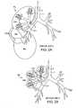
- FIGS. 2A-2Bschematically illustrate example collateral channels CH in the right lung RL.
- FIG. 2Aillustrates a variety of inter-lobar collateral channels CH between the right upper lobe RUL, right middle lobe RML and right lower lobe RLL.
- FIG. 2Billustrates intra-lobar or inter-segmental collateral channels CH which connect individual lung segments (e.g. S, S 1 , S 2 ) within the lung lobes.
- These inter-segmental collateral channelsallow the periphery of each of the lung compartments to communicate with one another and include well-known collateral pathways such as Martin's Channels, pores of Kohn and Lambert's canals.
- the main lobese.g RUL, RML, RLL
- the main lobese.g RUL, RML, RLL
- impermeable fissurescomprised of a double layer of infolded reflections of visceral pleura.
- collateral channels CH between the lungsare considered not present or are minimal.
- interlobar fissuresfrequently do not extend completely to the mediastinum or hilum and are, therefore, incomplete.
- various studieshave described the major fissures to be incomplete in 18% to 73% of cases.
- there are varying degrees of fusion between lobes, and consequently, these areas of parenchymal fusionmay provide a pathway for the spread of disease between lobes and a pathway for collateral air drift or inter-lobar collateral ventilation.
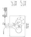
- a method of measuring inter-compartment collateral ventilationhas been to measure resistance to collateral ventilation (R coll ). Assessment of the relationship between steady-state flow through collateral channels (Q coll ) and the pressure drop across them is a direct way for measuring the resistance to collateral ventilation (R coll ). Many investigators have attempted to use this approach in the past but the most simple and versatile way to make this measurement was first described by Hilpert (Hilpert P. Kollaterale Ventilation Habilitationsschirift, aus der Medizinischen. Tubingen, West Germany: Tubingen Universitatsklinik, 1970. Thesis). This method is schematically illustrated in FIG. 3A-3C and includes supplying a constant positive pressure of air (P) to a target area or sealed target compartment C s .
- Pconstant positive pressure of air
- FIG. 3Billustrates a state of steady pressure P.
- the methodalso includes determining the required airflow rate (V coll ) to maintain that pressure P.
- the airflow rateis measured by a flowmeter 8 disposed along the isolation catheter 6 .
- the ratio of P over V collprovides a quantitative measure for the resistance to collateral ventilation.
- a constant airflowmay be injected through one lumen of the isolation catheter 6 while air pressure (P b ) at the site of bronchial obstruction is measured through the other lumen.
- the ratio between P b and Q collequals the resistance through the collateral system, which includes the resistance in the collateral channels R coll and the resistance in the small airways R saw of the isolated compartment C s between the collateral channels CH and the distal end of the catheter 6 .
- this techniquecan be somewhat useful as an experimental tool, however it has significant limitations experimentally and its clinical use poses an additional risk to the patient. Namely, applying positive pressure or constant air flow to a diseased area of the lung can be hazardous if not done correctly. For example in the presence of bullous emphysema, the pressure could enlarge the bullae or create new bulla, or could lead to increased hyperinflation or pneumothorax.
- the presence of inter-compartment collateral ventilationcan be assessed by isolation of the target segment and subsequent introduction of the subject to breath normally with Heliox (21% O 2 /79% He). Detection of tracer gas in the target segment indicates the presence of collateral channels communicating that area with the rest of the lung.
- R collis indirectly measured as the ratio between ⁇ coll and the compliance of the target segment C s .
- Calculations of R coll via this methodare highly dependent on several questionable assumptions, including homogeneity within the obstructed segment and in the surrounding lung.
- Values for R coll reported in the literature using either Hilpert's method or other methodsrange from approximately 10 ⁇ 1 to 10 +2 cmH 2 O/(ml/s) for normal human lungs and from approximately 10 ⁇ 3 to 10 ⁇ 1 cmH 2 O/(ml/s) for emphysematous human lungs.
- a direct, accurate, simple and minimally invasive method of assessing collateral flow in lungsis desired, which also poses minimal risk to the patient.
- methods and devices for quantitatively determining the resistance of these collateral ventilation pathways in the course of diagnosing and treating lung diseaseis also desired. At least some of these objectives will be met by the present invention.
- collateral ventilation of a target compartment within a lung of a patientis assessed by advancement of a catheter through the tracheobronchial tree to a feeding bronchus of the target compartment.
- the feeding bronchusis occluded by the catheter and a variety of measurements are taken with the use of the catheter in a manner which is of low risk to the patient. Examples of such measurements include but are not limited to flow rate and pressure. These measurements are used to determine the presence of collateral ventilation and to quantify such collateral ventilation.
- Collateral ventilationrefers to flow or passage of air from the target lung compartment into one or more adjacent components through passage(s) in or through the natural barriers which form the components.
- the lungs of a patientmay be analyzed for appropriateness of various treatment options prior to treatment.
- levels of collateral ventilationmay be mapped to various target compartments so that the practitioner may determine the overall condition of the patient and the most desired course of treatment.
- EMREndobronchial Volume Reduction
- the lung compartmentmay be analyzed for collateral ventilation prior to treatment to determine the likelihood of success of such treatment.
- undesired levels of collateral ventilationare measured, the collateral ventilation may be reduced to a desired level prior to treatment to ensure success of such treatment.
- the methodcomprises isolating a target lung compartment from at least one adjacent lung compartment(s) usually all adjacent compartments, and allowing the patient to breathe air free from the introduced markers and detecting air flow or accumulation from the isolated lung compartment over time.
- isolatingcomprises introducing a catheter transtracheally to a main bronchus feeding into the target lung compartment and deploying an occlusion member on the catheter to isolate the target lung compartment in the main passageway leading into that compartment.
- detectingmay comprise measuring air flow through a lumen in the catheter while the patient exhales, wherein said air entered the isolated compartment via collateral passages while the patient inhaled. In other instances, detecting comprises accumulating air from the isolated compartment air from the isolated compartment through the catheter over a number of successive breathing cycles, wherein a continuous increase in accumulated air volume indicates collateral flow into the isolated compartment.
- methodsare provided for determining the function or malfunction of an endobronchial prosthesis positioned within a lung passageway of a patient.
- the methodcomprises occluding the lung passageway proximally of the endobronchial prosthesis, allowing the patient to breathe air without any markers, and measuring air flow or accumulation from the lung passageway over time wherein said measurement is correlative to the function or malfunction of the endobronchial prosthesis.
- systemsfor detecting collateral ventilation into a lung compartment in a patient.
- the systemcomprises a catheter adapted to be introduced transtracheally to a bronchus leading to a target lung compartment, an occlusion member on a distal region of the catheter, said occlusion member being adapted to selectively occlude the bronchus, and a flow measurement sensor on the catheter to detect flow of air from the isolated compartment as the patient exhales.
- systemsfor detecting collateral ventilation into a lung compartment in a patient.
- the systemcomprises a catheter adapted to be introduced transtracheally to a bronchus leading to a target lung compartment, an occlusion member or a distal region of the catheter, said occlusion member being adapted to selectively occlude the bronchus and an accumulator connectable to the catheter to accumulate air exhaled from the catheter over time.
- accumulatorsinclude a slack collection bag which has substantially no resistance to filling with air.
- the methodcomprises positioning an instrument within a lung passageway leading to the target lung compartment so that the target lung compartment is isolated, injecting an inert gas into the isolated target lung compartment, generating at least one measurement of pressure within the target lung segment, generating at least one measurement of concentration of inert gas within the target lung segment, and analyzing the at least one target lung compartment with the use of the at least one measurement of pressure and the at least one measurement of concentration of inert gas.
- Analyzingmay comprise determining a degree of hyperinflation.
- the methodmay further comprise determining a treatment plan at least partially based on the determined degree of hyperinflation.
- analyzingmay comprise determining a state of compliance. In such instances, the method may further comprise determining a treatment plan at least partially based on the determined state of compliance. Likewise, analyzing may comprise determining a collateral resistance. In such instances, the method may further comprise determining a treatment plan based on the determined collateral resistance.
- generating the at least one measurement of pressurecomprises generating a plurality of measurements of pressure over a predetermined time period.
- the predetermined time periodmay comprise, for example, approximately one minute.
- generating the at least one measurement of concentration of inert gascomprises generating a plurality of measurements of concentration of inert gas over a predetermined time period.
- the predetermined time periodmay comprise, for example, approximately one minute.
- the inert gasmay comprise helium.
- systemsfor evaluating a target lung compartment comprising an instrument positionable within a lung passageway leading to the target lung compartment so that the target lung compartment is isolated, wherein the instrument includes a mechanism for injecting an inert gas to the target lung segment, at least one sensor which generates measurement data reflecting pressure within the target lung segment, and at least one sensor which generates measurement data reflecting concentration of an inert gas within the target lung segment.
- the systemfurther comprises a processor which performs computations with the use of the measurement data reflecting pressure and the measurement data reflecting concentration of inert gas.
- the computationsmay include calculating a degree of hyperinflation of the target lung compartment, calculating a state of compliance of the target lung compartment, and/or calculating collateral resistance of the target lung compartment.
- the measurement data reflecting pressuremay comprise generating a plurality of measurements of pressure over a predetermined time period. In some instances, the predetermined time period comprises approximately one minute.
- the measurement data reflecting concentration of inert gasmay comprise generating a plurality of measurements of concentration of inert gas over a predetermined time period. In some instances, the predetermined time period comprises approximately one minute.
- the inert gasmay comprise helium.
- treatment guidesare provided to determine a course of treatment for a lung compartment of a patient.
- the guidecomprises a plurality of hyperinflation values, each hyperinflation value representing a degree of hyperinflation of the lung compartment, and/or a plurality of compliance values, each compliance value representing a degree of compliance of the lung compartment, and a plurality of treatment options, wherein each treatment option is correlated to a hyperinflation value and/or a compliance value.
- the guidecomprises a computer program.
- the computer programincludes at least one mathematical computation to generate the plurality of hyperinflation values and/or the plurality of compliance values. The mathematical computation may utilize, for example, pressure and concentration of inert gas values.
- the methodincludes positioning an instrument within a lung passageway leading to the target lung compartment so that the target lung compartment is isolated, allowing the patient to inhale air, generating at least one measurement of at least one characteristic of the inhaled air within or exiting the target lung compartment with the use of the instrument, and determining a level of collateral ventilation into the target lung compartment based on the at least one measurement.
- the at least one characteristicincludes volumetric flow rate and pressure.
- Determining a level of collateral ventilationmay include calculating a value of collateral resistance.
- the methodmay further comprise determining a treatment plan based on the level of collateral ventilation.
- methodsfor evaluating a patient for treatment of a target lung compartment, the method comprising generating at least one measurement associated with the target lung compartment while the patient is breathing air, calculating a level of collateral ventilation into the target lung compartment based on the at least one measurement, and treating the patient based on the calculated level of collateral ventilation.
- Treating the patientmay comprise aspirating the target lung compartment.
- treating the patientmay comprise occluding a lung passageway feeding the target lung compartment.
- occludingcomprises positioning an occlusal stent within the lung passageway.
- Calculatingmay comprise calculating a value of collateral resistance based on the at least one measurement.
- additional treatment guidesare provided to determine a course of treatment for a lung compartment of a patient.
- the guidecomprises a plurality of collateral resistance values, each value representing degree of collateral ventilation of the lung compartment, and a plurality of treatment options, wherein each treatment option is correlated to a collateral resistance value.
- the guidecomprises a computer program.
- the computer programmay include at least one mathematical computation to generate the plurality of collateral resistance values.
- the mathematical computationmay utilize pressure and volumetric flow rate values.
- the guidealso includes a visual display showing a curve representing a relationship between the collateral resistance values and a combination of the pressure and volumetric flow rates.
- FIGS. 1A-1Cillustrate an example of an EVR procedure targeting the right upper lobe of the right lung of a patient.
- FIGS. 2A-2Bschematically illustrate example collateral channels in the right lung.
- FIGS. 3A-3Cschematically illustrates a method of supplying constant positive pressure of air to a target compartment.
- FIGS. 4A-4Dillustrate an embodiment of a minimally invasive method in which a catheter is advanced to the feeding bronchus of a target compartment.
- FIGS. 5A-5D , 6illustrate embodiments of a catheter connected with an accumulator.
- FIGS. 7A-7Bdepict a graphical representation of a simplified collateral system of a target lung compartment.
- FIGS. 8A-8Cillustrate measurements taken from the system of FIGS. 7A-7B .
- FIGS. 9A-9Cillustrate a circuit model representing the system of FIGS. 7A-7B .
- FIGS. 10A-10Billustrate measurements taken from the system of FIGS. 7A-7B .
- FIGS. 11A-11Dillustrate graphical comparisons yielded from the computational model of the collateral system illustrated in FIGS. 7A-7B and FIGS. 9A-9B .
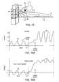
- FIG. 12Aillustrates a two-compartment model which is used to generate a method quantifying the degree of collateral ventilation.
- FIG. 12Billustrates an electrical circuit analog model
- FIGS. 12C-12Eillustrate the resulting time changes in volumes, pressures and gas concentrations in the target compartment and the rest of the lobe.
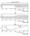
- FIGS. 13A-13Cillustrate changes in measured variables based on degree of effort.
- FIGS. 14A-14Billustrate changes in measured variables based on frequency of effort.
- FIGS. 15 , 16 A- 16 Billustrate the use of continuous positive airway pressure to assist in the detection of collateral ventilation.
- FIG. 17illustrates a single breath technique
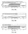
- FIGS. 18A-18Cillustrate example flow, volume and pressure measurement curves respectively.
- FIG. 19illustrates flow measured via a catheter wherein differences in the waveform characteristic of inspiration versus exhalation facilitate determining whether collateral ventilation exists.
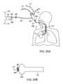
- FIGS. 20A-20Billustrate an embodiment of an isolation catheter including a bronchoscope.
- FIGS. 21A-21Cillustrate the performance of a collateral ventilation test through an occlusal stent.
- FIGS. 22A-22Cillustrate the use of carbon dioxide to indicate collateral flow.
- FIGS. 23A-23Cillustrate the use of tracer gas to indicate collateral flow.
- FIGS. 24A-24Cillustrate the use of oxygen to indicate collateral flow.
- FIGS. 25A-25Cillustrate methods and devices for seal testing of an isolation catheter.
- FIG. 26illustrates an embodiment of a system of the present invention for measuring collateral ventilation in one or more lung passageways.
- FIG. 27illustrates an embodiment of a screen indicating collateral ventilation measurements and mapping.
- FIG. 28illustrates an embodiment of a method of treating a patient.
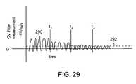
- FIG. 29illustrates an example iterative process of reducing collateral ventilation prior to EVR.
- FIGS. 4A-4Dillustrate an embodiment of a minimally invasive method in which a catheter 10 is advanced through a tracheobronchial tree to the feeding bronchus B of the target area C s , the compartment targeted for treatment or isolation.
- the catheter 10comprises a shaft 12 having at least one lumen therethrough and an occlusion member 14 mounted near its distal end.
- the catheter 10is equipped to seal the area between the catheter shaft 12 and the bronchial wall such that only a lumen inside the catheter which extends the entire length of the catheter is communicating with the airways distal to the seal.
- the seal, or isolationis accomplished by the use of the occlusion member 14 , such as an inflatable member, attached to the distal tip of the catheter 10 .
- a one-way valve 16On the opposite end of the catheter 10 , external to the body of the patient, a one-way valve 16 , a flow-measuring device 18 or/and a pressure sensor 20 are placed in series so as to communicate with the catheter's inside lumen.
- the one-way valve 16prevents air from entering the target compartment C s from atmosphere but allows free air movement from the target compartment C s to atmosphere.
- the isolated compartment C swill unsuccessfully attempt to draw air from the catheter lumen during inspiration of normal respiration of the patient. Hence, during exhalation no air is returned to the catheter lumen. In the presence of collateral channels, as illustrated in FIGS.
- an additional amount of airis available to the isolated compartment C s during the inspiratory phase of each breath, namely the air traveling from the neighboring compartment(s) C through the collateral channels CH, which enables volumetric expansion of the isolated compartment C s during inspiration, resulting during expiration in air movement away from the isolated compartment C s to atmosphere through the catheter lumen and the collateral channels CH.
- airis expelled through the catheter lumen during each exhalation and will register as positive airflow on the flow-measuring device 18 .
- This positive airflow through the catheter lumenprovides an indication of whether or not there is collateral ventilation occurring in the targeted compartment C s .
- This technique of measuring collateral flow in a lung compartmentis analogous to adding another lung compartment, or lobe with infinitely large compliance, to the person's lungs, the added compartment being added externally.
- some airmay be expelled through the catheter lumen during exhalation in the absence of collateral channels, however at a different rate, volume and trend than that in the presence of collateral channels.
- the catheter 10is connected with an accumulator or special container 22 as illustrated in FIGS. 5A-5D , 6 .
- the container 22has a very low resistance to airflow, such as but not limited to e.g. a very compliant bag or slack collection bag.
- the container 22is connected to the external end or distal end 24 of the catheter 10 and its internal lumen extending therethrough in a manner in which the inside of the special container 22 is communicating only with the internal lumen.
- the special container 22does not expand.
- the target compartment Csis sealed by the isolation balloon 14 so that air enters and exits the non-target compartment C.
- the special container 22will initially increase in volume because during the first exhalation some portion of the airflow received by the sealed compartment C s via the collateral channels CH will be exhaled through the catheter lumen into the external special container 22 .
- the properties of the special container 22are selected in order for the special container 22 to minimally influence the dynamics of the collateral channels CH, in particular a highly inelastic special container 22 so that it does not resist inflation.
- the volume in the special container 22will continue to increase during each subsequent respiratory cycle because the volume of air traveling via collateral channels CH to the sealed compartment C s will be greater during inspiration than during expiration, resulting in an additional volume of air being forced through the catheter lumen into the special container 22 during exhalation.
- a flow-measuring device 18 or/and a pressure sensor 20may be included, as illustrated in FIG. 6 .
- the flow-measuring device 18 and/or the pressure sensor 20may be disposed at any location along the catheter shaft 12 (as indicated by arrows) so as to communicate with the catheter's internal lumen.
- the flow-measuring device 18 and the pressure sensor 20may be placed in series.
- a one-way valve 16may also be placed in series with the flow-measuring device 18 or/and pressure sensor 20 .
- the flow-measuring device 18can be placed instead of the special container 22 or between the special container 22 and the isolated lung compartment, typically at but not limited to the catheter-special container junction, to measure the air flow rate in and out of the special container and hence by integration of the flow rate provide a measure of the volume of air flowing through the catheter lumen from/to the sealed compartment C s .
- measuring flowcan take a variety of forms, such as but not limited to measuring flow directly with the flow-measuring device 18 , and/or indirectly by measuring pressure with the pressure sensor 20 , and can be measured anywhere along the catheter shaft 12 with or without a one-way valve 16 in conjunction with the flow sensor 18 and with or without an external special container 22 .
- a constant bias flow ratecan be introduced into the sealed compartment C s with amplitude significantly lower than the flow rate expected to be measured due to collateral flow via the separate lumen in the catheter 10 .
- the bias flow ratecan be, but not limited to one tenth (0.1) or one one-hundredth (0.01) of that amount of equal or opposite amplitude.
- the purpose of the bias flowis to continuously detect for interruptions in the detection circuit (i.e., the working channel of the bronchoscope and any other tubing between the flow meter and catheter) such as kinks or clogs, and also to increase response time in the circuit (due to e.g. inertia).
- a quick flush of gas at a high flow rate(which is distinguished from the collateral ventilation measurement flow rate) can periodically be introduced to assure an unclogged line.
- the degree of collateral ventilationmay be quantified by methods of the present invention.
- the degree of collateral ventilationis quantified based on the resistance through the collateral system R coll .
- R collcan be determined based on the following equation:
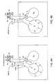
- FIGS. 7A-7Bdepict a graphical representation of a simplified collateral system of a target lung compartment C s .
- a single elastic compartment 30represents the target lung compartment C s and is securely positioned inside a chamber 32 to prevent any passage of air between the compartment 30 and the chamber 32 .
- the chamber 32can be pressurized to a varying negative pressure relative to atmosphere, representing the intrathoracic pressure P pl .
- the elastic compartment 30which represents the target compartment in the lung C s , communicates with the atmospheric environment through passageway 40 .
- the elastic compartment 30also communicates with the atmospheric environment through collateral pathway 41 , representing collateral channels CH of the target compartment of the lung C s .
- a catheter 34is advanceable through the passageway 40 , as illustrated in FIGS. 7A-7B .
- the catheter 34comprises a shaft 36 , an inner lumen 37 therethrough and an occlusion member 38 mounted near it's distal end.
- the catheter 34is specially equipped to seal the area between the catheter shaft 36 and the passageway 40 such that only the lumen 37 inside the catheter 34 , which extends the length of the catheter 34 , allows for direct communication between the compartment 30 and atmosphere.
- a flow-measuring device 42 and a pressure sensor 44are placed in series to detect pressure and flow in the catheter's inside lumen 37 .
- a one-way valve 48 positioned next to the flow measuring device 42allows for the passage of air in only one direction, namely from the compartment 30 to atmosphere.
- the flow measuring device 42 , the pressure sensor device 44 and the one-way valve 48can be placed anywhere along the length of the catheter lumen, typically at but not limited to the proximal end of the catheter shaft 36 .
- measuring pressure inside the compartment 30can be accomplished in a variety of forms, such as but not limited to connecting the pressure sensor 44 to the catheter's inside lumen 37 .
- itcan also be accomplished by connecting the pressure sensor 44 to a separate lumen inside the catheter 34 , which extends the entire length of the catheter 34 communication with the airways distal to the seal.
- the compartment 30may only communicate to atmosphere either via the catheter's inside lumen 37 representing R saw and/or the collateral pathway 41 representing R coll . Accordingly, during inspiration, as illustrated in FIG. 7A , P p1 becomes increasingly negative and air must enter the compartment 30 solely via collateral channels 41 . Whereas during expiration, illustrated in FIG. 7B , air may leave via collateral channels 41 and via the catheter's inside lumen 37 .
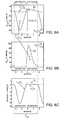
- FIGS. 8A-8Cillustrate measurements taken from the system of FIGS. 7A-7B during inspiration and expiration phases.
- FIG. 8Aillustrates a collateral flow curve 50 reflecting the flow Q coll through the collateral pathway 41 .
- FIG. 8Billustrates a catheter flow curve 52 reflecting the flow Q fm through the flow-measuring device 42 .
- FIG. 8Aillustrates a negative collateral flow curve 50 and
- FIG. 8Billustrates a flat, zero-valued catheter flow curve 52 .
- a smaller amount of airflows back to atmosphere through the collateral pathway 41 , as illustrated by the positive collateral flow curve 50 of FIG. 8A , while the remaining amount of air flows through the catheter lumen 37 back to atmosphere, as illustrated by the positive catheter flow curve 52 of FIG. 8B .
- the volume of air flowing during inspiration and expirationcan be quantified by the areas under the flow curves 50 , 52 .
- the total volume of air V 0 entering the target compartment 30 via collateral channels 41 during inspirationcan be represented by the colored area under the collateral flow curve 50 of FIG. 8A .
- V 2 over T resprepresents the net flow rate of air entering the target compartment 30 via the collateral channels 41 and returning to atmosphere through a different pathway during T resp .
- the system illustrated in FIGS. 7A-7Bcan be represented by a simple circuit model as illustrated in FIGS. 9A-9C .
- the air storage capacity of the alveoli confined to the isolated compartment 30 representing C sis designated as a capacitance element 60 .
- the pressure gradient (P s -P b ) from the alveoli to atmosphere via the catheter's inside lumen 37is caused by the small airways resistance, R saw , and is represented by resistor 64 .
- the pressure gradient from the alveoli to atmosphere through the collateral channelsis generated by the resistance to collateral flow, R coll , and is represented by resistor 62 .
- the elasticity of the isolated compartment 30is responsible for the volume of air obtainable solely across R coll during the inspiratory effort and subsequently delivered back to atmosphere through R saw and R coll during expiration.
- Pressure changes during respirationare induced by the variable pressure source, P pl representing the varying negative pleural pressure within the thoracic cavity during the respiratory cycle.
- An ideal diode 66represents the one-way valve 48 , which closes during inspiration and opens during expiration. Consequently, as shown in FIGS. 10A-10B , the flow measured by the flow meter (Q fm ) is positive during expiration and zero during inspiration, whereas the pressure recorded on the pressure sensor (P b ) is negative during inspiration and zero during expiration.
- FIG. 11Adisplays the absolute values of mean Q fm (
- the valuesdenote independent realizations of computer-generated data produced with different values of R coll while R saw is kept constant at 1 cmH 2 O/(ml/s).
- FIG. 11Adisplays the absolute values of
- FIGS. 11A-11Bshows the model parameters R coll +R saw plotted together with
- the valuesdenote independent realizations of computer-generated data produced with different values of R saw while R coll is kept constant at 1 cmH 2 O/(ml/s). It becomes quite apparent from FIGS. 11A-11B that the flow is maximal when R coll ⁇ R saw and diminishes to zero as R coll approaches the limits of either “overt collaterals” or “no collaterals”. Accordingly, small measured flow Q fm can mean both, very small and very large collateral channels and hence no clear-cut decision can be made regarding the existence of collateral ventilation unless R coll +R saw is determined as
- FIGS. 11C-11Dsupplement FIGS. 11A-11B as it shows how the measured flow Q fm continuously diminishes to zero as R saw becomes increasingly greater than R coll and furthermore increases to a maximum, as R saw turns negligible when compared to R coll .
- R sawis very small compared to R coll , practically all gas volume entering the target compartment via the collateral channels travels back to atmosphere through the small airways and very little gas volume is left to return to atmosphere via the collateral channels as the isolated compartment empties.
- results in an accurate representation of R coll +R saw regardless of the underlying relation amongst R coll and R saw .
- R collIn a healthy human, resistance through collateral communications, hence R coll , supplying a sublobar portion of the lung is many times (10-100 times) as great as the resistance through the airways supplying that portion, R saw (Inners 1979, Smith 1979, Hantos 1997, Suki 2000). Thus in the normal individual, R coll far exceeds R saw and little tendency for collateral flow is expected. In disease, however, this may not be the case (Hogg 1969, Terry 1978). In emphysema, R saw could exceed R coll causing air to flow preferentially through collateral pathways.
- the above described models and mathematical relationshipscan be used to provide a method which indicates the degree of collateral ventilation of the target lung compartment of a patient, such as generating an assessment of low, medium or high degree of collateral ventilation or a determination of collateral ventilation above or below a clinical threshold.
- the methodalso quantifies the degree of collateral ventilation, such generating a value which represents R coll .
- a resistance valueindicates the geometric size of the collateral channels in total for the lung compartment.
- FIG. 12Aillustrates a two-compartment model which is used to generate a method quantifying the degree of collateral ventilation, including a) determining the resistance to segmental collateral flow R coll , b) determining the state of segmental compliance C s , and c) determining the degree of segmental hyperinflation q s .
- C scharacterizes the compliance of the target compartment or segment.
- C Lrepresents the compliance of the rest of the lobe.
- R colldescribes the resistance to the collateral airflow.
- ⁇ collR coll ⁇ C S ⁇ C L C S + C L ⁇ C eff ( 15 )
- FIGS. 12C-12Eillustrate the resulting time changes in volumes, pressures and gas concentrations in the target compartment C s and the rest of the lobe C L .
- Eqs. 16-21state the mathematical representation of the lung volumes, pressures and gas concentrations at two discrete points in time, t 1 and t 2 .
- the following methodsmay be performed for each compartment or segment independently: 1) Assess the degree of segmental hyperinflation, 2) Determine the state of segmental compliance, 3) Evaluate the extent of segmental collateral communications.
- the degree of hyperinflation in the target segment, qs(0)can be determined by solving Eq. 16 for qs(0) and subsequently substituting qs(t 1 ) from Eq. 20 into Eq. 16 after appropriate solution of Eq. 20 for qs(t 1 ) as
- the state of compliance in the target segment, C Scan be determined simply by solving Eq. 18 for C S as
- the compliance of the rest of the lobe, C Lcan be determined by solving Eq. 19 for C L and subsequently substituting C S with Eq. 23. Accordingly,
- the degree of hyperinflation in the rest of the lobecan be determined by solving Eq. 17 for q L (0) and subsequently substituting qs(t 2 )+q L (t 2 ) from Eq. 21 into Eq. 17 after appropriate solution of Eq. 21 for qs(t 2 )+q L (t 2 ).
- Equation 26provides an additional measurement for check and balances of all volumes at the end of the clinical procedure.
- collateral ventilationis dependent on the patient's respiratory mechanics. For instance, a patient that is breathing very shallow at ⁇ 2 cmH 2 O of pleural pressure creates a minimal amount of lung compartment expansion and hence the collateral channels remain somewhat resistive. The measured collateral ventilation will therefore be correspondingly low.
- an aspect of the present inventionincludes measuring the patient breathing effort so that the collateral ventilation measurement can be calculated as a function of the degree and/or frequency of that effort, in effect normalizing the measurement to any situation.
- the breathing effortcan be measured in terms of tidal volume inspired by the patient, or by inspiratory flow rate, peak inspiratory flow rate, pleural pressure created (for example as measured by an esophageal pressure transducer), upper airway pressure, work-of-breathing in joules of energy exerted per liter of air inspired, thoracic cavity expansion (such as measured by chest wall expansion) or other means.
- FIGS. 13A-13Cillustrate changes in measured variables based on degree of effort, i.e. during shallow and deep breathing. For example, FIG.
- FIG. 13Aillustrates pressure measurements in a target lung compartment.
- the volume leaving the target lung compartment and accumulated over timemay be calculated by integration of the volumetric flow rate data from FIG. 13B .
- the slope denoting the change in volume over timecorresponds to the mean flow rate.
- a specially configured breathing effort sensoris provided.
- Such sensorsinclude but are not limited to a mouthpiece that allows for simultaneous passage through the mouth of the isolation catheter 10 and measurement of airflow through the mouthpiece (around the outside of the catheter shaft).
- FIGS. 14A-14Billustrate changes in measured variables based on frequency of effort, i.e. during fast and slow breathing.
- FIG. 14Aillustrates volumetric flow rate measurements in a target lung compartment.
- the volume accumulated over timesuch as within a specialized container, may be calculated by integration of the volumetric flow rate data from FIG. 14A .
- the slope denoting the change in volume over timecorresponds to the mean flow rate.
- the units of measure of the collateral ventilation variablewhich takes into account the degree and/or frequency of the involved respiratory effort, are therefore reported in units of A/B where A is the measurement of collateral ventilation and B is the measurement of respiratory drive.
- the result of the normalized collateral ventilation variablecan be reported, for example, as but not limited to an average, a peak value or a range.
- the desired measurement and reporting of the collateral ventilation normalized resultincludes a mathematical relation and in its most convenient form, a system and the necessary devices to acquire all the needed measured parameters in a single instrument to apply the said mathematical relation to perform the calculation.
- the normalization technique subject to this inventionis independent of the exact collateral ventilation measurement method; any collateral ventilation measurement method can be used with this novel normalization technique.
- CPAPcontinuous positive airway pressure
- FIG. 15the targeted lung compartment is isolated as previously described with the placement of an isolation catheter into the targeted lung compartment of the patient P.
- the isolation catheteris placed with the use of a bronchoscope 60 providing an endoscopic view with the use of a monitor 62 .
- CPAPis administered via a nasal or oral-nasal non-invasive mask 64 , positionable over the patient's face, which is connected to a CPAP ventilator 66 .
- This specially configured mask 64simultaneously allows for the administration of CPAP, the passage of the isolation catheter, and optionally breath sensors to measure breathing effort.
- the isolated target lung compartmentis not subjected directly to CPAP, however if collateral channels are present, the detection of these channels is facilitated because the CPAP amplifies the degree of airflow across the channels due to simple pressure gradient laws. Further hyperinflation due to air trapping is prevented using safe pressure levels and I:E ratios. Therefore, CPAP increases the measurement sensitivity of the collateral ventilation measurement technique of using an externally placed but communicating flow meter or special container.
- FIG. 16Aillustrates example collateral flow measurements recorded by a flow meter.
- the CPAP maskis positioned on the patient and shortly thereafter CPAP is started resulting in an amplified signal.
- the flow signal 70is relatively weak showing spontaneous breathing without CPAP.
- the flow signal 70 ′is stronger showing an amplification of the flow rate signal due to CPAP.
- FIG. 16Billustrates example pressure measurements taken in lung compartments that are not isolated by the isolation catheter (the pressure in the isolated lung compartment is less, closer to normal).
- the CPAP maskis positioned on the patient and shortly thereafter CPAP is started resulting in an amplified signal.
- the pressure signal 72is relatively weak showing spontaneous breathing without CPAP.
- the pressure signal 72 ′is stronger showing an amplification of the pressure signal due to CPAP.
- a single breath techniqueis used wherein the collateral ventilation and, if so measured, the patient's breathing effort, are measured for a single breath.
- the targeted lung compartment C sis cannulated and isolated with an externally communicating catheter 10 as previously described.
- the patient Pis shown having the catheter 10 advanced into the targeted lung compartment C s and the flowmeter 18 and/or pressure sensor 20 and one-way valve 16 residing outside of his mouth.
- the flowmeter 18 and/or pressure sensor 20is linked to a computer 80 which acquires the appropriate data.
- Example flow rate 82 and pressure curves 84are shown.
- the cooperative patient Pis instructed to breath out as much air as possible with a forced and extended exhalation effort (t 1 ), and at the end of exhalation (which is detectable with the breath sensing devices) the target lung compartment C s is isolated (t 2 ).
- the patientthen initiates a maximal inspiratory effort (t 3 ) and starts a deep exhalation (t 4 ) which then ends at (t 5 ). It is presumed that any air exiting the isolation catheter 10 during the deep exhalation (t 4 -t 5 ) would be from collateral ventilation. If collaterals were present, a flow peak 86 and a pressure peak 88 .
- the collateral ventilation(and breathing effort if so measured) can be measured and reported as a function of a single breath peak inspiratory effort. Results can be reported normalized or unnormalized for the complete breath, a peak value during the breath, an average value during the breath, the value during a portion of the breath, for example but not limited to the first one second of the breath, an average value of a number of separate single breath measurements or maneuvers.
- the processing unitin the case of this embodiment includes the requisite algorithms and control systems to obtain and process the measurement as needed.
- airflow measurementsare made both before, during and after isolation of the targeted lung compartment C s , wherein such measurements are analyzed to evaluate collateral ventilation.
- an external flow measuring deviceis configured to measure flow into and out of a targeted lung compartment C s via an externally communicating catheter 10 placed into the compartment C s , as previously described.
- the compartment C sis cannulated with the catheter 10 , but without isolating the bronchus.
- the flow measurement through the catheter lumenis made, resulting in a flowrate curve 90 at baseline.
- the bronchusis isolated by inflating the occluder balloon and the amplitude of the flowrate curve 90 increases if there is collateral flow.
- FIG. 18B and FIG. 18CCorresponding volume and pressure measurement curves are shown in FIG. 18B and FIG. 18C respectively.
- Comparison of the airflow magnitude and direction as measured at the external flow-sensing deviceprovides additional information about the collateral channels in the target compartment and/or verification of the system's integrity. For example, comparison of the amplitudes before and after isolation can also be used to quantify/or normalize the degree of flow via collateral channels and/or check for adequate isolation of the target compartment.
- This aspect of the inventionincludes the requisite systems and devices for processing the pre and post airflow measurements and may include an automatic isolation system controlled by instrumentation embedded in the processing unit.
- flowis measured via a catheter 10 as previously described.
- the occlusion member 14is positioned and inflated to isolate the target lung compartment C s .
- the ratio VI/VE in the presence of collateral ventilationdiffers from the ratio VI/VE in the absence of collateral ventilation.
- the isolation catheter 10includes a fiberoptic endoscope, or bronchoscope 100 , with optional built-in imaging, illumination and/or steering.
- FIG. 20Aillustrates the bronchoscope 100 inserted into an external sheath 102 having an occlusion member 104 and joined at a sheath proximal connector 106 .
- Exemplary embodiments of suitable external sheaths having inflation cuffs for use with bronchoscopes or other endoscopic instrumentsare described in U.S. Pat. No. 6,585,639, incorporated herein by reference for all purposes.
- FIG. 20Bprovides a more detailed illustration of the distal end of the bronchoscope 100 and sheath 102 of FIG. 20A .
- a working channel 103 of the bronchoscope 100is shown along with imaging features 105 .
- the bronchoscope 100 and sheath 102are advanced down the trachea T of the patient P to the target lung compartment C s so that the inflation cuff 104 is positioned to isolate the target lung compartment C s .
- the sheath 102also includes a cuff inflation line/valve 108 which can be used to measure cuff pressure.
- the bronchoscope 100includes an imaging cable 110 and light cable 112 , as shown.
- a suction line 114may also be connected with the bronchoscope 100 .
- the shaft of the bronchoscopeincludes a lumen extending most of its length to which a flow-measuring device 116 is connected external to the patient P. As shown, the flow-measuring device 116 has a power cord 118 and a signal to main processor 120 .
- Tubing 122connects the bronchoscope 100 to an inlet 124 of the flow-measuring device 110 , wherein a check valve 126 is present along the tubing 122 . Air, gasses or other measured entities are released from the flow-measuring device 116 via an outlet 128 .
- the sheath 102 or an outer sleevemay be equipped with additional lumens that extend across the occlusion member 104 for the purpose of measuring flow or other respiratory or physiological parameters, or for delivering agents or tracer gases.
- FIGS. 21A-21Cillustrate the performance of a collateral ventilation test through an occlusal stent 130 .
- an occlusal stent 130is shown sealing a bronchial lumen leading to a target lumen compartment C s .
- a bronchoscope 100is shown advanced to a position near the occlusal stent 130 .
- a catheter 132is advanced through the bronchoscope 100 and through the occlusal stent 130 , accessing the target lung compartment C s .
- the occlusal stent 130includes a valve which allows the catheter 132 to advance therethrough while maintaining isolation of the target lung compartment C s .
- Measurements of pressure, flow or other respiratory or physiological parametersare then taken, with or without a one-way valve and/or external special container, either at the tip of the catheter 132 in the targeted lung compartment C s or at the proximal end of the catheter 132 , external to the patient, through a lumen in the catheter 132 that extends the catheter's length.
- volume reduction therapymay then be performed by aspirating through the catheter 132 and stent 132 , as illustrated in FIG. 21C . The catheter 132 is then removed and the volume reduction maintained.
- gas temperatureis measured at some point along the catheter lumen either instead of the flow rate measurement or to complement the flow rate measurement, in order to further interpret the data being collected and/or to further distinguish between expiratory flow and inspiratory flow through the catheter lumen.
- respiratory gas composition of the target lung compartment C sis measured to facilitate further interpretation of the airflow data gathered by a flow measuring device.
- a flow measuring devicemay be taken separately or simultaneously with the flow rate measurements.
- a certain decay rate of O 2 composition in the gas at the external end of the cathetermay be indicative of no or little collateral flow
- a slower or no decay rate of O 2may be indicative of collateral flow since fresh oxygen inspired by the patient can enter the target compartment C s via the collateral channels.
- Other gases, for example CO 2can also be measured, as illustrated in FIGS. 22A-22C .
- FIG. 22A-22Ccan also be measured, as illustrated in FIGS. 22A-22C .
- 22Aillustrates a catheter 140 advanced through a bronchoscope 100 having an occlusion member 142 which seals a bronchial lumen leading to a target lumen compartment C s .
- the catheter 140is connected with a flow sensing device 144 , as described above.
- the catheter 140is connected with a gas sensing device 146 , such as a capnographer, having a gas sensor 148 . Measurements of flow or other respiratory or physiological parameters are then taken, with or without a one-way valve 149 and/or external special container, either at the tip of the catheter 140 in the targeted lung compartment C s or at the proximal end of the catheter 140 , external to the patient, through a lumen in the catheter 140 that extends the catheter's length.
- FIG. 22B-22Cillustrate example flow measurements 150 recorded by the flow sensing device 144 , along with corresponding CO 2 concentration measurements 152 .
- FIG. 22Billustrates a situation wherein there is no collateral flow between the target compartment C s and a neighboring compartment C.
- FIG. 22Cillustrates a situation wherein there is collateral flow between the target compartment C s and the neighboring compartment C.
- differencescan be seen in both the flow measurements 150 and CO 2 concentration measurements 152 . Therefore, measurement of various gases can be used to complement flow measurements for data interpretation.
- the gas composition together with the flow datacan also be used to normalize the collateral flow measurement as previously described.
- tracer gas infusion and measurementmay be used to facilitate further interpretation of the airflow data gathered by a flow measuring device. Measurement of the composition of tracer gas, simultaneous with the measurement of airflow as previously described, will facilitate distinguishing between air from a neighboring lung compartment C entering through collateral channels and air that was native to the targeted isolated lung compartment C s .
- the tracer gasis inert and is not absorbed by the tissue or blood stream in order to eliminate that variable in the collateral flow measurement, however optionally the gas can be a diffusible or absorbable gas for purposes described later.
- 23Aillustrates a catheter 154 advanced through a bronchoscope 100 having an occlusion member 156 which seals a bronchial lumen leading to a target lumen compartment C s .
- the catheter 154is connected with a flow sensing device 158 , as described above.
- the catheter 154is connected with a tracer gas sensing device 160 and a tracer gas injection device 162 , such as a syringe.
- FIG. 23B-23Cillustrate example flow measurements 164 recorded by the flow sensing device 166 , along with corresponding tracer gas concentration measurements 168 .
- FIG. 23Billustrates a situation wherein there is no collateral flow between the target compartment C s and a neighboring compartment C. As shown, tracer gas concentration remains steady.
- FIG. 22Cillustrates a situation wherein there is collateral flow between the target compartment C s and the neighboring compartment C.
- the tracer gas concentrationdecays due to leakage through collateral channels.
- the tracer gas decay rate and flow measurementsmay be compared arithmetically to determine if collateral channels are present and/or the magnitude or size of the channels.
- absorbable gas infusion and measurementmay be used to facilitate further interpretation of the airflow data gathered by a flow measuring device.
- Measurement of the composition of absorbable gassuch as oxygen
- FIG. 24Aillustrates a catheter 170 advanced through a bronchoscope 100 having an occlusion member 172 which seals a bronchial lumen leading to a target lumen compartment C s .
- the catheter 170is connected with a flow sensing device 174 , as described above.
- the catheter 170is connected with a gas delivery system 176 and gas source 178 .
- the gas delivery system 176 and flow sensing device 174are connected with the catheter 170 via a switching valve 180 which allows the flow sensing device 174 to monitor collateral flow after the absorbable gas is delivered. Measurements of flow or other respiratory or physiological parameters are then taken, with or without a one-way valve and/or external special container, either at the tip of the catheter 170 in the targeted lung compartment C s or at the proximal end of the catheter 170 , external to the patient, through a lumen in the catheter 170 that extends the catheter's length.
- FIG. 23B-23Cillustrate example flow measurements 182 recorded by the flow sensing device 174 , along with corresponding absorbable concentration measurements 184 .
- FIG. 23Billustrates a situation wherein there is no collateral flow between the target compartment C s and a neighboring compartment C. As shown, absorbable gas concentration decays via blood diffusion.
- FIG. 22Cillustrates a situation wherein there is collateral flow between the target compartment C s and the neighboring compartment C. As illustrated, the absorbable gas concentration decays at a faster rate due to diffusion and leakage through collateral channels. The absorbable gas decay rate and flow measurements may be compared arithmetically to determine if collateral channels are present.
- FIG. 25Aillustrates a distal end of an isolation catheter 10 having an occlusion member 14 mounted thereon.
- the occlusion member 14is shown inflated within a lung passageway LP. It is desired that the occlusion member 14 seals effectively to occlude the passageway LP, otherwise leakage by the occlusion member 14 may, for example, be mistaken for collateral flow thereby introducing error to the collateral flow measurements. Therefore, leak-testing may be performed to ensure appropriate seal.
- the isolation catheter 10includes a gas delivery lumen 200 and a gas sampling lumen 202 .
- the gas delivery lumen 200exits the catheter 10 distally of the occlusion member 14 , such as through a delivery port 204 , as illustrated.
- the gas sampling lumen 202exits the catheter 10 proximally of the occlusion member 14 , such as through sampling port 206 .
- FIG. 25Billustrates a cross-sectional view of FIG. 25A and shows the gas delivery lumen 200 and gas sampling lumen 202 extending through the wall of the catheter 10 while a main lumen 208 extends throughout the length of the catheter 10 .
- An inert gasis introduced through the isolation catheter 10 and is delivered through the delivery port 204 . As illustrated in FIG.
- concentration of the inert gas within the lung passageway LPremains steady immediately after introduction of the gas, as indicated by curve 210 .
- a vacuumis applied to the sampling lumen 202 , as indicated by curve 212 .
- gas leakage between the occlusion member 14 and the wall of the lung passageway LPwill be suctioned into the sampling lumen 202 and measured, as indicated by curve 214 .
- Such a leak testmay be manual, automatic, or sem-automatic. Any processing/control unit external to the body for collateral ventilation testing may include the requisite controls and measuring devices for such leakage measurements.
- seal testingmay alternatively or in addition be achieved by monitoring pressure within the occlusion member 14 .
- an inflation lumen 216is shown extending through the wall of the isolation catheter 10 .
- the inflation lumen 216extends to the occlusion member 14 to pass fluid to the occlusion member 14 for inflation.
- the inflation lumen 216is attached at its proximal end to a pressure gauge to measure pressure within the occlusion member 14 . If the measured pressure falls below a desired level for adequate sealing, the pressure may be increased automatically or manually. Such pressure measurements may be taken continuously or semi-continuously.
- FIG. 26illustrates an embodiment of a system of the present invention for measuring collateral ventilation in one or more lung passageways of a patient.
- the systemincludes a bronchoscope 100 inserted into an external sheath 102 having an occlusion member 104 and joined at a sheath proximal connector 106 .
- a working channel 103extends within the bronchoscope 100 to a side port 231 (for introduction of a catheter or other instrument to the working lumen 103 ) and a connector 230 .
- a suction line 232connects the working channel 103 with wall suction via the connector 230 .
- the connector 230is used to connect the working channel 103 with a control valve 236 .
- the control valve 236is in turn connected with an electronic unit 238 which includes an electronic control module, a signal acquisition unit and a signal processing unit.
- the electronic unit 238also houses an oxygen delivery compartment 240 containing oxygen for delivery through an oxygen line 242 to the control valve 236 and to the working lumen 103 of the bronchoscope 100 .
- a carbon dioxide sensor 246is provided which is connected to a carbon dioxide line 248 which also connects with the control valve 236 and the working lumen 103 .
- a flow meter 250is connected to a collateral ventilation line 252 which also connects with the control valve 236 and the working lumen 103 .
- the control valve 236is manipulated by control signals 254 sent from the electronic unit 238 .
- a display 256is also connected with the electronic unit 238 for visual display of measurement data.
- the systemalso includes a pressure transducer 258 which is connected with the occlusion member 104 via an inflation line 260 .
- the inflation line 250also includes an inflation port 262 for introducing an inflation fluid to the occlusion member 104 .
- the system of FIG. 26may be used to perform a variety of the methods, measurements and treatments described herein.
- an external special container filled with O 2 connected to a targeted compartment via an isolation catheteris included at least by means of using the constituent parts of separate embodiments.
- two of the above embodimentscan be combined such that two external special containers are filled with different tracer gases and the special containers connected each to separate isolation catheters that are each isolating neighboring lung areas; analysis of the flow and gas composition in the special containers after a number of breaths may be correlative to collateral ventilation between the areas.
- Systems, methods and devices of the present inventionmay be used to evaluate any number of target compartments C s within the lungs of a patient.
- levels of collateral ventilationmay be mapped to the target compartments so that the practitioner may determine the overall condition of the patient and the most desired course of treatment.
- the right upper lung lobe (RUL)may be isolated and tested for collateral ventilation between it and the neighboring right middle lobe (RML).
- the isolation cathetermay be advanced deeper into the tracheobronchial tree to, for example, the apical segment of the right upper lobe and that segment can be tested for collateral ventilation between it and the neighboring anterior segment and posterior segments.
- FIG. 27illustrates an embodiment of a screen 280 indicating such measurements and mapping, wherein such a screen 280 may be seen on the display 256 of FIG. 26 .
- the screen 280shows bar graphs 282 indicating a numerical value of collateral ventilation (or collateral ventilation resistance) between specific lung areas.
- a bar graph 282is shown between the RUL and RML indicating the numerical value of collateral ventilation between these two lobes.
- bar graphs 282are shown between individual segments within each lobe.
- the RULhas target compartments denoted B 1 , B 2 , B 3
- the RMLhas target compartments denoted B 4 , B 5 , B 6 , and B 7
- the right lower lobe (RLL)has target compartments denoted B 8 , B 9 , and B 10
- the left upper lobe (LUL)has target compartments denoted B 1 , B 2 , B 3 , B 4 , B 5 , and B 6
- the left lower lung (LLL)has target compartments denoted B 8 , B 9 , B 10 .
- a bar graph 282 extending between B 1 and B 2 within the RULindicates a numerical value of collateral ventilation (or collateral ventilation resistance) between the specific B 1 and B 2 target compartments.
- the screen 280includes a visual depiction 284 of at least a portion of the lungs mapping the collateral ventilation data to the appropriate areas of the lungs.
- the visual depiction 284may include fissures between the lobes or target compartments wherein the shading of the fissure indicates the completeness of the fissure. In some embodiments, a darker fissure indicates a complete fissure and a lighter fissure indicates an incomplete fissure.
- a usermay select an area of interest to display a cut-away view of the fissures in the selected area of interest.
- the screen 280may include a link button 286 which changes the screen 280 to another screen 280 ′ depicting measurement data of other variables, such as gas exchange data or other diagnostic measurement data.
- the practitionermay use some or all of the visual information provided to assess the condition of the patient and determine the treatment plan.
- FIG. 28illustrates an embodiment of a method 300 of treating a patient.
- the patientis referred by a non-specialist to a specialist in lung disease and treatment 302 .
- the patientthen undergoes computed tomography (CT) 304 to produce detailed images of structures inside the body, particularly the lungs.
- CTcomputed tomography
- a CT scannerdirects a series of X-ray pulses through the body. Each X-ray pulse lasts only a fraction of a second and represents a “slice” of the organ or area being studied.
- the slices or picturesare recorded on a computer and can be saved for further study or printed out as photographs.
- the patientalso undergoes pulmonary function testing (PFT) 304 .
- PFTpulmonary function testing
- PFTis a breathing test or series of tests to determine, for example, maximum volume of air the lungs can hold, how fast the patient can move air into and out of their lungs, and how easy it is for gas to pass from the lungs to the blood and the surface area available for gas movement.
- Bronchoscopy with collateral ventilation testing 306is then performed on the patient. If no collateral ventilation (or a level of collateral ventilation below a threshold) is measured, Endobronchial Volume Reduction (EVR) 308 may be performed on the patient. If collateral ventilation (or a level of collateral ventilation above a threshold) is measured, some or all of the collateral flow channels may be treated 310 (e.g. obliterated or closed), such as with the use of RF, NaCl, sticky substances, perflubron, HF ultrasound, sclerosing agents, heating agents or the like.
- EMREndobronchial Volume Reduction
- Bronchoscopy with collateral ventilation testing 306may then be performed again on the patient. If no collateral ventilation (or a level of collateral ventilation below a threshold) is measured, Endobronchial Volume Reduction (EVR) 308 may be performed on the patient. If collateral ventilation (or a level of collateral ventilation above a threshold) is still measured, some or all of the collateral flow channels may be additionally be treated 310 .
- FIG. 29illustrates an example iterative process of reducing collateral ventilation prior to EVR. An example limit 290 of collateral flow that is desired for successful EVR (i.e. the measurement of collateral flow should be below this level in order to perform EVR) is illustrated. Flow curve 292 prior to t 1 shows collateral flow that is above the limit 290 . The collateral flow channels are then treated.
- lung mapping 312may be performed. If the lung mapping indicates no collateral ventilation (or a level of collateral ventilation below a threshold), Endobronchial Volume Reduction (EVR) 308 may be performed on the patient. If the lung mapping indicates collateral ventilation (or a level of collateral ventilation above a threshold) is measured, some or all of the collateral flow channels may be treated 310 . Such mapping may be repeating after repeated bronchoscopy with collateral ventilation testing 306 .
- EMREndobronchial Volume Reduction
- Devices, systems and methods of the present inventionmay also be useful to assess the sealing or valving performance of any endobronchial prosthesis, such as occlusal stents, plugs, one-way valves or other devices used in endobronchial lung volume reduction procedures.
- endobronchial prosthesissuch as occlusal stents, plugs, one-way valves or other devices used in endobronchial lung volume reduction procedures.
- Examples of such devicesare described in U.S. Pat. No. 6,287,290, “METHODS, SYSTEMS AND KITS FOR LUNG VOLUME REDUCTION”, and U.S. Pat. No. 6,527,761, “METHODS AND DEVICES FOR OBSTRUCTING AND ASPIRATING LUNG TISSUE SEGMENTS”, each incorporated herein by reference for all purposes.
- Devices, systems and methods of the present inventionmay also be useful to assess the lung for leaks communicating with the pleural space (such as leaks arising from lung volume reduction surgery, other lung surgeries, or spontaneous pneumothorax). In either case, this may be achieved by introducing a catheter to and isolating the lung compartment of interest as previously described and performing the flow measurement as previously described, with or without a check valve. For example in the case of a bronchial occlusal stent, the flow measurement will indicate no inspiratory or expiratory flow if the stent is effectively sealing, but will show flow if the stent is not sealing.
- One-way valvescan be assessed similarly.
- the flow measuring deviceshould detect flow during exhalation but not detect flow in the expiratory direction. Should flow be detected during inspiration, the valve may be inadvertently leaking. Should no flow be detected in the exhalation direction (assuming the valved area is not atelectatic), the valve may be inadvertently plugged.
Landscapes
- Health & Medical Sciences (AREA)
- Life Sciences & Earth Sciences (AREA)
- Pulmonology (AREA)
- Engineering & Computer Science (AREA)
- Veterinary Medicine (AREA)
- Public Health (AREA)
- General Health & Medical Sciences (AREA)
- Animal Behavior & Ethology (AREA)
- Biomedical Technology (AREA)
- Heart & Thoracic Surgery (AREA)
- Surgery (AREA)
- Medical Informatics (AREA)
- Pathology (AREA)
- Biophysics (AREA)
- Physics & Mathematics (AREA)
- Molecular Biology (AREA)
- Physiology (AREA)
- Emergency Medicine (AREA)
- Hematology (AREA)
- Anesthesiology (AREA)
- Artificial Intelligence (AREA)
- Signal Processing (AREA)
- Psychiatry (AREA)
- Computer Vision & Pattern Recognition (AREA)
- Transplantation (AREA)
- Measurement Of The Respiration, Hearing Ability, Form, And Blood Characteristics Of Living Organisms (AREA)
Abstract
Description
where Rcollconstitutes the resistance of the collateral channels, Rsawcharacterizes the resistance of the small airways, and
V0=−(V3+V4) (2)
Furthermore, the mean rate of air entering and leaving the target compartment solely via collateral channels during a complete respiratory cycle (Tresp) can be determined as
where V2over Tresprepresents the net flow rate of air entering the
V0=V1+V2 (4)
where V1represents the amount of air entering the
V1=−V3 (5)
and substitution of V0from Eq. 2 into the left side of Eq. 4 following substitution of V1from Eq. 5 into the right side of Eq. 4 results in
−V4=V2 (6)
Furthermore, the mean flow rate of air measured at the
where substitution of V4from Eq. 6 into Eq. 7 yields
where
and substitution of Psfrom Eq. 9 into Eq. 10 results in
after subsequently solving for
and division of Eq. 12 by
where the absolute value of Eq. 13 leads back to the aforementioned relation originally stated in Eq. 1.
R∝(η×L)/r4 (14)
wherein η represents the viscosity of air, L represents the length of the collateral channels and r represents the radius of the collateral channels. The fourth power dependence upon radius allows an indication of the geometric space subject to collateral ventilation regardless of the length of the collateral channels.
qs(t1)=qs(0)+qhe (16)
qs(t2)+qL(t2)=qs(0)+qL(0)+qhe (17)
Segmental Compliance
Segmental Collateral Resistance
where Ceffis the effective compliance as defined in Eq. 15.
Additional Useful Calculation for Check and Balances of all Volumes
Claims (22)
Priority Applications (14)
| Application Number | Priority Date | Filing Date | Title |
|---|---|---|---|
| US11/296,951US7883471B2 (en) | 2001-09-10 | 2005-12-07 | Minimally invasive determination of collateral ventilation in lungs |
| JP2008521660AJP2009501568A (en) | 2005-07-13 | 2006-07-13 | Method and system for lung area diagnosis |
| EP06787391AEP1901653A4 (en) | 2005-07-13 | 2006-07-13 | Methods and systems for segmental lung diagnostics |
| PCT/US2006/027478WO2007009086A2 (en) | 2005-07-13 | 2006-07-13 | Methods and systems for segmental lung diagnostics |
| US11/550,660US20070142742A1 (en) | 2005-07-13 | 2006-10-18 | Methods and systems for segmental lung diagnostics |
| US12/820,547US8496006B2 (en) | 2005-01-20 | 2010-06-22 | Methods and devices for passive residual lung volume reduction and functional lung volume expansion |
| US12/913,637US8523782B2 (en) | 2005-12-07 | 2010-10-27 | Minimally invasive determination of collateral ventilation in lungs |
| US12/972,225US8454527B2 (en) | 2001-09-10 | 2010-12-17 | Minimally invasive determination of collateral ventilation in lungs |
| US13/866,935US20140142455A1 (en) | 2005-12-07 | 2013-04-19 | Minimally invasive determination of collateral ventilation in lungs |
| US13/891,719US20130245484A1 (en) | 2001-09-10 | 2013-05-10 | Minimally invasive determination of collateral ventilation in lungs |
| US13/938,025US9533116B2 (en) | 2005-01-20 | 2013-07-09 | Methods and devices for passive residual lung volume reduction and functional lung volume expansion |
| US15/358,483US10758239B2 (en) | 2005-01-20 | 2016-11-22 | Methods and devices for passive residual lung volume reduction and functional lung volume expansion |
| US16/930,194US11413045B2 (en) | 2005-01-20 | 2020-07-15 | Methods and devices for passive residual lung volume reduction and functional lung volume expansion |
| US17/867,990US11883029B2 (en) | 2005-01-20 | 2022-07-19 | Methods and devices for passive residual lung volume reduction and functional lung volume expansion |
Applications Claiming Priority (6)
| Application Number | Priority Date | Filing Date | Title |
|---|---|---|---|
| US31853901P | 2001-09-10 | 2001-09-10 | |
| US10/241,733US20030051733A1 (en) | 2001-09-10 | 2002-09-10 | Method and apparatus for endobronchial diagnosis |
| US64571105P | 2005-01-20 | 2005-01-20 | |
| US69694005P | 2005-07-05 | 2005-07-05 | |
| US69928905P | 2005-07-13 | 2005-07-13 | |
| US11/296,951US7883471B2 (en) | 2001-09-10 | 2005-12-07 | Minimally invasive determination of collateral ventilation in lungs |
Related Parent Applications (1)
| Application Number | Title | Priority Date | Filing Date |
|---|---|---|---|
| US10/241,733Continuation-In-PartUS20030051733A1 (en) | 2001-09-10 | 2002-09-10 | Method and apparatus for endobronchial diagnosis |
Related Child Applications (5)
| Application Number | Title | Priority Date | Filing Date |
|---|---|---|---|
| US11/550,660Continuation-In-PartUS20070142742A1 (en) | 2005-07-13 | 2006-10-18 | Methods and systems for segmental lung diagnostics |
| US11/685,008Continuation-In-PartUS20080228137A1 (en) | 2005-01-20 | 2007-03-12 | Methods and devices for passive residual lung volume reduction and functional lung volume expansion |
| US12/913,637Continuation-In-PartUS8523782B2 (en) | 2005-12-07 | 2010-10-27 | Minimally invasive determination of collateral ventilation in lungs |
| US12/972,225ContinuationUS8454527B2 (en) | 2001-09-10 | 2010-12-17 | Minimally invasive determination of collateral ventilation in lungs |
| US12/972,225DivisionUS8454527B2 (en) | 2001-09-10 | 2010-12-17 | Minimally invasive determination of collateral ventilation in lungs |
Publications (2)
| Publication Number | Publication Date |
|---|---|
| US20060264772A1 US20060264772A1 (en) | 2006-11-23 |
| US7883471B2true US7883471B2 (en) | 2011-02-08 |
Family
ID=46205797
Family Applications (3)
| Application Number | Title | Priority Date | Filing Date |
|---|---|---|---|
| US11/296,951Active2026-09-11US7883471B2 (en) | 2001-09-10 | 2005-12-07 | Minimally invasive determination of collateral ventilation in lungs |
| US12/972,225Expired - Fee RelatedUS8454527B2 (en) | 2001-09-10 | 2010-12-17 | Minimally invasive determination of collateral ventilation in lungs |
| US13/891,719AbandonedUS20130245484A1 (en) | 2001-09-10 | 2013-05-10 | Minimally invasive determination of collateral ventilation in lungs |
Family Applications After (2)
| Application Number | Title | Priority Date | Filing Date |
|---|---|---|---|
| US12/972,225Expired - Fee RelatedUS8454527B2 (en) | 2001-09-10 | 2010-12-17 | Minimally invasive determination of collateral ventilation in lungs |
| US13/891,719AbandonedUS20130245484A1 (en) | 2001-09-10 | 2013-05-10 | Minimally invasive determination of collateral ventilation in lungs |
Country Status (1)
| Country | Link |
|---|---|
| US (3) | US7883471B2 (en) |
Cited By (37)
| Publication number | Priority date | Publication date | Assignee | Title |
|---|---|---|---|---|
| US20100186744A1 (en)* | 2003-07-29 | 2010-07-29 | Claude Andrieux | System and process for supplying respiratory gas under pressure or volumetrically |
| US20100218765A1 (en)* | 2009-02-27 | 2010-09-02 | Nellcor Puritan Bennett Llc | Flow rate compensation for transient thermal response of hot-wire anemometers |
| US20110087122A1 (en)* | 2001-09-10 | 2011-04-14 | Pulmonx Corporation | Minimally invasive determination of collateral ventilation in lungs |
| US20110126837A1 (en)* | 2009-12-01 | 2011-06-02 | Nellcor Puritan Bennett Llc | Exhalation Valve Assembly With Integrated Filter |
| US20110126836A1 (en)* | 2009-12-01 | 2011-06-02 | Nellcor Puritan Bennett Llc | Exhalation Valve Assembly With Selectable Contagious/Non-Contagious Latch |
| US20110126834A1 (en)* | 2009-12-01 | 2011-06-02 | Nellcor Puritan Bennett Llc | Exhalation Valve Assembly With Integral Flow Sensor |
| US20110130834A1 (en)* | 2001-10-11 | 2011-06-02 | Pulmonx Corporation | Bronchial flow control devices and methods of use |
| US20110126832A1 (en)* | 2009-12-01 | 2011-06-02 | Nellcor Puritan Bennett Llc | Exhalation Valve Assembly |
| US8439037B2 (en) | 2009-12-01 | 2013-05-14 | Covidien Lp | Exhalation valve assembly with integrated filter and flow sensor |
| US8523782B2 (en) | 2005-12-07 | 2013-09-03 | Pulmonx Corporation | Minimally invasive determination of collateral ventilation in lungs |
| USD692556S1 (en) | 2013-03-08 | 2013-10-29 | Covidien Lp | Expiratory filter body of an exhalation module |
| USD693001S1 (en) | 2013-03-08 | 2013-11-05 | Covidien Lp | Neonate expiratory filter assembly of an exhalation module |
| USD701601S1 (en) | 2013-03-08 | 2014-03-25 | Covidien Lp | Condensate vial of an exhalation module |
| US8808194B2 (en) | 2010-07-01 | 2014-08-19 | Pulmonx Corporation | Methods and systems for endobronchial diagnostics |
| USD731065S1 (en) | 2013-03-08 | 2015-06-02 | Covidien Lp | EVQ pressure sensor filter of an exhalation module |
| USD731048S1 (en) | 2013-03-08 | 2015-06-02 | Covidien Lp | EVQ diaphragm of an exhalation module |
| USD731049S1 (en) | 2013-03-05 | 2015-06-02 | Covidien Lp | EVQ housing of an exhalation module |
| USD736905S1 (en) | 2013-03-08 | 2015-08-18 | Covidien Lp | Exhalation module EVQ housing |
| US9144658B2 (en) | 2012-04-30 | 2015-09-29 | Covidien Lp | Minimizing imposed expiratory resistance of mechanical ventilator by optimizing exhalation valve control |
| USD744095S1 (en) | 2013-03-08 | 2015-11-24 | Covidien Lp | Exhalation module EVQ internal flow sensor |
| US9364168B2 (en) | 2010-07-01 | 2016-06-14 | Pulmonx Corporation | Methods and systems for endobronchial diagnosis |
| US9364624B2 (en) | 2011-12-07 | 2016-06-14 | Covidien Lp | Methods and systems for adaptive base flow |
| US9498589B2 (en) | 2011-12-31 | 2016-11-22 | Covidien Lp | Methods and systems for adaptive base flow and leak compensation |
| USD775345S1 (en) | 2015-04-10 | 2016-12-27 | Covidien Lp | Ventilator console |
| US9533116B2 (en) | 2005-01-20 | 2017-01-03 | Pulmonx Corporation | Methods and devices for passive residual lung volume reduction and functional lung volume expansion |
| US9629971B2 (en) | 2011-04-29 | 2017-04-25 | Covidien Lp | Methods and systems for exhalation control and trajectory optimization |
| US9649458B2 (en) | 2008-09-30 | 2017-05-16 | Covidien Lp | Breathing assistance system with multiple pressure sensors |
| US9693854B2 (en) | 2014-03-31 | 2017-07-04 | Boston Scientific Scimed, Inc. | Devices for forming collateral channels and related methods of use |
| US9950135B2 (en) | 2013-03-15 | 2018-04-24 | Covidien Lp | Maintaining an exhalation valve sensor assembly |
| US10098565B2 (en) | 2013-09-06 | 2018-10-16 | Covidien Lp | System and method for lung visualization using ultrasound |
| US10314992B2 (en) | 2007-03-12 | 2019-06-11 | Pulmonx Corporation | Methods and devices for passive residual lung volume reduction and functional lung volume expansion |
| US10413300B2 (en) | 2015-06-22 | 2019-09-17 | Pulmonx Corporation | Collateral flow channel sealant delivery methods and systems |
| US10448861B2 (en) | 2013-09-06 | 2019-10-22 | Covidien Lp | System and method for light based lung visualization |
| WO2022010720A1 (en) | 2020-07-10 | 2022-01-13 | Pulmonx Corporation | Systems and methods for endobronchial diagnostics |
| US11883029B2 (en) | 2005-01-20 | 2024-01-30 | Pulmonx Corporation | Methods and devices for passive residual lung volume reduction and functional lung volume expansion |
| US11896767B2 (en) | 2020-03-20 | 2024-02-13 | Covidien Lp | Model-driven system integration in medical ventilators |
| US11911145B2 (en) | 2020-07-10 | 2024-02-27 | Pulmonx Corporation | Methods and systems for determining collateral ventilation |
Families Citing this family (55)
| Publication number | Priority date | Publication date | Assignee | Title |
|---|---|---|---|---|
| US20100158795A1 (en)* | 2008-06-12 | 2010-06-24 | Pulmonx | Methods and systems for assessing lung function and delivering therapeutic agents |
| US7811274B2 (en) | 2003-05-07 | 2010-10-12 | Portaero, Inc. | Method for treating chronic obstructive pulmonary disease |
| US7426929B2 (en) | 2003-05-20 | 2008-09-23 | Portaero, Inc. | Intra/extra-thoracic collateral ventilation bypass system and method |
| US7533667B2 (en) | 2003-05-29 | 2009-05-19 | Portaero, Inc. | Methods and devices to assist pulmonary decompression |
| US7252086B2 (en) | 2003-06-03 | 2007-08-07 | Cordis Corporation | Lung reduction system |
| US7377278B2 (en) | 2003-06-05 | 2008-05-27 | Portaero, Inc. | Intra-thoracic collateral ventilation bypass system and method |
| WO2005007023A2 (en)* | 2003-07-09 | 2005-01-27 | Emphasys Medical, Inc. | Treatment planning with implantable bronchial isolation devices |
| US7682332B2 (en) | 2003-07-15 | 2010-03-23 | Portaero, Inc. | Methods to accelerate wound healing in thoracic anastomosis applications |
| US8206684B2 (en) | 2004-02-27 | 2012-06-26 | Pulmonx Corporation | Methods and devices for blocking flow through collateral pathways in the lung |
| EP3542736A1 (en)* | 2004-06-16 | 2019-09-25 | PneumRx, Inc. | Intra-bronchial lung volume reduction system |
| US7949407B2 (en) | 2004-11-05 | 2011-05-24 | Asthmatx, Inc. | Energy delivery devices and methods |
| US8220460B2 (en) | 2004-11-19 | 2012-07-17 | Portaero, Inc. | Evacuation device and method for creating a localized pleurodesis |
| US7398782B2 (en) | 2004-11-19 | 2008-07-15 | Portaero, Inc. | Method for pulmonary drug delivery |
| US7824366B2 (en) | 2004-12-10 | 2010-11-02 | Portaero, Inc. | Collateral ventilation device with chest tube/evacuation features and method |
| US20070186932A1 (en)* | 2006-01-06 | 2007-08-16 | Pulmonx | Collateral pathway treatment using agent entrained by aspiration flow current |
| US8876791B2 (en) | 2005-02-25 | 2014-11-04 | Pulmonx Corporation | Collateral pathway treatment using agent entrained by aspiration flow current |
| US7993278B2 (en)* | 2005-07-14 | 2011-08-09 | Michael Sokoloff | Method and system for non-invasively measuring pulmonary function |
| US7628789B2 (en)* | 2005-08-17 | 2009-12-08 | Pulmonx Corporation | Selective lung tissue ablation |
| US8104474B2 (en) | 2005-08-23 | 2012-01-31 | Portaero, Inc. | Collateral ventilation bypass system with retention features |
| US7406963B2 (en) | 2006-01-17 | 2008-08-05 | Portaero, Inc. | Variable resistance pulmonary ventilation bypass valve and method |
| US8136526B2 (en)* | 2006-03-08 | 2012-03-20 | Pulmonx Corporation | Methods and devices to induce controlled atelectasis and hypoxic pulmonary vasoconstriction |
| US8888800B2 (en) | 2006-03-13 | 2014-11-18 | Pneumrx, Inc. | Lung volume reduction devices, methods, and systems |
| US9402633B2 (en) | 2006-03-13 | 2016-08-02 | Pneumrx, Inc. | Torque alleviating intra-airway lung volume reduction compressive implant structures |
| US8157837B2 (en) | 2006-03-13 | 2012-04-17 | Pneumrx, Inc. | Minimally invasive lung volume reduction device and method |
| US8342182B2 (en) | 2006-08-28 | 2013-01-01 | Pulmonx Corporation | Functional assessment and treatment catheters and methods for their use in the lung |
| US20080221582A1 (en)* | 2007-03-05 | 2008-09-11 | Pulmonx | Pulmonary stent removal device |
| US8163034B2 (en) | 2007-05-11 | 2012-04-24 | Portaero, Inc. | Methods and devices to create a chemically and/or mechanically localized pleurodesis |
| US7931641B2 (en) | 2007-05-11 | 2011-04-26 | Portaero, Inc. | Visceral pleura ring connector |
| US8062315B2 (en) | 2007-05-17 | 2011-11-22 | Portaero, Inc. | Variable parietal/visceral pleural coupling |
| WO2008144589A1 (en)* | 2007-05-18 | 2008-11-27 | Breathe Technologies, Inc. | Methods and devices for sensing respiration and providing ventilation therapy |
| US10314518B2 (en)* | 2007-07-26 | 2019-06-11 | Pulmone Advanced Medical Devices, Ltd. | System and methods for the measurement of lung volumes |
| US8657757B2 (en)* | 2007-07-26 | 2014-02-25 | Pulmone Advanced Medical Devices, Ltd. | System and methods for the measurement of lung volumes |
| WO2009105432A2 (en) | 2008-02-19 | 2009-08-27 | Portaero, Inc. | Devices and methods for delivery of a therapeutic agent through a pneumostoma |
| US8336540B2 (en) | 2008-02-19 | 2012-12-25 | Portaero, Inc. | Pneumostoma management device and method for treatment of chronic obstructive pulmonary disease |
| US8475389B2 (en) | 2008-02-19 | 2013-07-02 | Portaero, Inc. | Methods and devices for assessment of pneumostoma function |
| US10478125B2 (en) | 2008-09-09 | 2019-11-19 | Pulmonx Corporation | Systems and methods for flushing an assessment catheter |
| US9173669B2 (en) | 2008-09-12 | 2015-11-03 | Pneumrx, Inc. | Enhanced efficacy lung volume reduction devices, methods, and systems |
| US8393323B2 (en) | 2008-09-30 | 2013-03-12 | Covidien Lp | Supplemental gas safety system for a breathing assistance system |
| US8347881B2 (en) | 2009-01-08 | 2013-01-08 | Portaero, Inc. | Pneumostoma management device with integrated patency sensor and method |
| US8518053B2 (en) | 2009-02-11 | 2013-08-27 | Portaero, Inc. | Surgical instruments for creating a pneumostoma and treating chronic obstructive pulmonary disease |
| WO2010135352A1 (en) | 2009-05-18 | 2010-11-25 | Pneumrx, Inc. | Cross-sectional modification during deployment of an elongate lung volume reduction device |
| US20110295141A1 (en)* | 2009-12-23 | 2011-12-01 | Pulmonx Corporation | Methods and systems for endobronchial diagnostics |
| US9592008B2 (en) | 2010-07-01 | 2017-03-14 | Pulmonx Corporation | Devices and systems for lung treatment |
| US20120150027A1 (en)* | 2010-07-01 | 2012-06-14 | Pulmonx Corporation | Methods and systems for endobronchial diagnosis and treatment |
| JP2012045358A (en) | 2010-08-25 | 2012-03-08 | Terumo Corp | Therapeutic agent for pulmonary emphysema |
| EP2814390B1 (en) | 2012-02-16 | 2020-07-15 | Board of Regents of the University of Nebraska | System for monitoring pleural fluid |
| WO2014150603A1 (en)* | 2013-03-15 | 2014-09-25 | Sri Radhakrishnan | Systems and methods for treatment using magnetic fields |
| WO2015200582A1 (en)* | 2014-06-25 | 2015-12-30 | Neomend, Inc. | Pleural air leak test system |
| US10390838B1 (en) | 2014-08-20 | 2019-08-27 | Pneumrx, Inc. | Tuned strength chronic obstructive pulmonary disease treatment |
| ES2777547T3 (en) | 2015-01-20 | 2020-08-05 | Pulmonx Corp | Bronchial Sealant Delivery Systems |
| US11364034B2 (en)* | 2015-11-30 | 2022-06-21 | Materialise N.V. | Method and apparatus for improved airflow distribution through generation of a computer model of a patient's lungs |
| JP7163282B2 (en)* | 2017-05-26 | 2022-10-31 | ソニー・オリンパスメディカルソリューションズ株式会社 | Medical observation device, processing method, and medical observation system |
| DE102020112504A1 (en)* | 2019-05-17 | 2020-11-19 | Gyrus Acmi, Inc. D/B/A Olympus Surgical Technologies America | SYSTEM FOR EVALUATING COLLATERAL VENTILATION |
| JP2023536661A (en)* | 2020-08-06 | 2023-08-28 | プルモンクス コーポレイション | Methods, systems, and apparatus for analyzing imaging data to determine collateral ventilation |
| CN116369896A (en)* | 2023-03-21 | 2023-07-04 | 郑州蓝跃生物科技股份有限公司 | Collateral ventilation evaluation system and method thereof |
Citations (73)
| Publication number | Priority date | Publication date | Assignee | Title |
|---|---|---|---|---|
| US3322126A (en) | 1963-04-19 | 1967-05-30 | Willy Rusch Fa | Endotracheal catheter |
| US3498286A (en) | 1966-09-21 | 1970-03-03 | American Optical Corp | Catheters |
| US3669098A (en) | 1968-10-05 | 1972-06-13 | Olympus Optical Co | Endotracheal tube |
| US3677262A (en) | 1970-07-23 | 1972-07-18 | Henry J Zukowski | Surgical instrument illuminating endotracheal tube inserter |
| US3776222A (en) | 1971-12-23 | 1973-12-04 | Lurosso A | Fiber optic entubator and method of entubation of the trachea through the nasopharynx |
| US3866599A (en) | 1972-01-21 | 1975-02-18 | Univ Washington | Fiberoptic catheter |
| US3913568A (en) | 1973-01-22 | 1975-10-21 | American Optical Corp | Nasopharyngoscope |
| US4041936A (en) | 1975-04-23 | 1977-08-16 | Medical Engineering Corporation | Bronchoscopy tube |
| US4327720A (en) | 1979-01-22 | 1982-05-04 | Bronson Paul A | Esophageal-endotracheal airway |
| US4327721A (en) | 1978-07-07 | 1982-05-04 | George Hanover | Endotracheal tube with topical agent delivery system and method of using the same |
| US4453545A (en) | 1981-05-07 | 1984-06-12 | Hiroshi Inoue | Endotracheal tube with movable endobronchial blocker for one-lung anesthesia |
| US4468216A (en) | 1982-05-20 | 1984-08-28 | Rudolph Muto | Irrigation suction catheter |
| US4567882A (en) | 1982-12-06 | 1986-02-04 | Vanderbilt University | Method for locating the illuminated tip of an endotracheal tube |
| US4716896A (en) | 1986-08-01 | 1988-01-05 | Ackrad Laboratories | Bronchial catheter |
| US4742819A (en) | 1987-03-23 | 1988-05-10 | George Gordon P | Intubating scope with camera and screen |
| US4784133A (en) | 1987-01-28 | 1988-11-15 | Mackin Robert A | Working well balloon angioscope and method |
| US4796639A (en) | 1987-11-05 | 1989-01-10 | Medical Graphics Corporation | Pulmonary diagnostic system |
| US4819664A (en) | 1984-11-15 | 1989-04-11 | Stefano Nazari | Device for selective bronchial intubation and separate lung ventilation, particularly during anesthesia, intensive therapy and reanimation |
| US4846153A (en) | 1988-06-10 | 1989-07-11 | George Berci | Intubating video endoscope |
| US4850371A (en) | 1988-06-13 | 1989-07-25 | Broadhurst John H | Novel endotracheal tube and mass spectrometer |
| US4862874A (en) | 1987-06-10 | 1989-09-05 | Kellner Hans Joerg | Endoscope for removal of thrombi from pulmonary arterial vessels |
| US4896941A (en) | 1985-04-27 | 1990-01-30 | Doryokuro Kakunenryo Kaihatsu Jigyodan | Image-transmitting fiber |
| US4949716A (en) | 1988-10-31 | 1990-08-21 | Medical Devices, Inc. | Nasal intubation adjunct |
| US4955375A (en) | 1989-01-23 | 1990-09-11 | Ricardo Martinez | Endotracheal tube with channel for delivering drugs |
| US4958932A (en) | 1988-08-18 | 1990-09-25 | Mcdonnell Douglas Corporation | Optical measuring apparatus |
| US4961738A (en) | 1987-01-28 | 1990-10-09 | Mackin Robert A | Angioplasty catheter with illumination and visualization within angioplasty balloon |
| US4976710A (en) | 1987-01-28 | 1990-12-11 | Mackin Robert A | Working well balloon method |
| US5056529A (en) | 1990-04-03 | 1991-10-15 | Groot William J De | Apparatus and method for performing a transbroncheal biopsy |
| WO1992010971A1 (en) | 1990-12-21 | 1992-07-09 | Ballard Medical Products | Bronchoalveolar lavage catheter |
| US5143062A (en) | 1990-10-26 | 1992-09-01 | Mallinckrodt Medical, Inc. | Endotracheal tube having irrigation means |
| US5146916A (en) | 1990-01-05 | 1992-09-15 | Catalani Angelo S | Endotracheal tube incorporating a drug-irrigation device |
| US5285778A (en) | 1991-04-19 | 1994-02-15 | Mackin Robert A | Endotracheal tube wih fibers optic illumination and viewing and auxiliary tube |
| US5309903A (en) | 1989-12-12 | 1994-05-10 | Burroughs Wellcome Co. | Method for administering surfactant to the lungs while concurrently providing one-lung ventilation |
| US5331947A (en) | 1992-05-01 | 1994-07-26 | Shturman Cardiology Systems, Inc. | Inflatable sheath for introduction of ultrasonic catheter through the lumen of a fiber optic endoscope |
| US5361753A (en) | 1992-07-07 | 1994-11-08 | Deutsche Aerospace Ag | Method of measuring and regulating the pressure in the sealing cuff of a tracheal tube and apparatus for implementing the method |
| US5447165A (en) | 1991-09-27 | 1995-09-05 | Gustafsson; Lars E. | Method for ascertaining prevailing lung condition and a device |
| WO1995033506A1 (en) | 1994-06-04 | 1995-12-14 | Archibald Ian Jeremy Brain | A fibreoptic intubating laryngeal mask airway |
| US5477851A (en) | 1995-01-26 | 1995-12-26 | Callaghan; Eric B. | Laryngeal mask assembly and method for removing same |
| US5499625A (en) | 1994-01-27 | 1996-03-19 | The Kendall Company | Esophageal-tracheal double lumen airway |
| US5598840A (en) | 1995-03-17 | 1997-02-04 | Sorenson Critical Care, Inc. | Apparatus and method for ventilation and aspiration |
| US5642730A (en) | 1994-06-17 | 1997-07-01 | Trudell Medical Limited | Catheter system for delivery of aerosolized medicine for use with pressurized propellant canister |
| US5645519A (en) | 1994-03-18 | 1997-07-08 | Jai S. Lee | Endoscopic instrument for controlled introduction of tubular members in the body and methods therefor |
| US5653231A (en) | 1995-11-28 | 1997-08-05 | Medcare Medical Group, Inc. | Tracheostomy length single use suction catheter |
| US5660175A (en) | 1995-08-21 | 1997-08-26 | Dayal; Bimal | Endotracheal device |
| US5682880A (en) | 1996-07-26 | 1997-11-04 | Brain; Archibald Ian Jeremy | Laryngeal-mask airway with guide element, stiffener, and fiberoptic access |
| US5707352A (en) | 1989-08-28 | 1998-01-13 | Alliance Pharmaceutical Corp. | Pulmonary delivery of therapeutic agent |
| US5752921A (en) | 1996-01-11 | 1998-05-19 | Korr Medical Technologies, Inc. | Method and apparatus for determining tracheal pressure |
| WO1998044854A1 (en) | 1997-04-07 | 1998-10-15 | Broncus Technologies, Inc. | Bronchial stenter |
| WO1999001076A1 (en) | 1997-07-02 | 1999-01-14 | Broncus Technologies, Inc. | Bleb reducer |
| WO1999020332A1 (en) | 1997-10-20 | 1999-04-29 | Christopher Kent L | System for monitoring and treating sleep disorders using a transtracheal catheter |
| WO1999034741A1 (en) | 1998-01-07 | 1999-07-15 | Broncus Technologies, Inc. | Bronchial stenter having diametrically adjustable electrodes |
| WO1999064109A1 (en) | 1998-06-10 | 1999-12-16 | Broncus Technologies, Inc. | Smooth muscle treatment apparatus and method |
| US6083255A (en) | 1997-04-07 | 2000-07-04 | Broncus Technologies, Inc. | Bronchial stenter |
| WO2000051510A1 (en) | 1999-03-01 | 2000-09-08 | Broncus Technologies, Inc. | Bronchial stenter having expandable electrodes |
| WO2000062699A2 (en) | 1999-04-21 | 2000-10-26 | Broncus Technologies, Inc. | Modification of airways by application of energy |
| WO2001002042A1 (en) | 1999-07-02 | 2001-01-11 | Pulmonx | Methods, systems, and kits for lung volume reduction |
| US6174323B1 (en) | 1998-06-05 | 2001-01-16 | Broncus Technologies, Inc. | Method and assembly for lung volume reduction |
| WO2001003642A1 (en) | 1999-07-08 | 2001-01-18 | Broncus Technologies, Inc. | Increasing gas exchange of a lung |
| WO2001010314A2 (en) | 1999-08-05 | 2001-02-15 | Broncus Technologies, Inc. | Methods and devices for creating collateral channels in the lungs |
| EP1078601A2 (en) | 1999-08-24 | 2001-02-28 | Spiration, Inc. | Lung volume reduction apparatus |
| WO2001013839A1 (en) | 1999-08-24 | 2001-03-01 | Spiration, Inc. | Lung reduction device, system, and method |
| WO2001013908A2 (en) | 1999-08-23 | 2001-03-01 | Ingenito Edward P | Tissue volume reduction |
| US20020087153A1 (en)* | 1999-08-05 | 2002-07-04 | Broncus Technologies, Inc. | Devices for creating collateral channels |
| US20020111619A1 (en)* | 1999-08-05 | 2002-08-15 | Broncus Technologies, Inc. | Devices for creating collateral channels |
| US20020111620A1 (en)* | 2001-02-14 | 2002-08-15 | Broncus Technologies, Inc. | Devices and methods for maintaining collateral channels in tissue |
| US6527761B1 (en) | 2000-10-27 | 2003-03-04 | Pulmonx, Inc. | Methods and devices for obstructing and aspirating lung tissue segments |
| US20030051733A1 (en) | 2001-09-10 | 2003-03-20 | Pulmonx | Method and apparatus for endobronchial diagnosis |
| US20030228344A1 (en)* | 2002-03-08 | 2003-12-11 | Fields Antony J. | Methods and devices for inducing collapse in lung regions fed by collateral pathways |
| US6886558B2 (en) | 2002-08-28 | 2005-05-03 | Cordis Corporation | Collateral ventilation bypass trap system |
| US6997189B2 (en) | 1998-06-05 | 2006-02-14 | Broncus Technologies, Inc. | Method for lung volume reduction |
| US7022088B2 (en) | 1999-08-05 | 2006-04-04 | Broncus Technologies, Inc. | Devices for applying energy to tissue |
| US7086398B2 (en) | 2002-07-31 | 2006-08-08 | Cordis Corporation | Long term oxygen therapy system |
| US7588033B2 (en) | 2003-06-18 | 2009-09-15 | Breathe Technologies, Inc. | Methods, systems and devices for improving ventilation in a lung area |
Family Cites Families (33)
| Publication number | Priority date | Publication date | Assignee | Title |
|---|---|---|---|---|
| GB1147685A (en)* | 1966-07-26 | 1969-04-02 | British Oxygen Co Ltd | Dispensing valves |
| DE1301678B (en)* | 1967-03-02 | 1969-08-21 | British Oxygen Co Ltd | Valve for taking gas from pressurized gas containers |
| US4031885A (en)* | 1975-10-15 | 1977-06-28 | Puritan-Bennett Corporation | Method and apparatus for determining patient lung pressure, compliance and resistance |
| US4034743A (en)* | 1975-10-24 | 1977-07-12 | Airco, Inc. | Automated pulmonary function testing apparatus |
| US4413632A (en)* | 1979-10-09 | 1983-11-08 | Critikon, Inc. | Pulmonary monitor |
| US4972842A (en)* | 1988-06-09 | 1990-11-27 | Vital Signals, Inc. | Method and apparatus for precision monitoring of infants on assisted ventilation |
| US5305740A (en)* | 1991-09-12 | 1994-04-26 | The United States Of America As Represented By The Secretary Of The Department Of Health And Human Services | Sealing means for endotracheal tubes |
| US5429127A (en)* | 1991-09-12 | 1995-07-04 | The United States Of America As Represented By The Department Of Health And Human Services | Thin wall endotracheal tube |
| US5429123A (en)* | 1993-12-15 | 1995-07-04 | Temple University - Of The Commonwealth System Of Higher Education | Process control and apparatus for ventilation procedures with helium and oxygen mixtures |
| NZ272354A (en) | 1994-06-17 | 1997-10-24 | Trudell Medical Ltd | Catheter system; method and apparatus for delivering an aerosol form of medication to the lungs, details of method and of catheter apparatus |
| US5615669A (en)* | 1994-07-22 | 1997-04-01 | Siemens Elema Ab | Gas mixture and device for delivering the gas mixture to the lungs of a respiratory subject |
| DE19606470C2 (en)* | 1996-02-21 | 2001-03-15 | Mpo Ges Fuer Medizintechnische | Procedure for determining the functional residual capacity (FRC) |
| US5692497A (en) | 1996-05-16 | 1997-12-02 | Children's Medical Center Corporation | Microprocessor-controlled ventilator system and methods |
| AUPO322396A0 (en)* | 1996-10-25 | 1996-11-21 | Robinson, Gavin J.B. Dr | A method of measuring cardiac output by pulmonary exchange of oxygen and an inert gas with the blood utilising a divided airway |
| US6068602A (en)* | 1997-09-26 | 2000-05-30 | Ohmeda Inc. | Method and apparatus for determining airway resistance and lung compliance |
| US6398775B1 (en)* | 1999-10-21 | 2002-06-04 | Pulmonx | Apparatus and method for isolated lung access |
| US6585639B1 (en)* | 2000-10-27 | 2003-07-01 | Pulmonx | Sheath and method for reconfiguring lung viewing scope |
| SE0100064D0 (en)* | 2001-01-10 | 2001-01-10 | Siemens Elema Ab | Anaesthetic filter arrangement |
| AUPR733901A0 (en) | 2001-08-29 | 2001-09-20 | Watson, Marcus | Method and means of physiological monitoring |
| US7883471B2 (en)* | 2001-09-10 | 2011-02-08 | Pulmonx Corporation | Minimally invasive determination of collateral ventilation in lungs |
| AU2003277435A1 (en)* | 2002-10-11 | 2004-05-04 | The Regents Of The University Of California | Bymixer apparatus and method for fast-response, adjustable measurement of mixed gas fractions in ventilation circuits |
| US7473219B1 (en)* | 2003-03-07 | 2009-01-06 | Glenn Joshua P | Flexible fiber optic bronchoscope one-way valve |
| US7252086B2 (en)* | 2003-06-03 | 2007-08-07 | Cordis Corporation | Lung reduction system |
| US7377278B2 (en)* | 2003-06-05 | 2008-05-27 | Portaero, Inc. | Intra-thoracic collateral ventilation bypass system and method |
| WO2005007023A2 (en)* | 2003-07-09 | 2005-01-27 | Emphasys Medical, Inc. | Treatment planning with implantable bronchial isolation devices |
| DE10361708A1 (en)* | 2003-12-30 | 2005-08-04 | Airbus Deutschland Gmbh | Device for assisting in monitoring an air outlet valve in an aircraft |
| US7398782B2 (en)* | 2004-11-19 | 2008-07-15 | Portaero, Inc. | Method for pulmonary drug delivery |
| US8220460B2 (en)* | 2004-11-19 | 2012-07-17 | Portaero, Inc. | Evacuation device and method for creating a localized pleurodesis |
| US20070142742A1 (en)* | 2005-07-13 | 2007-06-21 | Pulmonx | Methods and systems for segmental lung diagnostics |
| US8104474B2 (en)* | 2005-08-23 | 2012-01-31 | Portaero, Inc. | Collateral ventilation bypass system with retention features |
| US7530353B2 (en)* | 2005-09-21 | 2009-05-12 | The General Electric Company | Apparatus and method for determining and displaying functional residual capacity data and related parameters of ventilated patients |
| US8523782B2 (en) | 2005-12-07 | 2013-09-03 | Pulmonx Corporation | Minimally invasive determination of collateral ventilation in lungs |
| US7406963B2 (en)* | 2006-01-17 | 2008-08-05 | Portaero, Inc. | Variable resistance pulmonary ventilation bypass valve and method |
- 2005
- 2005-12-07USUS11/296,951patent/US7883471B2/enactiveActive
- 2010
- 2010-12-17USUS12/972,225patent/US8454527B2/ennot_activeExpired - Fee Related
- 2013
- 2013-05-10USUS13/891,719patent/US20130245484A1/ennot_activeAbandoned
Patent Citations (83)
| Publication number | Priority date | Publication date | Assignee | Title |
|---|---|---|---|---|
| US3322126A (en) | 1963-04-19 | 1967-05-30 | Willy Rusch Fa | Endotracheal catheter |
| US3498286A (en) | 1966-09-21 | 1970-03-03 | American Optical Corp | Catheters |
| US3669098A (en) | 1968-10-05 | 1972-06-13 | Olympus Optical Co | Endotracheal tube |
| US3677262A (en) | 1970-07-23 | 1972-07-18 | Henry J Zukowski | Surgical instrument illuminating endotracheal tube inserter |
| US3776222A (en) | 1971-12-23 | 1973-12-04 | Lurosso A | Fiber optic entubator and method of entubation of the trachea through the nasopharynx |
| US3866599A (en) | 1972-01-21 | 1975-02-18 | Univ Washington | Fiberoptic catheter |
| US3913568A (en) | 1973-01-22 | 1975-10-21 | American Optical Corp | Nasopharyngoscope |
| US4041936A (en) | 1975-04-23 | 1977-08-16 | Medical Engineering Corporation | Bronchoscopy tube |
| US4327721A (en) | 1978-07-07 | 1982-05-04 | George Hanover | Endotracheal tube with topical agent delivery system and method of using the same |
| US4327720A (en) | 1979-01-22 | 1982-05-04 | Bronson Paul A | Esophageal-endotracheal airway |
| US4453545A (en) | 1981-05-07 | 1984-06-12 | Hiroshi Inoue | Endotracheal tube with movable endobronchial blocker for one-lung anesthesia |
| US4468216A (en) | 1982-05-20 | 1984-08-28 | Rudolph Muto | Irrigation suction catheter |
| US4567882A (en) | 1982-12-06 | 1986-02-04 | Vanderbilt University | Method for locating the illuminated tip of an endotracheal tube |
| US4819664A (en) | 1984-11-15 | 1989-04-11 | Stefano Nazari | Device for selective bronchial intubation and separate lung ventilation, particularly during anesthesia, intensive therapy and reanimation |
| US4896941A (en) | 1985-04-27 | 1990-01-30 | Doryokuro Kakunenryo Kaihatsu Jigyodan | Image-transmitting fiber |
| US4716896A (en) | 1986-08-01 | 1988-01-05 | Ackrad Laboratories | Bronchial catheter |
| US4784133A (en) | 1987-01-28 | 1988-11-15 | Mackin Robert A | Working well balloon angioscope and method |
| US4976710A (en) | 1987-01-28 | 1990-12-11 | Mackin Robert A | Working well balloon method |
| US4961738A (en) | 1987-01-28 | 1990-10-09 | Mackin Robert A | Angioplasty catheter with illumination and visualization within angioplasty balloon |
| US4742819A (en) | 1987-03-23 | 1988-05-10 | George Gordon P | Intubating scope with camera and screen |
| US4862874A (en) | 1987-06-10 | 1989-09-05 | Kellner Hans Joerg | Endoscope for removal of thrombi from pulmonary arterial vessels |
| US4796639A (en) | 1987-11-05 | 1989-01-10 | Medical Graphics Corporation | Pulmonary diagnostic system |
| US4846153A (en) | 1988-06-10 | 1989-07-11 | George Berci | Intubating video endoscope |
| US4850371A (en) | 1988-06-13 | 1989-07-25 | Broadhurst John H | Novel endotracheal tube and mass spectrometer |
| US4958932A (en) | 1988-08-18 | 1990-09-25 | Mcdonnell Douglas Corporation | Optical measuring apparatus |
| US4949716A (en) | 1988-10-31 | 1990-08-21 | Medical Devices, Inc. | Nasal intubation adjunct |
| US4955375A (en) | 1989-01-23 | 1990-09-11 | Ricardo Martinez | Endotracheal tube with channel for delivering drugs |
| US5707352A (en) | 1989-08-28 | 1998-01-13 | Alliance Pharmaceutical Corp. | Pulmonary delivery of therapeutic agent |
| US5309903A (en) | 1989-12-12 | 1994-05-10 | Burroughs Wellcome Co. | Method for administering surfactant to the lungs while concurrently providing one-lung ventilation |
| US5146916A (en) | 1990-01-05 | 1992-09-15 | Catalani Angelo S | Endotracheal tube incorporating a drug-irrigation device |
| US5056529A (en) | 1990-04-03 | 1991-10-15 | Groot William J De | Apparatus and method for performing a transbroncheal biopsy |
| US5143062A (en) | 1990-10-26 | 1992-09-01 | Mallinckrodt Medical, Inc. | Endotracheal tube having irrigation means |
| WO1992010971A1 (en) | 1990-12-21 | 1992-07-09 | Ballard Medical Products | Bronchoalveolar lavage catheter |
| US5285778A (en) | 1991-04-19 | 1994-02-15 | Mackin Robert A | Endotracheal tube wih fibers optic illumination and viewing and auxiliary tube |
| US5447165A (en) | 1991-09-27 | 1995-09-05 | Gustafsson; Lars E. | Method for ascertaining prevailing lung condition and a device |
| US5331947A (en) | 1992-05-01 | 1994-07-26 | Shturman Cardiology Systems, Inc. | Inflatable sheath for introduction of ultrasonic catheter through the lumen of a fiber optic endoscope |
| US5361753A (en) | 1992-07-07 | 1994-11-08 | Deutsche Aerospace Ag | Method of measuring and regulating the pressure in the sealing cuff of a tracheal tube and apparatus for implementing the method |
| US5499625A (en) | 1994-01-27 | 1996-03-19 | The Kendall Company | Esophageal-tracheal double lumen airway |
| US5645519A (en) | 1994-03-18 | 1997-07-08 | Jai S. Lee | Endoscopic instrument for controlled introduction of tubular members in the body and methods therefor |
| WO1995033506A1 (en) | 1994-06-04 | 1995-12-14 | Archibald Ian Jeremy Brain | A fibreoptic intubating laryngeal mask airway |
| US5642730A (en) | 1994-06-17 | 1997-07-01 | Trudell Medical Limited | Catheter system for delivery of aerosolized medicine for use with pressurized propellant canister |
| US5477851A (en) | 1995-01-26 | 1995-12-26 | Callaghan; Eric B. | Laryngeal mask assembly and method for removing same |
| US5598840A (en) | 1995-03-17 | 1997-02-04 | Sorenson Critical Care, Inc. | Apparatus and method for ventilation and aspiration |
| US5660175A (en) | 1995-08-21 | 1997-08-26 | Dayal; Bimal | Endotracheal device |
| US5653231A (en) | 1995-11-28 | 1997-08-05 | Medcare Medical Group, Inc. | Tracheostomy length single use suction catheter |
| US5752921A (en) | 1996-01-11 | 1998-05-19 | Korr Medical Technologies, Inc. | Method and apparatus for determining tracheal pressure |
| US5682880A (en) | 1996-07-26 | 1997-11-04 | Brain; Archibald Ian Jeremy | Laryngeal-mask airway with guide element, stiffener, and fiberoptic access |
| US6083255A (en) | 1997-04-07 | 2000-07-04 | Broncus Technologies, Inc. | Bronchial stenter |
| WO1998044854A1 (en) | 1997-04-07 | 1998-10-15 | Broncus Technologies, Inc. | Bronchial stenter |
| US5972026A (en) | 1997-04-07 | 1999-10-26 | Broncus Technologies, Inc. | Bronchial stenter having diametrically adjustable electrodes |
| WO1999001076A1 (en) | 1997-07-02 | 1999-01-14 | Broncus Technologies, Inc. | Bleb reducer |
| WO1999020332A1 (en) | 1997-10-20 | 1999-04-29 | Christopher Kent L | System for monitoring and treating sleep disorders using a transtracheal catheter |
| WO1999034741A1 (en) | 1998-01-07 | 1999-07-15 | Broncus Technologies, Inc. | Bronchial stenter having diametrically adjustable electrodes |
| US6174323B1 (en) | 1998-06-05 | 2001-01-16 | Broncus Technologies, Inc. | Method and assembly for lung volume reduction |
| US6997189B2 (en) | 1998-06-05 | 2006-02-14 | Broncus Technologies, Inc. | Method for lung volume reduction |
| WO1999064109A1 (en) | 1998-06-10 | 1999-12-16 | Broncus Technologies, Inc. | Smooth muscle treatment apparatus and method |
| WO2000051510A1 (en) | 1999-03-01 | 2000-09-08 | Broncus Technologies, Inc. | Bronchial stenter having expandable electrodes |
| WO2000062699A2 (en) | 1999-04-21 | 2000-10-26 | Broncus Technologies, Inc. | Modification of airways by application of energy |
| WO2001002042A1 (en) | 1999-07-02 | 2001-01-11 | Pulmonx | Methods, systems, and kits for lung volume reduction |
| US6287290B1 (en) | 1999-07-02 | 2001-09-11 | Pulmonx | Methods, systems, and kits for lung volume reduction |
| WO2001003642A1 (en) | 1999-07-08 | 2001-01-18 | Broncus Technologies, Inc. | Increasing gas exchange of a lung |
| US20020111619A1 (en)* | 1999-08-05 | 2002-08-15 | Broncus Technologies, Inc. | Devices for creating collateral channels |
| US7022088B2 (en) | 1999-08-05 | 2006-04-04 | Broncus Technologies, Inc. | Devices for applying energy to tissue |
| US20020049370A1 (en) | 1999-08-05 | 2002-04-25 | Laufer Michael D. | Devices for creating collateral channels in the lungs |
| US20020087153A1 (en)* | 1999-08-05 | 2002-07-04 | Broncus Technologies, Inc. | Devices for creating collateral channels |
| WO2001010314A2 (en) | 1999-08-05 | 2001-02-15 | Broncus Technologies, Inc. | Methods and devices for creating collateral channels in the lungs |
| US6712812B2 (en) | 1999-08-05 | 2004-03-30 | Broncus Technologies, Inc. | Devices for creating collateral channels |
| US20040220556A1 (en)* | 1999-08-05 | 2004-11-04 | Broncus Technologies, Inc. | Devices and methods for maintaining collateral channels in tissue |
| US6749606B2 (en) | 1999-08-05 | 2004-06-15 | Thomas Keast | Devices for creating collateral channels |
| US6629951B2 (en) | 1999-08-05 | 2003-10-07 | Broncus Technologies, Inc. | Devices for creating collateral in the lungs |
| US20040073201A1 (en)* | 1999-08-05 | 2004-04-15 | Broncus Technologies, Inc. | Methods for treating chronic obstructive pulmonary disease |
| US6692494B1 (en) | 1999-08-05 | 2004-02-17 | Broncus Technologies, Inc. | Methods and devices for creating collateral channels in the lungs |
| WO2001013908A2 (en) | 1999-08-23 | 2001-03-01 | Ingenito Edward P | Tissue volume reduction |
| WO2001013839A1 (en) | 1999-08-24 | 2001-03-01 | Spiration, Inc. | Lung reduction device, system, and method |
| EP1078601A2 (en) | 1999-08-24 | 2001-02-28 | Spiration, Inc. | Lung volume reduction apparatus |
| US6527761B1 (en) | 2000-10-27 | 2003-03-04 | Pulmonx, Inc. | Methods and devices for obstructing and aspirating lung tissue segments |
| US20020111620A1 (en)* | 2001-02-14 | 2002-08-15 | Broncus Technologies, Inc. | Devices and methods for maintaining collateral channels in tissue |
| US7175644B2 (en)* | 2001-02-14 | 2007-02-13 | Broncus Technologies, Inc. | Devices and methods for maintaining collateral channels in tissue |
| US20030051733A1 (en) | 2001-09-10 | 2003-03-20 | Pulmonx | Method and apparatus for endobronchial diagnosis |
| US20030228344A1 (en)* | 2002-03-08 | 2003-12-11 | Fields Antony J. | Methods and devices for inducing collapse in lung regions fed by collateral pathways |
| US7086398B2 (en) | 2002-07-31 | 2006-08-08 | Cordis Corporation | Long term oxygen therapy system |
| US6886558B2 (en) | 2002-08-28 | 2005-05-03 | Cordis Corporation | Collateral ventilation bypass trap system |
| US7588033B2 (en) | 2003-06-18 | 2009-09-15 | Breathe Technologies, Inc. | Methods, systems and devices for improving ventilation in a lung area |
Non-Patent Citations (10)
| Title |
|---|
| Becker et al., Lung Volumes Before and After Lung Volume Reduction Surgery, Am J Respir Crit Care Med, vol. 157, pp. 1593-1599, 1998. |
| Burger et al., "Gas exchange in the parabronchial lung of birds: Experiments in unidirectionally ventilated ducks," Respiration Physiology Mar. 1979; 36(1):19-37. |
| Criner et al., Effect of Lung Volume Reduction Surgery on Diaphragm Strength, Am J Respir Crit Care Med, vol. 157, pp. 1578-1585, 1998. |
| Extended Search Report and Opinion of EP Application No. 06717427.6, mailed Nov. 16, 2009, 9 pages total. |
| Harada et al., Re-expansion of Refractory Atelectasis Using a Bronchofiberscope with a Balloon Cuff, Chest, vol. 84, p. 6, Dec. 1983. |
| Kotloff et al., Comparison of Short-term Functional Outcomes Following Unilateral and Bilateral Lung Volume Reduction Surgery, Chest, vol. 113, pp. 890-895, 1998. |
| Morrell et al., "Collateral ventilation and gas exchange during airway occlusion in the normal human lung," Am Rev Respir Dis. Mar. 1993;147(3):535-539. |
| Ojo et al., Lung Volume Reduction Surgery Alters Management of Pulmonary Nodules in Patients With Severe COPD, Chest, vol. 112, pp. 1494-1500, 1997. |
| Sclafani, Clearing the Airways, AARC Times, Jan. 1999. |
| Woolcock et al., Mechanical Factors Influencing Collateral Ventilation In Human, Dog, And Pig Lungs, J Appl Physiol. vol. 30, No. 1, pp. 99-115, Jan. 1971. |
Cited By (68)
| Publication number | Priority date | Publication date | Assignee | Title |
|---|---|---|---|---|
| US8454527B2 (en)* | 2001-09-10 | 2013-06-04 | Pulmonx Corporation | Minimally invasive determination of collateral ventilation in lungs |
| US20110087122A1 (en)* | 2001-09-10 | 2011-04-14 | Pulmonx Corporation | Minimally invasive determination of collateral ventilation in lungs |
| US20110130834A1 (en)* | 2001-10-11 | 2011-06-02 | Pulmonx Corporation | Bronchial flow control devices and methods of use |
| US20100186744A1 (en)* | 2003-07-29 | 2010-07-29 | Claude Andrieux | System and process for supplying respiratory gas under pressure or volumetrically |
| US8800557B2 (en) | 2003-07-29 | 2014-08-12 | Covidien Lp | System and process for supplying respiratory gas under pressure or volumetrically |
| US9533116B2 (en) | 2005-01-20 | 2017-01-03 | Pulmonx Corporation | Methods and devices for passive residual lung volume reduction and functional lung volume expansion |
| US10758239B2 (en) | 2005-01-20 | 2020-09-01 | Pulmonx Corporation | Methods and devices for passive residual lung volume reduction and functional lung volume expansion |
| US11413045B2 (en) | 2005-01-20 | 2022-08-16 | Pulmonx Corporation | Methods and devices for passive residual lung volume reduction and functional lung volume expansion |
| US11883029B2 (en) | 2005-01-20 | 2024-01-30 | Pulmonx Corporation | Methods and devices for passive residual lung volume reduction and functional lung volume expansion |
| US8523782B2 (en) | 2005-12-07 | 2013-09-03 | Pulmonx Corporation | Minimally invasive determination of collateral ventilation in lungs |
| US10314992B2 (en) | 2007-03-12 | 2019-06-11 | Pulmonx Corporation | Methods and devices for passive residual lung volume reduction and functional lung volume expansion |
| US11298489B2 (en) | 2007-03-12 | 2022-04-12 | Pulmonx Corporation | Methods and devices for passive residual lung volume reduction and functional lung volume expansion |
| US12350428B2 (en) | 2007-03-12 | 2025-07-08 | Pulmonx Corporation | Methods and devices for passive residual lung volume reduction and functional lung volume expansion |
| US9649458B2 (en) | 2008-09-30 | 2017-05-16 | Covidien Lp | Breathing assistance system with multiple pressure sensors |
| US8434479B2 (en) | 2009-02-27 | 2013-05-07 | Covidien Lp | Flow rate compensation for transient thermal response of hot-wire anemometers |
| US8905024B2 (en) | 2009-02-27 | 2014-12-09 | Covidien Lp | Flow rate compensation for transient thermal response of hot-wire anemometers |
| US20100218765A1 (en)* | 2009-02-27 | 2010-09-02 | Nellcor Puritan Bennett Llc | Flow rate compensation for transient thermal response of hot-wire anemometers |
| US9987457B2 (en) | 2009-12-01 | 2018-06-05 | Covidien Lp | Exhalation valve assembly with integral flow sensor |
| US9205221B2 (en) | 2009-12-01 | 2015-12-08 | Covidien Lp | Exhalation valve assembly with integral flow sensor |
| US8469030B2 (en) | 2009-12-01 | 2013-06-25 | Covidien Lp | Exhalation valve assembly with selectable contagious/non-contagious latch |
| US8469031B2 (en) | 2009-12-01 | 2013-06-25 | Covidien Lp | Exhalation valve assembly with integrated filter |
| US20110126837A1 (en)* | 2009-12-01 | 2011-06-02 | Nellcor Puritan Bennett Llc | Exhalation Valve Assembly With Integrated Filter |
| US8439037B2 (en) | 2009-12-01 | 2013-05-14 | Covidien Lp | Exhalation valve assembly with integrated filter and flow sensor |
| US8439036B2 (en) | 2009-12-01 | 2013-05-14 | Covidien Lp | Exhalation valve assembly with integral flow sensor |
| US20110126836A1 (en)* | 2009-12-01 | 2011-06-02 | Nellcor Puritan Bennett Llc | Exhalation Valve Assembly With Selectable Contagious/Non-Contagious Latch |
| US20110126834A1 (en)* | 2009-12-01 | 2011-06-02 | Nellcor Puritan Bennett Llc | Exhalation Valve Assembly With Integral Flow Sensor |
| US20110126832A1 (en)* | 2009-12-01 | 2011-06-02 | Nellcor Puritan Bennett Llc | Exhalation Valve Assembly |
| US11471069B2 (en) | 2010-07-01 | 2022-10-18 | Pulmonx Corporation | Methods and systems for endobronchial diagnosis |
| US9364168B2 (en) | 2010-07-01 | 2016-06-14 | Pulmonx Corporation | Methods and systems for endobronchial diagnosis |
| US10932706B2 (en) | 2010-07-01 | 2021-03-02 | Pulmonx Corporation | Methods and systems for endobronchial diagnostics |
| US12364412B2 (en) | 2010-07-01 | 2025-07-22 | Pulmonx Corporation | Methods and systems for endobronchial diagnosis |
| US10076271B2 (en) | 2010-07-01 | 2018-09-18 | Pulmonx Corporation | Methods and systems for endobronchial diagnostics |
| US11317825B2 (en) | 2010-07-01 | 2022-05-03 | Pulmonx Corporation | Methods and systems for endobronchial diagnosis |
| US11819328B2 (en) | 2010-07-01 | 2023-11-21 | Pulmonx Corporation | Methods and systems for endobronchial diagnostics |
| US8808194B2 (en) | 2010-07-01 | 2014-08-19 | Pulmonx Corporation | Methods and systems for endobronchial diagnostics |
| US9629971B2 (en) | 2011-04-29 | 2017-04-25 | Covidien Lp | Methods and systems for exhalation control and trajectory optimization |
| US11638796B2 (en) | 2011-04-29 | 2023-05-02 | Covidien Lp | Methods and systems for exhalation control and trajectory optimization |
| US10850056B2 (en) | 2011-04-29 | 2020-12-01 | Covidien Lp | Methods and systems for exhalation control and trajectory optimization |
| US11497869B2 (en) | 2011-12-07 | 2022-11-15 | Covidien Lp | Methods and systems for adaptive base flow |
| US9364624B2 (en) | 2011-12-07 | 2016-06-14 | Covidien Lp | Methods and systems for adaptive base flow |
| US10543327B2 (en) | 2011-12-07 | 2020-01-28 | Covidien Lp | Methods and systems for adaptive base flow |
| US10709854B2 (en) | 2011-12-31 | 2020-07-14 | Covidien Lp | Methods and systems for adaptive base flow and leak compensation |
| US11833297B2 (en) | 2011-12-31 | 2023-12-05 | Covidien Lp | Methods and systems for adaptive base flow and leak compensation |
| US9498589B2 (en) | 2011-12-31 | 2016-11-22 | Covidien Lp | Methods and systems for adaptive base flow and leak compensation |
| US9144658B2 (en) | 2012-04-30 | 2015-09-29 | Covidien Lp | Minimizing imposed expiratory resistance of mechanical ventilator by optimizing exhalation valve control |
| USD731049S1 (en) | 2013-03-05 | 2015-06-02 | Covidien Lp | EVQ housing of an exhalation module |
| USD701601S1 (en) | 2013-03-08 | 2014-03-25 | Covidien Lp | Condensate vial of an exhalation module |
| USD731048S1 (en) | 2013-03-08 | 2015-06-02 | Covidien Lp | EVQ diaphragm of an exhalation module |
| USD744095S1 (en) | 2013-03-08 | 2015-11-24 | Covidien Lp | Exhalation module EVQ internal flow sensor |
| USD692556S1 (en) | 2013-03-08 | 2013-10-29 | Covidien Lp | Expiratory filter body of an exhalation module |
| USD693001S1 (en) | 2013-03-08 | 2013-11-05 | Covidien Lp | Neonate expiratory filter assembly of an exhalation module |
| USD736905S1 (en) | 2013-03-08 | 2015-08-18 | Covidien Lp | Exhalation module EVQ housing |
| USD731065S1 (en) | 2013-03-08 | 2015-06-02 | Covidien Lp | EVQ pressure sensor filter of an exhalation module |
| US9950135B2 (en) | 2013-03-15 | 2018-04-24 | Covidien Lp | Maintaining an exhalation valve sensor assembly |
| US10098566B2 (en) | 2013-09-06 | 2018-10-16 | Covidien Lp | System and method for lung visualization using ultrasound |
| US10098565B2 (en) | 2013-09-06 | 2018-10-16 | Covidien Lp | System and method for lung visualization using ultrasound |
| US10448862B2 (en) | 2013-09-06 | 2019-10-22 | Covidien Lp | System and method for light based lung visualization |
| US11925452B2 (en) | 2013-09-06 | 2024-03-12 | Covidien Lp | System and method for lung visualization using ultrasound |
| US10448861B2 (en) | 2013-09-06 | 2019-10-22 | Covidien Lp | System and method for light based lung visualization |
| US11931139B2 (en) | 2013-09-06 | 2024-03-19 | Covidien Lp | System and method for lung visualization using ultrasound |
| US9693854B2 (en) | 2014-03-31 | 2017-07-04 | Boston Scientific Scimed, Inc. | Devices for forming collateral channels and related methods of use |
| USD775345S1 (en) | 2015-04-10 | 2016-12-27 | Covidien Lp | Ventilator console |
| US11696763B2 (en) | 2015-06-22 | 2023-07-11 | Pulmonx Corporation | Collateral flow channel sealant delivery methods and systems |
| US12310594B2 (en) | 2015-06-22 | 2025-05-27 | Pulmonx Corporation | Collateral flow channel sealant delivery methods and systems |
| US10413300B2 (en) | 2015-06-22 | 2019-09-17 | Pulmonx Corporation | Collateral flow channel sealant delivery methods and systems |
| US11896767B2 (en) | 2020-03-20 | 2024-02-13 | Covidien Lp | Model-driven system integration in medical ventilators |
| US11911145B2 (en) | 2020-07-10 | 2024-02-27 | Pulmonx Corporation | Methods and systems for determining collateral ventilation |
| WO2022010720A1 (en) | 2020-07-10 | 2022-01-13 | Pulmonx Corporation | Systems and methods for endobronchial diagnostics |
Also Published As
| Publication number | Publication date |
|---|---|
| US8454527B2 (en) | 2013-06-04 |
| US20060264772A1 (en) | 2006-11-23 |
| US20130245484A1 (en) | 2013-09-19 |
| US20110087122A1 (en) | 2011-04-14 |
Similar Documents
| Publication | Publication Date | Title |
|---|---|---|
| US7883471B2 (en) | Minimally invasive determination of collateral ventilation in lungs | |
| US11413045B2 (en) | Methods and devices for passive residual lung volume reduction and functional lung volume expansion | |
| US20070142742A1 (en) | Methods and systems for segmental lung diagnostics | |
| US8523782B2 (en) | Minimally invasive determination of collateral ventilation in lungs | |
| US20190388034A1 (en) | Method and apparatus for endobronchial diagnosis | |
| US11819328B2 (en) | Methods and systems for endobronchial diagnostics | |
| EP2614853B1 (en) | Minimally invasive determination of collateral ventilation in lungs | |
| US11937913B2 (en) | Measuring lung function and lung disease progression at a lobar/segmental level | |
| US20140142455A1 (en) | Minimally invasive determination of collateral ventilation in lungs | |
| US20110295141A1 (en) | Methods and systems for endobronchial diagnostics | |
| WO2007009086A2 (en) | Methods and systems for segmental lung diagnostics | |
| US11883029B2 (en) | Methods and devices for passive residual lung volume reduction and functional lung volume expansion | |
| JP2023534195A (en) | Method and system for judging collateral evocation | |
| EP4178433B1 (en) | Systems for endobronchial diagnostics | |
| Aljuri et al. | VALIDATION AND PILOT CLINICAL STUDY OF A NEW BRONCHOSCOPIC METHOD TO MEASURE |
Legal Events
| Date | Code | Title | Description |
|---|---|---|---|
| AS | Assignment | Owner name:PULMONX, CALIFORNIA Free format text:ASSIGNMENT OF ASSIGNORS INTEREST;ASSIGNORS:ALJURI, NIKOLAI;WONDKA, ANTHONY;SURJAN, GEORGE;AND OTHERS;SIGNING DATES FROM 20051123 TO 20051205;REEL/FRAME:017235/0814 Owner name:PULMONX, CALIFORNIA Free format text:ASSIGNMENT OF ASSIGNORS INTEREST;ASSIGNORS:ALJURI, NIKOLAI;WONDKA, ANTHONY;SURJAN, GEORGE;AND OTHERS;REEL/FRAME:017235/0814;SIGNING DATES FROM 20051123 TO 20051205 | |
| STCF | Information on status: patent grant | Free format text:PATENTED CASE | |
| FPAY | Fee payment | Year of fee payment:4 | |
| AS | Assignment | Owner name:OXFORD FINANCE LLC, AS COLLATERAL AGENT, VIRGINIA Free format text:SECURITY INTEREST;ASSIGNOR:PULMONX CORPORATION;REEL/FRAME:042466/0349 Effective date:20170515 | |
| AS | Assignment | Owner name:BOSTON SCIENTIFIC CORPORATION, MASSACHUSETTS Free format text:SECURITY INTEREST;ASSIGNOR:PULMONX CORPORATION;REEL/FRAME:043349/0725 Effective date:20170515 | |
| MAFP | Maintenance fee payment | Free format text:PAYMENT OF MAINTENANCE FEE, 8TH YR, SMALL ENTITY (ORIGINAL EVENT CODE: M2552) Year of fee payment:8 | |
| AS | Assignment | Owner name:PULMONX CORPORATION, DELAWARE Free format text:MERGER;ASSIGNOR:PULMONX;REEL/FRAME:048964/0563 Effective date:20131230 | |
| AS | Assignment | Owner name:CANADIAN IMPERIAL BANK OF COMMERCE, CANADA Free format text:SECURITY INTEREST;ASSIGNOR:PULMONX CORPORATION;REEL/FRAME:052916/0213 Effective date:20200220 | |
| AS | Assignment | Owner name:PULMONX CORPORATION, CALIFORNIA Free format text:RELEASE BY SECURED PARTY;ASSIGNOR:OXFORD FINANCE LLC, AS COLLATERAL AGENT;REEL/FRAME:053952/0044 Effective date:20200930 Owner name:PULMONX CORPORATION, CALIFORNIA Free format text:RELEASE BY SECURED PARTY;ASSIGNOR:BOSTON SCIENTIFIC CORPORATION;REEL/FRAME:053953/0548 Effective date:20200930 | |
| MAFP | Maintenance fee payment | Free format text:PAYMENT OF MAINTENANCE FEE, 12TH YR, SMALL ENTITY (ORIGINAL EVENT CODE: M2553); ENTITY STATUS OF PATENT OWNER: SMALL ENTITY Year of fee payment:12 |