US7883126B2 - Bolt-type seal lock having locking body pivotably connected to mounting component for attachment to shipping container door - Google Patents
Bolt-type seal lock having locking body pivotably connected to mounting component for attachment to shipping container doorDownload PDFInfo
- Publication number
- US7883126B2 US7883126B2US12/347,613US34761308AUS7883126B2US 7883126 B2US7883126 B2US 7883126B2US 34761308 AUS34761308 AUS 34761308AUS 7883126 B2US7883126 B2US 7883126B2
- Authority
- US
- United States
- Prior art keywords
- bolt
- locking body
- shaft
- housing
- shipping container
- Prior art date
- Legal status (The legal status is an assumption and is not a legal conclusion. Google has not performed a legal analysis and makes no representation as to the accuracy of the status listed.)
- Expired - Fee Related
Links
Images


Classifications
- E—FIXED CONSTRUCTIONS
- E05—LOCKS; KEYS; WINDOW OR DOOR FITTINGS; SAFES
- E05B—LOCKS; ACCESSORIES THEREFOR; HANDCUFFS
- E05B39/00—Locks giving indication of authorised or unauthorised unlocking
- E05B39/02—Locks giving indication of authorised or unauthorised unlocking with destructible seal closures or paper closures
- G—PHYSICS
- G09—EDUCATION; CRYPTOGRAPHY; DISPLAY; ADVERTISING; SEALS
- G09F—DISPLAYING; ADVERTISING; SIGNS; LABELS OR NAME-PLATES; SEALS
- G09F3/00—Labels, tag tickets, or similar identification or indication means; Seals; Postage or like stamps
- G09F3/02—Forms or constructions
- G09F3/03—Forms or constructions of security seals
- G09F3/0305—Forms or constructions of security seals characterised by the type of seal used
- G09F3/0317—Forms or constructions of security seals characterised by the type of seal used having bolt like sealing means
- G—PHYSICS
- G09—EDUCATION; CRYPTOGRAPHY; DISPLAY; ADVERTISING; SEALS
- G09F—DISPLAYING; ADVERTISING; SIGNS; LABELS OR NAME-PLATES; SEALS
- G09F3/00—Labels, tag tickets, or similar identification or indication means; Seals; Postage or like stamps
- G09F3/02—Forms or constructions
- G09F3/03—Forms or constructions of security seals
- G09F3/0305—Forms or constructions of security seals characterised by the type of seal used
- G09F3/0347—Forms or constructions of security seals characterised by the type of seal used having padlock-type sealing means
- G09F3/0358—Forms or constructions of security seals characterised by the type of seal used having padlock-type sealing means using a rigid hasp lock
- Y—GENERAL TAGGING OF NEW TECHNOLOGICAL DEVELOPMENTS; GENERAL TAGGING OF CROSS-SECTIONAL TECHNOLOGIES SPANNING OVER SEVERAL SECTIONS OF THE IPC; TECHNICAL SUBJECTS COVERED BY FORMER USPC CROSS-REFERENCE ART COLLECTIONS [XRACs] AND DIGESTS
- Y10—TECHNICAL SUBJECTS COVERED BY FORMER USPC
- Y10T—TECHNICAL SUBJECTS COVERED BY FORMER US CLASSIFICATION
- Y10T292/00—Closure fasteners
- Y10T292/31—Hasps
- Y—GENERAL TAGGING OF NEW TECHNOLOGICAL DEVELOPMENTS; GENERAL TAGGING OF CROSS-SECTIONAL TECHNOLOGIES SPANNING OVER SEVERAL SECTIONS OF THE IPC; TECHNICAL SUBJECTS COVERED BY FORMER USPC CROSS-REFERENCE ART COLLECTIONS [XRACs] AND DIGESTS
- Y10—TECHNICAL SUBJECTS COVERED BY FORMER USPC
- Y10T—TECHNICAL SUBJECTS COVERED BY FORMER US CLASSIFICATION
- Y10T292/00—Closure fasteners
- Y10T292/48—Seals
- Y—GENERAL TAGGING OF NEW TECHNOLOGICAL DEVELOPMENTS; GENERAL TAGGING OF CROSS-SECTIONAL TECHNOLOGIES SPANNING OVER SEVERAL SECTIONS OF THE IPC; TECHNICAL SUBJECTS COVERED BY FORMER USPC CROSS-REFERENCE ART COLLECTIONS [XRACs] AND DIGESTS
- Y10—TECHNICAL SUBJECTS COVERED BY FORMER USPC
- Y10T—TECHNICAL SUBJECTS COVERED BY FORMER US CLASSIFICATION
- Y10T292/00—Closure fasteners
- Y10T292/51—Seal bolts
- Y—GENERAL TAGGING OF NEW TECHNOLOGICAL DEVELOPMENTS; GENERAL TAGGING OF CROSS-SECTIONAL TECHNOLOGIES SPANNING OVER SEVERAL SECTIONS OF THE IPC; TECHNICAL SUBJECTS COVERED BY FORMER USPC CROSS-REFERENCE ART COLLECTIONS [XRACs] AND DIGESTS
- Y10—TECHNICAL SUBJECTS COVERED BY FORMER USPC
- Y10T—TECHNICAL SUBJECTS COVERED BY FORMER US CLASSIFICATION
- Y10T70/00—Locks
- Y10T70/50—Special application
- Y10T70/5009—For portable articles
- Y10T70/5031—Receptacle
Definitions
- the invention disclosed heregenerally relates to shipping container security systems. More particularly, it relates to shipping container security systems that provide both security and shipping information at the same time.
- the '300 applicationdiscloses an improved bolt-type seal, or seal lock, that is both recyclable and carries data storage capability.
- the design disclosed hereis more expansive in terms of utility and functionality.
- this documentupdates the design of the bolt-type seal lock disclosed in the '300 application, consistent with applicants' ongoing development activities.
- the bolt-type seal lock described hereis a component in a broader security system, with the mechanical lock functioning in combination with one or more electronic sensor modules that acquire container security data and have the capability to transmit data via wireless means.
- Container shippingcreates issues relating to both supply chain management and security.
- a supply chain managerhaving instant access to information that identifies a container's whereabouts is important for both inventory management and predicting customer delivery.
- Container securityis obviously important from the standpoint of knowing whether or when security is breached.
- Container doorsare typically sealed for security purposes. However, it is relatively easy to breach container security by either cutting the door seal; bypassing the seal entirely by cutting or removing door hasp structure; or by simply cutting a hole through the side of the container with a cutting torch.
- Container securityis obviously a problem before entry into the United States in the first place.
- containersare often temporarily stored in various transit locations where they can be accessed and broken into (transit centers, railyards, etc.). All of these various factors create an ongoing situation where a security breach is often not identified or recognized until the container reaches the destination where it is supposed to be unloaded.
- the invention disclosed hereis an improved bolt-type seal lock and security system for use with shipping containers.
- the bolt-type seal-lock described herehas a conventionally-shaped bolt with a head that is inserted into a locking body.
- the bolt's headis wider than the end so that the bolt cannot be pulled through a hasp or similar locking structure on a container door, once the bolt is inserted into the locking body.
- the locking bodyhas a passageway for receiving the end of the bolt and holding it in place—which is typical to bolt-type seal locks.
- the passagewayextends all the way through the length of the locking body so that, when the bolt is cut, the bolt's cut end can be pressed or pushed out through and from the locking body.
- the internal locking structurepermits this without changing or having to replace any other internal locking components, other than the bolt itself, and an ID tag that is included as part of the overall seal lock module.
- a containercan be opened and relocked by an inspector so long as the inspector has a replacement bolt and ID tag, as per the design described here.
- the bolthas a pre-printed serial number that matches the serial number on the ID tag.
- the boltitself additionally carries an electronic circuit and a chip that has the serial number electronically stored on it. This information is transmitted to a memory storage device that is attached to the bolt-type seal lock—either directly or indirectly in ways that are described below.
- the electronic circuit(on the bolt) enables a signal to be generated or created when the bolt is cut and/or for the chip to transmit the next serial number to be read into memory when a new bolt is installed.
- the bolt and locking body design described herecould be used independently on a stand-alone basis. However, it is also described here as a part or component of a module, or an “electronic seal lock module,” that is mounted to the outside of a shipping container.
- the electronic seal lock moduleas a unit, is intended to replace the conventional bolt lock in use today and serves as both the locking mechanism for the door and a source of electronic information of all kinds. Therefore, the electronic seal lock module creates a unique, microprocessor-based unit that has both physical locking and data storage capability. It may be built to include a variety of sensors for detecting environmental conditions external to the container body, such as motion and vibration, temperature and humidity, if desired.
- the module's data storage capabilityis in the form of flash memory, or something equivalent, and enables the module to store sensor data on an ongoing basis, as well as storing bolt and ID tag serial numbers, shipping information, customs documentation, computer applications, audio and visual files, or any other form of computer data files. Most importantly in terms of the security function this design provides, the module's data storage capability allows it to store bolt serial numbers, as bolts are installed, or store information about when each bolt is cut.
- the physical locking portion of the electronic seal lock modulei.e., the bolt and the bolt's corresponding locking body
- the bolt and locking bodyappear to be conventional on the outside, leaving aside any applicable electronics component. That is, the locking body has an opening for receiving the end of the bolt and an internal locking mechanism, within the locking body, for engaging with the bolt's end.
- the locking bodyis connected to an electronics box by means of a rotational pin (that is, the locking body and electronics box integrate together to create the complete seal lock module).
- the boltitself carries an electronically addressable serial number circuit that assigns a unique serial number to each individual bolt.
- the electronic serial numberis automatically identified, or read, and logged into a data storage device that is integral to the electronic seal lock module as part of the electronics box attached to the locking body.
- the only manner in which the bolt can be removedis to cut the head off the bolt. After the head is cut, the remnant of the bolt may be pressed through the locking mechanism (inside the locking body) and out the bottom of the lock housing, thereby preparing the lock for insertion of a new bolt. Cutting the bolt also cuts the electronic circuit just described. This is a detectable event that can similarly be logged in data storage inside the electronics box.
- Another optional component of the systemis a separate and independent “container” sensor electronics module that is mounted to the inside of the shipping container.
- This optional electronics moduleis physically independent of the electronic seal lock module mounted to the door, although both modules, or system components, would wirelessly interact with each other if both are used at the same time.
- the container sensor electronics modulehas either an internal or external antenna (whether it is internal or external depends on specification security application or need). Like the electronic seal lock module described above, the container sensor module is a microprocessor-based unit with its own data storage capability—which means that it is essentially a redundant unit to the electronic seal lock module. However, in contrast to the electronic seal lock—which is mounted as a lock to container door structure on the outside—the container sensor electronics module may contain a variety of sensors for detecting environmental conditions inside the container such as motion, vibration, impact, temperature, humidity, presence of light, or nuclear and biological material detection devices (to detect unauthorized access and placement of dangerous materials for security reasons), if desired.
- environmental conditions inside the containersuch as motion, vibration, impact, temperature, humidity, presence of light, or nuclear and biological material detection devices (to detect unauthorized access and placement of dangerous materials for security reasons), if desired.
- each of the two modules described abovei.e., the electronic seal lock module on the door and the container sensor electronics module on the inside
- These devicesenable the modules to store the same shipping or transportation data, as well as any sensor or other applicable data electronically, in the manner described above, as the modules travel with the shipping container.
- Each modulecan be individually addressed by means of an external reader or handheld device, if desired. However, since each of the two modules also contains a wireless modem that allows for data exchange between the two modules, downloading information from one module will include any information that is uniquely generated by the other. Moreover, either one of the two modules, or perhaps even both, could function as the overall control device for a container electronics suite (i.e., either one could be a master or slave) if these modules are integrated together as a system intended to function with each other, or with a broader network (e.g., a satellite uplink to a central data base).
- a container electronics suitei.e., either one could be a master or slave
- a RF-based wireless communications radiofor creating a short-range link to a similar radio contained within the “container sensor electronics module.”
- This linkactivates when the container door is closed and serves to provide an independent alarm if the door is opened without correct authorization from the sensor module. In other words, this link indicates opening and closing movement of a container door regardless of what happens with the bolt on the door.
- the RF door alarm moduleis specifically coded with the container sensor module so that outside devices cannot “spoof” the connection and bypass the door alarm such, as can be the case with the commonly used magnetic proximity detectors or physical switches.
- the electronic seal lock module or the container sensor moduleas part of a system that creates a method for transmitting data from a shipping container that is stacked within a group of shipping containers to a receiver outside the group of shipping containers.
- the metal in the containerswill interfere with the transmission of wireless signals from those containers buried deeply within the stack.
- either the electronic seal lock module or the container sensor modulecreates a wireless transceiver for each shipping container.
- These individual transmitterscan be networked together so that any data resident with a specific shipping container that is stacked or buried deeply within the group can communicate to a reader on the outside of the group by relaying the wireless connection through other containers that are stacked closer to the outside of the shipping container stack. From the external reader, the information may be relayed over conventional data transmission sources such as satellite communications modems, cellular data networks, wired or wireless networks, or through standard wireless modem connections.
- satellite communications modemssuch as satellite communications modems, cellular data networks, wired or wireless networks, or through standard wireless modem connections.
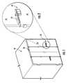
- FIG. 1is a pictorial view of an end of a shipping container with the door closed, and shows the position of an electronic seal lock module for locking the door; a container sensor electronics module on the container, and the position of a RF door seal;
- FIG. 2is an enlarged pictorial view of the electronic seal lock module shown in FIG. 1 ;
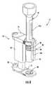
- FIG. 3is a pictorial view of a bolt-type seal lock having an improved bolt and locking body housing relative to the '300 patent application;
- FIG. 4is an exploded view of the seal lock shown in FIG. 3 ;
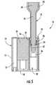
- FIG. 5is a cross-sectional view of the seal lock shown in FIGS. 3 and 4 ;
- FIG. 6is a view of the seal lock shown in FIGS. 3 , 4 and 5 , but with the outer surface of the locking body removed;
- FIG. 7is a pictorial view of the seal lock shown in FIGS. 3-6 , but with an ID tag and bolt exploded from the locking body;
- FIG. 8is a pictorial view of the entire electronic seal lock module shown in FIGS. 1 and 2 , and illustrates how the mechanical seal lock shown in FIGS. 3-7 is connected as a part to an electronics box to make an integrated electronic seal lock module;
- FIG. 9is a pictorial view of the electronic seal lock module, looking at the aft side relative to FIG. 8 ;
- FIG. 10is a cross-sectional view of the locking body portion of the seal bolt, and illustrates how the cut end of a bolt is pressed through the locking body;
- FIG. 11is similar to FIGS. 8-10 and illustrates how the cut end of a bolt is pushed through and dropped from the electronic seal lock module when a container is entered by an inspector;
- FIG. 12is an exploded view of the electronic seal lock module
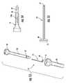
- FIG. 13is an exploded view of the bolt showing how an electronic serial number circuit is put on the bolt
- FIG. 14is a side view of the bolt
- FIG. 15is a side view of the electronic serial number circuit shown in FIG. 13 ;
- FIG. 16is a pictorial view that shows how the electronic serial number circuit shown in FIG. 13 is put into electrical contact with an electronics board in the electronic seal lock module;
- FIG. 17is an enlarged view of FIG. 16 and shows just the end of the bolt
- FIG. 18is similar to FIG. 1 , but shows the container door open to better illustrate the location of the container sensor electronics module;
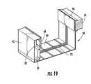
- FIG. 19is a pictorial view of the container sensor electronics module
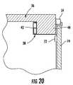
- FIG. 20is a sectional view of the shipping container shown in FIG. 1 , and shows the container sensor electronics module mounted to the container, and the position of the RF door seal on the container door relative to that electronics module, when the door is closed;
- FIG. 21is a side schematic of a cargo vessel that is loaded with containers
- FIG. 22is a schematic view of a networked system for keeping track of stacked containers on a cargo vessel or the like;
- FIG. 23is a schematic view that generally illustrates the sensing capability of the electronics module shown in FIG. 2 or FIG. 19 , and also generally illustrates the wireless link between the electronics seal lock module and the container sensor electronics module, and the wireless link between these components and a satellite uplink;
- FIG. 24is an alternative embodiment of just the bolt and locking body component of the electronic seal lock module.
- a seal lockthat is an improved version of the seal lock disclosed in the '300 application. Like the older one, the improved version 10 has a bolt 12 and a locking body 14 .
- the bolt 12is a hardened bolt, with further details of the bolt to be described below.
- the locking body 14 illustrated herehas a modified housing made from a single piece 15 of extruded aluminum (see FIG. 4 ).
- the housing 15may be other and better ways to manufacture the housing 15 for cost reasons, which may result in the housing being made from different materials.
- the specific method of manufacture and materials usedare not particularly relevant to the various components described here.
- the body 14has an end plate 16 on the upper side (see FIGS. 6 & 7 ) that receives the bolt 12 and a second end plate 18 on the opposite side.
- the second end plate 18may swivel about pivot 20 to allow access into the seal lock's housing 14 (see FIGS. 4 & 6 ).
- a metallic ID tagis used in the same way here as in the '300 application. However, in this instance, the ID tag 22 does not cover access to a locking spring inside the seal lock 10 . Instead, it simply provides a way for re-marking a serial number on the locking body 14 , when the seal bolt 10 is recycled (after the bolt 12 is cut) and a new serial number is needed for the corresponding serial number on the replacement bolt.
- the internal locking structurehas been altered relative to the '300 patent.
- the bolt 12is held in place by a snap ring 24 (see FIGS. 4 and 5 ).
- the snap ring 24is retained or held in place on one side by a hollow cylinder 26 and on the other side by a threaded plug 28 .
- the hollow cylinder 26is slipped or slid into the housing through a bore 30 and held in place by either press-fitting or gluing it permanently in place.
- the seal lock 10is refurbished by pressing the remnants of the bolt 12 past the snap ring 24 and out the bottom side of the housing, at 30 .
- the cylindrical bore 30provides a passageway from end-to-end through locking body 14 for this purpose.
- the ID tag 22is also replaced with a new one having a serial number that matches the replacement bolt.
- the ID tag 22slides into the housing 15 in the same way previously described in the '300 application. It might be held in place by a very low strength adhesive so that it does not fall from the housing prior to use.
- the bolt 12is inserted in the housing 15 and a shoulder 32 on the bolt (see FIG. 5 ) holds the ID tag 22 in place, in the same way previously described in the '300 patent application.
- the above designrepresents a departure from the '300 patent application in that it essentially enables the bolt portion of the seal lock 10 to be “recycled” by the person who cuts the lock, if desired.
- the shoulder 32is created by a plastic cover 33 that surrounds the hardened metal portion 35 of the bolt 12 (see FIG. 13 for example; and FIG. 5 ).
- the snap ring 24which prevents the bolt 12 from being pulled from the locking body 14 after insertion, will ride over the sloped part 37 of the bolt's end, as the end is pushed out through the bottom of the housing, as indicated at 30 .
- the bolt 12is obviously cut somewhere above that point, to sever the bolt's head 39 from the rest of the bolt.
- the userAfter the user removes the bolt 12 in the above way, all the user needs is a new bolt and ID tag to reinstall the seal lock 10 on the container.
- the usercan be provided with replacement packages of bolts and matching ID tags (the bolt and ID tag serial numbers matching, that is, as shown at 41 A and 41 B in FIG. 7 ), for the purpose of “recycling” the same seal lock 10 in a rail or shipping yard, or any other location where it is desired to open and then reseal a shipping container.
- the instant designalso provides a way to automatically identify when the bolt 12 is cut and/or to identify the serial number of the replacement bolt when it is installed. This will be described further below.
- the locking body's housing 15is enlarged slightly to carry a larger internal electronics module 34 (see FIGS. 4 and 5 , for example).
- the lock seal's electronics module 34may include a flash memory for data storage, in the same way previously described in the '300 application.
- the electronics moduleis further equipped with conventional wireless capability as an option, as schematically indicated at 35 in FIG. 23 .
- This type of functionalityis easy to implement via a standard 2.4 GHz modem that runs at low power levels.
- a power sourcewill be included with the electronics module 34 .
- Components like the electronics module 34are easy to obtain on a customized basis from companies like Cypress Semiconductor in San Jose, Calif.
- the mechanical bolt-type seal lock 10attaches to a cast aluminum housing 43 (which serves as an electronics box) that completes the entire electronic seal lock module (the complete electronic seal lock module is indicated generally at 45 in the various Figs.).
- the electronic seal lock module 45functions as the lock for a container door. How the electronics housing 43 connects to and integrates with the seal bolt 10 to create the overall electronic seal lock module 45 is best seen in FIGS. 8 and 9 , with an exploded view also being presented in FIG. 12 .
- the box 43contains an electronics board 47 powered by a battery pack 49 .
- the electronics board 47carries a wireless modem that enables the electronics seal lock module 45 to communicate with various other components of the system described here.
- the electronic seal lock module 45generally provides overall control and system functionality as will be described in additional detail below. It will have its own microprocessor based processing capability for handling sensor information and data of all kinds, which includes its own flash memory that is independent of any flash memory contained within the housing 15 of the locking body 14 (i.e., electronics module 34 ) on the bolt-seal 10 . All of these various components inside the electronic seal lock module 45 , including environmental sensors (temperature, humidity, impact or shock, etc.) can be placed on the electronics board 47 , inside housing 43 .
- the housing 43itself is made from two aluminum or plastic castings 51 , 53 that form a weathertight housing or box in which the electronics board 47 and batteries 49 are contained.
- the housing 43also carries permanent magnets 55 that connect the housing to the face of the container door 74 , just below the door's locking handle 73 (see FIGS. 1 and 2 ).
- the bolt portion 10 of the electronic seal lock module 45is free to rotate about a pin 57 relative to the weathertight box or housing 43 , so that the bolt 12 can be easily placed through corresponding holes in container door handle and related structures, all of which are conventional in design and would be familiar.
- the magnets 55then connect the module's housing 43 to the container door 74 so that it does not swing during container transport.
- the electronic seal lock's wireless capabilityis provided by two wireless antennas 59 and 61 that protrude from upper and lower sides of housing 43 . These antennas are integrated with the interior electronics board 47 (see FIG. 12 ).
- a set of wires(not shown in the figures) will extend from the electronics board 47 , through a sealed hole in the side of the housing 43 , and into a corresponding hole in the side of the seal lock body 14 .
- These wireswill terminate in two spring pin contacts 63 , 65 (see FIGS. 16 & 17 ) that reside just below the top part of the ID tag 22 when it is in position in lock body 14 . This location can be seen at 67 in FIG. 7 .
- These spring pin contacts 63 , 65are positioned so that, when the bolt 12 is inserted into the locking body 14 , they make electrical connection with two annular contact patches 69 , 71 on the end of the bolt (see FIGS. 16 & 17 ).
- the annular contact patches 69 , 71are made from a flexible circuit board material that is die cut into a shape to match the contour of the bolt 15 (see, generally, 75 in FIG. 15 ).
- the flexible circuit board 75is fabricated using common circuit board fabrication techniques with the two above mentioned annular contact patches 69 , 71 terminating in two circuit leads that traverse the length of the flexible circuit board 75 and are then bridged by a silicon microchip 77 .
- the silicon microchip 77electronically contains the serial number of the bolt 12 (see 41 in FIG. 14 ).
- the annular contact patches 69 , 71are placed on the exposed metallic end 79 of the bolt so they are not covered by the bolt's plastic cover 33 .
- the remaining part of the flexible circuit board 75 (and the microchip 77 )underlies the plastic cover such that it is not normally visible.
- Subsequent insertion of the bolt's end into the bolt's locking body 14brings the annular contact patches into electrical connection with the spring pin contacts 69 , 71 .
- FIG. 19An optional component of the system described here is a container sensor electronics module, generally indicated at 38 (see FIG. 19 ), which is mounted to the container 36 .
- This optional moduleis made from two aluminum extrusions 40 , 42 that are snap-fit together.
- the container sensor module 38is mounted to a cross-wise door beam 44 on the container (see FIG. 20 and is adhered by using a pressure sensitive adhesive (“PSA”) on surfaces 46 , 48 .
- PSApressure sensitive adhesive
- the unit 38is first installed on the container 36 , the PSA covering is removed from attachment surfaces 46 , 48 , and the extrusion is spread apart and placed on beam 44 . Releasing the extrusion causes spring forces to press the PSA into the door beam 44 .
- FIG. 20depicts a corner cross-section of the container 36 and door structure.
- the PSA-carrying surfaces 46 , 48are snap-fit to other parts of the electronics module 38 . This allows the module 38 to be disconnected from the container beam 44 , while leaving the surfaces 46 , 48 in place, so that the module 38 can later be remounted to the container. Removal of the module 38 from the container is necessary from time to time to replace the battery 52 , or to gain access to an electronics board module 52 and an antenna block 54 on opposite sides of the module 38 (see FIG. 19 ).
- This particular embodimentshows a single, exterior antenna block 54 .
- the container electronics module 38could be built with an interior antenna or both interior and exterior antennae, if desired.
- the battery pack 50is a typical two-cell battery pack that uses lithium cells capable of providing 3.6 volts output at 5000 milliamps.
- the electronics board module 52inside the container sensor module 38 , is a combination of electronics that includes specific sensors and digital data storage, similar to the seal electronics module 45 that locks the container door 74 . Therefore, and referring now to FIG. 23 , this electronics board 45 includes wireless transmission capability 56 (provided by a 2.4 GHz wireless modem—with the signal output via the antenna block 54 ), flash memory 58 for data storage (SM, typical), and humidity 60 , temperature 62 , and impact or vibration sensors 64 , for detecting these conditions inside the container 36 . It is to be appreciated that the electronic seal lock module 45 contains a similar set of sensors inside box 43 , for the purpose of sensing environmental conditions at the door on the outside of container 36 .
- the electronics board 52also has low power RF capability 66 for a door security sensor (explained further below), and may be modified to include still another sensor 68 that is capable of detecting changes in ambient light (i.e., daylight) inside the container. In other words, a change in interior lighting can be detected when the door is opened, under any circumstance, or if light should enter the container in some fashion because a hole is cut through a sidewall or roof.
- ambient lighti.e., daylight
- the type of electronics unit 52 just describedis available on a customized basis from companies like TeraHop Networks, Inc. in Alpharetta, Ga.
- the electronics board 52is connected to the antenna block 54 by a conventional ribbon cable 70 .
- the ribbon cableis protected by covering it with PSA or similar material, which is not shown in the drawings.
- the antenna block 54enables wireless data communication with a satellite uplink, or with a local area network, and also provides an RF link with an active RF door seal module 72 (see FIG. 18 ) mounted to the container door 74 .
- each electronic seal lock module 45 on a shipping container 36will be in wireless communication with the container sensor electronics module 38 mounted to the shipping container.
- the electronic seal lock module 45administrates the container sensor module described above, in preferred form (although it could be done the other way with the container module functioning as the administrator or the “master”), and stores shipping data, and stores and administrates other kinds of useful data a shipper may want or need. While data could be transmitted from any one of the three antenna sources described above (that is, the electronic seal lock 45 ; the sensor container module 38 ; and/or a third wireless antenna in the electronics module 34 inside the seal bolt's locking body 14 ), it is anticipated that the electronic seal lock 45 will provide the preferred transmission source.
- the antenna blocks 59 , 61in addition to transmitting data to a centralized database, via an uplink, also enable the electronic seal lock module 45 to communicate with the wireless modem 56 inside the container sensor module 38 . This enables virtually all of the data available in the electronic seal lock module 45 to be communicated to and exchanged with the container sensor module 38 on an ongoing basis.
- Shipping informationmay be easily downloaded from the seal lock 45 by a handheld device, and even via a USB port 76 on the locking body 14 , if desired, in essentially the same way as previously described in the '300 application, or by wireless transmission directly from the internal electronics inside the seal lock module 45 .
- the electronic seal lock module 45By combining the electronic seal lock module 45 as a component in a larger system that includes the container sensor module 38 , it expands upon the type of useful information that may be communicated and made accessible through the seal lock module 45 . It is important to understand that any of the data available in the electronic seal lock 45 is duplicated and resident in the container electronics module 38 , and it can be done in reciprocal fashion (data acquired by one device is shared with and duplicated by the other). This is important when a security breach arises. While there are different ways of entering a container, the simple fact of the matter is that both authorized and unauthorized container entry is usually accomplished by simply cutting the bolt 12 on the bolt lock 10 portion of the electronic seal module 45 .
- the seal lock module 45may be removed, as well.
- the containersubsequently arrives at the destination with clear evidence of tampering, but possibly with the entire module 45 missing (which means the electronic data stored in the seal lock is also missing).
- the thiefovertly attempts to destroy the container sensor electronics module 38 , then all of the necessary data will still remain resident with the container when it arrives and, as a consequence, can be downloaded. Not only can conventional shipping information be accessed to identify what is missing from the container relative to what should be there, but it would be possible to determine the time of entry and even the likely location.
- the antenna block 54 and 59 and 61 on these two container sensor and electronic seal lock modulesrespectively enable ongoing communication between each electronics module and a centralized data base provider, via the Internet or similar network.
- This mode of communicationis conventional and well-known. In the case of the typical ship that carries containers, the ship is likely to have uplink capability to a satellite. Therefore, if the master electronics module is in ongoing communication with a network, it would be possible to instantaneously transmit data at about the time the container door is opened or another type of unauthorized access is detected.
- FIG. 18shows a cross-section of the door 74 closed relative to a cross-section of the container 36 .
- the sensor electronics module 38can keep track of “when” and “for how long.”
- the container sensor electronics module 38is coded to the RF door seal 72 so that no other RF seal will give a correct response code to that particular electronics module 38 .
- the sensor electronics module 38is equipped with a reset or synchronization button (not shown in the drawings) that “reads” and synchronizes with electronic seal lock module 45 on the door.
- the seal lock housing 43can be provided with a flashing LED indicator that indicates all system components are linked wirelessly together. At that point, the bolt 12 may be installed on the container door.
- seal lock 10is installed on the container door 74
- the electronic serial number provided by the chip 17is recorded by both the electronic seal lock module 45 and the container sensor module 38 . This is to prevent tampering or replacement of the seal lock 10 during shipping.
- An advantage to the system described hereis that it provides an automatic update of serial numbers when new seal bolts are installed.
- Other advantagesinclude multiple redundancies and also a medium for communicating data from shipping containers that is unique.
- One type of redundancylies in using the electronic sensor module 45 as a data storage device with its own independent wireless transmission capability. This allows the container sensor module 38 to communicate with its respective seal lock module 45 on the container 36 , as described above, but it also enables seal lock modules to communicate with each other, if desired, when multiple numbers of the same type of seal lock are used on stacked containers.
- FIGS. 21 and 22it is known to communicate data wirelessly from cargo containers, trailers, railcars, etc.
- the metal walls of the groupmakes it difficult or impossible to transmit wireless data out through the ship's antenna 84 from those containers that are buried deeply within the stack.
- individual electronic seal lock modules 45constructed in the way described here, as communication nodes, or combine them into a nodal communication network as schematically illustrated in FIG. 22 .
- location and shipping datacan be passed through seal locks, from one to the next as needed, until the data is received and broadcast through the ship's antenna, or a satellite uplink 84 , to first a satellite 86 and then to a centralized data base 88 .
- a supply chain managercan locate all of the containers on a ship as needed, even if the container sought by the supply chain manager is covered by many other containers.
- FIG. 24shows further variations of the seal lock relative to the disclosure made in the '300 patent application.
- This Fig.shows a modified version of the seal lock 10 where the bolt 12 is replaced with a standard “U” shaped bolt that is found on padlocks.
- This variationworks in the same way, except that the locking body 14 is modified to have an opening 94 for receiving a pin 96 on the bolt 92 .
- the mechanical bolt partmay be modified in other ways as well.
- the bolt lock 10is described as having its own electronics module 34 . If this component is retained, then it creates a third redundant source for data storage, if desired. It may not be needed when the bolt lock design is integrated with the electronics box 43 described above. It is likely to be included if bolt locks 10 are supplied as independent devices and used in essentially the way they have been traditionally used—i.e., the manner described in the '300 application.
Landscapes
- Engineering & Computer Science (AREA)
- Computer Security & Cryptography (AREA)
- Physics & Mathematics (AREA)
- General Physics & Mathematics (AREA)
- Theoretical Computer Science (AREA)
- Lock And Its Accessories (AREA)
- Details Of Rigid Or Semi-Rigid Containers (AREA)
Abstract
Description
Claims (14)
Priority Applications (1)
| Application Number | Priority Date | Filing Date | Title |
|---|---|---|---|
| US12/347,613US7883126B2 (en) | 2005-07-29 | 2008-12-31 | Bolt-type seal lock having locking body pivotably connected to mounting component for attachment to shipping container door |
Applications Claiming Priority (3)
| Application Number | Priority Date | Filing Date | Title |
|---|---|---|---|
| US11/193,300US7438334B2 (en) | 2005-07-29 | 2005-07-29 | Bolt-type seal lock |
| US11/460,976US7828342B2 (en) | 2005-07-29 | 2006-07-29 | Reusable locking body, of bolt-type seal lock, having open-ended passageway and U-shaped bolt |
| US12/347,613US7883126B2 (en) | 2005-07-29 | 2008-12-31 | Bolt-type seal lock having locking body pivotably connected to mounting component for attachment to shipping container door |
Related Parent Applications (1)
| Application Number | Title | Priority Date | Filing Date |
|---|---|---|---|
| US11/460,976ContinuationUS7828342B2 (en) | 2005-07-29 | 2006-07-29 | Reusable locking body, of bolt-type seal lock, having open-ended passageway and U-shaped bolt |
Publications (2)
| Publication Number | Publication Date |
|---|---|
| US20090179437A1 US20090179437A1 (en) | 2009-07-16 |
| US7883126B2true US7883126B2 (en) | 2011-02-08 |
Family
ID=40135726
Family Applications (11)
| Application Number | Title | Priority Date | Filing Date |
|---|---|---|---|
| US11/460,976Expired - Fee RelatedUS7828342B2 (en) | 2005-07-29 | 2006-07-29 | Reusable locking body, of bolt-type seal lock, having open-ended passageway and U-shaped bolt |
| US12/347,594Expired - Fee RelatedUS7828343B2 (en) | 2005-07-29 | 2008-12-31 | Reusable locking body, of bolt-type seal lock, having open-ended passageway |
| US12/347,635Expired - Fee RelatedUS7900980B2 (en) | 2005-07-29 | 2008-12-31 | Locking body, of bolt-type seal lock, having electronics for detecting and wireless communicating cutting of bolt |
| US12/347,613Expired - Fee RelatedUS7883126B2 (en) | 2005-07-29 | 2008-12-31 | Bolt-type seal lock having locking body pivotably connected to mounting component for attachment to shipping container door |
| US12/347,714Expired - Fee RelatedUS7828346B2 (en) | 2005-07-29 | 2008-12-31 | Securing shipping container for transport |
| US12/347,684Expired - Fee RelatedUS7883127B2 (en) | 2005-07-29 | 2008-12-31 | Shipping container security system |
| US12/347,658Expired - Fee RelatedUS7938459B2 (en) | 2005-07-29 | 2008-12-31 | Bolt-type seal lock having locking body and separate mounting housing with electronics for wireless communications |
| US12/347,698Expired - Fee RelatedUS7828345B2 (en) | 2005-07-29 | 2008-12-31 | Shipping container security system including RF door alarm module |
| US12/347,723Expired - Fee RelatedUS7883128B2 (en) | 2005-07-29 | 2008-12-31 | Security system for shipping containers |
| US12/347,668Expired - Fee RelatedUS7828344B2 (en) | 2005-07-29 | 2008-12-31 | Bolt-type seal lock having separate housing, connected to locking body, with electronics for detecting and wireless communicating cutting of bolt |
| US12/774,627AbandonedUS20100214077A1 (en) | 2005-07-29 | 2010-05-05 | Reusable locking body, of bolt-type seal lock, having open-ended passageway and u-shaped bolt |
Family Applications Before (3)
| Application Number | Title | Priority Date | Filing Date |
|---|---|---|---|
| US11/460,976Expired - Fee RelatedUS7828342B2 (en) | 2005-07-29 | 2006-07-29 | Reusable locking body, of bolt-type seal lock, having open-ended passageway and U-shaped bolt |
| US12/347,594Expired - Fee RelatedUS7828343B2 (en) | 2005-07-29 | 2008-12-31 | Reusable locking body, of bolt-type seal lock, having open-ended passageway |
| US12/347,635Expired - Fee RelatedUS7900980B2 (en) | 2005-07-29 | 2008-12-31 | Locking body, of bolt-type seal lock, having electronics for detecting and wireless communicating cutting of bolt |
Family Applications After (7)
| Application Number | Title | Priority Date | Filing Date |
|---|---|---|---|
| US12/347,714Expired - Fee RelatedUS7828346B2 (en) | 2005-07-29 | 2008-12-31 | Securing shipping container for transport |
| US12/347,684Expired - Fee RelatedUS7883127B2 (en) | 2005-07-29 | 2008-12-31 | Shipping container security system |
| US12/347,658Expired - Fee RelatedUS7938459B2 (en) | 2005-07-29 | 2008-12-31 | Bolt-type seal lock having locking body and separate mounting housing with electronics for wireless communications |
| US12/347,698Expired - Fee RelatedUS7828345B2 (en) | 2005-07-29 | 2008-12-31 | Shipping container security system including RF door alarm module |
| US12/347,723Expired - Fee RelatedUS7883128B2 (en) | 2005-07-29 | 2008-12-31 | Security system for shipping containers |
| US12/347,668Expired - Fee RelatedUS7828344B2 (en) | 2005-07-29 | 2008-12-31 | Bolt-type seal lock having separate housing, connected to locking body, with electronics for detecting and wireless communicating cutting of bolt |
| US12/774,627AbandonedUS20100214077A1 (en) | 2005-07-29 | 2010-05-05 | Reusable locking body, of bolt-type seal lock, having open-ended passageway and u-shaped bolt |
Country Status (1)
| Country | Link |
|---|---|
| US (11) | US7828342B2 (en) |
Cited By (17)
| Publication number | Priority date | Publication date | Assignee | Title |
|---|---|---|---|---|
| US20100283578A1 (en)* | 2007-06-15 | 2010-11-11 | Matthew Henderson | Transponder Bolt Seal and a Housing for a Transponder |
| US9571986B2 (en) | 2014-05-07 | 2017-02-14 | Johnson Controls Technology Company | Systems and methods for detecting and using equipment location in a building management system |
| RU179998U1 (en)* | 2017-07-31 | 2018-05-30 | Антон Владимирович Кривошеев | SEAL WITH THE POSSIBILITY OF REMOTE CONTROL ITS STATE |
| US10481574B2 (en) | 2016-05-04 | 2019-11-19 | Johnson Controls Technology Company | Building alarm management system with mobile device notifications |
| US10941887B2 (en) | 2017-07-13 | 2021-03-09 | Mueller International Llc | Wide range coupling |
| US10982868B2 (en) | 2015-05-04 | 2021-04-20 | Johnson Controls Technology Company | HVAC equipment having locating systems and methods |
| US11131412B2 (en) | 2017-04-19 | 2021-09-28 | Mueller International, Llc | Joint restraint device |
| US11162621B2 (en) | 2019-02-04 | 2021-11-02 | Mueller International, Llc | Gland assembly |
| US11193609B2 (en) | 2018-02-28 | 2021-12-07 | Mueller International, Llc | Pipe coupling |
| US11199280B2 (en) | 2017-04-19 | 2021-12-14 | Mueller Intemational, LLC | Joint restraint device |
| US11215306B2 (en)* | 2017-04-19 | 2022-01-04 | Mueller International, Llc | Joint restraint device |
| US11306463B2 (en) | 2018-09-04 | 2022-04-19 | Mueller International, Llc | Hydrant shoe assembly |
| US11396964B2 (en) | 2017-04-19 | 2022-07-26 | Mueller International, Llc | Joint restraint device |
| US11396965B2 (en) | 2019-07-19 | 2022-07-26 | Mueller International, Llc | Restraint gripper cover with lockout breakaway |
| US11473705B2 (en) | 2018-08-22 | 2022-10-18 | Mueller International, Llc | Joint restraint device |
| US11654873B1 (en)* | 2019-11-07 | 2023-05-23 | AGA Tools & Products, Inc. | Park release apparatus and method of use |
| US11847940B2 (en) | 2021-04-23 | 2023-12-19 | J. J. Keller & Associates, Inc. | Bolt seal |
Families Citing this family (76)
| Publication number | Priority date | Publication date | Assignee | Title |
|---|---|---|---|---|
| US8280345B2 (en) | 2000-12-22 | 2012-10-02 | Google Inc. | LPRF device wake up using wireless tag |
| US20090016308A1 (en)* | 2000-12-22 | 2009-01-15 | Terahop Networks, Inc. | Antenna in cargo container monitoring and security system |
| US20080303897A1 (en)* | 2000-12-22 | 2008-12-11 | Terahop Networks, Inc. | Visually capturing and monitoring contents and events of cargo container |
| US7940716B2 (en) | 2005-07-01 | 2011-05-10 | Terahop Networks, Inc. | Maintaining information facilitating deterministic network routing |
| US8050625B2 (en) | 2000-12-22 | 2011-11-01 | Terahop Networks, Inc. | Wireless reader tags (WRTs) with sensor components in asset monitoring and tracking systems |
| US7142107B2 (en) | 2004-05-27 | 2006-11-28 | Lawrence Kates | Wireless sensor unit |
| US7616977B1 (en)* | 2005-01-28 | 2009-11-10 | Scott David Nortman | Method and apparatus for motorized control of an automobile radio cover |
| US20080143123A1 (en)* | 2005-05-31 | 2008-06-19 | Dewalch Norman Binz | Locking apparatus and method |
| US7828342B2 (en)* | 2005-07-29 | 2010-11-09 | Terahop Networks, Inc. | Reusable locking body, of bolt-type seal lock, having open-ended passageway and U-shaped bolt |
| US7438334B2 (en)* | 2005-07-29 | 2008-10-21 | Terry Daniel J | Bolt-type seal lock |
| DE102006025214B3 (en)* | 2006-05-29 | 2007-11-08 | Reel Reinheimer Elektronik Gmbh | Antenna arrangement for electromagnetic radiation, has antenna support fastened to inner side of container wall, where antenna extends into cavity through ventilation opening, and metal plate resting upon container wall |
| US8152367B2 (en)* | 2007-05-04 | 2012-04-10 | Sealed Air Corporation (Us) | Insulated container having a temperature monitoring device |
| US20090066503A1 (en)* | 2007-09-07 | 2009-03-12 | Lien-Feng Lin | System for monitoring containers with seals |
| US9472125B2 (en)* | 2007-10-05 | 2016-10-18 | E.J. Brooks Company | Reusable bolt electronic seal module with GPS/cellular phone communications and tracking system |
| US20090091144A1 (en)* | 2007-10-05 | 2009-04-09 | Robert Debrody | Bolt Security Seal with Reusable Electronics Module and Bolt |
| US8319640B2 (en)* | 2007-10-19 | 2012-11-27 | N7 Systems, Llc | Method for maintaining a shipping container manifest |
| US7884711B2 (en)* | 2007-12-15 | 2011-02-08 | Shanghai International Port (Group) Co., Ltd. | Container arrangement tag having positioning and electronic sealing function |
| US8031069B2 (en)* | 2008-01-14 | 2011-10-04 | Oded Yair Cohn | Electronic security seal and system |
| US8207848B2 (en) | 2008-05-16 | 2012-06-26 | Google Inc. | Locking system for shipping container including bolt seal and electronic device with arms for receiving bolt seal |
| WO2009151877A2 (en) | 2008-05-16 | 2009-12-17 | Terahop Networks, Inc. | Systems and apparatus for securing a container |
| EP2189964A1 (en)* | 2008-11-21 | 2010-05-26 | The European Community, represented by the European Commission | Sealing device |
| US8446278B2 (en)* | 2008-12-24 | 2013-05-21 | Innovative Labs Llc | Security monitor for doors |
| US8391435B2 (en) | 2008-12-25 | 2013-03-05 | Google Inc. | Receiver state estimation in a duty cycled radio |
| US9894410B2 (en) | 2009-06-09 | 2018-02-13 | The Directv Group, Inc. | Integrated satellite-TV broadband wireless system |
| US9160441B2 (en)* | 2009-06-09 | 2015-10-13 | The Directv Group, Inc. | Rotation pointed antenna for fixed wireless wide area networks |
| US8026792B2 (en)* | 2009-06-26 | 2011-09-27 | Cubic Corporation | Global asset tracking enterprise system |
| EP2372677B1 (en)* | 2010-03-29 | 2016-06-01 | Deutsche Post AG | A sealing system for sealing of doors of transport vehicles with door specific seals |
| US8963720B2 (en)* | 2010-05-11 | 2015-02-24 | The Boeing Company | RFID tag container |
| US10010213B2 (en)* | 2010-11-02 | 2018-07-03 | Ember Technologies, Inc. | Heated or cooled dishware and drinkware and food containers |
| US11950726B2 (en)* | 2010-11-02 | 2024-04-09 | Ember Technologies, Inc. | Drinkware container with active temperature control |
| US8508371B2 (en)* | 2010-11-16 | 2013-08-13 | Chung-Shan Institute Of Science And Technology | Multi-secured RFID electronic seal |
| US8797160B1 (en)* | 2011-01-06 | 2014-08-05 | Globaltrak, Llc | Apparatus for tamper proof security mechanism and tamper evident indicator |
| AU2012225535A1 (en) | 2011-03-08 | 2013-10-24 | Security Enhancement Systems, Llc | Lock |
| US20120227450A1 (en)* | 2011-03-08 | 2012-09-13 | Security Enhancement Systems, Llc | Lock |
| EP2568443B1 (en)* | 2011-09-07 | 2016-04-20 | National Chung-Shan Institute of Science and Technology | Electronic seal equipped with a breakage-detecting circuit and method for sealing a door based on the same |
| FI124681B (en)* | 2011-10-28 | 2014-12-15 | Abloy Oy | Padlock |
| WO2013134731A1 (en)* | 2012-03-09 | 2013-09-12 | Neology Inc. | Tamper evident cargo container seal bolt lock |
| US9121195B2 (en) | 2012-03-19 | 2015-09-01 | Neology, Inc. | Tamper evident cargo container seal bolt lock |
| EP2864141B1 (en)* | 2012-06-25 | 2017-11-15 | RSC Industries Inc. | Cooling system and methods for cooling interior volumes of cargo trailers |
| USD701444S1 (en)* | 2012-07-16 | 2014-03-25 | Neology, Inc. | Container seal |
| US8905318B2 (en)* | 2012-12-31 | 2014-12-09 | Chung Shan Institute Of Science And Technology, Armaments Bureau, M.N.D | Composite type multi-mode electronic seal |
| US9460593B2 (en) | 2013-03-14 | 2016-10-04 | Container Seal Project Partners, Llc | Container breach detector system |
| KR102038746B1 (en) | 2013-03-15 | 2019-10-30 | 스펙트럼 브랜즈, 인크. | Wireless lockset with integrated antenna, touch activation, and light communication device |
| CA2813285A1 (en) | 2013-04-18 | 2014-10-18 | Bluenica Corporation | Sensing device and method to monitor perishable goods |
| JP5453568B1 (en)* | 2013-11-25 | 2014-03-26 | 達哉 芦川 | OBD connector protective cover |
| USD756744S1 (en)* | 2014-05-27 | 2016-05-24 | Aesculap Ag | Container plumb with security bolt |
| US9508271B2 (en)* | 2014-12-12 | 2016-11-29 | Chih-Chuan Chen | Electronic bolt seal |
| US9911293B2 (en)* | 2015-01-12 | 2018-03-06 | Jonathan Lee | Security device for integration into a security system |
| US10553088B2 (en) | 2015-01-12 | 2020-02-04 | Jonathan Lee | Security device for integration into a security system |
| US10431401B2 (en)* | 2015-05-11 | 2019-10-01 | Brady Worldwide, Inc. | Lock out/tag out device having a tie-receiving passageway |
| US10089249B2 (en)* | 2015-08-13 | 2018-10-02 | Kyocera Document Solutions Inc. | In-package storing of data for an electronic device |
| US10109221B2 (en) | 2015-10-12 | 2018-10-23 | Evigia Systems, Inc. | Tamper-proof electronic bolt-seal |
| EP3403225A1 (en)* | 2016-01-15 | 2018-11-21 | Carrier Corporation | Data warehouse for a cold chain system |
| WO2017165349A1 (en) | 2016-03-22 | 2017-09-28 | Spectrum Brands, Inc. | Garage door opener with touch sensor authentication |
| EP3288038A1 (en) | 2016-08-26 | 2018-02-28 | The European Atomic Energy Community (EURATOM), represented by the European Commission | Sealing bolt, locking system and method of locking/unlocking |
| US11551498B2 (en)* | 2018-04-01 | 2023-01-10 | Joseph Hage | Locking system and method for a movable freight container door |
| DE102017107705A1 (en)* | 2017-04-10 | 2018-10-11 | Gemü Gebr. Müller Apparatebau Gmbh & Co. Kommanditgesellschaft | Device for arranging an electronic data carrier on a component of a fluid power system |
| CA3059726C (en)* | 2017-04-19 | 2021-07-27 | ASSA ABLOY Accessories and Door Controls Group, Inc. | Latch mechanism with engagement indicia |
| US11183086B2 (en)* | 2017-07-19 | 2021-11-23 | Globe Tracker, ApS | Wireless security for freight container seals |
| US11767692B2 (en) | 2017-11-09 | 2023-09-26 | Saf-Holland, Inc. | Vehicle door latch safety sensor arrangement |
| US11450158B2 (en) | 2018-01-05 | 2022-09-20 | Spectrum Brands, Inc. | Touch isolated electronic lock |
| US10629037B2 (en)* | 2018-04-24 | 2020-04-21 | International Business Machines Corporation | Smart lock intrusion detection |
| EP3803723A4 (en) | 2018-06-01 | 2022-03-09 | Stress Engineering Services, Inc. | SYSTEMS AND PROCEDURES FOR MONITORING, TRACKING AND TRACEBACK OF LOGISTICS |
| CN112770648A (en) | 2018-08-08 | 2021-05-07 | 跟踪包装有限公司 | Transport package tracking or monitoring system and method |
| US10510272B1 (en)* | 2018-08-10 | 2019-12-17 | Chih-Chuan Chen | Electronic seal improvement |
| US11214996B2 (en) | 2018-10-26 | 2022-01-04 | ASSA ABLOY Accessories and Door Controls Group, Inc. | Retrofit latch adapter |
| US11202335B2 (en)* | 2019-02-22 | 2021-12-14 | Nxgen Partners Ip, Llc | Combined tunneling and network management system |
| TWI669438B (en)* | 2019-03-15 | 2019-08-21 | 陳誌權 | Electronic seal improvement |
| TWI740236B (en)* | 2019-10-18 | 2021-09-21 | 關貿網路股份有限公司 | Electronic seal |
| US11922784B2 (en)* | 2020-05-08 | 2024-03-05 | Objectvideo Labs, Llc | Tamper detection using smart security fasteners |
| CN111572992B (en)* | 2020-05-28 | 2024-02-02 | 中国工商银行股份有限公司 | Accommodation apparatus, control method, and system for transporting article |
| US11988022B1 (en)* | 2021-09-16 | 2024-05-21 | The Government Of The United States As Represented By The Director, National Security Agency | Tamper evident computer housing lock |
| US12325567B2 (en) | 2021-11-11 | 2025-06-10 | Battelle Savannah River Alliance, Llc | Tamper-indicating device having robotic application features |
| US11773626B2 (en) | 2022-02-15 | 2023-10-03 | Stress Engineering Services, Inc. | Systems and methods for facilitating logistics |
| TWI837609B (en)* | 2022-03-11 | 2024-04-01 | 辰晧電子股份有限公司 | Electronic seal with a passive rfid chip , rfid reader and rfid system |
| US12422458B2 (en)* | 2023-09-18 | 2025-09-23 | Yms Tech Co., Ltd. | Electronic seal device for electronic meter and smart electronic seal system including the same |
Citations (55)
| Publication number | Priority date | Publication date | Assignee | Title |
|---|---|---|---|---|
| US4567740A (en)* | 1981-12-04 | 1986-02-04 | Kelly Eamonn W J | Locking devices |
| US4750197A (en) | 1986-11-10 | 1988-06-07 | Denekamp Mark L | Integrated cargo security system |
| US4802700A (en)* | 1987-11-09 | 1989-02-07 | Trans-Guard Industries, Inc. | Locking seal |
| US4826027A (en) | 1985-02-28 | 1989-05-02 | Tally Safe Systems Ab | Seal |
| US5005883A (en) | 1990-05-24 | 1991-04-09 | E. J. Brooks Company | Tamper indicator for a locking seal |
| US5097253A (en) | 1989-01-06 | 1992-03-17 | Battelle Memorial Institute | Electronic security device |
| US5127687A (en) | 1990-10-17 | 1992-07-07 | E. J. Brooks Co. | Tamper indicator for a locking seal |
| US5615247A (en) | 1994-10-11 | 1997-03-25 | Mills; Thomas O. | Security device for the protection of cargo transport containers |
| US5656996A (en) | 1996-03-13 | 1997-08-12 | Global Associates, Ltd. | Electronic security bonding device |
| US5732989A (en) | 1996-06-14 | 1998-03-31 | Transgaurd Industries, Inc. | Lock and tool therefor |
| US5761935A (en)* | 1997-07-30 | 1998-06-09 | Emhart Inc. | Weatherproof padlock |
| US5857721A (en) | 1997-02-18 | 1999-01-12 | Liroff; Jeff | Cargo seal |
| US5878604A (en) | 1997-08-11 | 1999-03-09 | Transguard Industries | Protection device for bolt seal and hasp |
| US6166627A (en) | 1999-07-20 | 2000-12-26 | Reeley; Ronald B. | Mobile detection and alert system |
| US6265973B1 (en)* | 1999-04-16 | 2001-07-24 | Transguard Industries, Inc. | Electronic security seal |
| US6339397B1 (en) | 2000-06-01 | 2002-01-15 | Lat-Lon, Llc | Portable self-contained tracking unit and GPS tracking system |
| US6407666B1 (en) | 2001-07-10 | 2002-06-18 | Transguard Industries, Inc. | Electrical connector for a cylindrical member |
| US20020074811A1 (en) | 2000-07-03 | 2002-06-20 | Rainer Kuenzel | Bolt seal |
| US6420971B1 (en) | 1999-06-23 | 2002-07-16 | Tripseal Limited | Electronic seal, methods and security system |
| US6464269B1 (en)* | 2001-02-27 | 2002-10-15 | Richard E. Wilhelm | Security seal and removal tool |
| US6467316B1 (en)* | 2000-08-24 | 2002-10-22 | Waterson Chen | Protective sleeve for a padlock |
| US6536815B1 (en) | 2001-01-16 | 2003-03-25 | Jeffrey Howard Liroff | Tamper evident cargo seal |
| US20030189491A1 (en) | 2001-07-13 | 2003-10-09 | Ng Sing King | Circuit and method for electronic security seal |
| WO2003095773A1 (en) | 2002-05-13 | 2003-11-20 | European Community | Multipurpose seal with lock |
| US20040041705A1 (en)* | 2002-08-27 | 2004-03-04 | Hi-G-Tek Ltd. | Smart container monitoring system |
| US20040100379A1 (en)* | 2002-09-17 | 2004-05-27 | Hans Boman | Method and system for monitoring containers to maintain the security thereof |
| US6747558B1 (en)* | 2001-11-09 | 2004-06-08 | Savi Technology, Inc. | Method and apparatus for providing container security with a tag |
| US20040113783A1 (en)* | 2002-12-11 | 2004-06-17 | Millennium Information Systems, Llc | Container integrity management system |
| US20040119588A1 (en) | 2001-05-02 | 2004-06-24 | Marks Roger Julian | Door mountable alarm system |
| US6813914B2 (en)* | 2002-09-23 | 2004-11-09 | Min-Hui Chen | Protective mechanism for padlock |
| US6870476B2 (en)* | 2003-04-07 | 2005-03-22 | Bulldog Technologies Inc. | Continuous feedback container security system |
| US20050073406A1 (en) | 2003-09-03 | 2005-04-07 | Easley Linda G. | System and method for providing container security |
| US6882274B2 (en)* | 2001-05-02 | 2005-04-19 | Northrop Grumman Corporation | Energy conserving satellite tracking tag |
| US20050088299A1 (en) | 2003-10-24 | 2005-04-28 | Bandy William R. | Radio frequency identification (RFID) based sensor networks |
| US20050128080A1 (en) | 2003-02-21 | 2005-06-16 | Hall Larry L. | Cargo lock and monitoring apparatus and process |
| US6932629B2 (en)* | 2003-11-05 | 2005-08-23 | Kabushiki Kaisha Toshiba | Device with USB terminal |
| US20050212671A1 (en) | 2002-08-27 | 2005-09-29 | Micha Auerbach | Smart container monitoring system |
| US20050219037A1 (en) | 2004-04-02 | 2005-10-06 | Tao Huang | Cargo theft prevention method and system |
| US20060158326A1 (en) | 2004-12-10 | 2006-07-20 | Easley Linda G | System and method for fusion of container tracking data |
| US20060164232A1 (en) | 2003-04-09 | 2006-07-27 | Visible Assets, Inc. | Auditable security for cargo containers and other repositories |
| US20060170560A1 (en) | 2002-12-11 | 2006-08-03 | Hi-G-Tek Ltd. | Tamper-resistant electronic seal |
| US20060202824A1 (en)* | 2005-02-04 | 2006-09-14 | Container Security Inc. | Electronic seal and method of shipping container tracking |
| US7148800B2 (en) | 2004-05-03 | 2006-12-12 | Transport International Pool, Inc. | Method for associating an asset with a monitoring device |
| US20070032951A1 (en) | 2005-04-19 | 2007-02-08 | Jaymart Sensors, Llc | Miniaturized Inertial Measurement Unit and Associated Methods |
| US20070069528A1 (en)* | 2005-09-29 | 2007-03-29 | Rainer Kuenzel | Cable Seal With Re-Usable Body |
| US7209037B2 (en) | 2003-06-17 | 2007-04-24 | Infraegis, Inc. | System and method for monitoring a security of an asset |
| US7239238B2 (en) | 2004-03-30 | 2007-07-03 | E. J. Brooks Company | Electronic security seal |
| US7283052B2 (en)* | 2005-05-13 | 2007-10-16 | Commerceguard Ab | Method and system for arming a multi-layered security system |
| US7333015B2 (en) | 2004-03-24 | 2008-02-19 | Commerceguard Ab | Method and system for monitoring containers to maintain the security thereof |
| US7339469B2 (en) | 2004-11-22 | 2008-03-04 | Maersk Logistics Usa, Inc. | Shipping container monitoring and tracking system |
| US7360806B2 (en) | 2004-01-21 | 2008-04-22 | Henry Kong Sun Ching | Methods and apparatus for facilitating security and tamper control |
| US7382251B2 (en) | 2004-04-07 | 2008-06-03 | Commerceguard Ab | Method and system for arming a container security device without use of electronic reader |
| US20080315596A1 (en) | 2005-07-29 | 2008-12-25 | Terry Daniel J | Shipping Container Security System |
| US7472933B2 (en)* | 2004-12-16 | 2009-01-06 | Itw Limited | Security seal |
| US20090026773A1 (en) | 2005-07-29 | 2009-01-29 | Terahop Networks, Inc. | Bolt-type seal with usb interface for use with shipping containers |
Family Cites Families (87)
| Publication number | Priority date | Publication date | Assignee | Title |
|---|---|---|---|---|
| US3805265A (en)* | 1971-10-06 | 1974-04-16 | Rcds Enterprises Inc | Radiant wave locating system |
| US3945671A (en)* | 1974-10-23 | 1976-03-23 | Emhart Corporation | Seal lock and the like incorporating permanently secured single engagement |
| US4275385A (en)* | 1979-08-13 | 1981-06-23 | Bell Telephone Laboratories, Incorporated | Infrared personnel locator system |
| US4446454A (en)* | 1981-01-21 | 1984-05-01 | Pyle Ronald E | Home security system |
| US4613990A (en)* | 1984-06-25 | 1986-09-23 | At&T Bell Laboratories | Radiotelephone transmission power control |
| CA1246681A (en)* | 1985-01-30 | 1988-12-13 | Northern Telecom Limited | Terminal address assignment in a broadcast transmission system |
| US4688244A (en)* | 1986-11-10 | 1987-08-18 | Marwan Hannon | Integrated cargo security system |
| US4817537A (en)* | 1987-03-16 | 1989-04-04 | Cripe Alan R | Container carrying convertible rail-highway vehicle |
| US5425051A (en)* | 1992-11-09 | 1995-06-13 | Norand Corporation | Radio frequency communication network having adaptive parameters |
| US5117501A (en)* | 1988-08-08 | 1992-05-26 | General Electric Company | Dynamic regrouping in a trunked radio communications system |
| US4895999A (en)* | 1988-09-19 | 1990-01-23 | Calderon Bill R | Protective safety enclosure for electrical outlets |
| JPH0773385B2 (en)* | 1989-04-03 | 1995-08-02 | 三菱電機株式会社 | Mobile phone equipment |
| GB8910997D0 (en)* | 1989-05-12 | 1989-06-28 | Tunstall Telecom Ltd | Radio transmission system |
| US5042181A (en)* | 1990-01-17 | 1991-08-27 | Thomas & Betts Corporation | Cable tie identification tag |
| US6006100A (en)* | 1990-05-25 | 1999-12-21 | Norand Corporation | Multi-level, hierarchical radio-frequency communication system |
| US5682379A (en)* | 1993-12-23 | 1997-10-28 | Norand Corporation | Wireless personal local area network |
| US5805807A (en)* | 1990-05-25 | 1998-09-08 | Norand Corporation | Multilevel data communication system including local and host systems |
| US5640151A (en)* | 1990-06-15 | 1997-06-17 | Texas Instruments Incorporated | Communication system for communicating with tags |
| US5040238A (en)* | 1990-06-29 | 1991-08-13 | Motorola, Inc. | Trunking system communication resource reuse method |
| JPH0470584A (en)* | 1990-07-11 | 1992-03-05 | Mitsubishi Electric Corp | satellite navigation equipment |
| US5120097A (en)* | 1990-07-30 | 1992-06-09 | The Rel Corporation | Security seal |
| US5206903A (en)* | 1990-12-26 | 1993-04-27 | At&T Bell Laboratories | Automatic call distribution based on matching required skills with agents skills |
| JPH04369492A (en)* | 1991-06-18 | 1992-12-22 | Pioneer Electron Corp | Gps position measurement device |
| US5401946A (en)* | 1991-07-22 | 1995-03-28 | Weinblatt; Lee S. | Technique for correlating purchasing behavior of a consumer to advertisements |
| ZA925728B (en)* | 1991-08-01 | 1993-04-28 | City Communications Ltd | Improvements in a radio communication system |
| CA2120520A1 (en)* | 1991-10-01 | 1993-04-15 | Robert C. Meier | A radio frequency local area network |
| US5974236A (en)* | 1992-03-25 | 1999-10-26 | Aes Corporation | Dynamically reconfigurable communications network and method |
| US5558013A (en)* | 1992-05-07 | 1996-09-24 | Blackstone, Jr.; James O. | Device and method for electronically measuring the fullness of a trash receptacle |
| JP2798557B2 (en)* | 1992-06-19 | 1998-09-17 | シャープ株式会社 | Track display device for navigation system |
| WO1994006087A1 (en)* | 1992-09-01 | 1994-03-17 | Nuttall David J H | Information model based on a physical system |
| US5543778A (en)* | 1993-04-19 | 1996-08-06 | Code-Alarm, Inc. | Security system |
| US5790946A (en)* | 1993-07-15 | 1998-08-04 | Rotzoll; Robert R. | Wake up device for a communications system |
| US5442758A (en)* | 1993-07-19 | 1995-08-15 | Sequent Computer Systems, Inc. | Apparatus and method for achieving reduced overhead mutual exclusion and maintaining coherency in a multiprocessor system utilizing execution history and thread monitoring |
| US5331637A (en)* | 1993-07-30 | 1994-07-19 | Bell Communications Research, Inc. | Multicast routing using core based trees |
| DE4329898A1 (en)* | 1993-09-04 | 1995-04-06 | Marcus Dr Besson | Wireless medical diagnostic and monitoring device |
| US5555376A (en)* | 1993-12-03 | 1996-09-10 | Xerox Corporation | Method for granting a user request having locational and contextual attributes consistent with user policies for devices having locational attributes consistent with the user request |
| CA2135856A1 (en)* | 1993-12-10 | 1995-06-11 | Steven Peter Allen | Low power, addressable data communication device and method |
| JP2974274B2 (en)* | 1994-05-12 | 1999-11-10 | エヌ・ティ・ティ移動通信網株式会社 | Transmission power control method and transmission power control device |
| US5461390A (en)* | 1994-05-27 | 1995-10-24 | At&T Ipm Corp. | Locator device useful for house arrest and stalker detection |
| US5579306A (en)* | 1994-09-01 | 1996-11-26 | Ericsson Inc. | Time and frequency slot allocation system and method |
| US5550547A (en)* | 1994-09-12 | 1996-08-27 | International Business Machines Corporation | Multiple item radio frequency tag identification protocol |
| US5565858A (en)* | 1994-09-14 | 1996-10-15 | Northrop Grumman Corporation | Electronic inventory system for stacked containers |
| US5511232A (en)* | 1994-12-02 | 1996-04-23 | Motorola, Inc. | Method for providing autonomous radio talk group configuration |
| US5596652A (en)* | 1995-03-23 | 1997-01-21 | Portable Data Technologies, Inc. | System and method for accounting for personnel at a site and system and method for providing personnel with information about an emergency site |
| US5793882A (en)* | 1995-03-23 | 1998-08-11 | Portable Data Technologies, Inc. | System and method for accounting for personnel at a site and system and method for providing personnel with information about an emergency site |
| ZA959074B (en)* | 1995-04-12 | 1996-05-22 | Lo Jack Corp | Vehicle tracking transponder system and transponding method |
| US5577029A (en)* | 1995-05-04 | 1996-11-19 | Interwave Communications | Cellular communication network having intelligent switching nodes |
| RU95107478A (en)* | 1995-05-18 | 1997-02-10 | А.И. Грушин | Method for removal of most insignificant digits in computations with floating point |
| US6097707A (en)* | 1995-05-19 | 2000-08-01 | Hodzic; Migdat I. | Adaptive digital wireless communications network apparatus and process |
| US5950124A (en)* | 1995-09-06 | 1999-09-07 | Telxon Corporation | Cellular communication system with dynamically modified data transmission parameters |
| US5833910A (en)* | 1995-10-03 | 1998-11-10 | Mecanismos Auxiliares Industiales S.A. | Mold and method for manufacturing conduit grommet elements |
| US5933354A (en)* | 1995-10-13 | 1999-08-03 | Matsushita Electric Industrial Co., Ltd. | System for controlling physical distribution pallets |
| US6005884A (en)* | 1995-11-06 | 1999-12-21 | Ems Technologies, Inc. | Distributed architecture for a wireless data communications system |
| US6039365A (en)* | 1996-01-26 | 2000-03-21 | Rogatnev; Nikolai Timofeevich | Seal-locking mechanism |
| US6069563A (en)* | 1996-03-05 | 2000-05-30 | Kadner; Steven P. | Seal system |
| US5652751A (en)* | 1996-03-26 | 1997-07-29 | Hazeltine Corporation | Architecture for mobile radio networks with dynamically changing topology using virtual subnets |
| US5850187A (en)* | 1996-03-27 | 1998-12-15 | Amtech Corporation | Integrated electronic tag reader and wireless communication link |
| JP2803626B2 (en)* | 1996-04-05 | 1998-09-24 | 日本電気株式会社 | Transmission power control method for mobile radio terminals |
| US5881366A (en)* | 1996-05-01 | 1999-03-09 | Logitech, Inc. | Wireless peripheral interface |
| US6058374A (en)* | 1996-06-20 | 2000-05-02 | Northrop Grumman Corporation | Inventorying method and system for monitoring items using tags |
| US5917433A (en)* | 1996-06-26 | 1999-06-29 | Orbital Sciences Corporation | Asset monitoring system and associated method |
| US5959568A (en)* | 1996-06-26 | 1999-09-28 | Par Goverment Systems Corporation | Measuring distance |
| US5892441A (en)* | 1996-06-26 | 1999-04-06 | Par Government Systems Corporation | Sensing with active electronic tags |
| US5907491A (en)* | 1996-08-23 | 1999-05-25 | Csi Technology, Inc. | Wireless machine monitoring and communication system |
| US6201974B1 (en)* | 1996-09-06 | 2001-03-13 | Nokia Mobile Phones Limited | Mobile station and network having hierarchical index for cell broadcast service |
| US5950133A (en)* | 1996-11-05 | 1999-09-07 | Lockheed Martin Corporation | Adaptive communication network |
| US5890054A (en)* | 1996-11-14 | 1999-03-30 | Telxon Corporation | Emergency mobile routing protocol |
| JP3097581B2 (en)* | 1996-12-27 | 2000-10-10 | 日本電気株式会社 | Ad-hoc local area network configuration method, communication method and terminal |
| US5977913A (en)* | 1997-02-07 | 1999-11-02 | Dominion Wireless | Method and apparatus for tracking and locating personnel |
| CA2207371A1 (en)* | 1997-06-09 | 1998-12-09 | Andre Gagnon | Apparatus for monitoring opening of sealed containers |
| US5963134A (en)* | 1997-07-24 | 1999-10-05 | Checkpoint Systems, Inc. | Inventory system using articles with RFID tags |
| US6072784A (en)* | 1997-07-25 | 2000-06-06 | At&T Corp. | CDMA mobile station wireless transmission power management with adaptive scheduling priorities based on battery power level |
| KR100284257B1 (en)* | 1997-08-31 | 2001-03-02 | 윤종용 | Automatic starting device of electronic toll collection system |
| US6091724A (en)* | 1997-11-20 | 2000-07-18 | International Business Machines Corporation | Routing messages within a network using the data content of the message |
| US6104512A (en)* | 1998-01-23 | 2000-08-15 | Motorola, Inc. | Method for adjusting the power level of an infrared signal |
| US5936527A (en)* | 1998-02-10 | 1999-08-10 | E-Tag Systems, Inc. | Method and apparatus for locating and tracking documents and other objects |
| KR100291413B1 (en)* | 1998-03-02 | 2001-07-12 | 김영환 | Transmission power control device of mobile communication terminal |
| EP1118011B1 (en)* | 1998-09-03 | 2008-11-05 | Wherenet, Inc. | Network for multi-lateration with circularly polarized antenna |
| US6084512A (en)* | 1998-10-02 | 2000-07-04 | Lucent Technologies, Inc. | Method and apparatus for electronic labeling and localizing |
| US6154658A (en)* | 1998-12-14 | 2000-11-28 | Lockheed Martin Corporation | Vehicle information and safety control system |
| US6246882B1 (en)* | 1998-12-22 | 2001-06-12 | Telefonaktiebolaget Lm Ericsson (Publ) | Wide area item tracking system |
| US6256303B1 (en)* | 1999-10-15 | 2001-07-03 | Akoo, Inc. | Wireless broadcast link to remote receiver |
| US7270353B2 (en)* | 2003-02-24 | 2007-09-18 | The European Community | Multiple transponder seal device |
| US20040215532A1 (en)* | 2003-02-25 | 2004-10-28 | Hans Boman | Method and system for monitoring relative movement of maritime containers and other cargo |
| US7595727B2 (en)* | 2003-05-16 | 2009-09-29 | Information Systems Laboratories, Inc. | Frangible electronic sealing security system |
| US7012520B2 (en)* | 2003-06-17 | 2006-03-14 | Infraegis, Inc. | Global intelligent remote detection system |
| US7538672B2 (en)* | 2005-11-01 | 2009-05-26 | Savi Technology, Inc. | Method and apparatus for capacitive sensing of door position |
- 2006
- 2006-07-29USUS11/460,976patent/US7828342B2/ennot_activeExpired - Fee Related
- 2008
- 2008-12-31USUS12/347,594patent/US7828343B2/ennot_activeExpired - Fee Related
- 2008-12-31USUS12/347,635patent/US7900980B2/ennot_activeExpired - Fee Related
- 2008-12-31USUS12/347,613patent/US7883126B2/ennot_activeExpired - Fee Related
- 2008-12-31USUS12/347,714patent/US7828346B2/ennot_activeExpired - Fee Related
- 2008-12-31USUS12/347,684patent/US7883127B2/ennot_activeExpired - Fee Related
- 2008-12-31USUS12/347,658patent/US7938459B2/ennot_activeExpired - Fee Related
- 2008-12-31USUS12/347,698patent/US7828345B2/ennot_activeExpired - Fee Related
- 2008-12-31USUS12/347,723patent/US7883128B2/ennot_activeExpired - Fee Related
- 2008-12-31USUS12/347,668patent/US7828344B2/ennot_activeExpired - Fee Related
- 2010
- 2010-05-05USUS12/774,627patent/US20100214077A1/ennot_activeAbandoned
Patent Citations (59)
| Publication number | Priority date | Publication date | Assignee | Title |
|---|---|---|---|---|
| US4567740A (en)* | 1981-12-04 | 1986-02-04 | Kelly Eamonn W J | Locking devices |
| US4826027A (en) | 1985-02-28 | 1989-05-02 | Tally Safe Systems Ab | Seal |
| US4750197A (en) | 1986-11-10 | 1988-06-07 | Denekamp Mark L | Integrated cargo security system |
| US4802700B1 (en)* | 1987-11-09 | 1996-10-01 | Transguard Ind Inc | Locking seal |
| US4802700A (en)* | 1987-11-09 | 1989-02-07 | Trans-Guard Industries, Inc. | Locking seal |
| US5097253A (en) | 1989-01-06 | 1992-03-17 | Battelle Memorial Institute | Electronic security device |
| US5005883A (en) | 1990-05-24 | 1991-04-09 | E. J. Brooks Company | Tamper indicator for a locking seal |
| US5127687A (en) | 1990-10-17 | 1992-07-07 | E. J. Brooks Co. | Tamper indicator for a locking seal |
| US5615247A (en) | 1994-10-11 | 1997-03-25 | Mills; Thomas O. | Security device for the protection of cargo transport containers |
| US5656996A (en) | 1996-03-13 | 1997-08-12 | Global Associates, Ltd. | Electronic security bonding device |
| US5732989A (en) | 1996-06-14 | 1998-03-31 | Transgaurd Industries, Inc. | Lock and tool therefor |
| US5857721A (en) | 1997-02-18 | 1999-01-12 | Liroff; Jeff | Cargo seal |
| US5761935A (en)* | 1997-07-30 | 1998-06-09 | Emhart Inc. | Weatherproof padlock |
| US5878604A (en) | 1997-08-11 | 1999-03-09 | Transguard Industries | Protection device for bolt seal and hasp |
| US6009731A (en) | 1997-08-11 | 2000-01-04 | Transguard Industries, Inc. | Locking device for door keeper bar |
| US6265973B1 (en)* | 1999-04-16 | 2001-07-24 | Transguard Industries, Inc. | Electronic security seal |
| US6420971B1 (en) | 1999-06-23 | 2002-07-16 | Tripseal Limited | Electronic seal, methods and security system |
| US6166627A (en) | 1999-07-20 | 2000-12-26 | Reeley; Ronald B. | Mobile detection and alert system |
| US6339397B1 (en) | 2000-06-01 | 2002-01-15 | Lat-Lon, Llc | Portable self-contained tracking unit and GPS tracking system |
| US20020074811A1 (en) | 2000-07-03 | 2002-06-20 | Rainer Kuenzel | Bolt seal |
| US6467316B1 (en)* | 2000-08-24 | 2002-10-22 | Waterson Chen | Protective sleeve for a padlock |
| US6536815B1 (en) | 2001-01-16 | 2003-03-25 | Jeffrey Howard Liroff | Tamper evident cargo seal |
| US6464269B1 (en)* | 2001-02-27 | 2002-10-15 | Richard E. Wilhelm | Security seal and removal tool |
| US6882274B2 (en)* | 2001-05-02 | 2005-04-19 | Northrop Grumman Corporation | Energy conserving satellite tracking tag |
| US20040119588A1 (en) | 2001-05-02 | 2004-06-24 | Marks Roger Julian | Door mountable alarm system |
| US6407666B1 (en) | 2001-07-10 | 2002-06-18 | Transguard Industries, Inc. | Electrical connector for a cylindrical member |
| US20030189491A1 (en) | 2001-07-13 | 2003-10-09 | Ng Sing King | Circuit and method for electronic security seal |
| US6747558B1 (en)* | 2001-11-09 | 2004-06-08 | Savi Technology, Inc. | Method and apparatus for providing container security with a tag |
| US7178369B2 (en) | 2002-05-13 | 2007-02-20 | European Community | Multi-purpose seal with lock |
| WO2003095773A1 (en) | 2002-05-13 | 2003-11-20 | European Community | Multipurpose seal with lock |
| US20040041705A1 (en)* | 2002-08-27 | 2004-03-04 | Hi-G-Tek Ltd. | Smart container monitoring system |
| US20050212671A1 (en) | 2002-08-27 | 2005-09-29 | Micha Auerbach | Smart container monitoring system |
| US20040100379A1 (en)* | 2002-09-17 | 2004-05-27 | Hans Boman | Method and system for monitoring containers to maintain the security thereof |
| US6813914B2 (en)* | 2002-09-23 | 2004-11-09 | Min-Hui Chen | Protective mechanism for padlock |
| US20040113783A1 (en)* | 2002-12-11 | 2004-06-17 | Millennium Information Systems, Llc | Container integrity management system |
| US20060170560A1 (en) | 2002-12-11 | 2006-08-03 | Hi-G-Tek Ltd. | Tamper-resistant electronic seal |
| US20050128080A1 (en) | 2003-02-21 | 2005-06-16 | Hall Larry L. | Cargo lock and monitoring apparatus and process |
| US6870476B2 (en)* | 2003-04-07 | 2005-03-22 | Bulldog Technologies Inc. | Continuous feedback container security system |
| US20060164232A1 (en) | 2003-04-09 | 2006-07-27 | Visible Assets, Inc. | Auditable security for cargo containers and other repositories |
| US7209037B2 (en) | 2003-06-17 | 2007-04-24 | Infraegis, Inc. | System and method for monitoring a security of an asset |
| US20050073406A1 (en) | 2003-09-03 | 2005-04-07 | Easley Linda G. | System and method for providing container security |
| US20050088299A1 (en) | 2003-10-24 | 2005-04-28 | Bandy William R. | Radio frequency identification (RFID) based sensor networks |
| US6932629B2 (en)* | 2003-11-05 | 2005-08-23 | Kabushiki Kaisha Toshiba | Device with USB terminal |
| US7360806B2 (en) | 2004-01-21 | 2008-04-22 | Henry Kong Sun Ching | Methods and apparatus for facilitating security and tamper control |
| US7333015B2 (en) | 2004-03-24 | 2008-02-19 | Commerceguard Ab | Method and system for monitoring containers to maintain the security thereof |
| US7239238B2 (en) | 2004-03-30 | 2007-07-03 | E. J. Brooks Company | Electronic security seal |
| US20050219037A1 (en) | 2004-04-02 | 2005-10-06 | Tao Huang | Cargo theft prevention method and system |
| US7382251B2 (en) | 2004-04-07 | 2008-06-03 | Commerceguard Ab | Method and system for arming a container security device without use of electronic reader |
| US7148800B2 (en) | 2004-05-03 | 2006-12-12 | Transport International Pool, Inc. | Method for associating an asset with a monitoring device |
| US7339469B2 (en) | 2004-11-22 | 2008-03-04 | Maersk Logistics Usa, Inc. | Shipping container monitoring and tracking system |
| US20080094209A1 (en)* | 2004-11-22 | 2008-04-24 | Maersk Logistics Usa, Inc. | Shipping container monitoring and tracking system |
| US20060158326A1 (en) | 2004-12-10 | 2006-07-20 | Easley Linda G | System and method for fusion of container tracking data |
| US7472933B2 (en)* | 2004-12-16 | 2009-01-06 | Itw Limited | Security seal |
| US20060202824A1 (en)* | 2005-02-04 | 2006-09-14 | Container Security Inc. | Electronic seal and method of shipping container tracking |
| US20070032951A1 (en) | 2005-04-19 | 2007-02-08 | Jaymart Sensors, Llc | Miniaturized Inertial Measurement Unit and Associated Methods |
| US7283052B2 (en)* | 2005-05-13 | 2007-10-16 | Commerceguard Ab | Method and system for arming a multi-layered security system |
| US20080315596A1 (en) | 2005-07-29 | 2008-12-25 | Terry Daniel J | Shipping Container Security System |
| US20090026773A1 (en) | 2005-07-29 | 2009-01-29 | Terahop Networks, Inc. | Bolt-type seal with usb interface for use with shipping containers |
| US20070069528A1 (en)* | 2005-09-29 | 2007-03-29 | Rainer Kuenzel | Cable Seal With Re-Usable Body |
Non-Patent Citations (2)
| Title |
|---|
| Information Disclosure Statement (IDS) Letter Regarding Common Patent Application(s) submitted May 7, 2009. |
| Information Disclosure Statement (IDS) Letter Regarding Common Patent Application(s), submitted by Applicant on Mar. 23, 2010. |
Cited By (24)
| Publication number | Priority date | Publication date | Assignee | Title |
|---|---|---|---|---|
| US20100283578A1 (en)* | 2007-06-15 | 2010-11-11 | Matthew Henderson | Transponder Bolt Seal and a Housing for a Transponder |
| US9571986B2 (en) | 2014-05-07 | 2017-02-14 | Johnson Controls Technology Company | Systems and methods for detecting and using equipment location in a building management system |
| US10982868B2 (en) | 2015-05-04 | 2021-04-20 | Johnson Controls Technology Company | HVAC equipment having locating systems and methods |
| US10481574B2 (en) | 2016-05-04 | 2019-11-19 | Johnson Controls Technology Company | Building alarm management system with mobile device notifications |
| US11313504B2 (en) | 2017-04-19 | 2022-04-26 | Mueller International, Llc | Joint restraint device |
| US11396964B2 (en) | 2017-04-19 | 2022-07-26 | Mueller International, Llc | Joint restraint device |
| US11131412B2 (en) | 2017-04-19 | 2021-09-28 | Mueller International, Llc | Joint restraint device |
| US11906082B2 (en) | 2017-04-19 | 2024-02-20 | Mueller International, Llc | Joint restraint device |
| US11796103B2 (en) | 2017-04-19 | 2023-10-24 | Mueller International, Llc | Joint restraint device |
| US11199280B2 (en) | 2017-04-19 | 2021-12-14 | Mueller Intemational, LLC | Joint restraint device |
| US11215306B2 (en)* | 2017-04-19 | 2022-01-04 | Mueller International, Llc | Joint restraint device |
| US11435015B2 (en) | 2017-04-19 | 2022-09-06 | Mueller International, Llc | Joint restraint device |
| US10941887B2 (en) | 2017-07-13 | 2021-03-09 | Mueller International Llc | Wide range coupling |
| US12031647B2 (en) | 2017-07-13 | 2024-07-09 | Mueller International, Llc | Wide range coupling |
| RU179998U1 (en)* | 2017-07-31 | 2018-05-30 | Антон Владимирович Кривошеев | SEAL WITH THE POSSIBILITY OF REMOTE CONTROL ITS STATE |
| US11193609B2 (en) | 2018-02-28 | 2021-12-07 | Mueller International, Llc | Pipe coupling |
| US11473705B2 (en) | 2018-08-22 | 2022-10-18 | Mueller International, Llc | Joint restraint device |
| US11306463B2 (en) | 2018-09-04 | 2022-04-19 | Mueller International, Llc | Hydrant shoe assembly |
| US11668416B2 (en) | 2019-02-04 | 2023-06-06 | Mueller International, Llc | Gland assembly |
| US11162621B2 (en) | 2019-02-04 | 2021-11-02 | Mueller International, Llc | Gland assembly |
| US11396965B2 (en) | 2019-07-19 | 2022-07-26 | Mueller International, Llc | Restraint gripper cover with lockout breakaway |
| US11654873B1 (en)* | 2019-11-07 | 2023-05-23 | AGA Tools & Products, Inc. | Park release apparatus and method of use |
| US11847940B2 (en) | 2021-04-23 | 2023-12-19 | J. J. Keller & Associates, Inc. | Bolt seal |
| US12249256B2 (en) | 2021-04-23 | 2025-03-11 | J.J. Keller & Associates, Inc. | Bolt seal |
Also Published As
| Publication number | Publication date |
|---|---|
| US20090127873A1 (en) | 2009-05-21 |
| US20090146437A1 (en) | 2009-06-11 |
| US20090179437A1 (en) | 2009-07-16 |
| US20090115202A1 (en) | 2009-05-07 |
| US7828345B2 (en) | 2010-11-09 |
| US7828346B2 (en) | 2010-11-09 |
| US7883127B2 (en) | 2011-02-08 |
| US20090108596A1 (en) | 2009-04-30 |
| US20090115200A1 (en) | 2009-05-07 |
| US20080315596A1 (en) | 2008-12-25 |
| US7828344B2 (en) | 2010-11-09 |
| US20090108597A1 (en) | 2009-04-30 |
| US20090126424A1 (en) | 2009-05-21 |
| US7828343B2 (en) | 2010-11-09 |
| US7883128B2 (en) | 2011-02-08 |
| US7938459B2 (en) | 2011-05-10 |
| US7828342B2 (en) | 2010-11-09 |
| US20090115201A1 (en) | 2009-05-07 |
| US20100214077A1 (en) | 2010-08-26 |
| US7900980B2 (en) | 2011-03-08 |
Similar Documents
| Publication | Publication Date | Title |
|---|---|---|
| US7883126B2 (en) | Bolt-type seal lock having locking body pivotably connected to mounting component for attachment to shipping container door | |
| US20200105167A1 (en) | Reusable bolt electronic seal module with gps/cellular phone communications & tracking system | |
| CN1906643B (en) | Method and system for monitoring containers to maintain the security thereof | |
| US7564350B2 (en) | Method and system for monitoring containers to maintain the security thereof | |
| US20050046567A1 (en) | Method and system for utilizing multiple sensors for monitoring container security, contents and condition | |
| EP2909819B1 (en) | Security devices | |
| CN101529483B (en) | Sensor arrangement for securing the loads of containers | |
| WO2004104768A2 (en) | Method and system for utilizing multiple sensors for monitoring container security, contents and condition | |
| KR101044442B1 (en) | Switch sensor based container security system | |
| CN112930546B (en) | Tracking Devices |
Legal Events
| Date | Code | Title | Description |
|---|---|---|---|
| STCF | Information on status: patent grant | Free format text:PATENTED CASE | |
| AS | Assignment | Owner name:TERAHOP NETWORKS, INC., GEORGIA Free format text:ASSIGNMENT OF ASSIGNORS INTEREST;ASSIGNORS:DAN TERRY & ASSOCIATES, INC.;INTELLI-QUE, LLC;TERRY, DANIEL J.;AND OTHERS;REEL/FRAME:027238/0868 Effective date:20080925 | |
| AS | Assignment | Owner name:KLJ CONSULTING LLC, WASHINGTON Free format text:ASSIGNMENT OF ASSIGNORS INTEREST;ASSIGNOR:TERAHOP NETWORKS, INC.;REEL/FRAME:027422/0740 Effective date:20110916 | |
| AS | Assignment | Owner name:GOOGLE INC., CALIFORNIA Free format text:ASSIGNMENT OF ASSIGNORS INTEREST;ASSIGNOR:KLJ CONSULTING LLC;REEL/FRAME:028100/0701 Effective date:20120323 | |
| FPAY | Fee payment | Year of fee payment:4 | |
| AS | Assignment | Owner name:GOOGLE LLC, CALIFORNIA Free format text:CHANGE OF NAME;ASSIGNOR:GOOGLE INC.;REEL/FRAME:044101/0405 Effective date:20170929 | |
| MAFP | Maintenance fee payment | Free format text:PAYMENT OF MAINTENANCE FEE, 8TH YR, SMALL ENTITY (ORIGINAL EVENT CODE: M2552) Year of fee payment:8 | |
| FEPP | Fee payment procedure | Free format text:MAINTENANCE FEE REMINDER MAILED (ORIGINAL EVENT CODE: REM.); ENTITY STATUS OF PATENT OWNER: SMALL ENTITY | |
| LAPS | Lapse for failure to pay maintenance fees | Free format text:PATENT EXPIRED FOR FAILURE TO PAY MAINTENANCE FEES (ORIGINAL EVENT CODE: EXP.); ENTITY STATUS OF PATENT OWNER: SMALL ENTITY | |
| STCH | Information on status: patent discontinuation | Free format text:PATENT EXPIRED DUE TO NONPAYMENT OF MAINTENANCE FEES UNDER 37 CFR 1.362 | |
| FP | Lapsed due to failure to pay maintenance fee | Effective date:20230208 |