US7883031B2 - Ophthalmic drug delivery system - Google Patents
Ophthalmic drug delivery systemDownload PDFInfo
- Publication number
- US7883031B2 US7883031B2US10/851,611US85161104AUS7883031B2US 7883031 B2US7883031 B2US 7883031B2US 85161104 AUS85161104 AUS 85161104AUS 7883031 B2US7883031 B2US 7883031B2
- Authority
- US
- United States
- Prior art keywords
- ophthalmic fluid
- ophthalmic
- eye
- fluid
- discharge plate
- Prior art date
- Legal status (The legal status is an assumption and is not a legal conclusion. Google has not performed a legal analysis and makes no representation as to the accuracy of the status listed.)
- Expired - Lifetime, expires
Links
Images


Classifications
- B—PERFORMING OPERATIONS; TRANSPORTING
- B05—SPRAYING OR ATOMISING IN GENERAL; APPLYING FLUENT MATERIALS TO SURFACES, IN GENERAL
- B05B—SPRAYING APPARATUS; ATOMISING APPARATUS; NOZZLES
- B05B17/00—Apparatus for spraying or atomising liquids or other fluent materials, not covered by the preceding groups
- B05B17/04—Apparatus for spraying or atomising liquids or other fluent materials, not covered by the preceding groups operating with special methods
- B05B17/06—Apparatus for spraying or atomising liquids or other fluent materials, not covered by the preceding groups operating with special methods using ultrasonic or other kinds of vibrations
- B05B17/0607—Apparatus for spraying or atomising liquids or other fluent materials, not covered by the preceding groups operating with special methods using ultrasonic or other kinds of vibrations generated by electrical means, e.g. piezoelectric transducers
- B05B17/0638—Apparatus for spraying or atomising liquids or other fluent materials, not covered by the preceding groups operating with special methods using ultrasonic or other kinds of vibrations generated by electrical means, e.g. piezoelectric transducers spray being produced by discharging the liquid or other fluent material through a plate comprising a plurality of orifices
- B05B17/0646—Vibrating plates, i.e. plates being directly subjected to the vibrations, e.g. having a piezoelectric transducer attached thereto
- A—HUMAN NECESSITIES
- A61—MEDICAL OR VETERINARY SCIENCE; HYGIENE
- A61M—DEVICES FOR INTRODUCING MEDIA INTO, OR ONTO, THE BODY; DEVICES FOR TRANSDUCING BODY MEDIA OR FOR TAKING MEDIA FROM THE BODY; DEVICES FOR PRODUCING OR ENDING SLEEP OR STUPOR
- A61M11/00—Sprayers or atomisers specially adapted for therapeutic purposes
- A61M11/005—Sprayers or atomisers specially adapted for therapeutic purposes using ultrasonics
- A—HUMAN NECESSITIES
- A61—MEDICAL OR VETERINARY SCIENCE; HYGIENE
- A61M—DEVICES FOR INTRODUCING MEDIA INTO, OR ONTO, THE BODY; DEVICES FOR TRANSDUCING BODY MEDIA OR FOR TAKING MEDIA FROM THE BODY; DEVICES FOR PRODUCING OR ENDING SLEEP OR STUPOR
- A61M11/00—Sprayers or atomisers specially adapted for therapeutic purposes
- A61M11/04—Sprayers or atomisers specially adapted for therapeutic purposes operated by the vapour pressure of the liquid to be sprayed or atomised
- A61M11/041—Sprayers or atomisers specially adapted for therapeutic purposes operated by the vapour pressure of the liquid to be sprayed or atomised using heaters
- A61M11/042—Sprayers or atomisers specially adapted for therapeutic purposes operated by the vapour pressure of the liquid to be sprayed or atomised using heaters electrical
- B—PERFORMING OPERATIONS; TRANSPORTING
- B05—SPRAYING OR ATOMISING IN GENERAL; APPLYING FLUENT MATERIALS TO SURFACES, IN GENERAL
- B05B—SPRAYING APPARATUS; ATOMISING APPARATUS; NOZZLES
- B05B17/00—Apparatus for spraying or atomising liquids or other fluent materials, not covered by the preceding groups
- B05B17/04—Apparatus for spraying or atomising liquids or other fluent materials, not covered by the preceding groups operating with special methods
- B05B17/06—Apparatus for spraying or atomising liquids or other fluent materials, not covered by the preceding groups operating with special methods using ultrasonic or other kinds of vibrations
- B05B17/0607—Apparatus for spraying or atomising liquids or other fluent materials, not covered by the preceding groups operating with special methods using ultrasonic or other kinds of vibrations generated by electrical means, e.g. piezoelectric transducers
- B05B17/0623—Apparatus for spraying or atomising liquids or other fluent materials, not covered by the preceding groups operating with special methods using ultrasonic or other kinds of vibrations generated by electrical means, e.g. piezoelectric transducers coupled with a vibrating horn
- B—PERFORMING OPERATIONS; TRANSPORTING
- B05—SPRAYING OR ATOMISING IN GENERAL; APPLYING FLUENT MATERIALS TO SURFACES, IN GENERAL
- B05B—SPRAYING APPARATUS; ATOMISING APPARATUS; NOZZLES
- B05B17/00—Apparatus for spraying or atomising liquids or other fluent materials, not covered by the preceding groups
- B05B17/04—Apparatus for spraying or atomising liquids or other fluent materials, not covered by the preceding groups operating with special methods
- B05B17/06—Apparatus for spraying or atomising liquids or other fluent materials, not covered by the preceding groups operating with special methods using ultrasonic or other kinds of vibrations
- B05B17/0607—Apparatus for spraying or atomising liquids or other fluent materials, not covered by the preceding groups operating with special methods using ultrasonic or other kinds of vibrations generated by electrical means, e.g. piezoelectric transducers
- B05B17/0653—Details
- B05B17/0676—Feeding means
- A—HUMAN NECESSITIES
- A61—MEDICAL OR VETERINARY SCIENCE; HYGIENE
- A61F—FILTERS IMPLANTABLE INTO BLOOD VESSELS; PROSTHESES; DEVICES PROVIDING PATENCY TO, OR PREVENTING COLLAPSING OF, TUBULAR STRUCTURES OF THE BODY, e.g. STENTS; ORTHOPAEDIC, NURSING OR CONTRACEPTIVE DEVICES; FOMENTATION; TREATMENT OR PROTECTION OF EYES OR EARS; BANDAGES, DRESSINGS OR ABSORBENT PADS; FIRST-AID KITS
- A61F9/00—Methods or devices for treatment of the eyes; Devices for putting in contact-lenses; Devices to correct squinting; Apparatus to guide the blind; Protective devices for the eyes, carried on the body or in the hand
- A61F9/0008—Introducing ophthalmic products into the ocular cavity or retaining products therein
- A—HUMAN NECESSITIES
- A61—MEDICAL OR VETERINARY SCIENCE; HYGIENE
- A61M—DEVICES FOR INTRODUCING MEDIA INTO, OR ONTO, THE BODY; DEVICES FOR TRANSDUCING BODY MEDIA OR FOR TAKING MEDIA FROM THE BODY; DEVICES FOR PRODUCING OR ENDING SLEEP OR STUPOR
- A61M11/00—Sprayers or atomisers specially adapted for therapeutic purposes
- A61M11/06—Sprayers or atomisers specially adapted for therapeutic purposes of the injector type
- A61M11/065—Sprayers or atomisers specially adapted for therapeutic purposes of the injector type using steam as driving gas
- A—HUMAN NECESSITIES
- A61—MEDICAL OR VETERINARY SCIENCE; HYGIENE
- A61M—DEVICES FOR INTRODUCING MEDIA INTO, OR ONTO, THE BODY; DEVICES FOR TRANSDUCING BODY MEDIA OR FOR TAKING MEDIA FROM THE BODY; DEVICES FOR PRODUCING OR ENDING SLEEP OR STUPOR
- A61M2205/00—General characteristics of the apparatus
- A61M2205/59—Aesthetic features, e.g. distraction means to prevent fears of child patients
- A—HUMAN NECESSITIES
- A61—MEDICAL OR VETERINARY SCIENCE; HYGIENE
- A61M—DEVICES FOR INTRODUCING MEDIA INTO, OR ONTO, THE BODY; DEVICES FOR TRANSDUCING BODY MEDIA OR FOR TAKING MEDIA FROM THE BODY; DEVICES FOR PRODUCING OR ENDING SLEEP OR STUPOR
- A61M2210/00—Anatomical parts of the body
- A61M2210/06—Head
- A61M2210/0612—Eyes
Definitions
- the present inventionrelates to drug delivery devices for dispensing liquid as an aerosol or atomized mist and, more particularly, for dispensing medicaments to the eye.
- the ophthalmic literatureis rife with references to the need for a better means of ophthalmic drug delivery. With an estimate of 25 million users of eye drops in the United States alone, the magnitude of the public health issue is considerable. Accordingly, a new means of ophthalmic drug delivery is needed.
- an ophthalmic medication spray dispenserincludes the following: great ease of use; can be used in any “attitude” (i.e. with patient sitting, erect, lying down, head tilted back, etc.); abbreviated treatment cycle as compared to eye drop usage; improved bioavailability/efficacy; improved safety (reduced local and systemic side effects); improved sterility; increased compliance due to ease of use and “alert” systems; possibility of singular efficacy in the treatment of certain vision threatening infections; conservation of material (reduced volume, diminished waste/loss); and system (fixation target to help ensure proper application).
- the present inventionprovides a fluid atomizer comprising a body having a proximal end and a distal end.
- a removable reservoiris connected to the body, wherein the reservoir contains a fluid disposed therein.
- a discharge plateis disposed at the distal end, wherein the discharge plate includes a plurality of openings extending therethrough.
- the atomizerfurther comprises propulsion means for transmitting the fluid from the reservoir to the discharge plate and through the plurality of openings, wherein transmission of the fluid through the plurality of openings atomizes the fluid.
- the atomizeralso includes a system controller electronically connected to the propulsion means, wherein the system controller controls operation of the propulsion means.
- the present inventionprovides a fluid atomizer comprising a body having a proximal end and a distal end.
- a removable reservoiris connected to the body, wherein the reservoir contains a fluid disposed therein.
- a discharge plateis disposed at the distal end, wherein the discharge plate includes a plurality of openings extending therethrough.
- the atomizerfurther comprises propulsion means for transmitting the fluid from the reservoir to the discharge plate and through the plurality of openings, wherein transmission of the fluid through the plurality of openings atomizes the fluid.
- the atomizeralso includes a means for spacing the discharge plate a predetermined distance from a target.
- the present inventionprovides a fluid atomizer comprising a body having a proximal end and a distal end.
- a removable reservoiris connected to the body, wherein the reservoir contains a fluid disposed therein.
- a discharge plateis disposed at the distal end, wherein the discharge plate includes a plurality of openings extending therethrough.
- the atomizerfurther comprises propulsion means for transmitting the fluid from the reservoir to the discharge plate and through the plurality of openings, wherein transmission of the fluid through the plurality of openings atomizes the fluid.
- the atomizeralso includes a system controller electronically connected to the propulsion means, wherein the system controller controls operation of the propulsion means.
- the atomizeralso includes a means for adjusting operation of the propulsion means to adjust an amount of the fluid transmitted across the discharge plate, wherein the means for adjusting operation of the propulsion means are operatively connected to the system controller.
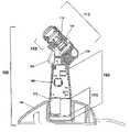
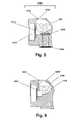
- FIG. 1is a side elevational view, partially broken away, of a mist spraying device according to a first embodiment of the present invention.
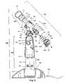
- FIG. 2is an exploded view of the device of FIG. 1 .
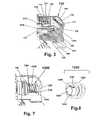
- FIG. 3is an enlarged side profile view of a first embodiment of a fluid reservoir connected to the device.
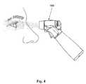
- FIG. 4is a side profile view showing the device being used to spray a mist into a patient's eye.
- FIG. 5is a side profile view of the first embodiment of the fluid reservoir shown in FIG. 3 , having been removed from the device.
- FIG. 6is an enlarged side profile view of a second embodiment of a fluid reservoir.
- FIG. 7is an enlarged side profile view of a third embodiment of a fluid reservoir.
- FIG. 8is a perspective view of the reservoir of FIG. 7 .
- FIG. 9is an enlarged side view, in section, of a prime mover inserted into the device.
- FIG. 10is an enlarged exploded perspective view of a nozzle assembly of the device.
- FIG. 11is an enlarged side view, in section, of the nozzle assembly of the device.
- FIG. 12 ais an enlarged partial sectional view of a first embodiment of the mesh plate of the nozzle assembly.
- FIG. 12 bis an enlarged partial sectional view of a second embodiment of the mesh plate of the nozzle assembly.
- FIG. 12 cis an enlarged partial sectional view of a third embodiment of the mesh plate of the nozzle assembly.
- FIG. 12 dis an enlarged partial sectional view of a fourth embodiment of the mesh plate of the nozzle assembly.
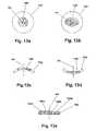
- FIG. 13 ais a top plan view of a first embodiment of a mesh plate.
- FIG. 13 bis a top plan view of a second embodiment of a mesh plate.
- FIG. 13 cis a side view, in section of a third embodiment of a mesh plate.
- FIG. 13 dis a side view, in section, of a fourth embodiment of a mesh plate.
- FIG. 13 eis an enlarged partial sectional view of a fifth embodiment of a mesh plate.
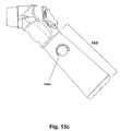
- FIG. 14is a perspective view of the device showing an optional dosage adjustment feature.
- FIG. 15 ais a perspective view of the device showing a first embodiment of the dosage adjustment feature.
- FIG. 15 bis a perspective view of the device showing a second embodiment of the dosage adjustment feature.
- FIG. 15 cis a perspective view of the device showing a third embodiment of the dosage adjustment feature.
- FIG. 16is a top plan view showing the targeting device of FIG. 14 .
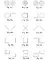
- FIG. 17 ais a schematic view of a first embodiment of a targeting mechanism showing the device too close to the target.
- FIG. 17 bis a schematic view of the first embodiment of the targeting mechanism showing the device a correct distance from the target.
- FIG. 17 cis a schematic view of the first embodiment of the targeting mechanism showing the device too far from the target.
- FIG. 18 ais a schematic view of a second embodiment of a targeting mechanism showing the device too close to the target.
- FIG. 18 bis a schematic view of the second embodiment of the targeting mechanism showing the device a correct distance from the target.
- FIG. 18 cis a schematic view of the second embodiment of the targeting mechanism showing the device too far from the target.
- FIG. 19 ais a schematic view of a third embodiment of a targeting mechanism showing the device too close to the target.
- FIG. 19 bis a schematic view of the third embodiment of the targeting mechanism showing the device a correct distance from the target.
- FIG. 19 cis a schematic view of the third embodiment of the targeting mechanism showing the device too far from the target.
- FIG. 20 ais a schematic view of a fourth embodiment of a targeting mechanism showing the device too close to the target.
- FIG. 20 bis a schematic view of the fourth embodiment of the targeting mechanism showing the device a correct distance from the target.
- FIG. 20 cis a schematic view of the fourth embodiment of the targeting mechanism showing the device too far from the target.
- FIG. 21 ais a schematic view of a fifth embodiment of a targeting mechanism showing the device too close to the target.
- FIG. 21 bis a schematic view of the fifth embodiment of the targeting mechanism showing the device a correct distance from the target.
- FIG. 21 cis a schematic view of the fifth embodiment of the targeting mechanism showing the device too far from the target.
- FIG. 22 ais a side elevational view of a mechanical targeting device according to the present invention.
- FIG. 22 bis a top plan view of a proximal end of the mechanical targeting device shown in FIG. 22 a , being used on a patient.
- FIG. 23is a schematic view of an electronic control system for the device.
- FIG. 24is a perspective view of an alternative embodiment of the device according to the present invention.
- FIG. 25is a perspective view of another alternative embodiment of the device according to the present invention.
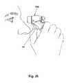
- FIG. 26is a perspective view showing self-administration of medication using the device.
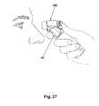
- FIG. 27is a perspective view showing administration of medication by one person to another using the device.
- distalis meant to mean the discharge end of the inventive device and the term “proximal” is meant to mean the end of the inventive device held by user.
- proximalis meant to mean the end of the inventive device held by user.
- the terminologyincludes the words above specifically mentioned, derivatives thereof and words of similar import.
- the embodiments illustrated beloware not intended to be exhaustive or to limit the invention to the precise form disclosed. These embodiments are chosen and described to best explain the principle of the invention and its application and practical use and to enable others skilled in the art to best utilize the invention.
- the present inventionprovides a novel device and method for ophthalmic drug delivery.
- the present inventionprovides a small, hand-held, battery or AC powered device that nebulizes liquid eye medications into a fine mist.
- the mist from the deviceis directed at the eye to be treated and the drug is delivered via the mist.
- a preferred means of forming the mistis by ultrasound energy generated by a piezoelectric transducer or other suitable piezo device.
- a small plume of nebulized solutionis generated, consisting of particles measuring what is believed to be an average of about five microns in diameter.
- the volume of each emissionis dependent on the rate of mist generation (typically measured in micro liters per second) as well as the duration of the operation of the device, which may be easily varied by using an electronic control circuit.
- the shape, dimensions and focus of the emitted mistare proportioned for delivery to the human eye.
- the momentum of the mistis subliminal to the ocular blink and lacrimation reflexes and may also create a soothing sensation in the eye.
- the deviceis equally efficient when used in any “attitude” from a natural, upright head posture to leaning forward or lying back. Application time is significantly abbreviated compared to eye drop usage, which typically requires several maneuvers and careful attention to detail to ensure proper administration.
- FIGS. 1 and 2show a hand held device 100 that directs a mist of drug to an eye for treatment.
- the device 100includes a vial or reservoir 120 of the fluid to be delivered to the eye, such as a drug.
- the userholds the device 100 and, by operating an activation switch, causes the device 100 to generate a mist of the liquid, which is discharged from the head portion 110 of the device 100 .
- the usersimply aims the head of the device at the target eye to allow the mist to contact the eye.
- the componentsinclude a head portion 110 and a handle portion 160 .
- the head portion 110preferably contains, from a proximal to a distal direction, a fluid reservoir 120 to retain a fluid 122 to be administered, a body 130 that houses a prime mover 140 to draw the fluid from the reservoir 120 and propel the fluid 122 out the distal end of the device 100 , and a nozzle assembly 150 which aerosolizes the fluid 122 and to form a mist pattern of the fluid 122 as the fluid 122 is directed toward its target.
- the handle portion 160preferably contains the power source 170 , such as a battery, an activation switch 180 to activate the device, and a system controller 190 that controls the various operational aspects of the device 100 .
- the head portion 110includes the body 130 that connects the reservoir 120 , the prime mover 140 , and the nozzle assembly 150 together.
- the head portion 110is connected to the handle portion 160 and provides a conduit for electrical leads (not shown) extending from the reservoir 120 and the prime mover 140 to the system controller 190 .
- the fluid reservoir 120may can be a vial pre-filled with the fluid 122 to be delivered to the eye.
- the reservoir 120may incorporate a scale comprising a clear window 123 with volume graduation markings 124 to indicate fill level or doses of fluid 122 remaining in the reservoir 120 .
- the scaleis read with the device 100 standing on its base 166 , as shown in FIG. 1 .
- the reservoir 120is preferably shaped to maintain contact with the prime mover 140 when the device 100 is held in a preferred operational orientation while spraying into an eye (as shown in FIG. 4 ), or is tilted in any direction within 45 degrees of horizontal.
- the reservoir 120is preferably further shaped to maximize the percentage of the total fill volume that is actually dispensed.
- the reservoir 120houses the fluid 122 that is used to form the aerosolized mist when the device 100 is operated.
- the reservoir 120is preferably a removable and replaceable cartridge 126 that is securably connectable to the body 130 so that the reservoir 120 does not accidentally readily separate from the body 120 , yet is easily replaceable when the reservoir 120 is empty or when a reservoir 120 containing a different type of fluid is desired to be connected to the device 100 .
- the reservoir 120includes an engagement surface 128 disposed proximate to an upper and a lower side of the reservoir 120 .
- the engagement surface 128slides over a corresponding extension in the body 130 , as shown in FIG. 3 , so that the reservoir 120 is retained onto the body 130 with a frictional fit.
- the extensionincludes a plurality of seals, such as o-rings 134 , that provide a sealing engagement between the reservoir 120 and the body 130 and assists in frictionally retaining the body 120 to the reservoir 130 .
- the reservoir 120may connect with the body 130 by other means known to those skilled in the art, including, but not limited to, threaded connections, bayonet fittings, or other suitable means.
- the reservoir 120includes an open face 1210 that is covered by an air impermeable seal 1212 .
- the open face 1210allows the fluid 122 to be deposited into the reservoir 120 , and then sealed with the seal 1212 .
- a seal 1212may be constructed from thin gauge aluminum, or some other suitable material, with a biocompatible coating disposed on both faces of the seal 1212 .
- the seal 1212is attached to the reservoir 120 with a biocompatible adhesive.
- the seal 1212is designed to maintain sterility of the fluid 122 within the reservoir 120 , yet be able to be easily punctured by the proximal end 142 of the prime mover 140 upon connecting the reservoir 120 to the body 130 so that the fluid 122 in the reservoir 120 is put into fluid communication with the proximal end 142 of the prime mover 140 , as shown in FIG. 3 .
- a vent 1214is formed in the wall of the reservoir 120 , preferably proximate to the top of the reservoir 120 , to allow air to be drawn into the reservoir 120 to compensate for the loss volume of fluid 122 as the fluid 122 is drawn out of the reservoir 120 due to operation of the device 100 .
- a filter 1216covers the vent 1214 to allow ambient air into the interior of the reservoir 120 , but prevents fluid 122 in the reservoir 120 from leaking out of the vent 1214 . While a presently preferred embodiment of the reservoir 120 envisions the fluid 122 to be prepackaged in the reservoir 120 , those skilled in the art will recognize that the reservoir 120 may also be refillable, such as through the vent 1214 .
- an alternate embodiment of a reservoir 1218may have a collapsible bladder 1220 that collapses under vacuum as the fluid 122 is drawn out of the reservoir 1218 during operation of the device 100 , without any air being able to enter the reservoir 122 .
- the bladder 1220is preferably supple, biocompatible, and bondable.
- the bladder 1220is constructed of aluminum film coated on both sides with a polymer resin.
- the bladder 1220is approximately 0.025 to 0.10 mm thick.
- the bladder 1220is attached to a rigid bladder neck 1221 . The neck 1221 prevents the bladder 1220 from contacting the proximal end 142 of the prime mover 140 as the bladder 120 collapses.
- the bladder neck 1221may be injection molded or extruded from a material that is rigid, biocompatible, and bondable. A material which meet these criteria includes polyethylene, although those skilled in the art will recognize that other, suitable, biocompatible materials may be used.
- the bladder 1220 and bladder neck 1221are housed in a rigid reservoir housing 1222 .
- the housing 1222is preferably injection molded from low cost polymer resins such as PVC, ABS, or polypropylene.
- An air vent 1223 in the housing 1222allows the collapsible bladder 1220 to collapse as the fluid 122 is withdrawn from the reservoir 1218 , so that no adverse suction forces are generated during operation of the device 100 .
- the air entering the vent 1223does not need to be filtered, since the bladder 1220 isolates the fluid 122 from the air. In this embodiment, no make-up air is required to enter the bladder 1220 .
- diagnostic agents used by the medical professional that could be delivered with the present inventioninclude mydriatics/cycloplegics, anesthetics, flourescein and flourescein/anesthetic combinations, and mydriatic reversal agents.
- Other agents which could be delivered with the present inventioninclude over-the-counter agents, e.g., ophthalmic decongestants and lubricants, glaucoma medications (prestaglandins, beta blockers, alpha adrenergic agents, carbonic anhydrase inhibitors, miotics), and other ophthalmic medications.
- ophthalmic decongestants and lubricantse.g., ophthalmic decongestants and lubricants
- glaucoma medicationsprestaglandins, beta blockers, alpha adrenergic agents, carbonic anhydrase inhibitors, miotics
- other ophthalmic medicationse.g., glaucoma medications (prestaglandins
- the device 100 of the present inventionmay be used in other areas, such as respiratory treatment, and that other fluids, including respiratory medicaments, may be contained in the reservoir 120 instead.
- the reservoir 120may be tinted to prevent the transmission of certain deleterious wavelengths of light to the fluid 122 to prolong the useful life of the medicament in the reservoir 120 .
- the tintmay be a dark brownish tint that is presently used for such medicaments in bottle/eye dropper form.
- the reservoir 120may include a self-sealing valve 1224 in a distal wall 1226 of the reservoir 120 .
- the self-sealing valve 1224allows the reservoir 120 to be inserted into the body 130 , and then removed from the body 130 without leaking fluid 122 from the reservoir 120 .
- the self-sealing valve 1224is preferably biased toward a closed position, such as by a helical spring (not shown).
- a sealsuch as an o-ring 1228 , seals the valve 1224 against the wall 1226 of the reservoir 120 to eliminate fluid leakage from the reservoir 120 when the valve 1224 is in the closed position.
- a valve stem 1230extends distally from the valve 1224 .
- FIGS. 7 and 8An alternative embodiment of a reservoir 1236 is shown in FIGS. 7 and 8 .
- the reservoir 1236is housed in a removable and replaceable cartridge 1237 .
- the reservoir 1236incorporates a generally coiled tube 1238 that is sized to partially surround the proximal end 142 of the prime mover 140 .
- the tube 1238may be constructed from polyethylene, although those skilled in the art will recognize that other suitable, biocompatible materials may be used.
- the tube 1238preferably has a wall thickness in the range of approximately 0.1 to 0.3 mm thick, and an inside diameter in the range of approximately 1 to 5 mm.
- One end 1240 of the tube 1238is fitted with a filter 1242 to allow makeup air to enter as the fluid 122 in the reservoir 1236 is drawn down.
- This filter 1242is a biocompatible, gas-permeable membrane that is impermeable to liquid but permeable to air.
- One such material that may be used for the filter 1242is Tyvek®.
- a distal end 1243 of the tube 1238is sealed with a fluid impermeable seal 1244 that is broken by the distal end 142 of the prime mover 140 when the reservoir 1236 is connected to the device 100 , as shown in FIG. 7 .
- the fluid 122is drawn along the tube 1238 .
- the diameter of the tube 1238is preferably specified in relation to the viscosity of the fluid 122 to insure that surface tension causes the fluid 122 to move in a column along the tube 1238 , i.e., no air is drawn in by the prime mover 140 until the fluid 122 is consumed.
- This designhas the advantage of using nearly 100% of the medication loaded into the tube 1238 .
- This configurationhas the further advantage of allowing the device 100 to operate in any orientation, even in zero gravity environments.
- a clear window 1245 and a numerical scale 1246 on the side of the cartridge 1237may indicate how many doses remain in the reservoir 1236 .
- the scale 1246may be read with the device 100 in any orientation.
- a design of a reservoir 120 with a collapsible bladder 1220 and a design of a reservoir 1236 with a coiled tube 1238are shown, those skilled in the art will recognize that other designs of reservoirs may be used.
- a heater 1248may be incorporated into the reservoir 120 to heat the fluid 122 .
- the heater 1248is preferably either an inductance or a resistive heater that is electrically connected to a contact 1249 in the wall of the reservoir 120 that is electrically connectable to a contact (not shown) in the body 130 to provide electrical power to the heater 1248 to heat the fluid 122 in the reservoir 120 .
- heating the medicineis not desired, and those skilled in the art will recognize that the heater 1248 may be omitted in its entirety.
- a low level sensor 1250may be incorporated into the reservoir 120 to indicate when the fluid 122 in the reservoir 120 is almost depleted.
- the sensor 1250is electronically connected to the system controller 190 via electrical connection 1252 to provide an indication of fluid level in the reservoir 120 .
- the sensor 1250may be electronically connected to an alarm, such as an optical or aural indicator, such as a blinking light or an audible alarm.
- the body 130houses the prime mover 140 and provides a connection for the fluid reservoir 120 and for the nozzle assembly 150 to engage the prime mover 140 .
- the body 130includes, at the distal end of the body 130 , a bushing 131 that is securely bonded to the body 130 , such as by an adhesive or a snap-fit.
- the bushing 131includes at least one, an preferably, a plurality of bayonet clips 131 a that are adapted to snap into the nozzle assembly 150 to retain the nozzle assembly 150 onto the body 130 .
- the body 130preferably includes a connection device, such as an orifice 132 , for attaching to the handle portion 160 .
- a connection devicesuch as an orifice 132
- connection methodssuch as snap fit, bayonet clips, or other suitable mechanisms known to those skilled in the art may be used.
- the body 130connects to the top 162 of the handle portion 160 in only a single orientation so that electrical contacts in each of the body 130 and the handle portion 160 properly engage each other when the head portion 110 is connected to the handle portion 160 .
- the body 130also includes, at the proximal end of the body 130 , a collar spacer 133 that is fixedly connected to the body 130 to provide optimum spacing of the proximal end 142 of the prime mover 140 within the reservoir 120 to optimize the ability of the prime mover 140 to withdraw the fluid 122 from the reservoir 120 during operation of the device 100 .
- the body 130houses the prime mover 140 , and provides connection means for the reservoir 120 , the nozzle assembly 150 , and the handle portion 160 .
- the retainer 135is fixedly connected to the body 130 and also releasably retains the reservoir 120 so that the reservoir 120 is removable from the remainder of the device 100 .
- the retainer 135may include an engagement surface, or alternatively, other connection means, such as threaded connections, or other means known to those skilled in the art.
- the body 130includes a generally tubular passage 136 that is sized to accept the proximal end 142 of the prime mover 140 .
- a spacer recess 137is disposed at the distal end of the body 130 , preferably below the passage 136 .
- the spacer recess 137is used to releasably retain a targeting means, which will be described in detail later herein.
- a seal 138is disposed about the proximal end of the passage 136 .
- the seal 138prevents any fluid 122 from leaking out of the reservoir 120 when the reservoir 120 is attached to the body 130 .
- the seal 138is formed in the shape of a ring by injection molding or liquid injection molding using medical grade silicones or urethanes with durometers in the range of 5 to 30 Shore A.
- the body 130includes an activation indicator 1310 that is disposed on the top of the body 130 .
- the activation indicator 1310may be a light, such as an LED, that provides constant illumination as long as the activation switch 180 is depressed; a light that provides blinking illumination; a sound that provides audible indication, either by constant or by periodic beeping; some combination of these listed indicators, or some other indication that would indicate to the user that the device is ready for operation.
- the activation indicator 1310operates when the activation switch 180 is initially depressed by the user.
- the activation indicator 1310alerts the user that the device 100 is “ON” and is about to spray the fluid 122 from the nozzle assembly 150 .
- the activation indicator 1310is electronically connected to the system controller 190 via electrical leads (not shown).
- the body 130may be machined from solid metal or plastic stock, or may be injection molded with polymer resins such as ABS, styrene, PVC, or other suitable material, as will be recognized by those skilled in the art.
- the body 130may be injection molded or manufactured by other methods known by those skilled in the art.
- the body 130has a durometer within the range of approximately 90 to 100 Shore A.
- the prime mover 140is shown in FIG. 2 in relation to the nozzle assembly 150 and the reservoir 120 .
- the prime mover 140is preferably an ultrasonic oscillator formed by a piezoelectric assembly such as that found in the Omron Micro-Air model NE-U03.
- the NE-U03is a commercially available nebulizer that is typically used in nebulizers for bronchial therapy.
- this particular nebulizeris also suited for delivery of ophthalmic medicine to satisfy the needs that the present invention is intended to satisfy.
- the preferred piezoelectric assemblyis described in detail in U.S. Pat.
- the prime mover 140includes a proximal end 142 , a distal end 144 , and a central portion 146 disposed between the proximal end 142 and the distal end 144 .
- a longitudinal axis 148extends along a length of the prime mover 140 between the proximal end 142 and the distal end 144 .
- a longitudinally extending lumen 1410extends along the longitudinal axis 148 and extends the length of the prime mover 140 .
- a perpendicular cross section of the lumen 1410is generally circular in shape and has a diameter of approximately between 0.25 and 1.0 mm.
- the lumen 1410may have other cross sectional shapes, such as a generally oblong, oval, or elongated shape.
- the central portion 146includes at least two generally annular piezoelectric elements 1412 , 1414 that surround the lumen 1410 .
- the piezoelectric elements 1412 , 1414are electrically connected to the power source 170 , which drives the piezoelectric elements 1412 , 1414 during operation of the device 100 .
- the prime mover 140is retained within the body 130 by a distal seal 1426 .
- the distal seal 1426is generally annular in shape and taper from a wider diameter to a smaller diameter from the piezoelectric elements 1412 , 1414 toward the proximal end 142 and the distal end 144 , respectively.
- the distal seal 1426along with the seal 138 , restricts movement of the prime mover 140 within the body 130 and prevent fluid 122 that may leak through the device 100 from engaging the central portion 146 of the prime mover 140 .
- the seal 1426is constructed from a biocompatible material, such as medical grade silicon or urethane, although those skilled in the art will recognize that other suitable material may be used.
- the proximal end 142is immersed in the fluid 122 in the reservoir 120 .
- the piezoelectric elements 1412 , 1414are excited, such as during operation of the device 100 , standing waves are formed which draw the fluid 122 into the proximal end 142 of the prime mover 140 and along the lumen 1410 .
- the standing wavespropel the fluid 122 along the lumen 1410 to the distal end 144 of the prime mover 140 and to the nozzle assembly 150 , which is in mechanical contact with the distal end 144 of the prime mover 140 .
- the prime mover 140transfers a portion of its vibrational power to a mesh plate 156 in the nozzle assembly 150 , as will be described in more detail later herein.
- the fluid 122 that has been propelled along the lumen 1410contacts the mesh plate 156 .
- the vibration of the plate 156aerosolizes the fluid 122 and accelerates the fluid 122 away from the device 100 and toward the patient.
- the nozzle assembly 150is shown in an exploded perspective view in FIG. 10 , as well as in an elevated sectional view in FIG. 11 .
- the nozzle assembly 150forms the mist that is discharged from the device 100 during operation.
- the nozzle assembly 150includes, from a distal to a proximal direction, a cap 152 , a biasing member 154 , a mesh plate 156 , and a retainer 158 .
- the cap 152is generally annular, with a central opening 1510 disposed along the longitudinal axis 148 .
- the body of the cap 152extends in a distal direction and generally away from the longitudinal axis 148 to form a concave volume 1512 distal of the central opening 1510 .
- the concave volume 1512reduces the likelihood that a foreign object, such as a user's finger, will touch the mesh plate 156 , potentially contaminating the plate 156 .
- the cap 152preferably includes a releasable lock feature, such as a female threaded connection (not shown) that releasably threadingly engages the retainer 158 , which has a mating twist lock feature, such as a mating male threaded connection (not shown).
- a releasable lock featuresuch as a female threaded connection (not shown) that releasably threadingly engages the retainer 158 , which has a mating twist lock feature, such as a mating male threaded connection (not shown).
- a releasable lock featuresuch as a female threaded connection (not shown) that releasably threadingly engages the retainer 158 , which has a mating twist lock feature, such as a mating male threaded connection (not shown).
- the cap 152may engage with the retainer 158 by other means not shown, such as by snap engagement, bayonet means, or other suitable means known to those skilled in the
- the mesh plate 156is biased against the distal end 144 of the prime mover 140 by the biasing element 154 , such as a helical spring, that is disposed between the cap 152 and the mesh plate 156 .
- the biasing element 154ensures that the mesh plate 156 is firmly engaged with the distal end 144 of the prime mover 140 to provide proper dispersion of the fluid 122 through the mesh plate 156 during operation of the device 100 .
- a helical springis preferred as the biasing element 154 because a helical spring provides a generally uniform biasing force around its perimeter, those skilled in the art will recognize that other types of biasing elements, such a leaf springs, may be used instead.
- a clearance space 1518is formed between the proximal side of the mesh plate 156 and the retainer 158 to allow the mesh plate 156 to vibrate during operation.
- the mesh plate 156is formed of a rigid material that is biocompatible and non-oxidizing, such as alumina ceramics, titanium allows, or stainless steel alloys. As shown in FIG. 10 , an array of openings 1520 is formed in the mesh plate 156 . The number, density, size, and shape of the openings 1520 contribute to determining mist parameters such as volume, velocity, and droplet size distribution.
- the openings 1520may be drilled by mechanical means, by fine jets of water, or by lasers.
- the preferred embodiment of the mesh plate 156is constructed from a ceramic material and measures approximately 9 mm in diameter and 0.1 mm thick, having between 500 and 5000 openings 1520 drilled by laser.
- the openings 1520preferably have diameters in the range of approximately 0.5 to 30 microns.
- a mask(not shown) may be used that enables many openings 1520 to be drilled simultaneously. After each group of openings 1520 is drilled, the mask or the mesh plate 156 is indexed to a new position and the next set of openings 1520 is drilled. This step-and-repeat process continues until all the openings 1520 are made.
- FIGS. 12 a , 12 b , 12 c , 12 d , 12 eEnlarged cross sections of several embodiments of openings 1520 a , 1520 b , 1520 c , 1520 d , and 1520 e in mesh plates 156 a , 156 b , 156 c , 156 d , 156 e are shown in FIGS. 12 a , 12 b , 12 c , 12 d , 12 e .
- the mesh openings 1520 a in the mesh plate 156 aare preferably circular in cross section along a plane parallel to the longitudinal axis 148 , with an approximate hourglass cross section along a plane perpendicular to the longitudinal axis 148 . Referring to FIG.
- the mesh openings 1520 b in the mesh plate 156 bare wider at the proximal (bottom) end of the plate 156 b and narrower at the distal (top) end of the plate 156 b .
- the mesh openings 1520 c in the mesh plate 156 care narrower at the proximal (bottom) end of the plate 156 c and wider at the distal (top) end of the plate 156 c .
- the mesh openings 1520 d in the mesh plate 156 dhave a generally constant diameter between the proximal (bottom) end of the plate 156 d and the distal (top) end of the plate 156 d.
- the mesh platemay 156 incorporate one of several designs of openings 1520 as shown in FIGS. 13 a through 13 e .
- a mesh plate 156 eis generally planar, with a plurality of openings 1520 in a generally circular pattern, with a center of the generally circular pattern along the longitudinal axis 148 .
- a mesh plate 156 fis generally planar, with a plurality of openings 1520 in a generally elongated pattern, such as a rectangle or an oval.
- a mesh plate 156 gmay be generally convex, as shown in the side sectional view of the mesh plate 156 g in FIG. 13 c , to disperse the fluid 122 at a relatively wide angle to increase the field of dispersion of the fluid 122 .
- a mesh plate 156 hmay be concave, as shown in the side sectional view in FIG. 13 d , to disperse the fluid 122 in a relatively small area.
- the pattern of openingsmay be circular, as shown in FIG. 13 a , or elongated, as shown in FIG. 13 b .
- the pattern of openings 1520is aligned with the central opening 1510 in the cap 152 so that the fluid 122 that is dispersed through the mesh plate 156 passes through the central opening 1510 and forms a mist for deposition into the eye of the patient.
- a mesh plate 156 iincludes a generally flat plate with openings 1520 i that are angled toward the longitudinal axis 148 . This design provides the benefits of an easy to produce mesh plate that directs the fluid to a focused point.
- the openings 1520 in the mesh plate 156generates mist particle sizes in the average range of between approximately 0.5 and 10 microns in diameter. It is also desired that the mist generated through the nozzle assembly 150 preferably extends about 7.5 to 10 cm in a mist plume diverging with a solid angle of approximately 10-20 degrees and traveling at a velocity of between approximately 4 and 30 cm per second, discharging approximately between 2 and 20 microliters per second, and preferably, between 7 and 10 microliters of fluid per second.
- the retainer 158preferably connects to the body 130 via the plurality of bayonet fittings 131 a that snap into the retainer 158 , although those skilled in the art will recognize that other means for connecting the retainer 158 to the body 130 , such as by threaded connection, adhesive, or other suitable means, may be used.
- the mesh plate 156is removable from the remainder of the device 100 for cleaning, such as in an alcohol or other cleaning solution.
- the retainer 158is removed from the body 130 , releasing the cap 152 , the biasing element 154 , the mesh plate 156 , and the retainer 158 from the remainder of the device 100 .
- the biasing element 154biases the mesh plate 154 against the retainer 158 , keeping the nozzle assembly 150 intact.
- the nozzle assembly 150is reconnected to the remainder of the device 150 .
- the distal end 144 of the prime mover 140engages the mesh plate 156 , forcing the mesh plate 156 away from the retainer 158 so that the mesh plate 156 may be able to vibrate when excited by the prime mover 140 .
- an overcap 1522may be disposed over the distal end of the cap 152 to keep the mesh plate 156 clean between uses.
- the cap 152may include a peripherally spaced groove 1523 that is engageable with a corresponding protuberance 1523 a for a snap fit connection that securely retains the overcap 1522 onto the cap 152 , yet allows the overcap 1522 to be removed from the cap 152 with a minimum of effort.
- the overcap 1522may attach to the cap 152 with a snap action, a thread, a bayonet, or other simple fastening means.
- the overcap 1522may be machined from solid metal or plastic stock, or may be injection molded with polymer resins such as ABS, styrene, or PVC.
- the overcap 1522may optionally be tethered to the device 100 with a lanyard made of wire cable or plastic filament.
- the overcap 1522may be attached to the nozzle assembly 150 with a hinge (not shown).
- the hingemay incorporate a spring or other biasing member that automatically retracts the overcap 1522 away from the distal end of the cap 152 when a latch is released.
- Different medications and/or ophthalmic treatment regimensmay require different amounts of a medication to be administered with each use of the device 100 .
- a larger patientmay need a larger dose of a medication than a smaller patient. Therefore, an ability to adjust dosage amount may be required.
- the device 100may optionally be equipped with user-accessible adjustments for flow rate (mist volume) and total flow (dose). These adjustments may be electro-mechanical (knobs or wheels operating potentiometers), or electronic (buttons or keys providing digital data to the system controller 190 ).
- a dosage adjuster 1530 , 1530 amay be disposed on the nozzle assembly 150 , such as is shown in FIGS. 14 and 15 a - 15 b .
- the dosage adjuster 1530includes a potentiometer 1532 rotatably connected to the cap 152 .
- the potentiometer 1532may include an infinitely positionable pot that is movable across a resistive film 1536 , as shown in FIG. 15 a , or a discretely positionable pot that is movable across a resistive film 1538 as shown in FIG. 15 b .
- rotation of the potentiometer 1532changes the resistance of the potentiometer circuit, as is well known to those skilled in the art.
- the change in resistancechanges a dosage voltage signal that is transmitted to the system controller 190 via a circuit (not shown).
- the system controller 190interprets the voltage signal received and in turn transmits an operation duration signal to the prime mover 140 , which controls the amount of time that the prime mover 140 operates when the activation switch 180 is engaged, thereby controlling the amount of fluid 122 that is discharged from the device 100 .
- the dosage adjuster 1530may be disposed on the nozzle assembly 150 as shown, those skilled in the art will recognize that a dosage adjuster 1530 a may be disposed on the handle portion 160 , as is alternately shown in FIG. 15 c .
- the dosage adjuster 1530 apreferably operates similarly to the dosage adjuster 1530 described above.
- the dosage adjuster 1530 ais disposed in an inconvenient location, such as behind a panel (not shown). It is typically not desirable to be able to easily adjust the dosage adjuster 1530 a so that the user does not accidentally adjust the dosage while picking up or holding the device 100 .
- the flow rate of fluid 122 dispensed as a mist from the device 100is preferably adjustable between about 10 to 100 microliters/sec.
- a targeting mechanism 1540may be incorporated into the nozzle assembly 150 .
- the targeting mechanism 1540is used to provide the user with an optimum distance to space the nozzle assembly 150 from the patient's eye to maximize effectiveness of the device 100 .
- the targeting mechanism 1540includes two projection lenses 1542 , 1544 that are disposed on the nozzle assembly 150 , preferably spaced 180 degrees from each other on either side of the longitudinal axis 148 .
- the lenses 1542 , 1544are angled toward the longitudinal axis 148 such that projections from the lenses 1542 , 1544 intersect at the longitudinal axis 148 at an optimum distance for spacing the nozzle assembly 150 from the patient's eye, as shown in FIG. 16 .
- a light source 1546 , 1548is disposed proximal of each lens 1542 , 1544 , respectively, with each light source 1546 , 1548 being directed along the projection line of each respective lens 1542 , 1544 .
- the light sources 1546 , 1548may be LEDs, incandescent sources, lasers, or other suitable light source, as will be recognized by those skilled in the art.
- the light sources 1546 , 1548are electrically connected to the activation switch 180 so that the light sources 1546 , 1548 activate upon initial engagement of the activation switch 180 .
- the light sources 1546 , 1548 and the lenses 1542 , 1544form a pattern on the target eye when the device 100 is aimed at the eye and the activation switch 180 is depressed.
- the patternmay be formed by separate masks 1550 , 1552 that are disposed between each light source 1546 , 1548 and its respective lens 1542 , 1544 , as shown in FIG. 16 , or, alternatively, the mask may be formed on each lens 1542 , 544 (not shown).
- the targeting mechanism 1540forms one of three general patterns on the iris or the sclera of the eye. When the device 100 is too far from the eye, a pattern similar to a pattern formed in one of FIGS.
- FIGS. 17 a , 18 a , 19 a , 20 a , 21 ais formed.
- a pattern similar to the pattern formed in one of FIGS. 17 b , 18 b , 19 b , 20 b , 21 bis formed.
- a pattern similar to the pattern formed in one of FIGS. 17 c , 18 c , 19 c , 20 c , 21 cis formed.
- FIGS. 17 a - 21 care exemplary only, and that numerous other patterns may be formed.
- the targeting mechanism 1540In addition to assisting in determining the optimum distance for spacing the device 100 from the eye, the targeting mechanism 1540 also aids in accurately aiming the device 100 at the eye, so that the mist generated by the device 100 is directed toward the middle of the eye, and not off to the side.
- targeting mechanism 1540is useful for a professional practitioner to use to aim the device 100 at a patient
- those skilled in the artwill recognize that an alternative embodiment of a targeting mechanism (not shown) may be used to by a patient on himself/herself by directing the targeting mechanism onto his/her retina.
- the handle portion 160contains the bulk of the electronics, as well as the activation switch 180 and the power supply 170 .
- the handle portion 160may also include a dosage adjuster 1530 a (shown in FIG. 15 c ) for adjusting the amount of fluid 122 that is discharged per use.
- the handle portion 160includes an elongated body 162 having a top end 164 , which is connected to the body portion 130 , as well as a bottom end 165 , which is configured for removable insertion into a base 166 .
- the device 100is preferably disposed in the base 166 , as shown in FIGS. 1 and 2 .
- the base 166typically rests on a desktop and holds the device 100 such that the device 100 can simply be lifted from the receiver for use.
- the base 166includes a cavity 167 that is sized and shaped to securely receive the bottom end 165 of the handle portion 160 .
- the base 166may also be weighted to keep the device 100 from toppling over after the device 100 is inserted into the base 166 .
- the base 166may include an adhesion device, such as a suction cup or an adhesive (not shown), to keep the device 100 from toppling over.
- the handle portion 160 and the base 166may be separately machined from solid metal or plastic stock, or may be injection molded with impact resistant polymer resins, such as ABS, polycarbonate, PVC, or other suitable material, as will be recognized by those skilled in the art.
- the handle portion 160may optionally include a rubberized grip 168 , at least along a length of the handle portion 160 facing the distal end of the device 100 .
- the rubberized grip 168is softer for the user and helps prevent the user from accidentally dropping the device 100 .
- the grip 168may also include indentations for a user's fingers to enhance ergonomics.
- the grip 168may be manufactured from a material having a hardness in the range of 10-50 Shore A that may be molded separately and bonded onto the handle portion 160 .
- an optional mechanical targeting means 1620for setting an optimum distance between the nozzle assembly 150 and the patient's eye, is shown.
- the targeting means 1620may be mechanically incorporated into the device 100 .
- the targeting means 1620includes a generally elongated member 1622 that includes a connected end 1624 that is releasably inserted into the spacer recess 137 , and a free end 1628 that is disposed away from the connected end 1624 .
- the free end 1628is generally “Tee-shaped” and is preferably formed in the shape of an eyelid depressor to depress the tear sac under the eye and to provide a larger ocular surface area for contact with the fluid 122 being dispensed from the device 100 . Since the free end 1628 engages the patient and the patient's eye area, it is preferred that the targeting means 1620 is disposable between uses to avoid any contamination from one patient to the next.
- the elongated member 1622is constructed from impact resistant polymer resins, such as ABS, polycarbonate, PVC, or some other suitable rigid material to minimize deflection of the elongated member 1622 during operation.
- the free end 1628is either coated with or constructed from a soft material, such as rubber in order to reduce the likelihood of eye injury in the event that the free end 1628 accidentally engages the eye.
- a preferred power source 170 for the device 100is battery power.
- a battery 172is removably inserted into the bottom end 165 of the handle portion 160 .
- a cover 169retains the battery 172 in the handle portion 160 .
- the cover 169is removable so that the battery 172 may be easily replaced.
- the cover 169may be releasably connected to the handle portion 160 by clips, threaded fasteners, or other means known to those skilled in the art.
- the battery 172may be a single-use lithium ion or alkaline type, or the battery 172 may be rechargeable lithium-ion, nickel-cadmium, nickel-metal-hydride, or other battery type.
- the battery 172may be a single battery or a plurality of batteries electrically connected in series.
- two lithium photo batteries NEDA/ANSI type CR2e.g. Duracell Ultra CR2 Li/MnO2
- the batteries 172are preferably rated for 3V and approximately 2000 mAh.
- the batteries 172are connected in series to provide a total capacity 2000 mAh at 6V.
- the batteries 172preferably have a peak current rating of at least 1.8 A.
- the base 166includes a standard 110V electrical cable 1610 extending therefrom that is electrically connected to an AC/DC converter (not shown) in the base 166 that converts 110V AC supply to 6V DC.
- the base 166also includes a pair of contacts (not shown) that engage recharger contacts (not shown) in the bottom end 165 of the handle portion 160 when the device 100 is inserted into the base 166 .
- the device 100may be designed such that the battery 172 can be easily removed from the device 100 and charged in a separate charger (not shown).
- a further alternativeis to replace the battery with an AC-to-DC converter, and power the device 100 through a line cord connected to an AC source.
- An activation switch 180extends through the handle portion 160 to activate the device 100 upon a user engaging the activation switch 180 .
- the activation switch 180is preferably a button, as is shown in FIG. 2 , or some other suitable device, such as a trigger, as will be recognized by those skilled in the art.
- the activation switchmay be a foot switch (not shown) that is electronically connected to the system controller 190 to activate the device 100 , such as by an electrical line.
- the activation switch 180is electronically connected to the system controller 190 via leads 182 , 184 .
- the activation switch 180is a three-position switch such that, when the activation switch 180 is depressed an initial amount from an open position to an initially closed position, the device 100 is activated. This activation illuminates the activation indicator 1310 to indicate that the device 100 is about to operate.
- the activation switch 180transmits a signal, through the system controller 190 , to operate the prime mover 140 for a period of time determined, through the system controller 190 , by the settings on the dosage adjuster 1530 .
- the time period for operationextends between approximately 0.5 and 5 seconds.
- operation time of the prime mover 140is not dependent on the duration of time that the activation switch 180 is depressed, but on the settings of the dosage adjuster 1530 .
- the system controller 190interprets the signal received from the activation switch 180 as a signal to run the device 100 continuously for a predetermined, extended period of time, such as thirty (30) seconds, such as to run a cleaning solution such as saline, through the device 100 to clean the device 100 .
- the system controller 190will provide power for the prime mover 140 to operate as long as the activation switch 180 is fully depressed.
- the primary function of the system controller 190is to energize the prime mover 140 , which is preferably a piezoelectric transducer assembly or other piezo device, as described above.
- the prime mover 140When energized, the prime mover 140 generates a mist of fluid droplets from the fluid 122 .
- the energizing signal for the prime mover 140must excite the prime mover 140 at the proper resonant frequency, and must supply enough energy to the prime mover 140 to cause misting.
- a simple user interface, such as the activation switch 180is required for operation and control of the prime mover 140 .
- a microprocessor 192will be used to provide intelligence for the interface between the activation switch 180 and the prime mover 140 , and to supervise the circuits driving the prime mover 140 , as well as all of the electronic features.
- the system controller 190controls operation of the device 100 and includes a microprocessor 192 , preferably in the form of a PCBA (Printed Circuit Board Assembly), to incorporate of the electronics for operation of the device 100 .
- FIG. 23shows an electronic block diagram for a preferred embodiment of the system controller 190 .
- the microprocessor 192is housed in the system controller 190 , through which a majority of the operation of the device 100 passes.
- the system controller 190preferably also contains a non-volatile memory, input/output (“I/O”) devices, digital-to-analog (“D/A”) and analog-to-digital (“A/D”) converters, driver circuits, firmware, and other electronic components, as will be described in detail herein. Alternatively, those skilled in the art will recognize that simple logic components may be used.
- the activation switch 180is part of a normally open (“NO”) circuit that includes the activation indicator 1310 .
- NOnormally open
- the activation switch 180is a three-position switch, with the first position in the NO condition.
- the second positionwhen the activation switch 180 is depressed part way, powers the activation indicator 1310 to indicate to the user that the device 100 is on.
- the third positionwhen the activation switch 180 is fully depressed, activates the device 100 to operate the prime mover 140 to generate a mist from the nozzle assembly 150 for medication dispensing to the patient. To conserve power and lengthen operational battery life, all circuits are disconnected from power while the activation switch 180 is open.
- a power management & low battery indicator 194includes an electronic circuit that automatically measures the battery voltage and provides a visual or audible (beeping) indication if the voltage has dropped below a preset level.
- Power management chipsalso known as “gas gages” are commercially available for various battery types, or such a circuit may be constructed from discrete components.
- the circuitalso provides “sleep” or “hibernate” modes, as are known to those skilled in the art, in which battery life is extended by reducing power consumption when the device 100 has been inactive for a preset amount of time.
- An optional power conditioning circuit 196provides a constant and regulated voltage to the rest of the system controller 190 .
- Power conditioning chipsare commercially available for various voltage and current requirements, or alternatively, such a circuit may be constructed from discrete components.
- a voltage step-up & driver (VSD) circuit 198powers the prime mover 140 .
- VSDvoltage step-up & driver
- the purpose of the VSD circuit 198is to drive the piezoelectric crystal contained in the piezo device at a desired resonant frequency. Different crystals and piezoelectric assemblies have different resonant frequencies, as well as different Q-factors, so the VSD circuit 198 is preferably custom designed to match the operating characteristics of the particular piezo device.
- the VSD circuit 198contains an oscillator formed of integrated and/or discrete components such as power transistors, power diodes, capacitors, and coils.
- the piezo deviceis driven by a square wave at its resonant frequency in the range of 50 KHz to 70 KHz. Since each piezo device has a slightly different resonant frequency, the circuit will use a Phase Lock Loop (PLL) or other feedback technique with a Voltage Controlled Oscillator (VCO) to lock on to the piezo resonant frequency and to automatically adjust the drive signal frequency as the resonant frequency varies.
- PLLPhase Lock Loop
- VCOVoltage Controlled Oscillator
- the piezo deviceis preferably driven by a peak-to-peak signal in the range of 200V, or as appropriate to provide sufficient misting.
- the mist volume produced with this methodis in the range of approximately 10 to 100 microliters/second.
- the system controller 190also optionally includes a heater control 1910 and that is electronically connected to the optional reservoir heater 1248 to heat the fluid 122 in the reservoir 120 , as desired.
- the heater control 1910includes a feedback loop to control the desired temperature of the fluid 122 in the reservoir 120 .
- a heater power supply 1912is also electronically connected to the system controller 190 to provide a power supply to the optional heater 1248 .
- the device 100includes the low level sensor 1250 in the reservoir 120 as described above, the device 100 also includes a low fluid level alarm 1914 that is set to alarm when the fluid 122 in the reservoir 120 is depleted to a predetermined level.
- the low reservoir sensor 1250is programmed to transmit a signal to the system controller 190 when the fluid level reaches the predetermined level.
- the system controller 190in turn transmits a signal to the alarm 1914 .
- the alarm 1914may be a visual alarm, such as a blinking light, or the alarm 1914 may be an audible alarm, such as a beep.
- Adjustment of the dosage adjuster 1530 , 1530 atransmits a signal to a dose control circuit 1916 to determine the length of time that the prime mover 140 operates to dispense the fluid 122 from the reservoir 120 to the patient.
- the system controller 190also includes a flow volume control circuit 1918 that determines the volume of the fluid 122 per unit time that is dispensed through the prime mover 140 .
- the total amount of the fluid 122 dispensedis determined by the value of the flow rate as determined by the flow volume control circuit 1918 times the length of time of operation of the prime mover 140 as determined by the dose control circuit 1916 .
- the flow volume control circuit 1918is preprogrammed into the system controller 190 , while the dose control circuit 1916 may be manually adjusted based on the type of medication and the dosage that the prescribing physician determines is necessary based on the patient's condition.
- the dosage amountmay be adjusted electronically, such as by external calibration of the system controller 190 to adjust operational values of the dose control circuit 1916 and the flow volume control circuit 1918 based on need.
- the system controller 190also includes a “dosage complete” indicator 1920 that indicates when the device 100 has dispensed the prescribed amount of fluid 122 from the reservoir 120 .
- the indicator 1920may be may be a visual alarm, such as a blinking light, or the indicator 1920 may be an audible alarm, such as a beep.
- the indicator 1920preferably is activated after a slight time delay, such as approximately 0.5 second, after the device 100 ceases to dispense the fluid 122 from the nozzle assembly 150 . This delay ensures that the user does not remove the device 100 from in front of the patient's eye until all of the prescribed dose of medication has been dispensed from the device 100 . Since the system controller 190 controls operation of the prime move 140 , the system controller 190 is able to calculate the desired delay time between stopping operation of the prime mover 140 and sending the signal to the indicator 1920 to indicate that the dosage is complete.
- depressing the activation switch 180 to the first positiontransmits a signal to the system controller 190 to activate the targeting mechanism 1540 , illuminating the light sources 1546 , 1548 to project images on the patient's eye.
- the targeting mechanism 1540remains activated when the activation switch 180 is depressed to the second position.
- signal to the system controller 190ceases, and the targeting mechanism 1540 is deactivated by the system controller 190 .
- the device 100may include an input/output (I/O) device 1922 for transmitting information between the device 100 and an outside device, such as a personal computer, PDA, or other such electronic device that is capable of displaying information transmitted from the device 100 .
- Information that may be transmitted from the device 100includes, but is not limited to, usage information, such as the number of times the device 100 was used, and at what times; dosage amount per application; and current and voltage draw of the device 100 during use, as well as other operational information about the device 100 . Further, information may be transmitted from the outside device to the device 100 .
- Such informationmay include, but is not limited to, clearance information to clear the system controller 190 memory of previous information that has already been downloaded to the outside device; operational information that allows the device 100 to be used with particular medicament reservoirs; temperature settings for the heater control 1910 ; and operational duration information to adjust the dose control circuit 1916 and the flow volume control circuit 1918 to adjust dosage amounts, as well as other information that may be transmitted to the system controller 190 .
- the 100 device 1922may include a port 1612 on the handle portion 160 for physically connecting the device 190 to the outside device, such as by a cable.
- the port 1612may be a standard Universal Serial Bus (USB) port, or some other suitable port as will be recognized by those skilled in the art.
- the port 1612is electronically connected to the system controller 190 by a port cable 1614 that transmits information between the port 1612 and the system controller 190 .
- the I/O device 1922may include an infrared transmitter/receiver (not shown) that allows the device 100 to be placed near, but not physically connected to, the outside device to exchange information such as the information described above.
- a pediatric version of a device 200may include a facade 204 at the distal end 202 of the device 200 that encourages younger patients to look in the direction of the device 200 .
- the facade 204may include a clown face or an animal face that catches the attention of the patient and distracts the patient from the medicament that is being dispensed from the device 200 .
- the nose of the facadeis the mesh plate 156 .
- the facade 204may include moving parts to distract the patient during operation of the device 200 .
- a veterinary version of a device 300may include a facade 304 at the distal end 302 of the device 300 that distracts the animal that is being medicated.
- the facade 304may include a moving element for the animal to focus upon during administration of the medicament.
- the embodiments shown and described abovemay be offered in a reusable configuration.
- the partsmay be injection molding from clear polymer resins that withstand repeated sterilization by steam autoclave, such as autoclaveable versions of acrylics, styrenes, and polycarbonates.
- the embodiments shownmay be offered as a sterile disposable.
- itmay be injection molded from a wide variety of clear polymer resins, including acrylics, styrenes, urethanes, PMMA, and polycarbonates. These resins are generally compatible with industrial sterilization by e-beam, gamma, and EtO.
- the device 110is typically stored in the base 166 , with the bottom end 165 of the handle portion 160 inserted into the cavity 167 in the base 166 .
- the electrical cable 1610is connected to an external power supply to provide electrical power to the batteries 172 to charge/recharge the batteries 172 .
- the heater 1248if used, heats the fluid 122 in the reservoir.
- the temperature of the fluid 122is controlled by the heater controller 1910 to maintain the fluid 122 at a desired temperature.
- the device 100is designed so that it can be used by one person to self administer medicament, such as a patient in his/her home, or, the device 100 can be used by one person to administer medicament to a second person, such as a medical professional treating a patient in a medical office or a hospital setting.
- the userremoves the device 100 from the base 160 and aims the discharge end of the nozzle assembly 150 toward the eye into which the user intends to insert the eye medication.
- the optional mechanical targeting means 1620is connected to the device 100 , the user inserts the connected end 1624 into the spacer recess 137 .
- the useruses the free end 1628 of the targeting means 1620 to depress the eyelid.
- the useruses his/her thumb, as shown in FIG. 26 , to depress the activation switch 180 .
- the activation indicator 1310is illuminated, indicating that the device 100 is ready for operation.
- the userFor professional use on a patient, the user, such as an optometrist or an ophthalmologist, removes the device 100 from the base 160 and aims the discharge end of the nozzle assembly 150 toward the eye into which the user intends to insert the eye medication.
- the optional mechanical targeting means 1620is connected to the device 100 , the user inserts the connected end 1624 into the spacer recess 137 . The user then uses the free end 1628 of the targeting means 1620 to depress the eyelid.
- the useruses his/her index finger, as shown in FIG. 27 to depress the activation switch 180 .
- the activation indicator 1310By pressing the activation switch 180 to the first position, the activation indicator 1310 is illuminated, indicating that the device 100 is ready for operation.
- the useraims the device 100 generally toward the patient's eye and, using his/her forefinger, as shown in FIG. 27 , depresses the activation switch 180 to the first position.
- the activation indicator 1310is illuminated, indicating that the device 100 is ready for operation.
- the light sources 1546 , 14538 on the targeting mechanism 1540are illuminated, projecting images onto the patient's eye.
- the imagesare any of the images shown in FIGS. 17 a - 21 c .
- the usercan adjust the distance and aim of the device 100 relative to the patient's eye based on the images projected onto the patient's eye.
- the remainder of the description of the operation of the device 100is the same whether the device 100 is being used for self-administration of medication or whether the device 100 is being used by a professional to administer medication to a patient.
- An electronic operational signalis transmitted through the power management circuit 194 and the VSD circuit 198 to the prime mover 140 which, in the case of the piezoelectric device described above, causes the piezoelectric device to vibrate, preferably at an ultrasonic frequency, along its longitudinal axis 148 .
- the prime mover 140is operated for a predetermined amount of time, preferably between approximately 0.5 and 2 seconds, as programmed into the system controller 190 prior to use.
- the prime mover 140operates for the predetermined amount of time, regardless of how long the activation switch 180 is depressed, unless the activation switch 180 is depressed in excess of a predetermined period of time, such as 5 seconds, as will be described in more detail later herein.
- the vibration of the prime mover 140draws fluid 122 from the reservoir 120 and through the lumen 1410 .
- the fluid 122exits the distal end 144 of the prime mover 140 and passes through the openings 1520 in the mesh plate 156 , where the fluid 122 is broken into micron-sized particles, which are directed toward the patient's eye.
- the system controller 190ceases to transmit the operational signal and the prime mover 140 stops. At this time, the system controller 190 transmits a signal to the dose complete indicator 1920 to indicate to the user that the dosage is complete.
- the userpreferably removes the connected end 1624 from the spacer recess 137 and discards the elongated member 1622 to ensure that any bacteria from the patient's eye is not transmitted to the targeting means 1620 and then retransmitted to the next patient.
- the low reservoir sensor 1250transmits a signal to the system controller 190 , which in turn transmits a signal to the low reservoir indicator 1914 , informing the user that the reservoir 120 must be removed and a new reservoir must be inserted into the body 130 .
- the usermay insert the device 100 into the base 166 to charge the power source 170 , or alternatively, replace the power source 170 .
- the device 100be “flushed” after removing the original medication but before using the new medication, so as not to contaminate the new medication with the old medication.
- the userinserts a reservoir containing a cleaning fluid, such as a saline solution into the body 130 , and depresses the activation switch 180 in excess of a predetermined period of time, such as 5 seconds.
- the system controller 190recognizes the extended depression of the activation switch 180 as the start of a cleaning cycle and operates the prime mover 140 for an extended period of time, such as for 30 seconds, or some other predetermined time, as desired.
- the dose complete indicator 1920may activate, alerting the user that the device 100 is clean, and that a new medication may now be used in the device 100 .
Landscapes
- Health & Medical Sciences (AREA)
- General Health & Medical Sciences (AREA)
- Veterinary Medicine (AREA)
- Biomedical Technology (AREA)
- Heart & Thoracic Surgery (AREA)
- Hematology (AREA)
- Life Sciences & Earth Sciences (AREA)
- Anesthesiology (AREA)
- Animal Behavior & Ethology (AREA)
- Public Health (AREA)
- Engineering & Computer Science (AREA)
- Medical Preparation Storing Or Oral Administration Devices (AREA)
- Pharmaceuticals Containing Other Organic And Inorganic Compounds (AREA)
- Special Spraying Apparatus (AREA)
- Infusion, Injection, And Reservoir Apparatuses (AREA)
- Medicines That Contain Protein Lipid Enzymes And Other Medicines (AREA)
- Medicinal Preparation (AREA)
Abstract
Description
Claims (70)
Priority Applications (6)
| Application Number | Priority Date | Filing Date | Title |
|---|---|---|---|
| US10/851,611US7883031B2 (en) | 2003-05-20 | 2004-05-20 | Ophthalmic drug delivery system |
| US11/698,438US8012136B2 (en) | 2003-05-20 | 2007-01-26 | Ophthalmic fluid delivery device and method of operation |
| US11/698,647US8545463B2 (en) | 2003-05-20 | 2007-01-26 | Ophthalmic fluid reservoir assembly for use with an ophthalmic fluid delivery device |
| US12/287,150US20090114742A1 (en) | 2003-05-20 | 2008-10-06 | Ophthalmic fluid delivery system |
| US12/287,147US8936021B2 (en) | 2003-05-20 | 2008-10-06 | Ophthalmic fluid delivery system |
| US12/650,008US20100222752A1 (en) | 2003-05-20 | 2009-12-30 | Ophthalmic fluid delivery system |
Applications Claiming Priority (3)
| Application Number | Priority Date | Filing Date | Title |
|---|---|---|---|
| US47188303P | 2003-05-20 | 2003-05-20 | |
| US48530503P | 2003-07-03 | 2003-07-03 | |
| US10/851,611US7883031B2 (en) | 2003-05-20 | 2004-05-20 | Ophthalmic drug delivery system |
Related Child Applications (5)
| Application Number | Title | Priority Date | Filing Date |
|---|---|---|---|
| US11/698,647Continuation-In-PartUS8545463B2 (en) | 2003-05-20 | 2007-01-26 | Ophthalmic fluid reservoir assembly for use with an ophthalmic fluid delivery device |
| US11/698,438Continuation-In-PartUS8012136B2 (en) | 2003-05-20 | 2007-01-26 | Ophthalmic fluid delivery device and method of operation |
| US12/287,147DivisionUS8936021B2 (en) | 2003-05-20 | 2008-10-06 | Ophthalmic fluid delivery system |
| US12/287,150DivisionUS20090114742A1 (en) | 2003-05-20 | 2008-10-06 | Ophthalmic fluid delivery system |
| US12/650,008Continuation-In-PartUS20100222752A1 (en) | 2003-05-20 | 2009-12-30 | Ophthalmic fluid delivery system |
Publications (2)
| Publication Number | Publication Date |
|---|---|
| US20040256487A1 US20040256487A1 (en) | 2004-12-23 |
| US7883031B2true US7883031B2 (en) | 2011-02-08 |
Family
ID=33479302
Family Applications (3)
| Application Number | Title | Priority Date | Filing Date |
|---|---|---|---|
| US10/851,611Expired - LifetimeUS7883031B2 (en) | 2003-05-20 | 2004-05-20 | Ophthalmic drug delivery system |
| US12/287,147Active2026-08-30US8936021B2 (en) | 2003-05-20 | 2008-10-06 | Ophthalmic fluid delivery system |
| US12/287,150AbandonedUS20090114742A1 (en) | 2003-05-20 | 2008-10-06 | Ophthalmic fluid delivery system |
Family Applications After (2)
| Application Number | Title | Priority Date | Filing Date |
|---|---|---|---|
| US12/287,147Active2026-08-30US8936021B2 (en) | 2003-05-20 | 2008-10-06 | Ophthalmic fluid delivery system |
| US12/287,150AbandonedUS20090114742A1 (en) | 2003-05-20 | 2008-10-06 | Ophthalmic fluid delivery system |
Country Status (6)
| Country | Link |
|---|---|
| US (3) | US7883031B2 (en) |
| EP (1) | EP1624938B1 (en) |
| AT (1) | ATE501766T1 (en) |
| CA (1) | CA2526362C (en) |
| DE (1) | DE602004031829D1 (en) |
| WO (1) | WO2004103478A1 (en) |
Cited By (56)
| Publication number | Priority date | Publication date | Assignee | Title |
|---|---|---|---|---|
| US20070119968A1 (en)* | 2003-05-20 | 2007-05-31 | Optimyst Systems Inc. | Ophthalmic fluid delivery device and method of operation |
| US20080308096A1 (en)* | 2005-02-11 | 2008-12-18 | Pari Pharma Gmbh | Aerosol Generating Device and Inhalation Therapy Unit Provided with This Device |
| US20090149829A1 (en)* | 2003-05-20 | 2009-06-11 | Collins Jr James F | Ophthalmic fluid delivery system |
| US20090212133A1 (en)* | 2008-01-25 | 2009-08-27 | Collins Jr James F | Ophthalmic fluid delivery device and method of operation |
| US20100044460A1 (en)* | 2006-11-14 | 2010-02-25 | Jean-Denis Sauzade | Ultrasound liquid atomizer |
| US20100326431A1 (en)* | 2007-11-07 | 2010-12-30 | Health & Life Co., Ltd. | Aerosolization Device |
| US20130172680A1 (en)* | 2010-10-22 | 2013-07-04 | Med-Jet Ltd. | Endoscopic method and device |
| US8684980B2 (en) | 2010-07-15 | 2014-04-01 | Corinthian Ophthalmic, Inc. | Drop generating device |
| US8733935B2 (en) | 2010-07-15 | 2014-05-27 | Corinthian Ophthalmic, Inc. | Method and system for performing remote treatment and monitoring |
| US20140231541A1 (en)* | 2013-02-16 | 2014-08-21 | Gerald Krampen | Method of producing a dispenser, dispenser, and mould therefor |
| US9087145B2 (en) | 2010-07-15 | 2015-07-21 | Eyenovia, Inc. | Ophthalmic drug delivery |
| US9303330B2 (en) | 2013-06-07 | 2016-04-05 | General Electric Company | Method for manufacturing fluid handling discs with porous mesh plates for use in ultrasonic mesh nebulizers |
| US9326549B2 (en) | 2004-04-14 | 2016-05-03 | Fontem Holdings 1 B.V. | Electronic cigarette |
| US9463486B2 (en) | 2012-05-14 | 2016-10-11 | Eyenovia, Inc. | Laminar flow droplet generator device and methods of use |
| US9539604B2 (en) | 2012-05-15 | 2017-01-10 | Eyenovia, Inc. | Ejector devices, methods, drivers, and circuits therefor |
| US9956360B2 (en) | 2016-05-03 | 2018-05-01 | Pneuma Respiratory, Inc. | Methods for generating and delivering droplets to the pulmonary system using a droplet delivery device |
| US9962507B2 (en) | 2016-05-03 | 2018-05-08 | Pneuma Respiratory, Inc. | Droplet delivery device for delivery of fluids to the pulmonary system and methods of use |
| US20180193869A1 (en)* | 2017-01-09 | 2018-07-12 | United Therapeutics Corporation | Aerosol delivery device and method for manufacturing and operating the same |
| US10154923B2 (en) | 2010-07-15 | 2018-12-18 | Eyenovia, Inc. | Drop generating device |
| US10265216B2 (en) | 2014-01-31 | 2019-04-23 | Eye-go A/S | Device for applying an ophthalmic fluid |
| US20190314195A1 (en)* | 2018-04-12 | 2019-10-17 | Kedalion Therapeutics, Inc. | Topical Ocular Delivery Methods and Devices for Use in the Same |
| US10583038B2 (en) | 2015-04-10 | 2020-03-10 | Kedalion Therapeutics | Piezoelectric dispenser with replaceable ampoule |
| US10624781B2 (en) | 2015-01-12 | 2020-04-21 | Kedalion Therapeutics, Inc. | Micro-droplet delivery device and methods |
| US10635053B1 (en)* | 2019-05-03 | 2020-04-28 | Tim Nilson | Timer device and method |
| US10639194B2 (en) | 2011-12-12 | 2020-05-05 | Eyenovia, Inc. | High modulus polymeric ejector mechanism, ejector device, and methods of use |
| US10888454B2 (en) | 2017-01-20 | 2021-01-12 | Kedalion Therapeutics, Inc. | Piezoelectric fluid dispenser |
| US11076986B2 (en)* | 2015-05-12 | 2021-08-03 | Ikem C Ajaelo | Electronic drop dispensing device and method of operation thereof |
| US11110000B2 (en) | 2012-04-10 | 2021-09-07 | Eyenovia, Inc. | Spray ejector mechanisms and devices providing charge isolation and controllable droplet charge, and low dosage volume ophthalmic administration |
| US20210322209A1 (en)* | 2020-04-17 | 2021-10-21 | Kedalion Therapeutics, Inc. | Hydrodynamically Actuated Preservative Free Dispensing System |
| US20220039998A1 (en)* | 2020-04-17 | 2022-02-10 | Kedalion Therapeutics, Inc. | Hydrodynamically Actuated Preservative Free Dispensing System |
| US11278448B2 (en) | 2017-12-08 | 2022-03-22 | Kedalion Therapeutics, Inc. | Fluid delivery alignment system |
| US11285274B2 (en) | 2016-05-03 | 2022-03-29 | Pneuma Respiratory, Inc. | Methods for the systemic delivery of therapeutic agents to the pulmonary system using a droplet delivery device |
| US11285504B2 (en) | 2012-04-20 | 2022-03-29 | Eyenovia, Inc. | Spray ejector device and methods of use |
| US11285284B2 (en) | 2016-05-03 | 2022-03-29 | Pneuma Respiratory, Inc. | Methods for treatment of pulmonary lung diseases with improved therapeutic efficacy and improved dose efficiency |
| US11285285B2 (en) | 2016-05-03 | 2022-03-29 | Pneuma Respiratory, Inc. | Systems and methods comprising a droplet delivery device and a breathing assist device for therapeutic treatment |
| US20220241526A1 (en)* | 2021-02-04 | 2022-08-04 | Funai Electric Co., Ltd. | Method for controlling fluid jet plume characteristics |
| US20220241525A1 (en)* | 2021-02-04 | 2022-08-04 | Funai Electric Co., Ltd. | Method for controlling fluid jet plume characteristics |
| US11458267B2 (en) | 2017-10-17 | 2022-10-04 | Pneuma Respiratory, Inc. | Nasal drug delivery apparatus and methods of use |
| US11529476B2 (en) | 2017-05-19 | 2022-12-20 | Pneuma Respiratory, Inc. | Dry powder delivery device and methods of use |
| US11679028B2 (en) | 2019-03-06 | 2023-06-20 | Novartis Ag | Multi-dose ocular fluid delivery system |
| US11738158B2 (en) | 2017-10-04 | 2023-08-29 | Pneuma Respiratory, Inc. | Electronic breath actuated in-line droplet delivery device and methods of use |
| US11759271B2 (en) | 2017-04-28 | 2023-09-19 | Stryker Corporation | System and method for indicating mapping of console-based surgical systems |
| US20230301827A1 (en)* | 2020-08-17 | 2023-09-28 | Medspray B.V. | Spray Device |
| US11771852B2 (en) | 2017-11-08 | 2023-10-03 | Pneuma Respiratory, Inc. | Electronic breath actuated in-line droplet delivery device with small volume ampoule and methods of use |
| US11793945B2 (en) | 2021-06-22 | 2023-10-24 | Pneuma Respiratory, Inc. | Droplet delivery device with push ejection |
| US11938056B2 (en) | 2017-06-10 | 2024-03-26 | Eyenovia, Inc. | Methods and devices for handling a fluid and delivering the fluid to the eye |
| US12011535B2 (en) | 2019-10-20 | 2024-06-18 | Qnovia, Inc. | Electronic devices and liquids for aerosolizing and inhaling therewith |
| US12090087B2 (en) | 2020-04-17 | 2024-09-17 | Bausch + Lomb Ireland Limited | Hydrodynamically actuated preservative free dispensing system having a collapsible liquid reservoir |
| US12097145B2 (en) | 2019-03-06 | 2024-09-24 | Bausch + Lomb Ireland Limited | Vented multi-dose ocular fluid delivery system |
| US12156547B2 (en) | 2018-08-22 | 2024-12-03 | Qnovia, Inc. | Electronic device for producing an aerosol for inhalation by a person |
| US12161585B2 (en) | 2019-12-11 | 2024-12-10 | Eyenovia, Inc. | Systems and devices for delivering fluids to the eye and methods of use |
| US12161795B2 (en) | 2022-07-18 | 2024-12-10 | Pneuma Respiratory, Inc. | Small step size and high resolution aerosol generation system and method |
| US12279650B2 (en) | 2022-04-22 | 2025-04-22 | Qnovia, Inc. | Electronic devices for aerosolizing and inhaling liquid having an enclosed interior air passageway with diaphragm and pressure sensor |
| US12290472B2 (en) | 2020-04-17 | 2025-05-06 | Bausch + Lomb Ireland Limited | Hydrodynamically actuated preservative free dispensing system |
| US12295881B2 (en) | 2018-07-03 | 2025-05-13 | Bausch + Lomb Ireland Limited | Topical ocular delivery devices and methods for using the same |
| US12350194B1 (en)* | 2018-04-12 | 2025-07-08 | Bausch + Lomb Ireland Limited | Topical ocular delivery of fluids with controlled mass dosing and wireless communication |
Families Citing this family (73)
| Publication number | Priority date | Publication date | Assignee | Title |
|---|---|---|---|---|
| US20100222752A1 (en)* | 2003-05-20 | 2010-09-02 | Collins Jr James F | Ophthalmic fluid delivery system |
| US7483767B2 (en)* | 2004-10-14 | 2009-01-27 | The George Washington University | Feedback mechanism for smart nozzles and nebulizers |
| WO2006091914A2 (en)* | 2005-02-25 | 2006-08-31 | Battelle Memorial Institute | Spray indication |
| US20060198942A1 (en)* | 2005-03-04 | 2006-09-07 | O'connor Timothy | System and method for coating a medical appliance utilizing a vibrating mesh nebulizer |
| CA2606935A1 (en)* | 2005-05-05 | 2006-11-16 | Pulmatrix Inc. | Ultrasonic aerosol generator |
| DE102005038619A1 (en)* | 2005-08-16 | 2007-02-22 | Pari GmbH Spezialisten für effektive Inhalation | An inhalation therapy device with an ampoule for storing a medicament to be nebulised |
| WO2007081750A2 (en)* | 2006-01-06 | 2007-07-19 | The Curators Of The University Of Missouri | Ultrasound-mediated transcleral drug delivery |
| US20070189919A1 (en)* | 2006-01-31 | 2007-08-16 | Respironics Respiratory Drug Delivery (Uk) Ltd. | Method for cleaning a nebulizer |
| US7958887B2 (en)* | 2006-03-10 | 2011-06-14 | Aradigm Corporation | Nozzle pore configuration for intrapulmonary delivery of aerosolized formulations |
| DE102006021697B3 (en)* | 2006-05-10 | 2007-10-11 | Hansa Metallwerke Ag | Shower has removable head containing light-emitting diode and rechargeable battery which supplies it with current, connecting section at rear of head plugging into charger for battery or into handle when shower is to be used |
| USD597206S1 (en) | 2007-02-16 | 2009-07-28 | Optimyst Systems, Inc. | Ophthalmic misting device |
| US8037844B2 (en) | 2007-10-31 | 2011-10-18 | Nordson Corporation | Spray gun having display and control members on gun |
| DE102007056462B4 (en) | 2007-11-23 | 2011-10-27 | Pari Pharma Gmbh | Disposable ampoule for a device for generating aerosols |
| US8061014B2 (en) | 2007-12-03 | 2011-11-22 | Covidien Ag | Method of assembling a cordless hand-held ultrasonic cautery cutting device |
| US8334468B2 (en) | 2008-11-06 | 2012-12-18 | Covidien Ag | Method of switching a cordless hand-held ultrasonic cautery cutting device |
| US9107690B2 (en) | 2007-12-03 | 2015-08-18 | Covidien Ag | Battery-powered hand-held ultrasonic surgical cautery cutting device |
| US20090143800A1 (en) | 2007-12-03 | 2009-06-04 | Derek Dee Deville | Cordless Hand-Held Ultrasonic Cautery Cutting Device |
| US9017355B2 (en) | 2007-12-03 | 2015-04-28 | Covidien Ag | Battery-powered hand-held ultrasonic surgical cautery cutting device |
| US9314261B2 (en) | 2007-12-03 | 2016-04-19 | Covidien Ag | Battery-powered hand-held ultrasonic surgical cautery cutting device |
| US8425545B2 (en)* | 2007-12-03 | 2013-04-23 | Covidien Ag | Cordless hand-held ultrasonic cautery cutting device and method |
| US8663262B2 (en) | 2007-12-03 | 2014-03-04 | Covidien Ag | Battery assembly for battery-powered surgical instruments |
| GB0800709D0 (en)* | 2008-01-16 | 2008-02-20 | Dunne Stephen T | Double jet impinging nozzle |
| FR2927237B1 (en)* | 2008-02-13 | 2011-12-23 | Oreal | DEVICE FOR SPRAYING A COSMETIC PRODUCT WITH HOT OR COLD AIR BLOWING |
| FR2927240B1 (en)* | 2008-02-13 | 2011-11-11 | Oreal | SPRAY HEAD COMPRISING A SINGOTRODE, RUNWAYED BY A CANAL OF THE PRODUCT |
| FR2927238B1 (en)* | 2008-02-13 | 2012-08-31 | Oreal | SPRAY DEVICE COMPRISING A SOUNDRODE |
| US20110014294A1 (en)* | 2008-03-03 | 2011-01-20 | Pharmalight Inc. | Stimulation of ocular retrobulbar blood flow using ocular irritants |
| DE102008039947A1 (en)* | 2008-08-27 | 2010-03-04 | Bayer Materialscience Ag | Method for dividing fluid streams |
| WO2011061478A1 (en) | 2009-11-18 | 2011-05-26 | Reckitt Benckiser Llc | Lavatory treatment device and method |
| WO2011061480A1 (en)* | 2009-11-18 | 2011-05-26 | Reckitt Benckiser Llc | Surface treatment device and method |
| EP4008326A1 (en) | 2010-09-29 | 2022-06-08 | Pulmatrix Operating Company, Inc. | Monovalent metal cation dry powders for inhalation |
| EP2758014A4 (en) | 2011-09-19 | 2015-09-02 | Daniel L Kraft | DISPENSER OF EYE DROPS |
| US9057712B1 (en)* | 2011-10-27 | 2015-06-16 | Copilot Ventures Fund Iii Llc | Methods of delivery of encapsulated perfluorocarbon taggants |
| US20140191063A1 (en)* | 2013-01-08 | 2014-07-10 | Serene House International Enterprise Ltd. | Aromatic nebulizing diffuser |
| JP6006647B2 (en)* | 2013-01-24 | 2016-10-12 | 田中貴金属工業株式会社 | Mesh for sprayer and manufacturing method thereof |
| US20140263695A1 (en)* | 2013-03-13 | 2014-09-18 | King Abdullah University Of Science And Technology | Method and apparatus for atomizing and vaporizing liquid |
| RU2015146871A (en) | 2013-04-01 | 2017-05-10 | Пулматрикс, Инк. | DRY POWDERS WITH THIOTROPY |
| US10112203B2 (en)* | 2013-04-17 | 2018-10-30 | S.C. Johnson & Son, Inc. | Portable volatile material dispenser and method of simulating a flame in same |
| US10499809B2 (en) | 2015-03-20 | 2019-12-10 | Glaukos Corporation | Gonioscopic devices |
| US9821937B2 (en)* | 2015-04-07 | 2017-11-21 | Flip-Lights, LLC | Tube/bottle tops having integrated cap light for dispensing portions onto a target area |
| GB2543065A (en)* | 2015-10-06 | 2017-04-12 | Thorn Security | Smoke detector tester |
| US12042809B2 (en) | 2015-11-02 | 2024-07-23 | Altria Client Services Llc | Aerosol-generating system comprising a vibratable element |
| MX2018004861A (en)* | 2015-11-02 | 2018-08-01 | Philip Morris Products Sa | AEROSOL GENERATOR SYSTEM THAT INCLUDES A VIBRATORY ELEMENT. |
| MX2018010860A (en) | 2016-03-09 | 2019-05-20 | Equinox Ophthalmic Inc | Therapeutic eye treatment with gases. |
| US10368898B2 (en) | 2016-05-05 | 2019-08-06 | Covidien Lp | Ultrasonic surgical instrument |
| CN108463261A (en)* | 2016-10-17 | 2018-08-28 | 广东东阳光药业有限公司 | A multi-chamber atomization device |
| US10674906B2 (en) | 2017-02-24 | 2020-06-09 | Glaukos Corporation | Gonioscopes |
| USD833008S1 (en) | 2017-02-27 | 2018-11-06 | Glaukos Corporation | Gonioscope |
| NZ757028A (en) | 2017-03-20 | 2020-08-28 | Vectura Delivery Devices Ltd | Container for cleaning the membrane of a nebulizer |
| US10571435B2 (en) | 2017-06-08 | 2020-02-25 | Covidien Lp | Systems and methods for digital control of ultrasonic devices |
| JP7370329B2 (en)* | 2018-01-17 | 2023-10-27 | アイノビア,インコーポレイティド | Method and apparatus for delivering atropine to the eye as a microdose stream of droplets |
| US11259832B2 (en) | 2018-01-29 | 2022-03-01 | Covidien Lp | Ultrasonic horn for an ultrasonic surgical instrument, ultrasonic surgical instrument including the same, and method of manufacturing an ultrasonic horn |
| US11246621B2 (en) | 2018-01-29 | 2022-02-15 | Covidien Lp | Ultrasonic transducers and ultrasonic surgical instruments including the same |
| US11246617B2 (en) | 2018-01-29 | 2022-02-15 | Covidien Lp | Compact ultrasonic transducer and ultrasonic surgical instrument including the same |
| US11229449B2 (en) | 2018-02-05 | 2022-01-25 | Covidien Lp | Ultrasonic horn, ultrasonic transducer assembly, and ultrasonic surgical instrument including the same |
| US10582944B2 (en) | 2018-02-23 | 2020-03-10 | Covidien Lp | Ultrasonic surgical instrument with torque assist feature |
| US11253395B2 (en) | 2018-06-01 | 2022-02-22 | Aurora Tears Technology, Inc. | Systems and methods for generating and applying biomimicry tear films |
| US20220104544A1 (en)* | 2019-02-08 | 2022-04-07 | Nathan Morrow Jackson | Monolithic microfabricated vibrating mesh atomizer |
| US20220233350A1 (en)* | 2019-04-14 | 2022-07-28 | Marcus Van Gorden | Ocular medication delivery apparatus |
| US11510809B2 (en) | 2019-05-14 | 2022-11-29 | Twenty Twenty Therapeutics Llc | Non-gravitational fluid delivery device for ophthalmic applications |
| KR102738254B1 (en)* | 2019-05-14 | 2024-12-04 | 베릴리 라이프 사이언시즈 엘엘시 | Non-gravity fluid transport device for ocular applications |
| KR102022669B1 (en)* | 2019-06-21 | 2019-09-18 | 박민규 | Eye moisturizer |
| US20220273889A1 (en)* | 2019-08-02 | 2022-09-01 | Stamford Devices Limited | Control of nebuliser output |
| US11478268B2 (en) | 2019-08-16 | 2022-10-25 | Covidien Lp | Jaw members for surgical instruments and surgical instruments incorporating the same |
| US12023065B2 (en) | 2019-09-03 | 2024-07-02 | Covidien Lp | Bi-stable spring-latch connector for ultrasonic surgical instruments |
| US11666357B2 (en) | 2019-09-16 | 2023-06-06 | Covidien Lp | Enclosure for electronics of a surgical instrument |
| MX2019012782A (en)* | 2019-10-25 | 2021-04-26 | Bioactivos Y Nutraceuticos De Mexico S A De C V | Drug dispenser with ultrasound. |
| US12004769B2 (en) | 2020-05-20 | 2024-06-11 | Covidien Lp | Ultrasonic transducer assembly for an ultrasonic surgical instrument |
| NL2026281B1 (en)* | 2020-08-17 | 2022-04-14 | Medspray B V | Spray device |
| US20220117623A1 (en) | 2020-10-15 | 2022-04-21 | Covidien Lp | Ultrasonic surgical instrument |
| US12426912B2 (en) | 2021-06-17 | 2025-09-30 | Covidien Lp | Surgical instruments, systems, and methods for frequency dithering control functionality |
| US11717312B2 (en) | 2021-10-01 | 2023-08-08 | Covidien Lp | Surgical system including blade visualization markings |
| CN114870172A (en)* | 2022-05-25 | 2022-08-09 | 徐圣强 | Be applied to circulation atomizing treatment device of ophthalmology patient nursing |
| TWM660567U (en)* | 2023-06-29 | 2024-09-11 | 心誠鎂行動醫電股份有限公司 | Medication adjustment device and nebulizer |
Citations (319)
| Publication number | Priority date | Publication date | Assignee | Title |
|---|---|---|---|---|
| US429407A (en)* | 1890-06-03 | Henry w | ||
| US1482747A (en) | 1921-11-26 | 1924-02-05 | Howe Frank Morgan | Spraying outfit |
| US1988637A (en) | 1933-02-01 | 1935-01-22 | Mccord Radiator & Mfg Co | Fire extinguisher |
| US2189643A (en) | 1936-04-25 | 1940-02-06 | Lawrence T Ward | Dispensing apparatus |
| US2200008A (en) | 1938-03-04 | 1940-05-07 | John J Nowak | Therapeutic apparatus for vapor treatment of the ear |
| US2249608A (en) | 1939-07-03 | 1941-07-15 | Fred E Greene | Fluid gas gun |
| GB558866A (en) | 1942-04-01 | 1944-01-25 | Walter Albin Robinson | Improvements in and relating to nozzles for the discharge of fluids |
| US2552857A (en) | 1946-09-18 | 1951-05-15 | Knapp Monarch Co | Aerosol bomb |
| US2595317A (en) | 1946-05-06 | 1952-05-06 | Jr Roby Byron White | Spray gun |
| US2987439A (en) | 1958-01-07 | 1961-06-06 | William Cooper & Nephews Inc | Method of applying an aerosol to the eye |
| US3170462A (en) | 1962-01-05 | 1965-02-23 | Merck & Co Inc | Aerosol ophthalmic device |
| US3237809A (en) | 1963-01-07 | 1966-03-01 | Oreal | Containers for aerosol solutions and attachment thereof to another apparatus |
| US3310830A (en) | 1965-01-18 | 1967-03-28 | Daniel H Gattone | Self-contained applicator for use with pressurized containers |
| US3314426A (en) | 1964-05-20 | 1967-04-18 | Lever Brothers Ltd | Eyecup and spray dispenser |
| US3439674A (en) | 1966-02-18 | 1969-04-22 | Jhon Lelicoff | Liquid eyewash dispensing device including eyelid engaging means |
| US3602399A (en) | 1969-09-16 | 1971-08-31 | Gen Ordnance Equip | Non-lethal weapon dispenser |
| US3658257A (en) | 1969-09-11 | 1972-04-25 | Nordson Corp | Spray nozzle |
| US3779245A (en) | 1972-06-13 | 1973-12-18 | R Windsor | Device for applying materials to the area of the eye |
| US3780950A (en) | 1972-02-07 | 1973-12-25 | W Brennan | Paint accomodating modules adapted for use with spray guns |
| US3795351A (en) | 1971-01-05 | 1974-03-05 | Polaroid Corp | Apparatus for dispensing a metered amount of fluid |
| US3812854A (en) | 1972-10-20 | 1974-05-28 | A Michaels | Ultrasonic nebulizer |
| US3826258A (en) | 1972-02-07 | 1974-07-30 | S Abraham | Gradual release medicine carrier |
| US3845764A (en) | 1972-06-13 | 1974-11-05 | R Windsor | Device for applying material to the area of the eye |
| US3901443A (en) | 1973-02-06 | 1975-08-26 | Tdk Electronics Co Ltd | Ultrasonic wave nebulizer |
| US3906949A (en) | 1972-05-03 | 1975-09-23 | Research Corp | Corneal bath |
| US3913575A (en) | 1973-11-08 | 1975-10-21 | Robert K Windsor | Eye dropper device with a mirror |
| US3934585A (en) | 1970-08-13 | 1976-01-27 | Maurice David M | Method and apparatus for application of eye drops |
| US4002168A (en) | 1975-04-24 | 1977-01-11 | Tor Petterson | Method of, and dispenser for introducing an opthalmic product into the occular cavity |
| US4052985A (en) | 1976-06-28 | 1977-10-11 | Coleman D Jackson | Apparatus for medicinally spraying an eyeball |
| US4067499A (en) | 1976-02-17 | 1978-01-10 | Cohen Milton J | Non-aerosol continuous spray dispenser |
| USD249709S (en) | 1976-11-22 | 1978-09-26 | Trovinger Douglas J | Eye drop bottle guide |
| US4119096A (en) | 1975-08-25 | 1978-10-10 | Siemens Aktiengesellschaft | Medical inhalation device for the treatment of diseases of the respiratory tract |
| US4122556A (en) | 1977-03-23 | 1978-10-31 | Stanley Poler | Intra-ocular lens |
| US4131115A (en) | 1976-09-20 | 1978-12-26 | Peng Sung S | Eyelids-turning and eye-washing fixture |
| US4173226A (en) | 1977-11-10 | 1979-11-06 | Alza Corporation | Device for administering solid drug particles to an eye |
| US4175706A (en) | 1977-07-18 | 1979-11-27 | Scientific Energy Systems Corporation | Spray nozzle |
| US4175704A (en) | 1976-02-17 | 1979-11-27 | Cohen Milton J | Non-aerosol continuous spray dispenser |
| GB1569707A (en) | 1976-07-15 | 1980-06-18 | Ici Ltd | Atomisation of liquids |
| US4264837A (en) | 1978-03-31 | 1981-04-28 | Paul Gaboriaud | Ultrasonic atomizer with automatic control circuit |
| US4296071A (en) | 1978-11-29 | 1981-10-20 | Boehringer Mannheim | Pipette with elastic bellows |
| US4319155A (en) | 1979-01-09 | 1982-03-09 | Omron Tateisi Electronics Co. | Nebulization control system for a piezoelectric ultrasonic nebulizer |
| US4323530A (en) | 1977-04-20 | 1982-04-06 | Boehringer Ingelheim Gmbh | Method of lubricating compression tools of molding machines |
| US4338936A (en) | 1980-10-27 | 1982-07-13 | Byron Nelson | Device and method for delivering solid medication to an eye |
| US4356528A (en) | 1976-07-15 | 1982-10-26 | Imperial Chemical Industries Plc | Atomization of liquids |
| US4390542A (en) | 1980-12-02 | 1983-06-28 | Schachar Ronald A | Method for inhibiting contraction of opthalmic wounds or incisions |
| US4398909A (en) | 1981-12-31 | 1983-08-16 | Portnoff Joel B | Unit dose applicator |
| US4465234A (en) | 1980-10-06 | 1984-08-14 | Matsushita Electric Industrial Co., Ltd. | Liquid atomizer including vibrator |
| US4471890A (en) | 1982-04-29 | 1984-09-18 | St. Luke's Hospital | Eye drop dispenser |
| US4479609A (en) | 1981-10-09 | 1984-10-30 | Matsushita Electric Works, Ltd. | Liquid sprayer |
| US4493119A (en) | 1982-01-09 | 1985-01-15 | Baumann Ludwig G | Device for the treatment of the eyes with a washing or bathing liquid |
| EP0150571A1 (en) | 1984-01-26 | 1985-08-07 | Nordson Corporation | Electrostatic coating system |
| US4543096A (en) | 1983-08-05 | 1985-09-24 | Thomas Keene | Eyedrop dispenser with eyelid opening means |
| US4564016A (en) | 1982-05-24 | 1986-01-14 | The Board Of Trustees Of The Leland Stanford Junior University | Apparatus for introducing ionized drugs into the posterior segment of the eye and method |
| US4580721A (en)* | 1981-02-12 | 1986-04-08 | Imperial Chemical Industries Plc | Fluid container |
| US4605398A (en) | 1984-04-20 | 1986-08-12 | Herrick Robert S | Dispensing device for container having fluid to be controllably dispensed into an eye |
| US4605167A (en) | 1982-01-18 | 1986-08-12 | Matsushita Electric Industrial Company, Limited | Ultrasonic liquid ejecting apparatus |
| US4627845A (en) | 1984-12-04 | 1986-12-09 | Demotte Frank E | Eyes-bathing faucet-mateable structure |
| US4641384A (en) | 1986-02-14 | 1987-02-10 | Maddak, Inc. | Battery operated eyewash system |
| US4642581A (en) | 1985-06-21 | 1987-02-10 | Sono-Tek Corporation | Ultrasonic transducer drive circuit |
| US4658290A (en) | 1983-12-08 | 1987-04-14 | Ctba Associates | Television and market research data collection system and method |
| US4659014A (en) | 1985-09-05 | 1987-04-21 | Delavan Corporation | Ultrasonic spray nozzle and method |
| US4679551A (en) | 1984-02-23 | 1987-07-14 | Tomtec, N.V. | Device for performing therapeutic treatments |
| US4685906A (en) | 1986-03-31 | 1987-08-11 | Murphy William F | Eye-drops application device |
| US4701167A (en) | 1985-09-16 | 1987-10-20 | The Kendall Company | Multi-dimensional applicator |
| US4702418A (en) | 1985-09-09 | 1987-10-27 | Piezo Electric Products, Inc. | Aerosol dispenser |
| US4706848A (en) | 1986-10-06 | 1987-11-17 | Andrade Bruce M D | High efficiency battery operated water gun |
| US4740206A (en) | 1985-03-27 | 1988-04-26 | Tobin Scandinavia Ab | Disposable pocket-size package for eye-rinsing liquid |
| US4742713A (en) | 1984-06-01 | 1988-05-10 | Omron Tateisi Electronics Co. | Ultrasonic flaw detecting system |
| US4750902A (en) | 1985-08-28 | 1988-06-14 | Sonomed Technology, Inc. | Endoscopic ultrasonic aspirators |
| US4750650A (en) | 1984-06-12 | 1988-06-14 | Ling Carl P C | Extended surface apparatus for use in dispensing liquids |
| US4758237A (en) | 1987-01-20 | 1988-07-19 | Herman Sacks | Device for applying liquid to the corneal surface of the eye |
| US4758727A (en) | 1986-02-12 | 1988-07-19 | Ohio State University Research Foundation | Method and apparatus for the measurement of low-level laser-induced fluorescence |
| US4759755A (en) | 1985-03-05 | 1988-07-26 | Lincoln Diagnostics, Inc. | Device for transferring liquid from a vial to a multi-pointed applicator |
| US4779768A (en) | 1987-07-24 | 1988-10-25 | St. Amand Manufacturing Co., Inc. | Volumetric dispensing pipette |
| US4784652A (en) | 1985-03-27 | 1988-11-15 | Fagersta El & Diesel Ab | Eyewash dispenser |
| US4790479A (en) | 1984-09-07 | 1988-12-13 | Omron Tateisi Electronics Co. | Oscillating construction for an ultrasonic atomizer inhaler |
| US4792334A (en) | 1987-11-06 | 1988-12-20 | Py Daniel C | Occular treatment apparatus |
| US4793339A (en) | 1984-08-29 | 1988-12-27 | Omron Tateisi Electronics Co. | Ultrasonic atomizer and storage bottle and nozzle therefor |
| US4796807A (en) | 1987-03-17 | 1989-01-10 | Lechler Gmbh & C. Kg | Ultrasonic atomizer for liquids |
| US4798599A (en) | 1984-01-03 | 1989-01-17 | George Thomas | Eye washing method and apparatus |
| US4809914A (en) | 1984-08-28 | 1989-03-07 | L'oreal | Flexible bottle making it possible to effect spraying or drop by drop dispensing of a liquid contained therein |
| US4815661A (en) | 1985-04-29 | 1989-03-28 | Tomtec N.V. | Ultrasonic spraying device |
| US4826025A (en) | 1986-11-21 | 1989-05-02 | Toppan Printing Co., Ltd. & Mect Corp. | Ampoule package |
| US4850534A (en) | 1987-05-30 | 1989-07-25 | Tdk Corporation | Ultrasonic wave nebulizer |
| US4863457A (en) | 1986-11-24 | 1989-09-05 | Lee David A | Drug delivery device |
| US4863073A (en) | 1986-10-15 | 1989-09-05 | Glaxo Group Limited | Valve for aerosol container |
| US4863443A (en) | 1988-01-15 | 1989-09-05 | Sterwin Laboratories Inc. | Automatic spray apparatus |
| US4871091A (en) | 1988-09-29 | 1989-10-03 | Mason-Keller Corporation | Disposable package for liquids |
| US4877989A (en) | 1986-08-11 | 1989-10-31 | Siemens Aktiengesellschaft | Ultrasonic pocket atomizer |
| US4880146A (en) | 1988-06-08 | 1989-11-14 | Hudgins J S | Drop dispenser which automatically stirs the contents of the dispenser when the cap is removed |
| US4886189A (en) | 1988-02-29 | 1989-12-12 | Vanderjagt John A | System for selectively containing metering and dispensing liquids |
| US4896832A (en) | 1987-09-07 | 1990-01-30 | Bespak Plc | Dispensing apparatus for metered quantities of pressurised fluid |
| US4908024A (en) | 1988-05-04 | 1990-03-13 | Py Daniel C | Ocular self-treatment apparatus and method |
| US4912357A (en) | 1986-05-20 | 1990-03-27 | Siemens Aktiengesellschaft | Ultrasonic MHz oscillator, in particular for liquid atomization |
| US4917274A (en) | 1983-09-27 | 1990-04-17 | Maurice Asa | Miniscule droplet dispenser tip |
| US4927115A (en) | 1989-05-26 | 1990-05-22 | Masco Corporation Of Indiana | Valve for a hand held spray nozzle |
| US4927062A (en) | 1988-09-22 | 1990-05-22 | Walsh James W | Precision micro-liter drop dispenser |
| US4946452A (en) | 1987-11-06 | 1990-08-07 | Py Daniel C | Ocular treatment apparatus |
| US4952212A (en)* | 1985-11-13 | 1990-08-28 | Imperial Chemical Industries Plc | Ocular treatment |
| US4961885A (en) | 1989-11-24 | 1990-10-09 | Elecsys Ltd. | Ultrasonic nebulizer |
| US4969869A (en) | 1987-07-09 | 1990-11-13 | Burgin Kermit H | Pillow construction and medication dispenser |
| US4981479A (en) | 1987-11-06 | 1991-01-01 | Py Daniel C | Ocular treatment apparatus |
| US4996502A (en) | 1988-10-01 | 1991-02-26 | Tdk Corporation | Ultrasonic atomizer circuit having plural oscillators |
| US5007905A (en) | 1990-02-20 | 1991-04-16 | Bauer George C | Eye drop applicator |
| US5019037A (en) | 1989-07-06 | 1991-05-28 | Alcon Laboratories, Inc. | Pneumatic retinopexy injector |
| US5029579A (en) | 1989-01-13 | 1991-07-09 | Ballard Medical Products | Hyperbaric oxygenation apparatus and methods |
| US5030214A (en) | 1990-11-01 | 1991-07-09 | Larry Spector | Ocular delivery system |
| US5032111A (en) | 1987-09-22 | 1991-07-16 | Vitreoretinal Development, Inc. | Method and apparatus for ocular perfusion |
| US5037012A (en) | 1989-07-28 | 1991-08-06 | Harris Pharmaceuticals Limited | Valve for an aerosol dispenser |
| US5040706A (en) | 1989-03-17 | 1991-08-20 | Insite Vision, Inc. | Liquid droplet dispensing apparatus |
| WO1991012687A1 (en) | 1990-02-07 | 1991-08-22 | Inframetrics, Inc. | Infrared imaging system with simultaneously variable field of view and resolution and fixed optical magnification |
| US5047009A (en) | 1987-09-22 | 1991-09-10 | Vitreoretinal Development, Inc. | Method and apparatus for ocular perfusion |
| US5048727A (en) | 1984-11-02 | 1991-09-17 | Alcon Laboratories, Inc. | Preassembled unit dose dispenser having a compressible container and a tube prefilled with a unit dose of opthalmic gel. |
| US5053000A (en) | 1985-11-13 | 1991-10-01 | Imperial Chemical Industries Plc | Ocular treatment |
| US5054477A (en) | 1986-09-22 | 1991-10-08 | Omron Tateisi Electronics Co. | Nebulizer |
| US5064420A (en) | 1990-11-16 | 1991-11-12 | Kc Medical Industries Corporation | Eyelid opener |
| US5066276A (en) | 1988-06-21 | 1991-11-19 | Alcon Laboratories, Inc. | Method and apparatus for injecting viscous fluid into the eye to lift pre-retinal and post-retinal membrane with linear pressure control |
| US5069675A (en) | 1989-06-27 | 1991-12-03 | Jehoshua Menchel | Applicator for liquid eye preparations |
| US5085651A (en) | 1989-03-13 | 1992-02-04 | Py Daniel C | Ocular vial |
| US5098375A (en) | 1989-07-11 | 1992-03-24 | Richard Wolf Gmbh | Unit for insufflating and cleaning gas |
| US5133702A (en) | 1987-11-06 | 1992-07-28 | O.P.T.I.C. | Ocular treatment apparatus |
| US5134993A (en) | 1988-12-13 | 1992-08-04 | Siemens Aktiengesellschaft | Inhalator device, in particular a pocket inhalator |
| US5139496A (en) | 1990-12-20 | 1992-08-18 | Hed Aharon Z | Ultrasonic freeze ablation catheters and probes |
| US5145113A (en) | 1991-08-30 | 1992-09-08 | United Technologies Corporation | Ultrasonic generation of a submicron aerosol mist |
| US5152456A (en)* | 1989-12-12 | 1992-10-06 | Bespak, Plc | Dispensing apparatus having a perforate outlet member and a vibrating device |
| US5152435A (en) | 1991-06-13 | 1992-10-06 | Ben Zane Cohen | Ophthalmic dispensing pump |
| US5163929A (en) | 1989-03-13 | 1992-11-17 | O.P.T.I.C., Inc. | Ocular vial |
| US5164740A (en) | 1991-04-24 | 1992-11-17 | Yehuda Ivri | High frequency printing mechanism |
| US5170782A (en) | 1991-09-12 | 1992-12-15 | Devilbiss Health Care, Inc. | Medicament nebulizer with improved aerosol chamber |
| US5176856A (en) | 1991-01-14 | 1993-01-05 | Tdk Corporation | Ultrasonic wave nebulizer |
| US5193745A (en) | 1989-03-07 | 1993-03-16 | Karl Holm | Atomizing nozzle device for atomizing a fluid and an inhaler |
| US5201726A (en) | 1988-06-24 | 1993-04-13 | Hans Rohl | Eye-bathing devices |
| US5203506A (en) | 1991-12-16 | 1993-04-20 | Product Development (Z.G.S.) Ltd. | Liquid pump and nebulizer constructed therewith |
| US5226538A (en)* | 1992-07-29 | 1993-07-13 | The Procter & Gamble Company | Filled package exhibiting a substantially colorless transparent appearance |
| US5259385A (en) | 1991-12-23 | 1993-11-09 | Advanced Cardiovascular Systems, Inc. | Apparatus for the cannulation of blood vessels |
| US5267986A (en) | 1992-04-06 | 1993-12-07 | Self-Instill & Co., Inc. | Cartridge for applying medicament to an eye from a dispenser |
| US5276867A (en) | 1989-12-19 | 1994-01-04 | Epoch Systems, Inc. | Digital data storage system with improved data migration |
| US5299739A (en) | 1991-05-27 | 1994-04-05 | Tdk Corporation | Ultrasonic wave nebulizer |
| US5318014A (en) | 1992-09-14 | 1994-06-07 | Coraje, Inc. | Ultrasonic ablation/dissolution transducer |
| US5320845A (en) | 1993-01-06 | 1994-06-14 | Py Daniel C | Apparatus for delivering multiple medicaments to an eye without premixing in the apparatus |
| US5354032A (en) | 1991-10-25 | 1994-10-11 | The Technology Partnership Ltd. | System for controlling fluid flow |
| US5364405A (en) | 1991-04-23 | 1994-11-15 | Allergan, Inc. | Ophthalmic instrument with curved suction conduit and internal ultrasound needle |
| US5368582A (en) | 1992-08-10 | 1994-11-29 | The Schepens Eye Research Institute | Method and apparatus for introducing fluid material into an eye |
| US5401259A (en) | 1992-04-06 | 1995-03-28 | Py Daniel C | Cartridge for applying medicament to an eye |
| US5405614A (en) | 1992-04-08 | 1995-04-11 | International Medical Associates, Inc. | Electronic transdermal drug delivery system |
| US5431663A (en) | 1990-12-10 | 1995-07-11 | Coraje, Inc. | Miniature ultrasonic transducer for removal of intravascular plaque and clots |
| US5435465A (en) | 1992-04-28 | 1995-07-25 | El-Amin; Hassan A. | Hygiene device |
| US5435282A (en) | 1994-05-19 | 1995-07-25 | Habley Medical Technology Corporation | Nebulizer |
| US5462586A (en)* | 1993-09-08 | 1995-10-31 | Japan Gore-Tex, Inc. | Oil-and water repellent gas-permeable filter |
| US5485828A (en) | 1992-04-29 | 1996-01-23 | Hauser; Jean-Luc | Portable device for micropulverization generated by ultrasound waves |
| US5496411A (en) | 1991-06-14 | 1996-03-05 | Halcro Nominees Pty. Ltd. | Ultrasonic vibration generator and use of same for cleaning objects in a volume of liquid |
| US5499751A (en) | 1992-01-21 | 1996-03-19 | Meyer; Gabriel | Device for storing a liquid medicinal substance and for administering eye drops |
| USD368774S (en) | 1994-10-19 | 1996-04-09 | Daniel Py | Eye medication applicator |
| US5515841A (en) | 1993-11-25 | 1996-05-14 | Minnesota Mining And Manufacturing Company | Inhaler |
| US5518179A (en) | 1991-12-04 | 1996-05-21 | The Technology Partnership Limited | Fluid droplets production apparatus and method |
| US5529055A (en) | 1993-06-02 | 1996-06-25 | L'oreal | Piezoelectric nebulizing apparatus |
| USD374719S (en) | 1995-06-22 | 1996-10-15 | Daniel Py | Eye medication applicator |
| US5584823A (en) | 1995-07-20 | 1996-12-17 | Ontario Incorporated | Illuminated eye dropper device |
| US5586550A (en) | 1995-08-31 | 1996-12-24 | Fluid Propulsion Technologies, Inc. | Apparatus and methods for the delivery of therapeutic liquids to the respiratory system |
| US5588564A (en) | 1995-08-21 | 1996-12-31 | Hutson; Clifford L. | Eye spray mist dispenser |
| US5607410A (en) | 1993-02-16 | 1997-03-04 | Branch; John D. | Vision directed eye wash |
| US5613957A (en) | 1991-12-02 | 1997-03-25 | Daniel Py | Apparatus for applying medicament to an eye |
| US5614545A (en) | 1988-06-09 | 1997-03-25 | Leonard Bloom | Topical composition for treatment of blepharitis |
| US5630793A (en) | 1994-03-25 | 1997-05-20 | Zeneca Limited | Aqueous ophthalmic sprays |
| US5641004A (en) | 1994-04-26 | 1997-06-24 | Py; Daniel | Process for filling a sealed receptacle under aseptic conditions |
| US5657926A (en)* | 1995-04-13 | 1997-08-19 | Toda; Kohji | Ultrasonic atomizing device |
| US5665079A (en) | 1993-02-18 | 1997-09-09 | Stahl; Norman O. | Eye drop dispenser including slide |
| US5707636A (en)* | 1994-08-03 | 1998-01-13 | Saitec S.R.L. | Apparatus and method for preparing solid forms with controlled release of the active ingredient |
| US5724021A (en) | 1996-07-09 | 1998-03-03 | Stephen C. Perrone | Self-contained, programmable, time interval alarm reminder device for eyedrop medication administration and a means for affixing such to eyedrop/medication container |
| US5730723A (en) | 1995-10-10 | 1998-03-24 | Visionary Medical Products Corporation, Inc. | Gas pressured needle-less injection device and method |
| US5735811A (en) | 1995-11-30 | 1998-04-07 | Pharmasonics, Inc. | Apparatus and methods for ultrasonically enhanced fluid delivery |
| US5746728A (en) | 1994-10-03 | 1998-05-05 | Py; Daniel | Fluid pump without dead volume |
| US5758637A (en) | 1995-08-31 | 1998-06-02 | Aerogen, Inc. | Liquid dispensing apparatus and methods |
| US5807357A (en) | 1997-08-19 | 1998-09-15 | Kang; Meng-Che | Compact nebulizer for treating the eyes |
| US5823428A (en) | 1994-06-23 | 1998-10-20 | The Technology Partnership Plc | Liquid spray apparatus and method |
| US5838350A (en) | 1993-03-31 | 1998-11-17 | The Technology Partnership Plc | Apparatus for generating droplets of fluid |
| US5843109A (en) | 1996-05-29 | 1998-12-01 | Allergan | Ultrasonic handpiece with multiple piezoelectric elements and heat dissipator |
| US5855322A (en) | 1997-09-10 | 1999-01-05 | Py; Daniel | System and method for one-way spray aerosol tip |
| US5893515A (en) | 1992-11-12 | 1999-04-13 | Gary S. Hahn | Mist generator |
| WO1999017888A1 (en) | 1997-10-06 | 1999-04-15 | Omron Corporation | Spray |
| US5894841A (en)* | 1993-06-29 | 1999-04-20 | Ponwell Enterprises Limited | Dispenser |
| EP0933138A2 (en) | 1992-04-09 | 1999-08-04 | Omron Corporation | Ultrasonic atomizer, ultrasonic inhaler and method of controlling same |
| US5938117A (en) | 1991-04-24 | 1999-08-17 | Aerogen, Inc. | Methods and apparatus for dispensing liquids as an atomized spray |
| USD413668S (en) | 1997-06-02 | 1999-09-07 | Pharmacia & Upjohn Ab | Aid device for applying eye drops |
| US5957943A (en) | 1997-03-05 | 1999-09-28 | Ethicon Endo-Surgery, Inc. | Method and devices for increasing ultrasonic effects |
| US5970974A (en) | 1995-03-14 | 1999-10-26 | Siemens Aktiengesellschaft | Dosating unit for an ultrasonic atomizer device |
| US5997518A (en) | 1998-01-14 | 1999-12-07 | Laibovitz; Robert A. | Apparatus and method for delivery of small volumes of liquid |
| US5996903A (en) | 1995-08-07 | 1999-12-07 | Omron Corporation | Atomizer and atomizing method utilizing surface acoustic wave |
| US6008468A (en) | 1993-04-22 | 1999-12-28 | Omron Corporation | Method and apparatus for producing a thin mesh utilizing a laser and mask system |
| US6027450A (en) | 1994-12-30 | 2000-02-22 | Devices For Vascular Intervention | Treating a totally or near totally occluded lumen |
| US6039565A (en) | 1997-01-14 | 2000-03-21 | Chou; Marilyn M. | Combined ultrasonic and laser device and method of use |
| WO2000018455A1 (en) | 1998-09-26 | 2000-04-06 | Glaxo Group Limited | Inhalation device |
| US6062212A (en) | 1992-11-04 | 2000-05-16 | Bespak Plc | Dispensing apparatus |
| US6083922A (en) | 1996-04-02 | 2000-07-04 | Pathogenesis, Corp. | Method and a tobramycin aerosol formulation for treatment prevention and containment of tuberculosis |
| US6085740A (en) | 1996-02-21 | 2000-07-11 | Aerogen, Inc. | Liquid dispensing apparatus and methods |
| US6135427A (en) | 1999-01-08 | 2000-10-24 | Kaz, Incorporated | Humidifier |
| US6152383A (en) | 1999-11-22 | 2000-11-28 | King Ultrasonic Co., Ltd. | Ultrasonic nebulizer |
| US6159188A (en) | 1998-01-14 | 2000-12-12 | Robert L. Rogers | Apparatus and method for delivery of micro and submicro quantities of materials |
| WO2001003645A2 (en) | 1999-07-12 | 2001-01-18 | Capnia, Incorporated | Methods and apparatus for relieving headaches, rhinitis and other common ailments |
| US6193683B1 (en) | 1999-07-28 | 2001-02-27 | Allergan | Closed loop temperature controlled phacoemulsification system to prevent corneal burns |
| US6221038B1 (en) | 1996-11-27 | 2001-04-24 | Pharmasonics, Inc. | Apparatus and methods for vibratory intraluminal therapy employing magnetostrictive transducers |
| US6228046B1 (en) | 1997-06-02 | 2001-05-08 | Pharmasonics, Inc. | Catheters comprising a plurality of oscillators and methods for their use |
| US6235024B1 (en) | 1999-06-21 | 2001-05-22 | Hosheng Tu | Catheters system having dual ablation capability |
| US6254587B1 (en) | 1996-02-23 | 2001-07-03 | Allergan Sales, Inc. | Method for delivering viscoelastic material to an eye |
| US6254579B1 (en) | 1999-11-08 | 2001-07-03 | Allergan Sales, Inc. | Multiple precision dose, preservative-free medication delivery system |
| US6263872B1 (en) | 1996-11-21 | 2001-07-24 | Aradigm Corporation | Temperature controlling device for aerosol drug delivery |
| US20010025190A1 (en) | 1999-12-30 | 2001-09-27 | Pearl Technology Holdings, Llc | Face-lifting device |
| US20010049608A1 (en) | 2000-01-25 | 2001-12-06 | Hochman Mark N. | Injection tracking and management system |
| US20010056258A1 (en) | 2000-03-22 | 2001-12-27 | Evans Robert F. | Drug delivery and monitoring system |
| US6336917B1 (en)* | 1998-02-04 | 2002-01-08 | Nulli Secundus, Inc. | Ocular inspection and eye mist apparatus |
| US6341732B1 (en) | 2000-06-19 | 2002-01-29 | S. C. Johnson & Son, Inc. | Method and apparatus for maintaining control of liquid flow in a vibratory atomizing device |
| US20020016576A1 (en) | 2000-03-07 | 2002-02-07 | Wen-Tsao Lee | Apparatus of eyedropper aiming |
| US6357671B1 (en) | 1999-02-04 | 2002-03-19 | Siemens Elema Ab | Ultrasonic nebulizer |
| US20020039502A1 (en)* | 2000-09-28 | 2002-04-04 | Junichi Matsumoto | Toner supply unit and image forming apparatus |
| US6367685B1 (en) | 1999-04-16 | 2002-04-09 | Tongbi Jiang | Ultrasonic vibration mode for wire bonding |
| WO2002028545A1 (en) | 2000-10-05 | 2002-04-11 | Omron Corporation | Liquid spray device |
| US20020043262A1 (en) | 2000-08-22 | 2002-04-18 | Alan Langford | Spray device |
| US6387671B1 (en) | 1999-07-21 | 2002-05-14 | The Regents Of The University Of California | Electrical impedance tomography to control electroporation |
| US6394363B1 (en) | 1998-04-17 | 2002-05-28 | The Technology Partnership Plc | Liquid projection apparatus |
| US6398766B1 (en) | 1999-12-27 | 2002-06-04 | Vista Innovations, Inc. | Eye wash system |
| US6398737B2 (en) | 1999-01-13 | 2002-06-04 | Scimed Life Systems, Inc. | Safety mechanism and methods to prevent rotating imaging device from exiting a catheter |
| US20020073989A1 (en)* | 2000-12-18 | 2002-06-20 | Xerox Corporation | Using capillary wave driven droplets to deliver a pharmaceutical product |
| US20020074362A1 (en) | 2000-10-23 | 2002-06-20 | Daniel Py | Fluid dispenser having a rigid vial and flexible inner bladder |
| US6423040B1 (en) | 1997-06-02 | 2002-07-23 | Pharmacia Ab | Eye fluid applicator |
| US6425888B1 (en) | 1994-08-30 | 2002-07-30 | R. P. Scherer Corporation | Ocular treatment device |
| US6427682B1 (en) | 1995-04-05 | 2002-08-06 | Aerogen, Inc. | Methods and apparatus for aerosolizing a substance |
| US6442423B1 (en) | 1998-02-13 | 2002-08-27 | Hadasit Medical Research Services & Development Limited | Device for iontophoretic administration of drugs |
| US20020121285A1 (en) | 2001-03-02 | 2002-09-05 | Paper Quality Management Associates | Method and apparatus for the generation of ultrasonic energy fields within circular structures containing a liquid |
| US20020124843A1 (en) | 2001-02-01 | 2002-09-12 | Skiba Jeffry B. | Eye medication delivery system |
| WO2002072169A2 (en) | 2001-03-09 | 2002-09-19 | Antares Pharma, Inc. | Ocular drug delivery nebulizer |
| US20020161344A1 (en) | 2001-02-08 | 2002-10-31 | Christian Peclat | Liquid delivery device and method of use thereof |
| WO2003002265A1 (en) | 2001-06-29 | 2003-01-09 | Boehringer Ingelheim Pharma Gmbh & Co. Kg | Nebulizer for applying liquids on the surface of the eye or the ocular connective tissue |
| US20030032930A1 (en) | 2001-02-06 | 2003-02-13 | Vista Innovations, Inc. | Eye drop dispensing system |
| US6524287B1 (en) | 2000-10-10 | 2003-02-25 | Advanced Medical Optics | Housing apparatus with rear activated return button for instilling a medication into an eye |
| US6526976B1 (en) | 1994-06-17 | 2003-03-04 | Trudell Medical Limited | Nebulizing catheter system and method of use and manufacture |
| US6530370B1 (en) | 1999-09-16 | 2003-03-11 | Instrumentation Corp. | Nebulizer apparatus |
| US6540154B1 (en)* | 1991-04-24 | 2003-04-01 | Aerogen, Inc. | Systems and methods for controlling fluid feed to an aerosol generator |
| US6543443B1 (en)* | 2000-07-12 | 2003-04-08 | Aerogen, Inc. | Methods and devices for nebulizing fluids |
| US6546927B2 (en) | 2001-03-13 | 2003-04-15 | Aerogen, Inc. | Methods and apparatus for controlling piezoelectric vibration |
| US6550472B2 (en) | 2001-03-16 | 2003-04-22 | Aerogen, Inc. | Devices and methods for nebulizing fluids using flow directors |
| US20030078551A1 (en) | 2001-06-29 | 2003-04-24 | Boehringer Ingelheim Pharma Kg | Atomizer for applying liquids onto eyes |
| US6554801B1 (en) | 2000-10-26 | 2003-04-29 | Advanced Cardiovascular Systems, Inc. | Directional needle injection drug delivery device and method of use |
| US6554201B2 (en) | 2001-05-02 | 2003-04-29 | Aerogen, Inc. | Insert molded aerosol generator and methods |
| US6569387B1 (en) | 1999-08-10 | 2003-05-27 | S.C. Johnson & Son, Inc. | Dual function dispenser |
| US20030114901A1 (en) | 2001-12-19 | 2003-06-19 | Loeb Marvin P. | Device for treatment of atrioventricular valve regurgitation |
| US20030144594A1 (en) | 2002-01-31 | 2003-07-31 | Gellman Barry N. | Needle device |
| US6601581B1 (en) | 2000-11-01 | 2003-08-05 | Advanced Medical Applications, Inc. | Method and device for ultrasound drug delivery |
| US6615824B2 (en) | 2000-05-05 | 2003-09-09 | Aerogen, Inc. | Apparatus and methods for the delivery of medicaments to the respiratory system |
| US6619562B2 (en) | 2000-06-16 | 2003-09-16 | Omron Corporaton | Ultrasonic atomizer allowing states of operation to be readily distinguished |
| DE19934582C2 (en) | 1999-07-23 | 2003-09-18 | Otto Schill Gmbh & Co Kg | aerosol generator |
| US20030185892A1 (en) | 2001-08-17 | 2003-10-02 | Bell Steve J. D. | Intraocular delivery compositions and methods |
| US6629646B1 (en) | 1991-04-24 | 2003-10-07 | Aerogen, Inc. | Droplet ejector with oscillating tapered aperture |
| US20030192532A1 (en) | 2002-04-12 | 2003-10-16 | Hopkins Andrew David | Nebulizer |
| US6650935B1 (en) | 1998-10-09 | 2003-11-18 | David J. Watmough | Ultrasound driven devices for accelerated transfer of substances across porous boundaries |
| US6651650B1 (en)* | 1992-04-09 | 2003-11-25 | Omron Corporation | Ultrasonic atomizer, ultrasonic inhaler and method of controlling same |
| WO2003097139A1 (en) | 2002-05-16 | 2003-11-27 | Boehringer Ingelheim International Gmbh | System comprising a nozzle and a fixing system |
| US6659364B1 (en) | 1999-02-15 | 2003-12-09 | The Technology Partnership, Plc | Droplet generation method and device |
| US6669961B2 (en) | 2000-08-15 | 2003-12-30 | Board Of Trustees Of University Of Illinois | Microparticles |
| US6676034B2 (en) | 1999-11-11 | 2004-01-13 | Omron Corporation | Atomizer and inhalator using same |
| US6679436B1 (en) | 1998-12-18 | 2004-01-20 | Omron Corporation | Sprayer |
| US6684681B1 (en) | 2002-09-06 | 2004-02-03 | Siemens Westinghouse Power Corporation | Mechanical ultrasonic and high frequency sonic device |
| US6719770B2 (en) | 1998-09-30 | 2004-04-13 | Tony R. Brown | Ultrasonic device for providing reversible tissue damage to heart muscle |
| EP0823246B1 (en) | 1996-08-08 | 2004-04-28 | Cohen, Ben Z. | Microdispensing ophthalmic pump |
| US20040082884A1 (en) | 2001-03-28 | 2004-04-29 | Dharmendra Pal | Floating probe for ultrasonic transducers |
| US6732944B2 (en) | 2001-05-02 | 2004-05-11 | Aerogen, Inc. | Base isolated nebulizing device and methods |
| US6748944B1 (en) | 2000-05-03 | 2004-06-15 | Dellavecchia Michael Anthony | Ultrasonic dosage device and method |
| US20040176757A1 (en) | 2003-02-20 | 2004-09-09 | Transurgical, Inc. | Cardiac ablation devices |
| US6789741B2 (en) | 2002-03-27 | 2004-09-14 | S. C. Johnson & Son, Inc. | Method and apparatus for atomizing liquids having minimal droplet size |
| US20040186384A1 (en) | 2001-01-12 | 2004-09-23 | Eilaz Babaev | Ultrasonic method and device for wound treatment |
| WO2004103478A1 (en) | 2003-05-20 | 2004-12-02 | Collins James F | Ophthalmic drug delivery system |
| US6851626B2 (en) | 2002-01-07 | 2005-02-08 | Aerogen, Inc. | Methods and devices for nebulizing fluids |
| US6854662B2 (en) | 2002-06-25 | 2005-02-15 | Kai Chih Industrial Co., Ltd. | Nebulizer assembly |
| US20050077315A1 (en) | 2002-09-23 | 2005-04-14 | Bohdan Pavlu | Dispensing apparatus and method for liquid products, particularly medicinal products |
| US20050089545A1 (en) | 2002-02-22 | 2005-04-28 | Mitsuaki Kuwano | Drug delivery system for the subconjunctival administration of fine grains |
| US6913205B2 (en) | 2001-10-30 | 2005-07-05 | Valois S.A.S. | Fluid product distributor |
| US20050195598A1 (en) | 2003-02-07 | 2005-09-08 | Dancs Imre J. | Projecting light and images from a device |
| US20050199236A1 (en) | 2002-01-07 | 2005-09-15 | Aerogen, Inc. | Methods and devices for aerosolizing medicament |
| US6946117B1 (en) | 1997-09-29 | 2005-09-20 | Nektar Therapeutics | Stabilized preparations for use in nebulizers |
| US20050240162A1 (en) | 2004-04-21 | 2005-10-27 | Wen-Pin Chen | Eye treatment device |
| US20050244339A1 (en) | 2003-10-15 | 2005-11-03 | Pari Gmbh | Pharmaceutical aerosol composition |
| US6964647B1 (en) | 2000-10-06 | 2005-11-15 | Ellaz Babaev | Nozzle for ultrasound wound treatment |
| US20050261641A1 (en) | 2002-09-26 | 2005-11-24 | Warchol Mark P | Method for ophthalmic administration of medicament |
| US6969165B2 (en)* | 2003-02-24 | 2005-11-29 | Hewlett-Packard Development Company, L.P. | Ink reservoirs |
| US20050275310A1 (en) | 2002-06-21 | 2005-12-15 | Renault S.A.S. | Method for eletronic operation of a control device for an ultrasound piezoelectric actuator |
| US6976969B2 (en) | 1999-10-05 | 2005-12-20 | Ethicon Endo-Surgery, Inc. | Blades with functional balance asymmetries for use with ultrasonic surgical instruments |
| US6978945B2 (en) | 2000-12-01 | 2005-12-27 | Acrux Dds Pty Ltd | Dispensing device |
| WO2006006963A2 (en) | 2004-04-02 | 2006-01-19 | The Government Of The United States Of America As Represented By The Secretary Of The Department Of Health And Human Services, Centers For Disease Control And Prevention | Aerosol delivery systems and methods |
| US20060024374A1 (en) | 2002-10-31 | 2006-02-02 | Gasco Maria R | Pharmaceutical compositions suitable for the treatment of ophthalmic diseases |
| US20060057216A1 (en) | 2004-09-15 | 2006-03-16 | Salamone Joseph C | Low-obscuration image transmitting particulate ocular therapeutic formulations |
| US7066398B2 (en) | 1999-09-09 | 2006-06-27 | Aerogen, Inc. | Aperture plate and methods for its construction and use |
| US7081757B2 (en) | 2000-08-29 | 2006-07-25 | Siemens Ltd | Re-locatable partial discharge transducer head |
| WO2006082588A2 (en) | 2005-02-07 | 2006-08-10 | Pharmalight Inc. | Method and device for ophthalmic administration of active pharmaceutical ingredients |
| US20060196518A1 (en) | 2003-04-29 | 2006-09-07 | Lik Hon | Flameless electronic atomizing cigarette |
| US20060201501A1 (en) | 2005-03-09 | 2006-09-14 | Ric Investments, Llc | Nebulizing drug delivery device with interlock detection and temperature protection |
| US20060213503A1 (en) | 2005-02-07 | 2006-09-28 | Pari Gmbh Spezialisten Fuer Effektive Inhalation | Inhalation therapy device that can be actuated in different modes |
| US7121275B2 (en)* | 2000-12-18 | 2006-10-17 | Xerox Corporation | Method of using focused acoustic waves to deliver a pharmaceutical product |
| USD533658S1 (en) | 2004-05-20 | 2006-12-12 | James F. Collins, Jr. | Misting device |
| US7153315B2 (en) | 2002-06-11 | 2006-12-26 | Boston Scientific Scimed, Inc. | Catheter balloon with ultrasonic microscalpel blades |
| US7161269B2 (en) | 2003-06-03 | 2007-01-09 | Sony Corporation | Vibration generator and electronic apparatus |
| US7168633B2 (en) | 2005-04-12 | 2007-01-30 | Industrial Technology Research Institute | Spraying device |
| USD537160S1 (en) | 2005-05-05 | 2007-02-20 | Lowell James R | Combined eye mist applicator and reservoir |
| US20070044792A1 (en) | 2005-08-30 | 2007-03-01 | Aerogen, Inc. | Aerosol generators with enhanced corrosion resistance |
| US7204820B2 (en) | 2003-04-04 | 2007-04-17 | Ravi Nallakrishnan | Phacoemulsification needle |
| US20070119969A1 (en) | 2003-05-20 | 2007-05-31 | Optimyst Systems Inc. | Ophthalmic fluid reservoir assembly for use with an ophthalmic fluid delivery device |
| US7229028B2 (en) | 2002-09-18 | 2007-06-12 | Kai Chih Industrial Co., Ltd. | Aerosol impingement baffle |
| US7316067B2 (en) | 2001-09-24 | 2008-01-08 | The Technology Partnership | Forming a perforate membrane by laser drilling and a subsequent electro-polishing step |
| WO2008015394A1 (en) | 2006-08-02 | 2008-02-07 | Reckitt Benckiser (Uk) Limited | An ultrasonic atomiser for the dispersal of a liquid |
| US7331339B2 (en) | 2000-05-05 | 2008-02-19 | Aerogen, Inc. | Methods and systems for operating an aerosol generator |
| US7357133B2 (en) | 2000-11-13 | 2008-04-15 | The Technology Partnership | Triggering circuit for an aerosol drug-dispensing device |
| US20080142624A1 (en) | 2006-12-18 | 2008-06-19 | Yehuda Ivri | Subminiature thermoelectric fragrance dispenser |
| US20080164339A1 (en) | 2004-12-20 | 2008-07-10 | Nicolas Duru | Device For Atomising A Product, Particularly A Perfume |
| US20080299049A1 (en) | 2006-11-30 | 2008-12-04 | Pari Pharma Gmbh | Inhalation nebulizer |
| US20080308096A1 (en) | 2005-02-11 | 2008-12-18 | Pari Pharma Gmbh | Aerosol Generating Device and Inhalation Therapy Unit Provided with This Device |
| US7472701B2 (en) | 2004-04-07 | 2009-01-06 | Pari Pharma Gmbh | Aerosol generation device and inhalation device therewith |
| US20090025713A1 (en) | 2006-02-10 | 2009-01-29 | Pari Pharma Gmbh | Nebulised Antibiotics for Inhalation Therapy |
| USD597206S1 (en) | 2007-02-16 | 2009-07-28 | Optimyst Systems, Inc. | Ophthalmic misting device |
| US20090192443A1 (en) | 2008-10-06 | 2009-07-30 | Collins Jr James F | Ophthalmic fluid delivery device and method of operation |
| US20090212133A1 (en) | 2008-01-25 | 2009-08-27 | Collins Jr James F | Ophthalmic fluid delivery device and method of operation |
| USD772028S1 (en) | 2015-07-20 | 2016-11-22 | Jared Tangreen | Firearm multi-tool |
Family Cites Families (39)
| Publication number | Priority date | Publication date | Assignee | Title |
|---|---|---|---|---|
| US377245A (en)* | 1888-01-31 | Feedeeick a | ||
| US772028A (en) | 1903-11-13 | 1904-10-11 | George A Carpenter | Device for putting medicine into eyes. |
| US2322808A (en) | 1940-05-21 | 1943-06-29 | American Can Co | Lubricating dispenser |
| US3187757A (en) | 1962-12-17 | 1965-06-08 | J & J Casting Inc | Plural dispensing units and toilet kit with central compartmented storage member |
| US3709235A (en) | 1971-03-17 | 1973-01-09 | Washburn W & Sons Inc | Travel cases |
| US4098431A (en) | 1977-01-13 | 1978-07-04 | Cine Magnetics Inc. | Chemical replenishing system |
| US4881283A (en) | 1988-09-09 | 1989-11-21 | Liautaud John R | Self contained eye wash fountain |
| SG45171A1 (en) | 1990-03-21 | 1998-01-16 | Boehringer Ingelheim Int | Atomising devices and methods |
| WO1994002369A1 (en) | 1991-03-01 | 1994-02-03 | Plastic Processing Corporation | Dual bottle container |
| US5366739A (en) | 1992-08-06 | 1994-11-22 | Deo Corporation | Method of ophthalmic drug delivery |
| IL107120A (en) | 1992-09-29 | 1997-09-30 | Boehringer Ingelheim Int | Atomising nozzle and filter and spray generating device |
| AU6705894A (en)* | 1993-04-20 | 1994-11-08 | Medchem Products, Inc. | Apparatus and method for applying a particulate hemostatic agent to living tissue |
| US5803106A (en) | 1995-12-21 | 1998-09-08 | Kimberly-Clark Worldwide, Inc. | Ultrasonic apparatus and method for increasing the flow rate of a liquid through an orifice |
| JP3443804B2 (en) | 1995-02-14 | 2003-09-08 | 花王株式会社 | Article holding device |
| AU4238096A (en)* | 1995-11-15 | 1997-06-05 | Aeropag Usa, Inc. | Method of spraying a surface using ultrasonic radiation |
| US5740947A (en) | 1996-05-13 | 1998-04-21 | Chesebrough-Pond's Usa Co., Division Of Conopco, Inc. | Dual compartment pump dispenser |
| JP4510150B2 (en) | 1996-06-25 | 2010-07-21 | メンタル イメージズ ゲーエムベーハー | Apparatus and method for generating pixel values of pixels in an image using a strictly deterministic method for generating sample points |
| WO1998019383A1 (en) | 1996-10-30 | 1998-05-07 | Omron Corporation | Vibration generator |
| US6296626B1 (en) | 1998-11-13 | 2001-10-02 | Bradley Fixtures Corporation | Eye wash station |
| GB2345010B (en) | 1998-12-17 | 2002-12-31 | Electrosols Ltd | A delivery device |
| US6471095B1 (en) | 1999-01-13 | 2002-10-29 | The Proctor & Gamble Company | Dosing and delivering system |
| JP3709790B2 (en) | 1999-04-28 | 2005-10-26 | オムロンヘルスケア株式会社 | Liquid spray device |
| US6877642B1 (en) | 2000-01-04 | 2005-04-12 | Joseph S. Kanfer | Wall-mounted dispenser for liquids |
| GB0003197D0 (en)* | 2000-02-11 | 2000-04-05 | Aid Medic Ltd | Improvements in and relating to controlling drug delivery |
| US7100600B2 (en) | 2001-03-20 | 2006-09-05 | Aerogen, Inc. | Fluid filled ampoules and methods for their use in aerosolizers |
| US6610033B1 (en) | 2000-10-13 | 2003-08-26 | Incept, Llc | Dual component medicinal polymer delivery system and methods of use |
| US7331944B2 (en) | 2000-10-23 | 2008-02-19 | Medical Instill Technologies, Inc. | Ophthalmic dispenser and associated method |
| DK2301524T3 (en)* | 2000-12-27 | 2013-07-15 | Gilead Sciences Inc | INHALABLE AZTREONAM WITHOUT ARGININE FOR TREATMENT AND PREVENTION OF BACTERIAL LUNG INFECTIONS |
| US6610036B2 (en) | 2001-02-06 | 2003-08-26 | Vista Innovations, Inc. | Eye drop dispensing system |
| GB0315791D0 (en) | 2003-07-07 | 2003-08-13 | 3M Innovative Properties Co | Two component molded valve stems |
| US7201732B2 (en) | 2003-04-10 | 2007-04-10 | Hewlett-Packard Development Company, L.P. | Dispensing method and device for delivering material to an eye |
| US20100222752A1 (en) | 2003-05-20 | 2010-09-02 | Collins Jr James F | Ophthalmic fluid delivery system |
| FR2855761B1 (en) | 2003-06-03 | 2006-02-24 | Optis France Sa | OCULAR DEVICE FOR VARIABLE DELIVERY OF ACTIVE PRINCIPLES BY IONTOPHORESIS |
| US6976279B1 (en) | 2003-08-08 | 2005-12-20 | Berke-Tec, Inc. | Eye injury treatment station |
| US7712466B2 (en) | 2004-02-20 | 2010-05-11 | Pneumoflex Systems, Llc | Intra-oral nebulizer |
| US7201820B2 (en)* | 2004-10-14 | 2007-04-10 | W. R. Grace & Co.-Conn. | Flexible flashing for multiplanar building surfaces |
| US7838133B2 (en)* | 2005-09-02 | 2010-11-23 | Springworks, Llc | Deposition of perovskite and other compound ceramic films for dielectric applications |
| WO2007118124A2 (en) | 2006-04-05 | 2007-10-18 | Rush University Medical Center | Therapeutic solution drop dispenser |
| JP2009536545A (en) | 2006-05-11 | 2009-10-15 | エイラット、エラン | Ophthalmic dispensing device |
- 2004
- 2004-05-20CACA2526362Apatent/CA2526362C/ennot_activeExpired - Fee Related
- 2004-05-20ATAT04753072Tpatent/ATE501766T1/ennot_activeIP Right Cessation
- 2004-05-20EPEP04753072Apatent/EP1624938B1/ennot_activeExpired - Lifetime
- 2004-05-20DEDE602004031829Tpatent/DE602004031829D1/ennot_activeExpired - Lifetime
- 2004-05-20USUS10/851,611patent/US7883031B2/ennot_activeExpired - Lifetime
- 2004-05-20WOPCT/US2004/016181patent/WO2004103478A1/enactiveApplication Filing
- 2008
- 2008-10-06USUS12/287,147patent/US8936021B2/enactiveActive
- 2008-10-06USUS12/287,150patent/US20090114742A1/ennot_activeAbandoned
Patent Citations (362)
| Publication number | Priority date | Publication date | Assignee | Title |
|---|---|---|---|---|
| US429407A (en)* | 1890-06-03 | Henry w | ||
| US1482747A (en) | 1921-11-26 | 1924-02-05 | Howe Frank Morgan | Spraying outfit |
| US1988637A (en) | 1933-02-01 | 1935-01-22 | Mccord Radiator & Mfg Co | Fire extinguisher |
| US2189643A (en) | 1936-04-25 | 1940-02-06 | Lawrence T Ward | Dispensing apparatus |
| US2200008A (en) | 1938-03-04 | 1940-05-07 | John J Nowak | Therapeutic apparatus for vapor treatment of the ear |
| US2249608A (en) | 1939-07-03 | 1941-07-15 | Fred E Greene | Fluid gas gun |
| GB558866A (en) | 1942-04-01 | 1944-01-25 | Walter Albin Robinson | Improvements in and relating to nozzles for the discharge of fluids |
| US2595317A (en) | 1946-05-06 | 1952-05-06 | Jr Roby Byron White | Spray gun |
| US2552857A (en) | 1946-09-18 | 1951-05-15 | Knapp Monarch Co | Aerosol bomb |
| US2987439A (en) | 1958-01-07 | 1961-06-06 | William Cooper & Nephews Inc | Method of applying an aerosol to the eye |
| US3170462A (en) | 1962-01-05 | 1965-02-23 | Merck & Co Inc | Aerosol ophthalmic device |
| US3237809A (en) | 1963-01-07 | 1966-03-01 | Oreal | Containers for aerosol solutions and attachment thereof to another apparatus |
| US3314426A (en) | 1964-05-20 | 1967-04-18 | Lever Brothers Ltd | Eyecup and spray dispenser |
| US3310830A (en) | 1965-01-18 | 1967-03-28 | Daniel H Gattone | Self-contained applicator for use with pressurized containers |
| US3439674A (en) | 1966-02-18 | 1969-04-22 | Jhon Lelicoff | Liquid eyewash dispensing device including eyelid engaging means |
| US3658257A (en) | 1969-09-11 | 1972-04-25 | Nordson Corp | Spray nozzle |
| US3602399A (en) | 1969-09-16 | 1971-08-31 | Gen Ordnance Equip | Non-lethal weapon dispenser |
| US3934585A (en) | 1970-08-13 | 1976-01-27 | Maurice David M | Method and apparatus for application of eye drops |
| US3795351A (en) | 1971-01-05 | 1974-03-05 | Polaroid Corp | Apparatus for dispensing a metered amount of fluid |
| US3780950A (en) | 1972-02-07 | 1973-12-25 | W Brennan | Paint accomodating modules adapted for use with spray guns |
| US3826258A (en) | 1972-02-07 | 1974-07-30 | S Abraham | Gradual release medicine carrier |
| US3906949A (en) | 1972-05-03 | 1975-09-23 | Research Corp | Corneal bath |
| US3779245A (en) | 1972-06-13 | 1973-12-18 | R Windsor | Device for applying materials to the area of the eye |
| US3845764A (en) | 1972-06-13 | 1974-11-05 | R Windsor | Device for applying material to the area of the eye |
| US3812854A (en) | 1972-10-20 | 1974-05-28 | A Michaels | Ultrasonic nebulizer |
| US3901443A (en) | 1973-02-06 | 1975-08-26 | Tdk Electronics Co Ltd | Ultrasonic wave nebulizer |
| US3913575A (en) | 1973-11-08 | 1975-10-21 | Robert K Windsor | Eye dropper device with a mirror |
| US4002168A (en) | 1975-04-24 | 1977-01-11 | Tor Petterson | Method of, and dispenser for introducing an opthalmic product into the occular cavity |
| US4119096A (en) | 1975-08-25 | 1978-10-10 | Siemens Aktiengesellschaft | Medical inhalation device for the treatment of diseases of the respiratory tract |
| US4175704A (en) | 1976-02-17 | 1979-11-27 | Cohen Milton J | Non-aerosol continuous spray dispenser |
| US4067499A (en) | 1976-02-17 | 1978-01-10 | Cohen Milton J | Non-aerosol continuous spray dispenser |
| US4052985A (en) | 1976-06-28 | 1977-10-11 | Coleman D Jackson | Apparatus for medicinally spraying an eyeball |
| US4356528A (en) | 1976-07-15 | 1982-10-26 | Imperial Chemical Industries Plc | Atomization of liquids |
| US4381533A (en) | 1976-07-15 | 1983-04-26 | Imperial Chemical Industries Plc | Atomization of liquids |
| US4476515A (en) | 1976-07-15 | 1984-10-09 | Imperial Chemical Industries Plc | Atomization of liquids |
| GB1569707A (en) | 1976-07-15 | 1980-06-18 | Ici Ltd | Atomisation of liquids |
| US4131115A (en) | 1976-09-20 | 1978-12-26 | Peng Sung S | Eyelids-turning and eye-washing fixture |
| USD249709S (en) | 1976-11-22 | 1978-09-26 | Trovinger Douglas J | Eye drop bottle guide |
| US4122556A (en) | 1977-03-23 | 1978-10-31 | Stanley Poler | Intra-ocular lens |
| US4323530A (en) | 1977-04-20 | 1982-04-06 | Boehringer Ingelheim Gmbh | Method of lubricating compression tools of molding machines |
| US4175706A (en) | 1977-07-18 | 1979-11-27 | Scientific Energy Systems Corporation | Spray nozzle |
| US4173226A (en) | 1977-11-10 | 1979-11-06 | Alza Corporation | Device for administering solid drug particles to an eye |
| US4264837A (en) | 1978-03-31 | 1981-04-28 | Paul Gaboriaud | Ultrasonic atomizer with automatic control circuit |
| US4296071A (en) | 1978-11-29 | 1981-10-20 | Boehringer Mannheim | Pipette with elastic bellows |
| US4319155A (en) | 1979-01-09 | 1982-03-09 | Omron Tateisi Electronics Co. | Nebulization control system for a piezoelectric ultrasonic nebulizer |
| US4465234A (en) | 1980-10-06 | 1984-08-14 | Matsushita Electric Industrial Co., Ltd. | Liquid atomizer including vibrator |
| US4338936A (en) | 1980-10-27 | 1982-07-13 | Byron Nelson | Device and method for delivering solid medication to an eye |
| US4390542A (en) | 1980-12-02 | 1983-06-28 | Schachar Ronald A | Method for inhibiting contraction of opthalmic wounds or incisions |
| US4580721A (en)* | 1981-02-12 | 1986-04-08 | Imperial Chemical Industries Plc | Fluid container |
| US4479609A (en) | 1981-10-09 | 1984-10-30 | Matsushita Electric Works, Ltd. | Liquid sprayer |
| US4398909A (en) | 1981-12-31 | 1983-08-16 | Portnoff Joel B | Unit dose applicator |
| US4493119A (en) | 1982-01-09 | 1985-01-15 | Baumann Ludwig G | Device for the treatment of the eyes with a washing or bathing liquid |
| US4605167A (en) | 1982-01-18 | 1986-08-12 | Matsushita Electric Industrial Company, Limited | Ultrasonic liquid ejecting apparatus |
| US4471890A (en) | 1982-04-29 | 1984-09-18 | St. Luke's Hospital | Eye drop dispenser |
| US4564016A (en) | 1982-05-24 | 1986-01-14 | The Board Of Trustees Of The Leland Stanford Junior University | Apparatus for introducing ionized drugs into the posterior segment of the eye and method |
| US4543096A (en) | 1983-08-05 | 1985-09-24 | Thomas Keene | Eyedrop dispenser with eyelid opening means |
| US4917274A (en) | 1983-09-27 | 1990-04-17 | Maurice Asa | Miniscule droplet dispenser tip |
| US4658290A (en) | 1983-12-08 | 1987-04-14 | Ctba Associates | Television and market research data collection system and method |
| US4798599A (en) | 1984-01-03 | 1989-01-17 | George Thomas | Eye washing method and apparatus |
| EP0150571B1 (en) | 1984-01-26 | 1988-07-13 | Nordson Corporation | Electrostatic coating system |
| US4544570A (en) | 1984-01-26 | 1985-10-01 | Nordson Corporation | Electrostatic high voltage isolation system with internal charge generation |
| EP0150571A1 (en) | 1984-01-26 | 1985-08-07 | Nordson Corporation | Electrostatic coating system |
| US4679551A (en) | 1984-02-23 | 1987-07-14 | Tomtec, N.V. | Device for performing therapeutic treatments |
| US4605398A (en) | 1984-04-20 | 1986-08-12 | Herrick Robert S | Dispensing device for container having fluid to be controllably dispensed into an eye |
| US4742713A (en) | 1984-06-01 | 1988-05-10 | Omron Tateisi Electronics Co. | Ultrasonic flaw detecting system |
| US4750650A (en) | 1984-06-12 | 1988-06-14 | Ling Carl P C | Extended surface apparatus for use in dispensing liquids |
| US4809914A (en) | 1984-08-28 | 1989-03-07 | L'oreal | Flexible bottle making it possible to effect spraying or drop by drop dispensing of a liquid contained therein |
| US4793339A (en) | 1984-08-29 | 1988-12-27 | Omron Tateisi Electronics Co. | Ultrasonic atomizer and storage bottle and nozzle therefor |
| US4790479A (en) | 1984-09-07 | 1988-12-13 | Omron Tateisi Electronics Co. | Oscillating construction for an ultrasonic atomizer inhaler |
| US5048727A (en) | 1984-11-02 | 1991-09-17 | Alcon Laboratories, Inc. | Preassembled unit dose dispenser having a compressible container and a tube prefilled with a unit dose of opthalmic gel. |
| US4627845A (en) | 1984-12-04 | 1986-12-09 | Demotte Frank E | Eyes-bathing faucet-mateable structure |
| US4759755A (en) | 1985-03-05 | 1988-07-26 | Lincoln Diagnostics, Inc. | Device for transferring liquid from a vial to a multi-pointed applicator |
| US4784652A (en) | 1985-03-27 | 1988-11-15 | Fagersta El & Diesel Ab | Eyewash dispenser |
| US4740206A (en) | 1985-03-27 | 1988-04-26 | Tobin Scandinavia Ab | Disposable pocket-size package for eye-rinsing liquid |
| US4815661A (en) | 1985-04-29 | 1989-03-28 | Tomtec N.V. | Ultrasonic spraying device |
| US4642581A (en) | 1985-06-21 | 1987-02-10 | Sono-Tek Corporation | Ultrasonic transducer drive circuit |
| US4750902A (en) | 1985-08-28 | 1988-06-14 | Sonomed Technology, Inc. | Endoscopic ultrasonic aspirators |
| US4659014A (en) | 1985-09-05 | 1987-04-21 | Delavan Corporation | Ultrasonic spray nozzle and method |
| US4702418A (en) | 1985-09-09 | 1987-10-27 | Piezo Electric Products, Inc. | Aerosol dispenser |
| US4701167A (en) | 1985-09-16 | 1987-10-20 | The Kendall Company | Multi-dimensional applicator |
| US4952212A (en)* | 1985-11-13 | 1990-08-28 | Imperial Chemical Industries Plc | Ocular treatment |
| US5053000A (en) | 1985-11-13 | 1991-10-01 | Imperial Chemical Industries Plc | Ocular treatment |
| US4758727A (en) | 1986-02-12 | 1988-07-19 | Ohio State University Research Foundation | Method and apparatus for the measurement of low-level laser-induced fluorescence |
| US4641384A (en) | 1986-02-14 | 1987-02-10 | Maddak, Inc. | Battery operated eyewash system |
| US4685906A (en) | 1986-03-31 | 1987-08-11 | Murphy William F | Eye-drops application device |
| US4912357A (en) | 1986-05-20 | 1990-03-27 | Siemens Aktiengesellschaft | Ultrasonic MHz oscillator, in particular for liquid atomization |
| US4877989A (en) | 1986-08-11 | 1989-10-31 | Siemens Aktiengesellschaft | Ultrasonic pocket atomizer |
| US5054477A (en) | 1986-09-22 | 1991-10-08 | Omron Tateisi Electronics Co. | Nebulizer |
| US4706848A (en) | 1986-10-06 | 1987-11-17 | Andrade Bruce M D | High efficiency battery operated water gun |
| US4863073A (en) | 1986-10-15 | 1989-09-05 | Glaxo Group Limited | Valve for aerosol container |
| US4826025A (en) | 1986-11-21 | 1989-05-02 | Toppan Printing Co., Ltd. & Mect Corp. | Ampoule package |
| US4863457A (en) | 1986-11-24 | 1989-09-05 | Lee David A | Drug delivery device |
| US4758237A (en) | 1987-01-20 | 1988-07-19 | Herman Sacks | Device for applying liquid to the corneal surface of the eye |
| US4796807A (en) | 1987-03-17 | 1989-01-10 | Lechler Gmbh & C. Kg | Ultrasonic atomizer for liquids |
| US4850534A (en) | 1987-05-30 | 1989-07-25 | Tdk Corporation | Ultrasonic wave nebulizer |
| US4969869A (en) | 1987-07-09 | 1990-11-13 | Burgin Kermit H | Pillow construction and medication dispenser |
| US4779768A (en) | 1987-07-24 | 1988-10-25 | St. Amand Manufacturing Co., Inc. | Volumetric dispensing pipette |
| US4896832A (en) | 1987-09-07 | 1990-01-30 | Bespak Plc | Dispensing apparatus for metered quantities of pressurised fluid |
| US5032111A (en) | 1987-09-22 | 1991-07-16 | Vitreoretinal Development, Inc. | Method and apparatus for ocular perfusion |
| US5047009A (en) | 1987-09-22 | 1991-09-10 | Vitreoretinal Development, Inc. | Method and apparatus for ocular perfusion |
| US4946452A (en) | 1987-11-06 | 1990-08-07 | Py Daniel C | Ocular treatment apparatus |
| US4792334A (en) | 1987-11-06 | 1988-12-20 | Py Daniel C | Occular treatment apparatus |
| US5133702A (en) | 1987-11-06 | 1992-07-28 | O.P.T.I.C. | Ocular treatment apparatus |
| US4981479A (en) | 1987-11-06 | 1991-01-01 | Py Daniel C | Ocular treatment apparatus |
| US4863443A (en) | 1988-01-15 | 1989-09-05 | Sterwin Laboratories Inc. | Automatic spray apparatus |
| US4886189A (en) | 1988-02-29 | 1989-12-12 | Vanderjagt John A | System for selectively containing metering and dispensing liquids |
| US4908024A (en) | 1988-05-04 | 1990-03-13 | Py Daniel C | Ocular self-treatment apparatus and method |
| US4880146A (en) | 1988-06-08 | 1989-11-14 | Hudgins J S | Drop dispenser which automatically stirs the contents of the dispenser when the cap is removed |
| US5614545A (en) | 1988-06-09 | 1997-03-25 | Leonard Bloom | Topical composition for treatment of blepharitis |
| US5066276A (en) | 1988-06-21 | 1991-11-19 | Alcon Laboratories, Inc. | Method and apparatus for injecting viscous fluid into the eye to lift pre-retinal and post-retinal membrane with linear pressure control |
| US5201726A (en) | 1988-06-24 | 1993-04-13 | Hans Rohl | Eye-bathing devices |
| US4927062A (en) | 1988-09-22 | 1990-05-22 | Walsh James W | Precision micro-liter drop dispenser |
| US4871091A (en) | 1988-09-29 | 1989-10-03 | Mason-Keller Corporation | Disposable package for liquids |
| US4996502A (en) | 1988-10-01 | 1991-02-26 | Tdk Corporation | Ultrasonic atomizer circuit having plural oscillators |
| US5134993A (en) | 1988-12-13 | 1992-08-04 | Siemens Aktiengesellschaft | Inhalator device, in particular a pocket inhalator |
| US5029579A (en) | 1989-01-13 | 1991-07-09 | Ballard Medical Products | Hyperbaric oxygenation apparatus and methods |
| US5193745A (en) | 1989-03-07 | 1993-03-16 | Karl Holm | Atomizing nozzle device for atomizing a fluid and an inhaler |
| US5163929A (en) | 1989-03-13 | 1992-11-17 | O.P.T.I.C., Inc. | Ocular vial |
| US5085651A (en) | 1989-03-13 | 1992-02-04 | Py Daniel C | Ocular vial |
| US5040706A (en) | 1989-03-17 | 1991-08-20 | Insite Vision, Inc. | Liquid droplet dispensing apparatus |
| US4927115A (en) | 1989-05-26 | 1990-05-22 | Masco Corporation Of Indiana | Valve for a hand held spray nozzle |
| US5069675A (en) | 1989-06-27 | 1991-12-03 | Jehoshua Menchel | Applicator for liquid eye preparations |
| US5019037A (en) | 1989-07-06 | 1991-05-28 | Alcon Laboratories, Inc. | Pneumatic retinopexy injector |
| US5098375A (en) | 1989-07-11 | 1992-03-24 | Richard Wolf Gmbh | Unit for insufflating and cleaning gas |
| US5037012A (en) | 1989-07-28 | 1991-08-06 | Harris Pharmaceuticals Limited | Valve for an aerosol dispenser |
| US4961885A (en) | 1989-11-24 | 1990-10-09 | Elecsys Ltd. | Ultrasonic nebulizer |
| US5152456A (en)* | 1989-12-12 | 1992-10-06 | Bespak, Plc | Dispensing apparatus having a perforate outlet member and a vibrating device |
| US5261601A (en) | 1989-12-12 | 1993-11-16 | Bespak Plc | Liquid dispensing apparatus having a vibrating perforate membrane |
| US5276867A (en) | 1989-12-19 | 1994-01-04 | Epoch Systems, Inc. | Digital data storage system with improved data migration |
| WO1991012687A1 (en) | 1990-02-07 | 1991-08-22 | Inframetrics, Inc. | Infrared imaging system with simultaneously variable field of view and resolution and fixed optical magnification |
| US5007905A (en) | 1990-02-20 | 1991-04-16 | Bauer George C | Eye drop applicator |
| US5030214A (en) | 1990-11-01 | 1991-07-09 | Larry Spector | Ocular delivery system |
| US5064420A (en) | 1990-11-16 | 1991-11-12 | Kc Medical Industries Corporation | Eyelid opener |
| US5431663A (en) | 1990-12-10 | 1995-07-11 | Coraje, Inc. | Miniature ultrasonic transducer for removal of intravascular plaque and clots |
| US5139496A (en) | 1990-12-20 | 1992-08-18 | Hed Aharon Z | Ultrasonic freeze ablation catheters and probes |
| US5176856A (en) | 1991-01-14 | 1993-01-05 | Tdk Corporation | Ultrasonic wave nebulizer |
| US5364405A (en) | 1991-04-23 | 1994-11-15 | Allergan, Inc. | Ophthalmic instrument with curved suction conduit and internal ultrasound needle |
| US6926208B2 (en) | 1991-04-24 | 2005-08-09 | Aerogen, Inc. | Droplet ejector with oscillating tapered aperture |
| US7040549B2 (en) | 1991-04-24 | 2006-05-09 | Aerogen, Inc. | Systems and methods for controlling fluid feed to an aerosol generator |
| US6540154B1 (en)* | 1991-04-24 | 2003-04-01 | Aerogen, Inc. | Systems and methods for controlling fluid feed to an aerosol generator |
| US6629646B1 (en) | 1991-04-24 | 2003-10-07 | Aerogen, Inc. | Droplet ejector with oscillating tapered aperture |
| US7108197B2 (en) | 1991-04-24 | 2006-09-19 | Aerogen, Inc. | Droplet ejector with oscillating tapered aperture |
| US6921020B2 (en) | 1991-04-24 | 2005-07-26 | Aerogen, Inc. | Method and apparatus for dispensing liquids as an atomized spray |
| US5938117A (en) | 1991-04-24 | 1999-08-17 | Aerogen, Inc. | Methods and apparatus for dispensing liquids as an atomized spray |
| US7083112B2 (en) | 1991-04-24 | 2006-08-01 | Aerogen, Inc. | Method and apparatus for dispensing liquids as an atomized spray |
| US5164740A (en) | 1991-04-24 | 1992-11-17 | Yehuda Ivri | High frequency printing mechanism |
| US6540153B1 (en) | 1991-04-24 | 2003-04-01 | Aerogen, Inc. | Methods and apparatus for dispensing liquids as an atomized spray |
| US20050263608A1 (en) | 1991-04-24 | 2005-12-01 | Aerogen, Inc. | Droplet ejector with oscillating tapered aperture |
| US5299739A (en) | 1991-05-27 | 1994-04-05 | Tdk Corporation | Ultrasonic wave nebulizer |
| US5152435A (en) | 1991-06-13 | 1992-10-06 | Ben Zane Cohen | Ophthalmic dispensing pump |
| US5496411A (en) | 1991-06-14 | 1996-03-05 | Halcro Nominees Pty. Ltd. | Ultrasonic vibration generator and use of same for cleaning objects in a volume of liquid |
| US5145113A (en) | 1991-08-30 | 1992-09-08 | United Technologies Corporation | Ultrasonic generation of a submicron aerosol mist |
| US5170782A (en) | 1991-09-12 | 1992-12-15 | Devilbiss Health Care, Inc. | Medicament nebulizer with improved aerosol chamber |
| US5354032A (en) | 1991-10-25 | 1994-10-11 | The Technology Partnership Ltd. | System for controlling fluid flow |
| US5613957A (en) | 1991-12-02 | 1997-03-25 | Daniel Py | Apparatus for applying medicament to an eye |
| US5685869A (en) | 1991-12-02 | 1997-11-11 | Daniel Py | Apparatus for applying medicament to an eye |
| US5518179A (en) | 1991-12-04 | 1996-05-21 | The Technology Partnership Limited | Fluid droplets production apparatus and method |
| US5203506A (en) | 1991-12-16 | 1993-04-20 | Product Development (Z.G.S.) Ltd. | Liquid pump and nebulizer constructed therewith |
| US5259385A (en) | 1991-12-23 | 1993-11-09 | Advanced Cardiovascular Systems, Inc. | Apparatus for the cannulation of blood vessels |
| US5499751A (en) | 1992-01-21 | 1996-03-19 | Meyer; Gabriel | Device for storing a liquid medicinal substance and for administering eye drops |
| US5401259A (en) | 1992-04-06 | 1995-03-28 | Py Daniel C | Cartridge for applying medicament to an eye |
| US5267986A (en) | 1992-04-06 | 1993-12-07 | Self-Instill & Co., Inc. | Cartridge for applying medicament to an eye from a dispenser |
| US5405614A (en) | 1992-04-08 | 1995-04-11 | International Medical Associates, Inc. | Electronic transdermal drug delivery system |
| US6651650B1 (en)* | 1992-04-09 | 2003-11-25 | Omron Corporation | Ultrasonic atomizer, ultrasonic inhaler and method of controlling same |
| EP0933138A2 (en) | 1992-04-09 | 1999-08-04 | Omron Corporation | Ultrasonic atomizer, ultrasonic inhaler and method of controlling same |
| US20040045547A1 (en) | 1992-04-09 | 2004-03-11 | Omron Corporation | Ultrasonic atomizer, ultrasonic inhaler and method of controlling same |
| US6901926B2 (en) | 1992-04-09 | 2005-06-07 | Omron Corporation | Ultrasonic atomizer, ultrasonic inhaler and method of controlling same |
| US5435465A (en) | 1992-04-28 | 1995-07-25 | El-Amin; Hassan A. | Hygiene device |
| US5485828A (en) | 1992-04-29 | 1996-01-23 | Hauser; Jean-Luc | Portable device for micropulverization generated by ultrasound waves |
| US5226538A (en)* | 1992-07-29 | 1993-07-13 | The Procter & Gamble Company | Filled package exhibiting a substantially colorless transparent appearance |
| US5368582A (en) | 1992-08-10 | 1994-11-29 | The Schepens Eye Research Institute | Method and apparatus for introducing fluid material into an eye |
| US5318014A (en) | 1992-09-14 | 1994-06-07 | Coraje, Inc. | Ultrasonic ablation/dissolution transducer |
| US6062212A (en) | 1992-11-04 | 2000-05-16 | Bespak Plc | Dispensing apparatus |
| US5893515A (en) | 1992-11-12 | 1999-04-13 | Gary S. Hahn | Mist generator |
| US5320845A (en) | 1993-01-06 | 1994-06-14 | Py Daniel C | Apparatus for delivering multiple medicaments to an eye without premixing in the apparatus |
| US5607410A (en) | 1993-02-16 | 1997-03-04 | Branch; John D. | Vision directed eye wash |
| US5665079A (en) | 1993-02-18 | 1997-09-09 | Stahl; Norman O. | Eye drop dispenser including slide |
| US5838350A (en) | 1993-03-31 | 1998-11-17 | The Technology Partnership Plc | Apparatus for generating droplets of fluid |
| US6008468A (en) | 1993-04-22 | 1999-12-28 | Omron Corporation | Method and apparatus for producing a thin mesh utilizing a laser and mask system |
| US5529055A (en) | 1993-06-02 | 1996-06-25 | L'oreal | Piezoelectric nebulizing apparatus |
| US5894841A (en)* | 1993-06-29 | 1999-04-20 | Ponwell Enterprises Limited | Dispenser |
| US5462586A (en)* | 1993-09-08 | 1995-10-31 | Japan Gore-Tex, Inc. | Oil-and water repellent gas-permeable filter |
| US5515841A (en) | 1993-11-25 | 1996-05-14 | Minnesota Mining And Manufacturing Company | Inhaler |
| US5630793A (en) | 1994-03-25 | 1997-05-20 | Zeneca Limited | Aqueous ophthalmic sprays |
| US5641004A (en) | 1994-04-26 | 1997-06-24 | Py; Daniel | Process for filling a sealed receptacle under aseptic conditions |
| US5435282A (en) | 1994-05-19 | 1995-07-25 | Habley Medical Technology Corporation | Nebulizer |
| US6526976B1 (en) | 1994-06-17 | 2003-03-04 | Trudell Medical Limited | Nebulizing catheter system and method of use and manufacture |
| US5823428A (en) | 1994-06-23 | 1998-10-20 | The Technology Partnership Plc | Liquid spray apparatus and method |
| US5707636A (en)* | 1994-08-03 | 1998-01-13 | Saitec S.R.L. | Apparatus and method for preparing solid forms with controlled release of the active ingredient |
| US6425888B1 (en) | 1994-08-30 | 2002-07-30 | R. P. Scherer Corporation | Ocular treatment device |
| US5746728A (en) | 1994-10-03 | 1998-05-05 | Py; Daniel | Fluid pump without dead volume |
| USD368774S (en) | 1994-10-19 | 1996-04-09 | Daniel Py | Eye medication applicator |
| US6027450A (en) | 1994-12-30 | 2000-02-22 | Devices For Vascular Intervention | Treating a totally or near totally occluded lumen |
| US5970974A (en) | 1995-03-14 | 1999-10-26 | Siemens Aktiengesellschaft | Dosating unit for an ultrasonic atomizer device |
| US6427682B1 (en) | 1995-04-05 | 2002-08-06 | Aerogen, Inc. | Methods and apparatus for aerosolizing a substance |
| US6640804B2 (en) | 1995-04-05 | 2003-11-04 | Aerogen, Inc. | Liquid dispensing apparatus and methods |
| US6814071B2 (en) | 1995-04-05 | 2004-11-09 | Aerogen, Inc. | Methods and apparatus for aerosolizing a substance |
| US6467476B1 (en) | 1995-04-05 | 2002-10-22 | Aerogen, Inc. | Liquid dispensing apparatus and methods |
| US7174888B2 (en) | 1995-04-05 | 2007-02-13 | Aerogen, Inc. | Liquid dispensing apparatus and methods |
| US5657926A (en)* | 1995-04-13 | 1997-08-19 | Toda; Kohji | Ultrasonic atomizing device |
| USD374719S (en) | 1995-06-22 | 1996-10-15 | Daniel Py | Eye medication applicator |
| US5584823A (en) | 1995-07-20 | 1996-12-17 | Ontario Incorporated | Illuminated eye dropper device |
| US5996903A (en) | 1995-08-07 | 1999-12-07 | Omron Corporation | Atomizer and atomizing method utilizing surface acoustic wave |
| US5588564A (en) | 1995-08-21 | 1996-12-31 | Hutson; Clifford L. | Eye spray mist dispenser |
| US5586550A (en) | 1995-08-31 | 1996-12-24 | Fluid Propulsion Technologies, Inc. | Apparatus and methods for the delivery of therapeutic liquids to the respiratory system |
| US5758637A (en) | 1995-08-31 | 1998-06-02 | Aerogen, Inc. | Liquid dispensing apparatus and methods |
| US5730723A (en) | 1995-10-10 | 1998-03-24 | Visionary Medical Products Corporation, Inc. | Gas pressured needle-less injection device and method |
| US5735811A (en) | 1995-11-30 | 1998-04-07 | Pharmasonics, Inc. | Apparatus and methods for ultrasonically enhanced fluid delivery |
| US6085740A (en) | 1996-02-21 | 2000-07-11 | Aerogen, Inc. | Liquid dispensing apparatus and methods |
| US6254587B1 (en) | 1996-02-23 | 2001-07-03 | Allergan Sales, Inc. | Method for delivering viscoelastic material to an eye |
| US6083922A (en) | 1996-04-02 | 2000-07-04 | Pathogenesis, Corp. | Method and a tobramycin aerosol formulation for treatment prevention and containment of tuberculosis |
| US5843109A (en) | 1996-05-29 | 1998-12-01 | Allergan | Ultrasonic handpiece with multiple piezoelectric elements and heat dissipator |
| US5724021A (en) | 1996-07-09 | 1998-03-03 | Stephen C. Perrone | Self-contained, programmable, time interval alarm reminder device for eyedrop medication administration and a means for affixing such to eyedrop/medication container |
| EP0823246B1 (en) | 1996-08-08 | 2004-04-28 | Cohen, Ben Z. | Microdispensing ophthalmic pump |
| US6263872B1 (en) | 1996-11-21 | 2001-07-24 | Aradigm Corporation | Temperature controlling device for aerosol drug delivery |
| US6221038B1 (en) | 1996-11-27 | 2001-04-24 | Pharmasonics, Inc. | Apparatus and methods for vibratory intraluminal therapy employing magnetostrictive transducers |
| US6039565A (en) | 1997-01-14 | 2000-03-21 | Chou; Marilyn M. | Combined ultrasonic and laser device and method of use |
| US5957943A (en) | 1997-03-05 | 1999-09-28 | Ethicon Endo-Surgery, Inc. | Method and devices for increasing ultrasonic effects |
| US6228046B1 (en) | 1997-06-02 | 2001-05-08 | Pharmasonics, Inc. | Catheters comprising a plurality of oscillators and methods for their use |
| USD413668S (en) | 1997-06-02 | 1999-09-07 | Pharmacia & Upjohn Ab | Aid device for applying eye drops |
| US6423040B1 (en) | 1997-06-02 | 2002-07-23 | Pharmacia Ab | Eye fluid applicator |
| US5807357A (en) | 1997-08-19 | 1998-09-15 | Kang; Meng-Che | Compact nebulizer for treating the eyes |
| US5855322A (en) | 1997-09-10 | 1999-01-05 | Py; Daniel | System and method for one-way spray aerosol tip |
| US6946117B1 (en) | 1997-09-29 | 2005-09-20 | Nektar Therapeutics | Stabilized preparations for use in nebulizers |
| WO1999017888A1 (en) | 1997-10-06 | 1999-04-15 | Omron Corporation | Spray |
| US6273342B1 (en) | 1997-10-06 | 2001-08-14 | Omron Corporation | Atomizer |
| US6159188A (en) | 1998-01-14 | 2000-12-12 | Robert L. Rogers | Apparatus and method for delivery of micro and submicro quantities of materials |
| US5997518A (en) | 1998-01-14 | 1999-12-07 | Laibovitz; Robert A. | Apparatus and method for delivery of small volumes of liquid |
| US6569131B1 (en) | 1998-02-04 | 2003-05-27 | Joseph J. Berke | Ocular inspection and eye mist apparatus and method |
| US6336917B1 (en)* | 1998-02-04 | 2002-01-08 | Nulli Secundus, Inc. | Ocular inspection and eye mist apparatus |
| US6442423B1 (en) | 1998-02-13 | 2002-08-27 | Hadasit Medical Research Services & Development Limited | Device for iontophoretic administration of drugs |
| US6394363B1 (en) | 1998-04-17 | 2002-05-28 | The Technology Partnership Plc | Liquid projection apparatus |
| US6612302B1 (en) | 1998-09-26 | 2003-09-02 | Smithkline Beecham Corporation | Inhalation device |
| WO2000018455A1 (en) | 1998-09-26 | 2000-04-06 | Glaxo Group Limited | Inhalation device |
| US6719770B2 (en) | 1998-09-30 | 2004-04-13 | Tony R. Brown | Ultrasonic device for providing reversible tissue damage to heart muscle |
| US6650935B1 (en) | 1998-10-09 | 2003-11-18 | David J. Watmough | Ultrasound driven devices for accelerated transfer of substances across porous boundaries |
| US6679436B1 (en) | 1998-12-18 | 2004-01-20 | Omron Corporation | Sprayer |
| US6135427A (en) | 1999-01-08 | 2000-10-24 | Kaz, Incorporated | Humidifier |
| US6398737B2 (en) | 1999-01-13 | 2002-06-04 | Scimed Life Systems, Inc. | Safety mechanism and methods to prevent rotating imaging device from exiting a catheter |
| US6357671B1 (en) | 1999-02-04 | 2002-03-19 | Siemens Elema Ab | Ultrasonic nebulizer |
| US6659364B1 (en) | 1999-02-15 | 2003-12-09 | The Technology Partnership, Plc | Droplet generation method and device |
| US6367685B1 (en) | 1999-04-16 | 2002-04-09 | Tongbi Jiang | Ultrasonic vibration mode for wire bonding |
| US6235024B1 (en) | 1999-06-21 | 2001-05-22 | Hosheng Tu | Catheters system having dual ablation capability |
| US20050279350A1 (en) | 1999-07-12 | 2005-12-22 | Capnia Incorporated | Methods and apparatus for relieving headaches, rhinitis and other common ailments |
| WO2001003645A2 (en) | 1999-07-12 | 2001-01-18 | Capnia, Incorporated | Methods and apparatus for relieving headaches, rhinitis and other common ailments |
| US7017573B1 (en) | 1999-07-12 | 2006-03-28 | Capnia, Incorporated | Methods and apparatus for relieving headaches, rhinitis and other common ailments |
| US6387671B1 (en) | 1999-07-21 | 2002-05-14 | The Regents Of The University Of California | Electrical impedance tomography to control electroporation |
| DE19934582C2 (en) | 1999-07-23 | 2003-09-18 | Otto Schill Gmbh & Co Kg | aerosol generator |
| US6193683B1 (en) | 1999-07-28 | 2001-02-27 | Allergan | Closed loop temperature controlled phacoemulsification system to prevent corneal burns |
| US6569387B1 (en) | 1999-08-10 | 2003-05-27 | S.C. Johnson & Son, Inc. | Dual function dispenser |
| US7066398B2 (en) | 1999-09-09 | 2006-06-27 | Aerogen, Inc. | Aperture plate and methods for its construction and use |
| US20070023547A1 (en) | 1999-09-09 | 2007-02-01 | Aerogen, Inc. | Aperture plate and methods for its construction and use |
| US6530370B1 (en) | 1999-09-16 | 2003-03-11 | Instrumentation Corp. | Nebulizer apparatus |
| US6976969B2 (en) | 1999-10-05 | 2005-12-20 | Ethicon Endo-Surgery, Inc. | Blades with functional balance asymmetries for use with ultrasonic surgical instruments |
| US6254579B1 (en) | 1999-11-08 | 2001-07-03 | Allergan Sales, Inc. | Multiple precision dose, preservative-free medication delivery system |
| US6676034B2 (en) | 1999-11-11 | 2004-01-13 | Omron Corporation | Atomizer and inhalator using same |
| US6152383A (en) | 1999-11-22 | 2000-11-28 | King Ultrasonic Co., Ltd. | Ultrasonic nebulizer |
| US6398766B1 (en) | 1999-12-27 | 2002-06-04 | Vista Innovations, Inc. | Eye wash system |
| US6974450B2 (en) | 1999-12-30 | 2005-12-13 | Pearl Technology Holdings, Llc | Face-lifting device |
| US20010025190A1 (en) | 1999-12-30 | 2001-09-27 | Pearl Technology Holdings, Llc | Face-lifting device |
| US20010049608A1 (en) | 2000-01-25 | 2001-12-06 | Hochman Mark N. | Injection tracking and management system |
| US20020016576A1 (en) | 2000-03-07 | 2002-02-07 | Wen-Tsao Lee | Apparatus of eyedropper aiming |
| US20010056258A1 (en) | 2000-03-22 | 2001-12-27 | Evans Robert F. | Drug delivery and monitoring system |
| US6748944B1 (en) | 2000-05-03 | 2004-06-15 | Dellavecchia Michael Anthony | Ultrasonic dosage device and method |
| US6615824B2 (en) | 2000-05-05 | 2003-09-09 | Aerogen, Inc. | Apparatus and methods for the delivery of medicaments to the respiratory system |
| US7331339B2 (en) | 2000-05-05 | 2008-02-19 | Aerogen, Inc. | Methods and systems for operating an aerosol generator |
| US6619562B2 (en) | 2000-06-16 | 2003-09-16 | Omron Corporaton | Ultrasonic atomizer allowing states of operation to be readily distinguished |
| US6341732B1 (en) | 2000-06-19 | 2002-01-29 | S. C. Johnson & Son, Inc. | Method and apparatus for maintaining control of liquid flow in a vibratory atomizing device |
| US6543443B1 (en)* | 2000-07-12 | 2003-04-08 | Aerogen, Inc. | Methods and devices for nebulizing fluids |
| US6669961B2 (en) | 2000-08-15 | 2003-12-30 | Board Of Trustees Of University Of Illinois | Microparticles |
| US20020043262A1 (en) | 2000-08-22 | 2002-04-18 | Alan Langford | Spray device |
| US7081757B2 (en) | 2000-08-29 | 2006-07-25 | Siemens Ltd | Re-locatable partial discharge transducer head |
| US20020039502A1 (en)* | 2000-09-28 | 2002-04-04 | Junichi Matsumoto | Toner supply unit and image forming apparatus |
| WO2002028545A1 (en) | 2000-10-05 | 2002-04-11 | Omron Corporation | Liquid spray device |
| US20040050953A1 (en) | 2000-10-05 | 2004-03-18 | Takao Terada | Liquid spray device |
| US6863224B2 (en) | 2000-10-05 | 2005-03-08 | Omron Corporation | Liquid spray device |
| US6964647B1 (en) | 2000-10-06 | 2005-11-15 | Ellaz Babaev | Nozzle for ultrasound wound treatment |
| US6524287B1 (en) | 2000-10-10 | 2003-02-25 | Advanced Medical Optics | Housing apparatus with rear activated return button for instilling a medication into an eye |
| US6761286B2 (en) | 2000-10-23 | 2004-07-13 | Medical Instill Technologies, Inc. | Fluid dispenser having a housing and flexible inner bladder |
| US20020074362A1 (en) | 2000-10-23 | 2002-06-20 | Daniel Py | Fluid dispenser having a rigid vial and flexible inner bladder |
| US6554801B1 (en) | 2000-10-26 | 2003-04-29 | Advanced Cardiovascular Systems, Inc. | Directional needle injection drug delivery device and method of use |
| US6601581B1 (en) | 2000-11-01 | 2003-08-05 | Advanced Medical Applications, Inc. | Method and device for ultrasound drug delivery |
| US7357133B2 (en) | 2000-11-13 | 2008-04-15 | The Technology Partnership | Triggering circuit for an aerosol drug-dispensing device |
| US6978945B2 (en) | 2000-12-01 | 2005-12-27 | Acrux Dds Pty Ltd | Dispensing device |
| US6622720B2 (en)* | 2000-12-18 | 2003-09-23 | Xerox Corporation | Using capillary wave driven droplets to deliver a pharmaceutical product |
| US20020073989A1 (en)* | 2000-12-18 | 2002-06-20 | Xerox Corporation | Using capillary wave driven droplets to deliver a pharmaceutical product |
| US7121275B2 (en)* | 2000-12-18 | 2006-10-17 | Xerox Corporation | Method of using focused acoustic waves to deliver a pharmaceutical product |
| US20040186384A1 (en) | 2001-01-12 | 2004-09-23 | Eilaz Babaev | Ultrasonic method and device for wound treatment |
| US20020124843A1 (en) | 2001-02-01 | 2002-09-12 | Skiba Jeffry B. | Eye medication delivery system |
| US20030032930A1 (en) | 2001-02-06 | 2003-02-13 | Vista Innovations, Inc. | Eye drop dispensing system |
| US20020161344A1 (en) | 2001-02-08 | 2002-10-31 | Christian Peclat | Liquid delivery device and method of use thereof |
| US20020121285A1 (en) | 2001-03-02 | 2002-09-05 | Paper Quality Management Associates | Method and apparatus for the generation of ultrasonic energy fields within circular structures containing a liquid |
| US6736904B2 (en) | 2001-03-02 | 2004-05-18 | Paper Quality Management Associates | Method and apparatus for the generation of ultrasonic energy fields within circular structures containing a liquid |
| WO2002072169A2 (en) | 2001-03-09 | 2002-09-19 | Antares Pharma, Inc. | Ocular drug delivery nebulizer |
| US6546927B2 (en) | 2001-03-13 | 2003-04-15 | Aerogen, Inc. | Methods and apparatus for controlling piezoelectric vibration |
| US6550472B2 (en) | 2001-03-16 | 2003-04-22 | Aerogen, Inc. | Devices and methods for nebulizing fluids using flow directors |
| US20040082884A1 (en) | 2001-03-28 | 2004-04-29 | Dharmendra Pal | Floating probe for ultrasonic transducers |
| US6554201B2 (en) | 2001-05-02 | 2003-04-29 | Aerogen, Inc. | Insert molded aerosol generator and methods |
| US6732944B2 (en) | 2001-05-02 | 2004-05-11 | Aerogen, Inc. | Base isolated nebulizing device and methods |
| US7104463B2 (en) | 2001-05-02 | 2006-09-12 | Aerogen, Inc. | Base isolated nebulizing device and methods |
| US20030078551A1 (en) | 2001-06-29 | 2003-04-24 | Boehringer Ingelheim Pharma Kg | Atomizer for applying liquids onto eyes |
| US20040164099A1 (en) | 2001-06-29 | 2004-08-26 | Boehringer Ingelheim Pharma Gmbh & Co., Kg | Nebulizer for applying liquids on the surface of the eye or the ocular connective tissue |
| US20080097359A1 (en) | 2001-06-29 | 2008-04-24 | Dieter Hochrainer | Atomizer for applying liquids onto eyes |
| US7314187B2 (en) | 2001-06-29 | 2008-01-01 | Boehringer Ingelheim Pharma Gmbh & Co. Kg | Atomizer for applying liquids onto eyes |
| US20040010239A1 (en) | 2001-06-29 | 2004-01-15 | Boehringer Ingelheim Pharma Kg | Atomizer for applying liquids onto eyes |
| US20060258993A1 (en) | 2001-06-29 | 2006-11-16 | Dieter Hochrainer | Atomizer for applying liquids onto eyes |
| WO2003002265A1 (en) | 2001-06-29 | 2003-01-09 | Boehringer Ingelheim Pharma Gmbh & Co. Kg | Nebulizer for applying liquids on the surface of the eye or the ocular connective tissue |
| US20030185892A1 (en) | 2001-08-17 | 2003-10-02 | Bell Steve J. D. | Intraocular delivery compositions and methods |
| US7316067B2 (en) | 2001-09-24 | 2008-01-08 | The Technology Partnership | Forming a perforate membrane by laser drilling and a subsequent electro-polishing step |
| US6913205B2 (en) | 2001-10-30 | 2005-07-05 | Valois S.A.S. | Fluid product distributor |
| US20030114901A1 (en) | 2001-12-19 | 2003-06-19 | Loeb Marvin P. | Device for treatment of atrioventricular valve regurgitation |
| US6740107B2 (en) | 2001-12-19 | 2004-05-25 | Trimedyne, Inc. | Device for treatment of atrioventricular valve regurgitation |
| US20050199236A1 (en) | 2002-01-07 | 2005-09-15 | Aerogen, Inc. | Methods and devices for aerosolizing medicament |
| US6851626B2 (en) | 2002-01-07 | 2005-02-08 | Aerogen, Inc. | Methods and devices for nebulizing fluids |
| US20030144594A1 (en) | 2002-01-31 | 2003-07-31 | Gellman Barry N. | Needle device |
| US20050089545A1 (en) | 2002-02-22 | 2005-04-28 | Mitsuaki Kuwano | Drug delivery system for the subconjunctival administration of fine grains |
| US6789741B2 (en) | 2002-03-27 | 2004-09-14 | S. C. Johnson & Son, Inc. | Method and apparatus for atomizing liquids having minimal droplet size |
| US20030192532A1 (en) | 2002-04-12 | 2003-10-16 | Hopkins Andrew David | Nebulizer |
| US20050077392A1 (en) | 2002-05-16 | 2005-04-14 | Boehringer Ingelheim International Gmbh | System comprising a nozzle and a fixing means therefor |
| WO2003097139A1 (en) | 2002-05-16 | 2003-11-27 | Boehringer Ingelheim International Gmbh | System comprising a nozzle and a fixing system |
| US7153315B2 (en) | 2002-06-11 | 2006-12-26 | Boston Scientific Scimed, Inc. | Catheter balloon with ultrasonic microscalpel blades |
| US20050275310A1 (en) | 2002-06-21 | 2005-12-15 | Renault S.A.S. | Method for eletronic operation of a control device for an ultrasound piezoelectric actuator |
| US6854662B2 (en) | 2002-06-25 | 2005-02-15 | Kai Chih Industrial Co., Ltd. | Nebulizer assembly |
| US6684681B1 (en) | 2002-09-06 | 2004-02-03 | Siemens Westinghouse Power Corporation | Mechanical ultrasonic and high frequency sonic device |
| US7229028B2 (en) | 2002-09-18 | 2007-06-12 | Kai Chih Industrial Co., Ltd. | Aerosol impingement baffle |
| US20050077315A1 (en) | 2002-09-23 | 2005-04-14 | Bohdan Pavlu | Dispensing apparatus and method for liquid products, particularly medicinal products |
| US20050261641A1 (en) | 2002-09-26 | 2005-11-24 | Warchol Mark P | Method for ophthalmic administration of medicament |
| US20060024374A1 (en) | 2002-10-31 | 2006-02-02 | Gasco Maria R | Pharmaceutical compositions suitable for the treatment of ophthalmic diseases |
| US20050195598A1 (en) | 2003-02-07 | 2005-09-08 | Dancs Imre J. | Projecting light and images from a device |
| US20040176757A1 (en) | 2003-02-20 | 2004-09-09 | Transurgical, Inc. | Cardiac ablation devices |
| US6969165B2 (en)* | 2003-02-24 | 2005-11-29 | Hewlett-Packard Development Company, L.P. | Ink reservoirs |
| US7204820B2 (en) | 2003-04-04 | 2007-04-17 | Ravi Nallakrishnan | Phacoemulsification needle |
| US20060196518A1 (en) | 2003-04-29 | 2006-09-07 | Lik Hon | Flameless electronic atomizing cigarette |
| US20090114742A1 (en) | 2003-05-20 | 2009-05-07 | Collins Jr James F | Ophthalmic fluid delivery system |
| WO2004103478A1 (en) | 2003-05-20 | 2004-12-02 | Collins James F | Ophthalmic drug delivery system |
| US20040256487A1 (en) | 2003-05-20 | 2004-12-23 | Collins James F. | Ophthalmic drug delivery system |
| US20090149829A1 (en) | 2003-05-20 | 2009-06-11 | Collins Jr James F | Ophthalmic fluid delivery system |
| US20070119969A1 (en) | 2003-05-20 | 2007-05-31 | Optimyst Systems Inc. | Ophthalmic fluid reservoir assembly for use with an ophthalmic fluid delivery device |
| US20070119968A1 (en) | 2003-05-20 | 2007-05-31 | Optimyst Systems Inc. | Ophthalmic fluid delivery device and method of operation |
| US7161269B2 (en) | 2003-06-03 | 2007-01-09 | Sony Corporation | Vibration generator and electronic apparatus |
| US20050244339A1 (en) | 2003-10-15 | 2005-11-03 | Pari Gmbh | Pharmaceutical aerosol composition |
| WO2006006963A2 (en) | 2004-04-02 | 2006-01-19 | The Government Of The United States Of America As Represented By The Secretary Of The Department Of Health And Human Services, Centers For Disease Control And Prevention | Aerosol delivery systems and methods |
| US7472701B2 (en) | 2004-04-07 | 2009-01-06 | Pari Pharma Gmbh | Aerosol generation device and inhalation device therewith |
| US20050240162A1 (en) | 2004-04-21 | 2005-10-27 | Wen-Pin Chen | Eye treatment device |
| USD533658S1 (en) | 2004-05-20 | 2006-12-12 | James F. Collins, Jr. | Misting device |
| US20060057216A1 (en) | 2004-09-15 | 2006-03-16 | Salamone Joseph C | Low-obscuration image transmitting particulate ocular therapeutic formulations |
| US20080164339A1 (en) | 2004-12-20 | 2008-07-10 | Nicolas Duru | Device For Atomising A Product, Particularly A Perfume |
| US20060213503A1 (en) | 2005-02-07 | 2006-09-28 | Pari Gmbh Spezialisten Fuer Effektive Inhalation | Inhalation therapy device that can be actuated in different modes |
| WO2006082588A2 (en) | 2005-02-07 | 2006-08-10 | Pharmalight Inc. | Method and device for ophthalmic administration of active pharmaceutical ingredients |
| US20080308096A1 (en) | 2005-02-11 | 2008-12-18 | Pari Pharma Gmbh | Aerosol Generating Device and Inhalation Therapy Unit Provided with This Device |
| US20060201501A1 (en) | 2005-03-09 | 2006-09-14 | Ric Investments, Llc | Nebulizing drug delivery device with interlock detection and temperature protection |
| US7168633B2 (en) | 2005-04-12 | 2007-01-30 | Industrial Technology Research Institute | Spraying device |
| USD537160S1 (en) | 2005-05-05 | 2007-02-20 | Lowell James R | Combined eye mist applicator and reservoir |
| US20070044792A1 (en) | 2005-08-30 | 2007-03-01 | Aerogen, Inc. | Aerosol generators with enhanced corrosion resistance |
| US20090025713A1 (en) | 2006-02-10 | 2009-01-29 | Pari Pharma Gmbh | Nebulised Antibiotics for Inhalation Therapy |
| WO2008015394A1 (en) | 2006-08-02 | 2008-02-07 | Reckitt Benckiser (Uk) Limited | An ultrasonic atomiser for the dispersal of a liquid |
| US20080299049A1 (en) | 2006-11-30 | 2008-12-04 | Pari Pharma Gmbh | Inhalation nebulizer |
| US20080142624A1 (en) | 2006-12-18 | 2008-06-19 | Yehuda Ivri | Subminiature thermoelectric fragrance dispenser |
| USD597206S1 (en) | 2007-02-16 | 2009-07-28 | Optimyst Systems, Inc. | Ophthalmic misting device |
| US20090212133A1 (en) | 2008-01-25 | 2009-08-27 | Collins Jr James F | Ophthalmic fluid delivery device and method of operation |
| US20090192443A1 (en) | 2008-10-06 | 2009-07-30 | Collins Jr James F | Ophthalmic fluid delivery device and method of operation |
| USD772028S1 (en) | 2015-07-20 | 2016-11-22 | Jared Tangreen | Firearm multi-tool |
Non-Patent Citations (74)
| Title |
|---|
| Abelson, Mark B., et al., "Thinking Outside the Eyedropper," Review of Ophthalmology, Sep. 2005, pp. 78-80. |
| Anthony, T. Renee, et al., "CFD Model for a 3-D Inhaling Mannequin: Verification and Validation," Annals of Occupational Hygiene, vol. 50, No. 2, 2006, pp. 157-173, available at http://annhyg.oxfordjournals.org/cgi/content/full/50/2/157 as of Apr. 12, 2008, 22 pages. |
| Aqueous Ophthalmic Spray as a Novel Method for Delivery of Artificial Tears to the Ocular Surface (JHU Ref. DM-3883), Inventors: Al-Abdulla, Nael A., Snyder, Lee; Web page www.hohpkinsmedicine.org/lbd/otl/3883.html; Feb. 10, 2004; Johns Hopkins Medicine; Technology Licensing Opportunities. |
| Audia, et al., "Close your eyes now, make a wish!" advertisement, available at http://www.wveyes.com/Tears%20Again%20Lipisome%20Spray.htm as of Oct. 27, 2005, one page. |
| Author unknown, "Become an Expert in Spirometry" available at http://www.spirxpert.com/brrespuk/penetration.htm as of Apr. 16, 2008, 2 pages. |
| Author unknown, "electronic aerosol technology," made available by The Technology Partnership plc at http://www.ttp.com/technology/microdevices/discpump/ as or Apr. 25, 2008, one page. |
| Author unknown, "Protein and Peptide Drug Delivery to the Eye," source unknown, date of publication unknown, p. 479. |
| Author unknown, "Tears Again Lipisome" advertisement, available at http://www.aclens.com/da.asp?ID=29&Mode=Enlarge as of Oct. 27, 2005, one page. |
| Author unknown, "Violight(TM)-Frequently Asked Questions" available at http://www.violight.com as of Oct. 12, 2005, 1 page. |
| Author unknown, "Violight(TM)-How it Works" available at http://www.violight.com as of Oct. 12, 2005, 1 page. |
| Author unknown, "Violight(TM)-Shop Violight" available at http://www.violight.com as of Oct. 12, 2005, 1 page. |
| Author unknown, "Violight™—Frequently Asked Questions" available at http://www.violight.com as of Oct. 12, 2005, 1 page. |
| Author unknown, "Violight™—How it Works" available at http://www.violight.com as of Oct. 12, 2005, 1 page. |
| Author unknown, "Violight™—Shop Violight" available at http://www.violight.com as of Oct. 12, 2005, 1 page. |
| Author unknown, "Visine® Pure Tears: A Preservative-free Formula in a Multi-dose Bottle," Refractive Eyecare, Sep. 2005, pp. 24 and 26. |
| Bespak Drug Delivery Technologies, Web page www.bespak.com/drug-compliance.asp?id=7; viewed May 26, 2004. |
| Brown, M.M., et al., Abstract of "Improper topical self-administration of ocular medication among patients with glaucoma," Can. J. Ophtalmol. vol. 19, No. 1, Feb. 1984, pp. 2-5 available at www.pubmed.gov, date of availability unknown, one page. |
| Brown, R.H., et al., "Creating smaller eyedrops by reducing eyedropper tip dimensions," Am. J. Ophthalmol., vol. 99, Apr. 1985, pp. 460-464. |
| Burns, E., et al., "Practical problems with eye drops among elderly ophthalmology outpatients," Age and Ageing, Vo. 21, 1992, pp. 168-170. |
| Collins, James F., et al., "Mist Delivery of Eye Medication to the Anterior Segment," Amer. J. Ophthalmol., vol. 144, No. 1, Jul. 2007, pp. 137-139. |
| Communication Relating to the Results of the Partial International Search Report of International Application No. PCT/US2008/001053, filed Jan. 25, 2008. |
| Dhand, Rajiv M.D.; "Nebulizers That Use a Vibrating Mesh or Plate with Multiple Apertures to Generate Aerosol"; Respiratory Care Dec. 2002; vol. 47 No. 12; pp. 1406-1418. |
| Diamond, J., "Systemic adverse effects of topical ophthalmic agents. Implications for older patients," Drugs Aging, 1997, vol. 11, No. 5, pp. 352-360, one page. |
| European Supplementary Search Report for European Application No. EP 04 75 3072 mailed on Feb. 27, 2009. |
| Flach, A., "Abstract of Systemic toxicity. Associated with topical ophthalmic medications," J. Fla. Med. Assoc., 1994; vol. 81, pp. 256-260, one page. |
| Fraunfelder, F., et al., "Systemic adverse reactions to glaucoma medicationsm," Int. Ophthalmol. Clin. vol. 29, No. 3, Fall 1989, pp. 143-146. |
| Gangrade, N.K., et al., "Topical ophthalmic formulations: Basic considerations," Reddy IK, ed. Ocular therapeutics and drug delivery a multi-disciplinary approach. Lancaster: Technomic, 1996, Chapter 13, p. 377. |
| Halberg, G.P., et al., "Drug delivery systems for topical ophthalmic medication," Ann. Ophthalmol. vol. 7, No. 9, Sep. 1975, pp. 1199-1209. |
| http://images.businessweek.com/ss/05/06/idea2005/source/115.htm as of Oct. 12, 2005, 1 page. |
| HTTP://WWW1.MYSTICPHARMACEUTICALS.COM, Mystic Pharmaceuticals, Copyright 2004-2005. |
| Hughes, F, et al., "Abstract of Systemic and local tolerability of ophthalmic drug formulations, An update", Drug Saf., 1993, vol. 8, pp. 365-380, one page. |
| International Search Report for International Application No. PCT/US2008/001053 dated Aug. 27, 2008. |
| International Search Report, mailed Sep. 2, 2004. |
| Joshin, A., "Microparticulates as an Ocular Delivery System," Ocular Therapeutics and Drug Delivery, Reddy, I.K., Technomic Publishing Co., Inc., Lancaster, PA, 1996, chap. 15, pp. 441-457. |
| Kahn, M. A., et al., "Polymers in Ophthalmic Drug Delivery Systems," Ocular Therapeutics and Drug Delivery, published by Technomic Publishing Co., Inc., Lancaster, PA, 1996, chap. 14, pp. 405-431. |
| Kahn, Monte, "Bioavailability of vitamin B12 using a small-volume nebulizer ophthalmic drug delivery system," Clinical and Experimental Ophthalmology, vol. 33, 2005, pp. 402-407. |
| Kesner, J., "Guarantee clean hygiene" Sep. 8, 2005 article available at http://www.violight.com as of Oct. 12, 2005, 1 page. |
| Kumar, M.T. et al., "Novel therapeutic approaches for uveitis and retinitis," J. Pharm. Pharmaceut. Sci., vol. 4, No. 3, 2001, pp. 248-254. |
| Kumar, V., et al., "Systemic absorption and cardiovascular effects of phenylephrine eyedrops," Am. J. Ophthalmol. vol. 99, No. 22, Feb. 1985, pp. 180-184. |
| Lee, S., et al., Abstract of "A new therapy concept for the treatment of dry eye-the usefulness of phospholipid liposomes," Klin Monatsbl Augenheilkd., vol. 221, No. 10, Oct. 2004, pp. 825-836 available at http://www.ncbi.nlm.nih.qov/entrez/query.fcqi?cmd=Retrieve&db=pubmed&dopt=Abstract . . . as of Oct. 27, 2005, 2 pages. |
| Lee, S., et al., Abstract of "A new therapy concept with a liposome eye spray for the therapy of the "dry eye": First clinical results of a statistical analysis of a long-term study," regarding Sep. 26, 2004 meeting held in Berlin 102nd Jahresteagung der DOG Deutesche Ophthalmologische Gesellschaft e.V. published by gms, available at http://www.egms.de/en/meetings/dog2004/04dog064.shtml as of Oct. 27, 2005, 2 pages. |
| Leino, M., et al., "Delivery Systemic Absorption of Topical Glaucoma Drugs," Ocular Therapeutics and Drug Delivery, Reddy, I.K., Technomic Publishing Co., Inc., Lancaster, PA, 1996, p. 255. |
| Linda Roach, Inside the Eye: Precision Drug Delivery, EyeNet Magazine, Jan. 2003. |
| Macha et al., "Overview of ocular drug delivery," Mitra A.K. ed., Ophthalmic drug Delivery Systems, 2nd ed. Marcel Dekker, Inc., New York, New York, 2003, p. 8. |
| March, W.F., et al., "Abstract of Duration of effect of pilocarpine gel," Arch Ophthalmol, vol. 100, No. 8, Aug. 1982, pp. 1270 1271, one page. |
| Marco Fabrizio Saettone, Progress and Problems in Ophthalmic Drug Delivery, Business Briefing: Pharmatech 2002, pp. 1-6. |
| Medical Instill Technologies, Inc. Brochure, MEDInstill, 2003. |
| O'Donoghue, E., "Beta blockers and the elderly with glaucoma: are we adding insult to injury?," Br. J. Ophthalmol., vol. 79, 1995, pp. 794-796. |
| Office Action mailed on Feb. 16, 2010 regarding U.S. Appl. No. 11/698,438. |
| Prince, D.S., "Respiratory arrest following first dose of timolol ophthalmic solution," Chest, vol. 84, No. 5, 1983, pp. 640-641. |
| R. Gurny, H. Ibrahim, A. Aebi and P. Buri, Design and evaluation of controlled release systems for the eye, Journal of Controlled Release, vol. 6, Issue 1, Dec. 1987, pp. 367-373. |
| Salminen, L., "Abstract of Review: systemic absorption of topically applied ocular drugs in humans," J. Ocul. Pharmacol., vol. 6, No. 3, pp. 243-249, one page. |
| Schoenwald R., "Pharmacokinetics in Ocular Drug Delivery," Edman P, ed. Biopharmaceutics of Ocular Drug Delivery, Boca Raton: CRC Press Inc., 1993, Chapter 10, pp. 159-190. |
| Shen, S.C., "A New Cymbal-Shaped High Power Microactuator for Nebulizer Application," Microelectronic Engineering, 2009, pp. 1-9. |
| Sica, Domenic A., "Ophthalmically Administered beta Blockers and their Cardiopulmonary Effects," Journal of Clinical Hypertension, Vol. III, No. III., May-Jun. 2001, pp. 175-178 and 182. |
| Sica, Domenic A., "Ophthalmically Administered β Blockers and their Cardiopulmonary Effects," Journal of Clinical Hypertension, Vol. III, No. III., May-Jun. 2001, pp. 175-178 and 182. |
| Siovin, E.M. et al., "Bioadhesives in Ocular Drug Delivery," Biopharmaceutics of Ocular Drug Delivery, Edman, P., ed., CRC Press, Inc., Boca Raton, FL, 1993, chap.9, pp. 145-157. |
| Smith, S.E., "Eyedrop installation for reluctant children," Br. J. Ophthalmol., vol. 75, 1991, pp. 480-481. |
| Stevens, J.D., et al., "Survey of the contamination of eyedrops of hospital in patients and recommendations for the changing of current practice in eyedrop dispensing," Br. J. Ophthalmol., Vo. 76, 1992, pp. 36-38. |
| Tattersall, C., et al., Abstract of "Resting pulse rate in a glaucoma clinic: the effect of topical and systemic beta-blocker usage," Eye, Apr. 1, 2005 available at http://www.ncbi.nlm.nih.gov/entrez/query.fcgi?cmd=Retrieve&db=pubmed&dopt=Abstract . . . as of Oct. 17, 2005, 1 page. |
| U.S. Appl. No. 11/698,438, filed Jan. 26, 2007, James F. Collins, Jr. et al. |
| U.S. Appl. No. 11/698,647, filed Jan. 26, 2007, James F. Collins, Jr. et al. |
| U.S. Appl. No. 12/287,141, filed Oct. 6, 2008, James F. Collins, Jr. |
| U.S. Appl. No. 12/287,147, filed Oct. 6, 2008, James F. Collins, Jr. |
| U.S. Appl. No. 12/287,149, filed Oct. 6, 2008, James F. Collins, Jr. |
| U.S. Appl. No. 12/287,150, filed Oct. 6, 2008, James F. Collins, Jr. |
| U.S. Appl. No. 12/650,008, filed Dec. 30, 2009, James F. Collins, Jr. et al. |
| Van Ooteghem, M., Biopharmaceutics Ocular Drug Delivery, Edman, P., ed., CRC Press, Inc., Boca Raton, FL 1993, pp. 27-42, 174-176. |
| Van Santvliet, Luc., et al., "Determinants of Eye Drop Size," Survey of Ophthalmology, vol. 49, No. 2., Mar.-Apr. 2004, pp. 197-212. |
| Velez, Gisela, et al., "New Developments in Sustained Release Drug Delivery for the Treatment of Intraocular Disease," Br. J. Ophthalmol., vol. 83, Nov. 1999, pp. 1225-1229, available at http://bjo.bmjjournals.com/cgi/content/full/83/11/1225 as of Jan. 16, 2006, 16 pages. |
| Wakayama, Nobuko I., et al., "Magnetic Acceleration of Inhaled and Exhaled Flows in Breathing," Jap. Journ. Appl. Phys., vol. 39, Part 2, No. 3A/B, Mar. 15, 2000, pp. L262-L-264. |
| Winfield, A.J., et al., "A study of the causes of non-compliance by patents prescribed eyedrops," Br. J. Ophthalmol., vol. 74, No. 8, 1990, pp. 477-480. |
| Xia, Wei, et al., "A Potential Application of a Piezoelectric Atomizer for Ophthalmic Drug Delivery," BOB 2007, vol. 4, No. 1, 2007, pp. 9-17. |
| Zhu, Shengwei, et al., Abstract of "Study on inhalation region by means of CFD analysis and experiment," Building and Environment, vol. 40, No. 10, Oct. 2005, pp. 1329-1336, available at http://www.sciencedirect.com/science?-ob=ArticleURL&-udiB6V23-4F4WYM5-1&-us . . . as of Apr. 12, 2008, 2 pages. |
Cited By (90)
| Publication number | Priority date | Publication date | Assignee | Title |
|---|---|---|---|---|
| US8545463B2 (en) | 2003-05-20 | 2013-10-01 | Optimyst Systems Inc. | Ophthalmic fluid reservoir assembly for use with an ophthalmic fluid delivery device |
| US20070119969A1 (en)* | 2003-05-20 | 2007-05-31 | Optimyst Systems Inc. | Ophthalmic fluid reservoir assembly for use with an ophthalmic fluid delivery device |
| US20070119968A1 (en)* | 2003-05-20 | 2007-05-31 | Optimyst Systems Inc. | Ophthalmic fluid delivery device and method of operation |
| US20090149829A1 (en)* | 2003-05-20 | 2009-06-11 | Collins Jr James F | Ophthalmic fluid delivery system |
| US8936021B2 (en) | 2003-05-20 | 2015-01-20 | Optimyst Systems, Inc. | Ophthalmic fluid delivery system |
| US8012136B2 (en) | 2003-05-20 | 2011-09-06 | Optimyst Systems, Inc. | Ophthalmic fluid delivery device and method of operation |
| US9717278B2 (en) | 2004-04-14 | 2017-08-01 | Fontem Holdings 1 B.V. | Electronic cigarette |
| US9326549B2 (en) | 2004-04-14 | 2016-05-03 | Fontem Holdings 1 B.V. | Electronic cigarette |
| US9027548B2 (en)* | 2005-02-11 | 2015-05-12 | Pari Pharma Gmbh | Aerosol generating device and inhalation therapy unit provided with this device |
| US20080308096A1 (en)* | 2005-02-11 | 2008-12-18 | Pari Pharma Gmbh | Aerosol Generating Device and Inhalation Therapy Unit Provided with This Device |
| US20100044460A1 (en)* | 2006-11-14 | 2010-02-25 | Jean-Denis Sauzade | Ultrasound liquid atomizer |
| US9533323B2 (en)* | 2006-11-14 | 2017-01-03 | Telemaq | Ultrasound liquid atomizer |
| US20100326431A1 (en)* | 2007-11-07 | 2010-12-30 | Health & Life Co., Ltd. | Aerosolization Device |
| US20090212133A1 (en)* | 2008-01-25 | 2009-08-27 | Collins Jr James F | Ophthalmic fluid delivery device and method of operation |
| US12268517B2 (en) | 2010-07-15 | 2025-04-08 | Eyenovia, Inc. | Drop generating device |
| US8684980B2 (en) | 2010-07-15 | 2014-04-01 | Corinthian Ophthalmic, Inc. | Drop generating device |
| US10839960B2 (en) | 2010-07-15 | 2020-11-17 | Eyenovia, Inc. | Ophthalmic drug delivery |
| US11011270B2 (en) | 2010-07-15 | 2021-05-18 | Eyenovia, Inc. | Drop generating device |
| US11839487B2 (en) | 2010-07-15 | 2023-12-12 | Eyenovia, Inc. | Ophthalmic drug delivery |
| US9087145B2 (en) | 2010-07-15 | 2015-07-21 | Eyenovia, Inc. | Ophthalmic drug delivery |
| US10154923B2 (en) | 2010-07-15 | 2018-12-18 | Eyenovia, Inc. | Drop generating device |
| US11398306B2 (en) | 2010-07-15 | 2022-07-26 | Eyenovia, Inc. | Ophthalmic drug delivery |
| US8733935B2 (en) | 2010-07-15 | 2014-05-27 | Corinthian Ophthalmic, Inc. | Method and system for performing remote treatment and monitoring |
| US10073949B2 (en) | 2010-07-15 | 2018-09-11 | Eyenovia, Inc. | Ophthalmic drug delivery |
| US20130172680A1 (en)* | 2010-10-22 | 2013-07-04 | Med-Jet Ltd. | Endoscopic method and device |
| US10639194B2 (en) | 2011-12-12 | 2020-05-05 | Eyenovia, Inc. | High modulus polymeric ejector mechanism, ejector device, and methods of use |
| US10646373B2 (en) | 2011-12-12 | 2020-05-12 | Eyenovia, Inc. | Ejector mechanism, ejector device, and methods of use |
| US11110000B2 (en) | 2012-04-10 | 2021-09-07 | Eyenovia, Inc. | Spray ejector mechanisms and devices providing charge isolation and controllable droplet charge, and low dosage volume ophthalmic administration |
| US12029682B2 (en) | 2012-04-10 | 2024-07-09 | Eyenovia, Inc. | Spray ejector mechanisms and devices providing charge isolation and controllable droplet charge, and low dosage volume ophthalmic administration |
| US11285504B2 (en) | 2012-04-20 | 2022-03-29 | Eyenovia, Inc. | Spray ejector device and methods of use |
| US12023700B2 (en) | 2012-04-20 | 2024-07-02 | Eyenovia, Inc. | Spray ejector device and methods of use |
| US9463486B2 (en) | 2012-05-14 | 2016-10-11 | Eyenovia, Inc. | Laminar flow droplet generator device and methods of use |
| US9539604B2 (en) | 2012-05-15 | 2017-01-10 | Eyenovia, Inc. | Ejector devices, methods, drivers, and circuits therefor |
| US11260416B2 (en) | 2012-05-15 | 2022-03-01 | Eyenovia, Inc. | Ejector devices, methods, drivers, and circuits therefor |
| US20140231541A1 (en)* | 2013-02-16 | 2014-08-21 | Gerald Krampen | Method of producing a dispenser, dispenser, and mould therefor |
| US9492830B2 (en)* | 2013-02-16 | 2016-11-15 | Aptar Radolfzell Gmbh | Method of producing a dispenser, dispenser, and mould therefor |
| US9303330B2 (en) | 2013-06-07 | 2016-04-05 | General Electric Company | Method for manufacturing fluid handling discs with porous mesh plates for use in ultrasonic mesh nebulizers |
| US10265216B2 (en) | 2014-01-31 | 2019-04-23 | Eye-go A/S | Device for applying an ophthalmic fluid |
| US10624781B2 (en) | 2015-01-12 | 2020-04-21 | Kedalion Therapeutics, Inc. | Micro-droplet delivery device and methods |
| US11819453B2 (en) | 2015-01-12 | 2023-11-21 | Novartis Ag | Micro-droplet delivery device and methods |
| US10583038B2 (en) | 2015-04-10 | 2020-03-10 | Kedalion Therapeutics | Piezoelectric dispenser with replaceable ampoule |
| US11076986B2 (en)* | 2015-05-12 | 2021-08-03 | Ikem C Ajaelo | Electronic drop dispensing device and method of operation thereof |
| US11285285B2 (en) | 2016-05-03 | 2022-03-29 | Pneuma Respiratory, Inc. | Systems and methods comprising a droplet delivery device and a breathing assist device for therapeutic treatment |
| US11285284B2 (en) | 2016-05-03 | 2022-03-29 | Pneuma Respiratory, Inc. | Methods for treatment of pulmonary lung diseases with improved therapeutic efficacy and improved dose efficiency |
| US9962507B2 (en) | 2016-05-03 | 2018-05-08 | Pneuma Respiratory, Inc. | Droplet delivery device for delivery of fluids to the pulmonary system and methods of use |
| US10449314B2 (en) | 2016-05-03 | 2019-10-22 | Pneuma Respiratory, Inc. | Droplet delivery device for delivery of fluids to the pulmonary system and methods of use |
| US10898666B2 (en) | 2016-05-03 | 2021-01-26 | Pneuma Respiratory, Inc. | Methods for generating and delivering droplets to the pulmonary system using a droplet delivery device |
| US10525220B2 (en) | 2016-05-03 | 2020-01-07 | Pneuma Respiratory, Inc. | Droplet delivery device for delivery of fluids to the pulmonary system and methods of use |
| US11285283B2 (en) | 2016-05-03 | 2022-03-29 | Pneuma Respiratory, Inc. | Methods for generating and delivering droplets to the pulmonary system using a droplet delivery device |
| US11285274B2 (en) | 2016-05-03 | 2022-03-29 | Pneuma Respiratory, Inc. | Methods for the systemic delivery of therapeutic agents to the pulmonary system using a droplet delivery device |
| US9956360B2 (en) | 2016-05-03 | 2018-05-01 | Pneuma Respiratory, Inc. | Methods for generating and delivering droplets to the pulmonary system using a droplet delivery device |
| US20180193869A1 (en)* | 2017-01-09 | 2018-07-12 | United Therapeutics Corporation | Aerosol delivery device and method for manufacturing and operating the same |
| US10799653B2 (en)* | 2017-01-09 | 2020-10-13 | United Therapeutics Corporation | Aerosol delivery device and method for manufacturing and operating the same |
| US10888454B2 (en) | 2017-01-20 | 2021-01-12 | Kedalion Therapeutics, Inc. | Piezoelectric fluid dispenser |
| US12048647B2 (en) | 2017-01-20 | 2024-07-30 | Bausch + Lomb Ireland Limited | Piezoelectric dispenser with replaceable ampoule |
| US11759271B2 (en) | 2017-04-28 | 2023-09-19 | Stryker Corporation | System and method for indicating mapping of console-based surgical systems |
| US11529476B2 (en) | 2017-05-19 | 2022-12-20 | Pneuma Respiratory, Inc. | Dry powder delivery device and methods of use |
| US11938056B2 (en) | 2017-06-10 | 2024-03-26 | Eyenovia, Inc. | Methods and devices for handling a fluid and delivering the fluid to the eye |
| US12213912B2 (en) | 2017-06-10 | 2025-02-04 | Eyenovia, Inc. | Methods and devices for handling a fluid and delivering the fluid to the eye |
| US11738158B2 (en) | 2017-10-04 | 2023-08-29 | Pneuma Respiratory, Inc. | Electronic breath actuated in-line droplet delivery device and methods of use |
| US12285559B2 (en) | 2017-10-17 | 2025-04-29 | Pneuma Respiratory, Inc. | Nasal drug delivery apparatus and methods of use |
| US11458267B2 (en) | 2017-10-17 | 2022-10-04 | Pneuma Respiratory, Inc. | Nasal drug delivery apparatus and methods of use |
| US11771852B2 (en) | 2017-11-08 | 2023-10-03 | Pneuma Respiratory, Inc. | Electronic breath actuated in-line droplet delivery device with small volume ampoule and methods of use |
| US12290471B2 (en) | 2017-12-08 | 2025-05-06 | Bausch + Lomb Ireland Limited | Fluid delivery alignment system |
| US11278448B2 (en) | 2017-12-08 | 2022-03-22 | Kedalion Therapeutics, Inc. | Fluid delivery alignment system |
| US20190314195A1 (en)* | 2018-04-12 | 2019-10-17 | Kedalion Therapeutics, Inc. | Topical Ocular Delivery Methods and Devices for Use in the Same |
| US12350194B1 (en)* | 2018-04-12 | 2025-07-08 | Bausch + Lomb Ireland Limited | Topical ocular delivery of fluids with controlled mass dosing and wireless communication |
| US12186234B2 (en)* | 2018-04-12 | 2025-01-07 | Bausch + Lomb Ireland Limited | Topical ocular delivery methods and devices for use in the same |
| US12295881B2 (en) | 2018-07-03 | 2025-05-13 | Bausch + Lomb Ireland Limited | Topical ocular delivery devices and methods for using the same |
| US12156547B2 (en) | 2018-08-22 | 2024-12-03 | Qnovia, Inc. | Electronic device for producing an aerosol for inhalation by a person |
| US11679028B2 (en) | 2019-03-06 | 2023-06-20 | Novartis Ag | Multi-dose ocular fluid delivery system |
| US12097145B2 (en) | 2019-03-06 | 2024-09-24 | Bausch + Lomb Ireland Limited | Vented multi-dose ocular fluid delivery system |
| US10635053B1 (en)* | 2019-05-03 | 2020-04-28 | Tim Nilson | Timer device and method |
| US12011535B2 (en) | 2019-10-20 | 2024-06-18 | Qnovia, Inc. | Electronic devices and liquids for aerosolizing and inhaling therewith |
| US12161585B2 (en) | 2019-12-11 | 2024-12-10 | Eyenovia, Inc. | Systems and devices for delivering fluids to the eye and methods of use |
| US20210322209A1 (en)* | 2020-04-17 | 2021-10-21 | Kedalion Therapeutics, Inc. | Hydrodynamically Actuated Preservative Free Dispensing System |
| US12290472B2 (en) | 2020-04-17 | 2025-05-06 | Bausch + Lomb Ireland Limited | Hydrodynamically actuated preservative free dispensing system |
| US12409063B2 (en) | 2020-04-17 | 2025-09-09 | Bausch + Lomb Ireland Limited | Hydrodynamically actuated preservative free dispensing system |
| US11938057B2 (en)* | 2020-04-17 | 2024-03-26 | Bausch + Lomb Ireland Limited | Hydrodynamically actuated preservative free dispensing system |
| US11925577B2 (en)* | 2020-04-17 | 2024-03-12 | Bausch + Lomb Ireland Limted | Hydrodynamically actuated preservative free dispensing system |
| US20220039998A1 (en)* | 2020-04-17 | 2022-02-10 | Kedalion Therapeutics, Inc. | Hydrodynamically Actuated Preservative Free Dispensing System |
| US12303427B2 (en) | 2020-04-17 | 2025-05-20 | Bausch + Lomb Ireland Limited | Hydrodynamically actuated preservative free dispensing system |
| US12090087B2 (en) | 2020-04-17 | 2024-09-17 | Bausch + Lomb Ireland Limited | Hydrodynamically actuated preservative free dispensing system having a collapsible liquid reservoir |
| US20230301827A1 (en)* | 2020-08-17 | 2023-09-28 | Medspray B.V. | Spray Device |
| US20220241525A1 (en)* | 2021-02-04 | 2022-08-04 | Funai Electric Co., Ltd. | Method for controlling fluid jet plume characteristics |
| US20220241526A1 (en)* | 2021-02-04 | 2022-08-04 | Funai Electric Co., Ltd. | Method for controlling fluid jet plume characteristics |
| US11793945B2 (en) | 2021-06-22 | 2023-10-24 | Pneuma Respiratory, Inc. | Droplet delivery device with push ejection |
| US12403269B2 (en) | 2021-06-22 | 2025-09-02 | Pneuma Respiratory, Inc. | Droplet delivery device with push ejection |
| US12279650B2 (en) | 2022-04-22 | 2025-04-22 | Qnovia, Inc. | Electronic devices for aerosolizing and inhaling liquid having an enclosed interior air passageway with diaphragm and pressure sensor |
| US12161795B2 (en) | 2022-07-18 | 2024-12-10 | Pneuma Respiratory, Inc. | Small step size and high resolution aerosol generation system and method |
Also Published As
| Publication number | Publication date |
|---|---|
| EP1624938B1 (en) | 2011-03-16 |
| DE602004031829D1 (en) | 2011-04-28 |
| US20090114742A1 (en) | 2009-05-07 |
| CA2526362C (en) | 2012-10-09 |
| US8936021B2 (en) | 2015-01-20 |
| WO2004103478A1 (en) | 2004-12-02 |
| ATE501766T1 (en) | 2011-04-15 |
| HK1086776A1 (en) | 2006-09-29 |
| EP1624938A4 (en) | 2009-04-01 |
| CA2526362A1 (en) | 2004-12-02 |
| US20090149829A1 (en) | 2009-06-11 |
| US20040256487A1 (en) | 2004-12-23 |
| EP1624938A1 (en) | 2006-02-15 |
Similar Documents
| Publication | Publication Date | Title |
|---|---|---|
| US7883031B2 (en) | Ophthalmic drug delivery system | |
| US8012136B2 (en) | Ophthalmic fluid delivery device and method of operation | |
| US20090192443A1 (en) | Ophthalmic fluid delivery device and method of operation | |
| US20090212133A1 (en) | Ophthalmic fluid delivery device and method of operation | |
| US20100222752A1 (en) | Ophthalmic fluid delivery system | |
| US12268517B2 (en) | Drop generating device | |
| JP6408504B2 (en) | Drop generation device | |
| US8684980B2 (en) | Drop generating device | |
| US20070051362A1 (en) | Multiple unit dose drug delivery system | |
| HK1086776B (en) | Ophthalmic drug delivery system | |
| HK1070555A1 (en) | Eye fluid applicator | |
| HK1070555B (en) | Eye fluid applicator | |
| HK1185254A (en) | Drop generating device | |
| HK1185254B (en) | Drop generating device |
Legal Events
| Date | Code | Title | Description |
|---|---|---|---|
| AS | Assignment | Owner name:COLLINS, JR., JAMES F., NEW YORK Free format text:ASSIGNMENT OF ASSIGNORS INTEREST;ASSIGNORS:CHINNOCK, RANDAL B.;MELANSON, JEFFREY;HOWARD, JOSEPH;REEL/FRAME:015591/0476 Effective date:20040714 | |
| AS | Assignment | Owner name:OPTIMYST SYSTEMS INC., NEW YORK Free format text:ASSIGNMENT OF ASSIGNORS INTEREST;ASSIGNOR:COLLINS, JAMES F. JR.;REEL/FRAME:024834/0254 Effective date:20100809 | |
| STCF | Information on status: patent grant | Free format text:PATENTED CASE | |
| REMI | Maintenance fee reminder mailed | ||
| FPAY | Fee payment | Year of fee payment:4 | |
| SULP | Surcharge for late payment | ||
| MAFP | Maintenance fee payment | Free format text:PAYMENT OF MAINTENANCE FEE, 8TH YR, SMALL ENTITY (ORIGINAL EVENT CODE: M2552) Year of fee payment:8 | |
| FEPP | Fee payment procedure | Free format text:MAINTENANCE FEE REMINDER MAILED (ORIGINAL EVENT CODE: REM.); ENTITY STATUS OF PATENT OWNER: SMALL ENTITY | |
| FEPP | Fee payment procedure | Free format text:11.5 YR SURCHARGE- LATE PMT W/IN 6 MO, SMALL ENTITY (ORIGINAL EVENT CODE: M2556); ENTITY STATUS OF PATENT OWNER: SMALL ENTITY | |
| MAFP | Maintenance fee payment | Free format text:PAYMENT OF MAINTENANCE FEE, 12TH YR, SMALL ENTITY (ORIGINAL EVENT CODE: M2553); ENTITY STATUS OF PATENT OWNER: SMALL ENTITY Year of fee payment:12 | |
| AS | Assignment | Owner name:COLLINS III, JAMES FRANCIS, NEW YORK Free format text:ASSIGNMENT OF ASSIGNORS INTEREST;ASSIGNOR:OPTIMYST SYSTEMS INC.;REEL/FRAME:068041/0198 Effective date:20240718 |