US7882904B2 - Adjustable bent housing apparatus and method - Google Patents
Adjustable bent housing apparatus and methodDownload PDFInfo
- Publication number
- US7882904B2 US7882904B2US12/004,346US434607AUS7882904B2US 7882904 B2US7882904 B2US 7882904B2US 434607 AUS434607 AUS 434607AUS 7882904 B2US7882904 B2US 7882904B2
- Authority
- US
- United States
- Prior art keywords
- collar
- housing
- end surface
- axial length
- axis
- Prior art date
- Legal status (The legal status is an assumption and is not a legal conclusion. Google has not performed a legal analysis and makes no representation as to the accuracy of the status listed.)
- Active, expires
Links
- 238000000034methodMethods0.000titleclaimsdescription18
- 238000006073displacement reactionMethods0.000claimsabstractdescription18
- 238000005553drillingMethods0.000claimsdescription20
- 230000004323axial lengthEffects0.000claims40
- 230000008901benefitEffects0.000description5
- 238000007373indentationMethods0.000description3
- 229930195733hydrocarbonNatural products0.000description2
- 150000002430hydrocarbonsChemical class0.000description2
- 239000004215Carbon black (E152)Substances0.000description1
- 238000010420art techniqueMethods0.000description1
- 230000008859changeEffects0.000description1
- 230000007812deficiencyEffects0.000description1
- 230000013011matingEffects0.000description1
- 230000007246mechanismEffects0.000description1
- 238000012986modificationMethods0.000description1
- 230000004048modificationEffects0.000description1
- 230000008569processEffects0.000description1
Images


Classifications
- E—FIXED CONSTRUCTIONS
- E21—EARTH OR ROCK DRILLING; MINING
- E21B—EARTH OR ROCK DRILLING; OBTAINING OIL, GAS, WATER, SOLUBLE OR MELTABLE MATERIALS OR A SLURRY OF MINERALS FROM WELLS
- E21B7/00—Special methods or apparatus for drilling
- E21B7/04—Directional drilling
- E21B7/06—Deflecting the direction of boreholes
- E21B7/067—Deflecting the direction of boreholes with means for locking sections of a pipe or of a guide for a shaft in angular relation, e.g. adjustable bent sub
Definitions
- This inventionrelates to an apparatus for adjusting the orientation of a tubular. More specifically, but not by way of limitation, this invention relates to an adjustable bent housing apparatus, and a method of using the bent housing.
- an object of the present inventionis an adjustable bent housing apparatus that can be adjusted on the drilling rig without the need to have a large inventory of bent housing sections at the drilling rig site.
- Another object of the present inventionincludes an apparatus that is durable and can withstand the tremendous stress placed on downhole equipment in the drilling process.
- Yet another objectis the development of a system that accurately adjust the drill bit axis relative to the work string.
- the apparatuscomprises a first housing with a first housing axis therein, and wherein the first housing has a first threaded opening having a first threaded opening axis.
- the first housinghas a helical end.
- a second housingis included, and the second housing contains a second housing axis, and a second threaded opening having a second threaded opening axis configured to engage with the first threaded opening, and wherein the second housing has an end surface.
- the apparatusfurther includes a collar having a radial collar end and a partial helical collar end, and wherein the radial collar end engages the end surface and the helical collar end engages the helical end, and wherein the partial helical collar end is configured reciprocal to the helical end, and rotational displacement of the first housing relative to the collar will angularly displace the first threaded opening axis from the second threaded opening axis so that the inclination of the bit axis is changed.
- the apparatusmay further include means for locking the collar in place relative to the first and second housing.
- the locking meansincludes a reciprocal set of splines.
- the splinesmay also be referred to as teeth, keys, or teeth or key like projections.
- the splinesmay also be referred to as a mechanical interlocking mechanism.
- the locking meanscomprises a male set of splines formed on an inner portion of the collar and a female set of splines formed on an inner portion of the first housing.
- the locking meanscomprises a female set of splines formed on an inner portion of the collar and a male set of splines formed on an inner portion of the second housing.
- the first threaded openingis configured perpendicular to the helical end and the second threaded opening is configured perpendicular to the end surface.
- the first housingmay have disposed therein an output shaft of a drilling motor, and the second housing may have disposed therein a drive shaft of the drilling motor, and wherein the drive shaft is connected to the drill bit.
- the helical collar endhas a slope between 0.1 degrees and 10 degrees, and the helical end has a complimentary slope.
- a method of drilling a well with a drill bitcomprises providing a drill assembly within the well, with the drill assembly being connected to the drill bit via a drive shaft.
- the assemblycomprises a first housing with a first housing axis therein, with the first housing having a first threaded opening having a first threaded opening axis, and wherein the first housing has a helical end.
- the toolfurther includes a second housing having a second housing axis, with the second housing having a second threaded opening having a second threaded opening axis configured to engage with the first threaded opening, and wherein the second housing having an end surface.
- the housingalso includes a collar having a radial collar end and a helical collar end, and wherein the radial collar end engages the end surface and the helical collar end engages the helical end, and wherein the helical collar end is at a reciprocal angle to the helical end.
- the methodfurther includes drilling the well with the drill bit at a first angle of inclination.
- the methodfurther comprises retrieving the drill assembly from the well, unscrewing the first housing from the second housing, and rotating the collar relative to the first housing hence axial displacing the radial end surface of the collar to the first housing.
- the methodfurther includes adjusting the collar's axial position relative to the first housing and the second housing, by rotationally moving the collar relative to the first housing and therefore displacing the first housing relative to the collar in order to angularly displace the drill bit at a second angle of inclination.
- the first housingis locked with the second housing.
- the methodincludes running into the well with the drill bit and drilling the well at the second angle of inclination.
- the step of locking the first housing with the collarincludes engaging a spline located on said collar with a spline located on the first housing.
- the step of locking the first housing with the second housingincludes engaging a thread connection located on the first housing with a thread connection located on the second housing.
- the step of adjusting the axial inclinationincludes rotational displacement of the first housing relative to the collar in order to align the first housing axis with the second housing axis.
- the step of adjusting the axial inclinationincludes rotational displacement of the first housing relative to the collar so that the first housing axis and the second housing axis is angularly displaced.
- the step of adjusting the collar's axial positionincludes rotation displacement of the first housing relative to the collar so that the radial end surface of the collar is axially displaced.
- an apparatus for controlling the direction of a tubularcomprises a first housing with a first housing axis therein, with the first housing having a first threaded opening having a first threaded opening axis offset from the first housing axis, and wherein the first housing has a helical end.
- the apparatusincludes a second housing having a second housing axis, with the second housing having a second threaded opening having a second threaded opening axis offset from the second housing axis and wherein the second threaded opening is configured to engage with the first threaded opening, and wherein the second housing has an end surface.
- this embodimentincludes a collar having a radial collar end and a helical collar end, and wherein the radial collar end engages the end surface and the helical collar end engages the helical end, and wherein the helical collar end is configured reciprocal to the helical end.
- rotational displacement of the first housing relative to the collarwill align the first housing axis with the second housing axis and in a second position, rotational displacement of the first housing relative to the collar will deviate the first housing axis relative to the second housing axis.
- Means for locking the collar in place relative to the first and second housingmay also be included.
- An advantage of the present inventionis that angular adjustments can be made to the downhole motor assembly without the need for spare inventory at the rig site.
- the collarcan be adjusted in the field.
- Another advantageis that the driller on the drill rig floor can make accurate changes to the orientation of the drill bit axis for precision geo-steering.
- Yet another advantageis that the driller can quickly make angular adjustments to the drill bit axis.
- the apparatuscan be used for controlling the direction of a tubular, wherein the tubular can be used in applications wherein it is necessary to change and/or adjust the orientation of the tubular i.e. when a bend is needed in a tubular.
- a feature of the present inventionis the first and second housing that share a common axis, and wherein this common axis is offset from the axis of the threaded openings contained within the first and second housing.
- Another featureis a collar that contains a helical end profile that mates with a reciprocal profile end face on one of the housings.
- Yet another featureis the splines on the collar and the mating splines of the housing which allow for locking the desired angular displacement into the drilling assembly.
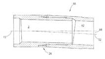
- FIG. 1is a planar view of the first housing of the preferred embodiment.
- FIG. 2Ais a planar view of the collar of the preferred embodiment.
- FIG. 2Bis a top view of the collar seen in FIG. 2A .
- FIG. 2Cis a planar view of the unwrap length of the collar depicted in FIG. 2A .
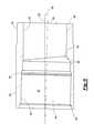
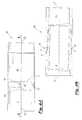
- FIG. 3is a cross-sectional view of the second housing of the preferred embodiment.
- FIG. 4Ais a planar view of the assembled apparatus of the preferred embodiment at a zero degree angle of inclination orientation.
- FIG. 4Bis a cross-section view of the apparatus seen in FIG. 4A .
- FIG. 5Ais a planar view of the assembly apparatus of the preferred embodiment at a one hundred and eighty degree (180) angle of inclination orientation.
- FIG. 5Bis a cross-section view of the apparatus seen in FIG. 5A .
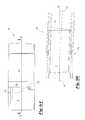
- FIG. 6Ais a planar view of the first housing and collar at a zero (0) degree angle of inclination orientation.
- FIG. 6Bis a planar view of the first housing and collar at a one hundred and eighty (180) degree angle of inclination orientation.
- FIG. 7is a schematic view of the mud motor of the present invention in a straight orientation within a wellbore.
- FIG. 8is a schematic view of the mud motor of FIG. 7 in a bent orientation within a wellbore.
- the first housing 2has a first outer cylindrical surface 4 that extends to surface 6 , and wherein the surface 6 has a generally helical profile 8 .
- the first outer cylindrical surface 4will have an inner portion (not shown in this view), and wherein the dashed line 10 depicts the center axis of the portion formed from cylindrical surface 4 .
- the threaded opening 12Extending from the surface 6 will be the threaded opening seen generally at 12 , sometimes referred to as the pin connection 12 .
- the threaded opening 12includes the outer cylindrical surface 14 that extends to the outer spline members seen generally at 16 which in turn extends to the indentation 18 .
- the splinesare teeth-like projections extending from the pin connection 12 .
- the indentation 18stretches to the external threads 19 , and wherein the threaded opening surface 12 has external threads 19 .
- the external threads 19terminate at the outer cylindrical surface 20 .
- the center axis of the threaded opening 12is represented by the dashed line 22 . As per the teachings of the present invention, the center axis 22 is offset from the center axis 10 , as shown in FIG. 1 by the numeral 99 .
- the collar 26includes an outer cylindrical surface 28 that extends to the first radial end 30 . It should be noted that like numbers appearing in the various figures refer to like components.
- the collar 26has a center of axis 31 .
- the collar 26also contains the collar helical end profile, seen generally at 32 , and wherein the collar helical end profile 32 is reciprocal to and configured to engage the helical profile 8 (helical profile 8 , seen in FIG. 1 ).
- the helical profile 8may also be referred to as a cam surface 8
- the collar helical end profile 32may be referred to as a ramp 32 .
- FIG. 2Bis a top view of the collar 26 seen in FIG. 2A .
- the collar helical end profile 32is shown, along with the outer cylindrical surface 28 .
- the collar 26contains the inner diameter surface 34 , and wherein the inner diameter surface 34 contains the splines 36 (sometimes referred to as the female set of splines 36 ).
- the splines 36will engage with the splines 16 in order to lock the collar 26 in position relative to the first housing 2 as will be more fully explained later in the description.
- FIG. 2Cis a planar view of the entire length (i.e. unwrapped view) of the collar 26 seen in FIG. 2A , and wherein the collar helical end profile 32 is illustrated.
- the profile 32has a sloping surface 38 that extends to the upward facing shoulder 40 , wherein the upward facing shoulder 40 extends to the sloping surface 38 .
- the profile 32is configured to engage with the helical profile 8 of the first housing 2 .
- the first radial end 30is also shown.
- the second housing 42is generally cylindrical in shape.
- the second housing 42has a first outer surface 44 that extends to the second, smaller outer diameter surface 46 which terminates at the radial end 48 .
- Extending radially inwardis the inner diameter portion 50 .
- the inner diameter portion 50has a center of axis denoted by the dashed line 52 , which is also the center of axis for the cylindrical outer surfaces 44 , 46 .
- FIG. 3also illustrates the threaded opening, seen generally at 54 (sometimes referred to as the box connection 54 ), and wherein the threaded opening 54 is configured to engage the threaded opening 12 .
- the threaded opening 54is tilted (i.e. inclined) relative to the outer surfaces 44 , 46 .
- the threaded opening 54contains internal threads 55 .
- the threaded opening 54has a center of axis denoted by the dashed line 56 (sometimes referred to as the titled box angle), and wherein the center of axis 56 is offset from the center of axis 52 by the angle denoted 58 , which in the most preferred embodiment is between 1.5 and 2.0 degrees.
- the box connection 54extends to the indentation 60 which in turn extends to the inner surface 62 .
- the inner surface 62then extends to the eccentric inner surface 64 , and wherein the eccentric inner surface 64 allows for the junction of the inner diameter portion 50 and the inner surface 62 .
- the second housing 42contains the radial end 66 .
- FIG. 4Ais a planar view of the assembled apparatus 68 (sometimes referred to as the adjustable bent sub 68 ) of the preferred embodiment at a zero degree angle of inclination orientation.
- the shoulder 40 of the collar 26abuts the shoulder 69 of the first housing 2 .
- the radial end 30 of the collar 26abuts the radial end 66 of the second housing 42 .
- the center of axis 10 of the housing 2 and the center of axis 52 of the housing 42are aligned, and therefore, at zero orientation.
- FIG. 4Bis a cross-section view of the assembled apparatus 68 taken along line I-I from FIG. 4A .
- FIG. 4Bdepicts the engagement of the collar helical end profile 32 with the helical profile 8 as well as the radial end 30 abutting the radial end 66 .
- the first housing 2is threadedly connected to the second housing 42 .
- the axis of the assembled apparatus 68would be aligned with the drill bit axis.
- FIG. 5Ais a planar view of the assembled apparatus 68 of the preferred embodiment at a 180 degree angle of inclination orientation.
- the first housing 2 and the second housing 42have been separated, and the collar 26 has been repositioned by removing from the spline means, rotationally repositioning the spline means, and then threadedly connecting the first housing 2 and the second housing 42 .
- the shoulder 40 of collar 26has been rotationally separated from the shoulder 69 of first housing 2 , as seen in FIG. 5A .
- FIG. 5Bis a cross-section view of the assembled apparatus 68 taken along line II-II of FIG. 5A .
- FIG. 5Bdepicts the center axis 10 of the first housing 2 as well as the center of axis 52 of the second housing 42 .
- the numeral 98depicts the angle of inclination which is 2 to 4 degrees.
- the numeral angle 98would be the sum of the tilted box angle 58 and the first housing angle 99 (angle between item 10 and item 22 seen in FIG. 1 ) with 180 degree angle of inclination rotation.
- the center of axis 52would be offset from the drill bit axis.
- the assembled apparatus 68represents an adjustable bent sub of a downhole motor assembly in the tilted mode due to the 2 to 4 degree angle of inclination, or more preferably a 3 to 4 degree angle of inclination.
- FIG. 6Aa planar view of the first housing 2 and the collar 26 at zero (0) degree angle of inclination orientation will now be described.
- This viewis the view of FIGS. 4A and 4B , except the second housing 42 has been removed.
- the line 70represents the level of the radial end 30
- line 85represents the level of helical collar end 32 adjacent shoulder 40 .
- FIG. 6Bwhich is planar view of the first housing 2 and collar 26 at a one hundred and eighty (180) degree angle of inclination orientation, the collar 26 has been rotationally displaced by lifting the collar 26 from the splines and repositioning the collar 26 onto the splines (i.e. the collar 26 has been rotated relative to the first housing 2 ).
- the collar 26was disengaged from the spline means, rotated, and the spline means were then re-engaged to the position seen in FIG. 6B .
- the line 72represents the level of the radial end 30 relative to the previous level 70 after this rotational displacement.
- the line 86represents the level of the helical collar end 32 adjacent shoulder 40 .
- the delta Hrepresents the amount of lateral movement of radial end 30 after the rotational displacement and the delta H 2 represents the amount of lateral movement of helical shoulder end 32 adjacent shoulder 40 after the rotational displacement.
- FIG. 7is a schematic view of a mud motor assembly, seen generally at 72 , within a wellbore 74 .
- the mud motor 72contains the power section 76 , the adjustable bent housing apparatus 68 and the bearing section 78 .
- the bearing sectioncontains a drive shaft (DS) that will be connected to the drill bit 80 for drilling the wellbore 74 .
- the power section 76contains an output shaft (OS) that is connected to the drive shaft (DS).
- the power sectiongenerates a rotational movement to the output shaft (OS), which in turn is transferred to the drive shaft.
- the drill bit 80will be turned by the drive shaft in order to drill the wellbore 74 .
- the downhole mud motor assembly 72is connected to a work string 82 .
- FIG. 8is a schematic view of the mud motor of FIG. 7 in a bent orientation within the wellbore 74 . More specifically, the center of axis 10 of the first housing 2 is offset by an angle of three (3) degrees relative to the center of axis 84 of the lower housing 42 . As seen in FIG. 8 , the drill bit 80 will drill in a deviated direction due to the adjustable bent sub's orientation.
Landscapes
- Life Sciences & Earth Sciences (AREA)
- Engineering & Computer Science (AREA)
- Geology (AREA)
- Mining & Mineral Resources (AREA)
- Physics & Mathematics (AREA)
- Environmental & Geological Engineering (AREA)
- Fluid Mechanics (AREA)
- General Life Sciences & Earth Sciences (AREA)
- Geochemistry & Mineralogy (AREA)
- Processing Of Stones Or Stones Resemblance Materials (AREA)
- Earth Drilling (AREA)
Abstract
Description
Claims (24)
Priority Applications (3)
| Application Number | Priority Date | Filing Date | Title |
|---|---|---|---|
| US12/004,346US7882904B2 (en) | 2007-12-20 | 2007-12-20 | Adjustable bent housing apparatus and method |
| CA2708853ACA2708853C (en) | 2007-12-20 | 2008-12-09 | Adjustable bent housing apparatus and method |
| PCT/US2008/086079WO2009094074A1 (en) | 2007-12-20 | 2008-12-09 | Adjustable bent housing apparatus and method |
Applications Claiming Priority (1)
| Application Number | Priority Date | Filing Date | Title |
|---|---|---|---|
| US12/004,346US7882904B2 (en) | 2007-12-20 | 2007-12-20 | Adjustable bent housing apparatus and method |
Publications (2)
| Publication Number | Publication Date |
|---|---|
| US20090159339A1 US20090159339A1 (en) | 2009-06-25 |
| US7882904B2true US7882904B2 (en) | 2011-02-08 |
Family
ID=40787256
Family Applications (1)
| Application Number | Title | Priority Date | Filing Date |
|---|---|---|---|
| US12/004,346Active2028-06-30US7882904B2 (en) | 2007-12-20 | 2007-12-20 | Adjustable bent housing apparatus and method |
Country Status (3)
| Country | Link |
|---|---|
| US (1) | US7882904B2 (en) |
| CA (1) | CA2708853C (en) |
| WO (1) | WO2009094074A1 (en) |
Cited By (16)
| Publication number | Priority date | Publication date | Assignee | Title |
|---|---|---|---|---|
| US20140262530A1 (en)* | 2013-03-12 | 2014-09-18 | Mostar Directional Technologies Inc. | Adjustable Mud Motor Housing Assembly |
| US9605482B2 (en) | 2015-03-05 | 2017-03-28 | Halliburton Energy Services, Inc. | Directional drilling with adjustable bent housings |
| US9702195B2 (en) | 2015-03-05 | 2017-07-11 | Halliburton Energy Services, Inc. | Adjustable bent housings with sacrificial support members |
| US9714549B2 (en) | 2015-03-05 | 2017-07-25 | Halliburton Energy Services, Inc. | Energy delivery systems for adjustable bent housings |
| US9816322B2 (en) | 2015-03-05 | 2017-11-14 | Halliburton Energy Services, Inc. | Adjustable bent housings with disintegrable sacrificial support members |
| US9816369B2 (en) | 2013-12-31 | 2017-11-14 | Halliburton Energy Services, Inc. | Bend measurements of adjustable motor assemblies using strain gauges |
| US9834992B2 (en) | 2015-03-05 | 2017-12-05 | Halliburton Energy Services, Inc. | Adjustment mechanisms for adjustable bent housings |
| US9932821B2 (en) | 2014-10-22 | 2018-04-03 | Halliburton Energy Services Inc. | Bend angle sensing assembly and method of use |
| US9988847B2 (en) | 2013-10-16 | 2018-06-05 | Halliburton Energy Services, Inc. | Downhole mud motor with adjustable bend angle |
| US9995133B2 (en) | 2013-12-31 | 2018-06-12 | Halliburton Energy Services, Inc. | Bend measurements of adjustable motor assemblies using magnetometers |
| US10000972B2 (en) | 2013-08-29 | 2018-06-19 | Halliburton Energy Services, Inc. | Downhole adjustable bent motor |
| US10280685B2 (en) | 2014-09-16 | 2019-05-07 | Halliburton Energy Services, Inc. | Hybrid downhole motor with adjustable bend angle |
| US10436013B2 (en) | 2013-12-31 | 2019-10-08 | Halliburton Energy Services, Inc. | Bend measurements of adjustable motor assemblies using inclinometers |
| US20190338595A1 (en)* | 2018-05-04 | 2019-11-07 | Wenzel Downhole Tools Ulc | Fixed bend assembly |
| US10533378B2 (en) | 2013-12-23 | 2020-01-14 | Halliburton Energy Services, Inc. | Surface actuated downhole adjustable mud motor |
| US10563498B2 (en) | 2015-03-05 | 2020-02-18 | Halliburton Energy Services, Inc. | Adjustable bent housings with measurement mechanisms |
Families Citing this family (2)
| Publication number | Priority date | Publication date | Assignee | Title |
|---|---|---|---|---|
| US8919458B2 (en) | 2010-08-11 | 2014-12-30 | Schlumberger Technology Corporation | System and method for drilling a deviated wellbore |
| US9371696B2 (en)* | 2012-12-28 | 2016-06-21 | Baker Hughes Incorporated | Apparatus and method for drilling deviated wellbores that utilizes an internally tilted drive shaft in a drilling assembly |
Citations (17)
| Publication number | Priority date | Publication date | Assignee | Title |
|---|---|---|---|---|
| US4077657A (en) | 1976-03-22 | 1978-03-07 | Smith, International, Inc. | Adjustable bent sub |
| US4522272A (en) | 1983-03-08 | 1985-06-11 | Baker Oil Tools, Inc. | Apparatus for directional drilling of subterranean wells |
| US4745982A (en) | 1986-11-28 | 1988-05-24 | Wenzel Kenneth H | Adjustable bent sub |
| US4811798A (en) | 1986-10-30 | 1989-03-14 | Team Construction And Fabrication, Inc. | Drilling motor deviation tool |
| US4813497A (en) | 1986-10-15 | 1989-03-21 | Wenzel Kenneth H | Adjustable bent sub |
| US4817740A (en) | 1987-08-07 | 1989-04-04 | Baker Hughes Incorporated | Apparatus for directional drilling of subterranean wells |
| US5029654A (en) | 1990-07-16 | 1991-07-09 | Murray Wilson | Bendable drilling sub |
| US5101915A (en) | 1989-11-02 | 1992-04-07 | Baker Hughes Incorporated | Adjustable angle pipe joint |
| US5125463A (en) | 1990-11-16 | 1992-06-30 | Livingstone Raymond S S | Adjustable bent sub |
| US5139094A (en)* | 1991-02-01 | 1992-08-18 | Anadrill, Inc. | Directional drilling methods and apparatus |
| US5248004A (en) | 1989-11-02 | 1993-09-28 | Baker Hughes Incorporated | Adjustable pipe joint |
| US5343966A (en) | 1991-06-19 | 1994-09-06 | Vector Oil Tool Ltd. | Adjustable bent housing |
| US5479995A (en) | 1994-07-05 | 1996-01-02 | Falgout, Sr.; Thomas E. | Adjustable orienting sub |
| US5495901A (en) | 1995-02-28 | 1996-03-05 | Canadian Downhole Drill Systems Inc. | Surface adjustable adjustable bent housing |
| US6543554B2 (en) | 2001-05-21 | 2003-04-08 | Continental Directional Corp. | Adjustable housing for a mud motor |
| US6554083B1 (en) | 2001-12-05 | 2003-04-29 | Scott Kerstetter | Adjustable bent housing sub for a mud motor |
| US6799646B1 (en) | 2002-09-03 | 2004-10-05 | Tomahawk Downhole, Llc | Adjustable deflecting sub |
- 2007
- 2007-12-20USUS12/004,346patent/US7882904B2/enactiveActive
- 2008
- 2008-12-09WOPCT/US2008/086079patent/WO2009094074A1/enactiveApplication Filing
- 2008-12-09CACA2708853Apatent/CA2708853C/enactiveActive
Patent Citations (17)
| Publication number | Priority date | Publication date | Assignee | Title |
|---|---|---|---|---|
| US4077657A (en) | 1976-03-22 | 1978-03-07 | Smith, International, Inc. | Adjustable bent sub |
| US4522272A (en) | 1983-03-08 | 1985-06-11 | Baker Oil Tools, Inc. | Apparatus for directional drilling of subterranean wells |
| US4813497A (en) | 1986-10-15 | 1989-03-21 | Wenzel Kenneth H | Adjustable bent sub |
| US4811798A (en) | 1986-10-30 | 1989-03-14 | Team Construction And Fabrication, Inc. | Drilling motor deviation tool |
| US4745982A (en) | 1986-11-28 | 1988-05-24 | Wenzel Kenneth H | Adjustable bent sub |
| US4817740A (en) | 1987-08-07 | 1989-04-04 | Baker Hughes Incorporated | Apparatus for directional drilling of subterranean wells |
| US5248004A (en) | 1989-11-02 | 1993-09-28 | Baker Hughes Incorporated | Adjustable pipe joint |
| US5101915A (en) | 1989-11-02 | 1992-04-07 | Baker Hughes Incorporated | Adjustable angle pipe joint |
| US5029654A (en) | 1990-07-16 | 1991-07-09 | Murray Wilson | Bendable drilling sub |
| US5125463A (en) | 1990-11-16 | 1992-06-30 | Livingstone Raymond S S | Adjustable bent sub |
| US5139094A (en)* | 1991-02-01 | 1992-08-18 | Anadrill, Inc. | Directional drilling methods and apparatus |
| US5343966A (en) | 1991-06-19 | 1994-09-06 | Vector Oil Tool Ltd. | Adjustable bent housing |
| US5479995A (en) | 1994-07-05 | 1996-01-02 | Falgout, Sr.; Thomas E. | Adjustable orienting sub |
| US5495901A (en) | 1995-02-28 | 1996-03-05 | Canadian Downhole Drill Systems Inc. | Surface adjustable adjustable bent housing |
| US6543554B2 (en) | 2001-05-21 | 2003-04-08 | Continental Directional Corp. | Adjustable housing for a mud motor |
| US6554083B1 (en) | 2001-12-05 | 2003-04-29 | Scott Kerstetter | Adjustable bent housing sub for a mud motor |
| US6799646B1 (en) | 2002-09-03 | 2004-10-05 | Tomahawk Downhole, Llc | Adjustable deflecting sub |
Cited By (17)
| Publication number | Priority date | Publication date | Assignee | Title |
|---|---|---|---|---|
| US9309721B2 (en)* | 2013-03-12 | 2016-04-12 | Mostar Directional Technologies Inc. | Adjustable mud motor housing assembly |
| US20140262530A1 (en)* | 2013-03-12 | 2014-09-18 | Mostar Directional Technologies Inc. | Adjustable Mud Motor Housing Assembly |
| US10000972B2 (en) | 2013-08-29 | 2018-06-19 | Halliburton Energy Services, Inc. | Downhole adjustable bent motor |
| US9988847B2 (en) | 2013-10-16 | 2018-06-05 | Halliburton Energy Services, Inc. | Downhole mud motor with adjustable bend angle |
| US10533378B2 (en) | 2013-12-23 | 2020-01-14 | Halliburton Energy Services, Inc. | Surface actuated downhole adjustable mud motor |
| US10436013B2 (en) | 2013-12-31 | 2019-10-08 | Halliburton Energy Services, Inc. | Bend measurements of adjustable motor assemblies using inclinometers |
| US9816369B2 (en) | 2013-12-31 | 2017-11-14 | Halliburton Energy Services, Inc. | Bend measurements of adjustable motor assemblies using strain gauges |
| US9995133B2 (en) | 2013-12-31 | 2018-06-12 | Halliburton Energy Services, Inc. | Bend measurements of adjustable motor assemblies using magnetometers |
| US10280685B2 (en) | 2014-09-16 | 2019-05-07 | Halliburton Energy Services, Inc. | Hybrid downhole motor with adjustable bend angle |
| US9932821B2 (en) | 2014-10-22 | 2018-04-03 | Halliburton Energy Services Inc. | Bend angle sensing assembly and method of use |
| US9834992B2 (en) | 2015-03-05 | 2017-12-05 | Halliburton Energy Services, Inc. | Adjustment mechanisms for adjustable bent housings |
| US9816322B2 (en) | 2015-03-05 | 2017-11-14 | Halliburton Energy Services, Inc. | Adjustable bent housings with disintegrable sacrificial support members |
| US9714549B2 (en) | 2015-03-05 | 2017-07-25 | Halliburton Energy Services, Inc. | Energy delivery systems for adjustable bent housings |
| US9702195B2 (en) | 2015-03-05 | 2017-07-11 | Halliburton Energy Services, Inc. | Adjustable bent housings with sacrificial support members |
| US9605482B2 (en) | 2015-03-05 | 2017-03-28 | Halliburton Energy Services, Inc. | Directional drilling with adjustable bent housings |
| US10563498B2 (en) | 2015-03-05 | 2020-02-18 | Halliburton Energy Services, Inc. | Adjustable bent housings with measurement mechanisms |
| US20190338595A1 (en)* | 2018-05-04 | 2019-11-07 | Wenzel Downhole Tools Ulc | Fixed bend assembly |
Also Published As
| Publication number | Publication date |
|---|---|
| US20090159339A1 (en) | 2009-06-25 |
| CA2708853C (en) | 2014-04-29 |
| CA2708853A1 (en) | 2009-07-30 |
| WO2009094074A1 (en) | 2009-07-30 |
Similar Documents
| Publication | Publication Date | Title |
|---|---|---|
| US7882904B2 (en) | Adjustable bent housing apparatus and method | |
| US5117927A (en) | Downhole adjustable bent assemblies | |
| EP0857247B1 (en) | Assembly and process for drilling and completing multiple wells | |
| EP1038087B1 (en) | Assembly and process for drilling and completing multiple wells | |
| US9500031B2 (en) | Rotary steerable drilling apparatus | |
| US9062496B2 (en) | Systems and methods for rotationally orienting a whipstock assembly | |
| US20030173089A1 (en) | Full bore selective location and orientation system and method of locating and orientating a downhole tool | |
| US7681637B2 (en) | Self-orienting guide shoe | |
| US20130160993A1 (en) | Wedge ring for attaching centralizers | |
| AU2013377914A1 (en) | Systems and methods for rotationally orienting a whipstock assembly | |
| US5101906A (en) | Horizontal drilling or completion method | |
| US4641717A (en) | Connector housing | |
| RU2759618C1 (en) | Alignment of the two parts of the tubular assembly | |
| US11078726B2 (en) | Adjustable split thrust ring | |
| US11085241B2 (en) | Adjustable split thrust ring | |
| US8281868B2 (en) | Torque transmitting load shoulder | |
| EA035445B1 (en) | SYSTEM AND METHOD FOR REVISING THE BOREHOLE ALKALINE SUBSYSTEM BY THE CIRCLE | |
| EA038754B1 (en) | Apparatus, system and method for circumferentially orienting a downhole latch subsystem | |
| EA039909B1 (en) | System for circumferentially aligning a downhole latch subsystem in a downhole |
Legal Events
| Date | Code | Title | Description |
|---|---|---|---|
| AS | Assignment | Owner name:ASHMIN, LC,TEXAS Free format text:ASSIGNMENT OF ASSIGNORS INTEREST;ASSIGNORS:VON GYNZ-REKOWSKI, GUNTHER HH;HERBEN, WILLIAM CHRISTIAN;BOLEJACK, DARYL ELLIOT;REEL/FRAME:020333/0397 Effective date:20071217 Owner name:ASHMIN, LC, TEXAS Free format text:ASSIGNMENT OF ASSIGNORS INTEREST;ASSIGNORS:VON GYNZ-REKOWSKI, GUNTHER HH;HERBEN, WILLIAM CHRISTIAN;BOLEJACK, DARYL ELLIOT;REEL/FRAME:020333/0397 Effective date:20071217 | |
| STCF | Information on status: patent grant | Free format text:PATENTED CASE | |
| FPAY | Fee payment | Year of fee payment:4 | |
| AS | Assignment | Owner name:ASHMIN HOLDING LLC, TEXAS Free format text:NUNC PRO TUNC ASSIGNMENT;ASSIGNOR:ASHMIN LC;REEL/FRAME:040219/0539 Effective date:20161103 | |
| MAFP | Maintenance fee payment | Free format text:PAYMENT OF MAINTENANCE FEE, 8TH YR, SMALL ENTITY (ORIGINAL EVENT CODE: M2552) Year of fee payment:8 | |
| AS | Assignment | Owner name:RIVAL DOWNHOLE TOOLS LC, TEXAS Free format text:ASSIGNMENT OF ASSIGNORS INTEREST;ASSIGNOR:ASHMIN HOLDING LLC;REEL/FRAME:049094/0110 Effective date:20190426 | |
| MAFP | Maintenance fee payment | Free format text:PAYMENT OF MAINTENANCE FEE, 12TH YR, SMALL ENTITY (ORIGINAL EVENT CODE: M2553); ENTITY STATUS OF PATENT OWNER: SMALL ENTITY Year of fee payment:12 | |
| AS | Assignment | Owner name:PACIFIC WESTERN BANK D/B/A PACIFIC WESTERN BUSINESS FINANCE, ARIZONA Free format text:SECURITY INTEREST;ASSIGNOR:RIVAL DOWNHOLE TOOLS LLC;REEL/FRAME:061586/0149 Effective date:20221013 | |
| AS | Assignment | Owner name:RIVAL DOWNHOLE TOOLS LLC, TEXAS Free format text:RELEASE BY SECURED PARTY;ASSIGNOR:BANC OF CALIFORNIA F/K/A PACIFIC WESTERN BANK D/B/A PACIFIC WESTERN BUSINESS FINANCE;REEL/FRAME:070484/0567 Effective date:20250312 |