US7881785B2 - Method and apparatus for defrosting a defibrillation electrode - Google Patents
Method and apparatus for defrosting a defibrillation electrodeDownload PDFInfo
- Publication number
- US7881785B2 US7881785B2US12/055,817US5581708AUS7881785B2US 7881785 B2US7881785 B2US 7881785B2US 5581708 AUS5581708 AUS 5581708AUS 7881785 B2US7881785 B2US 7881785B2
- Authority
- US
- United States
- Prior art keywords
- defibrillator
- electrode
- electrodes
- controller
- conductive interface
- Prior art date
- Legal status (The legal status is an assumption and is not a legal conclusion. Google has not performed a legal analysis and makes no representation as to the accuracy of the status listed.)
- Expired - Fee Related, expires
Links
- FRIKNAFRNLOJCX-SDNWHVSQSA-NCCCC(C)(CCC(C)C1C(C)C)C1/C(/C)=C/OChemical compoundCCCC(C)(CCC(C)C1C(C)C)C1/C(/C)=C/OFRIKNAFRNLOJCX-SDNWHVSQSA-N0.000description1
Images


Classifications
- A—HUMAN NECESSITIES
- A61—MEDICAL OR VETERINARY SCIENCE; HYGIENE
- A61N—ELECTROTHERAPY; MAGNETOTHERAPY; RADIATION THERAPY; ULTRASOUND THERAPY
- A61N1/00—Electrotherapy; Circuits therefor
- A61N1/02—Details
- A61N1/04—Electrodes
- A61N1/0404—Electrodes for external use
- A61N1/0408—Use-related aspects
- A61N1/046—Specially adapted for shock therapy, e.g. defibrillation
- A—HUMAN NECESSITIES
- A61—MEDICAL OR VETERINARY SCIENCE; HYGIENE
- A61N—ELECTROTHERAPY; MAGNETOTHERAPY; RADIATION THERAPY; ULTRASOUND THERAPY
- A61N1/00—Electrotherapy; Circuits therefor
- A61N1/18—Applying electric currents by contact electrodes
- A61N1/32—Applying electric currents by contact electrodes alternating or intermittent currents
- A61N1/38—Applying electric currents by contact electrodes alternating or intermittent currents for producing shock effects
- A61N1/39—Heart defibrillators
- A61N1/3904—External heart defibrillators [EHD]
Definitions
- the present inventionrelates to methods and devices for resuscitating a patient. More particularly, the present invention relates to electric defibrillators and thawing frozen defibrillation electrodes used with electric defibrillators.
- Patient conditions that may require resuscitationinclude, but are not limited to, cardiac arrest, bradycardia, tachycardia, ventricular fibrillation and respiratory arrest.
- One example of a technique for resuscitating a patientis to use an electric defibrillator to apply electrical energy to the patient.
- An electric defibrillatortypically includes a power source and at least two defibrillation electrodes that provide a connection with the skin of a patient for electricity to be administered to the patient.
- defibrillation electrodesare disposed upon the chest region of a patient such that electrical energy can be administered to the patient.
- AEDsautomated external defibrillators
- Cardiac Science's Powerheart®Medtronic's LIFEPAK®
- Defibtech's LifelineTMPhillips' HeartStartTM
- Zoll's AED Plus®Zoll's AED Plus®
- AEDsare continuously operational and ready for use on a moment's notice. Any delay in the ability of a rescuer to use such a device in an emergency can mean the difference between life and death for a patient. One such delay may occur as a result of the defibrillation electrodes being frozen. Because AEDs are highly portable, they are often stored in automobiles or other unheated places. In cold weather, portions of the defibrillation electrodes may freeze. In order for a defibrillation electrode to properly deliver an appropriate electrical impulse as described, the electrode must not be frozen. In current practice, if an electrode is frozen, a rescuer must either replace the electrode with an unfrozen one, or use external means such as a heater to thaw the electrode. Often, in critical situations, a frozen electrode results in valuable time wasted and in the worst case may result in death to a patient.
- an automated external defibrillator with defrosting capabilitiesincludes a portable housing containing a battery powered energy source and a controller.
- the embodimentalso includes at least a pair of electrodes operably coupled to the housing.
- the electrodesare releasably attachable to an external portion of a patient in need of resuscitation.
- each of the electrodesincludes a conductive interface medium having physical properties dependent upon a desired temperature range of about 32° F. to 122° F.
- the controlleris configured to selectively heat the conductive interface medium by applying a limited amount of electrical impulse from the energy source to raise the temperature of the conductive interface medium toward the desired range.
- an automated external defibrillator with defrosting capabilitiesincludes a pair of preconnected electrodes including an outer hydrogel layer on each electrode having physical properties dependent upon a normal temperature range of about 32° F. to 122° F. Also included is a housing having a battery powered energy source and a controller that selectively heats the hydrogel layer by applying a limited amount of electrical impulse to raise the temperature of the hydrogel layer to the normal range.
- a method of controlling the operating conditions of defibrillation electrodes of an automated external defibrillatorincludes providing a pair of electrodes releasably attachable with an external portion of a patient in need of resuscitation where each electrode has a conductive interface medium having physical properties dependent upon a desired temperature range of about 32° F. to 122° F. The method also including automatically causing the automated external defibrillator to deliver a limited electrical impulse to the defibrillation electrodes so as to heat the defibrillation electrodes to the desired temperature range.
- FIG. 1illustrates generally an example of an electric defibrillator.
- FIG. 2 aillustrates generally an example of a defibrillator electrode.
- FIG. 2 billustrates generally an alternate example of a defibrillator electrode.
- FIG. 3 aillustrates generally an example of pre-connected electrodes.
- FIG. 3 billustrates generally an example of pre-connected electrodes.
- FIG. 3 cillustrates generally an example of pre-connected electrodes.
- FIG. 3 dillustrates generally an example of pre-connected electrodes.
- FIG. 3 eillustrates generally an example of pre-connected electrodes.
- FIG. 4illustrates generally a rescuer using an electric defibrillator on a patient.
- FIG. 5illustrates generally an electric defibrillator according to the subject matter disclosed herein.
- FIG. 6 a and FIG. 6 billustrate generally an electric defibrillator according to the subject matter disclosed herein.
- FIG. 7illustrates generally an electric defibrillator according to the subject matter disclosed herein.
- FIG. 8illustrates generally an electric defibrillator according to the subject matter disclosed herein.
- FIG. 9illustrates generally a flow chart example of a method of defrosting an electrode according to the subject matter disclosed herein.
- FIG. 10illustrates generally a flow chart example of a method of defrosting an electrode according to the subject matter disclosed herein.
- FIG. 11illustrates generally a flow chart example of a method of assisting a rescuer to defrost an electrode according to the subject matter disclosed herein.
- FIG. 12illustrates generally an electric defibrillator according to the subject matter disclosed herein.
- FIG. 13illustrates generally a flow chart example of a method of assisting a rescuer to defrost an electrode according to the subject matter disclosed herein.
- FIG. 14illustrates generally a flow chart example of a method of assisting a rescuer to defrost an electrode according to the subject matter disclosed herein.
- FIG. 15illustrates generally a flow chart example of a method of controlling the operating conditions of a defibrillation electrode according to the subject matter disclosed herein.
- FIG. 1illustrates generally an example of an electric defibrillator 101 .
- electric defibrillator 101includes one or more power sources 102 .
- power source 102includes one or more batteries.
- power source 102also includes one or more capacitors.
- power source 102is adapted to provide energy sufficient to provide an electrical impulse capable of stimulating a heart.
- defibrillator 101includes controller 103 .
- Controller 103is adapted to initiate, adjust, and/or monitor functions of defibrillator 101 .
- controller 103is adapted to initiate or adjust delivery of an electric impulse for purposes of providing electrical therapy to a patient.
- defibrillator 101further includes user interface 107 .
- User interface 107is adapted to allow communication between a user and controller 103 .
- user interface 107is adapted to allow a user to program controller 103 .
- defibrillator 101also includes at least one electrode 105 .
- electrode 105is connected to electrical conductor 106 such that electrode 105 is in electrical connection with power source 102 .
- electrode 105is adapted to be placed in contact with a patient and serve as a connection for delivery of electrical energy to a patient.
- at least two electrodes 105are required so that an electrical connection is provided across the body of a patient such that a current may be driven through the body of a patient to stimulate the patient's heart.
- defibrillator 101further includes at least one sensor 108 .
- Sensor 108may be adapted to determine conditions of components of defibrillator 101 .
- sensor 108is adapted to determine a temperature of electrode 105 .
- sensor 108is adapted to determine the amount of energy stored in power source 102 .
- sensor 108is adapted to determine conditions of components of defibrillator 101 .
- sensor 108is adapted to determine whether electrode 105 is frozen.
- sensor 108is adapted to determine conditions external to defibrillator 101 .
- sensor 108may also be capable of detecting defibrillator movement or other events commonly occurring prior to defibrillation, such as movement of a defibrillator panel.
- electrode 105is a defibrillation electrode adapted to apply an electric impulse to a patient. If electrode 105 is frozen, or very cold, it will likely not function properly to apply an electrical impulse to a patient. Therefore, a frozen electrode 105 must be defrosted quickly and efficiently so that electrode 105 will function effectively to apply an electrical impulse to a patient. More specifically, certain components of the electrode such as a hydrogel layer or other conductive interface medium can readily freeze when temperatures drop below a desired temperature range. The physical properties of the conductive interface medium often requires a desired, normal temperature range for operation to generally be about 32° F. to 122° F. Such a range is needed for safe and reliable defibrillation operation. Consequently, the controller of the present invention is designed to selectively heat the conductive interface medium by applying a limited amount of electrical impulse from the energy source to raise the temperature of the conductive interface medium to the desired range.
- using the controller to selectively signal the electrical impulses or other means to warm and defrost the electrodescan be done in a variety of ways.
- a sensor 108 in the defibrillatormay detect a freezing temperature in the proximity of the electrodes.
- a sensor that detects when the defibrillator is moved or openedcan signal defrosting, as such actions will often occur just prior to defibrillation.
- Sending sensor data to the controller in this waywill also ensure the defibrillator is ready for use at desired times. Additional signaling events may follow routine or automatic self testing operations by the defibrillator.
- the controllermay be programmed with various safety features to recognize and prevent continuous or repetitive signaling data that might result in significant battery usage and drain. Such features ensure that the defibrillator will be sufficiently charged for proper use.
- FIG. 2 aillustrates generally one example of a defibrillation electrode 201 .
- Defibrillation electrode 201includes a lead location 202 and a patient contact surface 203 .
- patient surface 203is adapted to be placed in contact with a patient in order to deliver electrical therapy to the patient.
- Lead location 202is adapted to connect an electrode 201 to an electrical conductor 106 .
- lead location 202includes a lead 204 which may be made of a conductive material.
- Electrode 201further includes base layer 205 .
- base layer 205is any non-conductive material. According to the embodiment illustrated in FIG.
- Electrode 201further includes conductive layer 206 .
- layer 206may be made of foil or other conductive material.
- conductive layer 206is disposed in contact with lead 204 to provide electrical connectivity between lead 204 and conductive layer 206 .
- Electrode 201further includes patient contact portion 207 .
- Conductive layer 206is adapted to transfer voltage or current from lead 204 to patient contact portion 207 .
- patient contact portion 207may be entirely comprised of a hydrogel layer or conductive interface medium 208 disposed in electrical contact with conductive layer 206 .
- the conductive interface medium 208is generally comprised of a conductive gel or similar material.
- the conductive interface medium 208may be comprised of a tape or an adhesive of various kinds. For example, use of a nanopillar tape comprised of sheets of elastic, sticky polymers of a multiplicity of nanopillars or related medical tapes might be used in some designs.
- hydrogel layer 208is adapted to reduce variations in conductance when patient contact surface 203 is placed in contact with a patient and electrical energy is applied to electrode 201 .
- the hydrogel 208may have both conductive properties for transmitting energy and adhesive properties for attaching to a patient's skin. Specifically, the hydrogel helps make the electrodes releasably attachable to an external portion of a patient in need of resuscitation.
- Patient contact portion 207may alternatively be comprised of a number of layers as set forth in FIG. 2 b .
- One layerbeing a hydrogel layer 208 disposed in electric contact with conductive layer 206 .
- Patient contact portion 207may further include a foil layer 209 in contact with hydrogel layer 208 .
- foil layer 209is a thin layer of conductive material adapted to transfer energy through hydrogel layer 208 to the patient contact surface 203 .
- Patient contact portion 207may further include an adhesive layer 210 .
- Adhesive layer 210is adapted to secure patient contact surface 203 to the skin of a patient.
- adhesive layer 210is made of any material with adhesive properties that further allows conduction of electricity to the skin of a patient.
- the term “frozen” as used hereinincludes any temperature driven malfunction of defibrillation electrode 201 .
- electrode 201does not function correctly because patient contact portion 207 is frozen, and therefore cannot ensure desired delivery of electrical energy to patient contact portion 207 .
- electrode 201is enclosed in a package 211 prior to use.
- Package 211is adapted to protect the electrode prior to use to revive a patient.
- a single electrode 201is enclosed in package 211 .
- two or more electrodes 201are enclosed in package 211 .
- package 211is made of a material capable of protecting electrode 201 prior to use.
- package 211is a thin, flexible material.
- package 211is a tensile material.
- package 211may include additional features such as additional electrical connections.
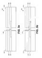
- FIG. 3 a and FIG. 3 billustrate generally examples of pre-connected electrodes 301 and 311 respectively, in a horizontal pre-connection arrangement. Electrodes 301 and 311 are typically pre-connected so that one or more conditions of electrodes 301 and 311 can be determined by applying a current through the electrodes. According to the example of FIG. 3 a , electrodes 302 and 303 are pre-connected by breakable electrode connector 304 .
- breakable electrode connector 304is a conductive material such as a metal that is adapted to provide an electrical connection to allow current to flow between electrodes 302 and 303 . In various embodiments, breakable electrode connector 304 is adapted to establish an electrical connection between hydrogel layers 305 or foil 306 of electrodes 302 and 303 .
- Electrodes 302 and 303are connected for test purposes prior to the use of electrodes 302 and 303 to revive a patient. To use electrodes 302 and 303 to revive a patient, breakable electrode connector 304 is broken, and an electrical connection no longer exists between electrodes 302 and 303 .
- FIG. 3 aonly shows breakable electrical connector 304 connecting hydro-gel layers, it is to be understood that electrical connector 304 can be adapted to connect any or all layers of electrodes 302 and 303 .
- electrodes 312 and 313are pre-connected in a horizontal orientation by perforated electrode connector 314 .
- perforated electrode connector 314is an extension of hydrogel layer 315 that is perforated such that a rescuer can easily separate electrode 312 from electrode 313 .
- perforated electrode connector 314is adapted to establish an electrical connection between hydrogel layers 315 of electrodes 312 and 313 . Electrodes 312 and 313 are connected for test purposes prior to the use of electrodes 312 and 313 to revive a patient. To revive a patient, perforated electrode connector 314 is separated, and an electrical connection no longer exists between electrodes 312 and 313 .
- perforated electrical connector 314can be adapted to connect any or all layers of electrodes 312 and 313 .
- foil layers 316 of electrodes 312 and 313could be connected by foil shaped in a serpentine pattern as shown in FIG. 6 b to provide a resistive heating element.
- FIG. 3 cillustrates generally electrodes 322 and 323 pre-connected in a horizontal orientation.
- adhesive layers 324 of electrodes 322 and 323are separated by electrode separator 320 .
- electrode separator 320is made of a non-conductive material, and contacts both adhesive layers 324 .
- Adhesive layers 324typically comprising hydrogel or a similar substance. Holes 321 in electrode separator 320 allow adhesive from adhesive layers 324 to establish an electrical connection between electrode 322 and electrode 323 . To revive a patient, electrode 322 and electrode 323 are removed from electrode separator 320 , and electrical connection no longer exists between electrodes 322 and 323 .
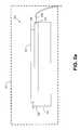
- FIG. 3 dillustrates generally electrodes 332 and 333 pre-connected in a vertical orientation and enclosed in package 340 .
- package 340is a hard, tensile material.
- Package 340includes two opposed interior surfaces 342 and 343 .
- Electrode 332is generally disposed upon interior surface 342 and electrode 333 is disposed upon interior surface 343 .
- an adhesive layer 345is located between interior surface 342 and electrode 332 .
- adhesive layer 346is located between interior surface 343 and electrode 333 .
- the embodiment shown in FIG. 3 dshows electrodes 332 and 333 partially folded back for illustration purposes so that the components underneath the electrodes may be better understood.
- the embodiment illustrated in FIG. 3 dfurther includes external electrical contacts 347 and 348 and interior electrical contacts 349 and 350 .
- Internal electrical contacts 349 and 350are disposed on interior surfaces 342 and 343 such that interior electrical contacts 349 and 350 provide an electrical connection with adhesive surfaces 345 and 346 when adhesive layers 345 and 346 are disposed upon interior surfaces 342 and 343 .
- Interior electrical contacts 349 and 350are in electrical contact with external electrical contacts 347 and 348 .
- External electrical contactsare adapted to accept an electrical connection with electrical conductors 351 and 352 such that a closed loop connection is formed with a power source connected to electrical conductors 351 and 352 and a current can be forced through electrodes 332 and 333 .
- electrode 332 and electrode 333are removed from interior surfaces 342 and 343 and placed on a patient's chest so that interior electrical contacts 349 and 350 are no longer in electrical contact with adhesive layers 345 and 346 and electrical connection no longer exists between electrodes 332 and 333 .
- FIG. 3 ediscloses an embodiment where electrodes 332 and 333 are disposed on interior surfaces 342 and 343 .
- Surfaces 342 and 343are comprised of a conductive surface such that current may travel between electrodes 332 and 333 . Therefore, a connection is provided with the power source such that current can be forced through electrodes 332 and 333 via their electrical connection.
- the electrodes 322 and 333are removed from surfaces 342 and 343 when used for defibrillation.
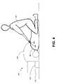
- FIG. 4illustrates generally the use of electric defibrillator 401 to resuscitate patient 402 .
- patient 402is in need of therapy from electric defibrillator 401 .
- Rescuer 403places both electrodes 404 in contact with skin 405 of patient 402 .
- Adhesive layers of electrodesare disposed upon skin such that adhesive layers provide an electrical connection with skin 405 .
- Electrodes 404are electrically connected to the remainder of defibrillator 401 through electrical conductors 408 . According to the example of FIG.
- rescuer 403when rescuer 403 has placed electrodes 404 in contact with patient 402 , rescuer 403 activates electric defibrillator 401 and an electrical impulse is applied from power source 407 through the electrodes 404 to patient 402 .
- Controller 410controls delivery of the electrical impulse.
- FIG. 5illustrates generally one embodiment of electric defibrillator 501 according to the subject matter disclosed herein.
- the example of FIG. 5is identical to the example shown in FIG. 1 , except defibrillation electrodes are pre-connected as shown in FIG. 3 a , FIG. 3 b , FIG. 3 c , FIG. 3 d , or FIG. 3 e .
- the connection between the pre-connected electrodesprovides a current path such that a current can be driven through the electrodes.
- the hydrogel layers 208 of each electrodeare in electrical contact with each other. It is to be understood that any pre-connection current path that is provided between hydrogel layers 208 is within the scope of the subject matter disclosed herein.
- defibrillator 501drives current through electrical conductors 506 and through hydrogel portions 208 of electrodes 505 .
- controller 503initiates, adjusts, and/or monitors the current driven through hydrogel portions 208 of electrodes 505 .
- the currentmay be a DC current, an AC current, an intermittent DC current, or an intermittent AC current.
- currentis driven at a rate and intensity such that hydrogel layers 208 of electrodes 505 absorb the current and thaw electrode 505 without overheating and therefore damaging any component of electrodes 505 .
- Controller 503initiates, adjusts, and/or monitors driving of current into electrodes 505 .
- the embodiments disclosed in FIG. 5allow the ability to automatically thaw electrodes 505 and can be implemented via a programming change of controller 503 .
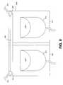
- FIG. 6 a and FIG. 6 billustrate generally one embodiment of defibrillator 607 adapted to thaw electrode 601 according to the subject matter disclosed herein.
- foil 602 of electrode 601is used as a heating element to defrost electrode 601 .
- FIG. 6 aillustrates electrode 601 .
- Electrode 601is similar to electrodes 201 illustrated in FIGS. 2 a and 2 b , however electrode 601 includes two leads 603 and 604 .
- leads 603 and 604are connected to electrical conductors 605 and 606 and provide an electrical connection between foil 602 and the other components located in the base 611 of the defibrillator including the power source.
- defibrillator 607is adapted to direct current through foil 602 . Because foil 602 is made of a conductive element, current directed through foil 602 causes heating of foil 602 and thus dissipates heat to thaw electrode 601 .
- foil 602is not a flat, uniform layer such as the conductive layer 206 or foil 209 illustrated in FIG. 2 .
- FIG. 6 billustrates an alternative embodiment of foil 602 as a serpentine structure. The arrangement of foil 602 as a serpentine structure as opposed to a flat, uniform layer maximizes the ability of foil 602 to dissipate heat.
- foil 602is arranged as a helical structure to maximize the ability of foil 602 to dissipate heat. It is to be understood that any shape, size, or structure of foil 602 is within the scope of the subject matter described herein.
- FIG. 7illustrates generally one embodiment of defibrillator 701 adapted to thaw electrodes 705 and 706 according to the subject matter disclosed herein.
- Pre-connected electrodes 705 and 706are similar to pre-connected electrodes 322 and 323 as illustrated in FIG. 3 c , and further include electrode separator 707 similar to electrode separator 320 .
- the embodiment illustrated in FIG. 7further includes resistive heating element 702 .
- Resistive heating element 702is embedded in electrode separator 707 .
- Resistive heating element 702is adapted to include leads 704 and 703 .
- Leads 703 and 704are further adapted to be connected to the base 711 and power source of the defibrillator via conductors 713 and 715 such that a current may be driven through resistive heating element 702 .
- Resistive heating element 702is adapted to emit heat and thus thaw electrodes 705 and 706 . It is to be understood that resistive heating element 702 may be arranged in any structure to maximize the ability of resistive heating element 702 to dissipate heat to defrost the electrodes 705 and 706 . In one example, resistive heating element 702 may be a serpentine structure as illustrated in FIG. 6 b.
- FIG. 8illustrates generally one embodiment of defibrillator adapted to thaw electrodes 832 and 833 according to the subject matter disclosed herein.
- FIG. 8includes a package 840 having two interior surfaces 842 and 843 . Electrodes 832 and 833 and respective adhesive layers 845 and 846 are located on these interior surfaces and are partially folded back for illustration purposes.
- Package 840is similar to package 340 of FIG. 3 d , however, package 840 includes conductive element 800 .
- Package 840includes external connectors 847 and 848 .
- Conductive element 800provides an electrical connection between external connectors 847 and 848 . According to this embodiment, conductive element 800 functions as a heating element.
- External connectors 847 and 848are adapted to be connected to a power source through electrical connectors 851 and 852 and conductive element 800 such that heat is emitted into package 840 .
- Package 840acts as an insulator trapping emitted heat, and thus frozen electrodes 832 and 833 are thawed. It is to be understood that package 840 is used for illustration purposes only. Any package for electrodes may include conductive element 800 and external connectors 847 and 848 for purposes of thawing a frozen electrode. It is further to be understood that conductive element 800 may be arranged in any structure to maximize the ability of conductive element to dissipate heat into package 840 . In one example, conductive element 800 may be a serpentine structure as illustrated in FIG. 6 b.
- FIG. 9illustrates one embodiment of a method of defrosting an electrode of an electric defibrillator according to the subject matter disclosed herein.
- a rescuerhas access to an electric defibrillator 101 , as shown generally in FIG. 1 .
- Defibrillator 101includes at least one frozen electrode 105 .
- Electrode 105may be frozen because, for example, it has been stored in an automobile in cold weather for a period of time.
- the power of defibrillator 101is activated.
- controller 103receives a signal initiated by rescuer that indicates electrode 105 is frozen.
- one or more pulses of electrical energyare delivered to electrode 105 .
- the delivery of electrical energyis at a level sufficient to defrost the electrode 105 .
- electrical energyis delivered such that damage to components of electrode 105 is minimized.
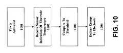
- FIG. 10illustrates one embodiment of a method of defrosting an electrode of an electric defibrillator 101 according to the subject matter disclosed herein.
- a rescuerhas access to an electric defibrillator 101 .
- Defibrillator 101includes at least one frozen electrode 105 .
- Defibrillator 101further includes at least one sensor 108 adapted to measure a temperature of electrode 105 and communicate that temperature to controller 103 .
- the power of defibrillator 101is activated.
- controller 103receives a signal from sensor 108 that indicates a measurement of temperature.
- controller 103is adapted to compare the temperature measurement to one or more thresholds.
- controller 103may be adapted to vary the duration or intensity of an electrical impulse based on the measured temperature of electrode 105 , or any other condition internal or external to defibrillator 101 .
- One or more pulses of electrical energyare delivered to electrode 105 .
- the delivery of electrical energyis at a level sufficient to defrost electrode 105 .
- electrical energyis delivered such that damage to components of electrode 105 is minimized.
- FIG. 11illustrates generally one example of a method of assisting a rescuer to defrost electrode 105 of defibrillator 101 .
- electric defibrillator 101is provided to a rescuer, Electrode 105 of defibrillator 101 is frozen.
- sensors 108 of defibrillator 101may determine that electrode 105 is frozen.
- rescuermay determine that electrode 105 is frozen.
- the rescueris provided instructions to defrost electrode 105 .
- instructionsmay indicate to a rescuer how to initiate the defrosting of electrode 105 .
- instructionsmay indicate that controller 103 has initiated defrosting electrode 105 .
- controller 103may initiate defrosting of electrode 105 automatically.
- an electrical impulseis provided sufficient to defrost electrode 105 as discussed herein with respect to FIGS. 3 a - e , 5 , 6 a - b , 7 , and 8 .
- electrical energyis delivered such that damage to components of electrode 105 is minimized.
- FIG. 12illustrates generally an example of electric defibrillator 1201 according to the subject matter disclosed herein.
- Electric defibrillator 1201includes electrode defroster 1210 .
- electrode defroster 1210is coupled to electric defibrillator 1201 .
- electrode defroster 1210is a component separate to defibrillator 1201 .
- controller 1203is adapted to initiate, adjust, and/or monitor electrode defroster 1210 .
- Defibrillator 1201also includes electrode 1205 .
- electrode 1205is stored in package 1211 .
- electrode defroster 1210is adapted to be positioned proximally to package 1211 to defrost electrode 1205 .
- electrode defroster 1210is adapted to be positioned proximally to electrode 1205 outside of package to defrost electrode 1205 . In one embodiment, electrode defroster 1210 is adapted to contact electrode pouch 1211 to defrost electrode 1205 . In one embodiment, electrode defroster 1210 is adapted to be positioned proximally to electrode 1205 outside of package to defrost electrode 1205 . In various embodiments, electrode defroster 1210 is adapted to contact at least one portion of electrode 1205 . In one embodiment, electrode defroster 1210 is adapted to contact lead 1204 of electrode 1205 . In another embodiment, electrode defroster 1210 is adapted to contact conductive portion 1206 of electrode 1205 . In yet another embodiment, electrode defroster is adapted to contact patient contact portion 1209 of electrode 1205 .
- electrode defroster 1210is adapted to deliver energy to electrode 1205 .
- electrode defroster 1210is adapted to deliver energy in the form of electrical energy to electrode 1205 .
- electrical energyis applied to one or more portions of electrode 1205 such that electrical energy is converted to heat.
- electrical energyis applied to lead 1204 of electrode 1205 .
- electrical energyis applied to conductive layer 1206 of electrode 1205 .
- electrical energyis applied to hydrogel layer 1207 of electrode 1205 .
- electrical energyis applied to foil layer 1208 .
- electrode defrosteris adapted to deliver heat directly to electrode 1205 .
- electrode defrosteris a heat element.
- electrode defrosteris placed proximally to any portion of electrode 1205 to defrost it.
- electrode defroster 1210is powered by defibrillator 1201 .
- electrode defrosteris powered by a power source external to defibrillator 1201 .
- FIG. 13illustrates generally a flow chart example of a method defrosting an electrode according to the subject matter disclosed herein.
- FIG. 13illustrates one embodiment of a method of defrosting an electrode of an electric defibrillator 1201 according to the subject matter disclosed herein.
- a rescuerhas access to an electric defibrillator 1201 .
- Defibrillator 1201includes at least one frozen electrode 1205 .
- Defibrillator 1201further includes at least one electrode defroster 1210 .
- the power of defibrillatoris active.
- a rescuerdetermines that electrode 1205 is frozen.
- rescuerdetermines how to dispose electrode defroster 1210 in relation to electrode 1205 .
- rescuerdisposes electrode defroster 1210 proximally to or in contact with electrode 1205 .
- electrode defroster 1210thaws electrode 1205 .
- FIG. 14illustrates generally a flow chart example of a method of assisting a rescuer to defrost electrode 1205 .
- defibrillator 1205is provided to a rescuer. Electrode 1205 of defibrillator 1201 is frozen.
- electrode defroster 1210is provided to rescuer.
- instructions to use electrode defroster 1210 to defrost electrode 1205are provided to rescuer.
- the rescuerpositions electrode defroster 1210 as directed by instructions provided at 1403 .
- electrode defroster 1210delivers energy to defrost electrode 1205 .
- FIG. 15illustrates a similar embodiment of a method of controlling the operating conditions of defibrillation electrodes of an automated external defibrillator.
- a pair of preconnected electrodesis provided which are adapted to releasably attach to an external portion of a patient.
- the electrodesgenerally attachable to the chest of a patient needing resuscitation.
- Each of the electrodes providedhas a conductive interface medium having physical properties dependent upon a desired temperature range of about 32° F. to 122° F.
- the AEDis automatically caused to deliver a limited electrical impulse to the defibrillation electrodes so as to heat the defibrillation electrodes to the desired temperature range.
- Using a sensor to indicate if the electrode is frozenmay be included in this method. Further, such a process may utilize a resistive heating element or be done during operation of the AED prior to delivery of a defibrillator pulse through the electrodes.
- currentshall be kept low enough to prevent damaging local heating effects.
- the pulse duration and periodicity of the currentshall be compatible with the specific electrode type and characteristics to allow for an even and non-destructive energy absorption by the electrodes to effect an even and successful defrosting.
- a preferred pulse energymay be about 10 to 20 Joules, for example.
- the number of pulsesmay be determined by the initial temperature of the electrodes and the mass of the electrodes.
- the time between pulsesmay be determined by the ability of a specific electrode to absorb thermal energy.
- the voltage usedshall be low enough to avoid internal arcing and to keep the current low enough to prevent excessive local heating. For example, a preferred embodiment could use a voltage range of 50 to 500 Volts.
- Total defrosting energymay be approximately in the 200 J range in some embodiments which may be roughly equivalent to one low energy defibrillation shock.
- resistanceis generally kept low enough not to interfere with the defibrillation function. This might be below 5 Ohms, in some embodiments, for example.
- a variety of safety featuresare possible to avoid danger associated with energy impulses used to defrost electrodes as set forth.
- the electrodesare contained in the packaging, there will be no hazard.
- Some devicesmay utilize features to detect if this packaging is torn.
- Safetycan also be insured via voice and/or visual prompts similar to those used when energy is being delivered to the patient. When defrosting is in progress, the user will be instructed to not handle nor open the electrode pouch. When defrosting is complete, the normal prompting sequence can be resumed.
Landscapes
- Health & Medical Sciences (AREA)
- Radiology & Medical Imaging (AREA)
- Engineering & Computer Science (AREA)
- Biomedical Technology (AREA)
- Nuclear Medicine, Radiotherapy & Molecular Imaging (AREA)
- Cardiology (AREA)
- Life Sciences & Earth Sciences (AREA)
- Animal Behavior & Ethology (AREA)
- General Health & Medical Sciences (AREA)
- Public Health (AREA)
- Veterinary Medicine (AREA)
- Heart & Thoracic Surgery (AREA)
- Electrotherapy Devices (AREA)
Abstract
Description
Claims (19)
Priority Applications (3)
| Application Number | Priority Date | Filing Date | Title |
|---|---|---|---|
| US12/055,817US7881785B2 (en) | 2008-03-26 | 2008-03-26 | Method and apparatus for defrosting a defibrillation electrode |
| EP09156315.5AEP2105162B1 (en) | 2008-03-26 | 2009-03-26 | Method and apparatus for defrosting a defibrillation electrode |
| US12/986,672US8260414B2 (en) | 2008-03-26 | 2011-01-07 | Method and apparatus for defrosting a defibrillation electrode |
Applications Claiming Priority (1)
| Application Number | Priority Date | Filing Date | Title |
|---|---|---|---|
| US12/055,817US7881785B2 (en) | 2008-03-26 | 2008-03-26 | Method and apparatus for defrosting a defibrillation electrode |
Related Child Applications (1)
| Application Number | Title | Priority Date | Filing Date |
|---|---|---|---|
| US12/986,672ContinuationUS8260414B2 (en) | 2008-03-26 | 2011-01-07 | Method and apparatus for defrosting a defibrillation electrode |
Publications (2)
| Publication Number | Publication Date |
|---|---|
| US20090248128A1 US20090248128A1 (en) | 2009-10-01 |
| US7881785B2true US7881785B2 (en) | 2011-02-01 |
Family
ID=40942496
Family Applications (2)
| Application Number | Title | Priority Date | Filing Date |
|---|---|---|---|
| US12/055,817Expired - Fee RelatedUS7881785B2 (en) | 2008-03-26 | 2008-03-26 | Method and apparatus for defrosting a defibrillation electrode |
| US12/986,672Expired - Fee RelatedUS8260414B2 (en) | 2008-03-26 | 2011-01-07 | Method and apparatus for defrosting a defibrillation electrode |
Family Applications After (1)
| Application Number | Title | Priority Date | Filing Date |
|---|---|---|---|
| US12/986,672Expired - Fee RelatedUS8260414B2 (en) | 2008-03-26 | 2011-01-07 | Method and apparatus for defrosting a defibrillation electrode |
Country Status (2)
| Country | Link |
|---|---|
| US (2) | US7881785B2 (en) |
| EP (1) | EP2105162B1 (en) |
Cited By (49)
| Publication number | Priority date | Publication date | Assignee | Title |
|---|---|---|---|---|
| US20110106192A1 (en)* | 2008-03-26 | 2011-05-05 | Nassif Rabih C | Method and apparatus for defrosting a defibrillation electrode |
| US8613708B2 (en) | 2010-10-08 | 2013-12-24 | Cardiac Science Corporation | Ambulatory electrocardiographic monitor with jumpered sensing electrode |
| US8613709B2 (en) | 2010-10-08 | 2013-12-24 | Cardiac Science Corporation | Ambulatory electrocardiographic monitor for providing ease of use in women |
| US8626277B2 (en) | 2010-10-08 | 2014-01-07 | Cardiac Science Corporation | Computer-implemented electrocardiographic data processor with time stamp correlation |
| USD717955S1 (en) | 2013-11-07 | 2014-11-18 | Bardy Diagnostics, Inc. | Electrocardiography monitor |
| US9037477B2 (en) | 2010-10-08 | 2015-05-19 | Cardiac Science Corporation | Computer-implemented system and method for evaluating ambulatory electrocardiographic monitoring of cardiac rhythm disorders |
| USD744659S1 (en) | 2013-11-07 | 2015-12-01 | Bardy Diagnostics, Inc. | Extended wear electrode patch |
| US9345414B1 (en) | 2013-09-25 | 2016-05-24 | Bardy Diagnostics, Inc. | Method for providing dynamic gain over electrocardiographic data with the aid of a digital computer |
| US9364155B2 (en) | 2013-09-25 | 2016-06-14 | Bardy Diagnostics, Inc. | Self-contained personal air flow sensing monitor |
| US9408551B2 (en) | 2013-11-14 | 2016-08-09 | Bardy Diagnostics, Inc. | System and method for facilitating diagnosis of cardiac rhythm disorders with the aid of a digital computer |
| US9408545B2 (en) | 2013-09-25 | 2016-08-09 | Bardy Diagnostics, Inc. | Method for efficiently encoding and compressing ECG data optimized for use in an ambulatory ECG monitor |
| US9433380B1 (en) | 2013-09-25 | 2016-09-06 | Bardy Diagnostics, Inc. | Extended wear electrocardiography patch |
| US9433367B2 (en) | 2013-09-25 | 2016-09-06 | Bardy Diagnostics, Inc. | Remote interfacing of extended wear electrocardiography and physiological sensor monitor |
| USD766447S1 (en) | 2015-09-10 | 2016-09-13 | Bardy Diagnostics, Inc. | Extended wear electrode patch |
| US9504423B1 (en) | 2015-10-05 | 2016-11-29 | Bardy Diagnostics, Inc. | Method for addressing medical conditions through a wearable health monitor with the aid of a digital computer |
| US9545204B2 (en) | 2013-09-25 | 2017-01-17 | Bardy Diagnostics, Inc. | Extended wear electrocardiography patch |
| US9619660B1 (en) | 2013-09-25 | 2017-04-11 | Bardy Diagnostics, Inc. | Computer-implemented system for secure physiological data collection and processing |
| US9615763B2 (en) | 2013-09-25 | 2017-04-11 | Bardy Diagnostics, Inc. | Ambulatory electrocardiography monitor recorder optimized for capturing low amplitude cardiac action potential propagation |
| US9655538B2 (en) | 2013-09-25 | 2017-05-23 | Bardy Diagnostics, Inc. | Self-authenticating electrocardiography monitoring circuit |
| US9655537B2 (en) | 2013-09-25 | 2017-05-23 | Bardy Diagnostics, Inc. | Wearable electrocardiography and physiology monitoring ensemble |
| US9700227B2 (en) | 2013-09-25 | 2017-07-11 | Bardy Diagnostics, Inc. | Ambulatory electrocardiography monitoring patch optimized for capturing low amplitude cardiac action potential propagation |
| US9717432B2 (en) | 2013-09-25 | 2017-08-01 | Bardy Diagnostics, Inc. | Extended wear electrocardiography patch using interlaced wire electrodes |
| USD793566S1 (en) | 2015-09-10 | 2017-08-01 | Bardy Diagnostics, Inc. | Extended wear electrode patch |
| US9717433B2 (en) | 2013-09-25 | 2017-08-01 | Bardy Diagnostics, Inc. | Ambulatory electrocardiography monitoring patch optimized for capturing low amplitude cardiac action potential propagation |
| US9737224B2 (en) | 2013-09-25 | 2017-08-22 | Bardy Diagnostics, Inc. | Event alerting through actigraphy embedded within electrocardiographic data |
| US9775536B2 (en) | 2013-09-25 | 2017-10-03 | Bardy Diagnostics, Inc. | Method for constructing a stress-pliant physiological electrode assembly |
| USD801528S1 (en) | 2013-11-07 | 2017-10-31 | Bardy Diagnostics, Inc. | Electrocardiography monitor |
| USD831833S1 (en) | 2013-11-07 | 2018-10-23 | Bardy Diagnostics, Inc. | Extended wear electrode patch |
| US10165946B2 (en) | 2013-09-25 | 2019-01-01 | Bardy Diagnostics, Inc. | Computer-implemented system and method for providing a personal mobile device-triggered medical intervention |
| US10251576B2 (en) | 2013-09-25 | 2019-04-09 | Bardy Diagnostics, Inc. | System and method for ECG data classification for use in facilitating diagnosis of cardiac rhythm disorders with the aid of a digital computer |
| US10433751B2 (en) | 2013-09-25 | 2019-10-08 | Bardy Diagnostics, Inc. | System and method for facilitating a cardiac rhythm disorder diagnosis based on subcutaneous cardiac monitoring data |
| US10433748B2 (en) | 2013-09-25 | 2019-10-08 | Bardy Diagnostics, Inc. | Extended wear electrocardiography and physiological sensor monitor |
| US10463269B2 (en) | 2013-09-25 | 2019-11-05 | Bardy Diagnostics, Inc. | System and method for machine-learning-based atrial fibrillation detection |
| US10624551B2 (en) | 2013-09-25 | 2020-04-21 | Bardy Diagnostics, Inc. | Insertable cardiac monitor for use in performing long term electrocardiographic monitoring |
| US10667711B1 (en) | 2013-09-25 | 2020-06-02 | Bardy Diagnostics, Inc. | Contact-activated extended wear electrocardiography and physiological sensor monitor recorder |
| USD892340S1 (en) | 2013-11-07 | 2020-08-04 | Bardy Diagnostics, Inc. | Extended wear electrode patch |
| US10736531B2 (en) | 2013-09-25 | 2020-08-11 | Bardy Diagnostics, Inc. | Subcutaneous insertable cardiac monitor optimized for long term, low amplitude electrocardiographic data collection |
| US10736529B2 (en) | 2013-09-25 | 2020-08-11 | Bardy Diagnostics, Inc. | Subcutaneous insertable electrocardiography monitor |
| US10799137B2 (en) | 2013-09-25 | 2020-10-13 | Bardy Diagnostics, Inc. | System and method for facilitating a cardiac rhythm disorder diagnosis with the aid of a digital computer |
| US10806360B2 (en) | 2013-09-25 | 2020-10-20 | Bardy Diagnostics, Inc. | Extended wear ambulatory electrocardiography and physiological sensor monitor |
| US10820801B2 (en) | 2013-09-25 | 2020-11-03 | Bardy Diagnostics, Inc. | Electrocardiography monitor configured for self-optimizing ECG data compression |
| US10888239B2 (en) | 2013-09-25 | 2021-01-12 | Bardy Diagnostics, Inc. | Remote interfacing electrocardiography patch |
| US11096579B2 (en) | 2019-07-03 | 2021-08-24 | Bardy Diagnostics, Inc. | System and method for remote ECG data streaming in real-time |
| US11116451B2 (en) | 2019-07-03 | 2021-09-14 | Bardy Diagnostics, Inc. | Subcutaneous P-wave centric insertable cardiac monitor with energy harvesting capabilities |
| US11213237B2 (en) | 2013-09-25 | 2022-01-04 | Bardy Diagnostics, Inc. | System and method for secure cloud-based physiological data processing and delivery |
| US11324441B2 (en) | 2013-09-25 | 2022-05-10 | Bardy Diagnostics, Inc. | Electrocardiography and respiratory monitor |
| US11678830B2 (en) | 2017-12-05 | 2023-06-20 | Bardy Diagnostics, Inc. | Noise-separating cardiac monitor |
| US11696681B2 (en) | 2019-07-03 | 2023-07-11 | Bardy Diagnostics Inc. | Configurable hardware platform for physiological monitoring of a living body |
| US11723575B2 (en) | 2013-09-25 | 2023-08-15 | Bardy Diagnostics, Inc. | Electrocardiography patch |
Families Citing this family (8)
| Publication number | Priority date | Publication date | Assignee | Title |
|---|---|---|---|---|
| US9237858B2 (en) | 2011-02-09 | 2016-01-19 | West Affum Holdings Corp. | Detecting loss of full skin contact in patient electrodes |
| JP6370204B2 (en)* | 2014-12-09 | 2018-08-08 | 日本光電工業株式会社 | Defibrillation pad |
| WO2019165305A1 (en) | 2018-02-23 | 2019-08-29 | International Test Solutions, Inc. | Novel material and hardware to automatically clean flexible electronic web rolls |
| US11756811B2 (en) | 2019-07-02 | 2023-09-12 | International Test Solutions, Llc | Pick and place machine cleaning system and method |
| US11211242B2 (en) | 2019-11-14 | 2021-12-28 | International Test Solutions, Llc | System and method for cleaning contact elements and support hardware using functionalized surface microfeatures |
| US11318550B2 (en) | 2019-11-14 | 2022-05-03 | International Test Solutions, Llc | System and method for cleaning wire bonding machines using functionalized surface microfeatures |
| US11035898B1 (en)* | 2020-05-11 | 2021-06-15 | International Test Solutions, Inc. | Device and method for thermal stabilization of probe elements using a heat conducting wafer |
| EP4228742A4 (en)* | 2020-10-14 | 2024-04-03 | HeartHero, Inc. | AUTOMATED EXTERNAL DEFIBRILLATOR SYSTEMS AND METHODS OF USE |
Citations (33)
| Publication number | Priority date | Publication date | Assignee | Title |
|---|---|---|---|---|
| US5402884A (en) | 1992-09-24 | 1995-04-04 | Surviva Link Corporation | Medical electrode packaging technology |
| US5645571A (en) | 1995-08-01 | 1997-07-08 | Survivalink Corporation | Automated external defibrillator with lid activated self-test system |
| US5697955A (en) | 1996-05-10 | 1997-12-16 | Survivalink Corporation | Defibrillator electrodes and date code detector circuit |
| US5700281A (en) | 1996-06-04 | 1997-12-23 | Survivalink Corporation | Stage and state monitoring automated external defibrillator |
| US5797969A (en) | 1995-08-01 | 1998-08-25 | Survivalink Corporation | One button lid activated automatic external defibrillator |
| US5817151A (en) | 1996-06-04 | 1998-10-06 | Survivalink Corporation | Circuit detectable packaged medical electrodes |
| US5897576A (en) | 1997-04-08 | 1999-04-27 | Survivalink Corporation | Automated external defibrillator with the ability to sense temperature |
| US5955956A (en) | 1997-04-08 | 1999-09-21 | Survivalink Corporation | Audible alarm system for an automated external defibrillator |
| US5984102A (en) | 1992-09-24 | 1999-11-16 | Survivalink Corporation | Medical electrode packaging technology |
| US6029085A (en) | 1997-04-09 | 2000-02-22 | Survivalink Corporation | Charging and safety control for automated external defibrillator and method |
| US6148233A (en) | 1997-03-07 | 2000-11-14 | Cardiac Science, Inc. | Defibrillation system having segmented electrodes |
| US6173203B1 (en) | 1997-04-08 | 2001-01-09 | Survivalink Corpration | Circuit mounting system for automated external defibrillator circuits |
| US6246907B1 (en) | 1999-12-01 | 2001-06-12 | Cardiacscience, Inc. | Automatic external cardioverter/defibrillator with cardiac rate detector and method of operating the same |
| US6263238B1 (en) | 1998-04-16 | 2001-07-17 | Survivalink Corporation | Automatic external defibrillator having a ventricular fibrillation detector |
| US6289243B1 (en) | 1999-12-01 | 2001-09-11 | Cardiac Science, Inc. | Automatic external cardioverter/defibrillator with tachyarrhythmia detector using a modulation (amplitude and frequency) domain function |
| US6321113B1 (en) | 1998-03-31 | 2001-11-20 | Survivalink Corporation | Automatic external defibrillator first responder and clinical data outcome management system |
| US6658290B1 (en) | 2000-06-12 | 2003-12-02 | Cardiac Science, Inc. | Public access defibrillator |
| US6668192B1 (en) | 1997-04-08 | 2003-12-23 | Cardiac Science, Inc. | Automated external defibrilator with the ability to store rescue information |
| US20040240144A1 (en) | 2003-05-30 | 2004-12-02 | Schott Joachim Hossick | Capacitor and method for producing a capacitor |
| US7006865B1 (en) | 2000-03-09 | 2006-02-28 | Cardiac Science Inc. | Automatic defibrillator module for integration with standard patient monitoring equipment |
| US7020520B2 (en) | 2003-04-23 | 2006-03-28 | Cardiac Science, Inc. | Defibrillator enclosure system |
| WO2006048847A1 (en) | 2004-11-04 | 2006-05-11 | Koninklijke Philips Electronics N.V. | Nanotube-based directionally-conductive adhesive |
| US7065401B2 (en) | 2002-05-08 | 2006-06-20 | Michael Worden | Method of applying electrical signals to a patient and automatic wearable external defibrillator |
| US7132161B2 (en) | 1999-06-14 | 2006-11-07 | Energy Science Laboratories, Inc. | Fiber adhesive material |
| WO2006117679A2 (en) | 2005-04-29 | 2006-11-09 | Compagnie Plastic Omnium | Electrically conductive PTFE tape |
| WO2007124477A2 (en) | 2006-04-21 | 2007-11-01 | William Marsh Rice University | Embedded arrays of vertically aligned carbon nanotube carpets and methods for making them |
| US20080169059A1 (en) | 2006-08-04 | 2008-07-17 | Messersmith Phillip B | Biomimetic modular adhesive complex: materials, methods and applications therefore |
| US20080245548A1 (en) | 2007-04-06 | 2008-10-09 | Tsinghua University | Conductive tape and method for making the same |
| US7452452B2 (en) | 2002-04-29 | 2008-11-18 | The Trustees Of Boston College | Carbon nanotube nanoelectrode arrays |
| US20090011232A1 (en) | 2007-07-05 | 2009-01-08 | University Of Dayton | Aligned carbon nanotubes for dry adhesives and methods for producing same |
| WO2009016546A2 (en) | 2007-07-30 | 2009-02-05 | Philips Intellectual Property & Standards Gmbh | Nanostructures and method for making them |
| US7526345B2 (en) | 2004-06-10 | 2009-04-28 | Medtronic Emergency Response Systems, Inc. | Assessing medical electrode condition |
| US20090238815A1 (en) | 2008-03-18 | 2009-09-24 | Medtronic Vascular, Inc. | Nondegradable Hydrogels For Medical Device Application |
Family Cites Families (5)
| Publication number | Priority date | Publication date | Assignee | Title |
|---|---|---|---|---|
| US597969A (en)* | 1898-01-25 | Safety-fuse | ||
| US6603318B2 (en)* | 2001-02-22 | 2003-08-05 | Koninklijke Philips Electronics N.V. | Method of determining when electrode pads are unsuitable for use by detecting relative humidity |
| US6799063B2 (en)* | 2002-02-27 | 2004-09-28 | Medivance Incorporated | Temperature control pads with integral electrodes |
| FR2903622B1 (en)* | 2006-07-17 | 2008-10-03 | Sidel Participations | DEVICE FOR DEPOSITING A COATING ON AN INTERNAL SIDE OF A CONTAINER |
| US7881785B2 (en) | 2008-03-26 | 2011-02-01 | Cardiac Science Corporation | Method and apparatus for defrosting a defibrillation electrode |
- 2008
- 2008-03-26USUS12/055,817patent/US7881785B2/ennot_activeExpired - Fee Related
- 2009
- 2009-03-26EPEP09156315.5Apatent/EP2105162B1/ennot_activeNot-in-force
- 2011
- 2011-01-07USUS12/986,672patent/US8260414B2/ennot_activeExpired - Fee Related
Patent Citations (39)
| Publication number | Priority date | Publication date | Assignee | Title |
|---|---|---|---|---|
| US5579919A (en) | 1992-09-24 | 1996-12-03 | Survivalink Corporation | Medical electrode packaging technology |
| US5402884A (en) | 1992-09-24 | 1995-04-04 | Surviva Link Corporation | Medical electrode packaging technology |
| US5984102A (en) | 1992-09-24 | 1999-11-16 | Survivalink Corporation | Medical electrode packaging technology |
| US5850920A (en) | 1992-09-24 | 1998-12-22 | Survivalink Corporation | Medical electrode packaging technology |
| US5645571A (en) | 1995-08-01 | 1997-07-08 | Survivalink Corporation | Automated external defibrillator with lid activated self-test system |
| US5792190A (en) | 1995-08-01 | 1998-08-11 | Survivalink Corporation | Automated external defibrillator operator interface |
| US5797969A (en) | 1995-08-01 | 1998-08-25 | Survivalink Corporation | One button lid activated automatic external defibrillator |
| US5645571B1 (en) | 1995-08-01 | 1999-08-24 | Surviva Link Corp | Automated external defibrillator with lid activated self-test system |
| US5919212A (en) | 1995-08-08 | 1999-07-06 | Survivalink Corporation | Watchdog timer for automated external defibrillator |
| US5697955A (en) | 1996-05-10 | 1997-12-16 | Survivalink Corporation | Defibrillator electrodes and date code detector circuit |
| US5700281A (en) | 1996-06-04 | 1997-12-23 | Survivalink Corporation | Stage and state monitoring automated external defibrillator |
| US5817151A (en) | 1996-06-04 | 1998-10-06 | Survivalink Corporation | Circuit detectable packaged medical electrodes |
| US6148233A (en) | 1997-03-07 | 2000-11-14 | Cardiac Science, Inc. | Defibrillation system having segmented electrodes |
| US5897576A (en) | 1997-04-08 | 1999-04-27 | Survivalink Corporation | Automated external defibrillator with the ability to sense temperature |
| US5955956A (en) | 1997-04-08 | 1999-09-21 | Survivalink Corporation | Audible alarm system for an automated external defibrillator |
| US6173203B1 (en) | 1997-04-08 | 2001-01-09 | Survivalink Corpration | Circuit mounting system for automated external defibrillator circuits |
| US6668192B1 (en) | 1997-04-08 | 2003-12-23 | Cardiac Science, Inc. | Automated external defibrilator with the ability to store rescue information |
| US6029085A (en) | 1997-04-09 | 2000-02-22 | Survivalink Corporation | Charging and safety control for automated external defibrillator and method |
| US6321113B1 (en) | 1998-03-31 | 2001-11-20 | Survivalink Corporation | Automatic external defibrillator first responder and clinical data outcome management system |
| US6263238B1 (en) | 1998-04-16 | 2001-07-17 | Survivalink Corporation | Automatic external defibrillator having a ventricular fibrillation detector |
| US7132161B2 (en) | 1999-06-14 | 2006-11-07 | Energy Science Laboratories, Inc. | Fiber adhesive material |
| US6289243B1 (en) | 1999-12-01 | 2001-09-11 | Cardiac Science, Inc. | Automatic external cardioverter/defibrillator with tachyarrhythmia detector using a modulation (amplitude and frequency) domain function |
| US6246907B1 (en) | 1999-12-01 | 2001-06-12 | Cardiacscience, Inc. | Automatic external cardioverter/defibrillator with cardiac rate detector and method of operating the same |
| US7006865B1 (en) | 2000-03-09 | 2006-02-28 | Cardiac Science Inc. | Automatic defibrillator module for integration with standard patient monitoring equipment |
| US6658290B1 (en) | 2000-06-12 | 2003-12-02 | Cardiac Science, Inc. | Public access defibrillator |
| US6993386B2 (en) | 2000-06-12 | 2006-01-31 | Cardiac Science Inc. | Public access defibrillator |
| US7452452B2 (en) | 2002-04-29 | 2008-11-18 | The Trustees Of Boston College | Carbon nanotube nanoelectrode arrays |
| US7065401B2 (en) | 2002-05-08 | 2006-06-20 | Michael Worden | Method of applying electrical signals to a patient and automatic wearable external defibrillator |
| US7020520B2 (en) | 2003-04-23 | 2006-03-28 | Cardiac Science, Inc. | Defibrillator enclosure system |
| US20040240144A1 (en) | 2003-05-30 | 2004-12-02 | Schott Joachim Hossick | Capacitor and method for producing a capacitor |
| US7526345B2 (en) | 2004-06-10 | 2009-04-28 | Medtronic Emergency Response Systems, Inc. | Assessing medical electrode condition |
| WO2006048847A1 (en) | 2004-11-04 | 2006-05-11 | Koninklijke Philips Electronics N.V. | Nanotube-based directionally-conductive adhesive |
| WO2006117679A2 (en) | 2005-04-29 | 2006-11-09 | Compagnie Plastic Omnium | Electrically conductive PTFE tape |
| WO2007124477A2 (en) | 2006-04-21 | 2007-11-01 | William Marsh Rice University | Embedded arrays of vertically aligned carbon nanotube carpets and methods for making them |
| US20080169059A1 (en) | 2006-08-04 | 2008-07-17 | Messersmith Phillip B | Biomimetic modular adhesive complex: materials, methods and applications therefore |
| US20080245548A1 (en) | 2007-04-06 | 2008-10-09 | Tsinghua University | Conductive tape and method for making the same |
| US20090011232A1 (en) | 2007-07-05 | 2009-01-08 | University Of Dayton | Aligned carbon nanotubes for dry adhesives and methods for producing same |
| WO2009016546A2 (en) | 2007-07-30 | 2009-02-05 | Philips Intellectual Property & Standards Gmbh | Nanostructures and method for making them |
| US20090238815A1 (en) | 2008-03-18 | 2009-09-24 | Medtronic Vascular, Inc. | Nondegradable Hydrogels For Medical Device Application |
Non-Patent Citations (2)
| Title |
|---|
| Carbon nanotube-based synthetic gecko tapes, by Liehui Ge et al., Department of Polymer Science, University of Akron, Akron, Ohio 44325-3909; and Department of Materials Science and Engineering, Rensselaer Polytechnic Institute, Troy, NY 12180-3590, 10792-10795, PNAS, Jun. 26, 2007, vol. 104, No. 26. 4 Pgs. |
| Gecko-Inspired Nanotube-Based Self-Cleaning Adhesives, by Sunny Sethi et al., Nano Letters, 2008, vol. I, No. 3, 822-855. 4 Pgs. |
Cited By (137)
| Publication number | Priority date | Publication date | Assignee | Title |
|---|---|---|---|---|
| US8260414B2 (en) | 2008-03-26 | 2012-09-04 | Cardiac Science Corporation | Method and apparatus for defrosting a defibrillation electrode |
| US20110106192A1 (en)* | 2008-03-26 | 2011-05-05 | Nassif Rabih C | Method and apparatus for defrosting a defibrillation electrode |
| US9037477B2 (en) | 2010-10-08 | 2015-05-19 | Cardiac Science Corporation | Computer-implemented system and method for evaluating ambulatory electrocardiographic monitoring of cardiac rhythm disorders |
| US8613708B2 (en) | 2010-10-08 | 2013-12-24 | Cardiac Science Corporation | Ambulatory electrocardiographic monitor with jumpered sensing electrode |
| US8613709B2 (en) | 2010-10-08 | 2013-12-24 | Cardiac Science Corporation | Ambulatory electrocardiographic monitor for providing ease of use in women |
| US8626277B2 (en) | 2010-10-08 | 2014-01-07 | Cardiac Science Corporation | Computer-implemented electrocardiographic data processor with time stamp correlation |
| US8938287B2 (en) | 2010-10-08 | 2015-01-20 | Cardiac Science Corporation | Computer-implemented electrocardiograhic data processor with time stamp correlation |
| US11445961B2 (en) | 2013-09-25 | 2022-09-20 | Bardy Diagnostics, Inc. | Self-authenticating electrocardiography and physiological sensor monitor |
| US10624551B2 (en) | 2013-09-25 | 2020-04-21 | Bardy Diagnostics, Inc. | Insertable cardiac monitor for use in performing long term electrocardiographic monitoring |
| US9345414B1 (en) | 2013-09-25 | 2016-05-24 | Bardy Diagnostics, Inc. | Method for providing dynamic gain over electrocardiographic data with the aid of a digital computer |
| US9364155B2 (en) | 2013-09-25 | 2016-06-14 | Bardy Diagnostics, Inc. | Self-contained personal air flow sensing monitor |
| US12369828B1 (en) | 2013-09-25 | 2025-07-29 | Bardy Diagnostics, Inc. | Extended wear ambulatory electrocardiogramay monitor |
| US9408545B2 (en) | 2013-09-25 | 2016-08-09 | Bardy Diagnostics, Inc. | Method for efficiently encoding and compressing ECG data optimized for use in an ambulatory ECG monitor |
| US9433380B1 (en) | 2013-09-25 | 2016-09-06 | Bardy Diagnostics, Inc. | Extended wear electrocardiography patch |
| US9433367B2 (en) | 2013-09-25 | 2016-09-06 | Bardy Diagnostics, Inc. | Remote interfacing of extended wear electrocardiography and physiological sensor monitor |
| US12324672B1 (en) | 2013-09-25 | 2025-06-10 | Bardy Diagnostics, Inc. | Moisture-resistant electrocardiography monitor |
| US12310735B2 (en) | 2013-09-25 | 2025-05-27 | Bardy Diagnostics, Inc. | Extended wear ambulatory electrocardiography monitor |
| US9545228B2 (en) | 2013-09-25 | 2017-01-17 | Bardy Diagnostics, Inc. | Extended wear electrocardiography and respiration-monitoring patch |
| US9545204B2 (en) | 2013-09-25 | 2017-01-17 | Bardy Diagnostics, Inc. | Extended wear electrocardiography patch |
| US9554715B2 (en) | 2013-09-25 | 2017-01-31 | Bardy Diagnostics, Inc. | System and method for electrocardiographic data signal gain determination with the aid of a digital computer |
| US9619660B1 (en) | 2013-09-25 | 2017-04-11 | Bardy Diagnostics, Inc. | Computer-implemented system for secure physiological data collection and processing |
| US9615763B2 (en) | 2013-09-25 | 2017-04-11 | Bardy Diagnostics, Inc. | Ambulatory electrocardiography monitor recorder optimized for capturing low amplitude cardiac action potential propagation |
| US9642537B2 (en) | 2013-09-25 | 2017-05-09 | Bardy Diagnostics, Inc. | Ambulatory extended-wear electrocardiography and syncope sensor monitor |
| US9655538B2 (en) | 2013-09-25 | 2017-05-23 | Bardy Diagnostics, Inc. | Self-authenticating electrocardiography monitoring circuit |
| US9655537B2 (en) | 2013-09-25 | 2017-05-23 | Bardy Diagnostics, Inc. | Wearable electrocardiography and physiology monitoring ensemble |
| US9700227B2 (en) | 2013-09-25 | 2017-07-11 | Bardy Diagnostics, Inc. | Ambulatory electrocardiography monitoring patch optimized for capturing low amplitude cardiac action potential propagation |
| US9717432B2 (en) | 2013-09-25 | 2017-08-01 | Bardy Diagnostics, Inc. | Extended wear electrocardiography patch using interlaced wire electrodes |
| US12303278B1 (en) | 2013-09-25 | 2025-05-20 | Bardy Diagnostics, Inc. | Electrocardiography patch |
| US9717433B2 (en) | 2013-09-25 | 2017-08-01 | Bardy Diagnostics, Inc. | Ambulatory electrocardiography monitoring patch optimized for capturing low amplitude cardiac action potential propagation |
| US9730641B2 (en) | 2013-09-25 | 2017-08-15 | Bardy Diagnostics, Inc. | Monitor recorder-implemented method for electrocardiography value encoding and compression |
| US9730593B2 (en) | 2013-09-25 | 2017-08-15 | Bardy Diagnostics, Inc. | Extended wear ambulatory electrocardiography and physiological sensor monitor |
| US9737224B2 (en) | 2013-09-25 | 2017-08-22 | Bardy Diagnostics, Inc. | Event alerting through actigraphy embedded within electrocardiographic data |
| US9737211B2 (en) | 2013-09-25 | 2017-08-22 | Bardy Diagnostics, Inc. | Ambulatory rescalable encoding monitor recorder |
| US9775536B2 (en) | 2013-09-25 | 2017-10-03 | Bardy Diagnostics, Inc. | Method for constructing a stress-pliant physiological electrode assembly |
| US11918364B2 (en) | 2013-09-25 | 2024-03-05 | Bardy Diagnostics, Inc. | Extended wear ambulatory electrocardiography and physiological sensor monitor |
| US11826151B2 (en) | 2013-09-25 | 2023-11-28 | Bardy Diagnostics, Inc. | System and method for physiological data classification for use in facilitating diagnosis |
| US9820665B2 (en) | 2013-09-25 | 2017-11-21 | Bardy Diagnostics, Inc. | Remote interfacing of extended wear electrocardiography and physiological sensor monitor |
| US9901274B2 (en) | 2013-09-25 | 2018-02-27 | Bardy Diagnostics, Inc. | Electrocardiography patch |
| US11793441B2 (en) | 2013-09-25 | 2023-10-24 | Bardy Diagnostics, Inc. | Electrocardiography patch |
| US10624552B2 (en) | 2013-09-25 | 2020-04-21 | Bardy Diagnostics, Inc. | Method for constructing physiological electrode assembly with integrated flexile wire components |
| US9955885B2 (en) | 2013-09-25 | 2018-05-01 | Bardy Diagnostics, Inc. | System and method for physiological data processing and delivery |
| US9955888B2 (en) | 2013-09-25 | 2018-05-01 | Bardy Diagnostics, Inc. | Ambulatory electrocardiography monitor recorder optimized for internal signal processing |
| US10004415B2 (en) | 2013-09-25 | 2018-06-26 | Bardy Diagnostics, Inc. | Extended wear electrocardiography patch |
| US10045709B2 (en) | 2013-09-25 | 2018-08-14 | Bardy Diagnostics, Inc. | System and method for facilitating a cardiac rhythm disorder diagnosis with the aid of a digital computer |
| US10052022B2 (en) | 2013-09-25 | 2018-08-21 | Bardy Diagnostics, Inc. | System and method for providing dynamic gain over non-noise electrocardiographic data with the aid of a digital computer |
| US11786159B2 (en) | 2013-09-25 | 2023-10-17 | Bardy Diagnostics, Inc. | Self-authenticating electrocardiography and physiological sensor monitor |
| US10111601B2 (en) | 2013-09-25 | 2018-10-30 | Bardy Diagnostics, Inc. | Extended wear electrocardiography monitor optimized for capturing low amplitude cardiac action potential propagation |
| US11744513B2 (en) | 2013-09-25 | 2023-09-05 | Bardy Diagnostics, Inc. | Electrocardiography and respiratory monitor |
| US10154793B2 (en) | 2013-09-25 | 2018-12-18 | Bardy Diagnostics, Inc. | Extended wear electrocardiography patch with wire contact surfaces |
| US10165946B2 (en) | 2013-09-25 | 2019-01-01 | Bardy Diagnostics, Inc. | Computer-implemented system and method for providing a personal mobile device-triggered medical intervention |
| US10172534B2 (en) | 2013-09-25 | 2019-01-08 | Bardy Diagnostics, Inc. | Remote interfacing electrocardiography patch |
| US11723575B2 (en) | 2013-09-25 | 2023-08-15 | Bardy Diagnostics, Inc. | Electrocardiography patch |
| US10251575B2 (en) | 2013-09-25 | 2019-04-09 | Bardy Diagnostics, Inc. | Wearable electrocardiography and physiology monitoring ensemble |
| US10251576B2 (en) | 2013-09-25 | 2019-04-09 | Bardy Diagnostics, Inc. | System and method for ECG data classification for use in facilitating diagnosis of cardiac rhythm disorders with the aid of a digital computer |
| US10264992B2 (en) | 2013-09-25 | 2019-04-23 | Bardy Diagnostics, Inc. | Extended wear sewn electrode electrocardiography monitor |
| US10265015B2 (en) | 2013-09-25 | 2019-04-23 | Bardy Diagnostics, Inc. | Monitor recorder optimized for electrocardiography and respiratory data acquisition and processing |
| US10271755B2 (en) | 2013-09-25 | 2019-04-30 | Bardy Diagnostics, Inc. | Method for constructing physiological electrode assembly with sewn wire interconnects |
| US10271756B2 (en) | 2013-09-25 | 2019-04-30 | Bardy Diagnostics, Inc. | Monitor recorder optimized for electrocardiographic signal processing |
| US10278603B2 (en) | 2013-09-25 | 2019-05-07 | Bardy Diagnostics, Inc. | System and method for secure physiological data acquisition and storage |
| US10278606B2 (en) | 2013-09-25 | 2019-05-07 | Bardy Diagnostics, Inc. | Ambulatory electrocardiography monitor optimized for capturing low amplitude cardiac action potential propagation |
| US11701044B2 (en) | 2013-09-25 | 2023-07-18 | Bardy Diagnostics, Inc. | Electrocardiography patch |
| US10398334B2 (en) | 2013-09-25 | 2019-09-03 | Bardy Diagnostics, Inc. | Self-authenticating electrocardiography monitoring circuit |
| US10413205B2 (en) | 2013-09-25 | 2019-09-17 | Bardy Diagnostics, Inc. | Electrocardiography and actigraphy monitoring system |
| US10433743B1 (en) | 2013-09-25 | 2019-10-08 | Bardy Diagnostics, Inc. | Method for secure physiological data acquisition and storage |
| US10433751B2 (en) | 2013-09-25 | 2019-10-08 | Bardy Diagnostics, Inc. | System and method for facilitating a cardiac rhythm disorder diagnosis based on subcutaneous cardiac monitoring data |
| US10433748B2 (en) | 2013-09-25 | 2019-10-08 | Bardy Diagnostics, Inc. | Extended wear electrocardiography and physiological sensor monitor |
| US10463269B2 (en) | 2013-09-25 | 2019-11-05 | Bardy Diagnostics, Inc. | System and method for machine-learning-based atrial fibrillation detection |
| US10478083B2 (en) | 2013-09-25 | 2019-11-19 | Bardy Diagnostics, Inc. | Extended wear ambulatory electrocardiography and physiological sensor monitor |
| US10499812B2 (en) | 2013-09-25 | 2019-12-10 | Bardy Diagnostics, Inc. | System and method for applying a uniform dynamic gain over cardiac data with the aid of a digital computer |
| US10561326B2 (en) | 2013-09-25 | 2020-02-18 | Bardy Diagnostics, Inc. | Monitor recorder optimized for electrocardiographic potential processing |
| US10561328B2 (en) | 2013-09-25 | 2020-02-18 | Bardy Diagnostics, Inc. | Multipart electrocardiography monitor optimized for capturing low amplitude cardiac action potential propagation |
| US10602977B2 (en) | 2013-09-25 | 2020-03-31 | Bardy Diagnostics, Inc. | Electrocardiography and respiratory monitor |
| US11701045B2 (en) | 2013-09-25 | 2023-07-18 | Bardy Diagnostics, Inc. | Expended wear ambulatory electrocardiography monitor |
| US9955911B2 (en) | 2013-09-25 | 2018-05-01 | Bardy Diagnostics, Inc. | Electrocardiography and respiratory monitor recorder |
| US10631748B2 (en) | 2013-09-25 | 2020-04-28 | Bardy Diagnostics, Inc. | Extended wear electrocardiography patch with wire interconnects |
| US10667711B1 (en) | 2013-09-25 | 2020-06-02 | Bardy Diagnostics, Inc. | Contact-activated extended wear electrocardiography and physiological sensor monitor recorder |
| US10716516B2 (en) | 2013-09-25 | 2020-07-21 | Bardy Diagnostics, Inc. | Monitor recorder-implemented method for electrocardiography data compression |
| US11678832B2 (en) | 2013-09-25 | 2023-06-20 | Bardy Diagnostics, Inc. | System and method for atrial fibrillation detection in non-noise ECG data with the aid of a digital computer |
| US10736531B2 (en) | 2013-09-25 | 2020-08-11 | Bardy Diagnostics, Inc. | Subcutaneous insertable cardiac monitor optimized for long term, low amplitude electrocardiographic data collection |
| US10736532B2 (en) | 2013-09-25 | 2020-08-11 | Bardy Diagnotics, Inc. | System and method for facilitating a cardiac rhythm disorder diagnosis with the aid of a digital computer |
| US10736529B2 (en) | 2013-09-25 | 2020-08-11 | Bardy Diagnostics, Inc. | Subcutaneous insertable electrocardiography monitor |
| US10799137B2 (en) | 2013-09-25 | 2020-10-13 | Bardy Diagnostics, Inc. | System and method for facilitating a cardiac rhythm disorder diagnosis with the aid of a digital computer |
| US10806360B2 (en) | 2013-09-25 | 2020-10-20 | Bardy Diagnostics, Inc. | Extended wear ambulatory electrocardiography and physiological sensor monitor |
| US10813568B2 (en) | 2013-09-25 | 2020-10-27 | Bardy Diagnostics, Inc. | System and method for classifier-based atrial fibrillation detection with the aid of a digital computer |
| US10813567B2 (en) | 2013-09-25 | 2020-10-27 | Bardy Diagnostics, Inc. | System and method for composite display of subcutaneous cardiac monitoring data |
| US10820801B2 (en) | 2013-09-25 | 2020-11-03 | Bardy Diagnostics, Inc. | Electrocardiography monitor configured for self-optimizing ECG data compression |
| US10849523B2 (en) | 2013-09-25 | 2020-12-01 | Bardy Diagnostics, Inc. | System and method for ECG data classification for use in facilitating diagnosis of cardiac rhythm disorders |
| US11678799B2 (en) | 2013-09-25 | 2023-06-20 | Bardy Diagnostics, Inc. | Subcutaneous electrocardiography monitor configured for test-based data compression |
| US10888239B2 (en) | 2013-09-25 | 2021-01-12 | Bardy Diagnostics, Inc. | Remote interfacing electrocardiography patch |
| US10939841B2 (en) | 2013-09-25 | 2021-03-09 | Bardy Diagnostics, Inc. | Wearable electrocardiography and physiology monitoring ensemble |
| US11006883B2 (en) | 2013-09-25 | 2021-05-18 | Bardy Diagnostics, Inc. | Extended wear electrocardiography and physiological sensor monitor |
| US11013446B2 (en) | 2013-09-25 | 2021-05-25 | Bardy Diagnostics, Inc. | System for secure physiological data acquisition and delivery |
| US11051743B2 (en) | 2013-09-25 | 2021-07-06 | Bardy Diagnostics, Inc. | Electrocardiography patch |
| US11051754B2 (en) | 2013-09-25 | 2021-07-06 | Bardy Diagnostics, Inc. | Electrocardiography and respiratory monitor |
| US11660037B2 (en) | 2013-09-25 | 2023-05-30 | Bardy Diagnostics, Inc. | System for electrocardiographic signal acquisition and processing |
| US11103173B2 (en) | 2013-09-25 | 2021-08-31 | Bardy Diagnostics, Inc. | Electrocardiography patch |
| US11660035B2 (en) | 2013-09-25 | 2023-05-30 | Bardy Diagnostics, Inc. | Insertable cardiac monitor |
| US11179087B2 (en) | 2013-09-25 | 2021-11-23 | Bardy Diagnostics, Inc. | System for facilitating a cardiac rhythm disorder diagnosis with the aid of a digital computer |
| US11213237B2 (en) | 2013-09-25 | 2022-01-04 | Bardy Diagnostics, Inc. | System and method for secure cloud-based physiological data processing and delivery |
| US11272872B2 (en) | 2013-09-25 | 2022-03-15 | Bardy Diagnostics, Inc. | Expended wear ambulatory electrocardiography and physiological sensor monitor |
| US11324441B2 (en) | 2013-09-25 | 2022-05-10 | Bardy Diagnostics, Inc. | Electrocardiography and respiratory monitor |
| US11445907B2 (en) | 2013-09-25 | 2022-09-20 | Bardy Diagnostics, Inc. | Ambulatory encoding monitor recorder optimized for rescalable encoding and method of use |
| US11653869B2 (en) | 2013-09-25 | 2023-05-23 | Bardy Diagnostics, Inc. | Multicomponent electrocardiography monitor |
| US11445970B2 (en) | 2013-09-25 | 2022-09-20 | Bardy Diagnostics, Inc. | System and method for neural-network-based atrial fibrillation detection with the aid of a digital computer |
| US11445967B2 (en) | 2013-09-25 | 2022-09-20 | Bardy Diagnostics, Inc. | Electrocardiography patch |
| US11445908B2 (en) | 2013-09-25 | 2022-09-20 | Bardy Diagnostics, Inc. | Subcutaneous electrocardiography monitor configured for self-optimizing ECG data compression |
| US11445969B2 (en) | 2013-09-25 | 2022-09-20 | Bardy Diagnostics, Inc. | System and method for event-centered display of subcutaneous cardiac monitoring data |
| US11445962B2 (en) | 2013-09-25 | 2022-09-20 | Bardy Diagnostics, Inc. | Ambulatory electrocardiography monitor |
| US11445966B2 (en) | 2013-09-25 | 2022-09-20 | Bardy Diagnostics, Inc. | Extended wear electrocardiography and physiological sensor monitor |
| US11445965B2 (en) | 2013-09-25 | 2022-09-20 | Bardy Diagnostics, Inc. | Subcutaneous insertable cardiac monitor optimized for long-term electrocardiographic monitoring |
| US11445964B2 (en) | 2013-09-25 | 2022-09-20 | Bardy Diagnostics, Inc. | System for electrocardiographic potentials processing and acquisition |
| US11457852B2 (en) | 2013-09-25 | 2022-10-04 | Bardy Diagnostics, Inc. | Multipart electrocardiography monitor |
| US11647941B2 (en) | 2013-09-25 | 2023-05-16 | Bardy Diagnostics, Inc. | System and method for facilitating a cardiac rhythm disorder diagnosis with the aid of a digital computer |
| US11647939B2 (en) | 2013-09-25 | 2023-05-16 | Bardy Diagnostics, Inc. | System and method for facilitating a cardiac rhythm disorder diagnosis with the aid of a digital computer |
| US11653868B2 (en) | 2013-09-25 | 2023-05-23 | Bardy Diagnostics, Inc. | Subcutaneous insertable cardiac monitor optimized for electrocardiographic (ECG) signal acquisition |
| US11653870B2 (en) | 2013-09-25 | 2023-05-23 | Bardy Diagnostics, Inc. | System and method for display of subcutaneous cardiac monitoring data |
| USD744659S1 (en) | 2013-11-07 | 2015-12-01 | Bardy Diagnostics, Inc. | Extended wear electrode patch |
| USD717955S1 (en) | 2013-11-07 | 2014-11-18 | Bardy Diagnostics, Inc. | Electrocardiography monitor |
| USD801528S1 (en) | 2013-11-07 | 2017-10-31 | Bardy Diagnostics, Inc. | Electrocardiography monitor |
| USD892340S1 (en) | 2013-11-07 | 2020-08-04 | Bardy Diagnostics, Inc. | Extended wear electrode patch |
| USD831833S1 (en) | 2013-11-07 | 2018-10-23 | Bardy Diagnostics, Inc. | Extended wear electrode patch |
| USD838370S1 (en) | 2013-11-07 | 2019-01-15 | Bardy Diagnostics, Inc. | Electrocardiography monitor |
| US9408551B2 (en) | 2013-11-14 | 2016-08-09 | Bardy Diagnostics, Inc. | System and method for facilitating diagnosis of cardiac rhythm disorders with the aid of a digital computer |
| USD766447S1 (en) | 2015-09-10 | 2016-09-13 | Bardy Diagnostics, Inc. | Extended wear electrode patch |
| USD793566S1 (en) | 2015-09-10 | 2017-08-01 | Bardy Diagnostics, Inc. | Extended wear electrode patch |
| US10390700B2 (en) | 2015-10-05 | 2019-08-27 | Bardy Diagnostics, Inc. | Health monitoring apparatus for initiating a treatment of a patient based on physiological data with the aid of a digital computer |
| US10123703B2 (en) | 2015-10-05 | 2018-11-13 | Bardy Diagnostics, Inc. | Health monitoring apparatus with wireless capabilities for initiating a patient treatment with the aid of a digital computer |
| US9936875B2 (en) | 2015-10-05 | 2018-04-10 | Bardy Diagnostics, Inc. | Health monitoring apparatus for initiating a treatment of a patient with the aid of a digital computer |
| US9788722B2 (en) | 2015-10-05 | 2017-10-17 | Bardy Diagnostics, Inc. | Method for addressing medical conditions through a wearable health monitor with the aid of a digital computer |
| US10869601B2 (en) | 2015-10-05 | 2020-12-22 | Bardy Diagnostics, Inc. | System and method for patient medical care initiation based on physiological monitoring data with the aid of a digital computer |
| US9504423B1 (en) | 2015-10-05 | 2016-11-29 | Bardy Diagnostics, Inc. | Method for addressing medical conditions through a wearable health monitor with the aid of a digital computer |
| US11678830B2 (en) | 2017-12-05 | 2023-06-20 | Bardy Diagnostics, Inc. | Noise-separating cardiac monitor |
| US11653880B2 (en) | 2019-07-03 | 2023-05-23 | Bardy Diagnostics, Inc. | System for cardiac monitoring with energy-harvesting-enhanced data transfer capabilities |
| US11696681B2 (en) | 2019-07-03 | 2023-07-11 | Bardy Diagnostics Inc. | Configurable hardware platform for physiological monitoring of a living body |
| US11678798B2 (en) | 2019-07-03 | 2023-06-20 | Bardy Diagnostics Inc. | System and method for remote ECG data streaming in real-time |
| US11096579B2 (en) | 2019-07-03 | 2021-08-24 | Bardy Diagnostics, Inc. | System and method for remote ECG data streaming in real-time |
| US11116451B2 (en) | 2019-07-03 | 2021-09-14 | Bardy Diagnostics, Inc. | Subcutaneous P-wave centric insertable cardiac monitor with energy harvesting capabilities |
Also Published As
| Publication number | Publication date |
|---|---|
| US8260414B2 (en) | 2012-09-04 |
| US20090248128A1 (en) | 2009-10-01 |
| EP2105162B1 (en) | 2014-09-03 |
| EP2105162A3 (en) | 2013-02-06 |
| EP2105162A2 (en) | 2009-09-30 |
| US20110106192A1 (en) | 2011-05-05 |
Similar Documents
| Publication | Publication Date | Title |
|---|---|---|
| US7881785B2 (en) | Method and apparatus for defrosting a defibrillation electrode | |
| US7526345B2 (en) | Assessing medical electrode condition | |
| US6633780B1 (en) | Cardiac shock electrode system and corresponding implantable defibrillator system | |
| EP2978488B1 (en) | Detecting cutaneous electrode peeling using electrode-skin impedance | |
| CN103998095B (en) | Electrode, electrode system and method of manufacture | |
| JP4245923B2 (en) | 4-contact identification defibrillator electrode system | |
| US8036742B2 (en) | Apparatus and methods for fibrillation and defibrillation | |
| US8972005B2 (en) | Subthreshold lead impedance measurement for subcutaneous device | |
| EP2691146B1 (en) | Defibrillator electrode pad with two peel tabs | |
| JP2005522284A (en) | Defibrillation system and method designed for quick installation | |
| EP1732641A1 (en) | Defibrillation electrode having drug delivery capability | |
| WO1998039061A9 (en) | Wearable defibrillation system | |
| CN104661702B (en) | Implantable medical device therapy delivery methods and systems | |
| WO2007134288A2 (en) | Electrode-battery assembly for tens device | |
| AU2007321816A1 (en) | Single-use external defibrillator | |
| Ristagno et al. | Current is better than energy as predictor of success for biphasic defibrillatory shocks in a porcine model of ventricular fibrillation | |
| JP2005503214A (en) | Method and apparatus for defibrillating patients of all ages | |
| US10736773B2 (en) | Devices, systems, and methods for managing patient temperature and correcting cardiac arrhythmia | |
| US8187198B2 (en) | Rapid thermal detection of cardiac output change | |
| US20100312296A1 (en) | Cardioversion electrode | |
| WO2007095578A2 (en) | Rapid thermal detection of cardiac output change | |
| BR102016007241A2 (en) | A method for establishing an electrostimulation protocol for the control of pelvic pain and the use of a portable electrostimulation device for the control of pelvic pain using the above-mentioned protocol. | |
| AU2002324850A1 (en) | Automated external defibrillator (AED) system |
Legal Events
| Date | Code | Title | Description |
|---|---|---|---|
| AS | Assignment | Owner name:CARDIAC SCIENCE CORPORATION, WASHINGTON Free format text:ASSIGNMENT OF ASSIGNORS INTEREST;ASSIGNORS:NASSIF, RABIH C;PETERSON, PETER M;REEL/FRAME:021357/0710 Effective date:20080715 | |
| AS | Assignment | Owner name:SILICON VALLEY BANK,CALIFORNIA Free format text:SECURITY AGREEMENT;ASSIGNOR:CARDIAC SCIENCE, INC.;REEL/FRAME:024492/0931 Effective date:20100607 Owner name:SILICON VALLEY BANK, CALIFORNIA Free format text:SECURITY AGREEMENT;ASSIGNOR:CARDIAC SCIENCE, INC.;REEL/FRAME:024492/0931 Effective date:20100607 | |
| STCF | Information on status: patent grant | Free format text:PATENTED CASE | |
| CC | Certificate of correction | ||
| AS | Assignment | Owner name:CARDIAC SCIENCE CORPORATION, WASHINGTON Free format text:RELEASE BY SECURED PARTY;ASSIGNOR:SILICON VALLEY BANK;REEL/FRAME:029389/0937 Effective date:20121012 | |
| AS | Assignment | Owner name:DBS BANK LTD., BANGALORE BRANCH, INDIA Free format text:SECURITY AGREEMENT;ASSIGNOR:CARDIAC SCIENCE CORPORATION;REEL/FRAME:029733/0425 Effective date:20121228 | |
| FPAY | Fee payment | Year of fee payment:4 | |
| SULP | Surcharge for late payment | ||
| AS | Assignment | Owner name:CARD-SCI INC., CALIFORNIA Free format text:ASSIGNMENT OF ASSIGNORS INTEREST;ASSIGNOR:CARDIAC SCIENCE CORPORATION;REEL/FRAME:037627/0418 Effective date:20160125 | |
| AS | Assignment | Owner name:THE PRIVATEBANK AND TRUST COMPANY, ILLINOIS Free format text:SECURITY INTEREST;ASSIGNOR:CARD-SCI INC.;REEL/FRAME:037689/0592 Effective date:20160125 | |
| AS | Assignment | Owner name:CARD-SCI INC., CALIFORNIA Free format text:CORRECTIVE ASSIGNMENT TO CORRECT THE PATENT NO. 6143233 THAT WAS INCORRECTLY ASSIGNED PREVIOUSLY RECORDED ON REEL 037627 FRAME 0418. ASSIGNOR(S) HEREBY CONFIRMS THE THE CORRECT PATENT NUMBER IS 6148233;ASSIGNOR:CARDIAC SCIENCE CORPORATION;REEL/FRAME:037783/0215 Effective date:20160125 Owner name:CARDIAC SCIENCE CORPORATION, WISCONSIN Free format text:CHANGE OF NAME;ASSIGNOR:CARD-SCI INC.;REEL/FRAME:037793/0106 Effective date:20160126 | |
| AS | Assignment | Owner name:CARDIAC SCIENCE CORPORATION, WISCONSIN Free format text:CHANGE OF NAME;ASSIGNOR:CARD-SCI INC.;REEL/FRAME:037897/0952 Effective date:20160126 | |
| MAFP | Maintenance fee payment | Free format text:PAYMENT OF MAINTENANCE FEE, 8TH YEAR, LARGE ENTITY (ORIGINAL EVENT CODE: M1552) Year of fee payment:8 | |
| AS | Assignment | Owner name:CARDIAC SCIENCE CORPORATION, WISCONSIN Free format text:RELEASE BY SECURED PARTY;ASSIGNOR:CIBC BANK USA (FKA THE PRIVATEBANK AND TRUST COMPANY);REEL/FRAME:050300/0804 Effective date:20190826 | |
| AS | Assignment | Owner name:ZOLL MEDICAL CORPORATION, MASSACHUSETTS Free format text:ASSIGNMENT OF ASSIGNORS INTEREST;ASSIGNOR:CARDIAC SCIENCE CORPORATION;REEL/FRAME:056391/0439 Effective date:20210409 | |
| FEPP | Fee payment procedure | Free format text:MAINTENANCE FEE REMINDER MAILED (ORIGINAL EVENT CODE: REM.); ENTITY STATUS OF PATENT OWNER: LARGE ENTITY | |
| LAPS | Lapse for failure to pay maintenance fees | Free format text:PATENT EXPIRED FOR FAILURE TO PAY MAINTENANCE FEES (ORIGINAL EVENT CODE: EXP.); ENTITY STATUS OF PATENT OWNER: LARGE ENTITY | |
| STCH | Information on status: patent discontinuation | Free format text:PATENT EXPIRED DUE TO NONPAYMENT OF MAINTENANCE FEES UNDER 37 CFR 1.362 | |
| FP | Lapsed due to failure to pay maintenance fee | Effective date:20230201 |