US7881431B2 - Radiotherapy apparatus and radiation irradiating method - Google Patents
Radiotherapy apparatus and radiation irradiating methodDownload PDFInfo
- Publication number
- US7881431B2 US7881431B2US12/366,385US36638509AUS7881431B2US 7881431 B2US7881431 B2US 7881431B2US 36638509 AUS36638509 AUS 36638509AUS 7881431 B2US7881431 B2US 7881431B2
- Authority
- US
- United States
- Prior art keywords
- power supply
- charged particles
- radiotherapy apparatus
- generate
- charged particle
- Prior art date
- Legal status (The legal status is an assumption and is not a legal conclusion. Google has not performed a legal analysis and makes no representation as to the accuracy of the status listed.)
- Active
Links
Images


Classifications
- A—HUMAN NECESSITIES
- A61—MEDICAL OR VETERINARY SCIENCE; HYGIENE
- A61N—ELECTROTHERAPY; MAGNETOTHERAPY; RADIATION THERAPY; ULTRASOUND THERAPY
- A61N5/00—Radiation therapy
- A61N5/10—X-ray therapy; Gamma-ray therapy; Particle-irradiation therapy
- A61N5/1048—Monitoring, verifying, controlling systems and methods
- A61N5/1049—Monitoring, verifying, controlling systems and methods for verifying the position of the patient with respect to the radiation beam
- A61N2005/1061—Monitoring, verifying, controlling systems and methods for verifying the position of the patient with respect to the radiation beam using an x-ray imaging system having a separate imaging source
Definitions
- the present inventionrelates to a radiotherapy apparatus and a radiation irradiating method, and especially relates to a radiotherapy apparatus and a radiation irradiating method in which a high stability of doses can be realized in radiotherapy for, for example, a prostate and a lung as an affected region of tumor in a body's interior.
- a radiotherapy apparatus for treating a patient by irradiating a therapeutic radiation to an affected region (a tumor)is widely known.
- the radiotherapyis required to have a high therapeutic effect. Additionally, it is required to irradiate only a predetermined dose of the therapeutic radiation to the affected region more accurately, and fluctuation of the dose is required to be small.
- U.S. Pat. No. 4,427,890discloses a method for controlling energy of an electron beam by monitoring an electric current in a target which converts an electron beam into the X-ray.
- US Patent Application Publication No. 2007/0248214discloses a method for controlling energy of an electron beam by measuring a dose distribution of the X-ray with using a transmission type dosimeter having a dispersion type terminal electrode and by controlling power so as to correct a change of the dose distribution of the X-ray.
- the present inventionprovides a radiotherapy apparatus and a radiation irradiating method, in which fluctuation of a dose of a radiation irradiated to a sample can be reduced.
- a radiotherapy apparatusincludes: an acceleration unit configured to generate a charged particle beam.
- a targetis configured to generate a radiation when the charged particle beam is irradiated to the target.
- a sensoris configured to measure an electric current flowing through the target.
- a dosimeteris configured to measure a dose of the radiation.
- a control unitis configured to control the acceleration unit based on the measured electric current and the measured dose.
- a radiation irradiating methodis achieved by measuring electric current flowing through a target which irradiates radiation when a charged particle beam generated by an acceleration unit is irradiated; by measuring a dose of the radiation; and by controlling the acceleration unit based on the measured electric current and the measured dose.
- FIG. 1is a perspective view showing a radiotherapy apparatus according to an embodiment of the present invention
- FIG. 2is a diagram showing an irradiating head and other section in the radiotherapy apparatus of the embodiment
- FIG. 3is a circuit diagram showing a de-Qing circuit and a charging element in the radiotherapy apparatus of the embodiment
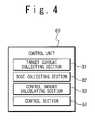
- FIG. 4is a block diagram showing a control unit in the radiotherapy apparatus of the embodiment.
- FIG. 5is a graph showing fluctuation of a 10 cm-depth absorbed dose in a comparison example and fluctuation of a 10 cm-depth absorbed dose of a therapeutic radiation generated by the radiotherapy apparatus according to the present invention.
- FIG. 1is a diagram showing the radiotherapy apparatus 3 according to an embodiment of the present invention.
- the radiotherapy apparatus 3includes a rotation driving unit 11 , an O-ring 12 , a traveling gantry 14 , a swinging mechanism 15 , and an irradiating head 16 .
- the rotation driving unit 11supports the O-ring 12 on a base rotatably around a rotational axis 17 , rotates the O-ring 12 around the rotational axis 17 under the control of a controller of the radiotherapy apparatus (not shown), and outputs a rotation angle of the O-ring 12 to the base.
- the rotational axis 17is parallel to a vertical direction.
- the O-ring 12is formed in a ring shape around a rotational axis 18 , and supports the traveling gantry 14 rotatably around the rotational axis 18 .
- the rotational axis 18is perpendicular to the vertical direction, and extends through an isocenter 19 included in the rotational axis 17 .
- the rotational axis 18is further fixed to the O-ring 12 , and, for this reason, rotates with the O-ring 12 around the rotational axis 17 .
- the traveling gantry 14is formed in a ring shape around the rotational axis 18 , and is arranged concentrically to the ring of the O-ring 12 .
- the radiotherapy apparatus 3further includes a traveling drive unit (not shown).
- the traveling drive unitrotates the traveling gantry 14 around the rotational axis 18 under the control of the radiotherapy apparatus controller, and outputs a traveling angle of the traveling gantry 14 to the O-ring 12 .
- the swinging mechanism 15is fixed inside the ring of the traveling gantry 14 , and supports the irradiating head 16 on the traveling gantry 14 so that the irradiating head 16 can be arranged inside the traveling gantry 14 .
- the swinging mechanism 15has a pan axis 21 and a tilt axis 22 .
- the pan axis 21is fixed to the traveling gantry 14 , and is parallel to the rotational axis 18 without intersecting with the rotational axis 18 .
- the tilt axis 22is orthogonal to the pan axis 21 .
- the swinging mechanism 15turns the irradiating head 16 around the pan axis 21 under the control of the radiotherapy apparatus controller, and turns the irradiating head 16 around the tilt axis 22 .
- the irradiating head 16irradiates a therapeutic radiation 23 under the control of the radiotherapy apparatus controller.
- the therapeutic radiation 23is irradiated almost along a straight line extending through an intersection at which the pan axis 21 and the tilt axis 22 intersect with each other.
- the therapeutic radiation 23has a uniform distribution of intensity. Further, a shape of an irradiation field when the therapeutic radiation 23 is irradiated to a patient is controlled by shielding a part of the therapeutic radiation 23 .
- the therapeutic radiation 23By supporting the irradiating head 16 by the traveling gantry 14 as described above and adjusting the irradiating head 16 by the swinging mechanism 15 once to face the isocenter 19 , the therapeutic radiation 23 always passes through the isocenter 19 even when the O-ring 12 is rotated by the rotation driving unit 11 or the traveling gantry 14 is traveled by the traveling driving unit. That is, the therapeutic radiation 23 can be irradiated to the isocenter 19 from an arbitrary direction by the traveling and the rotating.
- the radiotherapy apparatus 3further includes a plurality of imager systems. That is, the radiotherapy apparatus 3 includes diagnostic X-ray sources 24 and 25 and sensor arrays 32 and 33 .
- the diagnostic X-ray source 24is supported by the traveling gantry 14 .
- the diagnostic X-ray source 24is provided inside the ring of the traveling gantry 14 .
- the diagnostic X-ray source 24is arranged at a position at which an angle between a line connecting the isocenter 19 and the diagnostic X-ray source 24 and a line connecting the isocenter 19 and the irradiating head 16 is an acute angle.
- the diagnostic X-ray source 24irradiates a diagnostic X-ray 35 to the isocenter 19 under the control of the radiotherapy apparatus controller.
- the diagnostic X-ray 35is a conical corn beam that is irradiated from one point included in the diagnostic X-ray source 24 .
- the diagnostic X-ray source 25is supported by the traveling gantry 14 .
- the diagnostic X-ray source 25is provided inside the ring of the traveling gantry 14 , and is arranged at a position at which an angle between a line connecting the isocenter 19 and the diagnostic X-ray source 25 and the line connecting the isocenter 19 and the irradiating head 16 is an acute angle.
- the diagnostic X-ray source 25irradiates a diagnostic X-ray 36 to the isocenter 19 under the control of the radiotherapy apparatus controller.
- the diagnostic X-ray 36is a conical corn beam that is irradiated from one point included in the diagnostic X-ray source 25 .
- the sensor array 32is supported by the traveling gantry 14 .
- the sensor array 32receives the diagnostic X-ray 35 that is irradiated by the diagnostic X-ray source 24 and transmits a target around the isocenter 19 , and produces a transmission image of the target.
- the sensor array 33is supported by the traveling gantry 14 .
- the sensor array 33receives the diagnostic X-ray 36 that is irradiated by the diagnostic X-ray source 25 and transmitted the target around the isocenter 19 , and produces a transmission image of the target.
- a FPDFluor
- X-ray IIImage Intensifier
- transmission images around the isocenter 19can be produced on the basis of image signals obtained by the sensor arrays 32 and 33 .
- the radiotherapy apparatus 3further includes a sensor array 31 .
- the sensor array 31is arranged so that a line connecting the sensor array 31 and the therapeutic radiation irradiating head 16 passes through the isocenter 19 , and is fixed inside the ring of the traveling gantry 14 .
- the sensor array 31receives the therapeutic radiation 23 that is irradiated by the irradiating head 16 and transmits the target around the isocenter 19 , and produces a transmission image of the target.
- the FPDFull Panel Detector
- X-ray IIImage Intensifier
- the radiotherapy apparatus 3further include a couch 41 and a couch driving unit 42 .
- a patient 43 to be treated by the radiotherapy apparatus 3is laid on the couch 41 .
- the couch 41includes holding fixtures (not shown). The holding fixtures fix the patient to the couch 41 so that the patient cannot move.
- the couch driving unit 42supports the couch 41 on the base, and moves the couch 41 under the control of the radiotherapy apparatus controller.
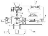
- FIG. 2is a diagram showing the irradiating head 16 .
- the irradiating head 16includes an electron gun 51 , an acceleration tube 52 , an X-ray target 53 , a flattening filter 54 , and a multi-leaf collimator 55 .
- the electron gun 51includes a cathode 61 and a grid 62 .
- the cathode 61is heated by using a supplied electric power such that electrons can be easily emitted.
- the grid 62is applied with a positive voltage so as for the electrons emitted from the cathode 61 to be led to the acceleration tube 52 .
- the acceleration tube 52accelerates the electrons emitted from the electron gun 51 by using supplied high-frequency power, to generate an electron beam and irradiates the electron beam to the X-ray target 53 .
- the X-ray target 53is formed of a material having higher atomic number. Tungsten, tungsten alloy, gold, and tantalum are exemplified as the material having the higher atomic number.
- the X-ray target 53generates a radiation (X-ray) due to the bremsstrahlung effect caused when the electron beam generated by the acceleration tube 52 is irradiated. The radiation is irradiated almost along a straight line passing through a virtual point radiation source that is a point included internally in the X-ray target 53 .
- the flattening filter 54is formed of aluminum and the like, and is a plate having an approximately conical projection. The projection is arranged on an X-ray target 53 side.
- the flattening filter 54is formed such that a dose of the radiation in a predetermined area of a plane perpendicular to its irradiation direction after the radiation irradiated from the X-ray target 53 passes the flattening filter 54 is almost uniformly distributed.
- the multi-leaf collimator 55controls the shape of the irradiation field under the control of the radiotherapy apparatus controller such that a part of the therapeutic radiation 23 transmitted through the flattening filter 54 and then irradiated to the patient is shielded.
- the radiotherapy apparatus 3further includes a transmission type dosimeter 56 , a sensor 57 , an electric gun power supply 58 , a klystron 59 , and a control unit 60 .
- the transmission type dosimeter 56 , the sensor 57 , the electric gun power supply 58 , and the klystron 59are connected to the control unit 60 to communicate with the control unit 60 .
- the transmission type dosimeter 56is arranged in such a manner that the radiation transmits the flattening filter 54 and then transmits the dosimeter 56 .
- the transmission type dosimeter 56includes a gas medium which can be ionized by the X-ray, electrodes between which a high voltage is applied, and a container including the gas medium and the electrodes thereinside.
- the transmission type dosimeter 56measures a dose of the transmitted radiation on the basis of a current flowing between the electrodes, and outputs the measured dose to the control unit 60 .
- the sensor 57measures an electric current flowing through the X-ray target 53 when the electron beam generated by the acceleration tube 52 is irradiated to the X-ray target 53 , and outputs the measured electric current to the control unit 60 .
- the electric gun power supply 58is connected to the electron gun 51 .
- the electric gun power supply 58supplies predetermined electric power to the cathode 61 of the electron gun 51 under the control of the control unit 60 and applies a predetermined voltage to the grid 62 of the electron gun 51 .
- the klystron 59is connected to the acceleration tube 52 via a wave guide tube.
- the klystron 59supplies the high-frequency power to the acceleration tube 52 via the wave guide tube under the control of the control unit 60 .
- the high-frequency powerincludes periodical pulses.
- the pulses of microwavesare formed.
- the klystron 59can be replaced with another high-frequency power supply.
- a magnetron and a multi-electrode tubeare exemplified as the high-frequency source.
- the control unit 60is a computer, and includes a CPU, a storage unit, an input unit, an output unit, and an interface (not shown).
- the CPUexecutes a computer program installed in the control unit 60 , and controls the storage unit, the input unit, the output unit, and the interface.
- the storage unitstores the computer program and temporarily stores data produced by the CPU.
- the input unitproduces data due to a user operation and outputs the produced data to the CPU.
- a keyboardis exemplified as the input unit.
- the output unitoutputs data produced by the CPU so that the data can be recognized by the user.
- a displayis exemplified as the output unit.
- the interfaceoutputs data produced by external equipment connected with the control unit 60 to the CPU, and outputs data produced by the CPU to the external equipment.
- the external equipmentincludes the transmission type dosimeter 56 , the sensor 57 , the electron gun power supply 58 , and the klystron 59 .
- the radiotherapy apparatus 3further includes a de-Qing circuit 71 and a charging element 72 .
- the charging element 72is provided in the course of the wave guide tube connecting the klystron 59 to the acceleration tube 52 .
- the charging element 72is formed from a capacitor.
- the de-Qing circuit 71includes a charging choke coil 73 , a voltage monitor 74 , a secondary coil 75 , a resistor 76 , and a thyristor 77 .
- the charging choke coil 73is provided in the course of the wave guide tube between the klystron 59 and the charging element 72 .
- the charging choke coil 73is formed from an inductance element.
- the voltage monitor 74measures a voltage of a node between the charging choke coil 73 and the de-Qing circuit 71 , and outputs an electric signal when the measured voltage exceeds a predetermined voltage.
- the secondary coil 75 , the resistor 76 , and the thyristor 77form a closed circuit.
- the secondary coil 75is a secondary coil of the charging choke coil 73 .
- the thyristor 77forms the closed circuit when the voltage monitor 74 outputs the electric signal, and opens the circuit when the voltage monitor 74 does not output the electric signal.
- the inductance of the charging choke coil 73changes when a voltage of the high-frequency power supplied from the klystron 59 to the acceleration tube 52 exceeds a predetermined voltage, and thus the high-frequency power is prevented from being supplied to the acceleration tube 52 .
- the voltage of the high-frequency power supplied from the klystron 59 to the acceleration tube 52is made constant. For this reason, a voltage in the acceleration tube 52 for accelerating electrons emitted by the electron gun 51 is controlled to be constant in an analog-like way, and energy applied by the acceleration tube 52 to the electrons emitted by the electron gun 51 becomes constant.
- the computer program installed in the control unit 60includes a target current collecting section 81 , a dose collecting section 82 , a control amount calculating section 83 , and a control section 84 .
- the target current collecting section 81controls the sensor 57 to measures an electric current flowing through the target 53 , and to output the measured current value.
- the dose collecting section 82controls the transmission type dosimeter 56 to measure a dose of a radiation transmitted the transmission type dosimeter 56 , and to output the measured dose.
- the control amount calculating section 83calculates a control amount on the basis of the measured current value outputted from the target current collecting section 81 and the measured dose outputted from the dose collection part 82 .
- the control amountshows a quotient calculated by dividing the measured electric current by the measured dose.
- the control section 84controls the electric gun power supply 58 in a feedback manner so that the control amount calculated by the control amount calculating section 83 can become a predetermined constant value. That is, the control section 84 updates electric power supplied to the cathode 61 of the electron gun 51 by controlling the electric gun power supply 58 so that the control amount calculated by the control amount calculating section 83 can become a predetermined constant value.
- a radiation irradiating methodis carried out by using the radiotherapy apparatus 3 .
- a userfirstly creates a therapy plan.
- the therapy planshows irradiation angles at which the therapeutic radiation 23 is irradiated to the affected region of the patient 43 and shows dose and property of the therapeutic radiation 23 irradiated from the respective irradiation angles.
- the userfixes the patient 43 to the couch 41 of the radiotherapy apparatus 3 .
- the controller of the radiotherapy apparatus 3adjusts positions of the irradiating head 16 and the patient 43 by using the rotation driving unit 11 , the traveling drive unit, and the couch driving unit 42 so that the therapeutic radiation 23 can be irradiated to the patient 43 at the irradiation angles shown by the therapy plan.
- the radiotherapy apparatus controllerrepeatedly performs a tracking operation and the irradiating operation.
- the radiotherapy apparatus controllercalculates a position of the affected region on the basis of images taken by the imager system of the radiotherapy apparatus 3 .
- the radiotherapy apparatus control unitdrives, by using the swinging mechanism 15 , the irradiating head 16 so that the therapeutic radiation 23 can be transmitted through the affected region.
- the radiotherapy apparatus control unit 60irradiates, by using the irradiating head 16 , the therapeutic radiation 23 to the affected region immediately after the irradiating head 16 is moved by the tracking operation.
- the control unit 60collects the electric current flowing through the target 53 from the sensor 57 during the irradiating operation, and collects a dose of the radiation transmitted the transmission type dosimeter 56 from the transmission type dosimeter 56 .
- the control unit 60calculates the control amount based on the collected electric current and dose.
- the control amountshows a quotient calculated by dividing the collected electric current by the collected dose.
- the control unit 60updates the electric power supplied to the cathode 61 of the electron gun 51 by controlling the electric gun power supply 58 in a feedback manner so that the calculated control amount can become a predetermined constant value.
- the expressions (3) and (4)show that the X-ray absorption does “Dose” to the affected region of the patient 43 becomes constant when a quotient S d /S t calculated by dividing the dose S d by the electric current S t is controlled to be constant and that the X-ray absorption dose of the therapeutic radiation 23 becomes constant, which is generated by the radiotherapy apparatus 3 and absorbed in the affected region of the patient 43 .
- the radiotherapy apparatus 3can irradiate only a predetermined dose of the therapeutic radiation to the affected region of the patient 43 more accurately because the fluctuation of the X-ray absorption dose in the therapeutic radiation 23 absorbed by the patient 43 is small.
- FIG. 5shows a fluctuation of a 10 cm-depth absorbed dose of a therapeutic radiation generated by a comparison example of a radiotherapy apparatus according to the present invention.
- the control unit 60 in the radiotherapy apparatus 3 according to the aforementioned embodimentis replaced by another controller.
- a pulse width of a pulse of the high-frequency power generated by the klystron 59is controlled so that a dose measured by the transmission type dosimeter 56 is constant.
- the 10 cm-depth absorption doseis generally equivalent to a dose of the X-ray absorbed in a human body, and a measuring method thereof is well known.
- the fluctuation 86shows that a dose of the therapeutic radiation changes depending on a change of environment that the radiotherapy apparatus is provided and that dispersion (the standard deviation) of the 10 cm-depth absorbed dose of the therapeutic radiation is relatively high.
- FIG. 5further shows a fluctuation of the 10 cm-depth absorbed dose of the therapeutic radiation generated by the radiotherapy apparatus 3 according to the present invention.
- the fluctuation 87shows that the dispersion of the 10 cm-depth absorbed dose is low compared to the fluctuation 86 . That is, the fluctuation 87 shows that the radiotherapy apparatus 3 according to the present invention can irradiate only a predetermined dose of the therapeutic radiation to the affected region of the patient 43 more accurately, compared to the comparison example.
- control section 84 of the control unit 60 according to the aforementioned embodimentis replaced by another control section.
- the control sectioncontrols the electron gun power supply 58 in the feedback manner so that the control amount calculated by the control amount calculating section 83 can be a predetermined constant value, and updates a voltage applied to the grid 62 of the electron gun 51 .
- the above-described radiotherapy apparatuscan reduce the fluctuation of the X-ray absorption dose of the therapeutic radiation 23 absorbed in the affected region of the patient 43 and can irradiate only a predetermined dose of the therapeutic radiation to the affected region more accurately in the same manner as that of the radiotherapy apparatus 3 according to the aforementioned embodiment.
- control sectioncontrols the electron gun power supply 58 in the feedback manner so that the control amount calculated by the control amount calculating section 83 can be a predetermined constant value, and also can updates both of the electric power supplied to the cathode 61 of the electron gun 51 and the voltage applied to the grid 62 .
- This radiotherapy apparatuscan reduce the fluctuation of the X-ray absorption dose of the therapeutic radiation 23 absorbed in the affected region in the body of the patient 43 and can irradiate only a predetermined dose of the therapeutic radiation to the affected region more accurately in the same manner as that of the radiotherapy apparatus 3 according to the aforementioned embodiment.
- control section 84 of the control unit 60is replaced by another control section.
- the control sectioncontrols the klystron 59 in the feedback manner so that the control amount calculated by the control amount calculating section 83 can be a predetermined constant value, and updates a pulse width of a pulse of the high-frequency power supplied to the acceleration tube 52 .
- the control sectionfurther controls the electron gun power supply 58 to supply constant electric power to the cathode 61 of the electron gun 51 and to apply a constant voltage to the grid 62 of the electron gun 51 .
- This radiotherapy apparatuscan reduce the fluctuation of the X-ray absorption dose of the therapeutic radiation 23 absorbed in the affected region in the body of the patient 43 and can irradiate only a predetermined dose of the therapeutic radiation to the affected region more accurately in the same manner as that of the radiotherapy apparatus 3 according to the aforementioned embodiment.
- control sectionalso can control the electron gun power supply 58 in the feedback manner so that the electric current measured by the sensor 57 can be constant, and update the electric power supplied to the cathode 61 of the electron gun 51 or update the voltage applied to the grid 62 of the electron gun 51 .
- the radiotherapy apparatusfurther includes a sensor for measuring an electric current flowing between the cathode 61 and grid 62 of the electron gun 51 .
- the control sectioncan control the electron gun power supply 58 in the feedback manner so that the electric current measured by the sensor can be constant, and update the electric power supplied to the cathode 61 of the electron gun 51 or update the voltage applied to the grid 62 of the electron gun 51 .
- the radiotherapy apparatuscan reduce the fluctuation of the X-ray absorption dose of the therapeutic radiation 23 absorbed in the affected region in the body of the patient 43 and can irradiate only a predetermined dose of the therapeutic radiation to the affected region more accurately in the same manner as that of the radiotherapy apparatus 3 according to the aforementioned embodiment.
Landscapes
- Health & Medical Sciences (AREA)
- Engineering & Computer Science (AREA)
- Biomedical Technology (AREA)
- Pathology (AREA)
- Nuclear Medicine, Radiotherapy & Molecular Imaging (AREA)
- Radiology & Medical Imaging (AREA)
- Life Sciences & Earth Sciences (AREA)
- Animal Behavior & Ethology (AREA)
- General Health & Medical Sciences (AREA)
- Public Health (AREA)
- Veterinary Medicine (AREA)
- Radiation-Therapy Devices (AREA)
Abstract
Description
Rx-ray=k1×St×ft(Eeb) (1)
where k1is a constant, and the ft(Eeb) is a function specific to the
Sd=k2×Rx-ray×fd(Ex-ray) (2),
where k2is a constant, the Ex-rayis an X-ray energy distribution of the X-ray emitted from the
ft(Eeb)×fd(Ex-ray)=1/(k1×k2)×Sd/St (3)
It is known that an X-ray absorption dose “Dose” absorbed by the affected region of the
Dose=k3×Sd×f(Ex-ray) (4)
where k3is a constant, the f (Ex-ray) is a function specific to the patient43 which shows a proportion of the X-ray absorbed by the patient43 when the X-ray having the X-ray energy distribution Ex-rayis irradiated to the
Claims (17)
Applications Claiming Priority (2)
| Application Number | Priority Date | Filing Date | Title |
|---|---|---|---|
| JP2008-203155 | 2008-08-06 | ||
| JP2008203155AJP4691587B2 (en) | 2008-08-06 | 2008-08-06 | Radiotherapy apparatus and radiation irradiation method |
Publications (2)
| Publication Number | Publication Date |
|---|---|
| US20100034352A1 US20100034352A1 (en) | 2010-02-11 |
| US7881431B2true US7881431B2 (en) | 2011-02-01 |
Family
ID=41226418
Family Applications (1)
| Application Number | Title | Priority Date | Filing Date |
|---|---|---|---|
| US12/366,385ActiveUS7881431B2 (en) | 2008-08-06 | 2009-02-05 | Radiotherapy apparatus and radiation irradiating method |
Country Status (5)
| Country | Link |
|---|---|
| US (1) | US7881431B2 (en) |
| EP (1) | EP2151262B1 (en) |
| JP (1) | JP4691587B2 (en) |
| CN (1) | CN101642605B (en) |
| DE (1) | DE602009001154D1 (en) |
Cited By (31)
| Publication number | Priority date | Publication date | Assignee | Title |
|---|---|---|---|---|
| US20070076846A1 (en)* | 2005-07-22 | 2007-04-05 | Ruchala Kenneth J | System and method of delivering radiation therapy to a moving region of interest |
| US20090041200A1 (en)* | 2005-07-23 | 2009-02-12 | Tomotherapy Incorporated | Radiation therapy imaging and delivery utilizing coordinated motion of jaws, gantry, and couch |
| US20090140671A1 (en)* | 2007-11-30 | 2009-06-04 | O'neal Iii Charles D | Matching a resonant frequency of a resonant cavity to a frequency of an input voltage |
| US20090200483A1 (en)* | 2005-11-18 | 2009-08-13 | Still River Systems Incorporated | Inner Gantry |
| US20100045213A1 (en)* | 2004-07-21 | 2010-02-25 | Still River Systems, Inc. | Programmable Radio Frequency Waveform Generator for a Synchrocyclotron |
| US8581523B2 (en) | 2007-11-30 | 2013-11-12 | Mevion Medical Systems, Inc. | Interrupted particle source |
| US8791656B1 (en) | 2013-05-31 | 2014-07-29 | Mevion Medical Systems, Inc. | Active return system |
| US8927950B2 (en) | 2012-09-28 | 2015-01-06 | Mevion Medical Systems, Inc. | Focusing a particle beam |
| US9155186B2 (en) | 2012-09-28 | 2015-10-06 | Mevion Medical Systems, Inc. | Focusing a particle beam using magnetic field flutter |
| US9185789B2 (en) | 2012-09-28 | 2015-11-10 | Mevion Medical Systems, Inc. | Magnetic shims to alter magnetic fields |
| US9301384B2 (en) | 2012-09-28 | 2016-03-29 | Mevion Medical Systems, Inc. | Adjusting energy of a particle beam |
| US9443633B2 (en) | 2013-02-26 | 2016-09-13 | Accuray Incorporated | Electromagnetically actuated multi-leaf collimator |
| US9545528B2 (en) | 2012-09-28 | 2017-01-17 | Mevion Medical Systems, Inc. | Controlling particle therapy |
| US9622335B2 (en) | 2012-09-28 | 2017-04-11 | Mevion Medical Systems, Inc. | Magnetic field regenerator |
| US9661736B2 (en) | 2014-02-20 | 2017-05-23 | Mevion Medical Systems, Inc. | Scanning system for a particle therapy system |
| US9681531B2 (en) | 2012-09-28 | 2017-06-13 | Mevion Medical Systems, Inc. | Control system for a particle accelerator |
| US9723705B2 (en) | 2012-09-28 | 2017-08-01 | Mevion Medical Systems, Inc. | Controlling intensity of a particle beam |
| US9730308B2 (en) | 2013-06-12 | 2017-08-08 | Mevion Medical Systems, Inc. | Particle accelerator that produces charged particles having variable energies |
| US9731148B2 (en) | 2005-07-23 | 2017-08-15 | Tomotherapy Incorporated | Radiation therapy imaging and delivery utilizing coordinated motion of gantry and couch |
| US9950194B2 (en) | 2014-09-09 | 2018-04-24 | Mevion Medical Systems, Inc. | Patient positioning system |
| US9962560B2 (en) | 2013-12-20 | 2018-05-08 | Mevion Medical Systems, Inc. | Collimator and energy degrader |
| US10254739B2 (en) | 2012-09-28 | 2019-04-09 | Mevion Medical Systems, Inc. | Coil positioning system |
| US10258810B2 (en) | 2013-09-27 | 2019-04-16 | Mevion Medical Systems, Inc. | Particle beam scanning |
| US10463926B2 (en) | 2016-06-30 | 2019-11-05 | Taylor Made Golf Company, Inc. | Golf club head |
| US10518143B1 (en) | 2018-06-19 | 2019-12-31 | Taylor Made Golf Company, Inc. | Golf club head |
| US10646728B2 (en) | 2015-11-10 | 2020-05-12 | Mevion Medical Systems, Inc. | Adaptive aperture |
| US10653892B2 (en) | 2017-06-30 | 2020-05-19 | Mevion Medical Systems, Inc. | Configurable collimator controlled using linear motors |
| US10675487B2 (en) | 2013-12-20 | 2020-06-09 | Mevion Medical Systems, Inc. | Energy degrader enabling high-speed energy switching |
| US10925147B2 (en) | 2016-07-08 | 2021-02-16 | Mevion Medical Systems, Inc. | Treatment planning |
| US11103730B2 (en) | 2017-02-23 | 2021-08-31 | Mevion Medical Systems, Inc. | Automated treatment in particle therapy |
| US11291861B2 (en) | 2019-03-08 | 2022-04-05 | Mevion Medical Systems, Inc. | Delivery of radiation by column and generating a treatment plan therefor |
Families Citing this family (14)
| Publication number | Priority date | Publication date | Assignee | Title |
|---|---|---|---|---|
| JP6060086B2 (en)* | 2010-11-09 | 2017-01-11 | コーニンクレッカ フィリップス エヌ ヴェKoninklijke Philips N.V. | Magnetic resonance imaging and radiotherapy apparatus having at least two transmission / reception channels |
| JP5497911B2 (en) | 2010-11-12 | 2014-05-21 | Jx日鉱日石金属株式会社 | Circuit forming method on flexible laminate substrate |
| US20120229024A1 (en)* | 2011-03-10 | 2012-09-13 | Elekta Ab (Publ) | Electron source for linear accelerators |
| JP2012209119A (en)* | 2011-03-29 | 2012-10-25 | Mitsubishi Heavy Ind Ltd | X-ray generator and control method thereof |
| US20130023716A1 (en)* | 2011-04-25 | 2013-01-24 | Mark Thomas | Dose control system and method of controlling output dose of a radiation therapy treatment system |
| DE102012200616B4 (en)* | 2012-01-17 | 2013-10-10 | Siemens Aktiengesellschaft | Dose monitoring and X-ray device |
| WO2014018976A1 (en)* | 2012-07-27 | 2014-01-30 | H. Lee Moffitt Cancer Center And Research Institute, Inc. | Multi-spectral fluorescence for in-vivo determination of proton energy and range in proton therapy |
| US20140169519A1 (en)* | 2012-12-18 | 2014-06-19 | Elekta Ab (Publ) | Cone-beam CT Scanning |
| FR3013225B1 (en)* | 2013-11-20 | 2018-09-14 | Pmb | IONIZING RADIATION IRRADIATION DEVICE, IN PARTICULAR FOR RADIOTHERAPY AND / OR RADIOBIOLOGY |
| JP6530933B2 (en)* | 2015-03-19 | 2019-06-12 | 株式会社日立製作所 | Radiation therapy apparatus control apparatus, radiation therapy system, radiation therapy apparatus control method and program |
| US11364392B2 (en) | 2016-02-18 | 2022-06-21 | Convergent R.N.R Ltd. | Method of evaluating a dose as function of depth for nonuniform X-ray beams |
| WO2017141245A1 (en)* | 2016-02-18 | 2017-08-24 | Convergent R.N.R Ltd. | Method of evaluating a dose as function of depth for non-uniform x-ray beams |
| CN107456663A (en) | 2017-07-19 | 2017-12-12 | 西安大医数码技术有限公司 | A kind of focus method of X ray, device and radiotherapy apparatus |
| US12303719B2 (en)* | 2021-08-17 | 2025-05-20 | Varian Medical Systems, Inc. | Movable/replaceable high intensity target and multiple accelerator systems and methods |
Citations (9)
| Publication number | Priority date | Publication date | Assignee | Title |
|---|---|---|---|---|
| US4427890A (en) | 1981-08-03 | 1984-01-24 | Siemens Medical Laboratories, Inc. | Dose monitor chamber for electron or X-ray radiation |
| JPH0684664U (en) | 1993-05-17 | 1994-12-02 | 横河電機株式会社 | X-ray tube with deterioration detection function |
| WO2003101298A2 (en) | 2002-05-31 | 2003-12-11 | Info & Tech S.R.L. | Machine for intraoperative radiation therapy |
| JP2004321408A (en) | 2003-04-23 | 2004-11-18 | Mitsubishi Electric Corp | Radiation irradiation device and radiation irradiation method |
| US20040247080A1 (en)* | 2003-03-04 | 2004-12-09 | Feda Francis Michael | Systems and methods for controlling an X-ray source |
| EP1530408A2 (en) | 2003-11-06 | 2005-05-11 | feinfocus Röntgen-Systeme GmbH | Microfocus x-ray system |
| JP2005340009A (en) | 2004-05-27 | 2005-12-08 | Shimadzu Corp | X-ray generation control method and apparatus |
| US20070248214A1 (en)* | 2006-04-25 | 2007-10-25 | Accuray Incorporated | Energy monitoring target for x-ray dose-rate control |
| JP2008027360A (en) | 2006-07-25 | 2008-02-07 | Toshiba Corp | Control circuit |
- 2008
- 2008-08-06JPJP2008203155Apatent/JP4691587B2/enactiveActive
- 2009
- 2009-02-05EPEP09152178Apatent/EP2151262B1/enactiveActive
- 2009-02-05USUS12/366,385patent/US7881431B2/enactiveActive
- 2009-02-05DEDE602009001154Tpatent/DE602009001154D1/enactiveActive
- 2009-02-09CNCN2009100070484Apatent/CN101642605B/enactiveActive
Patent Citations (10)
| Publication number | Priority date | Publication date | Assignee | Title |
|---|---|---|---|---|
| US4427890A (en) | 1981-08-03 | 1984-01-24 | Siemens Medical Laboratories, Inc. | Dose monitor chamber for electron or X-ray radiation |
| JPH0684664U (en) | 1993-05-17 | 1994-12-02 | 横河電機株式会社 | X-ray tube with deterioration detection function |
| WO2003101298A2 (en) | 2002-05-31 | 2003-12-11 | Info & Tech S.R.L. | Machine for intraoperative radiation therapy |
| US20040247080A1 (en)* | 2003-03-04 | 2004-12-09 | Feda Francis Michael | Systems and methods for controlling an X-ray source |
| JP2004321408A (en) | 2003-04-23 | 2004-11-18 | Mitsubishi Electric Corp | Radiation irradiation device and radiation irradiation method |
| EP1530408A2 (en) | 2003-11-06 | 2005-05-11 | feinfocus Röntgen-Systeme GmbH | Microfocus x-ray system |
| US20050100133A1 (en) | 2003-11-06 | 2005-05-12 | Alfred Reinhold | Microfocus x-ray apparatus |
| JP2005340009A (en) | 2004-05-27 | 2005-12-08 | Shimadzu Corp | X-ray generation control method and apparatus |
| US20070248214A1 (en)* | 2006-04-25 | 2007-10-25 | Accuray Incorporated | Energy monitoring target for x-ray dose-rate control |
| JP2008027360A (en) | 2006-07-25 | 2008-02-07 | Toshiba Corp | Control circuit |
Non-Patent Citations (1)
| Title |
|---|
| Medduagh, G. E. "The R.F. System of a Typical Clinical Linear Accelerator", IEEE MTT-S Digest, TH3D-2, IEEE MTT-S International, May 23, 1994, XP010586494, pp. 1611-1614. |
Cited By (54)
| Publication number | Priority date | Publication date | Assignee | Title |
|---|---|---|---|---|
| US8952634B2 (en) | 2004-07-21 | 2015-02-10 | Mevion Medical Systems, Inc. | Programmable radio frequency waveform generator for a synchrocyclotron |
| US20100045213A1 (en)* | 2004-07-21 | 2010-02-25 | Still River Systems, Inc. | Programmable Radio Frequency Waveform Generator for a Synchrocyclotron |
| USRE48047E1 (en) | 2004-07-21 | 2020-06-09 | Mevion Medical Systems, Inc. | Programmable radio frequency waveform generator for a synchrocyclotron |
| US8767917B2 (en) | 2005-07-22 | 2014-07-01 | Tomotherapy Incorpoated | System and method of delivering radiation therapy to a moving region of interest |
| US20070076846A1 (en)* | 2005-07-22 | 2007-04-05 | Ruchala Kenneth J | System and method of delivering radiation therapy to a moving region of interest |
| US20090041200A1 (en)* | 2005-07-23 | 2009-02-12 | Tomotherapy Incorporated | Radiation therapy imaging and delivery utilizing coordinated motion of jaws, gantry, and couch |
| US9731148B2 (en) | 2005-07-23 | 2017-08-15 | Tomotherapy Incorporated | Radiation therapy imaging and delivery utilizing coordinated motion of gantry and couch |
| US8907311B2 (en) | 2005-11-18 | 2014-12-09 | Mevion Medical Systems, Inc. | Charged particle radiation therapy |
| US8344340B2 (en) | 2005-11-18 | 2013-01-01 | Mevion Medical Systems, Inc. | Inner gantry |
| US20090200483A1 (en)* | 2005-11-18 | 2009-08-13 | Still River Systems Incorporated | Inner Gantry |
| US8581523B2 (en) | 2007-11-30 | 2013-11-12 | Mevion Medical Systems, Inc. | Interrupted particle source |
| USRE48317E1 (en) | 2007-11-30 | 2020-11-17 | Mevion Medical Systems, Inc. | Interrupted particle source |
| US8933650B2 (en) | 2007-11-30 | 2015-01-13 | Mevion Medical Systems, Inc. | Matching a resonant frequency of a resonant cavity to a frequency of an input voltage |
| US8970137B2 (en) | 2007-11-30 | 2015-03-03 | Mevion Medical Systems, Inc. | Interrupted particle source |
| US20090140671A1 (en)* | 2007-11-30 | 2009-06-04 | O'neal Iii Charles D | Matching a resonant frequency of a resonant cavity to a frequency of an input voltage |
| US9155186B2 (en) | 2012-09-28 | 2015-10-06 | Mevion Medical Systems, Inc. | Focusing a particle beam using magnetic field flutter |
| US9301384B2 (en) | 2012-09-28 | 2016-03-29 | Mevion Medical Systems, Inc. | Adjusting energy of a particle beam |
| US9545528B2 (en) | 2012-09-28 | 2017-01-17 | Mevion Medical Systems, Inc. | Controlling particle therapy |
| US9622335B2 (en) | 2012-09-28 | 2017-04-11 | Mevion Medical Systems, Inc. | Magnetic field regenerator |
| US9185789B2 (en) | 2012-09-28 | 2015-11-10 | Mevion Medical Systems, Inc. | Magnetic shims to alter magnetic fields |
| US9681531B2 (en) | 2012-09-28 | 2017-06-13 | Mevion Medical Systems, Inc. | Control system for a particle accelerator |
| US9706636B2 (en) | 2012-09-28 | 2017-07-11 | Mevion Medical Systems, Inc. | Adjusting energy of a particle beam |
| US9723705B2 (en) | 2012-09-28 | 2017-08-01 | Mevion Medical Systems, Inc. | Controlling intensity of a particle beam |
| US10254739B2 (en) | 2012-09-28 | 2019-04-09 | Mevion Medical Systems, Inc. | Coil positioning system |
| US10155124B2 (en) | 2012-09-28 | 2018-12-18 | Mevion Medical Systems, Inc. | Controlling particle therapy |
| US8927950B2 (en) | 2012-09-28 | 2015-01-06 | Mevion Medical Systems, Inc. | Focusing a particle beam |
| US10368429B2 (en) | 2012-09-28 | 2019-07-30 | Mevion Medical Systems, Inc. | Magnetic field regenerator |
| US9443633B2 (en) | 2013-02-26 | 2016-09-13 | Accuray Incorporated | Electromagnetically actuated multi-leaf collimator |
| US8791656B1 (en) | 2013-05-31 | 2014-07-29 | Mevion Medical Systems, Inc. | Active return system |
| US9730308B2 (en) | 2013-06-12 | 2017-08-08 | Mevion Medical Systems, Inc. | Particle accelerator that produces charged particles having variable energies |
| US10258810B2 (en) | 2013-09-27 | 2019-04-16 | Mevion Medical Systems, Inc. | Particle beam scanning |
| US10456591B2 (en) | 2013-09-27 | 2019-10-29 | Mevion Medical Systems, Inc. | Particle beam scanning |
| US9962560B2 (en) | 2013-12-20 | 2018-05-08 | Mevion Medical Systems, Inc. | Collimator and energy degrader |
| US10675487B2 (en) | 2013-12-20 | 2020-06-09 | Mevion Medical Systems, Inc. | Energy degrader enabling high-speed energy switching |
| US10434331B2 (en) | 2014-02-20 | 2019-10-08 | Mevion Medical Systems, Inc. | Scanning system |
| US11717700B2 (en) | 2014-02-20 | 2023-08-08 | Mevion Medical Systems, Inc. | Scanning system |
| US9661736B2 (en) | 2014-02-20 | 2017-05-23 | Mevion Medical Systems, Inc. | Scanning system for a particle therapy system |
| US9950194B2 (en) | 2014-09-09 | 2018-04-24 | Mevion Medical Systems, Inc. | Patient positioning system |
| US11213697B2 (en) | 2015-11-10 | 2022-01-04 | Mevion Medical Systems, Inc. | Adaptive aperture |
| US10646728B2 (en) | 2015-11-10 | 2020-05-12 | Mevion Medical Systems, Inc. | Adaptive aperture |
| US10786689B2 (en) | 2015-11-10 | 2020-09-29 | Mevion Medical Systems, Inc. | Adaptive aperture |
| US11786754B2 (en) | 2015-11-10 | 2023-10-17 | Mevion Medical Systems, Inc. | Adaptive aperture |
| US10463926B2 (en) | 2016-06-30 | 2019-11-05 | Taylor Made Golf Company, Inc. | Golf club head |
| US10925147B2 (en) | 2016-07-08 | 2021-02-16 | Mevion Medical Systems, Inc. | Treatment planning |
| US12150235B2 (en) | 2016-07-08 | 2024-11-19 | Mevion Medical Systems, Inc. | Treatment planning |
| US11103730B2 (en) | 2017-02-23 | 2021-08-31 | Mevion Medical Systems, Inc. | Automated treatment in particle therapy |
| US10653892B2 (en) | 2017-06-30 | 2020-05-19 | Mevion Medical Systems, Inc. | Configurable collimator controlled using linear motors |
| US10960277B2 (en) | 2018-06-19 | 2021-03-30 | Taylor Made Golf Company, Inc. | Golf club head |
| US10518143B1 (en) | 2018-06-19 | 2019-12-31 | Taylor Made Golf Company, Inc. | Golf club head |
| US11291861B2 (en) | 2019-03-08 | 2022-04-05 | Mevion Medical Systems, Inc. | Delivery of radiation by column and generating a treatment plan therefor |
| US11311746B2 (en) | 2019-03-08 | 2022-04-26 | Mevion Medical Systems, Inc. | Collimator and energy degrader for a particle therapy system |
| US11717703B2 (en) | 2019-03-08 | 2023-08-08 | Mevion Medical Systems, Inc. | Delivery of radiation by column and generating a treatment plan therefor |
| US12161885B2 (en) | 2019-03-08 | 2024-12-10 | Mevion Medical Systems, Inc. | Delivery of radiation by column and generating a treatment plan therefor |
| US12168147B2 (en) | 2019-03-08 | 2024-12-17 | Mevion Medical Systems, Inc. | Collimator and energy degrader for a particle therapy system |
Also Published As
| Publication number | Publication date |
|---|---|
| CN101642605A (en) | 2010-02-10 |
| EP2151262B1 (en) | 2011-04-27 |
| JP2010035863A (en) | 2010-02-18 |
| DE602009001154D1 (en) | 2011-06-09 |
| JP4691587B2 (en) | 2011-06-01 |
| EP2151262A1 (en) | 2010-02-10 |
| US20100034352A1 (en) | 2010-02-11 |
| CN101642605B (en) | 2013-03-06 |
Similar Documents
| Publication | Publication Date | Title |
|---|---|---|
| US7881431B2 (en) | Radiotherapy apparatus and radiation irradiating method | |
| US10806950B2 (en) | Rapid imaging systems and methods for facilitating rapid radiation therapies | |
| US11712585B2 (en) | Systems, methods, and devices for high-energy irradiation | |
| US9018603B2 (en) | Pluridirectional very high electron energy radiation therapy systems and processes | |
| US12420116B2 (en) | Methods and systems for using and controlling higher dose rate ionizing radiation in short time intervals | |
| US6813336B1 (en) | High definition conformal arc radiation therapy with a multi-leaf collimator | |
| US20120041251A1 (en) | Charged particle cancer therapy x-ray method and apparatus | |
| JPWO2012120636A1 (en) | Particle beam therapy apparatus and irradiation dose setting method for particle beam therapy apparatus | |
| JP4495112B2 (en) | Radiotherapy apparatus control apparatus and radiation irradiation method | |
| JPH0928822A (en) | Method and device to adjust emission that is emitted in emission beam generator | |
| JP5906179B2 (en) | Dose distribution measuring device | |
| US8742326B2 (en) | Determination of beam parameters for asymmetrical photon beams | |
| US6639967B2 (en) | Electron gun heating control to reduce the effect of back heating in medical linear accelerators | |
| Hernández | Low-dose ion-based transmission radiography and tomography for optimization of carbon ion-beam therapy | |
| Yoshida et al. | Electron accelerator and beam irradiation system | |
| JP2013138774A (en) | Radiotherapy system | |
| EP4106868B1 (en) | Treatment technique for cardiac targets | |
| CN103007438B (en) | Method and apparatus for determining irradiation duration in the works in particle-irradiation |
Legal Events
| Date | Code | Title | Description |
|---|---|---|---|
| AS | Assignment | Owner name:MITSUBISHI HEAVY INDUSTRIES, LTD.,JAPAN Free format text:ASSIGNMENT OF ASSIGNORS INTEREST;ASSIGNORS:AOI, TATSUFUMI;YAMASHITA, ICHIRO;TSUKUDA, KAZUHIRO;AND OTHERS;REEL/FRAME:022909/0701 Effective date:20090605 Owner name:MITSUBISHI HEAVY INDUSTRIES, LTD., JAPAN Free format text:ASSIGNMENT OF ASSIGNORS INTEREST;ASSIGNORS:AOI, TATSUFUMI;YAMASHITA, ICHIRO;TSUKUDA, KAZUHIRO;AND OTHERS;REEL/FRAME:022909/0701 Effective date:20090605 | |
| FEPP | Fee payment procedure | Free format text:PAYOR NUMBER ASSIGNED (ORIGINAL EVENT CODE: ASPN); ENTITY STATUS OF PATENT OWNER: LARGE ENTITY | |
| STCF | Information on status: patent grant | Free format text:PATENTED CASE | |
| FPAY | Fee payment | Year of fee payment:4 | |
| AS | Assignment | Owner name:HITACHI, LTD., JAPAN Free format text:ASSIGNMENT OF ASSIGNORS INTEREST;ASSIGNOR:MITSUBISHI HEAVY INDUSTRIES, LTD.;REEL/FRAME:042820/0605 Effective date:20170401 | |
| MAFP | Maintenance fee payment | Free format text:PAYMENT OF MAINTENANCE FEE, 8TH YEAR, LARGE ENTITY (ORIGINAL EVENT CODE: M1552) Year of fee payment:8 | |
| MAFP | Maintenance fee payment | Free format text:PAYMENT OF MAINTENANCE FEE, 12TH YEAR, LARGE ENTITY (ORIGINAL EVENT CODE: M1553); ENTITY STATUS OF PATENT OWNER: LARGE ENTITY Year of fee payment:12 | |
| AS | Assignment | Owner name:HITACHI HIGH-TECH CORPORATION, JAPAN Free format text:ASSIGNMENT OF ASSIGNORS INTEREST;ASSIGNOR:HITACHI, LTD.;REEL/FRAME:068292/0514 Effective date:20240401 |