US7880987B2 - Media servowriter/certifier - Google Patents
Media servowriter/certifierDownload PDFInfo
- Publication number
- US7880987B2 US7880987B2US12/016,175US1617508AUS7880987B2US 7880987 B2US7880987 B2US 7880987B2US 1617508 AUS1617508 AUS 1617508AUS 7880987 B2US7880987 B2US 7880987B2
- Authority
- US
- United States
- Prior art keywords
- media
- data
- read
- user data
- servo
- Prior art date
- Legal status (The legal status is an assumption and is not a legal conclusion. Google has not performed a legal analysis and makes no representation as to the accuracy of the status listed.)
- Expired - Fee Related, expires
Links
Images


Classifications
- G—PHYSICS
- G11—INFORMATION STORAGE
- G11B—INFORMATION STORAGE BASED ON RELATIVE MOVEMENT BETWEEN RECORD CARRIER AND TRANSDUCER
- G11B20/00—Signal processing not specific to the method of recording or reproducing; Circuits therefor
- G11B20/10—Digital recording or reproducing
- G11B20/18—Error detection or correction; Testing, e.g. of drop-outs
- G11B20/1816—Testing
- G—PHYSICS
- G11—INFORMATION STORAGE
- G11B—INFORMATION STORAGE BASED ON RELATIVE MOVEMENT BETWEEN RECORD CARRIER AND TRANSDUCER
- G11B5/00—Recording by magnetisation or demagnetisation of a record carrier; Reproducing by magnetic means; Record carriers therefor
- G11B5/48—Disposition or mounting of heads or head supports relative to record carriers ; arrangements of heads, e.g. for scanning the record carrier to increase the relative speed
- G11B5/54—Disposition or mounting of heads or head supports relative to record carriers ; arrangements of heads, e.g. for scanning the record carrier to increase the relative speed with provision for moving the head into or out of its operative position or across tracks
- G11B5/55—Track change, selection or acquisition by displacement of the head
- G11B5/5521—Track change, selection or acquisition by displacement of the head across disk tracks
- G11B5/5526—Control therefor; circuits, track configurations or relative disposition of servo-information transducers and servo-information tracks for control thereof
- G11B5/553—Details
- G11B5/5534—Initialisation, calibration, e.g. cylinder "set-up"
- G—PHYSICS
- G11—INFORMATION STORAGE
- G11B—INFORMATION STORAGE BASED ON RELATIVE MOVEMENT BETWEEN RECORD CARRIER AND TRANSDUCER
- G11B5/00—Recording by magnetisation or demagnetisation of a record carrier; Reproducing by magnetic means; Record carriers therefor
- G11B5/48—Disposition or mounting of heads or head supports relative to record carriers ; arrangements of heads, e.g. for scanning the record carrier to increase the relative speed
- G11B5/58—Disposition or mounting of heads or head supports relative to record carriers ; arrangements of heads, e.g. for scanning the record carrier to increase the relative speed with provision for moving the head for the purpose of maintaining alignment of the head relative to the record carrier during transducing operation, e.g. to compensate for surface irregularities of the latter or for track following
- G11B5/596—Disposition or mounting of heads or head supports relative to record carriers ; arrangements of heads, e.g. for scanning the record carrier to increase the relative speed with provision for moving the head for the purpose of maintaining alignment of the head relative to the record carrier during transducing operation, e.g. to compensate for surface irregularities of the latter or for track following for track following on disks
- G11B5/59633—Servo formatting
- G11B5/59638—Servo formatting apparatuses, e.g. servo-writers
- G—PHYSICS
- G11—INFORMATION STORAGE
- G11B—INFORMATION STORAGE BASED ON RELATIVE MOVEMENT BETWEEN RECORD CARRIER AND TRANSDUCER
- G11B5/00—Recording by magnetisation or demagnetisation of a record carrier; Reproducing by magnetic means; Record carriers therefor
- G11B5/48—Disposition or mounting of heads or head supports relative to record carriers ; arrangements of heads, e.g. for scanning the record carrier to increase the relative speed
- G11B5/58—Disposition or mounting of heads or head supports relative to record carriers ; arrangements of heads, e.g. for scanning the record carrier to increase the relative speed with provision for moving the head for the purpose of maintaining alignment of the head relative to the record carrier during transducing operation, e.g. to compensate for surface irregularities of the latter or for track following
- G11B5/596—Disposition or mounting of heads or head supports relative to record carriers ; arrangements of heads, e.g. for scanning the record carrier to increase the relative speed with provision for moving the head for the purpose of maintaining alignment of the head relative to the record carrier during transducing operation, e.g. to compensate for surface irregularities of the latter or for track following for track following on disks
- G11B5/59633—Servo formatting
- G11B5/59666—Self servo writing
Definitions
- Servo informationis stored to media in a deliberate manner as part of the process of preparing the media for use in a data storage device.
- the servo informationdelineates the storage area in a data storage disc, for example, into addressable locations at the intersection of a designated radial position, such as track number, and a designated rotational position, such as sector number. Pluralities of discrete servo sectors form rings across the storage space, be they concentric or spiral rings.
- a data transfer elementcontinuously feeds the servo information back to a servo control system as the element is moved about in the storage area.
- the control systemutilizes the servo information to position the element, such as in deriving an optimal trajectory for moving the element to a desired track and maintaining the element at the desired track.
- in-situ approachesinclude storing servo data to the disc after it has been installed as a component part of the disc drive.
- the actuator in the disc driveis used to store the servo data to each disc.
- an external positionerengages the actuator and positionally controls it.
- seed datais first stored to the disc and the disc drive then executes programming instructions that propagate the servo data from the seed data (self-servo schemes).
- Ex-situ approachesstore some or all of the servo data to a disc before it is installed in the disc drive.
- Servowriters of this typetypically employ an actuator supporting an element in a data storage relationship with the disc which is mounted on a rotating spindle, similar to the disc drive.
- media certificationis also performed to ensure a requisite quality exists in the media's capability to store data and retain it.
- certificationinvolves writing a preselected user data pattern in the storage area and then analyzing a read signal for indications of flaws in the media.
- a flawmay exist because of nonconformities in the media, or may be due to a presence of contamination or debris. Screening the media for flaws before it escapes the factory or even reaches the finished goods is essential to building the expected quality and reliability into the storage devices.
- Both servowriting and certificationentail carrying out relatively long processes within what is a highly automated and fast paced manufacturing system.
- the claimed embodimentsare directed to improvements in both the effectiveness and the efficiency with which the servowriting and certifying processes are performed.
- an apparatushaving a plurality of data transfer members positionally disposable in a data transfer relationship with a respective plurality of media.
- the apparatusalso has a plurality of read channels, each read channel being dedicated to a respective one of the data transfer members in order to simultaneously process a plurality of individual read signals from each of the plurality of data transfer members to identify flaws in the plurality of media.
- a communication circuitfor a media servowriter/certifier having a controller that is responsive to a timing reference in interleaving a servo data stream and a user data stream into a write signal that stores a full compliment of position servo bursts to a media, and that stores user data configured for certifying the media, both during only one complete pass of the media.
- an apparatushaving a plurality of data transfer members disposed in a data transfer relationship with a respective plurality of data storage media, and means for certifying while servowriting by interleaving streams of servo data and user data and storing the interleaved stream at a first location of each of the plurality of media, while retrieving previously stored user data from a second location of each of the plurality of media, wherein a full compliment of the user data is retrieved from the second location within a timeframe during which a full compliment of the servo data is stored to the first location in a minimum possible number of passes between the plurality of storage media and the plurality of data transfer members.
- FIG. 1is an isometric view of a media servowriter/certifier apparatus constructed in accordance with the claimed embodiments.
- FIG. 2is a plan view of the apparatus of FIG. 1 .
- FIG. 3is an isometric view of a portion of the apparatus of FIG. 1 .
- FIG. 4is a diagrammatic depiction of a manner in which servo wedges and data wedges can be arranged on a disc.
- FIG. 5is a diagrammatic depiction of an illustrative formatted servo sector.
- FIG. 6graphically depicts a 2T oscillating reference waveform in NRZ format and a respective analog read signal indicating a media flaw.
- FIG. 7is an isometric view of disc drive which has in-situ flaw scan processing capabilities.
- FIG. 8is a functional block diagram of the read/write channel of the disc drive of FIG. 7 .
- FIG. 9is a functional block diagram of the plurality of dedicated read channels in the media servowriter/certifier apparatus of FIG. 1 .
- FIG. 10is a generalized functional depiction of the media servowriter/certifier apparatus of FIG. 1 .
- FIG. 11is a diagrammatic depiction of the communication bus of the media servowriter/certifier depicted in FIG. 10 .
- FIGS. 12 and 13depict tabulated results of the flaw scan processing capability of the media servowriter/certifier depicted in FIG. 10 .
- FIG. 14is a functional block depiction of a user data write channel and a servo data write channel that are capable of varying the bit stream density across.
- FIG. 15diagrammatically depicts a desired read channel being made part of a daughter card that is plugged into the media servowriter/certifier control board.
- FIGS. 16-23diagrammatically depict a method of certifying media while servowriting to the media in accordance with embodiments of the present invention.
- FIGS. 1-3are views of a media servowriter/certifier apparatus 100 that is constructed in accordance with the claimed embodiments.
- an actuator assembly 102has a motor 101 that rotatably positions an actuator 103 that, in turn, supports a plurality of data transfer elements 104 , such as transducers, at a distal end thereof.
- Host access commandsare executed by the apparatus 100 to simultaneously store data to and retrieve data from a plurality of data storage discs 106 .
- Electronics controlling the functions of the apparatus 100reside in a control board 108 , and signals are communicated between the control board 108 and the transducers 104 by a printed circuit cable assembly 110 .
- the actuator assembly 102has a base that is floatably supported upon a translational gas bearing (not depicted), and moved thereupon by a slide 111 .
- a vacuum chuck 112fixes the base at a desired location for precise lateral positioning of the transducers 104 .
- a spindle assembly 116presents the batch of discs 106 to the actuator assembly 102 , rotating them in a data transfer relationship with the transducers 104 . Note that in FIG. 3 the spindle assembly 116 is not shown for clarity sake. All these assemblies are supported upon a substantially immobile base 118 that is resistant to movement, such as a granite slab.
- FIG. 1depicts the apparatus 100 in a load/unload mode whereby the actuator assembly 102 is moved away from the spindle assembly 116 via the slide 111 and translational bearing, and a shroud 120 is pivoted away from an operable position where it partially encloses the discs 106 .
- Thispermits unloading a batch of processed discs 106 from the spindle assembly 116 , and then loading a next batch of discs 106 to be processed.
- the discs 106are supported on a removable hub having a clamp 122 at one end thereof for fixing the discs 106 in rotation, and having a quick connect feature 124 at the other end thereof for mounting the hub to the spindle assembly 116 .
- the apparatus 100is returned to the operational mode depicted in FIG. 3 .
- a comb 126pivots toward the discs 106 to spreadingly engage the suspension members supporting the transducers 104 , thereby creating a clearance between opposing transducers 104 sufficient for merging the discs 106 with the actuator 103 . After merging, the comb 126 clearingly pivots away from the discs 106 .
- Servowritingthen begins by spinning the discs 106 and rotating the actuator 103 to present the transducers 104 to various storage locations of the respective discs 106 .
- the instantaneous lateral position of the transducers 104is measured by an interferometer 114 , which provides position signals to the control system controlling the motor 101 and the slide 111 .
- FIGS. 4 and 5generally depict a manner in which the servo data is arranged on the disc 106 by the servowriting.
- a number of servo data wedges 130radially span the disc 106 like spokes in a wheel.
- Each servo wedge 130is formed by storing a servo field 132 at each of a plurality of data tracks 134 (only one track 134 depicted), the tracks 134 being either concentric or spiral shaped data storage portions of the disc 106 .
- the total number of servo wedges 130 per track 134depends on the servo sampling rate of the device ultimately using the disc 106 . Generally, the number varies from about 100 to 300 servo wedges 130 per data track 134 .
- User data wedges 136are defined between adjacent pairs of the servo wedges 130 .
- the apparatus 100formats only the servo wedges 130 during the servowriting process. That is, the user data wedges 136 remain in the form of unformatted data storage space between adjacent servo wedges 130 .
- the user data wedges 136are formatted as well to store user data in fixed size addressable blocks, such as 512 bytes each.
- each servo field 132includes an automatic gain control (AGC) field 138 , a synchronization (S) field 140 , an index (I) field 142 , a Gray code (GC) field 144 , and a position field (POS) 146 .
- the AGC field 138provides an oscillating preamble signal to prepare servo control circuitry for receipt of the remaining servo data.
- the synchronization field 140signals the presence of a particular servo data wedge 130 by storing a unique synchronization pattern that is a selected Hamming distance away from other possible combinations of bit patterns on the disc.
- the index field 142indicates angular position of the respective servo data wedge 130 on the disc 106 with respect to an index position, such as a baseline zero rotational degree reference.
- the Gray code field 144provides a radial track address associated with the respective track 134
- the position field 146includes servo burst patterns with seams defining servo track portions of each data track 134 that are used by the control system to detect intra-track location of the transducer 104 .
- the apparatus 100periodically stores discrete sets of servo data to the disc 106 at each track 134 .
- the transducer 104has a write element that can store a wider magnetization pattern than the width of the data track 134 .
- the entire servo field 132 except for the POS field 146can be written during one pass of the disc 106 , or in other words during only one revolution of the disc 106 .
- the POS field 146is made up of the servo burst patterns with seams that exist between the data track 134 boundaries, requiring a disc revolution to define each uniquely positioned servo burst seam.
- the description that followsdepicts the use of an AB servo burst pattern, which at minimum requires two passes (revolutions) of the disc 106 to write all the POS fields 146 in each data track 134 .
- the present embodimentsare not so limited, however, such that in alternative embodiments other servo burst patterns can be employed, such as a quadrature servo burst pattern.
- the apparatus 100performs media certification processes. Ultimately, all of the user wedges 136 on the disc 106 are certified during the minimum cycle time required for writing all the servo wedges 130 . That is, no additional cycle time need be allotted to media certification processes than that minimally required for servowriting, even though a 100% media certification is performed.
- a reference data patternsuch as a 2T oscillating pattern
- a read signal of the stored user datais analyzed to indicate any presence of flaws in the storage media. Consequently, during each interval between adjacent servo wedges 130 being stored, the transducers 104 either store user data to or retrieve a read signal from a user data wedge 136 .
- “user data”means generally a data pattern stored to the user data wedges 136 for the purpose of subsequently transducing a read signal from it to scan the media for flaws.
- the user datacan be no more than an oscillating pattern, while in alternative equivalent embodiments the user data can be an encoded data stream like that operably stored to the user data wedge 136 in the normal use of the disc drive.
- FIG. 6graphically depicts a 2T pattern waveform 150 (in NRZ format) and a corresponding read signal 152 , both plotted against an elapsed time abscissa and an amplitude ordinate.
- the 2T patternwill provide well behaved read signal characteristics.
- the presence of a media flaw, such as indicated at 154will result in a corresponding shift in the sample magnitude values of the read signal 152 .
- sampling of the read signal 152can provide indications that media flaws exist, as discussed in detail below.
- FIG. 7is a partially exploded isometric view of a data storage device 100 ′ that uses data storage discs 106 after they are processed by the media servowriter/certifier 100 .
- the data storage device 100 ′operates similarly to the media servowriter/certifier 100 to the extent that an actuator 103 ′ supports transducers 104 ′ in a data transfer relationship with the discs 106 as they are rotated by a motor 116 ′.
- a printed circuit board 153contains electronics components and circuitry that control the functions of the data storage device 100 ′.
- One of the components shown diagrammaticallyis a read/write channel chip 156 .
- FIG. 8depicts a functional block diagram of relevant circuitry of the data storage device 100 ′ of FIG. 7 , including an interface 158 in communication with the read/write channel 156 ( FIG. 7 ).
- the interface 158communicates with a host device in accordance with an industry standard protocol.
- a processor 159provides top level control of the data storage device 100 ′.
- the read/write channel 156operates to store data to the discs 106 and to retrieve previously stored data from the discs 106 .
- the read channel portion 172 of the read/write channel 156is contemplated as using partial response, maximum likelihood (PRML) detection, although such is not limiting of the scope of the claimed embodiments.
- PRMLpartial response, maximum likelihood
- the hostprovides a write command to a host interface circuit 160 of the interface 158 and loads the data to be written to a data buffer 161 .
- the dataare encoded by an encoder circuit 162 to provide run length limited (RLL) and error correction encoding, and the encoded data are serialized by a serializer 163 .
- the output of the serializer 163constitutes a non-return to zero (NRZ) signal used by a preamplifier 164 to apply bi-directional write currents to the selected transducer 104 ′ to write the data as a sequence of magnetic flux transitions on the disc 106 .
- NRZnon-return to zero
- the dataare transduced from the disc 106 by the read channel portion 172 of the read/write channel 156 .
- the transducer 104 ′provides a read signal that is preamplified by the preamplifier 164 , normalized by an AGC circuit 165 and filtered by an adaptive filter 166 .
- the filtered signalundergoes time-domain filtering to a selected class of partial response waveforms (e.g., EPR4) by a finite impulse response (FIR) filter 167 .
- a sequence (Viterbi) detector 168samples the output of the FIR 167 to provide a sequence of data values representative of the encoded data written to the disc 106 .
- a decoder 169removes the RLL encoding and applies on-the-fly error detection and correction to provide the recovered user data to the buffer 161 for subsequent transfer to the host.
- a sequencer 170asserts read and write gate signals to control the writing and reading of data by the read/write channel 156 .
- a flaw scan controller 171can be included in the read channel 172 to monitor the output of the sequence detector 168 for indications of media flaws, such as shown at 154 in FIG. 6 , through the application of appropriate thresholds to the sample values output from the sequence detector 168 .
- the flaw scan controller 171defines a flaw in terms of m/n exceeding a predetermined ratio, where m is a number of sampling values 175 in the window 177 that are less than a predetermined threshold value 181 . In the illustration of FIG. 6 , m is equal to two.
- the flaw scan controller 171also stores the flaw location by correlating the flaw with its respective track 134 and preceding servo field 132 from the GC field 144 ( FIG. 5 ) and I field 142 , respectively.
- the read channel 172does not include decoder circuitry because the certification (user) data is preferably in the form of an oscillating 2T waveform. This is not limiting of the scope of the contemplated embodiments because in alternative equivalent embodiments a decoder would be included in the read channel 172 in conjunction with the use of an encoded user data stream for the certification data.
- FIG. 9depicts a plurality of the same read channel 172 1 , 172 2 , 172 3 , . . . 172 n can be used in the media servowriter/certifier apparatus 100 to process discs 106 that will ultimately be used in the data storage device 100 ′.
- Matching the read channel 172 parameters to the media servowriter/certifier apparatus 100 to the read channel 172 parameters of the data storage device 100 ′ ultimately using the discs 106provides an ex-situ media certification that most closely simulates testing the discs 106 as if they were actually installed in the data storage device 100 ′.
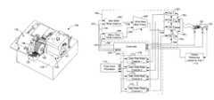
- FIG. 10is a diagrammatic depiction of the media servowriter/certifier apparatus 100 contemplated by the present embodiments.
- An external host 174communicates with a top level controller 176 which, in turn, controls and coordinates activities of the various systems.
- the base 118FIG. 1
- the base 118supports a positioning system such as including the interferometer 114 ( FIG. 2 ) that provides measurements in a closed control loop by which the controller 176 responsively controls the position and movement of the transducers 104 and the rotation of the stack of discs 106 .
- a timing reference 178acquires phase lock with the rotating discs 106 in order to inform the controller 176 of their rotational position.
- the controller 176asserts various read gates and write gates on a communication channel 180 in relation to the timing reference 178 in order to send a write signal simultaneously to each of all of the transducers 104 , and to transduce a read signal simultaneously from each of all the transducers 104 .
- FIG. 11diagrammatically depicts a communication channel 180 constructed in accordance with embodiments of the present invention.
- the top level controller 176controls the operations of a number of components in the communication channel 180 in relation to the timing reference 178 in order to maintain phase coherency amongst the data being stored and retrieved.
- a dedicated preamplifier 182exists for each transducer 104 .
- the controller 176is responsive to the timing reference 178 in asserting a read/write gate on the plurality of preamplifiers 182 via path 184 .
- the controller 176likewise asserts write gates on each of a user data write channel 186 and a servo data write channel 188 via path 190 and path 192 , respectively.
- the timings of the write gates in these channelsare synchronized to the rotation of the discs via write time reference signals provided via paths 194 and 196 , respectively.
- a multiplexer 198receives inputs in the form of a user data stream 200 and a servo data stream 202 from the respective write channels 186 , 188 .
- the multiplexer 198outputs a write signal simultaneously to all of the preamplifiers 182 via path 204 .
- the controller 176For retrieving read signals, the controller 176 asserts read gates on a plurality of dedicated read channels 172 1 , 172 2 , 172 3 , . . . 172 n via path 206 , there being a dedicated read channel 172 associated with each preamplifier 182 .
- each read channel 172preferably matches the characteristic normalization and time domain filtering parameters of the data storage device 100 ′ ( FIG. 7 ) ultimately using the media 106 .
- the read channel 172samples the output of the filtered read signal to provide a sequence of data values representative of the data written to the media 106 .
- the read channel 172also has flaw scan capabilities, whereby the sampled data is compared to predetermined threshold values to indicate the presence of a media flaw, such as shown in the amplitude modulation in FIG. 6 corresponding to the flaw 154 .
- the communication channel 180is capable of simultaneously processing read signals from each of the media.
- the communication channel 180is capable of simultaneously processing read signals from each of the media.
- the controller 176only outputs actual indications of flaws to a flaw scan processor 173 .
- each flaw scan processor 173handles the outputs of four read channels 172 , but the present embodiments are not so limited.
- the flaw scan processor 173makes qualitative judgments of the media 106 based on predetermined metrics, such as in relation to a threshold total number of flaws and/or a number of adjacent “scratches” and the like.
- FIGS. 12 and 13depict two illustrative criteria that can be used to qualitatively judge the media in relation to indicated flaws. Note that the spacing between adjacent tracks 134 in FIGS. 12 and 13 is greatly exaggerated for illustration purposes.
- FIG. 12depicts data tabulated by the flaw scan processor 173 indicating a scratch exists because flaws were detected in seven consecutive tracks 134 and within the same user data wedge 136 .
- the media 106will be judged to be nonconforming and thereby screened out of the production flow if the threshold maximum length for a scratch is set to less than seven data tracks.
- FIG. 13depicts tabulated data indicating that three scratches involving at least one common track 134 were indicated in adjacent user data wedges 136 . Similarly, the media 106 will be judged nonconforming if the threshold maximum number of adjacent overlapping scratches is set to less than three.
- the discussion of servowriting so farhas referenced only the ex-situ media servowriter/certifier apparatus 100 .
- the present embodimentsare not so limited. That is, in equivalent alternative embodiments the servowriting and certifying can be an in-situ process performed on the discs 106 after they have been installed into the disc drive 100 ′ depicted in FIG. 7 . This can be accomplished either by using a servo track writer that positionally controls the actuator 103 ′, or by self servo control schemes.
- the present embodimentscontemplate an apparatus and associated method adapted for either ex-situ or in-situ servowriting and certifying, or a combination of both.
- the disc 106is depicted as being divided into three radial zones A, B, and C.
- the bit density with which data is stored to the data storage device 100 ′is preferably greater at outer tracks, such as in zone C, in comparison to inner tracks, such as in zone A.
- choosing what bit density to use in media certificationcan be problematic. Certifying with a bit density that is different than what the disc drive 100 ′ uses can give a false indication of disc quality with respect to the media's actual performance in the end product.
- FIG. 14diagrammatically depicts how the dual write streams 200 , 202 can vary with respect to a commanded data transfer rate.
- the user and servo write channels 186 , 188are preferably embodied as an integrated circuit in the form of a FPGA or an ASIC. Each channel 186 , 188 receives the timing reference 178 and write gate control via the controller 176 . The channels 186 , 188 also receive commanded data transfer rate(s) from the host 174 .
- the host 174commands the transfer rates to match the characteristic bit densities with which the end product stores data.
- the hostwould command three different transfer rates commensurate with the three zones (A, B, and C) in the data storage device 100 ′ of FIG. 7 .
- Zone transitionsare loaded by the host 174 in terms of servo counts at which to shift the transfer rate.
- each channel 186 , 188has a phase lock loop frequency synthesizer 210 for providing the respective data streams 200 , 202 at a desired transfer rate.
- a pattern generator 221such as embodied as a finite state machine, loads bit patterns to a pattern buffer 223 . The bit patterns are then serialized and interleaved by the multiplexer 198 to provide the write signal 204 to all the preamplifiers 182 simultaneously.
- FIG. 15diagrammatically depicts the read channel 172 being provided as an integrated circuit on a daughter card 230 that is swappable on the control board 108 ( FIG. 2 ).
- FIG. 16depicts a portion of four adjacent data tracks 134 1 , 134 2 , 134 3 , 134 4 repeatedly used in the FIGS. that follow as the disc 106 makes sequential passes, or revolutions, with respect to the transducer 104 .
- the disc 106 in these FIGS.is rotating counter-clockwise.
- the transducer 104indexes to the next data track 134 in a downward direction after storing a full compliment of servo data to a particular data track 134 .
- the transducer 104has a write element 240 and a read element 242 that are offset from each other in the cross track direction. Preferably, the offset is on the order of about twenty data tracks 134 .
- the much smaller offset in FIGS. 16-23is solely diagrammatic in nature for the purpose of simplifying the illustrations for clarity sake. These illustrative FIGS. in no way define or limit the contemplated embodiments to the offset depicted.
- the effective width of the write element 240is depicted as being one and one-half data tracks wide, and the read element 242 is depicted as being about three-quarters of the data track width. These sizes, too, are illustrative and not limiting of the present embodiments, although preferably the write element 240 is wider than the data tracks 134 and the read element 242 is narrower than the data tracks 134 .
- the trailing edge (with respect to cross track direction) of the write element 240is aligned with a servo burst seam 244 that lies between the dibit patterns of the POS field 146 ( FIG. 5 ) portion of the servo data.
- the opposing boundaries of the data track 134 1 and the servo burst seam 244define servo data tracks 246 , 248 within data track 134 1 .
- FIG. 17shows the transducer 104 having traversed this portion of the disc 106 during a first pass (revolution) of the disc 106 .
- the write element 240stores servo bursts of a first polarity (“A bursts”) A 1 , A 2 , A 3 within each of the respective servo wedges 130 ( FIG. 5 ) in track 134 1 . It is understood that the write element 240 also writes the rest of the servo data ( FIG.
- a predetermined user data patternsuch as the oscillating 2T pattern depicted as 2T 2
- FIG. 18depicts the transducer 104 having indexed one servo track in the cross track direction and there traversed this portion of the disc 106 during a second pass.
- Servo bursts of an opposite polarity(“B bursts”) are written to each of the servo wedges 130 , trimming the previously written A bursts to align the AB seam at the boundary between data track 134 1 and data track 134 2 .
- the 2T datais also written in the user data wedges 136 , but in an opposite pattern to the pattern in the first pass. That is, during this second pass the 2T pattern is stored between B 1 &B 2 , between B 3 &B 4 , between B 5 &B 6 , . . . and between B (2n ⁇ 1) &B 2n .
- FIG. 19depicts the transducer 104 having indexed another servo track in the cross track direction and there traversed this portion of the disc 106 during a third pass.
- the write element 240repeats the pattern previously stored during the first pass in FIG. 17 , storing servo bursts A 1 , A 2 , A 3 . . . An and storing the 2T pattern between A 2 &A 3 . . . A 2n &A 2n+1 .
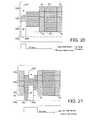
- FIG. 20depicts the transducer 104 having indexed another servo track in the cross track direction and there disposed at the first of the three servo wedges 130 during a fourth pass of the disc 106 .
- the controller 176( FIGS. 10 & 11 ) asserts a write gate on the servo write channel 188 to produce a servo data stream through the multiplexer 198 and to each of the write elements 240 to store the B 1 servo burst.
- the disc 106has rotated during the fourth pass to where the transducer 104 is disposed at the first of the two user data wedges 136 .
- the controller 176now asserts a write gate on the user data write channel 186 to produce the 2T pattern through the multiplexer 198 and to each of the write elements 240 to store the 2T 1 pattern.
- the disc 106has rotated further during the fourth pass to where the transducer 104 is disposed at the second of the three servo wedges 130 .
- the controller 176asserts a write gate on the servo write channel 188 to produce a servo data stream through the multiplexer 198 and to each of the write elements 240 to store the B 2 servo burst.
- the disc 106has rotated further during the fourth pass to where the transducer 104 is disposed at the second user data wedge 136 .
- the controller 176asserts a read gate on each of the read channels 172 to transduce a read signal from the previously stored 2T 2 data.
- the read channels 172filter and sample the respective read signals for indications of media flaws.
- the flaw scan controller 171records the indications of flaws and the flaw scan processor 173 makes qualitative decisions about the discs 106 with respect to the number or the number and location of the indicated flaws.
- FIG. 11depicts how the servowriter/certifier apparatus 100 uses the timing reference 178 to acquire phase lock with the moving storage media 106 .
- the controller 176executes programming instructions stored in memory 250 that are responsive to the timing reference 178 in interleaving the servo data stream 202 and the user data stream 200 to form the write signal 204 .
- the write signal 204is communicated to all of the preamplifiers 182 simultaneously.
- the write signal 204stores a full compliment of position servo bursts to the media 106 for a given servo track during only one complete pass of the media.
- full complimentit is meant that position servo bursts are stored to all servo wedges 130 ( FIG.
- the controller 176In addition to asserting write gates to store all A bursts to a first servo track during a first pass and to store all B bursts to a second servo track during a second pass, the controller 176 also asserts a read gate to retrieve read data from all user data wedges of a data track during the same time that the A bursts and B bursts are stored to the first and second servo tracks.
- the write element 240is periodically storing the B servo bursts. Also, during a first pass of the disc 106 the write element 240 stores the 2T pattern after the B 1 servo burst, and subsequently in FIG. 23 the read element 242 transduces a read signal from the previously stored 2T data after the B 2 servo burst.
- the transducer 104next indexes to align the write element 240 with the servo sector seam at the centerline of the next data track 134 3 .
- the write element 240stores the A servo bursts and again alternates between reading user data with the read element 242 and storing user data with the write element 240 after each servo burst.
- the pattern of alternating between storing user data and retrieving user data during the second passis opposite to that performed during the first pass, regardless of the pattern during the first pass, so that ultimately user data is stored to all user data wedges in the first radial position (write element 240 position) and read signals are transduced from all user data wedges in the second radial position (read element 242 position).
- the interleaving the servo data stream and the user data streamcan be by either entirely storing user data at the first radial position or entirely retrieving the previously stored user data from all user data wedges during the first pass of the disc 106 .
- the opposite processis performed, so that ultimately user data is stored to all user data wedges in the first radial position (write element 240 position) and read signals are transduced from all user data wedges in the second radial position (read element 242 position).
- the media servowriter/certifier apparatus 100advantageously employs a communication circuit 156 ( FIG. 8 ) having a read channel 172 that matches read channel parameters of a data storage device 100 ′ ( FIG. 7 ) ultimately using the media 106 .
- the read channel 172can be provided on the daughter card 230 ( FIG. 15 ) that is swappable on the control board 108 , or in alternative equivalent embodiments the read channel 172 can be configurable by executing software/firmware routines.
- the read channel 172is capable of sampling the read signal from the transducer 104 and comparing sampling values to predetermined threshold values 181 ( FIG. 6 ) that associate characteristics of the read signal with a presence of a flaw in the media.
- the location of an indicated flawcan be recorded in terms of the servo data that was stored immediately preceding the indication of the flaw.
- the present embodimentsare adaptable to processing a plurality of discs 106 simultaneously.
- the storing servo data steps and the storing user data steps by the write element 240are performed by sending a write signal to each of the dedicated preamplifiers 182 ( FIG. 11 ) simultaneously.
- Each preamplifier 182is part of a dedicated read channel 172 for processing each of the plurality of read signals simultaneously.
- the present embodimentspermit using the media servowriter/certifier apparatus 100 to concurrently store servo data and user data to and retrieve user data from a media that is destined for use in a particular first product.
- the media servowriter/certifier 100can then be reconfigured in order to concurrently store servo data and user data to and retrieve user data from another media that is destined for use in a particular second product that is characteristically different than the first product.
- the disclosed embodimentscontemplate a media servowriter/certifier having a plurality of data transfer members disposed in a data transfer relationship with a respective plurality of data storage media, and means for certifying while servowriting by interleaving streams of servo data and user data and storing the interleaved stream at a first location of each of the plurality of media, while retrieving previously stored user data from a second location of each of the plurality of media, wherein a full compliment of the user data is retrieved from the second location within a timeframe during which a full compliment of the servo data is stored to the first location in a minimum possible number of passes between the plurality of storage media and the plurality of data transfer members.
- the term “means for certifying while servowriting”includes the disclosed structure and structural equivalents thereof that are capable or interleaving servo data and user data in order to write a full compliment of servo data in a minimum possible number of passes while simultaneously performing a 100% media certification.
- 100% certificationit is meant that read data from each of the user data wedges is processed to determine whether flaws exist.
- the minimum number of passesis two for writing an AB servo pattern to all the servo wedges of a track, so the 100% media certification is accordingly performed within two passes for each track in that case in accordance with the claimed embodiments.
- the term “means for certifying while servowriting”expressly does not include previously attempted solutions that either require more than the minimum possible number of passes to write the full compliment of servo data or that perform less than a 100% media certification. Also as set forth above, “interleaving” the servo data and user data can mean that user data is written to all user data wedges during one pass and that read data is retrieved from all user data wedges in another pass, or it can mean that the user data is stored to some of the user data wedges and read data is retrieved from other of the user data wedges during each of both passes.
Landscapes
- Engineering & Computer Science (AREA)
- Signal Processing (AREA)
- Signal Processing For Digital Recording And Reproducing (AREA)
Abstract
Description
Claims (24)
Priority Applications (1)
| Application Number | Priority Date | Filing Date | Title |
|---|---|---|---|
| US12/016,175US7880987B2 (en) | 2007-03-30 | 2008-01-17 | Media servowriter/certifier |
Applications Claiming Priority (6)
| Application Number | Priority Date | Filing Date | Title |
|---|---|---|---|
| US92114807P | 2007-03-30 | 2007-03-30 | |
| US92114707P | 2007-03-30 | 2007-03-30 | |
| US92123507P | 2007-03-30 | 2007-03-30 | |
| US92123407P | 2007-03-30 | 2007-03-30 | |
| US92123307P | 2007-03-30 | 2007-03-30 | |
| US12/016,175US7880987B2 (en) | 2007-03-30 | 2008-01-17 | Media servowriter/certifier |
Publications (2)
| Publication Number | Publication Date |
|---|---|
| US20080239540A1 US20080239540A1 (en) | 2008-10-02 |
| US7880987B2true US7880987B2 (en) | 2011-02-01 |
Family
ID=39793856
Family Applications (2)
| Application Number | Title | Priority Date | Filing Date |
|---|---|---|---|
| US12/016,175Expired - Fee RelatedUS7880987B2 (en) | 2007-03-30 | 2008-01-17 | Media servowriter/certifier |
| US12/016,169Expired - Fee RelatedUS7768736B2 (en) | 2007-03-30 | 2008-01-17 | Certifying while servowriting media |
Family Applications After (1)
| Application Number | Title | Priority Date | Filing Date |
|---|---|---|---|
| US12/016,169Expired - Fee RelatedUS7768736B2 (en) | 2007-03-30 | 2008-01-17 | Certifying while servowriting media |
Country Status (1)
| Country | Link |
|---|---|
| US (2) | US7880987B2 (en) |
Cited By (3)
| Publication number | Priority date | Publication date | Assignee | Title |
|---|---|---|---|---|
| US9236074B1 (en) | 2015-01-26 | 2016-01-12 | Seagate Technology Llc | Multi-disk writer with individual head positioning |
| US20160284369A1 (en)* | 2015-03-25 | 2016-09-29 | Guzik Technical Enterprises | Head gimbal assembly (hga) support cartridge for magnetic head and disk testers |
| US11762731B2 (en) | 2021-11-12 | 2023-09-19 | Seagate Technology Llc | Codeword redundancy |
Families Citing this family (9)
| Publication number | Priority date | Publication date | Assignee | Title |
|---|---|---|---|---|
| US9472223B1 (en) | 2015-09-09 | 2016-10-18 | Seagate Technology Llc | Media certification with different recording widths |
| US10210899B1 (en) | 2018-05-21 | 2019-02-19 | Seagate Technology Llc | Skip track flaw scan methods and systems |
| US10290319B1 (en) | 2018-08-08 | 2019-05-14 | Seagate Technology Llc | High rpm hard disk drive testing |
| TWI786519B (en) | 2020-01-29 | 2022-12-11 | 美商艾德凡斯化學公司 | Amino acid surfactants |
| TWI856233B (en) | 2020-01-29 | 2024-09-21 | 美商艾德凡斯化學公司 | Amino acid surfactants |
| CN115461436A (en) | 2020-03-11 | 2022-12-09 | 艾德凡斯化学公司 | Surfactants for Cleaning Products |
| JP2023517664A (en) | 2020-03-11 | 2023-04-26 | アドバンシックス・レジンズ・アンド・ケミカルズ・リミテッド・ライアビリティ・カンパニー | Surfactants for oil and gas production |
| US11992008B2 (en) | 2020-03-11 | 2024-05-28 | Advansix Resins & Chemicals Llc | Surfactants for agricultural products |
| IL296236A (en) | 2020-03-11 | 2022-11-01 | Advansix Resins & Chemicals Llc | Surfactants for inks, paints and adhesives |
Citations (57)
| Publication number | Priority date | Publication date | Assignee | Title |
|---|---|---|---|---|
| US4656420A (en)* | 1982-10-14 | 1987-04-07 | Basf Aktiengesellschaft | Method and circuit arrangements for detecting and evaluating faults in recording media having digital signals recorded on one or more tracks |
| US5047874A (en)* | 1989-03-31 | 1991-09-10 | Unisys Corp. | Technique for certifying disk recording surface |
| US5050169A (en)* | 1989-05-23 | 1991-09-17 | Memory Technology | Method and apparatus for testing magnetic disks |
| US5075804A (en)* | 1989-03-31 | 1991-12-24 | Alps Electric Co., Ltd. | Management of defect areas in recording media |
| US5247254A (en) | 1990-12-21 | 1993-09-21 | Maxtor Corporation | Data recording system incorporating flaw detection circuitry |
| US5375020A (en)* | 1990-09-26 | 1994-12-20 | Digital Equipment Corporation | Method and apparatus for writing or reading servo information |
| US5423111A (en) | 1992-09-22 | 1995-06-13 | Hitachi Electronics Engineering Co., Ltd. | Magnetic disk tester |
| US5423524A (en) | 1993-08-17 | 1995-06-13 | Techmetric Machine Works, Inc. | Low-profile quick-release clamp |
| US5563746A (en) | 1994-11-17 | 1996-10-08 | Cirrus Logic, Inc. | Real time media defect scanning in a sampled amplitude read channel |
| US5682274A (en) | 1990-10-02 | 1997-10-28 | International Business Machines Corporation | Method and apparatus for positioning transducers to correct for read and write element misregistration offsets which vary dependent on rotary actuator angular position across a disk medium |
| US5812560A (en) | 1996-07-19 | 1998-09-22 | Hitachi Electronics Engineering Co., Ltd. | Magnetic disk certifier |
| US5935261A (en)* | 1997-06-05 | 1999-08-10 | International Business Machines Corporation | Method and apparatus for detecting handling damage in a disk drive |
| US6061200A (en) | 1996-02-27 | 2000-05-09 | Quantum Corporation | In-drive correction of servo pattern errors |
| US6084738A (en) | 1997-08-15 | 2000-07-04 | Seagate Technology, Inc. | Writing servo information to a disc drive at a constant density |
| US6098140A (en) | 1998-06-11 | 2000-08-01 | Adaptec, Inc. | Modular bus bridge system compatible with multiple bus pin configurations |
| US6118604A (en) | 1997-08-15 | 2000-09-12 | Seagate Technology, Inc. | Constant density servo information in a disc drive |
| US6154858A (en)* | 1998-04-17 | 2000-11-28 | International Business Machines Corporation | In situ method and apparatus for detecting surface defects to identify handling damage in a disk drive |
| US6204660B1 (en)* | 1997-06-03 | 2001-03-20 | Samsung Electronics Co., Ltd. | Method of varying capacity of head disk drive during manufacturing process by checking head/disk combinations for defects |
| US6262857B1 (en) | 1997-03-11 | 2001-07-17 | Western Digital Corporation | Disk drive including a recording surface employing servo zones with banded data zones |
| US6292317B1 (en)* | 1999-09-02 | 2001-09-18 | Maxtor Corporation | Method and apparatus for performing a flaw scan of a disk drive |
| US6330122B1 (en) | 1999-05-24 | 2001-12-11 | International Business Machines Corporation | Magnetic tester for disk surface scan |
| US6353315B1 (en)* | 1999-08-27 | 2002-03-05 | Maxtor Corporation | Method and apparatus for using the data interface of a disk drive to identify and characterize disk flaws |
| US20030002190A1 (en) | 2001-06-29 | 2003-01-02 | Teo Song Wee | Disk drive with optimized read gate delay |
| US6552535B2 (en) | 2000-09-28 | 2003-04-22 | Hitachi Electronics Engineering Co., Ltd. | Defect detector circuit with a signal synthesizer and magnet disk certifier using the same defect detector circuit |
| US6560052B2 (en) | 1998-07-13 | 2003-05-06 | Seagate Technology Llc | Implementation of variable bit density recording in storage disc drives |
| US6587293B1 (en) | 1999-05-07 | 2003-07-01 | Seagate Technology Llc | Method for servo writing servo pattern at a desired speed |
| US20030123172A1 (en) | 2001-11-30 | 2003-07-03 | Jun Zhu | System and method for efficient media certification during servowriting |
| US20030182070A1 (en) | 2002-03-20 | 2003-09-25 | Jun Zhu | New defect detection technique for media certification |
| US6724558B2 (en) | 2000-04-19 | 2004-04-20 | Jpmorgan Chase Bank | Servo writing in a disc drive with substantially identical heads having read and write elements in a radial offset position |
| US20040100719A1 (en) | 2002-11-22 | 2004-05-27 | Seagate Technology Llc | Writing multiple servo sector patterns to improve servo sector alignment on multiple surfaces |
| US6765744B2 (en) | 2001-03-30 | 2004-07-20 | Kevin Arthur Gomez | Track pitch control using head offset measurement for self-servowriting tracks in a disc drive |
| US20040145825A1 (en) | 2003-01-24 | 2004-07-29 | Xyratex Technology Limited | Methods and apparatus for writing servo frames to and/or verifying data areas of a storage medium |
| US6888154B2 (en) | 2001-10-18 | 2005-05-03 | Seagate Technology Llc | Method of marking and detecting disc index |
| US6906883B2 (en) | 2000-09-14 | 2005-06-14 | Samsung Electronics Ltd., Co. | Servo defect management scheme in hard disk drives |
| US6909568B2 (en) | 1998-11-30 | 2005-06-21 | Fujitsu Limited | Servo data writing device |
| US6934112B2 (en) | 2003-03-04 | 2005-08-23 | Fuji Electric Device Technology Co. Ltd. | Method for obtaining head positions in magnetic data writing apparatus |
| US20050195727A1 (en) | 2004-03-03 | 2005-09-08 | Seagate Technology Llc | Optical detection of a light scattering target |
| US6947232B2 (en) | 2001-04-26 | 2005-09-20 | Seagate Technology Llc | User data wedge media certification apparatus and method |
| US6958874B1 (en) | 1999-09-20 | 2005-10-25 | Westwind Air Bearings Ltd. | Manufacture of data storage device |
| US20050244167A1 (en) | 2004-04-29 | 2005-11-03 | Liew Sanyuan | Signal-to-noise ratio (SNR) value characterization in a data recovery channel |
| US6967807B2 (en) | 2003-08-18 | 2005-11-22 | Seagate Technology Llc | Selecting physical cylinders in a disc drive employing discs with pre-written servo patterns |
| US20050265504A1 (en) | 2004-05-27 | 2005-12-01 | Xyratex Technology Limited | Clock recovery circuit and a method of generating a recovered clock signal |
| US20050265487A1 (en) | 2004-05-27 | 2005-12-01 | Xyratex Technology Limited | Method of sampling data and a circuit for sampling data |
| US6977791B2 (en) | 2002-03-23 | 2005-12-20 | Kla-Tencor Technologies Corporation | Media servowriting system |
| US7012773B2 (en) | 2002-04-18 | 2006-03-14 | Fujitsu Limited | Disk device and disk medium, in which a plurality of servo cylinders formed concentrically from the inner diametrical portion to the outer diametrical portion of at least one disk are divided into predetermined areas |
| US7032127B1 (en) | 2000-05-09 | 2006-04-18 | Maxtor Corporation | Method and apparatus for identifying defective areas on a disk surface of a disk drive based on defect density |
| US20060187907A1 (en) | 2003-03-03 | 2006-08-24 | Xyratex Technology Limited | Apparatus and method for switching data packets |
| US20060221488A1 (en) | 2005-04-01 | 2006-10-05 | Riospring, Inc. | Multi-disk simultaneous servo writing device |
| US7133228B2 (en) | 2003-10-10 | 2006-11-07 | Seagate Technology Llc | Using data compression to achieve lower linear bit densities on a storage medium |
| US20060268939A1 (en) | 2003-08-15 | 2006-11-30 | Xyratex Technology Limited | Data merge unit , a method of producing an interleaved data stream, a network analyser and a method of analysing a network |
| US20070008643A1 (en) | 2005-07-05 | 2007-01-11 | Xyratex Technology Limited | Methods and apparatus for generating a clock signal, for writing servo tracks, and for characterising timing errors in a servo track writer |
| US7170703B1 (en) | 2000-05-09 | 2007-01-30 | Maxtor Corporation | Flaw detection in disk drive using significant samples of data pattern stored on disk |
| US7173785B2 (en) | 2002-06-25 | 2007-02-06 | Hitachi Global Storage Technologies Netherlands B.V. | Data storage device and servo information writing method |
| US7187148B2 (en) | 2004-11-26 | 2007-03-06 | Fanuc Ltd | Controller |
| US20070064325A1 (en) | 2005-09-21 | 2007-03-22 | Seagate Technology Llc | Data storage medium with optimized servo format |
| US7293226B2 (en) | 2002-11-25 | 2007-11-06 | Samsung Electronics Co., Ltd. | Method and apparatus for adaptively performing defect scan according to channel characteristics |
| US7349172B2 (en) | 2006-08-18 | 2008-03-25 | Seagate Technology Llc | Certifying concentric data in eccentric servo data tracks of pre-formatted media |
Family Cites Families (5)
| Publication number | Priority date | Publication date | Assignee | Title |
|---|---|---|---|---|
| US5333140A (en)* | 1991-10-03 | 1994-07-26 | Helios Incorporated | Servowriter/certifier |
| KR100214308B1 (en)* | 1996-05-11 | 1999-08-02 | 윤종용 | Hard disk drive test device |
| KR100223632B1 (en)* | 1996-10-30 | 1999-10-15 | 윤종용 | Automated system for improving yield of test process of head disk assembly and its operation method |
| US6738205B1 (en)* | 2001-07-08 | 2004-05-18 | Maxtor Corporation | Self-writing of servo patterns in disk drives |
| US7035039B2 (en)* | 2002-01-08 | 2006-04-25 | Hitachi Electronics Engineering Co., Ltd. | Magnetic head positioning control device, magnetic head certifier, magnetic disk certifier and head cartridge |
- 2008
- 2008-01-17USUS12/016,175patent/US7880987B2/ennot_activeExpired - Fee Related
- 2008-01-17USUS12/016,169patent/US7768736B2/ennot_activeExpired - Fee Related
Patent Citations (59)
| Publication number | Priority date | Publication date | Assignee | Title |
|---|---|---|---|---|
| US4656420A (en)* | 1982-10-14 | 1987-04-07 | Basf Aktiengesellschaft | Method and circuit arrangements for detecting and evaluating faults in recording media having digital signals recorded on one or more tracks |
| US5047874A (en)* | 1989-03-31 | 1991-09-10 | Unisys Corp. | Technique for certifying disk recording surface |
| US5075804A (en)* | 1989-03-31 | 1991-12-24 | Alps Electric Co., Ltd. | Management of defect areas in recording media |
| US5050169A (en)* | 1989-05-23 | 1991-09-17 | Memory Technology | Method and apparatus for testing magnetic disks |
| US5375020A (en)* | 1990-09-26 | 1994-12-20 | Digital Equipment Corporation | Method and apparatus for writing or reading servo information |
| US5682274A (en) | 1990-10-02 | 1997-10-28 | International Business Machines Corporation | Method and apparatus for positioning transducers to correct for read and write element misregistration offsets which vary dependent on rotary actuator angular position across a disk medium |
| US5247254A (en) | 1990-12-21 | 1993-09-21 | Maxtor Corporation | Data recording system incorporating flaw detection circuitry |
| US5423111A (en) | 1992-09-22 | 1995-06-13 | Hitachi Electronics Engineering Co., Ltd. | Magnetic disk tester |
| US5423524A (en) | 1993-08-17 | 1995-06-13 | Techmetric Machine Works, Inc. | Low-profile quick-release clamp |
| US5563746A (en) | 1994-11-17 | 1996-10-08 | Cirrus Logic, Inc. | Real time media defect scanning in a sampled amplitude read channel |
| US6061200A (en) | 1996-02-27 | 2000-05-09 | Quantum Corporation | In-drive correction of servo pattern errors |
| US5812560A (en) | 1996-07-19 | 1998-09-22 | Hitachi Electronics Engineering Co., Ltd. | Magnetic disk certifier |
| US6441981B1 (en) | 1997-03-11 | 2002-08-27 | Western Digital Technologies, Inc. | Disk drive including a recording surface employing servo zones recorded at a channel frequency different from data zones |
| US6262857B1 (en) | 1997-03-11 | 2001-07-17 | Western Digital Corporation | Disk drive including a recording surface employing servo zones with banded data zones |
| US6204660B1 (en)* | 1997-06-03 | 2001-03-20 | Samsung Electronics Co., Ltd. | Method of varying capacity of head disk drive during manufacturing process by checking head/disk combinations for defects |
| US5935261A (en)* | 1997-06-05 | 1999-08-10 | International Business Machines Corporation | Method and apparatus for detecting handling damage in a disk drive |
| US6084738A (en) | 1997-08-15 | 2000-07-04 | Seagate Technology, Inc. | Writing servo information to a disc drive at a constant density |
| US6118604A (en) | 1997-08-15 | 2000-09-12 | Seagate Technology, Inc. | Constant density servo information in a disc drive |
| US6154858A (en)* | 1998-04-17 | 2000-11-28 | International Business Machines Corporation | In situ method and apparatus for detecting surface defects to identify handling damage in a disk drive |
| US6098140A (en) | 1998-06-11 | 2000-08-01 | Adaptec, Inc. | Modular bus bridge system compatible with multiple bus pin configurations |
| US6560052B2 (en) | 1998-07-13 | 2003-05-06 | Seagate Technology Llc | Implementation of variable bit density recording in storage disc drives |
| US6909568B2 (en) | 1998-11-30 | 2005-06-21 | Fujitsu Limited | Servo data writing device |
| US6587293B1 (en) | 1999-05-07 | 2003-07-01 | Seagate Technology Llc | Method for servo writing servo pattern at a desired speed |
| US6330122B1 (en) | 1999-05-24 | 2001-12-11 | International Business Machines Corporation | Magnetic tester for disk surface scan |
| US6353315B1 (en)* | 1999-08-27 | 2002-03-05 | Maxtor Corporation | Method and apparatus for using the data interface of a disk drive to identify and characterize disk flaws |
| US6292317B1 (en)* | 1999-09-02 | 2001-09-18 | Maxtor Corporation | Method and apparatus for performing a flaw scan of a disk drive |
| US6958874B1 (en) | 1999-09-20 | 2005-10-25 | Westwind Air Bearings Ltd. | Manufacture of data storage device |
| US6724558B2 (en) | 2000-04-19 | 2004-04-20 | Jpmorgan Chase Bank | Servo writing in a disc drive with substantially identical heads having read and write elements in a radial offset position |
| US7170703B1 (en) | 2000-05-09 | 2007-01-30 | Maxtor Corporation | Flaw detection in disk drive using significant samples of data pattern stored on disk |
| US7032127B1 (en) | 2000-05-09 | 2006-04-18 | Maxtor Corporation | Method and apparatus for identifying defective areas on a disk surface of a disk drive based on defect density |
| US6906883B2 (en) | 2000-09-14 | 2005-06-14 | Samsung Electronics Ltd., Co. | Servo defect management scheme in hard disk drives |
| US6552535B2 (en) | 2000-09-28 | 2003-04-22 | Hitachi Electronics Engineering Co., Ltd. | Defect detector circuit with a signal synthesizer and magnet disk certifier using the same defect detector circuit |
| US6765744B2 (en) | 2001-03-30 | 2004-07-20 | Kevin Arthur Gomez | Track pitch control using head offset measurement for self-servowriting tracks in a disc drive |
| US6947232B2 (en) | 2001-04-26 | 2005-09-20 | Seagate Technology Llc | User data wedge media certification apparatus and method |
| US20030002190A1 (en) | 2001-06-29 | 2003-01-02 | Teo Song Wee | Disk drive with optimized read gate delay |
| US6888154B2 (en) | 2001-10-18 | 2005-05-03 | Seagate Technology Llc | Method of marking and detecting disc index |
| US20030123172A1 (en) | 2001-11-30 | 2003-07-03 | Jun Zhu | System and method for efficient media certification during servowriting |
| US20030182070A1 (en) | 2002-03-20 | 2003-09-25 | Jun Zhu | New defect detection technique for media certification |
| US20060119977A1 (en) | 2002-03-23 | 2006-06-08 | Jun Zhu | Media servowriting system |
| US6977791B2 (en) | 2002-03-23 | 2005-12-20 | Kla-Tencor Technologies Corporation | Media servowriting system |
| US7012773B2 (en) | 2002-04-18 | 2006-03-14 | Fujitsu Limited | Disk device and disk medium, in which a plurality of servo cylinders formed concentrically from the inner diametrical portion to the outer diametrical portion of at least one disk are divided into predetermined areas |
| US7173785B2 (en) | 2002-06-25 | 2007-02-06 | Hitachi Global Storage Technologies Netherlands B.V. | Data storage device and servo information writing method |
| US20040100719A1 (en) | 2002-11-22 | 2004-05-27 | Seagate Technology Llc | Writing multiple servo sector patterns to improve servo sector alignment on multiple surfaces |
| US7293226B2 (en) | 2002-11-25 | 2007-11-06 | Samsung Electronics Co., Ltd. | Method and apparatus for adaptively performing defect scan according to channel characteristics |
| US20040145825A1 (en) | 2003-01-24 | 2004-07-29 | Xyratex Technology Limited | Methods and apparatus for writing servo frames to and/or verifying data areas of a storage medium |
| US20060187907A1 (en) | 2003-03-03 | 2006-08-24 | Xyratex Technology Limited | Apparatus and method for switching data packets |
| US6934112B2 (en) | 2003-03-04 | 2005-08-23 | Fuji Electric Device Technology Co. Ltd. | Method for obtaining head positions in magnetic data writing apparatus |
| US20060268939A1 (en) | 2003-08-15 | 2006-11-30 | Xyratex Technology Limited | Data merge unit , a method of producing an interleaved data stream, a network analyser and a method of analysing a network |
| US6967807B2 (en) | 2003-08-18 | 2005-11-22 | Seagate Technology Llc | Selecting physical cylinders in a disc drive employing discs with pre-written servo patterns |
| US7133228B2 (en) | 2003-10-10 | 2006-11-07 | Seagate Technology Llc | Using data compression to achieve lower linear bit densities on a storage medium |
| US20050195727A1 (en) | 2004-03-03 | 2005-09-08 | Seagate Technology Llc | Optical detection of a light scattering target |
| US20050244167A1 (en) | 2004-04-29 | 2005-11-03 | Liew Sanyuan | Signal-to-noise ratio (SNR) value characterization in a data recovery channel |
| US20050265504A1 (en) | 2004-05-27 | 2005-12-01 | Xyratex Technology Limited | Clock recovery circuit and a method of generating a recovered clock signal |
| US20050265487A1 (en) | 2004-05-27 | 2005-12-01 | Xyratex Technology Limited | Method of sampling data and a circuit for sampling data |
| US7187148B2 (en) | 2004-11-26 | 2007-03-06 | Fanuc Ltd | Controller |
| US20060221488A1 (en) | 2005-04-01 | 2006-10-05 | Riospring, Inc. | Multi-disk simultaneous servo writing device |
| US20070008643A1 (en) | 2005-07-05 | 2007-01-11 | Xyratex Technology Limited | Methods and apparatus for generating a clock signal, for writing servo tracks, and for characterising timing errors in a servo track writer |
| US20070064325A1 (en) | 2005-09-21 | 2007-03-22 | Seagate Technology Llc | Data storage medium with optimized servo format |
| US7349172B2 (en) | 2006-08-18 | 2008-03-25 | Seagate Technology Llc | Certifying concentric data in eccentric servo data tracks of pre-formatted media |
Cited By (4)
| Publication number | Priority date | Publication date | Assignee | Title |
|---|---|---|---|---|
| US9236074B1 (en) | 2015-01-26 | 2016-01-12 | Seagate Technology Llc | Multi-disk writer with individual head positioning |
| US20160284369A1 (en)* | 2015-03-25 | 2016-09-29 | Guzik Technical Enterprises | Head gimbal assembly (hga) support cartridge for magnetic head and disk testers |
| US10115420B2 (en)* | 2015-03-25 | 2018-10-30 | Guzik Technical Enterprises | Head gimbal assembly (HGA) support cartridge for magnetic head and disk testers |
| US11762731B2 (en) | 2021-11-12 | 2023-09-19 | Seagate Technology Llc | Codeword redundancy |
Also Published As
| Publication number | Publication date |
|---|---|
| US7768736B2 (en) | 2010-08-03 |
| US20080239540A1 (en) | 2008-10-02 |
| US20080239535A1 (en) | 2008-10-02 |
Similar Documents
| Publication | Publication Date | Title |
|---|---|---|
| US7880987B2 (en) | Media servowriter/certifier | |
| US6078453A (en) | Method and apparatus for optimizing the servo read channel of a hard disk drive | |
| US6421197B1 (en) | Optimal reader/writer offsets and write fault thresholds in a disc drive | |
| US6731442B2 (en) | Method and apparatus for detecting media defects | |
| US7369340B1 (en) | Disk drive detecting disk warping by detecting negative correlation between read signal amplitudes from top and bottom disk surfaces | |
| US6657803B1 (en) | Method and apparatus for data error recovery using defect threshold detector and viterbi gain | |
| US6178056B1 (en) | Disk drive employing state variable trap registers for providing stored servo and user data state variables to sampled-data channel | |
| EP1596390B1 (en) | Data recording system | |
| US20070279788A1 (en) | Method and apparatus to perform defect scanning | |
| US6873488B2 (en) | Enhanced MR offset with dynamic tuning range | |
| US6678110B2 (en) | Robust servo demodulation filtering method | |
| US6226140B1 (en) | Shock detector in a disk drive servo control system | |
| US6947232B2 (en) | User data wedge media certification apparatus and method | |
| US6078445A (en) | Gain control for a dual burst, dual frequency PES servo pattern | |
| JP2001229637A (en) | Magnetic head floating amount abnormality detection method, data write method and hard disk drive device | |
| US6839193B2 (en) | Method and apparatus for determining read-to-write head offset of a disk drive | |
| JP2003524854A (en) | Accumulate read channel performance data | |
| US6665134B2 (en) | Methods and apparatus for detection and analysis of an envelope of a frequency modulated readback signal in a magnetic storage system | |
| US9019638B1 (en) | Systems and methods for performing timing acquisition in a read/write channel module | |
| US8570679B2 (en) | Read channel averaging | |
| US8300349B2 (en) | Systems and methods for format efficient calibration for servo data based harmonics calculation | |
| US6285522B1 (en) | Rotational vibration compensation using a dedicated surface with a constant frequency pattern | |
| US20040252398A1 (en) | Method and apparatus for tuning a magnetoresistive bias parameter in a data storage system | |
| US6002541A (en) | Method and apparatus for providing a linear position error sensing (PES) signal | |
| US20020075585A1 (en) | Automated drive-level microtrack profile using variable gain amplifier |
Legal Events
| Date | Code | Title | Description |
|---|---|---|---|
| AS | Assignment | Owner name:SEAGATE TECHNOLOGY LLC, CALIFORNIA Free format text:ASSIGNMENT OF ASSIGNORS INTEREST;ASSIGNORS:BELMONT, KEN L.;MCLERAN, DAN R.;WILLIAMSON, DAVE SCOTT;AND OTHERS;REEL/FRAME:020382/0560;SIGNING DATES FROM 20070920 TO 20080116 Owner name:SEAGATE TECHNOLOGY LLC, CALIFORNIA Free format text:ASSIGNMENT OF ASSIGNORS INTEREST;ASSIGNORS:BELMONT, KEN L.;MCLERAN, DAN R.;WILLIAMSON, DAVE SCOTT;AND OTHERS;SIGNING DATES FROM 20070920 TO 20080116;REEL/FRAME:020382/0560 | |
| AS | Assignment | Owner name:WELLS FARGO BANK, NATIONAL ASSOCIATION, AS COLLATERAL AGENT AND SECOND PRIORITY REPRESENTATIVE, CALIFORNIA Free format text:SECURITY AGREEMENT;ASSIGNORS:MAXTOR CORPORATION;SEAGATE TECHNOLOGY LLC;SEAGATE TECHNOLOGY INTERNATIONAL;REEL/FRAME:022757/0017 Effective date:20090507 Owner name:JPMORGAN CHASE BANK, N.A., AS ADMINISTRATIVE AGENT AND FIRST PRIORITY REPRESENTATIVE, NEW YORK Free format text:SECURITY AGREEMENT;ASSIGNORS:MAXTOR CORPORATION;SEAGATE TECHNOLOGY LLC;SEAGATE TECHNOLOGY INTERNATIONAL;REEL/FRAME:022757/0017 Effective date:20090507 Owner name:JPMORGAN CHASE BANK, N.A., AS ADMINISTRATIVE AGENT Free format text:SECURITY AGREEMENT;ASSIGNORS:MAXTOR CORPORATION;SEAGATE TECHNOLOGY LLC;SEAGATE TECHNOLOGY INTERNATIONAL;REEL/FRAME:022757/0017 Effective date:20090507 Owner name:WELLS FARGO BANK, NATIONAL ASSOCIATION, AS COLLATE Free format text:SECURITY AGREEMENT;ASSIGNORS:MAXTOR CORPORATION;SEAGATE TECHNOLOGY LLC;SEAGATE TECHNOLOGY INTERNATIONAL;REEL/FRAME:022757/0017 Effective date:20090507 | |
| STCF | Information on status: patent grant | Free format text:PATENTED CASE | |
| AS | Assignment | Owner name:SEAGATE TECHNOLOGY LLC, CALIFORNIA Free format text:RELEASE;ASSIGNOR:JPMORGAN CHASE BANK, N.A., AS ADMINISTRATIVE AGENT;REEL/FRAME:025662/0001 Effective date:20110114 Owner name:SEAGATE TECHNOLOGY HDD HOLDINGS, CALIFORNIA Free format text:RELEASE;ASSIGNOR:JPMORGAN CHASE BANK, N.A., AS ADMINISTRATIVE AGENT;REEL/FRAME:025662/0001 Effective date:20110114 Owner name:SEAGATE TECHNOLOGY INTERNATIONAL, CALIFORNIA Free format text:RELEASE;ASSIGNOR:JPMORGAN CHASE BANK, N.A., AS ADMINISTRATIVE AGENT;REEL/FRAME:025662/0001 Effective date:20110114 Owner name:MAXTOR CORPORATION, CALIFORNIA Free format text:RELEASE;ASSIGNOR:JPMORGAN CHASE BANK, N.A., AS ADMINISTRATIVE AGENT;REEL/FRAME:025662/0001 Effective date:20110114 | |
| AS | Assignment | Owner name:THE BANK OF NOVA SCOTIA, AS ADMINISTRATIVE AGENT, CANADA Free format text:SECURITY AGREEMENT;ASSIGNOR:SEAGATE TECHNOLOGY LLC;REEL/FRAME:026010/0350 Effective date:20110118 Owner name:THE BANK OF NOVA SCOTIA, AS ADMINISTRATIVE AGENT, Free format text:SECURITY AGREEMENT;ASSIGNOR:SEAGATE TECHNOLOGY LLC;REEL/FRAME:026010/0350 Effective date:20110118 | |
| AS | Assignment | Owner name:SEAGATE TECHNOLOGY US HOLDINGS, INC., CALIFORNIA Free format text:TERMINATION AND RELEASE OF SECURITY INTEREST IN PATENT RIGHTS;ASSIGNOR:WELLS FARGO BANK, NATIONAL ASSOCIATION, AS COLLATERAL AGENT AND SECOND PRIORITY REPRESENTATIVE;REEL/FRAME:030833/0001 Effective date:20130312 Owner name:EVAULT INC. (F/K/A I365 INC.), CALIFORNIA Free format text:TERMINATION AND RELEASE OF SECURITY INTEREST IN PATENT RIGHTS;ASSIGNOR:WELLS FARGO BANK, NATIONAL ASSOCIATION, AS COLLATERAL AGENT AND SECOND PRIORITY REPRESENTATIVE;REEL/FRAME:030833/0001 Effective date:20130312 Owner name:SEAGATE TECHNOLOGY INTERNATIONAL, CAYMAN ISLANDS Free format text:TERMINATION AND RELEASE OF SECURITY INTEREST IN PATENT RIGHTS;ASSIGNOR:WELLS FARGO BANK, NATIONAL ASSOCIATION, AS COLLATERAL AGENT AND SECOND PRIORITY REPRESENTATIVE;REEL/FRAME:030833/0001 Effective date:20130312 Owner name:SEAGATE TECHNOLOGY LLC, CALIFORNIA Free format text:TERMINATION AND RELEASE OF SECURITY INTEREST IN PATENT RIGHTS;ASSIGNOR:WELLS FARGO BANK, NATIONAL ASSOCIATION, AS COLLATERAL AGENT AND SECOND PRIORITY REPRESENTATIVE;REEL/FRAME:030833/0001 Effective date:20130312 | |
| FPAY | Fee payment | Year of fee payment:4 | |
| MAFP | Maintenance fee payment | Free format text:PAYMENT OF MAINTENANCE FEE, 8TH YEAR, LARGE ENTITY (ORIGINAL EVENT CODE: M1552) Year of fee payment:8 | |
| FEPP | Fee payment procedure | Free format text:MAINTENANCE FEE REMINDER MAILED (ORIGINAL EVENT CODE: REM.); ENTITY STATUS OF PATENT OWNER: LARGE ENTITY | |
| LAPS | Lapse for failure to pay maintenance fees | Free format text:PATENT EXPIRED FOR FAILURE TO PAY MAINTENANCE FEES (ORIGINAL EVENT CODE: EXP.); ENTITY STATUS OF PATENT OWNER: LARGE ENTITY | |
| STCH | Information on status: patent discontinuation | Free format text:PATENT EXPIRED DUE TO NONPAYMENT OF MAINTENANCE FEES UNDER 37 CFR 1.362 | |
| FP | Lapsed due to failure to pay maintenance fee | Effective date:20230201 | |
| AS | Assignment | Owner name:SEAGATE TECHNOLOGY PUBLIC LIMITED COMPANY, CALIFORNIA Free format text:RELEASE BY SECURED PARTY;ASSIGNOR:THE BANK OF NOVA SCOTIA;REEL/FRAME:072193/0001 Effective date:20250303 Owner name:SEAGATE TECHNOLOGY, CALIFORNIA Free format text:RELEASE BY SECURED PARTY;ASSIGNOR:THE BANK OF NOVA SCOTIA;REEL/FRAME:072193/0001 Effective date:20250303 Owner name:SEAGATE TECHNOLOGY HDD HOLDINGS, CALIFORNIA Free format text:RELEASE BY SECURED PARTY;ASSIGNOR:THE BANK OF NOVA SCOTIA;REEL/FRAME:072193/0001 Effective date:20250303 Owner name:I365 INC., CALIFORNIA Free format text:RELEASE BY SECURED PARTY;ASSIGNOR:THE BANK OF NOVA SCOTIA;REEL/FRAME:072193/0001 Effective date:20250303 Owner name:SEAGATE TECHNOLOGY LLC, CALIFORNIA Free format text:RELEASE BY SECURED PARTY;ASSIGNOR:THE BANK OF NOVA SCOTIA;REEL/FRAME:072193/0001 Effective date:20250303 Owner name:SEAGATE TECHNOLOGY INTERNATIONAL, CAYMAN ISLANDS Free format text:RELEASE BY SECURED PARTY;ASSIGNOR:THE BANK OF NOVA SCOTIA;REEL/FRAME:072193/0001 Effective date:20250303 Owner name:SEAGATE HDD CAYMAN, CAYMAN ISLANDS Free format text:RELEASE BY SECURED PARTY;ASSIGNOR:THE BANK OF NOVA SCOTIA;REEL/FRAME:072193/0001 Effective date:20250303 Owner name:SEAGATE TECHNOLOGY (US) HOLDINGS, INC., CALIFORNIA Free format text:RELEASE BY SECURED PARTY;ASSIGNOR:THE BANK OF NOVA SCOTIA;REEL/FRAME:072193/0001 Effective date:20250303 |