US7880683B2 - Antennas with polarization diversity - Google Patents
Antennas with polarization diversityDownload PDFInfo
- Publication number
- US7880683B2 US7880683B2US12/396,439US39643909AUS7880683B2US 7880683 B2US7880683 B2US 7880683B2US 39643909 AUS39643909 AUS 39643909AUS 7880683 B2US7880683 B2US 7880683B2
- Authority
- US
- United States
- Prior art keywords
- antenna
- array
- horizontally polarized
- mimo
- antenna array
- Prior art date
- Legal status (The legal status is an assumption and is not a legal conclusion. Google has not performed a legal analysis and makes no representation as to the accuracy of the status listed.)
- Expired - Lifetime, expires
Links
Images


Classifications
- H—ELECTRICITY
- H01—ELECTRIC ELEMENTS
- H01Q—ANTENNAS, i.e. RADIO AERIALS
- H01Q21/00—Antenna arrays or systems
- H01Q21/24—Combinations of antenna units polarised in different directions for transmitting or receiving circularly and elliptically polarised waves or waves linearly polarised in any direction
- H—ELECTRICITY
- H01—ELECTRIC ELEMENTS
- H01Q—ANTENNAS, i.e. RADIO AERIALS
- H01Q15/00—Devices for reflection, refraction, diffraction or polarisation of waves radiated from an antenna, e.g. quasi-optical devices
- H01Q15/14—Reflecting surfaces; Equivalent structures
- H01Q15/148—Reflecting surfaces; Equivalent structures with means for varying the reflecting properties
- H—ELECTRICITY
- H01—ELECTRIC ELEMENTS
- H01Q—ANTENNAS, i.e. RADIO AERIALS
- H01Q19/00—Combinations of primary active antenna elements and units with secondary devices, e.g. with quasi-optical devices, for giving the antenna a desired directional characteristic
- H01Q19/22—Combinations of primary active antenna elements and units with secondary devices, e.g. with quasi-optical devices, for giving the antenna a desired directional characteristic using a secondary device in the form of a single substantially straight conductive element
- H01Q19/24—Combinations of primary active antenna elements and units with secondary devices, e.g. with quasi-optical devices, for giving the antenna a desired directional characteristic using a secondary device in the form of a single substantially straight conductive element the primary active element being centre-fed and substantially straight, e.g. H-antenna
- H—ELECTRICITY
- H01—ELECTRIC ELEMENTS
- H01Q—ANTENNAS, i.e. RADIO AERIALS
- H01Q21/00—Antenna arrays or systems
- H01Q21/06—Arrays of individually energised antenna units similarly polarised and spaced apart
- H01Q21/061—Two dimensional planar arrays
- H01Q21/062—Two dimensional planar arrays using dipole aerials
- H—ELECTRICITY
- H01—ELECTRIC ELEMENTS
- H01Q—ANTENNAS, i.e. RADIO AERIALS
- H01Q21/00—Antenna arrays or systems
- H01Q21/06—Arrays of individually energised antenna units similarly polarised and spaced apart
- H01Q21/20—Arrays of individually energised antenna units similarly polarised and spaced apart the units being spaced along or adjacent to a curvilinear path
- H01Q21/205—Arrays of individually energised antenna units similarly polarised and spaced apart the units being spaced along or adjacent to a curvilinear path providing an omnidirectional coverage
- H—ELECTRICITY
- H01—ELECTRIC ELEMENTS
- H01Q—ANTENNAS, i.e. RADIO AERIALS
- H01Q3/00—Arrangements for changing or varying the orientation or the shape of the directional pattern of the waves radiated from an antenna or antenna system
- H01Q3/24—Arrangements for changing or varying the orientation or the shape of the directional pattern of the waves radiated from an antenna or antenna system varying the orientation by switching energy from one active radiating element to another, e.g. for beam switching
- H—ELECTRICITY
- H01—ELECTRIC ELEMENTS
- H01Q—ANTENNAS, i.e. RADIO AERIALS
- H01Q9/00—Electrically-short antennas having dimensions not more than twice the operating wavelength and consisting of conductive active radiating elements
- H01Q9/04—Resonant antennas
- H01Q9/16—Resonant antennas with feed intermediate between the extremities of the antenna, e.g. centre-fed dipole
- H01Q9/28—Conical, cylindrical, cage, strip, gauze, or like elements having an extended radiating surface; Elements comprising two conical surfaces having collinear axes and adjacent apices and fed by two-conductor transmission lines
- H01Q9/285—Planar dipole
Definitions
- the present inventionrelates generally to wireless communications and more particularly to antenna systems with polarization diversity.
- an access pointsuch as a base station may communicate with one or more remote receiving nodes such as a network interface card over a wireless link.
- the wireless linkmay be susceptible to interference from other access points and stations (nodes), other radio transmitting devices, changes or disturbances in the wireless link environment between the access point and the remote receiving node and so forth.
- the interferencemay be such to degrade the wireless link by forcing communication at a lower data rate or may be sufficiently strong as to completely disrupt the wireless link.
- a common configuration for the access pointincludes a data source coupled via a switching network to two or more physically separated omnidirectional antennas.
- the access pointmay select one of the omnidirectional antennas by which to maintain the wireless link. Because of the separation between the omnidirectional antennas, each antenna experiences a different signal environment and each antenna contributes a different interference level to the wireless link.
- the switching networkcouples the data source to whichever of the omnidirectional antennas experiences the least interference in the wireless link.
- RFradio frequency
- the gain of an antennais a passive phenomenon as antennas conserve energy. Power is not added by an antenna but redistributed to provide more radiated power in a certain direction than would be transmitted by, for example, an isotropic antenna. Thus, if an antenna has a gain of greater than one in some directions, the antenna must have a gain of less than one in other directions. High-gain antennas have the advantage of longer range and better signal quality but require careful aiming in a particular direction. Low-gain antennas have shorter range but antenna orientation is generally inconsequential.
- embodiments of the present inventionallow for the use of both vertically and horizontally polarized antenna arrays.
- the horizontally polarized antenna arrays of the present inventionallow for the efficient distribution of RF energy into a communications environment through, for example, selectable antenna elements, reflectors and/or directors that create and influence a particular radiation pattern (e.g., a substantially omnidirectional radiation pattern).
- a particular high-gain wireless environmentmay be created such that one wireless environment does not interfere with other nearby wireless environments (e.g., between floors of an office building) and, further, avoids interference created by the other environments.
- the antenna systemmay be a multiple-input and multi-output (MIMO) antenna system.
- the antenna systemincludes a plurality of horizontally polarized antenna arrays coupled to a vertically polarized antenna array. Each polarized array may be coupled to a different radio.
- the vertically polarized antenna arraymay generate a radiation pattern substantially perpendicular to a radiation pattern generated by one of the horizontally polarized antenna arrays.
- the horizontally polarized antenna arraysmay include antenna elements selectively coupled to a radio frequency feed port.
- the radiation pattern generated by one of the horizontally polarized antenna arraysis substantially omnidirectional and substantially in the plane of the horizontally polarized antenna array when a first and second antenna element are coupled to the radio frequency feed port.
- the horizontally polarized antenna arraymay include a reflector or director to restrain or otherwise influence the radiation pattern generated by the antenna elements coupled to the radio frequency feed port.
- one or more of the antenna elementsinclude loading structures that slow down electrons and change the resonance of the antenna elements.
- the antenna elementsin one embodiment, are oriented substantially to the edges of a square shaped substrate. In another embodiment, the antenna elements are oriented substantially to the edges of a triangular shaped substrate.
- Some embodiments of the present inventionmay implement a series a parasitic elements on an antenna array in the system. At least two of the elements may be selectively coupled to one another by a switching network. Through the selective coupling of the parasitic elements, the elements may collectively operate as a reflector or a director, whereas prior to the coupling the elements may have been effectively invisible to an emitted radiation pattern. By collectively operating as, for example, a reflector, a radiation pattern emitted by the driven elements of an array may be influenced through the reflection back of the pattern in a particular direction thereby increasing the gain of the pattern in that direction.
- the radio frequency feed port of the horizontally polarized antenna arrayis coupled to an antenna element by an antenna element selector.
- the antenna element selectorin one embodiment, comprises an RF switch. In another embodiment, the antenna element selector comprises a p-type, intrinsic, n-type (PIN) diode.
- the horizontally polarized antenna arraysare coupled to the vertically polarized antenna array by fitting the vertical array inside one or more rectangular slits in the printed circuit board (PCB) of the horizontal arrays.
- Connector tabs on the vertical arraymay be soldered to the horizontal arrays at the one or more rectangular slits in the PCBs of the horizontal arrays.
- the horizontal and vertically polarized antenna arraysmay be coupled by a PCB connector element.
- a portion of the PCB connector elementmay fit inside the one or more rectangular slits formed within the PCB of the horizontally polarized antenna array.
- a connector tab on the PCB connector elementmay be soldered to the horizontally polarized array at a rectangular slit.
- the PCB connectormay also be soldered to the vertically polarized antenna array. For example, soldering may occur at a feed intersection on the PCB of the horizontal and/or vertical arrays and/or the PCB connector.
- a zero Ohm resistor placed to jumper the RF tracemay also be used to effectuate the coupling.
- a still further embodiment of the present inventiondiscloses an antenna system that includes horizontally polarized antenna arrays with plural antenna elements configured to be selectively coupled to a radio frequency feed port.
- a substantially omnidirectional radiation pattern substantially in the plane of the horizontally polarized antenna arraysis generated when a first antenna element and a second antenna element of the plurality of antenna elements are coupled to the radio frequency feed port.
- the systemfurther includes vertically polarized antenna arrays coupled to the horizontally polarized antenna arrays. The vertically polarized antenna arrays generate a radiation pattern substantially perpendicular to a radiation pattern generated by the plurality of horizontally polarized antenna arrays.
- each of the horizontally polarized antenna arraysare coupled to one of the vertically polarized antenna arrays by fitting each one of the vertically polarized antenna arrays inside a rectangular slit formed within the printed circuit board of one of the horizontally polarized antenna arrays.
- each of the horizontally polarized antenna arraysare coupled to one of the vertically polarized antenna arrays by fitting a portion of a printed circuit board connector element inside a rectangular slit formed within the printed circuit board of one of the horizontally polarized antenna arrays.
- Each of the vertically polarized antenna arraysare soldered to a printed circuit board connector element at a connector tab.
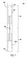
- FIG. 1illustrates an exemplary dual polarized, high-gain, omnidirectional antenna system in accordance with an embodiment of the present invention.
- FIG. 2Aillustrates the individual components of antenna system as referenced in FIG. 1 and implemented in an exemplary embodiment of the present invention including a vertically polarized omnidirectional array, two horizontally polarized omnidirectional arrays, and a feed PCB.
- FIG. 2Billustrates an alternative embodiment of the antenna system disclosed in FIG. 1 , which does not include a feed PCB.
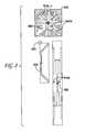
- FIG. 3illustrates an exemplary vertically polarized omnidirectional array as may be implemented in an embodiment of the present invention.
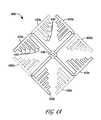
- FIG. 4Aillustrates a square configuration of a horizontally polarized antenna array with selectable elements as may be implemented in an exemplary embodiment of the present invention.
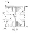
- FIG. 4Billustrates a square configuration of a horizontally polarized antenna array with selectable elements and reflector/directors as may be implemented in an alternative embodiment of the present invention.
- FIG. 4Cillustrates an exemplary antenna array including both selectively coupled antenna elements and selectively coupled reflector/directors as may be implemented in an alternative embodiment of the present invention.
- FIG. 4Dillustrates a triangular configuration of a horizontally polarized antenna array with selectable elements as may be implemented in an alternative embodiment of the present invention.
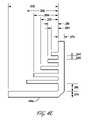
- FIG. 4Eillustrates an exemplary set of dimensions for one antenna element of the horizontally polarized antenna array shown in FIG. 4A and in accordance with an exemplary embodiment of the present invention.
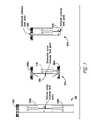
- FIG. 5illustrates a series of low-gain antenna arrays in accordance with alternative embodiments of the present invention.
- FIG. 6illustrates a series of radiation patterns that may result from implementation of various embodiments of the present invention.
- FIG. 7illustrates plots of a series of measured radiation patterns with respect to a horizontal and vertical antenna array.
- FIG. 8illustrates exemplary antenna structure mechanicals for coupling the various antenna arrays and PCB feeds disclosed in various embodiments of the present invention.
- FIG. 9illustrates alternative antenna structure mechanicals for coupling more than one vertical antenna array to a horizontal array wherein the coupling includes a plurality of slots in the PCB of the horizontal array.
- FIG. 1illustrates an exemplary dual polarized, high-gain, omnidirectional antenna system 100 in accordance with an embodiment of the present invention.
- Any reference to the presently disclosed antenna systems being coaxial in natureshould not be interpreted (exclusively) as an antenna element consisting of a hollow conducting tube through which a coaxial cable is passed.
- two horizontal antenna arrays sharing a common axis including a vertical antenna arrayare disclosed. Such systems are coaxial to the extent that those horizontal arrays share the aforementioned common vertical axis formed by the vertical array although other configurations are envisioned.
- various cabling mechanismsmay be used with respect to a communications device implementing the presently disclosed dual polarized, high-gain, omnidirectional antenna system 100 including a coaxial feed.
- a vertical arraymay be coupled to another antenna array positioned at a 45 degree angle with respect to the vertical array. Utilizing various intersection angles with respect to the two or more arrays may further allow for the shaping of a particular RF emission pattern.
- FIG. 2Aillustrates the individual components of antenna system 100 as referenced in FIG. 1 and implemented in an exemplary embodiment of the present invention.
- Antenna system 100 as illustrated in FIG. 1includes a vertically polarized omnidirectional array 210 , detailed in FIG. 3 below.
- Antenna system 100 as illustrated in FIG. 1also includes at least one horizontally polarized omnidirectional antenna array 220 , discussed in detail with respect to FIGS. 4A-4D .
- Antenna system 100 as shown in FIG. 1further includes a feed PCB 230 for coupling, for example, two horizontally polarized omnidirectional antenna arrays like array 220 .
- a different radiomay be coupled to each of the different polarizations.
- the radiation patterns generated by the varying arraysmay be substantially similar with respect to a particular RF emission pattern.
- the radiation patterns generated by the horizontal and the vertical arraymay be substantially dissimilar versus one another.
- the vertically polarized array 210may include two or more vertically polarized elements as is illustrated in detail with respect to FIG. 3 .
- the two vertically polarized elementsmay be coupled to form vertically polarized array 210 .
- the vertically polarized arrayis omnidirectional.
- Feed PCB 230couples the horizontally polarized antenna arrays 220 like those illustrated in FIG. 1 .
- the feed PCB 230may couple horizontally polarized omnidirectional arrays at a feed slot 240 located on horizontal array 220 .
- the feed PCB 230may couple each horizontally polarized omnidirectional antenna array 220 at any place on, or slot within, the antenna or supporting PCB.
- the feed PCB 230may be soldered to horizontal antenna array 220 at intersecting trace elements in the PCB. For example, an RF trace in the horizontal array may intersect with a similar trace in the vertical array through intersecting of the arrays as discussed, for example, in the context of FIG. 8 .
- an intermediate componentmay be introduced at the trace element interconnect such as a zero Ohm resistor jumper.
- the zero Ohm resistor jumpereffectively operates as a wire link that may be easier to manage with respect to size, particular antenna array positioning and configuration and, further, with respect to costs that may be incurred during the manufacturing process versus, for example, the use of aforementioned feed PCB 230 . Direct soldering of the traces may also occur. While the feed PCB 230 illustrated in FIGS. 1 and 2A couples two horizontal antenna arrays 220 , the horizontal arrays 220 may be further coupled or individually coupled to the vertically polarized antenna array 210 or elements thereof utilizing the techniques discussed above and in the context of FIG. 8 .
- the coupling of the two (or more) arrays via the aforementioned tracesmay allow for an RF feed to traverse two disparate arrays.
- the RF feedmay ‘jump’ the horizontally polarized array to the vertically polarized array.
- Such ‘jumping’may occur in the context of various intermediate elements including a zero Ohm resistor and/or a connector tab as discussed herein.
- FIG. 2Billustrates an alternative embodiment of the antenna system disclosed in FIG. 1 , which does not include a feed PCB.
- the embodiment of FIG. 2Bincludes the aforementioned horizontal arrays 220 a and 220 b and the vertical arrays 210 a and 210 b .
- the various arraysmay be coupled to one another through a combination of insertion of arrays through various PCB slits as discussed in the context of FIG. 8 and soldering/jumping feed traces as discussed herein.
- the inset of FIG. 2Billustrates where such array-to-array coupling may occur.
- FIG. 3illustrates an exemplary vertically polarized omnidirectional array 210 like that shown in FIGS. 1 and 2 and including two antenna elements 310 and 320 as may be implemented in an embodiment of the present invention.
- the vertically polarized omnidirectional antenna elements 310 and 320 of antenna array 210may be formed on substrate 330 having a first side 340 and a second side 350 .
- the portions of the vertically polarized omnidirectional array 210 depicted in a dark line 310 a in FIG. 3may be on one side ( 340 ) of the substrate.
- the portions of the vertically polarized omnidirectional array 210 depicted as dashed lines 320 a in FIG. 3may be on the other side ( 350 ) of the substrate 330 .
- the substrate 330comprises a PCB such as FR4, Rogers 4003, or other dielectric material.
- the vertically polarized omnidirectional antenna elements 310 and 320 of antenna array 210 in FIG. 3are coupled to a feed port 360 .
- the feed portis depicted as a small circle at the base of the vertically polarized omnidirectional array element 310 in FIG. 3 .
- the feed port 360may be configured to receive and/or transmit an RF signal to a communications device and a coupling network (not shown) for selecting one or more of the antenna elements.
- the RF signalmay be received from, for example, an RF coaxial cable coupled to the aforementioned coupling network.
- the coupling networkmay comprise DC blocking capacitors and active RF switches to couple the radio frequency feed port 360 to one or more of the antenna elements.
- the RF switchesmay include a PIN diode or gallium arsenide field-effect transistor (GaAs FET) or other switching devices as are known in the art.
- the PIN diodesmay comprise single-pole single-throw switches to switch each antenna element either on or off (i.e., couple or decouple each of the antenna elements to the feed port 360 ).
- FIG. 4Aillustrates a square configuration of a horizontally polarized antenna array 400 with selectable elements as may be implemented in an exemplary embodiment of the present invention.
- horizontally polarized antenna array 400includes a substrate (the plane of FIG. 4A ) having a first side (solid lines 410 ) and a second side (dashed lines 420 ) that may be substantially parallel to the first side.
- the substratemay comprise, for example, a PCB such as FR4, Rogers 4003 or some other dielectric material.
- the antenna array 400includes a radio frequency feed port 430 and four antenna elements 410 a - 410 d .
- antenna elements 410 a - 410 dare depicted in FIG. 4A , more or fewer antenna elements may be implemented with respect to array 400 .
- antenna elements 410 a - 410 d of FIG. 4Aare oriented substantially to the edges of a square shaped substrate thereby minimizing the size of the antenna array 400 , other shapes may be implemented. In some embodiments, the elements may be positioned substantially to the middle or center of the substrate.
- FIG. 4Dillustrates a triangular configuration of a horizontally polarized antenna array with selectable elements as may be implemented in an alternative embodiment of the present invention.
- Each side of the triangular horizontally polarized antenna arraymay be equal or proportional to a side of the square horizontally polarized antenna array 400 as shown in FIG. 4A .
- Other embodimentsmay implement unequal or otherwise non-proportional sides with respect to the exemplary square configurations illustrated in, for example, FIGS. 4A .
- the antenna elements on the triangular arraylike its square-shaped counterpart, may be positioned substantially to the edge or the middle/center of the array.
- the antenna elements 410 a - 410 dform a radially symmetrical layout about the radio frequency feed port 430 , a number of non-symmetrical layouts, rectangular layouts, and/or layouts symmetrical in only one axis, may be implemented. Furthermore, the antenna elements 410 a - 410 d need not be of identical dimension notwithstanding FIG. 4 A's depiction of the same.
- the antenna array 400includes a ground component 420 .
- a portion of the ground component 420(e.g., the portion 420 a ) may be configured to form a modified dipole in conjunction with the antenna element 410 a .
- the dipoleis completed for each of the antenna elements 410 a - 410 d by respective conductive traces 420 a - 420 d extending in mutually opposite directions.
- the resultant modified dipoleprovides a horizontally polarized directional radiation pattern (i.e., substantially in the plane of the antenna array 400 ), as illustrated in, for example, FIG. 7 .
- each of the modified dipolesmay incorporate one or more loading structures 440 .
- the loading structures 440 for the modified dipole formed from the antenna element 410 a and the portion 420 aare numbered in FIG. 4A .
- the modified dipolebecomes electrically shorter. In other words, at a given operating frequency, providing the loading structures 440 reduces the dimension of the modified dipole.
- Providing the loading structures 440 for one or more of the modified dipoles of the antenna array 400minimizes the size of the antenna array 440 .
- FIG. 4Billustrates a square configuration of a horizontally polarized antenna array 400 with selectable elements and reflector/directors as may be implemented in an alternative embodiment of the present invention.
- the antenna array 400 of FIG. 4Bincludes one or more reflector/directors 450 .
- the reflector/directors 450comprise passive elements (versus an active element radiating RF energy) that constrain the directional radiation pattern of the modified dipoles formed by antenna elements 415 a in conjunction with portions 425 a of the ground component. For the sake of clarity, only element 415 a and portion 425 a are labeled in FIG. 4B . Because of the reflector/directors 450 , the antenna elements 415 and the portions 425 are slightly different in configuration from the antenna elements 410 and portions 420 of FIG. 4A .
- Reflector/directors 250may be placed on either side of the substrate. Additional reflector/directors (not shown) may be included to further influence the directional radiation pattern of one or more of the modified dipoles.
- the antenna elementsmay be selectively or permanently coupled to a radio frequency feed port.
- the reflector/directorse.g., parasitic elements
- the reflector/directorsmay be configured such that the length of the reflector/directors may change through selective coupling of one or more reflector/directors to one another. For example, a series of interrupted and individual parasitic elements that are 100 mils in length may be selectively coupled in a manner similar to the selective coupling of the aforementioned antenna elements.
- the elementsmay effectively become reflectors that reflect and otherwise shape and influence the RF pattern emitted by the active antenna elements (e.g., back toward a drive dipole resulting in a higher gain in that direction).
- RF energy emitted by an antenna arraymay be focused through these reflectors/directors to address particular nuances of a given wireless environment.
- the parasitic elementsthrough decoupling may be made effectively transparent to any emitted radiation pattern. Similar reflector systems may be implemented on other arrays (e.g., the vertically polarized array).
- a similar implementationmay be used with respect to a director element or series of elements that may collectively operate as a director.
- a directorfocuses energy from source away from the source thereby increasing the gain of the antenna.
- both reflectors and directorscan be used to affect and influence the gain of the antenna structure. Implementation of the reflector/directors may occur on both arrays, a single array, or on certain arrays (e.g., in the case of two horizontal arrays and a single vertical array, the reflector/director system may be present only on one of the horizontal arrays or, alternatively, on neither horizontal array and only the vertical array).
- FIG. 4Cillustrates an exemplary antenna array including a series of antenna elements that are selectively coupled to a radio feed port. Additionally, the antenna array includes a series of selectively coupled parasitic elements that may collectively operate as, for example, a reflector. Depending on the particular length of the selectively coupled elements, the selectively coupled elements may also function as a director. Selective coupling of both the antenna and parasitic elements may utilize a coupling network and various intermediate elements (e.g., PIN diodes) as discussed above. Through selective coupling control of both antenna and parasitic elements, further control of an RF emission pattern and a resulting wireless environment may result.
- intermediate elementse.g., PIN diodes
- FIG. 4Eillustrates an exemplary set of dimensions for one antenna element of the horizontally polarized antenna array 400 shown in FIG. 4A and in accordance with an exemplary embodiment of the present invention.
- the dimensions of individual components of the antenna array 400may depend upon a desired operating frequency of the antenna array 400 .
- RF simulation softwaree.g., IE3D from Zeland Software, Inc.
- the antenna component dimensions of the antenna array 400 illustrated in FIG. 4Eare designed for operation near 2.4 GHz based on a Rogers 4003 PCB substrate.
- a different substrate having different dielectric properties, such as FR4may require different dimensions than those shown in FIG. 4E .
- radio frequency feed port 430receives an RF signal from and/or transmits an RF signal to a communication device (not shown) in a fashion similar to that of the feed port 360 illustrated in FIG. 3 .
- the communication devicemay include virtually any device for generating and/or receiving an RF signal.
- the communication devicemay include, for example, a radio modulator/demodulator.
- the communications devicemay also include a transmitter and/or receiver such as an 802.11 access point, an 802.11 receiver, a set-top box, a laptop computer, an IP-enabled television, a PCMCIA card, a remote control, a Voice Over Internet telephone or a remote terminal such as a handheld gaming device.
- the communication devicemay include circuitry for receiving data packets of video from a router and circuitry for converting the data packets into 802.11 compliant RF signals as are known in the art.
- the communications devicemay comprise an access point for communicating to one or more remote receiving nodes (not shown) over a wireless link, for example in an 802.11 wireless network.
- the devicemay also form a part of a wireless local area network by enabling communications among several remote receiving nodes.
- an antenna element selectormay be used to couple the radio frequency feed port 430 to one or more of the antenna elements 410 .
- the antenna element selectormay comprise an RF switch (not shown), such as a PIN diode, a GaAs FET, or other RF switching devices as known in the art.
- the antenna element selectorcomprises four PIN diodes, each PIN diode connecting one of the antenna elements 410 a - 410 d to the radio frequency feed port 430 .
- the PIN diodecomprises a single-pole single-throw switch to switch each antenna element either on or off (i.e., couple or decouple each of the antenna elements 410 a - 410 d to the radio frequency feed port 430 ).
- a series of control signalsmay be used to bias each PIN diode. With the PIN diode forward biased and conducting a DC current, the PIN diode switch is on, and the corresponding antenna element is selected. With the diode reverse biased, the PIN diode switch is off.
- the radio frequency feed port 430 and the PIN diodes of the antenna element selectorare on the side of the substrate with the antenna elements 410 a - 410 d , however, other embodiments separate the radio frequency feed port 430 , the antenna element selector, and the antenna elements 410 a - 410 d.
- one or more light emitting diodesare coupled to the antenna element selector.
- the LEDsfunction as a visual indicator of which of the antenna elements 410 a - 410 d is on or off.
- an LEDis placed in circuit with the PIN diode so that the LED is lit when the corresponding antenna element 410 is selected.
- the antenna componentsare formed from RF conductive material.
- the antenna elements 410 a - 410 d and the ground component 420may be formed from metal or other RF conducting material.
- each antenna element 410 a - 410 dis coplanar with the ground component 420 .
- the antenna componentsmay be conformally mounted to a housing.
- the antenna element selectorcomprises a separate structure (not shown) from the antenna elements 410 a - 410 d .
- the antenna element selectormay be mounted on a relatively small PCB, and the PCB may be electrically coupled to the antenna elements 410 - 410 d .
- the switch PCBis soldered directly to the antenna elements 410 a - 410 d.
- the antenna arraysare designed to operate over a frequency range of about 2.4 GHz to 2.4835 GHz. With all four antenna elements 410 a - 410 d selected to result in an omnidirectional radiation pattern, the combined frequency response of the antenna array 400 is about 90 MHz. In some embodiments, coupling more than one of the antenna elements 410 a - 410 d to the radio frequency feed port 430 maintains a match with less than 10 dB return loss over 802.11 wireless LAN frequencies, regardless of the number of antenna elements 410 a - 410 d that are switched on.
- Selectable antenna elements 410 a - 410 dmay be combined to result in a combined radiation pattern that is less directional than the radiation pattern of a single antenna element. For example, selecting all of the antenna elements 410 a - 410 d results in a substantially omnidirectional radiation pattern that has less directionality than the directional radiation pattern of a single antenna element. Similarly, selecting two or more antenna elements (e.g., the antenna element 410 a and the antenna element 410 c oriented opposite from each other) may result in a substantially omnidirectional radiation pattern.
- selecting a subset of the antenna elements 410 a - 410 d , or substantially all of the antenna elements 410 a - 410 dmay result in a substantially omnidirectional radiation pattern for the antenna array 400 .
- Reflector/directors 450may further constrain the directional radiation pattern of one or more of the antenna elements 410 a - 410 d in azimuth.
- FIG. 5illustrates a series of low-gain antenna arrays in accordance with alternative embodiments of the present invention.
- a horizontally polarized omnidirectional array 520is coupled to two vertically polarized omnidirectional arrays 530 a and 530 b .
- the vertically polarized omnidirectional arrays( 530 a and 530 b ) may produce a higher gain radiation pattern while the horizontally polarized omnidirectional arrays 520 may produce a lower gain radiation pattern.
- a feed PCB 550is coupled to the two horizontally polarized omnidirectional arrays 560 a and 560 b , which are (in turn) coupled to the one vertically polarized omnidirectional array 570 .
- the feed PCB 550 and two horizontally polarized omnidirectional arrays 560 a and 560 bmay produce a higher gain radiation pattern while the vertically polarized omnidirectional array 570 produces a lower gain radiation pattern.
- a single horizontally polarized omnidirectional array 590may be coupled to one vertically polarized omnidirectional array 595 .
- the horizontally polarized omnidirectional array 590 and the vertically polarized omnidirectional array 595may each produce a lower gain radiation pattern.
- FIG. 6illustrates a series of possible radiation patterns that may result from implementation of various embodiments of the present invention.
- a single vertical antenna array 620emits a low-gain radiation pattern.
- a single horizontal array 640emits a similar low-gain radiation pattern.
- a dual vertical array of antenna elements 660 a and 660 bemits a higher gain radiation pattern 650 as does a pair of horizontal antenna elements 680 a and 680 b coupled by a PCB feed line 690 with respect to pattern 670 .
- FIG. 7illustrates plots of a series of measured radiation patterns 700 .
- plot 710illustrates exemplary measured radiation patterns with respect to an exemplary horizontal array.
- plot 720illustrates exemplary measured radiation patterns with respect to an exemplary vertical antenna array.
- FIG. 8illustrates exemplary antenna structure mechanicals for coupling the various antenna arrays and PCB feeds disclosed in various embodiments of the present invention.
- Small rectangular slits 810 a - 810 cmay be formed within the PCB of a horizontally polarized omnidirectional array 820 .
- small rectangular slitsmay be formed within the PCB of a vertically polarized omnidirectional array 830 .
- the vertically polarized omnidirectional array 830may fit inside one of the slits 810 c of the horizontally polarized omnidirectional array 820 .
- Connector tabs 840 a of the vertically polarized omnidirectional array 830may be soldered to connector tabs 840 b of the horizontally polarized omnidirectional array 820 .
- the connector tabscomprise copper.
- One or more vertically polarized omnidirectional arrays 830may fit within the horizontally polarized omnidirectional array 820 via the slits 810 a - 810 c .
- the coupling of the two (or more) arrays via the connector tabmay allow for an RF feed to traverse two disparate arrays. For example, the RF feed may ‘jump’ the horizontally polarized array to the vertically polarized array.
- One or more feed PCBs 850may also fit into a small slit 860 within the horizontally polarized omnidirectional array 820 . Specifically, a specifically configured portion 870 of the feed PCB 850 fits within small slit 860 .
- One or more feed PCBs 850may be coupled to the horizontally polarized omnidirectional array 820 in this fashion. In other embodiments, one or more feed PCBs 850 may be coupled to the vertically polarized omnidirectional array 830 .
- the aforementioned connector tab/soldering methodologymay also be used in this regard.
- one or more horizontally polarized omnidirectional arrays 820may be coupled to one or more vertically polarized omnidirectional arrays 830 in any number of ways.
- the feed PCB 850may be coupled to one or more horizontally polarized omnidirectional arrays 820 and/or one or more vertically polarized omnidirectional arrays 830 .
- FIG. 9illustrates alternative antenna structure mechanicals for coupling more than one vertical antenna array to a horizontal array wherein the coupling includes a plurality of slots in the PCB of the horizontal array.
- the horizontal array 910includes multiple slots 920 for receiving a vertical array 930 .
- the actual coupling of the horizontal 910 and vertical array 930may occur in a fashion similar to those disclosed above (e.g., direct soldering at a trace and/or use of a jumper resistor).
- embodiments disclosed hereinare illustrative. Various modifications or adaptations of the structures and methods described herein may become apparent to those skilled in the art.
- embodiments of the present inventionmay be used with respect to MIMO wireless technologies that use multiple antennas as the transmitter and/or receiver to produce significant capacity gains over single-input and single-output (SISO) systems using the same bandwidth and transmit power. Examples of such MIMO antenna systems are disclosed in U.S. provisional patent application No. 60/865,148, which has previously been incorporated herein by reference.
- Such modifications, adaptations, and/or variationsthat rely upon the teachings of the present disclosure and through which these teachings have advanced the art are considered to be within the spirit and scope of the present invention.
- the descriptions and drawings hereinshould be limited by reference to the specific limitations set forth in the claims appended hereto.
Landscapes
- Physics & Mathematics (AREA)
- Electromagnetism (AREA)
- Variable-Direction Aerials And Aerial Arrays (AREA)
- Aerials With Secondary Devices (AREA)
Abstract
Description
Claims (19)
Priority Applications (7)
| Application Number | Priority Date | Filing Date | Title |
|---|---|---|---|
| US12/396,439US7880683B2 (en) | 2004-08-18 | 2009-03-02 | Antennas with polarization diversity |
| US12/604,832US7965252B2 (en) | 2004-08-18 | 2009-10-23 | Dual polarization antenna array with increased wireless coverage |
| US12/605,256US8031129B2 (en) | 2004-08-18 | 2009-10-23 | Dual band dual polarization antenna array |
| US13/019,214US9077071B2 (en) | 2004-08-18 | 2011-02-01 | Antenna with polarization diversity |
| US13/240,687US8314749B2 (en) | 2004-08-18 | 2011-09-22 | Dual band dual polarization antenna array |
| US13/681,421US8860629B2 (en) | 2004-08-18 | 2012-11-20 | Dual band dual polarization antenna array |
| US14/792,052US10181655B2 (en) | 2004-08-18 | 2015-07-06 | Antenna with polarization diversity |
Applications Claiming Priority (6)
| Application Number | Priority Date | Filing Date | Title |
|---|---|---|---|
| US60315704P | 2004-08-18 | 2004-08-18 | |
| US60271104P | 2004-08-18 | 2004-08-18 | |
| US11/041,145US7362280B2 (en) | 2004-08-18 | 2005-01-21 | System and method for a minimized antenna apparatus with selectable elements |
| US75344205P | 2005-12-23 | 2005-12-23 | |
| US11/646,136US7498996B2 (en) | 2004-08-18 | 2006-12-26 | Antennas with polarization diversity |
| US12/396,439US7880683B2 (en) | 2004-08-18 | 2009-03-02 | Antennas with polarization diversity |
Related Parent Applications (1)
| Application Number | Title | Priority Date | Filing Date |
|---|---|---|---|
| US11/646,136ContinuationUS7498996B2 (en) | 2004-08-18 | 2006-12-26 | Antennas with polarization diversity |
Related Child Applications (4)
| Application Number | Title | Priority Date | Filing Date |
|---|---|---|---|
| US12/605,256Continuation-In-PartUS8031129B2 (en) | 2004-08-18 | 2009-10-23 | Dual band dual polarization antenna array |
| US12/605,256ContinuationUS8031129B2 (en) | 2004-08-18 | 2009-10-23 | Dual band dual polarization antenna array |
| US12/604,832Continuation-In-PartUS7965252B2 (en) | 2004-08-18 | 2009-10-23 | Dual polarization antenna array with increased wireless coverage |
| US13/019,214ContinuationUS9077071B2 (en) | 2004-08-18 | 2011-02-01 | Antenna with polarization diversity |
Publications (2)
| Publication Number | Publication Date |
|---|---|
| US20100053010A1 US20100053010A1 (en) | 2010-03-04 |
| US7880683B2true US7880683B2 (en) | 2011-02-01 |
Family
ID=41724571
Family Applications (3)
| Application Number | Title | Priority Date | Filing Date |
|---|---|---|---|
| US12/396,439Expired - LifetimeUS7880683B2 (en) | 2004-08-18 | 2009-03-02 | Antennas with polarization diversity |
| US13/019,214Active2026-05-26US9077071B2 (en) | 2004-08-18 | 2011-02-01 | Antenna with polarization diversity |
| US14/792,052Expired - LifetimeUS10181655B2 (en) | 2004-08-18 | 2015-07-06 | Antenna with polarization diversity |
Family Applications After (2)
| Application Number | Title | Priority Date | Filing Date |
|---|---|---|---|
| US13/019,214Active2026-05-26US9077071B2 (en) | 2004-08-18 | 2011-02-01 | Antenna with polarization diversity |
| US14/792,052Expired - LifetimeUS10181655B2 (en) | 2004-08-18 | 2015-07-06 | Antenna with polarization diversity |
Country Status (1)
| Country | Link |
|---|---|
| US (3) | US7880683B2 (en) |
Cited By (17)
| Publication number | Priority date | Publication date | Assignee | Title |
|---|---|---|---|---|
| US20100289705A1 (en)* | 2009-05-12 | 2010-11-18 | Victor Shtrom | Mountable Antenna Elements for Dual Band Antenna |
| US20110205137A1 (en)* | 2004-08-18 | 2011-08-25 | Victor Shtrom | Antenna with Polarization Diversity |
| US20110228870A1 (en)* | 2006-02-28 | 2011-09-22 | Rotani, Inc. | Method and Apparatus for Overlapping MIMO Physical Sectors |
| US8314749B2 (en) | 2004-08-18 | 2012-11-20 | Ruckus Wireless, Inc. | Dual band dual polarization antenna array |
| US8422540B1 (en) | 2012-06-21 | 2013-04-16 | CBF Networks, Inc. | Intelligent backhaul radio with zero division duplexing |
| US8467363B2 (en) | 2011-08-17 | 2013-06-18 | CBF Networks, Inc. | Intelligent backhaul radio and antenna system |
| US20130249761A1 (en)* | 2010-09-27 | 2013-09-26 | Tian Hong Loh | Smart Antenna for Wireless Communications |
| US20150207238A1 (en)* | 2014-01-20 | 2015-07-23 | Rf Micro Devices, Inc. | Multiple-input multiple-output rf antenna architectures |
| US9287633B2 (en) | 2012-08-30 | 2016-03-15 | Industrial Technology Research Institute | Dual frequency coupling feed antenna and adjustable wave beam module using the antenna |
| US9407012B2 (en) | 2010-09-21 | 2016-08-02 | Ruckus Wireless, Inc. | Antenna with dual polarization and mountable antenna elements |
| US9570799B2 (en) | 2012-09-07 | 2017-02-14 | Ruckus Wireless, Inc. | Multiband monopole antenna apparatus with ground plane aperture |
| US9577346B2 (en) | 2005-06-24 | 2017-02-21 | Ruckus Wireless, Inc. | Vertical multiple-input multiple-output wireless antennas |
| US10090591B2 (en) | 2016-04-20 | 2018-10-02 | Accton Technology Corporation | Antenna system |
| US10230161B2 (en) | 2013-03-15 | 2019-03-12 | Arris Enterprises Llc | Low-band reflector for dual band directional antenna |
| US10985458B2 (en) | 2017-09-25 | 2021-04-20 | Huawei Technologies Co., Ltd. | Antenna apparatus and terminal device |
| US11978963B2 (en) | 2019-09-18 | 2024-05-07 | Huawei Technologies Co., Ltd. | Beam diversity by smart antenna with passive elements |
| US12068543B2 (en) | 2019-09-18 | 2024-08-20 | Huawei Technologies Co., Ltd. | Beam diversity by smart antenna without passive elements |
Families Citing this family (53)
| Publication number | Priority date | Publication date | Assignee | Title |
|---|---|---|---|---|
| US8934416B2 (en)* | 2005-03-09 | 2015-01-13 | Xirrus, Inc. | System for allocating channels in a multi-radio wireless LAN array |
| US9088907B2 (en)* | 2007-06-18 | 2015-07-21 | Xirrus, Inc. | Node fault identification in wireless LAN access points |
| US8482478B2 (en)* | 2008-11-12 | 2013-07-09 | Xirrus, Inc. | MIMO antenna system |
| US8878744B2 (en) | 2010-09-20 | 2014-11-04 | MP Antenna, Ltd. | Antenna assembly providing a global multi-directional radiation pattern |
| US8830854B2 (en) | 2011-07-28 | 2014-09-09 | Xirrus, Inc. | System and method for managing parallel processing of network packets in a wireless access device |
| US8868002B2 (en) | 2011-08-31 | 2014-10-21 | Xirrus, Inc. | System and method for conducting wireless site surveys |
| US9055450B2 (en) | 2011-09-23 | 2015-06-09 | Xirrus, Inc. | System and method for determining the location of a station in a wireless environment |
| US10186750B2 (en)* | 2012-02-14 | 2019-01-22 | Arris Enterprises Llc | Radio frequency antenna array with spacing element |
| WO2013173250A1 (en) | 2012-05-13 | 2013-11-21 | Invention Mine Llc | Full duplex wireless transmission with self-interference cancellation |
| US9997830B2 (en) | 2012-05-13 | 2018-06-12 | Amir Keyvan Khandani | Antenna system and method for full duplex wireless transmission with channel phase-based encryption |
| US9179336B2 (en) | 2013-02-19 | 2015-11-03 | Mimosa Networks, Inc. | WiFi management interface for microwave radio and reset to factory defaults |
| US9930592B2 (en) | 2013-02-19 | 2018-03-27 | Mimosa Networks, Inc. | Systems and methods for directing mobile device connectivity |
| WO2014137370A1 (en) | 2013-03-06 | 2014-09-12 | Mimosa Networks, Inc. | Waterproof apparatus for cables and cable interfaces |
| US9362629B2 (en) | 2013-03-06 | 2016-06-07 | Mimosa Networks, Inc. | Enclosure for radio, parabolic dish antenna, and side lobe shields |
| US10742275B2 (en)* | 2013-03-07 | 2020-08-11 | Mimosa Networks, Inc. | Quad-sector antenna using circular polarization |
| US9191081B2 (en) | 2013-03-08 | 2015-11-17 | Mimosa Networks, Inc. | System and method for dual-band backhaul radio |
| US10177896B2 (en) | 2013-05-13 | 2019-01-08 | Amir Keyvan Khandani | Methods for training of full-duplex wireless systems |
| US9295103B2 (en) | 2013-05-30 | 2016-03-22 | Mimosa Networks, Inc. | Wireless access points providing hybrid 802.11 and scheduled priority access communications |
| US10938110B2 (en) | 2013-06-28 | 2021-03-02 | Mimosa Networks, Inc. | Ellipticity reduction in circularly polarized array antennas |
| US9236996B2 (en) | 2013-11-30 | 2016-01-12 | Amir Keyvan Khandani | Wireless full-duplex system and method using sideband test signals |
| US9001689B1 (en) | 2014-01-24 | 2015-04-07 | Mimosa Networks, Inc. | Channel optimization in half duplex communications systems |
| US9820311B2 (en) | 2014-01-30 | 2017-11-14 | Amir Keyvan Khandani | Adapter and associated method for full-duplex wireless communication |
| US9780892B2 (en) | 2014-03-05 | 2017-10-03 | Mimosa Networks, Inc. | System and method for aligning a radio using an automated audio guide |
| US9998246B2 (en) | 2014-03-13 | 2018-06-12 | Mimosa Networks, Inc. | Simultaneous transmission on shared channel |
| US9257419B2 (en)* | 2014-03-17 | 2016-02-09 | Freescale Semiconductor Inc. | Leadframe-based system-in-packages having sidewall-mounted surface mount devices and methods for the production thereof |
| KR102172187B1 (en)* | 2014-08-22 | 2020-10-30 | 주식회사 케이엠더블유 | Omni-directional antenna for mobile communication service |
| USD759635S1 (en)* | 2014-09-08 | 2016-06-21 | Avery Dennison Corporation | Antenna |
| US10958332B2 (en) | 2014-09-08 | 2021-03-23 | Mimosa Networks, Inc. | Wi-Fi hotspot repeater |
| USD769228S1 (en)* | 2014-10-24 | 2016-10-18 | R.R. Donnelley & Sons Company | Antenna |
| US10084243B2 (en)* | 2014-11-28 | 2018-09-25 | Galtronics Corporation Ltd. | Antenna isolator |
| CN105186099B (en)* | 2015-07-14 | 2017-12-12 | 中磊电子(苏州)有限公司 | Anneta module |
| WO2017123558A1 (en) | 2016-01-11 | 2017-07-20 | Mimosa Networks, Inc. | Printed circuit board mounted antenna and waveguide interface |
| CN105680168B (en)* | 2016-01-14 | 2018-04-06 | 西北工业大学 | A kind of intersecting parallels paster two-terminal feeding high-isolation flat plane antenna |
| US10333593B2 (en) | 2016-05-02 | 2019-06-25 | Amir Keyvan Khandani | Systems and methods of antenna design for full-duplex line of sight transmission |
| CN105932415A (en)* | 2016-06-06 | 2016-09-07 | 佛山澳信科技有限公司 | Omnidirectional microstrip antenna |
| CN109417407B (en)* | 2016-07-15 | 2022-01-18 | 梁平 | MIMO coupler array with high degree of freedom |
| US11251539B2 (en) | 2016-07-29 | 2022-02-15 | Airspan Ip Holdco Llc | Multi-band access point antenna array |
| CN108155473B (en)* | 2016-12-06 | 2024-05-14 | 普罗斯通信技术(苏州)有限公司 | Feed structure and base station antenna |
| US10700766B2 (en) | 2017-04-19 | 2020-06-30 | Amir Keyvan Khandani | Noise cancelling amplify-and-forward (in-band) relay with self-interference cancellation |
| US11057204B2 (en) | 2017-10-04 | 2021-07-06 | Amir Keyvan Khandani | Methods for encrypted data communications |
| CN107863605B (en)* | 2017-10-17 | 2024-01-09 | 广东盛路通信科技股份有限公司 | Multi-integrated CPE MIMO antenna |
| CN107768802B (en)* | 2017-11-22 | 2024-06-04 | 广东通宇通讯股份有限公司 | Antenna |
| US10511074B2 (en) | 2018-01-05 | 2019-12-17 | Mimosa Networks, Inc. | Higher signal isolation solutions for printed circuit board mounted antenna and waveguide interface |
| US11012144B2 (en) | 2018-01-16 | 2021-05-18 | Amir Keyvan Khandani | System and methods for in-band relaying |
| US11069986B2 (en) | 2018-03-02 | 2021-07-20 | Airspan Ip Holdco Llc | Omni-directional orthogonally-polarized antenna system for MIMO applications |
| US11289821B2 (en) | 2018-09-11 | 2022-03-29 | Air Span Ip Holdco Llc | Sector antenna systems and methods for providing high gain and high side-lobe rejection |
| US10651565B1 (en) | 2019-04-29 | 2020-05-12 | Microsoft Technology Licensing, Llc | Antenna polarization diversity |
| US10985473B2 (en) | 2019-08-30 | 2021-04-20 | City University Of Hong Kong | Dielectric resonator antenna |
| US11005191B1 (en)* | 2019-11-06 | 2021-05-11 | Pc-Tel, Inc. | Omni-directional horizontally polarized antenna system |
| CN112072287B (en)* | 2020-09-03 | 2022-09-27 | 武汉凡谷电子技术股份有限公司 | Dual-polarized antenna module |
| USD980199S1 (en)* | 2020-12-17 | 2023-03-07 | Megabyte Limited | Antenna for radio frequency tag reader |
| US11575858B2 (en)* | 2021-02-26 | 2023-02-07 | Comcast Cable Communications, Llc | Video device with electromagnetically reflective elements |
| USD1025036S1 (en)* | 2023-02-07 | 2024-04-30 | Impinj, Inc. | Single-port omnidirectional antenna |
Citations (208)
| Publication number | Priority date | Publication date | Assignee | Title |
|---|---|---|---|---|
| US723188A (en) | 1900-07-16 | 1903-03-17 | Nikola Tesla | Method of signaling. |
| US1869659A (en) | 1929-10-12 | 1932-08-02 | Broertjes Willem | Method of maintaining secrecy in the transmission of wireless telegraphic messages |
| US2292387A (en) | 1941-06-10 | 1942-08-11 | Markey Hedy Kiesler | Secret communication system |
| US3488445A (en) | 1966-11-14 | 1970-01-06 | Bell Telephone Labor Inc | Orthogonal frequency multiplex data transmission system |
| US3568105A (en) | 1969-03-03 | 1971-03-02 | Itt | Microstrip phase shifter having switchable path lengths |
| US3967067A (en) | 1941-09-24 | 1976-06-29 | Bell Telephone Laboratories, Incorporated | Secret telephony |
| US3982214A (en) | 1975-10-23 | 1976-09-21 | Hughes Aircraft Company | 180° phase shifting apparatus |
| US3991273A (en) | 1943-10-04 | 1976-11-09 | Bell Telephone Laboratories, Incorporated | Speech component coded multiplex carrier wave transmission |
| US4001734A (en) | 1975-10-23 | 1977-01-04 | Hughes Aircraft Company | π-Loop phase bit apparatus |
| US4176356A (en) | 1977-06-27 | 1979-11-27 | Motorola, Inc. | Directional antenna system including pattern control |
| US4193077A (en) | 1977-10-11 | 1980-03-11 | Avnet, Inc. | Directional antenna system with end loaded crossed dipoles |
| US4253193A (en) | 1977-11-05 | 1981-02-24 | The Marconi Company Limited | Tropospheric scatter radio communication systems |
| US4305052A (en) | 1978-12-22 | 1981-12-08 | Thomson-Csf | Ultra-high-frequency diode phase shifter usable with electronically scanning antenna |
| US4513412A (en) | 1983-04-25 | 1985-04-23 | At&T Bell Laboratories | Time division adaptive retransmission technique for portable radio telephones |
| US4554554A (en) | 1983-09-02 | 1985-11-19 | The United States Of America As Represented By The Secretary Of The Navy | Quadrifilar helix antenna tuning using pin diodes |
| US4733203A (en) | 1984-03-12 | 1988-03-22 | Raytheon Company | Passive phase shifter having switchable filter paths to provide selectable phase shift |
| US4814777A (en) | 1987-07-31 | 1989-03-21 | Raytheon Company | Dual-polarization, omni-directional antenna system |
| US5063574A (en) | 1990-03-06 | 1991-11-05 | Moose Paul H | Multi-frequency differentially encoded digital communication for high data rate transmission through unequalized channels |
| US5097484A (en) | 1988-10-12 | 1992-03-17 | Sumitomo Electric Industries, Ltd. | Diversity transmission and reception method and equipment |
| US5173711A (en) | 1989-11-27 | 1992-12-22 | Kokusai Denshin Denwa Kabushiki Kaisha | Microstrip antenna for two-frequency separate-feeding type for circularly polarized waves |
| EP0534612A2 (en) | 1991-08-28 | 1993-03-31 | Motorola, Inc. | Cellular system sharing of logical channels |
| US5203010A (en) | 1990-11-13 | 1993-04-13 | Motorola, Inc. | Radio telephone system incorporating multiple time periods for communication transfer |
| US5208564A (en) | 1991-12-19 | 1993-05-04 | Hughes Aircraft Company | Electronic phase shifting circuit for use in a phased radar antenna array |
| US5220340A (en) | 1992-04-29 | 1993-06-15 | Lotfollah Shafai | Directional switched beam antenna |
| US5282222A (en) | 1992-03-31 | 1994-01-25 | Michel Fattouche | Method and apparatus for multiple access between transceivers in wireless communications using OFDM spread spectrum |
| US5291289A (en) | 1990-11-16 | 1994-03-01 | North American Philips Corporation | Method and apparatus for transmission and reception of a digital television signal using multicarrier modulation |
| US5311550A (en) | 1988-10-21 | 1994-05-10 | Thomson-Csf | Transmitter, transmission method and receiver |
| US5373548A (en) | 1991-01-04 | 1994-12-13 | Thomson Consumer Electronics, Inc. | Out-of-range warning system for cordless telephone |
| US5507035A (en) | 1993-04-30 | 1996-04-09 | International Business Machines Corporation | Diversity transmission strategy in mobile/indoor cellula radio communications |
| US5532708A (en) | 1995-03-03 | 1996-07-02 | Motorola, Inc. | Single compact dual mode antenna |
| US5559800A (en) | 1994-01-19 | 1996-09-24 | Research In Motion Limited | Remote control of gateway functions in a wireless data communication network |
| EP0756381A2 (en) | 1995-07-24 | 1997-01-29 | Murata Manufacturing Co., Ltd. | High-frequency switch |
| US5754145A (en) | 1995-08-23 | 1998-05-19 | U.S. Philips Corporation | Printed antenna |
| US5767755A (en) | 1995-10-25 | 1998-06-16 | Samsung Electronics Co., Ltd. | Radio frequency power combiner |
| US5767809A (en) | 1996-03-07 | 1998-06-16 | Industrial Technology Research Institute | OMNI-directional horizontally polarized Alford loop strip antenna |
| US5786793A (en) | 1996-03-13 | 1998-07-28 | Matsushita Electric Works, Ltd. | Compact antenna for circular polarization |
| WO1998037590A2 (en) | 1997-02-20 | 1998-08-27 | Raytheon Company | Polarization diverse antenna for portable communication devices |
| US5802312A (en) | 1994-09-27 | 1998-09-01 | Research In Motion Limited | System for transmitting data files between computers in a wireless environment utilizing a file transfer agent executing on host system |
| US5964830A (en) | 1995-08-22 | 1999-10-12 | Durrett; Charles M. | User portal device for the world wide web to communicate with a website server |
| US5990838A (en) | 1996-06-12 | 1999-11-23 | 3Com Corporation | Dual orthogonal monopole antenna system |
| US6011450A (en) | 1996-10-11 | 2000-01-04 | Nec Corporation | Semiconductor switch having plural resonance circuits therewith |
| US6034638A (en) | 1993-05-27 | 2000-03-07 | Griffith University | Antennas for use in portable communications devices |
| US6052093A (en) | 1996-12-18 | 2000-04-18 | Savi Technology, Inc. | Small omni-directional, slot antenna |
| US6091364A (en) | 1996-06-28 | 2000-07-18 | Kabushiki Kaisha Toshiba | Antenna capable of tilting beams in a desired direction by a single feeder circuit, connection device therefor, coupler, and substrate laminating method |
| US6094177A (en) | 1997-11-27 | 2000-07-25 | Yamamoto; Kiyoshi | Planar radiation antenna elements and omni directional antenna using such antenna elements |
| US6097347A (en) | 1997-01-29 | 2000-08-01 | Intermec Ip Corp. | Wire antenna with stubs to optimize impedance for connecting to a circuit |
| US6104356A (en) | 1995-08-25 | 2000-08-15 | Uniden Corporation | Diversity antenna circuit |
| US6169523B1 (en) | 1999-01-13 | 2001-01-02 | George Ploussios | Electronically tuned helix radiator choke |
| JP2001057560A (en) | 1999-08-18 | 2001-02-27 | Hitachi Kokusai Electric Inc | Wireless LAN system |
| US6266528B1 (en) | 1998-12-23 | 2001-07-24 | Arraycomm, Inc. | Performance monitor for antenna arrays |
| US6292153B1 (en) | 1999-08-27 | 2001-09-18 | Fantasma Network, Inc. | Antenna comprising two wideband notch regions on one coplanar substrate |
| US6307524B1 (en) | 2000-01-18 | 2001-10-23 | Core Technology, Inc. | Yagi antenna having matching coaxial cable and driven element impedances |
| EP1152543A1 (en) | 1999-12-14 | 2001-11-07 | Matsushita Electric Industrial Co., Ltd. | High-frequency composite switch component |
| US6317599B1 (en) | 1999-05-26 | 2001-11-13 | Wireless Valley Communications, Inc. | Method and system for automated optimization of antenna positioning in 3-D |
| US6323810B1 (en) | 2001-03-06 | 2001-11-27 | Ethertronics, Inc. | Multimode grounded finger patch antenna |
| US20010046848A1 (en) | 1999-05-04 | 2001-11-29 | Kenkel Mark A. | Method and apparatus for predictably switching diversity antennas on signal dropout |
| US6326922B1 (en) | 2000-06-29 | 2001-12-04 | Worldspace Corporation | Yagi antenna coupled with a low noise amplifier on the same printed circuit board |
| US6337668B1 (en) | 1999-03-05 | 2002-01-08 | Matsushita Electric Industrial Co., Ltd. | Antenna apparatus |
| US6337628B2 (en) | 1995-02-22 | 2002-01-08 | Ntp, Incorporated | Omnidirectional and directional antenna assembly |
| US6339404B1 (en) | 1999-08-13 | 2002-01-15 | Rangestar Wirless, Inc. | Diversity antenna system for lan communication system |
| US6345043B1 (en) | 1998-07-06 | 2002-02-05 | National Datacomm Corporation | Access scheme for a wireless LAN station to connect an access point |
| US6356242B1 (en) | 2000-01-27 | 2002-03-12 | George Ploussios | Crossed bent monopole doublets |
| US6356243B1 (en) | 2000-07-19 | 2002-03-12 | Logitech Europe S.A. | Three-dimensional geometric space loop antenna |
| US6356905B1 (en) | 1999-03-05 | 2002-03-12 | Accenture Llp | System, method and article of manufacture for mobile communication utilizing an interface support framework |
| US20020031130A1 (en) | 2000-05-30 | 2002-03-14 | Kazuaki Tsuchiya | Multicast routing method and an apparatus for routing a multicast packet |
| US6377227B1 (en) | 1999-04-28 | 2002-04-23 | Superpass Company Inc. | High efficiency feed network for antennas |
| US20020047800A1 (en) | 1998-09-21 | 2002-04-25 | Tantivy Communications, Inc. | Adaptive antenna for use in same frequency networks |
| US6392610B1 (en) | 1999-10-29 | 2002-05-21 | Allgon Ab | Antenna device for transmitting and/or receiving RF waves |
| US6404386B1 (en) | 1998-09-21 | 2002-06-11 | Tantivy Communications, Inc. | Adaptive antenna for use in same frequency networks |
| US6407719B1 (en) | 1999-07-08 | 2002-06-18 | Atr Adaptive Communications Research Laboratories | Array antenna |
| US20020080767A1 (en) | 2000-12-22 | 2002-06-27 | Ji-Woong Lee | Method of supporting small group multicast in mobile IP |
| US6414647B1 (en) | 2001-06-20 | 2002-07-02 | Massachusetts Institute Of Technology | Slender omni-directional, broad-band, high efficiency, dual-polarized slot/dipole antenna element |
| US20020084942A1 (en) | 2001-01-03 | 2002-07-04 | Szu-Nan Tsai | Pcb dipole antenna |
| USRE37802E1 (en) | 1992-03-31 | 2002-07-23 | Wi-Lan Inc. | Multicode direct sequence spread spectrum |
| US6424311B1 (en) | 2000-12-30 | 2002-07-23 | Hon Ia Precision Ind. Co., Ltd. | Dual-fed coupled stripline PCB dipole antenna |
| US20020101377A1 (en) | 2000-12-13 | 2002-08-01 | Magis Networks, Inc. | Card-based diversity antenna structure for wireless communications |
| US20020105471A1 (en) | 2000-05-24 | 2002-08-08 | Suguru Kojima | Directional switch antenna device |
| US20020112058A1 (en) | 2000-12-01 | 2002-08-15 | Microsoft Corporation | Peer networking host framework and hosting API |
| US6442507B1 (en) | 1998-12-29 | 2002-08-27 | Wireless Communications, Inc. | System for creating a computer model and measurement database of a wireless communication network |
| US6445688B1 (en) | 2000-08-31 | 2002-09-03 | Ricochet Networks, Inc. | Method and apparatus for selecting a directional antenna in a wireless communication system |
| US6452981B1 (en) | 1996-08-29 | 2002-09-17 | Cisco Systems, Inc | Spatio-temporal processing for interference handling |
| US6456242B1 (en) | 2001-03-05 | 2002-09-24 | Magis Networks, Inc. | Conformal box antenna |
| US20020158798A1 (en) | 2001-04-30 | 2002-10-31 | Bing Chiang | High gain planar scanned antenna array |
| US20020170064A1 (en) | 2001-05-11 | 2002-11-14 | Monroe David A. | Portable, wireless monitoring and control station for use in connection with a multi-media surveillance system having enhanced notification functions |
| US6493679B1 (en) | 1999-05-26 | 2002-12-10 | Wireless Valley Communications, Inc. | Method and system for managing a real time bill of materials |
| US6496083B1 (en) | 1997-06-03 | 2002-12-17 | Matsushita Electric Industrial Co., Ltd. | Diode compensation circuit including two series and one parallel resonance points |
| US6499006B1 (en) | 1999-07-14 | 2002-12-24 | Wireless Valley Communications, Inc. | System for the three-dimensional display of wireless communication system performance |
| US6498589B1 (en) | 1999-03-18 | 2002-12-24 | Dx Antenna Company, Limited | Antenna system |
| US6507321B2 (en) | 2000-05-26 | 2003-01-14 | Sony International (Europe) Gmbh | V-slot antenna for circular polarization |
| US20030026240A1 (en) | 2001-07-23 | 2003-02-06 | Eyuboglu M. Vedat | Broadcasting and multicasting in wireless communication |
| US20030030588A1 (en) | 2001-08-10 | 2003-02-13 | Music Sciences, Inc. | Antenna system |
| US6531985B1 (en) | 2000-08-14 | 2003-03-11 | 3Com Corporation | Integrated laptop antenna using two or more antennas |
| US20030063591A1 (en) | 2001-10-03 | 2003-04-03 | Leung Nikolai K.N. | Method and apparatus for data packet transport in a wireless communication system using an internet protocol |
| US6583765B1 (en) | 2001-12-21 | 2003-06-24 | Motorola, Inc. | Slot antenna having independent antenna elements and associated circuitry |
| US6586786B2 (en) | 2000-12-27 | 2003-07-01 | Matsushita Electric Industrial Co., Ltd. | High frequency switch and mobile communication equipment |
| US20030122714A1 (en) | 2001-11-16 | 2003-07-03 | Galtronics Ltd. | Variable gain and variable beamwidth antenna (the hinged antenna) |
| US6611230B2 (en) | 2000-12-11 | 2003-08-26 | Harris Corporation | Phased array antenna having phase shifters with laterally spaced phase shift bodies |
| US20030169330A1 (en) | 2001-10-24 | 2003-09-11 | Microsoft Corporation | Network conference recording system and method including post-conference processing |
| US6625454B1 (en) | 2000-08-04 | 2003-09-23 | Wireless Valley Communications, Inc. | Method and system for designing or deploying a communications network which considers frequency dependent effects |
| US20030184490A1 (en) | 2002-03-26 | 2003-10-02 | Raiman Clifford E. | Sectorized omnidirectional antenna |
| US20030189521A1 (en) | 2002-04-05 | 2003-10-09 | Atsushi Yamamoto | Directivity controllable antenna and antenna unit using the same |
| US20030189514A1 (en) | 2001-09-06 | 2003-10-09 | Kentaro Miyano | Array antenna apparatus |
| US20030189523A1 (en) | 2002-04-09 | 2003-10-09 | Filtronic Lk Oy | Antenna with variable directional pattern |
| US6633206B1 (en) | 1999-01-27 | 2003-10-14 | Murata Manufacturing Co., Ltd. | High-frequency switch |
| US6642889B1 (en) | 2002-05-03 | 2003-11-04 | Raytheon Company | Asymmetric-element reflect array antenna |
| US20030210207A1 (en) | 2002-02-08 | 2003-11-13 | Seong-Youp Suh | Planar wideband antennas |
| US20030227414A1 (en) | 2002-03-04 | 2003-12-11 | Saliga Stephen V. | Diversity antenna for UNII access point |
| US20040014432A1 (en) | 2000-03-23 | 2004-01-22 | U.S. Philips Corporation | Antenna diversity arrangement |
| US20040017310A1 (en) | 2002-07-24 | 2004-01-29 | Sarah Vargas-Hurlston | Position optimized wireless communication |
| US20040017860A1 (en) | 2002-07-29 | 2004-01-29 | Jung-Tao Liu | Multiple antenna system for varying transmission streams |
| US20040027304A1 (en) | 2001-04-30 | 2004-02-12 | Bing Chiang | High gain antenna for wireless applications |
| US20040027291A1 (en) | 2002-05-24 | 2004-02-12 | Xin Zhang | Planar antenna and array antenna |
| US20040032378A1 (en) | 2001-10-31 | 2004-02-19 | Vladimir Volman | Broadband starfish antenna and array thereof |
| US20040036651A1 (en) | 2002-06-05 | 2004-02-26 | Takeshi Toda | Adaptive antenna unit and terminal equipment |
| US20040036654A1 (en) | 2002-08-21 | 2004-02-26 | Steve Hsieh | Antenna assembly for circuit board |
| US6701522B1 (en) | 2000-04-07 | 2004-03-02 | Danger, Inc. | Apparatus and method for portal device authentication |
| US20040041732A1 (en) | 2001-10-03 | 2004-03-04 | Masayoshi Aikawa | Multielement planar antenna |
| US20040048593A1 (en) | 2000-12-21 | 2004-03-11 | Hiroyasu Sano | Adaptive antenna receiver |
| US20040058690A1 (en) | 2000-11-20 | 2004-03-25 | Achim Ratzel | Antenna system |
| US20040061653A1 (en) | 2002-09-26 | 2004-04-01 | Andrew Corporation | Dynamically variable beamwidth and variable azimuth scanning antenna |
| US20040070543A1 (en) | 2002-10-15 | 2004-04-15 | Kabushiki Kaisha Toshiba | Antenna structure for electronic device with wireless communication unit |
| US6724346B2 (en) | 2001-05-23 | 2004-04-20 | Thomson Licensing S.A. | Device for receiving/transmitting electromagnetic waves with omnidirectional radiation |
| US6725281B1 (en) | 1999-06-11 | 2004-04-20 | Microsoft Corporation | Synchronization of controlled device state using state table and eventing in data-driven remote device control model |
| US20040080455A1 (en) | 2002-10-23 | 2004-04-29 | Lee Choon Sae | Microstrip array antenna |
| US20040095278A1 (en) | 2001-12-28 | 2004-05-20 | Hideki Kanemoto | Multi-antenna apparatus multi-antenna reception method, and multi-antenna transmission method |
| US6741219B2 (en) | 2001-07-25 | 2004-05-25 | Atheros Communications, Inc. | Parallel-feed planar high-frequency antenna |
| US6747605B2 (en) | 2001-05-07 | 2004-06-08 | Atheros Communications, Inc. | Planar high-frequency antenna |
| US20040114535A1 (en) | 2002-09-30 | 2004-06-17 | Tantivy Communications, Inc. | Method and apparatus for antenna steering for WLAN |
| US6753814B2 (en) | 2002-06-27 | 2004-06-22 | Harris Corporation | Dipole arrangements using dielectric substrates of meta-materials |
| US20040125777A1 (en) | 2001-05-24 | 2004-07-01 | James Doyle | Method and apparatus for affiliating a wireless device with a wireless local area network |
| US6762723B2 (en) | 2002-11-08 | 2004-07-13 | Motorola, Inc. | Wireless communication device having multiband antenna |
| US20040137864A1 (en) | 2003-01-09 | 2004-07-15 | Samsung Electronics Co., Ltd. | Receiving apparatus in a radio communication system using at least three transmitter antennas |
| US20040145528A1 (en) | 2003-01-23 | 2004-07-29 | Kouichi Mukai | Electronic equipment and antenna mounting printed-circuit board |
| US20040160376A1 (en) | 2003-02-10 | 2004-08-19 | California Amplifier, Inc. | Compact bidirectional repeaters for wireless communication systems |
| EP1450521A2 (en) | 2003-02-19 | 2004-08-25 | Nec Corporation | Wireless communication system and method which improves reliability and throughput of communication through retransmission timeout optimization |
| US20040190477A1 (en) | 2003-03-28 | 2004-09-30 | Olson Jonathan P. | Dynamic wireless network |
| US6801790B2 (en)* | 2001-01-17 | 2004-10-05 | Lucent Technologies Inc. | Structure for multiple antenna configurations |
| US20040203347A1 (en) | 2002-03-12 | 2004-10-14 | Hung Nguyen | Selecting a set of antennas for use in a wireless communication system |
| US6819287B2 (en) | 2002-03-15 | 2004-11-16 | Centurion Wireless Technologies, Inc. | Planar inverted-F antenna including a matching network having transmission line stubs and capacitor/inductor tank circuits |
| US20040260800A1 (en) | 1999-06-11 | 2004-12-23 | Microsoft Corporation | Dynamic self-configuration for ad hoc peer networking |
| US6839038B2 (en) | 2002-06-17 | 2005-01-04 | Lockheed Martin Corporation | Dual-band directional/omnidirectional antenna |
| US6859182B2 (en) | 1999-03-18 | 2005-02-22 | Dx Antenna Company, Limited | Antenna system |
| US6859176B2 (en) | 2003-03-14 | 2005-02-22 | Sunwoo Communication Co., Ltd. | Dual-band omnidirectional antenna for wireless local area network |
| US20050042988A1 (en) | 2003-08-18 | 2005-02-24 | Alcatel | Combined open and closed loop transmission diversity system |
| US20050041739A1 (en) | 2001-04-28 | 2005-02-24 | Microsoft Corporation | System and process for broadcast and communication with very low bit-rate bi-level or sketch video |
| US20050048934A1 (en) | 2003-08-27 | 2005-03-03 | Rawnick James J. | Shaped ground plane for dynamically reconfigurable aperture coupled antenna |
| US6876280B2 (en) | 2002-06-24 | 2005-04-05 | Murata Manufacturing Co., Ltd. | High-frequency switch, and electronic device using the same |
| US6876836B2 (en) | 2002-07-25 | 2005-04-05 | Integrated Programmable Communications, Inc. | Layout of wireless communication circuit on a printed circuit board |
| US20050074018A1 (en) | 1999-06-11 | 2005-04-07 | Microsoft Corporation | XML-based template language for devices and services |
| US6888893B2 (en) | 2001-01-05 | 2005-05-03 | Microsoft Corporation | System and process for broadcast and communication with very low bit-rate bi-level or sketch video |
| US6888504B2 (en) | 2002-02-01 | 2005-05-03 | Ipr Licensing, Inc. | Aperiodic array antenna |
| US6903686B2 (en) | 2002-12-17 | 2005-06-07 | Sony Ericsson Mobile Communications Ab | Multi-branch planar antennas having multiple resonant frequency bands and wireless terminals incorporating the same |
| US6906678B2 (en) | 2002-09-24 | 2005-06-14 | Gemtek Technology Co. Ltd. | Multi-frequency printed antenna |
| US20050128983A1 (en) | 2003-11-13 | 2005-06-16 | Samsung Electronics Co., Ltd. | Method for grouping transmission antennas in mobile communication system including multiple transmission/reception antennas |
| US20050138137A1 (en) | 2003-12-19 | 2005-06-23 | Microsoft Corporation | Using parameterized URLs for retrieving resource content items |
| US20050138193A1 (en) | 2003-12-19 | 2005-06-23 | Microsoft Corporation | Routing of resource information in a network |
| US6914581B1 (en) | 2001-10-31 | 2005-07-05 | Venture Partners | Focused wave antenna |
| US20050146475A1 (en) | 2003-12-31 | 2005-07-07 | Bettner Allen W. | Slot antenna configuration |
| US6924768B2 (en) | 2002-05-23 | 2005-08-02 | Realtek Semiconductor Corp. | Printed antenna structure |
| US6931429B2 (en) | 2001-04-27 | 2005-08-16 | Left Gate Holdings, Inc. | Adaptable wireless proximity networking |
| US20050180381A1 (en) | 2004-02-12 | 2005-08-18 | Retzer Michael H. | Method and apparatus for improving throughput in a wireless local area network |
| US20050188193A1 (en) | 2004-02-20 | 2005-08-25 | Microsoft Corporation | Secure network channel |
| US6941143B2 (en) | 2002-08-29 | 2005-09-06 | Thomson Licensing, S.A. | Automatic channel selection in a radio access network |
| US6943749B2 (en) | 2003-01-31 | 2005-09-13 | M&Fc Holding, Llc | Printed circuit board dipole antenna structure with impedance matching trace |
| US6950019B2 (en) | 2000-12-07 | 2005-09-27 | Raymond Bellone | Multiple-triggering alarm system by transmitters and portable receiver-buzzer |
| US6950069B2 (en) | 2002-12-13 | 2005-09-27 | International Business Machines Corporation | Integrated tri-band antenna for laptop applications |
| EP1376920B1 (en) | 2002-06-27 | 2005-10-26 | Siemens Aktiengesellschaft | Apparatus and method for data transmission in a multi-input multi-output radio communication system |
| US6961028B2 (en) | 2003-01-17 | 2005-11-01 | Lockheed Martin Corporation | Low profile dual frequency dipole antenna structure |
| US6965353B2 (en) | 2003-09-18 | 2005-11-15 | Dx Antenna Company, Limited | Multiple frequency band antenna and signal receiving system using such antenna |
| US20050266902A1 (en) | 2002-07-11 | 2005-12-01 | Khatri Bhavin S | Multiple transmission channel wireless communication systems |
| US20050267935A1 (en) | 1999-06-11 | 2005-12-01 | Microsoft Corporation | Data driven remote device control model with general programming interface-to-network messaging adaptor |
| US6973622B1 (en) | 2000-09-25 | 2005-12-06 | Wireless Valley Communications, Inc. | System and method for design, tracking, measurement, prediction and optimization of data communication networks |
| US6975834B1 (en) | 2000-10-03 | 2005-12-13 | Mineral Lassen Llc | Multi-band wireless communication device and method |
| JP2005354249A (en) | 2004-06-09 | 2005-12-22 | Matsushita Electric Ind Co Ltd | Network communication terminal |
| US6980782B1 (en) | 1999-10-29 | 2005-12-27 | Amc Centurion Ab | Antenna device and method for transmitting and receiving radio waves |
| JP2006060408A (en) | 2004-08-18 | 2006-03-02 | Nippon Telegr & Teleph Corp <Ntt> | Radio packet communication method and radio station |
| US7023909B1 (en) | 2001-02-21 | 2006-04-04 | Novatel Wireless, Inc. | Systems and methods for a wireless modem assembly |
| US20060078066A1 (en) | 2004-10-11 | 2006-04-13 | Samsung Electronics Co., Ltd. | Apparatus and method for minimizing a PAPR in an OFDM communication system |
| US7034770B2 (en) | 2002-04-23 | 2006-04-25 | Broadcom Corporation | Printed dipole antenna |
| US7034769B2 (en) | 2003-11-24 | 2006-04-25 | Sandbridge Technologies, Inc. | Modified printed dipole antennas for wireless multi-band communication systems |
| US20060094371A1 (en) | 2004-10-29 | 2006-05-04 | Colubris Networks, Inc. | Wireless access point (AP) automatic channel selection |
| US7043277B1 (en) | 2004-05-27 | 2006-05-09 | Autocell Laboratories, Inc. | Automatically populated display regions for discovered access points and stations in a user interface representing a wireless communication network deployed in a physical environment |
| US20060098607A1 (en) | 2004-10-28 | 2006-05-11 | Meshnetworks, Inc. | System and method to support multicast routing in large scale wireless mesh networks |
| US7050809B2 (en) | 2001-12-27 | 2006-05-23 | Samsung Electronics Co., Ltd. | System and method for providing concurrent data transmissions in a wireless communication network |
| US7053844B2 (en) | 2004-03-05 | 2006-05-30 | Lenovo (Singapore) Pte. Ltd. | Integrated multiband antennas for computing devices |
| US20060123455A1 (en) | 2004-12-02 | 2006-06-08 | Microsoft Corporation | Personal media channel |
| US7064717B2 (en) | 2003-12-30 | 2006-06-20 | Advanced Micro Devices, Inc. | High performance low cost monopole antenna for wireless applications |
| US20060160495A1 (en)* | 2005-01-14 | 2006-07-20 | Peter Strong | Dual payload and adaptive modulation |
| US7088299B2 (en) | 2003-10-28 | 2006-08-08 | Dsp Group Inc. | Multi-band antenna structure |
| US20060184693A1 (en) | 2005-02-15 | 2006-08-17 | Microsoft Corporation | Scaling and extending UPnP v1.0 device discovery using peer groups |
| US20060184660A1 (en) | 2005-02-15 | 2006-08-17 | Microsoft Corporation | Scaling UPnP v1.0 device eventing using peer groups |
| US20060224690A1 (en) | 2005-04-01 | 2006-10-05 | Microsoft Corporation | Strategies for transforming markup content to code-bearing content for consumption by a receiving device |
| US20060225107A1 (en) | 2005-04-01 | 2006-10-05 | Microsoft Corporation | System for running applications in a resource-constrained set-top box environment |
| US20060227761A1 (en) | 2005-04-07 | 2006-10-12 | Microsoft Corporation | Phone-based remote media system interaction |
| US20060239369A1 (en) | 2005-04-25 | 2006-10-26 | Benq Corporation | Methods and systems for transmission channel drlrction in wireless communication |
| EP1315311B1 (en) | 2000-08-10 | 2006-11-15 | Fujitsu Limited | Transmission diversity communication device |
| US20060262015A1 (en) | 2003-04-24 | 2006-11-23 | Amc Centurion Ab | Antenna device and portable radio communication device comprising such an antenna device |
| US20070027622A1 (en) | 2005-07-01 | 2007-02-01 | Microsoft Corporation | State-sensitive navigation aid |
| US7193562B2 (en) | 2004-11-22 | 2007-03-20 | Ruckus Wireless, Inc. | Circuit board having a peripheral antenna apparatus with selectable antenna elements |
| EP1608108B1 (en) | 2004-06-17 | 2007-04-25 | Kabushiki Kaisha Toshiba | Improving channel ulilization efficiency in a wireless communication system comprising high-throughput terminals and legacy terminals |
| US20070135167A1 (en) | 2005-12-08 | 2007-06-14 | Accton Technology Corporation | Method and system for steering antenna beam |
| US20070162819A1 (en) | 2003-09-09 | 2007-07-12 | Ntt Domo , Inc. | Signal transmitting method and transmitter in radio multiplex transmission system |
| US7277063B2 (en) | 2003-04-02 | 2007-10-02 | Dx Antenna Company, Limited | Variable directivity antenna and variable directivity antenna system using the antennas |
| US7312762B2 (en) | 2001-10-16 | 2007-12-25 | Fractus, S.A. | Loaded antenna |
| US7319432B2 (en) | 2002-03-14 | 2008-01-15 | Sony Ericsson Mobile Communications Ab | Multiband planar built-in radio antenna with inverted-L main and parasitic radiators |
| JP2008088633A (en) | 2006-09-29 | 2008-04-17 | Taiheiyo Cement Corp | Burying type form made of polymer cement mortar |
| US7424298B2 (en)* | 2003-07-03 | 2008-09-09 | Rotani, Inc. | Methods and apparatus for channel assignment |
| US7493143B2 (en)* | 2001-05-07 | 2009-02-17 | Qualcomm Incorporated | Method and system for utilizing polarization reuse in wireless communications |
Family Cites Families (55)
| Publication number | Priority date | Publication date | Assignee | Title |
|---|---|---|---|---|
| US3918059A (en) | 1959-03-06 | 1975-11-04 | Us Navy | Chaff discrimination system |
| US3922685A (en) | 1973-07-30 | 1975-11-25 | Motorola Inc | Antenna pattern generator and switching apparatus |
| US4535337A (en)* | 1983-08-30 | 1985-08-13 | Macanlis David H | Cross polarized wire grid antenna |
| US4845507A (en) | 1987-08-07 | 1989-07-04 | Raytheon Company | Modular multibeam radio frequency array antenna system |
| US5095535A (en) | 1988-07-28 | 1992-03-10 | Motorola, Inc. | High bit rate communication system for overcoming multipath |
| ZA948428B (en) | 1993-11-15 | 1995-06-30 | Qualcomm Inc | Method for providing a voice request in a wireless environment |
| ZA95797B (en) | 1994-02-14 | 1996-06-20 | Qualcomm Inc | Dynamic sectorization in a spread spectrum communication system |
| CA2173304C (en)* | 1995-04-21 | 2003-04-29 | Anthony J. Dezonno | Method and system for establishing voice communications using a computer network |
| US5629713A (en) | 1995-05-17 | 1997-05-13 | Allen Telecom Group, Inc. | Horizontally polarized antenna array having extended E-plane beam width and method for accomplishing beam width extension |
| US5610617A (en) | 1995-07-18 | 1997-03-11 | Lucent Technologies Inc. | Directive beam selectivity for high speed wireless communication networks |
| US6006075A (en) | 1996-06-18 | 1999-12-21 | Telefonaktiebolaget L M Ericsson (Publ) | Method and apparatus for transmitting communication signals using transmission space diversity and frequency diversity |
| FR2756563B1 (en)* | 1996-12-04 | 1998-12-24 | Synthelabo | 1,4-DIAZABICYCLO [2.2.2] OCT-2-YL-METHYL BENZOATE DERIVATIVES, THEIR PREPARATION AND THEIR THERAPEUTIC APPLICATION |
| US6018644A (en) | 1997-01-28 | 2000-01-25 | Northrop Grumman Corporation | Low-loss, fault-tolerant antenna interface unit |
| CN1171356C (en)* | 1998-01-13 | 2004-10-13 | 三仨电机株式会社 | Planar antenna power supply method and planar antenna |
| US6133876A (en) | 1998-03-23 | 2000-10-17 | Time Domain Corporation | System and method for position determination by impulse radio |
| EP1152452B1 (en) | 1999-01-28 | 2011-03-23 | Canon Kabushiki Kaisha | Electron beam device |
| KR100433843B1 (en) | 1999-02-05 | 2004-06-04 | 마쯔시다덴기산교 가부시키가이샤 | High-pressure mercury vapor discharge lamp and lamp unit |
| JP2001005760A (en) | 1999-06-23 | 2001-01-12 | Matsushita Electric Ind Co Ltd | Network device setting tool |
| AU2001288934A1 (en) | 2000-09-22 | 2002-04-02 | Widcomm Inc. | Wireless network and method for providing improved handoff performance |
| FI20002902A7 (en) | 2000-12-29 | 2002-06-30 | Nokia Corp | Communication device and method for connecting a transmitter and a receiver |
| US6611231B2 (en) | 2001-04-27 | 2003-08-26 | Vivato, Inc. | Wireless packet switched communication systems and networks using adaptively steered antenna arrays |
| US20040152492A1 (en) | 2001-05-14 | 2004-08-05 | Andrew Gray | Antenna interface protocol |
| JP2003038933A (en) | 2001-07-26 | 2003-02-12 | Akira Mizuno | Discharge plasma generating apparatus |
| US7039363B1 (en) | 2001-09-28 | 2006-05-02 | Arraycomm Llc | Adaptive antenna array with programmable sensitivity |
| US6621464B1 (en) | 2002-05-08 | 2003-09-16 | Accton Technology Corporation | Dual-band dipole antenna |
| US7696943B2 (en) | 2002-09-17 | 2010-04-13 | Ipr Licensing, Inc. | Low cost multiple pattern antenna for use with multiple receiver systems |
| US7127255B2 (en)* | 2002-10-01 | 2006-10-24 | Trango Systems, Inc. | Wireless point to multipoint system |
| US6828938B2 (en) | 2002-10-23 | 2004-12-07 | Kyocera Wireless Corp. | MEMS planar antenna array |
| US7062296B2 (en) | 2002-11-04 | 2006-06-13 | Vivato, Inc. | Forced beam switching in wireless communication systems having smart antennas |
| US7084823B2 (en) | 2003-02-26 | 2006-08-01 | Skycross, Inc. | Integrated front end antenna |
| US7391832B2 (en) | 2003-03-17 | 2008-06-24 | Broadcom Corporation | System and method for channel bonding in multiple antenna communication systems |
| JP2004328717A (en) | 2003-04-11 | 2004-11-18 | Taiyo Yuden Co Ltd | Diversity antenna device |
| US6958735B2 (en)* | 2003-07-08 | 2005-10-25 | Handelsman Dan G | Compact and efficient three dimensional antennas |
| US7075485B2 (en) | 2003-11-24 | 2006-07-11 | Hong Kong Applied Science And Technology Research Institute Co., Ltd. | Low cost multi-beam, multi-band and multi-diversity antenna systems and methods for wireless communications |
| US7308047B2 (en) | 2003-12-31 | 2007-12-11 | Intel Corporation | Symbol de-mapping methods in multiple-input multiple-output systems |
| US7983142B2 (en) | 2004-03-30 | 2011-07-19 | Intel Corporation | Apparatus, systems, and methods for the reception and synchronization of asynchronous signals |
| CN2729937Y (en) | 2004-06-08 | 2005-09-28 | 寰波科技股份有限公司 | Dual Polarized Dipole Antenna |
| JP4163659B2 (en) | 2004-06-10 | 2008-10-08 | 株式会社東芝 | Wireless transmission apparatus and wireless transmission method |
| US8031129B2 (en) | 2004-08-18 | 2011-10-04 | Ruckus Wireless, Inc. | Dual band dual polarization antenna array |
| US7498996B2 (en) | 2004-08-18 | 2009-03-03 | Ruckus Wireless, Inc. | Antennas with polarization diversity |
| US7362280B2 (en) | 2004-08-18 | 2008-04-22 | Ruckus Wireless, Inc. | System and method for a minimized antenna apparatus with selectable elements |
| US7899497B2 (en) | 2004-08-18 | 2011-03-01 | Ruckus Wireless, Inc. | System and method for transmission parameter control for an antenna apparatus with selectable elements |
| US7292198B2 (en) | 2004-08-18 | 2007-11-06 | Ruckus Wireless, Inc. | System and method for an omnidirectional planar antenna apparatus with selectable elements |
| US7880683B2 (en) | 2004-08-18 | 2011-02-01 | Ruckus Wireless, Inc. | Antennas with polarization diversity |
| US7965252B2 (en) | 2004-08-18 | 2011-06-21 | Ruckus Wireless, Inc. | Dual polarization antenna array with increased wireless coverage |
| US20060105730A1 (en) | 2004-11-18 | 2006-05-18 | Isabella Modonesi | Antenna arrangement for multi-input multi-output wireless local area network |
| US7542410B2 (en) | 2004-12-06 | 2009-06-02 | Intel Corporation | Interleaver and associated methods |
| US7646343B2 (en) | 2005-06-24 | 2010-01-12 | Ruckus Wireless, Inc. | Multiple-input multiple-output wireless antennas |
| US7603141B2 (en) | 2005-06-02 | 2009-10-13 | Qualcomm, Inc. | Multi-antenna station with distributed antennas |
| WO2007076105A2 (en) | 2005-12-23 | 2007-07-05 | Ruckus Wireless, Inc. | Antennas with polarization diversity |
| US7372423B2 (en)* | 2006-10-17 | 2008-05-13 | Harris Corporation | Rapidly deployable antenna system |
| US8656239B2 (en)* | 2008-02-12 | 2014-02-18 | Qualcomm Incorporated | Control of data transmission based on HARQ in a wireless communication system |
| EP2276116A4 (en)* | 2008-04-10 | 2012-09-12 | Siemens Ag | Antenna module |
| JP5316463B2 (en) | 2010-03-31 | 2013-10-16 | アイシン・エィ・ダブリュ株式会社 | Information distribution center, navigation system, information distribution method and program |
| US8750792B2 (en)* | 2012-07-26 | 2014-06-10 | Remec Broadband Wireless, Llc | Transmitter for point-to-point radio system |
- 2009
- 2009-03-02USUS12/396,439patent/US7880683B2/ennot_activeExpired - Lifetime
- 2011
- 2011-02-01USUS13/019,214patent/US9077071B2/enactiveActive
- 2015
- 2015-07-06USUS14/792,052patent/US10181655B2/ennot_activeExpired - Lifetime
Patent Citations (228)
| Publication number | Priority date | Publication date | Assignee | Title |
|---|---|---|---|---|
| US723188A (en) | 1900-07-16 | 1903-03-17 | Nikola Tesla | Method of signaling. |
| US725605A (en) | 1900-07-16 | 1903-04-14 | Nikola Tesla | System of signaling. |
| US1869659A (en) | 1929-10-12 | 1932-08-02 | Broertjes Willem | Method of maintaining secrecy in the transmission of wireless telegraphic messages |
| US2292387A (en) | 1941-06-10 | 1942-08-11 | Markey Hedy Kiesler | Secret communication system |
| US3967067A (en) | 1941-09-24 | 1976-06-29 | Bell Telephone Laboratories, Incorporated | Secret telephony |
| US3991273A (en) | 1943-10-04 | 1976-11-09 | Bell Telephone Laboratories, Incorporated | Speech component coded multiplex carrier wave transmission |
| US3488445A (en) | 1966-11-14 | 1970-01-06 | Bell Telephone Labor Inc | Orthogonal frequency multiplex data transmission system |
| US3568105A (en) | 1969-03-03 | 1971-03-02 | Itt | Microstrip phase shifter having switchable path lengths |
| US3982214A (en) | 1975-10-23 | 1976-09-21 | Hughes Aircraft Company | 180° phase shifting apparatus |
| US4001734A (en) | 1975-10-23 | 1977-01-04 | Hughes Aircraft Company | π-Loop phase bit apparatus |
| US4176356A (en) | 1977-06-27 | 1979-11-27 | Motorola, Inc. | Directional antenna system including pattern control |
| US4193077A (en) | 1977-10-11 | 1980-03-11 | Avnet, Inc. | Directional antenna system with end loaded crossed dipoles |
| US4253193A (en) | 1977-11-05 | 1981-02-24 | The Marconi Company Limited | Tropospheric scatter radio communication systems |
| US4305052A (en) | 1978-12-22 | 1981-12-08 | Thomson-Csf | Ultra-high-frequency diode phase shifter usable with electronically scanning antenna |
| US4513412A (en) | 1983-04-25 | 1985-04-23 | At&T Bell Laboratories | Time division adaptive retransmission technique for portable radio telephones |
| US4554554A (en) | 1983-09-02 | 1985-11-19 | The United States Of America As Represented By The Secretary Of The Navy | Quadrifilar helix antenna tuning using pin diodes |
| US4733203A (en) | 1984-03-12 | 1988-03-22 | Raytheon Company | Passive phase shifter having switchable filter paths to provide selectable phase shift |
| US4814777A (en) | 1987-07-31 | 1989-03-21 | Raytheon Company | Dual-polarization, omni-directional antenna system |
| US5097484A (en) | 1988-10-12 | 1992-03-17 | Sumitomo Electric Industries, Ltd. | Diversity transmission and reception method and equipment |
| US5311550A (en) | 1988-10-21 | 1994-05-10 | Thomson-Csf | Transmitter, transmission method and receiver |
| US5173711A (en) | 1989-11-27 | 1992-12-22 | Kokusai Denshin Denwa Kabushiki Kaisha | Microstrip antenna for two-frequency separate-feeding type for circularly polarized waves |
| US5063574A (en) | 1990-03-06 | 1991-11-05 | Moose Paul H | Multi-frequency differentially encoded digital communication for high data rate transmission through unequalized channels |
| US5203010A (en) | 1990-11-13 | 1993-04-13 | Motorola, Inc. | Radio telephone system incorporating multiple time periods for communication transfer |
| US5291289A (en) | 1990-11-16 | 1994-03-01 | North American Philips Corporation | Method and apparatus for transmission and reception of a digital television signal using multicarrier modulation |
| US5373548A (en) | 1991-01-04 | 1994-12-13 | Thomson Consumer Electronics, Inc. | Out-of-range warning system for cordless telephone |
| EP0534612A2 (en) | 1991-08-28 | 1993-03-31 | Motorola, Inc. | Cellular system sharing of logical channels |
| US5208564A (en) | 1991-12-19 | 1993-05-04 | Hughes Aircraft Company | Electronic phase shifting circuit for use in a phased radar antenna array |
| USRE37802E1 (en) | 1992-03-31 | 2002-07-23 | Wi-Lan Inc. | Multicode direct sequence spread spectrum |
| US5282222A (en) | 1992-03-31 | 1994-01-25 | Michel Fattouche | Method and apparatus for multiple access between transceivers in wireless communications using OFDM spread spectrum |
| US5220340A (en) | 1992-04-29 | 1993-06-15 | Lotfollah Shafai | Directional switched beam antenna |
| US5507035A (en) | 1993-04-30 | 1996-04-09 | International Business Machines Corporation | Diversity transmission strategy in mobile/indoor cellula radio communications |
| US6034638A (en) | 1993-05-27 | 2000-03-07 | Griffith University | Antennas for use in portable communications devices |
| US5559800A (en) | 1994-01-19 | 1996-09-24 | Research In Motion Limited | Remote control of gateway functions in a wireless data communication network |
| US5802312A (en) | 1994-09-27 | 1998-09-01 | Research In Motion Limited | System for transmitting data files between computers in a wireless environment utilizing a file transfer agent executing on host system |
| US6337628B2 (en) | 1995-02-22 | 2002-01-08 | Ntp, Incorporated | Omnidirectional and directional antenna assembly |
| US5532708A (en) | 1995-03-03 | 1996-07-02 | Motorola, Inc. | Single compact dual mode antenna |
| EP0756381A2 (en) | 1995-07-24 | 1997-01-29 | Murata Manufacturing Co., Ltd. | High-frequency switch |
| US5964830A (en) | 1995-08-22 | 1999-10-12 | Durrett; Charles M. | User portal device for the world wide web to communicate with a website server |
| US5754145A (en) | 1995-08-23 | 1998-05-19 | U.S. Philips Corporation | Printed antenna |
| US6104356A (en) | 1995-08-25 | 2000-08-15 | Uniden Corporation | Diversity antenna circuit |
| US5767755A (en) | 1995-10-25 | 1998-06-16 | Samsung Electronics Co., Ltd. | Radio frequency power combiner |
| US5767809A (en) | 1996-03-07 | 1998-06-16 | Industrial Technology Research Institute | OMNI-directional horizontally polarized Alford loop strip antenna |
| US5786793A (en) | 1996-03-13 | 1998-07-28 | Matsushita Electric Works, Ltd. | Compact antenna for circular polarization |
| US5990838A (en) | 1996-06-12 | 1999-11-23 | 3Com Corporation | Dual orthogonal monopole antenna system |
| US6091364A (en) | 1996-06-28 | 2000-07-18 | Kabushiki Kaisha Toshiba | Antenna capable of tilting beams in a desired direction by a single feeder circuit, connection device therefor, coupler, and substrate laminating method |
| US6452981B1 (en) | 1996-08-29 | 2002-09-17 | Cisco Systems, Inc | Spatio-temporal processing for interference handling |
| US6011450A (en) | 1996-10-11 | 2000-01-04 | Nec Corporation | Semiconductor switch having plural resonance circuits therewith |
| US6052093A (en) | 1996-12-18 | 2000-04-18 | Savi Technology, Inc. | Small omni-directional, slot antenna |
| US6097347A (en) | 1997-01-29 | 2000-08-01 | Intermec Ip Corp. | Wire antenna with stubs to optimize impedance for connecting to a circuit |
| WO1998037590A2 (en) | 1997-02-20 | 1998-08-27 | Raytheon Company | Polarization diverse antenna for portable communication devices |
| US6031503A (en) | 1997-02-20 | 2000-02-29 | Raytheon Company | Polarization diverse antenna for portable communication devices |
| US6496083B1 (en) | 1997-06-03 | 2002-12-17 | Matsushita Electric Industrial Co., Ltd. | Diode compensation circuit including two series and one parallel resonance points |
| US6094177A (en) | 1997-11-27 | 2000-07-25 | Yamamoto; Kiyoshi | Planar radiation antenna elements and omni directional antenna using such antenna elements |
| US6345043B1 (en) | 1998-07-06 | 2002-02-05 | National Datacomm Corporation | Access scheme for a wireless LAN station to connect an access point |
| US6404386B1 (en) | 1998-09-21 | 2002-06-11 | Tantivy Communications, Inc. | Adaptive antenna for use in same frequency networks |
| US20020047800A1 (en) | 1998-09-21 | 2002-04-25 | Tantivy Communications, Inc. | Adaptive antenna for use in same frequency networks |
| US6266528B1 (en) | 1998-12-23 | 2001-07-24 | Arraycomm, Inc. | Performance monitor for antenna arrays |
| US6442507B1 (en) | 1998-12-29 | 2002-08-27 | Wireless Communications, Inc. | System for creating a computer model and measurement database of a wireless communication network |
| US6169523B1 (en) | 1999-01-13 | 2001-01-02 | George Ploussios | Electronically tuned helix radiator choke |
| US6633206B1 (en) | 1999-01-27 | 2003-10-14 | Murata Manufacturing Co., Ltd. | High-frequency switch |
| US6337668B1 (en) | 1999-03-05 | 2002-01-08 | Matsushita Electric Industrial Co., Ltd. | Antenna apparatus |
| US6356905B1 (en) | 1999-03-05 | 2002-03-12 | Accenture Llp | System, method and article of manufacture for mobile communication utilizing an interface support framework |
| US6859182B2 (en) | 1999-03-18 | 2005-02-22 | Dx Antenna Company, Limited | Antenna system |
| US6498589B1 (en) | 1999-03-18 | 2002-12-24 | Dx Antenna Company, Limited | Antenna system |
| US6377227B1 (en) | 1999-04-28 | 2002-04-23 | Superpass Company Inc. | High efficiency feed network for antennas |
| US20010046848A1 (en) | 1999-05-04 | 2001-11-29 | Kenkel Mark A. | Method and apparatus for predictably switching diversity antennas on signal dropout |
| US6493679B1 (en) | 1999-05-26 | 2002-12-10 | Wireless Valley Communications, Inc. | Method and system for managing a real time bill of materials |
| US6317599B1 (en) | 1999-05-26 | 2001-11-13 | Wireless Valley Communications, Inc. | Method and system for automated optimization of antenna positioning in 3-D |
| US6910068B2 (en) | 1999-06-11 | 2005-06-21 | Microsoft Corporation | XML-based template language for devices and services |
| US7089307B2 (en) | 1999-06-11 | 2006-08-08 | Microsoft Corporation | Synchronization of controlled device state using state table and eventing in data-driven remote device control model |
| US6725281B1 (en) | 1999-06-11 | 2004-04-20 | Microsoft Corporation | Synchronization of controlled device state using state table and eventing in data-driven remote device control model |
| US7085814B1 (en) | 1999-06-11 | 2006-08-01 | Microsoft Corporation | Data driven remote device control model with general programming interface-to-network messaging adapter |
| US20040260800A1 (en) | 1999-06-11 | 2004-12-23 | Microsoft Corporation | Dynamic self-configuration for ad hoc peer networking |
| US20050074018A1 (en) | 1999-06-11 | 2005-04-07 | Microsoft Corporation | XML-based template language for devices and services |
| US20050097503A1 (en) | 1999-06-11 | 2005-05-05 | Microsoft Corporation | XML-based template language for devices and services |
| US20050022210A1 (en) | 1999-06-11 | 2005-01-27 | Microsoft Corporation | Synchronization of controlled device state using state table and eventing in data-driven remote device control model |
| US6892230B1 (en) | 1999-06-11 | 2005-05-10 | Microsoft Corporation | Dynamic self-configuration for ad hoc peer networking using mark-up language formated description messages |
| US6779004B1 (en) | 1999-06-11 | 2004-08-17 | Microsoft Corporation | Auto-configuring of peripheral on host/peripheral computing platform with peer networking-to-host/peripheral adapter for peer networking connectivity |
| US20060291434A1 (en) | 1999-06-11 | 2006-12-28 | Microsoft Corporation | Dynamic self-configuration for ad hoc peer networking |
| US7130895B2 (en) | 1999-06-11 | 2006-10-31 | Microsoft Corporation | XML-based language description for controlled devices |
| US20050267935A1 (en) | 1999-06-11 | 2005-12-01 | Microsoft Corporation | Data driven remote device control model with general programming interface-to-network messaging adaptor |
| US20050240665A1 (en) | 1999-06-11 | 2005-10-27 | Microsoft Corporation | Dynamic self-configuration for ad hoc peer networking |
| US6407719B1 (en) | 1999-07-08 | 2002-06-18 | Atr Adaptive Communications Research Laboratories | Array antenna |
| US6499006B1 (en) | 1999-07-14 | 2002-12-24 | Wireless Valley Communications, Inc. | System for the three-dimensional display of wireless communication system performance |
| US6339404B1 (en) | 1999-08-13 | 2002-01-15 | Rangestar Wirless, Inc. | Diversity antenna system for lan communication system |
| JP2001057560A (en) | 1999-08-18 | 2001-02-27 | Hitachi Kokusai Electric Inc | Wireless LAN system |
| US6292153B1 (en) | 1999-08-27 | 2001-09-18 | Fantasma Network, Inc. | Antenna comprising two wideband notch regions on one coplanar substrate |
| US6980782B1 (en) | 1999-10-29 | 2005-12-27 | Amc Centurion Ab | Antenna device and method for transmitting and receiving radio waves |
| US6392610B1 (en) | 1999-10-29 | 2002-05-21 | Allgon Ab | Antenna device for transmitting and/or receiving RF waves |
| EP1152543A1 (en) | 1999-12-14 | 2001-11-07 | Matsushita Electric Industrial Co., Ltd. | High-frequency composite switch component |
| US6307524B1 (en) | 2000-01-18 | 2001-10-23 | Core Technology, Inc. | Yagi antenna having matching coaxial cable and driven element impedances |
| US6356242B1 (en) | 2000-01-27 | 2002-03-12 | George Ploussios | Crossed bent monopole doublets |
| US20040014432A1 (en) | 2000-03-23 | 2004-01-22 | U.S. Philips Corporation | Antenna diversity arrangement |
| US6701522B1 (en) | 2000-04-07 | 2004-03-02 | Danger, Inc. | Apparatus and method for portal device authentication |
| US20020105471A1 (en) | 2000-05-24 | 2002-08-08 | Suguru Kojima | Directional switch antenna device |
| US6507321B2 (en) | 2000-05-26 | 2003-01-14 | Sony International (Europe) Gmbh | V-slot antenna for circular polarization |
| US20020031130A1 (en) | 2000-05-30 | 2002-03-14 | Kazuaki Tsuchiya | Multicast routing method and an apparatus for routing a multicast packet |
| US6326922B1 (en) | 2000-06-29 | 2001-12-04 | Worldspace Corporation | Yagi antenna coupled with a low noise amplifier on the same printed circuit board |
| US6356243B1 (en) | 2000-07-19 | 2002-03-12 | Logitech Europe S.A. | Three-dimensional geometric space loop antenna |
| US6625454B1 (en) | 2000-08-04 | 2003-09-23 | Wireless Valley Communications, Inc. | Method and system for designing or deploying a communications network which considers frequency dependent effects |
| EP1315311B1 (en) | 2000-08-10 | 2006-11-15 | Fujitsu Limited | Transmission diversity communication device |
| US6531985B1 (en) | 2000-08-14 | 2003-03-11 | 3Com Corporation | Integrated laptop antenna using two or more antennas |
| US6445688B1 (en) | 2000-08-31 | 2002-09-03 | Ricochet Networks, Inc. | Method and apparatus for selecting a directional antenna in a wireless communication system |
| US6973622B1 (en) | 2000-09-25 | 2005-12-06 | Wireless Valley Communications, Inc. | System and method for design, tracking, measurement, prediction and optimization of data communication networks |
| US6975834B1 (en) | 2000-10-03 | 2005-12-13 | Mineral Lassen Llc | Multi-band wireless communication device and method |
| US20040058690A1 (en) | 2000-11-20 | 2004-03-25 | Achim Ratzel | Antenna system |
| US20060184661A1 (en) | 2000-12-01 | 2006-08-17 | Microsoft Corporation | Peer networking host framework and hosting API |
| US7171475B2 (en) | 2000-12-01 | 2007-01-30 | Microsoft Corporation | Peer networking host framework and hosting API |
| US20060168159A1 (en) | 2000-12-01 | 2006-07-27 | Microsoft Corporation | Peer networking host framework and hosting API |
| US20060123125A1 (en) | 2000-12-01 | 2006-06-08 | Microsoft Corporation | Peer networking host framework and hosting API |
| US20060123124A1 (en) | 2000-12-01 | 2006-06-08 | Microsoft Corporation | Peer networking host framework and hosting API |
| US20020112058A1 (en) | 2000-12-01 | 2002-08-15 | Microsoft Corporation | Peer networking host framework and hosting API |
| US6950019B2 (en) | 2000-12-07 | 2005-09-27 | Raymond Bellone | Multiple-triggering alarm system by transmitters and portable receiver-buzzer |
| US6611230B2 (en) | 2000-12-11 | 2003-08-26 | Harris Corporation | Phased array antenna having phase shifters with laterally spaced phase shift bodies |
| US20020101377A1 (en) | 2000-12-13 | 2002-08-01 | Magis Networks, Inc. | Card-based diversity antenna structure for wireless communications |
| US20040048593A1 (en) | 2000-12-21 | 2004-03-11 | Hiroyasu Sano | Adaptive antenna receiver |
| US20020080767A1 (en) | 2000-12-22 | 2002-06-27 | Ji-Woong Lee | Method of supporting small group multicast in mobile IP |
| US6586786B2 (en) | 2000-12-27 | 2003-07-01 | Matsushita Electric Industrial Co., Ltd. | High frequency switch and mobile communication equipment |
| US6424311B1 (en) | 2000-12-30 | 2002-07-23 | Hon Ia Precision Ind. Co., Ltd. | Dual-fed coupled stripline PCB dipole antenna |
| US20020084942A1 (en) | 2001-01-03 | 2002-07-04 | Szu-Nan Tsai | Pcb dipole antenna |
| US20050135480A1 (en) | 2001-01-05 | 2005-06-23 | Microsoft Corporation | System and process for broadcast and communication with very low bit-rate bi-level or sketch video |
| US6888893B2 (en) | 2001-01-05 | 2005-05-03 | Microsoft Corporation | System and process for broadcast and communication with very low bit-rate bi-level or sketch video |
| US6801790B2 (en)* | 2001-01-17 | 2004-10-05 | Lucent Technologies Inc. | Structure for multiple antenna configurations |
| US7023909B1 (en) | 2001-02-21 | 2006-04-04 | Novatel Wireless, Inc. | Systems and methods for a wireless modem assembly |
| US6456242B1 (en) | 2001-03-05 | 2002-09-24 | Magis Networks, Inc. | Conformal box antenna |
| US6323810B1 (en) | 2001-03-06 | 2001-11-27 | Ethertronics, Inc. | Multimode grounded finger patch antenna |
| US6931429B2 (en) | 2001-04-27 | 2005-08-16 | Left Gate Holdings, Inc. | Adaptable wireless proximity networking |
| US20050041739A1 (en) | 2001-04-28 | 2005-02-24 | Microsoft Corporation | System and process for broadcast and communication with very low bit-rate bi-level or sketch video |
| US20040027304A1 (en) | 2001-04-30 | 2004-02-12 | Bing Chiang | High gain antenna for wireless applications |
| US20020158798A1 (en) | 2001-04-30 | 2002-10-31 | Bing Chiang | High gain planar scanned antenna array |
| US6747605B2 (en) | 2001-05-07 | 2004-06-08 | Atheros Communications, Inc. | Planar high-frequency antenna |
| US7493143B2 (en)* | 2001-05-07 | 2009-02-17 | Qualcomm Incorporated | Method and system for utilizing polarization reuse in wireless communications |
| US20020170064A1 (en) | 2001-05-11 | 2002-11-14 | Monroe David A. | Portable, wireless monitoring and control station for use in connection with a multi-media surveillance system having enhanced notification functions |
| US6724346B2 (en) | 2001-05-23 | 2004-04-20 | Thomson Licensing S.A. | Device for receiving/transmitting electromagnetic waves with omnidirectional radiation |
| US20040125777A1 (en) | 2001-05-24 | 2004-07-01 | James Doyle | Method and apparatus for affiliating a wireless device with a wireless local area network |
| US6414647B1 (en) | 2001-06-20 | 2002-07-02 | Massachusetts Institute Of Technology | Slender omni-directional, broad-band, high efficiency, dual-polarized slot/dipole antenna element |
| US20030026240A1 (en) | 2001-07-23 | 2003-02-06 | Eyuboglu M. Vedat | Broadcasting and multicasting in wireless communication |
| US6741219B2 (en) | 2001-07-25 | 2004-05-25 | Atheros Communications, Inc. | Parallel-feed planar high-frequency antenna |
| US20030030588A1 (en) | 2001-08-10 | 2003-02-13 | Music Sciences, Inc. | Antenna system |
| US20030189514A1 (en) | 2001-09-06 | 2003-10-09 | Kentaro Miyano | Array antenna apparatus |
| US20040041732A1 (en) | 2001-10-03 | 2004-03-04 | Masayoshi Aikawa | Multielement planar antenna |
| US20030063591A1 (en) | 2001-10-03 | 2003-04-03 | Leung Nikolai K.N. | Method and apparatus for data packet transport in a wireless communication system using an internet protocol |
| US7312762B2 (en) | 2001-10-16 | 2007-12-25 | Fractus, S.A. | Loaded antenna |
| US20030169330A1 (en) | 2001-10-24 | 2003-09-11 | Microsoft Corporation | Network conference recording system and method including post-conference processing |
| US6674459B2 (en) | 2001-10-24 | 2004-01-06 | Microsoft Corporation | Network conference recording system and method including post-conference processing |
| US20040032378A1 (en) | 2001-10-31 | 2004-02-19 | Vladimir Volman | Broadband starfish antenna and array thereof |
| US6914581B1 (en) | 2001-10-31 | 2005-07-05 | Venture Partners | Focused wave antenna |
| US20030122714A1 (en) | 2001-11-16 | 2003-07-03 | Galtronics Ltd. | Variable gain and variable beamwidth antenna (the hinged antenna) |
| US6583765B1 (en) | 2001-12-21 | 2003-06-24 | Motorola, Inc. | Slot antenna having independent antenna elements and associated circuitry |
| US7050809B2 (en) | 2001-12-27 | 2006-05-23 | Samsung Electronics Co., Ltd. | System and method for providing concurrent data transmissions in a wireless communication network |
| US20040095278A1 (en) | 2001-12-28 | 2004-05-20 | Hideki Kanemoto | Multi-antenna apparatus multi-antenna reception method, and multi-antenna transmission method |
| US6888504B2 (en) | 2002-02-01 | 2005-05-03 | Ipr Licensing, Inc. | Aperiodic array antenna |
| US20030210207A1 (en) | 2002-02-08 | 2003-11-13 | Seong-Youp Suh | Planar wideband antennas |
| US20030227414A1 (en) | 2002-03-04 | 2003-12-11 | Saliga Stephen V. | Diversity antenna for UNII access point |
| US20040203347A1 (en) | 2002-03-12 | 2004-10-14 | Hung Nguyen | Selecting a set of antennas for use in a wireless communication system |
| US7319432B2 (en) | 2002-03-14 | 2008-01-15 | Sony Ericsson Mobile Communications Ab | Multiband planar built-in radio antenna with inverted-L main and parasitic radiators |
| US6819287B2 (en) | 2002-03-15 | 2004-11-16 | Centurion Wireless Technologies, Inc. | Planar inverted-F antenna including a matching network having transmission line stubs and capacitor/inductor tank circuits |
| US20030184490A1 (en) | 2002-03-26 | 2003-10-02 | Raiman Clifford E. | Sectorized omnidirectional antenna |
| US20030189521A1 (en) | 2002-04-05 | 2003-10-09 | Atsushi Yamamoto | Directivity controllable antenna and antenna unit using the same |
| US20030189523A1 (en) | 2002-04-09 | 2003-10-09 | Filtronic Lk Oy | Antenna with variable directional pattern |
| US7034770B2 (en) | 2002-04-23 | 2006-04-25 | Broadcom Corporation | Printed dipole antenna |
| US6642889B1 (en) | 2002-05-03 | 2003-11-04 | Raytheon Company | Asymmetric-element reflect array antenna |
| US6924768B2 (en) | 2002-05-23 | 2005-08-02 | Realtek Semiconductor Corp. | Printed antenna structure |
| US20040027291A1 (en) | 2002-05-24 | 2004-02-12 | Xin Zhang | Planar antenna and array antenna |
| US20040036651A1 (en) | 2002-06-05 | 2004-02-26 | Takeshi Toda | Adaptive antenna unit and terminal equipment |
| US6839038B2 (en) | 2002-06-17 | 2005-01-04 | Lockheed Martin Corporation | Dual-band directional/omnidirectional antenna |
| US6876280B2 (en) | 2002-06-24 | 2005-04-05 | Murata Manufacturing Co., Ltd. | High-frequency switch, and electronic device using the same |
| US6753814B2 (en) | 2002-06-27 | 2004-06-22 | Harris Corporation | Dipole arrangements using dielectric substrates of meta-materials |
| EP1376920B1 (en) | 2002-06-27 | 2005-10-26 | Siemens Aktiengesellschaft | Apparatus and method for data transmission in a multi-input multi-output radio communication system |
| US20050266902A1 (en) | 2002-07-11 | 2005-12-01 | Khatri Bhavin S | Multiple transmission channel wireless communication systems |
| US20040017310A1 (en) | 2002-07-24 | 2004-01-29 | Sarah Vargas-Hurlston | Position optimized wireless communication |
| US6876836B2 (en) | 2002-07-25 | 2005-04-05 | Integrated Programmable Communications, Inc. | Layout of wireless communication circuit on a printed circuit board |
| US20040017860A1 (en) | 2002-07-29 | 2004-01-29 | Jung-Tao Liu | Multiple antenna system for varying transmission streams |
| US20040036654A1 (en) | 2002-08-21 | 2004-02-26 | Steve Hsieh | Antenna assembly for circuit board |
| US6941143B2 (en) | 2002-08-29 | 2005-09-06 | Thomson Licensing, S.A. | Automatic channel selection in a radio access network |
| US6906678B2 (en) | 2002-09-24 | 2005-06-14 | Gemtek Technology Co. Ltd. | Multi-frequency printed antenna |
| US20040061653A1 (en) | 2002-09-26 | 2004-04-01 | Andrew Corporation | Dynamically variable beamwidth and variable azimuth scanning antenna |
| US20040114535A1 (en) | 2002-09-30 | 2004-06-17 | Tantivy Communications, Inc. | Method and apparatus for antenna steering for WLAN |
| US20040070543A1 (en) | 2002-10-15 | 2004-04-15 | Kabushiki Kaisha Toshiba | Antenna structure for electronic device with wireless communication unit |
| US20040080455A1 (en) | 2002-10-23 | 2004-04-29 | Lee Choon Sae | Microstrip array antenna |
| US6762723B2 (en) | 2002-11-08 | 2004-07-13 | Motorola, Inc. | Wireless communication device having multiband antenna |
| US6950069B2 (en) | 2002-12-13 | 2005-09-27 | International Business Machines Corporation | Integrated tri-band antenna for laptop applications |
| US6903686B2 (en) | 2002-12-17 | 2005-06-07 | Sony Ericsson Mobile Communications Ab | Multi-branch planar antennas having multiple resonant frequency bands and wireless terminals incorporating the same |
| US20040137864A1 (en) | 2003-01-09 | 2004-07-15 | Samsung Electronics Co., Ltd. | Receiving apparatus in a radio communication system using at least three transmitter antennas |
| US6961028B2 (en) | 2003-01-17 | 2005-11-01 | Lockheed Martin Corporation | Low profile dual frequency dipole antenna structure |
| US20040145528A1 (en) | 2003-01-23 | 2004-07-29 | Kouichi Mukai | Electronic equipment and antenna mounting printed-circuit board |
| US6943749B2 (en) | 2003-01-31 | 2005-09-13 | M&Fc Holding, Llc | Printed circuit board dipole antenna structure with impedance matching trace |
| US20040160376A1 (en) | 2003-02-10 | 2004-08-19 | California Amplifier, Inc. | Compact bidirectional repeaters for wireless communication systems |
| EP1450521A2 (en) | 2003-02-19 | 2004-08-25 | Nec Corporation | Wireless communication system and method which improves reliability and throughput of communication through retransmission timeout optimization |
| US6859176B2 (en) | 2003-03-14 | 2005-02-22 | Sunwoo Communication Co., Ltd. | Dual-band omnidirectional antenna for wireless local area network |
| US20040190477A1 (en) | 2003-03-28 | 2004-09-30 | Olson Jonathan P. | Dynamic wireless network |
| US7277063B2 (en) | 2003-04-02 | 2007-10-02 | Dx Antenna Company, Limited | Variable directivity antenna and variable directivity antenna system using the antennas |
| US20060262015A1 (en) | 2003-04-24 | 2006-11-23 | Amc Centurion Ab | Antenna device and portable radio communication device comprising such an antenna device |
| US7424298B2 (en)* | 2003-07-03 | 2008-09-09 | Rotani, Inc. | Methods and apparatus for channel assignment |
| US20050042988A1 (en) | 2003-08-18 | 2005-02-24 | Alcatel | Combined open and closed loop transmission diversity system |
| US20050048934A1 (en) | 2003-08-27 | 2005-03-03 | Rawnick James J. | Shaped ground plane for dynamically reconfigurable aperture coupled antenna |
| US20070162819A1 (en) | 2003-09-09 | 2007-07-12 | Ntt Domo , Inc. | Signal transmitting method and transmitter in radio multiplex transmission system |
| US6965353B2 (en) | 2003-09-18 | 2005-11-15 | Dx Antenna Company, Limited | Multiple frequency band antenna and signal receiving system using such antenna |
| US7088299B2 (en) | 2003-10-28 | 2006-08-08 | Dsp Group Inc. | Multi-band antenna structure |
| US20050128983A1 (en) | 2003-11-13 | 2005-06-16 | Samsung Electronics Co., Ltd. | Method for grouping transmission antennas in mobile communication system including multiple transmission/reception antennas |
| US7034769B2 (en) | 2003-11-24 | 2006-04-25 | Sandbridge Technologies, Inc. | Modified printed dipole antennas for wireless multi-band communication systems |
| US20050138137A1 (en) | 2003-12-19 | 2005-06-23 | Microsoft Corporation | Using parameterized URLs for retrieving resource content items |
| US20050138193A1 (en) | 2003-12-19 | 2005-06-23 | Microsoft Corporation | Routing of resource information in a network |
| US7064717B2 (en) | 2003-12-30 | 2006-06-20 | Advanced Micro Devices, Inc. | High performance low cost monopole antenna for wireless applications |
| US20050146475A1 (en) | 2003-12-31 | 2005-07-07 | Bettner Allen W. | Slot antenna configuration |
| US20050180381A1 (en) | 2004-02-12 | 2005-08-18 | Retzer Michael H. | Method and apparatus for improving throughput in a wireless local area network |
| US20050188193A1 (en) | 2004-02-20 | 2005-08-25 | Microsoft Corporation | Secure network channel |
| US7053844B2 (en) | 2004-03-05 | 2006-05-30 | Lenovo (Singapore) Pte. Ltd. | Integrated multiband antennas for computing devices |
| US7043277B1 (en) | 2004-05-27 | 2006-05-09 | Autocell Laboratories, Inc. | Automatically populated display regions for discovered access points and stations in a user interface representing a wireless communication network deployed in a physical environment |
| JP2005354249A (en) | 2004-06-09 | 2005-12-22 | Matsushita Electric Ind Co Ltd | Network communication terminal |
| EP1608108B1 (en) | 2004-06-17 | 2007-04-25 | Kabushiki Kaisha Toshiba | Improving channel ulilization efficiency in a wireless communication system comprising high-throughput terminals and legacy terminals |
| JP2006060408A (en) | 2004-08-18 | 2006-03-02 | Nippon Telegr & Teleph Corp <Ntt> | Radio packet communication method and radio station |
| US20060078066A1 (en) | 2004-10-11 | 2006-04-13 | Samsung Electronics Co., Ltd. | Apparatus and method for minimizing a PAPR in an OFDM communication system |
| US20060098607A1 (en) | 2004-10-28 | 2006-05-11 | Meshnetworks, Inc. | System and method to support multicast routing in large scale wireless mesh networks |
| US20060094371A1 (en) | 2004-10-29 | 2006-05-04 | Colubris Networks, Inc. | Wireless access point (AP) automatic channel selection |
| US7525486B2 (en) | 2004-11-22 | 2009-04-28 | Ruckus Wireless, Inc. | Increased wireless coverage patterns |
| US7193562B2 (en) | 2004-11-22 | 2007-03-20 | Ruckus Wireless, Inc. | Circuit board having a peripheral antenna apparatus with selectable antenna elements |
| US20060123455A1 (en) | 2004-12-02 | 2006-06-08 | Microsoft Corporation | Personal media channel |
| US20060160495A1 (en)* | 2005-01-14 | 2006-07-20 | Peter Strong | Dual payload and adaptive modulation |
| US20060184660A1 (en) | 2005-02-15 | 2006-08-17 | Microsoft Corporation | Scaling UPnP v1.0 device eventing using peer groups |
| US20060184693A1 (en) | 2005-02-15 | 2006-08-17 | Microsoft Corporation | Scaling and extending UPnP v1.0 device discovery using peer groups |
| US20060224690A1 (en) | 2005-04-01 | 2006-10-05 | Microsoft Corporation | Strategies for transforming markup content to code-bearing content for consumption by a receiving device |
| US20060225107A1 (en) | 2005-04-01 | 2006-10-05 | Microsoft Corporation | System for running applications in a resource-constrained set-top box environment |
| US20060227761A1 (en) | 2005-04-07 | 2006-10-12 | Microsoft Corporation | Phone-based remote media system interaction |
| US20060239369A1 (en) | 2005-04-25 | 2006-10-26 | Benq Corporation | Methods and systems for transmission channel drlrction in wireless communication |
| US20070027622A1 (en) | 2005-07-01 | 2007-02-01 | Microsoft Corporation | State-sensitive navigation aid |
| US20070135167A1 (en) | 2005-12-08 | 2007-06-14 | Accton Technology Corporation | Method and system for steering antenna beam |
| JP2008088633A (en) | 2006-09-29 | 2008-04-17 | Taiheiyo Cement Corp | Burying type form made of polymer cement mortar |
Non-Patent Citations (53)
| Title |
|---|
| "Authorization of spread spectrum and other wideband emissions not presently provided for in the FCC Rules and Regulations," Before the Federal Communications Commission, FCC 81-289, 87 F.C.C.2d 876, Gen Docket No. 81-413, Jun. 30, 1981. |
| "Authorization of Spread Spectrum Systems Under Parts 15 and 90 of the FCC Rules and Regulations," Rules and Regulations Federal Communications Commission, 47 CFR Part 2, 15, and 90, Jun. 18, 1985. |
| Alard, M., et al., "Principles of Modulation and Channel Coding for Digital Broadcasting for Mobile Receivers," 8301 EBU Review Technical, Aug. 1987, No. 224, Brussels, Belgium. |
| Ando et al., "Study of Dual-Polarized Omni-Directional Antennas for 5.2 GHz-Band 2×2 MIMO-OFDM Systems," Antennas and Propogation Society International Symposium, 2004, IEEE, pp. 1740-1743 vol. 2. |
| Areg Alimian et al., "Analysis of Roaming Techniques," doc.:IEEE 802.11-04/0377r1, Submission, Mar. 2004. |
| Bedell, Paul, "Wireless Crash Course," 2005, p. 84, The McGraw-Hill Companies, Inc., USA. |
| Behdad et al., Slot Antenna Miniaturization Using Distributed Inductive Loading, Antenna and Propagation Society International Symposium, 2003 IEEE, vol. 1, pp. 308-311 (Jun. 2003). |
| Berenguer, Inaki, et al., "Adaptive MIMO Antenna Selection," Nov. 2003. |
| Casas, Eduardo F., et al., "OFDM for Data Communication over Mobile Radio FM Channels; Part II: Performance Improvement," Department of Electrical Engineering, University of British Columbia. |
| Casas, Eduardo F., et al., "OFDM for Data Communication Over Mobile Radio FM Channels-Part I: Analysis and Experimental Results," IEEE Transactions on Communications, vol. 39, No. 5, May 1991, pp. 783-793. |
| Chang, Nicholas B. et al., "Optimal Channel Probing and Transmission Scheduling for Opportunistics Spectrum Access," Sep. 2007. |
| Chang, Robert W., "Synthesis of Band-Limited Orthogonal Signals for Multichannel Data Transmission," The Bell System Technical Journal, Dec. 1966, pp. 1775-1796. |
| Chang, Robert W., et al., "A Theoretical Study of Performance of an Orthogonal Multiplexing Data Transmission Scheme," IEEE Transactions on Communication Technology, vol. Com-16, No. 4, Aug. 1968, pp. 529-540. |
| Chuang et al., A 2.4 GHz Polarization-diversity Planar Printed Dipole Antenna for WLAN and Wireless Communication Applications, Microwave Journal, vol. 45, No. 6, pp. 50-62 (Jun. 2002). |
| Cimini, Jr., Leonard J, "Analysis and Simulation of a Digital Mobile Channel Using Orthogonal Frequency Division Multiplexing," IEEE Transactions on Communications, vol. Com-33, No. 7, Jul. 1985, pp. 665-675. |
| Cisco Systems, "Cisco Aironet Access Point Software Configuration Guide: Configuring Filters and Quality of Service," Aug. 2003. |
| Dell Inc., "How Much Broadcast and Multicast Traffic Should I Allow in My Network," PowerConnect Application Note #5, Nov. 2003. |
| Dunkels, Adam et al., "Connecting Wireless Sensornets with TCP/IP Networks," Proc. of the 2d Int'l Conf. on Wired Networks, Frankfurt, Feb. 2004. |
| Dunkels, Adam et al., "Making TCP/IP Viable for Wireless Sensor Networks," Proc. of the 1st Euro. Workshop on Wireless Sensor Networks, Berlin, Jan. 2004. |
| Dutta, Ashutosh et al., "MarconiNet Supporting Streaming Media Over Localized Wireless Multicast," Proc. of the 2d Int'l Workshop on Mobile Commerce, 2002. |
| English Translation of PCT Pub. No. W02004/051798 (as filed U.S. Appl. No. 10/536,547). |
| Festag, Andreas, "What is MOMBASA?" Telecommunication Networks Group (TKN), Technical University of Berlin, Mar. 7, 2002. |
| Frederick et al., Smart Antennas Based on Spatial Multiplexing of Local Elements (SMILE) for Mutual Coupling Reduction, IEEE Transactions of Antennas and Propogation, vol. 52., No. 1, pp. 106-114 (Jan. 2004). |
| Gaur, Sudhanshu, et al., "Transmit/Receive Antenna Selection for MIMO Systems to Improve Error Performance of Linear Receivers," School of ECE, Georgia Institute of Technology, Apr. 4, 2005. |
| Gledhill, J. J., et al., "The Transmission of Digital Television in the UHF Band Using Orthogonal Frequency Division Multiplexing," Sixth International Conference on Digital Processing of Signals in Communications, Sep. 2-6, 1991, pp. 175-180. |
| Golmie, Nada, "Coexistence in Wireless Networks: Challenges and System-Level Solutions in the Unlicensed Bands," Cambridge University Press, 2006. |
| Hewlett Packard, "HP ProCurve Networking: Enterprise Wireless LAN Networking and Mobility Solutions," 2003. |
| Hirayama, Koji et al., "Next-Generation Mobile-Access IP Network," Hitachi Review vol. 49, No. 4, 2000. |
| Ian F. Akyildiz, et al., "A Virtual Topology Based Routing Protocol for Multihop Dynamic Wireless Networks," Broadband and Wireless Networking Lab, School of Electrical and Computer Engineering, Georgia Institute of Technology. |
| Information Society Technologies Ultrawaves, "System Concept / Architecture Design and Communication Stack Requirement Document," Feb. 23, 2004. |
| Ken Tang, et al., "MAC Layer Broadcast Support in 802.11 Wireless Networks," Computer Science Department, University of California, Los Angeles, 2000 IEEE, pp. 544-548. |
| Ken Tang, et al., "MAC Reliable Broadcast in Ad Hoc Networks," Computer Science Department, University of California, Los Angeles, 2001 IEEE, pp. 1008-1013. |
| Mawa, Rakesh, "Power Control in 3G Systems," Hughes Systique Corporation, Jun. 28, 2006. |
| Microsoft Corporation, "IEEE 802.11 Networks and Windows XP," Windows Hardware Developer Central, Dec. 4, 2001. |
| Molisch, Andreas F., et al., "MIMO Systems with Antenna Selection-an Overview," Draft, Dec. 31, 2003. |
| Moose, Paul H., "Differential Modulation and Demodulation of Multi-Frequency Digital Communications Signals," 1990 IEEE,CH2831-6/90/0000-0273. |
| Pat Calhoun et al., "802.11r strengthens wireless voice," Technology Update, Network World, Aug. 22, 2005, http://www.networkworld.com/news/tech/2005/082208techupdate.html. |
| Petition Decision Denying Request to Order Additional Claims for U.S. Patent No. 7,193,562 (Control No. 95/001078) mailed on Jul. 10, 2009. |
| Press Release, NETGEAR RangeMax(TM) Wireless Networking Solutions Incorporate Smart MIMO Technology to Eliminate Wireless Dead Spots and Take Consumers Farther, Ruckus Wireles Inc. (Mar. 7, 2005), available at http://ruckuswireless.com/press/releases/20050307.php. |
| Right of Appeal Notice for U.S. Patent No. 7,193,562 (Control No. 95/001078) mailed on Jul. 10, 2009. |
| RL Miller, "4.3 Project X-A True Secrecy System for Speech," Engineering and Science in the Bell System, A History of Engineering and Science in the Bell System National Service in War and Peace (1925-1975), pp. 296-317, 1978, Bell Telephone Laboratories, Inc. |
| Sadek, Mirette, et al., "Active Antenna Selection in Multiuser MIMO Communications," IEEE Transactions on Signal Processing, vol. 55, No. 4, Apr. 2007, pp. 1498-1510. |
| Saltzberg, Burton R., "Performance of an Efficient Parallel Data Transmission System," IEEE Transactions on Communication Technology, vol. Com-15, No. 6, Dec. 1967, pp. 805-811. |
| Steger, Christopher et al., "Performance of IEEE 802.11b Wireless LAN in an Emulated Mobile Channel," 2003. |
| Supplementary European Search Report for foreign application No. EP07755519 dated Mar. 11, 2009. |
| Toskala, Antti, "Enhancement of Broadcast and Introduction of Multicast Capabilities in RAN," Nokia Networks, Palm Springs, California, Mar. 13-16, 2001. |
| U.S. Appl. No. 95/001,078, filed Sep. 4, 2008, Shtrom et al. (Re-Exam). |
| U.S. Appl. No. 95/001,079, filed Sep. 4, 2008, Shtrom et al. (Re-Exam). |
| Varnes et al., A Switched Radial Divider for an L-Band Mobile Satellite Antenna, European Microwave Conference (Oct. 1995), pp. 1037-1041. |
| Vincent D. Park, et al., "A Performance Comparison of the Temporally-Ordered Routing Algorithm and Ideal Link-State Routing," IEEE, Jul. 1998, pp. 592-598. |
| W.E. Doherty, Jr. et al., The Pin Diode Circuit Designer's Handbook (1998) |
| Weinstein, S. B., et al., "Data Transmission by Frequency-Division Multiplexing Using the Discrete Fourier Transform," IEEE Transactions on Communication Technology, vol. Com-19, No. 5, Oct. 1971, pp. 628-634. |
| Wennstrom, Mattias et al., "Transmit Antenna Diversity in Ricean Fading MIMO Channels with Co-Channel Interference," 2001. |
Cited By (45)
| Publication number | Priority date | Publication date | Assignee | Title |
|---|---|---|---|---|
| US8860629B2 (en) | 2004-08-18 | 2014-10-14 | Ruckus Wireless, Inc. | Dual band dual polarization antenna array |
| US20110205137A1 (en)* | 2004-08-18 | 2011-08-25 | Victor Shtrom | Antenna with Polarization Diversity |
| US10181655B2 (en) | 2004-08-18 | 2019-01-15 | Arris Enterprises Llc | Antenna with polarization diversity |
| US9077071B2 (en) | 2004-08-18 | 2015-07-07 | Ruckus Wireless, Inc. | Antenna with polarization diversity |
| US8314749B2 (en) | 2004-08-18 | 2012-11-20 | Ruckus Wireless, Inc. | Dual band dual polarization antenna array |
| US9577346B2 (en) | 2005-06-24 | 2017-02-21 | Ruckus Wireless, Inc. | Vertical multiple-input multiple-output wireless antennas |
| US9496930B2 (en) | 2006-02-28 | 2016-11-15 | Woodbury Wireless, LLC | Methods and apparatus for overlapping MIMO physical sectors |
| US9525468B2 (en) | 2006-02-28 | 2016-12-20 | Woodbury Wireless, LLC | Methods and apparatus for overlapping MIMO physical sectors |
| US8428039B2 (en) | 2006-02-28 | 2013-04-23 | Rotani, Inc. | Methods and apparatus for overlapping MIMO physical sectors |
| US12015457B2 (en) | 2006-02-28 | 2024-06-18 | Woodbury Wireless, LLC | MIMO methods and systems |
| US11108443B2 (en) | 2006-02-28 | 2021-08-31 | Woodbury Wireless, LLC | MIMO methods and systems |
| US10516451B2 (en) | 2006-02-28 | 2019-12-24 | Woodbury Wireless Llc | MIMO methods |
| US10211895B2 (en) | 2006-02-28 | 2019-02-19 | Woodbury Wireless Llc | MIMO methods and systems |
| US8855089B2 (en) | 2006-02-28 | 2014-10-07 | Helvetia Ip Ag | Methods and apparatus for overlapping MIMO physical sectors |
| US8325695B2 (en) | 2006-02-28 | 2012-12-04 | Rotani, Inc. | Methods and apparatus for overlapping MIMO physical sectors |
| US20110228870A1 (en)* | 2006-02-28 | 2011-09-22 | Rotani, Inc. | Method and Apparatus for Overlapping MIMO Physical Sectors |
| US8270383B2 (en) | 2006-02-28 | 2012-09-18 | Rotani, Inc. | Methods and apparatus for overlapping MIMO physical sectors |
| US10069548B2 (en) | 2006-02-28 | 2018-09-04 | Woodbury Wireless, LLC | Methods and apparatus for overlapping MIMO physical sectors |
| US10063297B1 (en) | 2006-02-28 | 2018-08-28 | Woodbury Wireless, LLC | MIMO methods and systems |
| US9584197B2 (en) | 2006-02-28 | 2017-02-28 | Woodbury Wireless, LLC | Methods and apparatus for overlapping MIMO physical sectors |
| US8111678B2 (en) | 2006-02-28 | 2012-02-07 | Rotani, Inc. | Methods and apparatus for overlapping MIMO antenna physical sectors |
| US9503163B2 (en) | 2006-02-28 | 2016-11-22 | Woodbury Wireless, LLC | Methods and apparatus for overlapping MIMO physical sectors |
| US9496931B2 (en) | 2006-02-28 | 2016-11-15 | Woodbury Wireless, LLC | Methods and apparatus for overlapping MIMO physical sectors |
| US20100289705A1 (en)* | 2009-05-12 | 2010-11-18 | Victor Shtrom | Mountable Antenna Elements for Dual Band Antenna |
| US10224621B2 (en) | 2009-05-12 | 2019-03-05 | Arris Enterprises Llc | Mountable antenna elements for dual band antenna |
| US9419344B2 (en) | 2009-05-12 | 2016-08-16 | Ruckus Wireless, Inc. | Mountable antenna elements for dual band antenna |
| US8698675B2 (en) | 2009-05-12 | 2014-04-15 | Ruckus Wireless, Inc. | Mountable antenna elements for dual band antenna |
| US9407012B2 (en) | 2010-09-21 | 2016-08-02 | Ruckus Wireless, Inc. | Antenna with dual polarization and mountable antenna elements |
| US20130249761A1 (en)* | 2010-09-27 | 2013-09-26 | Tian Hong Loh | Smart Antenna for Wireless Communications |
| US8467363B2 (en) | 2011-08-17 | 2013-06-18 | CBF Networks, Inc. | Intelligent backhaul radio and antenna system |
| US8948235B2 (en) | 2012-06-21 | 2015-02-03 | CBF Networks, Inc. | Intelligent backhaul radio with co-band zero division duplexing utilizing transmitter to receiver antenna isolation adaptation |
| US8638839B2 (en) | 2012-06-21 | 2014-01-28 | CBF Networks, Inc. | Intelligent backhaul radio with co-band zero division duplexing |
| US9490918B2 (en) | 2012-06-21 | 2016-11-08 | CBF Networks, Inc. | Zero division duplexing MIMO backhaul radio with adaptable RF and/or baseband cancellation |
| US10063363B2 (en) | 2012-06-21 | 2018-08-28 | Skyline Partners Technology Llc | Zero division duplexing MIMO radio with adaptable RF and/or baseband cancellation |
| US11343060B2 (en) | 2012-06-21 | 2022-05-24 | Skyline Partners Technology Llc | Zero division duplexing mimo radio with adaptable RF and/or baseband cancellation |
| US8422540B1 (en) | 2012-06-21 | 2013-04-16 | CBF Networks, Inc. | Intelligent backhaul radio with zero division duplexing |
| US9287633B2 (en) | 2012-08-30 | 2016-03-15 | Industrial Technology Research Institute | Dual frequency coupling feed antenna and adjustable wave beam module using the antenna |
| US9570799B2 (en) | 2012-09-07 | 2017-02-14 | Ruckus Wireless, Inc. | Multiband monopole antenna apparatus with ground plane aperture |
| US10230161B2 (en) | 2013-03-15 | 2019-03-12 | Arris Enterprises Llc | Low-band reflector for dual band directional antenna |
| US10276941B2 (en)* | 2014-01-20 | 2019-04-30 | Qorvo Us, Inc. | Multiple-input multiple-output RF antenna architectures |
| US20150207238A1 (en)* | 2014-01-20 | 2015-07-23 | Rf Micro Devices, Inc. | Multiple-input multiple-output rf antenna architectures |
| US10090591B2 (en) | 2016-04-20 | 2018-10-02 | Accton Technology Corporation | Antenna system |
| US10985458B2 (en) | 2017-09-25 | 2021-04-20 | Huawei Technologies Co., Ltd. | Antenna apparatus and terminal device |
| US11978963B2 (en) | 2019-09-18 | 2024-05-07 | Huawei Technologies Co., Ltd. | Beam diversity by smart antenna with passive elements |
| US12068543B2 (en) | 2019-09-18 | 2024-08-20 | Huawei Technologies Co., Ltd. | Beam diversity by smart antenna without passive elements |
Also Published As
| Publication number | Publication date |
|---|---|
| US10181655B2 (en) | 2019-01-15 |
| US20100053010A1 (en) | 2010-03-04 |
| US20150311599A1 (en) | 2015-10-29 |
| US9077071B2 (en) | 2015-07-07 |
| US20110205137A1 (en) | 2011-08-25 |
Similar Documents
| Publication | Publication Date | Title |
|---|---|---|
| US10181655B2 (en) | Antenna with polarization diversity | |
| US7498996B2 (en) | Antennas with polarization diversity | |
| US8860629B2 (en) | Dual band dual polarization antenna array | |
| EP1964209B1 (en) | Antennas with polarization diversity | |
| US7965252B2 (en) | Dual polarization antenna array with increased wireless coverage | |
| US9093758B2 (en) | Coverage antenna apparatus with selectable horizontal and vertical polarization elements | |
| US9019165B2 (en) | Antenna with selectable elements for use in wireless communications | |
| US7362280B2 (en) | System and method for a minimized antenna apparatus with selectable elements | |
| US9577346B2 (en) | Vertical multiple-input multiple-output wireless antennas | |
| US7525486B2 (en) | Increased wireless coverage patterns |
Legal Events
| Date | Code | Title | Description |
|---|---|---|---|
| AS | Assignment | Owner name:RUCKUS WIRELESS, INC.,CALIFORNIA Free format text:ASSIGNMENT OF ASSIGNORS INTEREST;ASSIGNORS:SHTROM, VICTOR;KISH, WILLIAM;BARRON, BERNARD;REEL/FRAME:022982/0875 Effective date:20061222 Owner name:RUCKUS WIRELESS, INC., CALIFORNIA Free format text:ASSIGNMENT OF ASSIGNORS INTEREST;ASSIGNORS:SHTROM, VICTOR;KISH, WILLIAM;BARRON, BERNARD;REEL/FRAME:022982/0875 Effective date:20061222 | |
| STCF | Information on status: patent grant | Free format text:PATENTED CASE | |
| AS | Assignment | Owner name:SILICON VALLEY BANK, CALIFORNIA Free format text:SECURITY AGREEMENT;ASSIGNOR:RUCKUS WIRELESS, INC.;REEL/FRAME:027062/0254 Effective date:20110927 Owner name:GOLD HILL VENTURE LENDING 03, LP, CALIFORNIA Free format text:SECURITY AGREEMENT;ASSIGNOR:RUCKUS WIRELESS, INC.;REEL/FRAME:027063/0412 Effective date:20110927 Owner name:SILICON VALLEY BANK, CALIFORNIA Free format text:SECURITY AGREEMENT;ASSIGNOR:RUCKUS WIRELESS, INC.;REEL/FRAME:027063/0412 Effective date:20110927 | |
| FEPP | Fee payment procedure | Free format text:PAT HOLDER NO LONGER CLAIMS SMALL ENTITY STATUS, ENTITY STATUS SET TO UNDISCOUNTED (ORIGINAL EVENT CODE: STOL); ENTITY STATUS OF PATENT OWNER: LARGE ENTITY | |
| FPAY | Fee payment | Year of fee payment:4 | |
| AS | Assignment | Owner name:RUCKUS WIRELESS, INC., CALIFORNIA Free format text:RELEASE BY SECURED PARTY;ASSIGNOR:SILICON VALLEY BANK;REEL/FRAME:041513/0118 Effective date:20161206 | |
| AS | Assignment | Owner name:RUCKUS WIRELESS, INC., CALIFORNIA Free format text:RELEASE BY SECURED PARTY;ASSIGNORS:SILICON VALLEY BANK;GOLD HILL VENTURE LENDING 03, LP;REEL/FRAME:042038/0600 Effective date:20170213 | |
| AS | Assignment | Owner name:BANK OF AMERICA, N.A., AS ADMINISTRATIVE AGENT, NORTH CAROLINA Free format text:GRANT OF SECURITY INTEREST IN PATENT RIGHTS;ASSIGNOR:RUCKUS WIRELESS, INC.;REEL/FRAME:046379/0431 Effective date:20180330 Owner name:BANK OF AMERICA, N.A., AS ADMINISTRATIVE AGENT, NO Free format text:GRANT OF SECURITY INTEREST IN PATENT RIGHTS;ASSIGNOR:RUCKUS WIRELESS, INC.;REEL/FRAME:046379/0431 Effective date:20180330 | |
| MAFP | Maintenance fee payment | Free format text:PAYMENT OF MAINTENANCE FEE, 8TH YEAR, LARGE ENTITY (ORIGINAL EVENT CODE: M1552) Year of fee payment:8 | |
| AS | Assignment | Owner name:ARRIS ENTERPRISES LLC, PENNSYLVANIA Free format text:ASSIGNMENT OF ASSIGNORS INTEREST;ASSIGNOR:RUCKUS WIRELESS, INC.;REEL/FRAME:046730/0854 Effective date:20180401 | |
| AS | Assignment | Owner name:RUCKUS WIRELESS, INC., CALIFORNIA Free format text:TERMINATION AND RELEASE OF SECURITY INTEREST IN PATENTS;ASSIGNOR:BANK OF AMERICA, N.A., AS ADMINISTRATIVE AGENT;REEL/FRAME:048817/0832 Effective date:20190404 | |
| AS | Assignment | Owner name:WILMINGTON TRUST, NATIONAL ASSOCIATION, AS COLLATE Free format text:PATENT SECURITY AGREEMENT;ASSIGNOR:ARRIS ENTERPRISES LLC;REEL/FRAME:049820/0495 Effective date:20190404 Owner name:JPMORGAN CHASE BANK, N.A., NEW YORK Free format text:TERM LOAN SECURITY AGREEMENT;ASSIGNORS:COMMSCOPE, INC. OF NORTH CAROLINA;COMMSCOPE TECHNOLOGIES LLC;ARRIS ENTERPRISES LLC;AND OTHERS;REEL/FRAME:049905/0504 Effective date:20190404 Owner name:JPMORGAN CHASE BANK, N.A., NEW YORK Free format text:ABL SECURITY AGREEMENT;ASSIGNORS:COMMSCOPE, INC. OF NORTH CAROLINA;COMMSCOPE TECHNOLOGIES LLC;ARRIS ENTERPRISES LLC;AND OTHERS;REEL/FRAME:049892/0396 Effective date:20190404 Owner name:WILMINGTON TRUST, NATIONAL ASSOCIATION, AS COLLATERAL AGENT, CONNECTICUT Free format text:PATENT SECURITY AGREEMENT;ASSIGNOR:ARRIS ENTERPRISES LLC;REEL/FRAME:049820/0495 Effective date:20190404 | |
| AS | Assignment | Owner name:WILMINGTON TRUST, DELAWARE Free format text:SECURITY INTEREST;ASSIGNORS:ARRIS SOLUTIONS, INC.;ARRIS ENTERPRISES LLC;COMMSCOPE TECHNOLOGIES LLC;AND OTHERS;REEL/FRAME:060752/0001 Effective date:20211115 | |
| MAFP | Maintenance fee payment | Free format text:PAYMENT OF MAINTENANCE FEE, 12TH YEAR, LARGE ENTITY (ORIGINAL EVENT CODE: M1553); ENTITY STATUS OF PATENT OWNER: LARGE ENTITY Year of fee payment:12 | |
| AS | Assignment | Owner name:RUCKUS IP HOLDINGS LLC, NORTH CAROLINA Free format text:ASSIGNMENT OF ASSIGNORS INTEREST;ASSIGNOR:ARRIS ENTERPRISES LLC;REEL/FRAME:066399/0561 Effective date:20240103 | |
| AS | Assignment | Owner name:APOLLO ADMINISTRATIVE AGENCY LLC, NEW YORK Free format text:SECURITY INTEREST;ASSIGNORS:ARRIS ENTERPRISES LLC;COMMSCOPE TECHNOLOGIES LLC;COMMSCOPE INC., OF NORTH CAROLINA;AND OTHERS;REEL/FRAME:069889/0114 Effective date:20241217 | |
| AS | Assignment | Owner name:RUCKUS WIRELESS, LLC (F/K/A RUCKUS WIRELESS, INC.), NORTH CAROLINA Free format text:RELEASE OF SECURITY INTEREST AT REEL/FRAME 049905/0504;ASSIGNOR:JPMORGAN CHASE BANK, N.A., AS COLLATERAL AGENT;REEL/FRAME:071477/0255 Effective date:20241217 Owner name:COMMSCOPE TECHNOLOGIES LLC, NORTH CAROLINA Free format text:RELEASE OF SECURITY INTEREST AT REEL/FRAME 049905/0504;ASSIGNOR:JPMORGAN CHASE BANK, N.A., AS COLLATERAL AGENT;REEL/FRAME:071477/0255 Effective date:20241217 Owner name:COMMSCOPE, INC. OF NORTH CAROLINA, NORTH CAROLINA Free format text:RELEASE OF SECURITY INTEREST AT REEL/FRAME 049905/0504;ASSIGNOR:JPMORGAN CHASE BANK, N.A., AS COLLATERAL AGENT;REEL/FRAME:071477/0255 Effective date:20241217 Owner name:ARRIS SOLUTIONS, INC., NORTH CAROLINA Free format text:RELEASE OF SECURITY INTEREST AT REEL/FRAME 049905/0504;ASSIGNOR:JPMORGAN CHASE BANK, N.A., AS COLLATERAL AGENT;REEL/FRAME:071477/0255 Effective date:20241217 Owner name:ARRIS TECHNOLOGY, INC., NORTH CAROLINA Free format text:RELEASE OF SECURITY INTEREST AT REEL/FRAME 049905/0504;ASSIGNOR:JPMORGAN CHASE BANK, N.A., AS COLLATERAL AGENT;REEL/FRAME:071477/0255 Effective date:20241217 Owner name:ARRIS ENTERPRISES LLC (F/K/A ARRIS ENTERPRISES, INC.), NORTH CAROLINA Free format text:RELEASE OF SECURITY INTEREST AT REEL/FRAME 049905/0504;ASSIGNOR:JPMORGAN CHASE BANK, N.A., AS COLLATERAL AGENT;REEL/FRAME:071477/0255 Effective date:20241217 |