US7880677B2 - Method and system for a phased array antenna embedded in an integrated circuit package - Google Patents
Method and system for a phased array antenna embedded in an integrated circuit packageDownload PDFInfo
- Publication number
- US7880677B2 US7880677B2US11/954,822US95482207AUS7880677B2US 7880677 B2US7880677 B2US 7880677B2US 95482207 AUS95482207 AUS 95482207AUS 7880677 B2US7880677 B2US 7880677B2
- Authority
- US
- United States
- Prior art keywords
- integrated circuit
- phased array
- package
- array antenna
- layer
- Prior art date
- Legal status (The legal status is an assumption and is not a legal conclusion. Google has not performed a legal analysis and makes no representation as to the accuracy of the status listed.)
- Active, expires
Links
- 238000000034methodMethods0.000titleclaimsabstractdescription22
- 230000005540biological transmissionEffects0.000claimsabstractdescription25
- 230000008878couplingEffects0.000claimsabstractdescription6
- 238000010168coupling processMethods0.000claimsabstractdescription6
- 238000005859coupling reactionMethods0.000claimsabstractdescription6
- 229910000679solderInorganic materials0.000claimsdescription18
- 238000012545processingMethods0.000claimsdescription7
- 230000005294ferromagnetic effectEffects0.000claimsdescription6
- 239000002902ferrimagnetic materialSubstances0.000claimsdescription4
- 230000010363phase shiftEffects0.000claimsdescription4
- 239000003302ferromagnetic materialSubstances0.000claims2
- 239000002184metalSubstances0.000description18
- 238000010586diagramMethods0.000description10
- 238000006243chemical reactionMethods0.000description8
- 238000004590computer programMethods0.000description4
- 239000011810insulating materialSubstances0.000description4
- 239000004593EpoxySubstances0.000description3
- 239000003990capacitorSubstances0.000description3
- 238000004891communicationMethods0.000description3
- 230000003203everyday effectEffects0.000description3
- 239000000463materialSubstances0.000description3
- 238000010295mobile communicationMethods0.000description3
- 230000001413cellular effectEffects0.000description2
- 230000006870functionEffects0.000description2
- 239000007769metal materialSubstances0.000description2
- 230000035945sensitivityEffects0.000description2
- 235000009854Cucurbita moschataNutrition0.000description1
- 240000001980Cucurbita pepoSpecies0.000description1
- 235000009852Cucurbita pepoNutrition0.000description1
- 230000003321amplificationEffects0.000description1
- 238000013459approachMethods0.000description1
- 239000000969carrierSubstances0.000description1
- 239000004020conductorSubstances0.000description1
- 238000005516engineering processMethods0.000description1
- 239000004744fabricSubstances0.000description1
- 238000010348incorporationMethods0.000description1
- 230000010365information processingEffects0.000description1
- 238000012986modificationMethods0.000description1
- 230000004048modificationEffects0.000description1
- 238000003199nucleic acid amplification methodMethods0.000description1
- 230000008569processEffects0.000description1
- 230000005855radiationEffects0.000description1
- 235000020354squashNutrition0.000description1
Images


Classifications
- H—ELECTRICITY
- H01—ELECTRIC ELEMENTS
- H01Q—ANTENNAS, i.e. RADIO AERIALS
- H01Q23/00—Antennas with active circuits or circuit elements integrated within them or attached to them
- H—ELECTRICITY
- H04—ELECTRIC COMMUNICATION TECHNIQUE
- H04L—TRANSMISSION OF DIGITAL INFORMATION, e.g. TELEGRAPHIC COMMUNICATION
- H04L12/00—Data switching networks
- H04L12/28—Data switching networks characterised by path configuration, e.g. LAN [Local Area Networks] or WAN [Wide Area Networks]
- H—ELECTRICITY
- H01—ELECTRIC ELEMENTS
- H01L—SEMICONDUCTOR DEVICES NOT COVERED BY CLASS H10
- H01L23/00—Details of semiconductor or other solid state devices
- H01L23/58—Structural electrical arrangements for semiconductor devices not otherwise provided for, e.g. in combination with batteries
- H01L23/64—Impedance arrangements
- H01L23/66—High-frequency adaptations
- H—ELECTRICITY
- H01—ELECTRIC ELEMENTS
- H01Q—ANTENNAS, i.e. RADIO AERIALS
- H01Q1/00—Details of, or arrangements associated with, antennas
- H01Q1/12—Supports; Mounting means
- H01Q1/22—Supports; Mounting means by structural association with other equipment or articles
- H01Q1/24—Supports; Mounting means by structural association with other equipment or articles with receiving set
- H—ELECTRICITY
- H01—ELECTRIC ELEMENTS
- H01Q—ANTENNAS, i.e. RADIO AERIALS
- H01Q1/00—Details of, or arrangements associated with, antennas
- H01Q1/36—Structural form of radiating elements, e.g. cone, spiral, umbrella; Particular materials used therewith
- H01Q1/38—Structural form of radiating elements, e.g. cone, spiral, umbrella; Particular materials used therewith formed by a conductive layer on an insulating support
- H—ELECTRICITY
- H01—ELECTRIC ELEMENTS
- H01Q—ANTENNAS, i.e. RADIO AERIALS
- H01Q21/00—Antenna arrays or systems
- H01Q21/0087—Apparatus or processes specially adapted for manufacturing antenna arrays
- H01Q21/0093—Monolithic arrays
- H—ELECTRICITY
- H01—ELECTRIC ELEMENTS
- H01Q—ANTENNAS, i.e. RADIO AERIALS
- H01Q21/00—Antenna arrays or systems
- H01Q21/06—Arrays of individually energised antenna units similarly polarised and spaced apart
- H01Q21/061—Two dimensional planar arrays
- H01Q21/062—Two dimensional planar arrays using dipole aerials
- H—ELECTRICITY
- H01—ELECTRIC ELEMENTS
- H01Q—ANTENNAS, i.e. RADIO AERIALS
- H01Q3/00—Arrangements for changing or varying the orientation or the shape of the directional pattern of the waves radiated from an antenna or antenna system
- H01Q3/26—Arrangements for changing or varying the orientation or the shape of the directional pattern of the waves radiated from an antenna or antenna system varying the relative phase or relative amplitude of energisation between two or more active radiating elements; varying the distribution of energy across a radiating aperture
- H01Q3/30—Arrangements for changing or varying the orientation or the shape of the directional pattern of the waves radiated from an antenna or antenna system varying the relative phase or relative amplitude of energisation between two or more active radiating elements; varying the distribution of energy across a radiating aperture varying the relative phase between the radiating elements of an array
- H01Q3/34—Arrangements for changing or varying the orientation or the shape of the directional pattern of the waves radiated from an antenna or antenna system varying the relative phase or relative amplitude of energisation between two or more active radiating elements; varying the distribution of energy across a radiating aperture varying the relative phase between the radiating elements of an array by electrical means
- H01Q3/36—Arrangements for changing or varying the orientation or the shape of the directional pattern of the waves radiated from an antenna or antenna system varying the relative phase or relative amplitude of energisation between two or more active radiating elements; varying the distribution of energy across a radiating aperture varying the relative phase between the radiating elements of an array by electrical means with variable phase-shifters
- H—ELECTRICITY
- H01—ELECTRIC ELEMENTS
- H01Q—ANTENNAS, i.e. RADIO AERIALS
- H01Q9/00—Electrically-short antennas having dimensions not more than twice the operating wavelength and consisting of conductive active radiating elements
- H01Q9/04—Resonant antennas
- H01Q9/16—Resonant antennas with feed intermediate between the extremities of the antenna, e.g. centre-fed dipole
- H01Q9/26—Resonant antennas with feed intermediate between the extremities of the antenna, e.g. centre-fed dipole with folded element or elements, the folded parts being spaced apart a small fraction of operating wavelength
- H01Q9/265—Open ring dipoles; Circular dipoles
- H—ELECTRICITY
- H01—ELECTRIC ELEMENTS
- H01L—SEMICONDUCTOR DEVICES NOT COVERED BY CLASS H10
- H01L2223/00—Details relating to semiconductor or other solid state devices covered by the group H01L23/00
- H01L2223/58—Structural electrical arrangements for semiconductor devices not otherwise provided for
- H01L2223/64—Impedance arrangements
- H01L2223/66—High-frequency adaptations
- H01L2223/6605—High-frequency electrical connections
- H01L2223/6627—Waveguides, e.g. microstrip line, strip line, coplanar line
- H—ELECTRICITY
- H01—ELECTRIC ELEMENTS
- H01L—SEMICONDUCTOR DEVICES NOT COVERED BY CLASS H10
- H01L2223/00—Details relating to semiconductor or other solid state devices covered by the group H01L23/00
- H01L2223/58—Structural electrical arrangements for semiconductor devices not otherwise provided for
- H01L2223/64—Impedance arrangements
- H01L2223/66—High-frequency adaptations
- H01L2223/6661—High-frequency adaptations for passive devices
- H01L2223/6677—High-frequency adaptations for passive devices for antenna, e.g. antenna included within housing of semiconductor device
- H—ELECTRICITY
- H01—ELECTRIC ELEMENTS
- H01L—SEMICONDUCTOR DEVICES NOT COVERED BY CLASS H10
- H01L2224/00—Indexing scheme for arrangements for connecting or disconnecting semiconductor or solid-state bodies and methods related thereto as covered by H01L24/00
- H01L2224/01—Means for bonding being attached to, or being formed on, the surface to be connected, e.g. chip-to-package, die-attach, "first-level" interconnects; Manufacturing methods related thereto
- H01L2224/10—Bump connectors; Manufacturing methods related thereto
- H01L2224/15—Structure, shape, material or disposition of the bump connectors after the connecting process
- H01L2224/16—Structure, shape, material or disposition of the bump connectors after the connecting process of an individual bump connector
- H01L2224/161—Disposition
- H01L2224/16151—Disposition the bump connector connecting between a semiconductor or solid-state body and an item not being a semiconductor or solid-state body, e.g. chip-to-substrate, chip-to-passive
- H01L2224/16221—Disposition the bump connector connecting between a semiconductor or solid-state body and an item not being a semiconductor or solid-state body, e.g. chip-to-substrate, chip-to-passive the body and the item being stacked
- H01L2224/16225—Disposition the bump connector connecting between a semiconductor or solid-state body and an item not being a semiconductor or solid-state body, e.g. chip-to-substrate, chip-to-passive the body and the item being stacked the item being non-metallic, e.g. insulating substrate with or without metallisation
- H01L2224/16235—Disposition the bump connector connecting between a semiconductor or solid-state body and an item not being a semiconductor or solid-state body, e.g. chip-to-substrate, chip-to-passive the body and the item being stacked the item being non-metallic, e.g. insulating substrate with or without metallisation the bump connector connecting to a via metallisation of the item
- H—ELECTRICITY
- H01—ELECTRIC ELEMENTS
- H01L—SEMICONDUCTOR DEVICES NOT COVERED BY CLASS H10
- H01L2224/00—Indexing scheme for arrangements for connecting or disconnecting semiconductor or solid-state bodies and methods related thereto as covered by H01L24/00
- H01L2224/01—Means for bonding being attached to, or being formed on, the surface to be connected, e.g. chip-to-package, die-attach, "first-level" interconnects; Manufacturing methods related thereto
- H01L2224/26—Layer connectors, e.g. plate connectors, solder or adhesive layers; Manufacturing methods related thereto
- H01L2224/31—Structure, shape, material or disposition of the layer connectors after the connecting process
- H01L2224/32—Structure, shape, material or disposition of the layer connectors after the connecting process of an individual layer connector
- H01L2224/321—Disposition
- H01L2224/32151—Disposition the layer connector connecting between a semiconductor or solid-state body and an item not being a semiconductor or solid-state body, e.g. chip-to-substrate, chip-to-passive
- H01L2224/32221—Disposition the layer connector connecting between a semiconductor or solid-state body and an item not being a semiconductor or solid-state body, e.g. chip-to-substrate, chip-to-passive the body and the item being stacked
- H01L2224/32225—Disposition the layer connector connecting between a semiconductor or solid-state body and an item not being a semiconductor or solid-state body, e.g. chip-to-substrate, chip-to-passive the body and the item being stacked the item being non-metallic, e.g. insulating substrate with or without metallisation
- H—ELECTRICITY
- H01—ELECTRIC ELEMENTS
- H01L—SEMICONDUCTOR DEVICES NOT COVERED BY CLASS H10
- H01L2224/00—Indexing scheme for arrangements for connecting or disconnecting semiconductor or solid-state bodies and methods related thereto as covered by H01L24/00
- H01L2224/73—Means for bonding being of different types provided for in two or more of groups H01L2224/10, H01L2224/18, H01L2224/26, H01L2224/34, H01L2224/42, H01L2224/50, H01L2224/63, H01L2224/71
- H01L2224/732—Location after the connecting process
- H01L2224/73201—Location after the connecting process on the same surface
- H01L2224/73203—Bump and layer connectors
- H01L2224/73204—Bump and layer connectors the bump connector being embedded into the layer connector
- H—ELECTRICITY
- H01—ELECTRIC ELEMENTS
- H01L—SEMICONDUCTOR DEVICES NOT COVERED BY CLASS H10
- H01L2224/00—Indexing scheme for arrangements for connecting or disconnecting semiconductor or solid-state bodies and methods related thereto as covered by H01L24/00
- H01L2224/80—Methods for connecting semiconductor or other solid state bodies using means for bonding being attached to, or being formed on, the surface to be connected
- H01L2224/81—Methods for connecting semiconductor or other solid state bodies using means for bonding being attached to, or being formed on, the surface to be connected using a bump connector
- H01L2224/818—Bonding techniques
- H01L2224/81801—Soldering or alloying
- H—ELECTRICITY
- H01—ELECTRIC ELEMENTS
- H01L—SEMICONDUCTOR DEVICES NOT COVERED BY CLASS H10
- H01L23/00—Details of semiconductor or other solid state devices
- H01L23/48—Arrangements for conducting electric current to or from the solid state body in operation, e.g. leads, terminal arrangements ; Selection of materials therefor
- H—ELECTRICITY
- H01—ELECTRIC ELEMENTS
- H01L—SEMICONDUCTOR DEVICES NOT COVERED BY CLASS H10
- H01L24/00—Arrangements for connecting or disconnecting semiconductor or solid-state bodies; Methods or apparatus related thereto
- H01L24/01—Means for bonding being attached to, or being formed on, the surface to be connected, e.g. chip-to-package, die-attach, "first-level" interconnects; Manufacturing methods related thereto
- H01L24/10—Bump connectors ; Manufacturing methods related thereto
- H01L24/15—Structure, shape, material or disposition of the bump connectors after the connecting process
- H01L24/16—Structure, shape, material or disposition of the bump connectors after the connecting process of an individual bump connector
- H—ELECTRICITY
- H01—ELECTRIC ELEMENTS
- H01L—SEMICONDUCTOR DEVICES NOT COVERED BY CLASS H10
- H01L24/00—Arrangements for connecting or disconnecting semiconductor or solid-state bodies; Methods or apparatus related thereto
- H01L24/80—Methods for connecting semiconductor or other solid state bodies using means for bonding being attached to, or being formed on, the surface to be connected
- H01L24/81—Methods for connecting semiconductor or other solid state bodies using means for bonding being attached to, or being formed on, the surface to be connected using a bump connector
- H—ELECTRICITY
- H01—ELECTRIC ELEMENTS
- H01L—SEMICONDUCTOR DEVICES NOT COVERED BY CLASS H10
- H01L2924/00—Indexing scheme for arrangements or methods for connecting or disconnecting semiconductor or solid-state bodies as covered by H01L24/00
- H01L2924/10—Details of semiconductor or other solid state devices to be connected
- H01L2924/11—Device type
- H01L2924/14—Integrated circuits
- H—ELECTRICITY
- H01—ELECTRIC ELEMENTS
- H01L—SEMICONDUCTOR DEVICES NOT COVERED BY CLASS H10
- H01L2924/00—Indexing scheme for arrangements or methods for connecting or disconnecting semiconductor or solid-state bodies as covered by H01L24/00
- H01L2924/15—Details of package parts other than the semiconductor or other solid state devices to be connected
- H01L2924/151—Die mounting substrate
- H01L2924/1517—Multilayer substrate
- H01L2924/15192—Resurf arrangement of the internal vias
- H—ELECTRICITY
- H01—ELECTRIC ELEMENTS
- H01L—SEMICONDUCTOR DEVICES NOT COVERED BY CLASS H10
- H01L2924/00—Indexing scheme for arrangements or methods for connecting or disconnecting semiconductor or solid-state bodies as covered by H01L24/00
- H01L2924/15—Details of package parts other than the semiconductor or other solid state devices to be connected
- H01L2924/151—Die mounting substrate
- H01L2924/153—Connection portion
- H01L2924/1531—Connection portion the connection portion being formed only on the surface of the substrate opposite to the die mounting surface
- H01L2924/15311—Connection portion the connection portion being formed only on the surface of the substrate opposite to the die mounting surface being a ball array, e.g. BGA
- H—ELECTRICITY
- H01—ELECTRIC ELEMENTS
- H01L—SEMICONDUCTOR DEVICES NOT COVERED BY CLASS H10
- H01L2924/00—Indexing scheme for arrangements or methods for connecting or disconnecting semiconductor or solid-state bodies as covered by H01L24/00
- H01L2924/15—Details of package parts other than the semiconductor or other solid state devices to be connected
- H01L2924/151—Die mounting substrate
- H01L2924/153—Connection portion
- H01L2924/1532—Connection portion the connection portion being formed on the die mounting surface of the substrate
- H01L2924/15321—Connection portion the connection portion being formed on the die mounting surface of the substrate being a ball array, e.g. BGA
- H—ELECTRICITY
- H01—ELECTRIC ELEMENTS
- H01L—SEMICONDUCTOR DEVICES NOT COVERED BY CLASS H10
- H01L2924/00—Indexing scheme for arrangements or methods for connecting or disconnecting semiconductor or solid-state bodies as covered by H01L24/00
- H01L2924/19—Details of hybrid assemblies other than the semiconductor or other solid state devices to be connected
- H01L2924/191—Disposition
- H01L2924/19101—Disposition of discrete passive components
- H01L2924/19105—Disposition of discrete passive components in a side-by-side arrangement on a common die mounting substrate
- H—ELECTRICITY
- H01—ELECTRIC ELEMENTS
- H01L—SEMICONDUCTOR DEVICES NOT COVERED BY CLASS H10
- H01L2924/00—Indexing scheme for arrangements or methods for connecting or disconnecting semiconductor or solid-state bodies as covered by H01L24/00
- H01L2924/30—Technical effects
- H01L2924/301—Electrical effects
- H01L2924/3011—Impedance
Definitions
- Certain embodiments of the inventionrelate to signal processing. More specifically, certain embodiments of the invention relate to a method and system for a phased array antenna embedded in an integrated circuit package.
- Mobile communicationshave changed the way people communicate and mobile phones have been transformed from a luxury item to an essential part of every day life.
- the use of mobile phonesis today dictated by social situations, rather than hampered by location or technology.
- voice connectionsfulfill the basic need to communicate, and mobile voice connections continue to filter even further into the fabric of every day life, the mobile Internet is the next step in the mobile communication revolution.
- the mobile Internetis poised to become a common source of everyday information, and easy, versatile mobile access to this data will be taken for granted.
- a system and/or methodis for a phased array antenna in an integrated circuit package, substantially as shown in and/or described in connection with at least one of the figures, as set forth more completely in the claims.
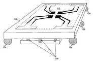
- FIG. 1Ais diagram illustrating a phased array antenna in an integrated circuit package, in accordance with an embodiment of the invention.
- FIG. 1Bis a diagram of an exemplary phased array antenna embedded in and/or on an IC package, in accordance with an embodiment of the invention.
- FIG. 2Ais a diagram illustrating a cross sectional view of a multi-layer IC package with embedded phased array antenna, in accordance with an embodiment of the invention.
- FIG. 2Bis a diagram illustrating a cross sectional view of a multi-layer IC package with embedded phased array antenna and phase shifters, in accordance with an embodiment of the invention.
- FIG. 3is a flow chart illustrating exemplary steps for transmitting signals utilizing a phased array antenna embedded in and/or on an IC package, in accordance with an embodiment of the invention.
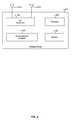
- FIG. 4is a block diagram illustrating an exemplary wireless device, in accordance with an embodiment of the invention.
- a phased array antenna embedded in a multi-layer integrated circuit (IC) packagemay be utilized for transmitting and/or receiving signals.
- the multi-layer packagemay comprise one or more metal layers, insulating material, ferromagnetic, and/or ferrimagnetic materials.
- the antennamay comprise one or more planar transmission lines.
- the phased array antennamay comprise a plurality of antenna elements and each antenna element may comprise an interconnection for communicatively coupling to an associated transmitter and/or receiver, a feeder line, a quarter wavelength transformer, and a radiating portion (e.g., a folded dipole).
- an IC enabled to transmit and/or receive signalsmay be bonded to the multi-layer IC package via one or more solder balls. Accordingly, the IC may communicate a reference signal and/or one or more phase shifted versions of said reference signal to the antenna.
- one or more phase shifters(fabricated, for example, in planar transmission line) may be embedded in the multi-layer IC package and may be controlled via logic, circuitry, and/or code within an IC bonded to the multi-layer IC package.
- FIG. 1Ais diagram illustrating a configurable antenna embedded in and/or on an integrated circuit package, in accordance with an embodiment of the invention.
- ICintegrated circuit
- chipassociated IC
- solder balls 108solder balls
- the IC 106may comprise suitable logic, circuitry, and/or code for performing one or more functions associated with transmitting and/or receiving RF signals.
- the IC 106may comprise all or a portion of the system 420 described with respect to FIG. 4 .
- the IC 106may utilize a phased array antenna embedded in the package 104 for transmitting and/or receiving RF signals.
- the IC 106may comprise suitable logic, circuitry and/or code for driving the antenna 102 with a plurality of phase shifted signals.
- the IC 106may comprise a transmitter and/or a receiver.
- the IC 106may comprise phase shifting circuitry and may be coupled to a separate transmitter and/or receiver (e.g., via one or more traces on a PCB).
- phase shifting elementsmay be fabricated in the package 104 and the package 104 may be utilized as a “stand alone” or “standardized” antenna which may be communicatively coupled to a variety of transmitters and/or receivers.
- the IC 106may be bump-bonded or flip-chip bonded to the multi-layer IC package 104 utilizing the solder balls 108 .
- wire bonds connecting the IC 106 to the multi-layer IC package 104may be eliminated, reducing and/or eliminating uncontrollable stray inductances due to wire bonds.
- the thermal conductance out of the IC 106may be greatly improved utilizing the solder balls 108 and the thermal epoxy 206 ( FIG. 2 ).
- the thermal epoxy 221may be electrically insulating but thermally conductive to allow for thermal energy to be conducted out of the IC 106 to the much larger thermal mass of the multilayer package 104 .
- the solder balls 108may comprise spherical balls of metal to provide electrical, thermal and physical contact between the IC 106 and the multi-layer IC package 104 .
- the ICmay be pressed with enough force to squash the metal spheres somewhat, and may be performed at an elevated temperature to provide suitable electrical resistance and physical bond strength.
- the solder balls 108may also be utilized to provide electrical, thermal and physical contact between the multi-layer IC package 104 and a printed circuit board comprising other parts of the wireless system 420 , described with respect to FIG. 4 .
- the multi-layer IC package 104may comprise one or more layers of metal and/or insulating material (various embodiments may also comprise ferromagnetic and/or ferromagnetic areas and/or layers).
- the package 104may be fabricated in a manner similar to or the same as an IC. Accordingly, the layers may be utilized to realize circuit elements such as resistors, inductors, capacitors, transmission lines, switches, antennas, etc.
- a plurality of elements of the phased array antenna 102may be fabricated in and/or on the package 104 . Accordingly, each of the plurality of antenna elements may transmit and/or receive signals which are phase shifted with respect to other transmitted and/or received signals.
- the phased array antenna 102may comprise a plurality of antenna elements, where each may be a metallic and/or conductive structure capable of coupling RF energy to/from, for example, the transceiver 423 described with respect to FIG. 4 .
- each elementmay be rectangular, circular, and/or another shape.
- One or more of the elementsmay be coupled (by way of one or more vias and/or one or more metal layers) to one or more of the solder balls 108 . In this manner, signals may be conveyed to/from the package 104 .
- four elements corresponding to four phasesare utilized. Accordingly, four phase shifted representations of a reference signal may be transmitted and/or received via the antenna 102 . Details of the exemplary four element phased array antenna are described below with respect to FIG. 1B .
- logic, circuitry, and/or code in the IC 106 and/or in another device coupled to the package 104may transmit and/or receive signals via the phased array antenna 102 .
- the phasing of the signals coupled to the antenna elementsmay be controlled to achieve a desired radiation pattern. In this manner, sensitivity and/or power in a desired direction may be increased over sensitivity and/or power in another direction.
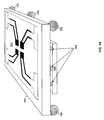
- FIG. 1Bis a diagram of an exemplary phased array antenna embedded in and/or on an IC package, in accordance with an embodiment of the invention.
- the phased array antennamay comprise four antenna elements 150 1 . . . , 150 4 (referred collectively herein as 150 ).
- Each element 150may comprise a folded dipole radiating element 152 1 . . . , 152 4 (referred collectively herein as 152 ), a quarter wavelength transformer 154 1 . . . , 154 4 (referred collectively herein as 154 ), a feeder line 156 1 . . . , 156 4 (referred collectively herein as 156 ), and an interconnection 158 1 . . . , 158 4 (referred collectively herein as 158 ).
- the folded dipole radiating elements 152may each be a metallic and/or conductive material capable of receiving and/or transmitting RF energy via a wireless channel/medium.
- the dipole radiating elements 152 1 - 152 4may be fabricated in, for example, planar transmission line (e.g., microstrip and/or stripline). The physical size of the dipoles may affect which frequency band(s) are best transmitted and/or received.
- Each dipole radiating element 152may transmit a signal which may be phase shifted relative to the signal transmitted by the other dipole radiating elements 152 .
- the quarter wavelength transformers 154may each be a length of, for example, planar transmission line (e.g., microstrip and/or stripline). The length and/or width of quarter wavelength transformer may depend on the frequency of transmission and/or reception as well as the impedance of the dipole radiating elements 152 and the feeder lines 156 . In this regard, the quarter wavelength transformers 154 may impedance match the feeder lines to the folded dipole radiating elements 152 .
- the feeder lines 156may each be a length of, for example, planar or coplanar transmission line utilized to couple RF signals to from the folded dipole radiating elements 152 .
- the interconnections 158may each be a via and/or one or more metal layers in the package 104 which couple the feeder lines 156 to one or more solder balls 108 which couple the package 104 to the IC 106 .
- the phased array antenna 102may be designed to transmit and/or receive signals at or near 60 GHz.
- an exemplary embodimentmay be realized on an approximately 5 mm by 5 mm multi-layer integrated circuit package.
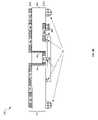
- FIG. 2Ais a diagram illustrating a cross sectional view of a multi-layer IC package with embedded phased array antenna, in accordance with an embodiment of the invention.
- a system 200comprising a IC 106 and a multi-layer IC package 104 .
- the multi-layer IC package 104may comprise an insulating material 203 , and metal layers 202 and 210 . Although only two metal layers are shown, various embodiments of the invention may comprise any number of metal layers.
- the phased array antenna 102may be fabricated in the metal layer 202 and one or more other components such as resistors, capacitors, inductors, transmission lines, phase shifters, etc, may be fabricated in the metal layer 210 .
- the IC 106may be communicatively coupled to the package 104 , and the package 104 to a PCB (not shown), via solder balls 108 .
- One or more surface mount components 208may be mounted to the package 104 .
- Thermal epoxy (or similar material) 206may be pressed between the IC 106 and the package 104 .
- the IC 106may be as described with respect to FIG. 1 .
- the solder balls 108may be as described with respect to FIG. 1 .
- the surface mount device 208may comprise a discrete circuit element such as a resistor, capacitor, inductor, or diode, for example.
- the surface mount device 208may be soldered to the multi-layer IC package 104 to provide electrical contact.
- additional surface mount elements or no surface mount elementsmay be coupled to the package 104 .
- the metal layer 202may comprise a deposited metal layer utilized to delineate the phased array antenna 102 described with respect to FIGS. 1A and 1B .
- the metal layer 202may be deposited as, for example, planar transmission line (e.g. microstrip) in shapes and/or sizes which enable realizing, for example, folded dipole radiating elements 152 , quarter wavelength transformers 154 , and feeder lines 156 .
- the interconnections 158may be realized in the form of one of more vias which may be communicatively coupled the phased array antenna 102 to one or more of the solder balls 108 .
- the metal layer 210may comprise deposited metal layers utilized to delineate discrete components, waveguides, transmission lines, interconnections, etc.
- the component 204 amay be an inductor fabricated in metal layer 210 .
- the transmission line 204 bmay couple the discrete component 208 to a solder ball 108 . In this manner, signals may be conveyed to and/or from the antenna elements 102 in the metal layer 202 .
- the IC 106 and associated package 104may be utilized to transmit and/or receive RF signals.
- the IC 106may be communicatively coupled to the phased array antenna embedded on and/or within the multi-layer IC package 104 .
- the directivity of the phased array antennamay be controlled by altering the phases of signals sent and/or received to/from the phased array antenna.
- a signal to be transmittedmay be modulated onto an RF carrier and four phase-shifted versions of the RF carrier may be generated.
- each signalmay be coupled, via one or more solder balls 108 , to the antenna 102 .
- each signalmay be coupled to a corresponding folded dipole radiating element 152 via an interconnection 158 , feeder line 156 , and quarter wavelength transformer 154 .
- FIG. 2Bis a diagram illustrating a cross sectional view of a multi-layer IC package with embedded configurable antenna and phase shifters, in accordance with an embodiment of the invention.
- a multi-layer IC package 104 with integrated phased array antennasimilar to FIG. 2B .
- FIG. 2Bdiffers from FIG. 2A in that the package 104 in FIG. 2B comprises phase shifter 252 .
- an RF signal coupled from interconnection 158 1 to the IC 106may experience a first phase delay while an RF signal coupled from the interconnection 1583 may experience a second phase delay.
- signals to additional interconnections 158each may experience a different phase shift.
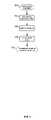
- FIG. 3is a flow chart illustrating exemplary steps for transmitting signals utilizing a phased array antenna embedded in a multi-layer IC package, in accordance with an embodiment of the invention.
- the exemplary stepsmay begin with step 302 when a baseband signal may be ready for transmission. Subsequent to step 302 , the exemplary steps may advance to step 304 .
- the baseband signalmay be modulated onto a carrier signal.
- the baseband signalmay be split into in-phase and quadrature phase signals and modulated onto a pair of phase quadrature carrier signals.
- various embodiments of the inventionmay utilize carriers at or near 60 GHz.
- the modulated signalsmay then be combined to generate an RF signal.
- the exemplary stepsmay advance to step 306 .
- the RF signal generated in step 304may be split into a plurality of phases.
- the signalmay be split into four phases.
- the phasing of the signalsmay be utilized to control the directivity of the phased array antenna.
- the exemplary stepsmay advance to step 308 .
- the RF signalsmay be amplified.
- a power amplifiermay amplify the signals such that sufficient signal strength may be radiated via the phased array antenna.
- the exemplary stepsmay advance to step 310 .
- the amplified signalsmay be conveyed to the phased array antenna for transmission.
- a number of phasesmay be conveyed to a corresponding number of radiating elements.
- Steps similar to those described with respect to FIG. 3may also be applied to receiving signals via a phased array antenna integrated into an IC package.
- FIG. 4is a block diagram illustrating an exemplary wireless device, in accordance with an embodiment of the invention.
- a wireless device 420may comprise an RF receiver 423 a , an RF transmitter 423 b , a digital baseband processor 429 , a processor 425 , and a memory 427 .
- a receive antenna 421 amay be communicatively coupled to the RF receiver 423 a .
- a transmit antenna 421 bmay be communicatively coupled to the RF transmitter 423 b .
- the wireless device 420may be operated in a system, such as the cellular network and/or digital video broadcast network, for example.
- the antennas 421 a and 421 bmay be phased array antennas, similar to or the same as, the antenna 102 described with respect to FIG. 1A .
- the directivity of the antennasmay be controlled by controlling the phase(s) of signals coupled to the antenna.
- the RF receiver 423 amay comprise suitable logic, circuitry, and/or code that may enable processing of received RF signals.
- the RF receiver 423 amay enable receiving RF signals in a plurality of frequency bands.
- the RF receiver 423 amay enable receiving signals in extremely high frequency (e.g., 60 GHz) bands.
- the receiver 423 amay be enabled to receive, filter, amplify, down-convert, and/or perform analog to digital conversion.
- the RF receiver 423 amay down convert a received RF signal.
- the RF receiver 423 amay perform direct down conversion of the received RF signal to a baseband or may convert the received RF signal to an intermediate frequency (IF).
- IFintermediate frequency
- the receiver 423 amay perform quadrature down-conversion where in-phase components and quadrature phase components may be processed in parallel.
- the receiver 423 amay be enabled to receive signals via the antenna 421 a , which may be a phased array antenna embedded in and/or on an integrated circuit package, as described with respect to FIGS. 1A , 1 B, 2 A, and 2 B.
- the wireless device 420may comprise a plurality of the receivers 423 a and may thus support multiple frequency bands and or simultaneous reception of signals in the same frequency band.
- the digital baseband processor 429may comprise suitable logic, circuitry, and/or code that may enable processing and/or handling of baseband signals.
- the digital baseband processor 429may process or handle signals received from the RF receiver 423 a and/or signals to be transferred to the RF transmitter 423 b , when the RF transmitter 423 b is present, for transmission to the network.
- the digital baseband processor 429may also provide control and/or feedback information to the RF receiver 423 a and to the RF transmitter 423 b based on information from the processed signals.
- the baseband processor 429may provide one or more control signals for configuring phase shifting of received and/or transmitted RF signals.
- the phase shift applied to RF signalsmay enable controlling the directivity of the phased array antenna.
- the digital baseband processor 429may communicate information and/or data from the processed signals to the processor 425 and/or to the memory 427 . Moreover, the digital baseband processor 429 may receive information from the processor 425 and/or to the memory 427 , which may be processed and transferred to the RF transmitter 423 b for transmission to the network.
- the RF transmitter 423 bmay comprise suitable logic, circuitry, and/or code that may enable processing of RF signals for transmission.
- the transmitter 423 bmay be enabled to transmit signals via the antenna 421 b , which may be a phased array antenna fabricated in an integrated circuit package as described with respect to FIGS. 1A , 1 B, 2 A, and 2 B.
- the RF transmitter 423 bmay enable transmission of RF signals in a plurality of frequency bands.
- the RF transmitter 423 bmay enable transmitting signals in extremely high frequency (e.g., 60 GHz) bands.
- Each frequency band supported by the RF transmitter 423 bmay have a corresponding front-end circuit for handling amplification and up conversion operations, for example.
- the RF transmitter 423 bmay be referred to as a multi-band transmitter when it supports more than one frequency band.
- the wireless device 420may comprise more than one RF transmitter 423 b , wherein each of the RF transmitter 423 b may be a single-band or a multi-band transmitter.
- the RF transmitter 423 bmay perform direct up conversion of the baseband signal to an RF signal. In some instances, the RF transmitter 423 b may enable digital-to-analog conversion of the baseband signal components received from the digital baseband processor 429 before up conversion. In other instances, the RF transmitter 423 b may receive baseband signal components in analog form.
- the processor 425may comprise suitable logic, circuitry, and/or code that may enable control and/or data processing operations for the wireless device 420 .
- the processor 425may be utilized to control at least a portion of the RF receiver 423 a , the RF transmitter 423 b , the digital baseband processor 429 , and/or the memory 427 .
- the processor 425may generate at least one signal for controlling operations within the wireless device 420 .
- the baseband processor 429may provide one or more control signals for controlling a phase of signals transmitted and/or received via the phased array antennas 421 a and 421 b .
- the processor 425may also enable executing of applications that may be utilized by the wireless device 420 .
- the processor 425may execute applications that may enable displaying and/or interacting with content received via cellular transmission signals in the wireless device 420 .
- the memory 427may comprise suitable logic, circuitry, and/or code that may enable storage of data and/or other information utilized by the wireless device 420 .
- the memory 427may be utilized for storing processed data generated by the digital baseband processor 429 and/or the processor 425 .
- the memory 427may also be utilized to store information, such as configuration information, that may be utilized to control the operation of at least one block in the wireless device 420 .
- the memory 427may comprise information necessary to control phase of signals transmitted and/or received via the antenna(s) 421 a and 421 b .
- the memorymay store control and/or configuration information for configuring one or more phase shifters.
- a phased array antenna(e.g., 102 ) embedded in a multi-layer integrated circuit (IC) package (e.g., 104 ) may be utilized for transmitting and/or receiving signals.
- the multi-layer packagemay comprise one or more metal layers (e.g., 202 and 210 ), insulating material (e.g., 203 ), ferromagnetic, and/or ferrimagnetic material.
- the antennamay comprise one or more planar transmission lines.
- the phased array antennamay comprise a plurality of antenna elements (e.g., 150 ) and each antenna element may comprise an interconnection (e.g., 158 ) for communicatively coupling to an associated transmitter and/or receiver, a feeder line (e.g., 156 ), a quarter wavelength transformer (e.g., 154 ), and a radiating portion (e.g. folded dipole 152 ).
- an ICe.g., 106
- enabled to transmit and/or receive signalsmay be bonded to the multi-layer IC package via one or more solder balls (e.g., 211 ).
- the ICmay communicate a reference signal and/or one or more phase shifted versions of said reference signal to the antenna.
- one or more phase shifterse.g., 252
- Another embodiment of the inventionmay provide a machine-readable storage, having stored thereon, a computer program having at least one code section executable by a machine, thereby causing the machine to perform the steps as described herein for a phased array antenna in an integrated circuit package.
- the present inventionmay be realized in hardware, software, or a combination of hardware and software.
- the present inventionmay be realized in a centralized fashion in at least one computer system, or in a distributed fashion where different elements are spread across several interconnected computer systems. Any kind of computer system or other apparatus adapted for carrying out the methods described herein is suited.
- a typical combination of hardware and softwaremay be a general-purpose computer system with a computer program that, when being loaded and executed, controls the computer system such that it carries out the methods described herein.
- the present inventionmay also be embedded in a computer program product, which comprises all the features enabling the implementation of the methods described herein, and which when loaded in a computer system is able to carry out these methods.
- Computer program in the present contextmeans any expression, in any language, code or notation, of a set of instructions intended to cause a system having an information processing capability to perform a particular function either directly or after either or both of the following: a) conversion to another language, code or notation; b) reproduction in a different material form.
Landscapes
- Engineering & Computer Science (AREA)
- Physics & Mathematics (AREA)
- Condensed Matter Physics & Semiconductors (AREA)
- General Physics & Mathematics (AREA)
- Computer Hardware Design (AREA)
- Microelectronics & Electronic Packaging (AREA)
- Power Engineering (AREA)
- Manufacturing & Machinery (AREA)
- Computer Networks & Wireless Communication (AREA)
- Signal Processing (AREA)
- Variable-Direction Aerials And Aerial Arrays (AREA)
- Details Of Aerials (AREA)
Abstract
Description
Claims (20)
Priority Applications (8)
| Application Number | Priority Date | Filing Date | Title |
|---|---|---|---|
| US11/954,822US7880677B2 (en) | 2007-12-12 | 2007-12-12 | Method and system for a phased array antenna embedded in an integrated circuit package |
| EP08020760AEP2071663B1 (en) | 2007-12-12 | 2008-11-28 | Phased array antenna embedded in an integrated circuit package |
| CN2008101870406ACN101459168B (en) | 2007-12-12 | 2008-12-12 | Method and system for a phased array antenna embedded in an integrated circuit package |
| KR1020080126760AKR101150249B1 (en) | 2007-12-12 | 2008-12-12 | Method and system for a phased array antenna embedded in an integrated circuit package |
| TW097148608ATWI414108B (en) | 2007-12-12 | 2008-12-12 | Method and system for a phased array antenna embedded in an integrated circuit package |
| HK09111244.2AHK1138106B (en) | 2007-12-12 | 2009-12-01 | Method and system for signal processing |
| US13/019,007US8199060B2 (en) | 2007-12-12 | 2011-02-01 | Method and system for a phased array antenna embedded in an integrated circuit package |
| US13/491,310US8497805B2 (en) | 2007-12-12 | 2012-06-07 | IC package with embedded phased array antenna |
Applications Claiming Priority (1)
| Application Number | Priority Date | Filing Date | Title |
|---|---|---|---|
| US11/954,822US7880677B2 (en) | 2007-12-12 | 2007-12-12 | Method and system for a phased array antenna embedded in an integrated circuit package |
Related Child Applications (1)
| Application Number | Title | Priority Date | Filing Date |
|---|---|---|---|
| US13/019,007ContinuationUS8199060B2 (en) | 2007-12-12 | 2011-02-01 | Method and system for a phased array antenna embedded in an integrated circuit package |
Publications (2)
| Publication Number | Publication Date |
|---|---|
| US20090153428A1 US20090153428A1 (en) | 2009-06-18 |
| US7880677B2true US7880677B2 (en) | 2011-02-01 |
Family
ID=40383857
Family Applications (3)
| Application Number | Title | Priority Date | Filing Date |
|---|---|---|---|
| US11/954,822Active2029-04-03US7880677B2 (en) | 2007-12-12 | 2007-12-12 | Method and system for a phased array antenna embedded in an integrated circuit package |
| US13/019,007Expired - Fee RelatedUS8199060B2 (en) | 2007-12-12 | 2011-02-01 | Method and system for a phased array antenna embedded in an integrated circuit package |
| US13/491,310Expired - Fee RelatedUS8497805B2 (en) | 2007-12-12 | 2012-06-07 | IC package with embedded phased array antenna |
Family Applications After (2)
| Application Number | Title | Priority Date | Filing Date |
|---|---|---|---|
| US13/019,007Expired - Fee RelatedUS8199060B2 (en) | 2007-12-12 | 2011-02-01 | Method and system for a phased array antenna embedded in an integrated circuit package |
| US13/491,310Expired - Fee RelatedUS8497805B2 (en) | 2007-12-12 | 2012-06-07 | IC package with embedded phased array antenna |
Country Status (5)
| Country | Link |
|---|---|
| US (3) | US7880677B2 (en) |
| EP (1) | EP2071663B1 (en) |
| KR (1) | KR101150249B1 (en) |
| CN (1) | CN101459168B (en) |
| TW (1) | TWI414108B (en) |
Cited By (62)
| Publication number | Priority date | Publication date | Assignee | Title |
|---|---|---|---|---|
| US20090243779A1 (en)* | 2008-03-27 | 2009-10-01 | Ahmadreza Rofougaran | Method and system for reconfigurable devices for multi-frequency coexistence |
| US20090243767A1 (en)* | 2008-03-28 | 2009-10-01 | Ahmadreza Rofougaran | Method and system for configuring a transformer embedded in a multi-layer integrated circuit (ic) package |
| US8106829B2 (en) | 2007-12-12 | 2012-01-31 | Broadcom Corporation | Method and system for an integrated antenna and antenna management |
| US20130141284A1 (en)* | 2011-12-05 | 2013-06-06 | Samsung Electro-Mechanics Co., Ltd. | Rfic antenna package for millimeter band and rf module including the same |
| US8502735B1 (en)* | 2009-11-18 | 2013-08-06 | Ball Aerospace & Technologies Corp. | Antenna system with integrated circuit package integrated radiators |
| US8532492B2 (en) | 2009-02-03 | 2013-09-10 | Corning Cable Systems Llc | Optical fiber-based distributed antenna systems, components, and related methods for calibration thereof |
| US8639121B2 (en) | 2009-11-13 | 2014-01-28 | Corning Cable Systems Llc | Radio-over-fiber (RoF) system for protocol-independent wired and/or wireless communication |
| US8644844B2 (en) | 2007-12-20 | 2014-02-04 | Corning Mobileaccess Ltd. | Extending outdoor location based services and applications into enclosed areas |
| US8831428B2 (en) | 2010-02-15 | 2014-09-09 | Corning Optical Communications LLC | Dynamic cell bonding (DCB) for radio-over-fiber (RoF)-based networks and communication systems and related methods |
| US8873585B2 (en) | 2006-12-19 | 2014-10-28 | Corning Optical Communications Wireless Ltd | Distributed antenna system for MIMO technologies |
| US8983301B2 (en) | 2010-03-31 | 2015-03-17 | Corning Optical Communications LLC | Localization services in optical fiber-based distributed communications components and systems, and related methods |
| US9059519B2 (en) | 2012-05-30 | 2015-06-16 | National Sun Yat-Sen University | MIMO antenna device, antenna and antenna package |
| US9158864B2 (en) | 2012-12-21 | 2015-10-13 | Corning Optical Communications Wireless Ltd | Systems, methods, and devices for documenting a location of installed equipment |
| US9178635B2 (en) | 2014-01-03 | 2015-11-03 | Corning Optical Communications Wireless Ltd | Separation of communication signal sub-bands in distributed antenna systems (DASs) to reduce interference |
| US9185674B2 (en) | 2010-08-09 | 2015-11-10 | Corning Cable Systems Llc | Apparatuses, systems, and methods for determining location of a mobile device(s) in a distributed antenna system(s) |
| US9184843B2 (en) | 2011-04-29 | 2015-11-10 | Corning Optical Communications LLC | Determining propagation delay of communications in distributed antenna systems, and related components, systems, and methods |
| US9219546B2 (en) | 2011-12-12 | 2015-12-22 | Corning Optical Communications LLC | Extremely high frequency (EHF) distributed antenna systems, and related components and methods |
| US9240835B2 (en) | 2011-04-29 | 2016-01-19 | Corning Optical Communications LLC | Systems, methods, and devices for increasing radio frequency (RF) power in distributed antenna systems |
| US9247543B2 (en) | 2013-07-23 | 2016-01-26 | Corning Optical Communications Wireless Ltd | Monitoring non-supported wireless spectrum within coverage areas of distributed antenna systems (DASs) |
| US9258052B2 (en) | 2012-03-30 | 2016-02-09 | Corning Optical Communications LLC | Reducing location-dependent interference in distributed antenna systems operating in multiple-input, multiple-output (MIMO) configuration, and related components, systems, and methods |
| US9323020B2 (en) | 2008-10-09 | 2016-04-26 | Corning Cable Systems (Shanghai) Co. Ltd | Fiber optic terminal having adapter panel supporting both input and output fibers from an optical splitter |
| US9357551B2 (en) | 2014-05-30 | 2016-05-31 | Corning Optical Communications Wireless Ltd | Systems and methods for simultaneous sampling of serial digital data streams from multiple analog-to-digital converters (ADCS), including in distributed antenna systems |
| US9385810B2 (en) | 2013-09-30 | 2016-07-05 | Corning Optical Communications Wireless Ltd | Connection mapping in distributed communication systems |
| US9420542B2 (en) | 2014-09-25 | 2016-08-16 | Corning Optical Communications Wireless Ltd | System-wide uplink band gain control in a distributed antenna system (DAS), based on per band gain control of remote uplink paths in remote units |
| US9455784B2 (en) | 2012-10-31 | 2016-09-27 | Corning Optical Communications Wireless Ltd | Deployable wireless infrastructures and methods of deploying wireless infrastructures |
| US9525472B2 (en) | 2014-07-30 | 2016-12-20 | Corning Incorporated | Reducing location-dependent destructive interference in distributed antenna systems (DASS) operating in multiple-input, multiple-output (MIMO) configuration, and related components, systems, and methods |
| US9531452B2 (en) | 2012-11-29 | 2016-12-27 | Corning Optical Communications LLC | Hybrid intra-cell / inter-cell remote unit antenna bonding in multiple-input, multiple-output (MIMO) distributed antenna systems (DASs) |
| US9547145B2 (en) | 2010-10-19 | 2017-01-17 | Corning Optical Communications LLC | Local convergence point for multiple dwelling unit fiber optic distribution network |
| US9590733B2 (en) | 2009-07-24 | 2017-03-07 | Corning Optical Communications LLC | Location tracking using fiber optic array cables and related systems and methods |
| US9602210B2 (en) | 2014-09-24 | 2017-03-21 | Corning Optical Communications Wireless Ltd | Flexible head-end chassis supporting automatic identification and interconnection of radio interface modules and optical interface modules in an optical fiber-based distributed antenna system (DAS) |
| US9621293B2 (en) | 2012-08-07 | 2017-04-11 | Corning Optical Communications Wireless Ltd | Distribution of time-division multiplexed (TDM) management services in a distributed antenna system, and related components, systems, and methods |
| US9648580B1 (en) | 2016-03-23 | 2017-05-09 | Corning Optical Communications Wireless Ltd | Identifying remote units in a wireless distribution system (WDS) based on assigned unique temporal delay patterns |
| US9647758B2 (en) | 2012-11-30 | 2017-05-09 | Corning Optical Communications Wireless Ltd | Cabling connectivity monitoring and verification |
| US9661781B2 (en) | 2013-07-31 | 2017-05-23 | Corning Optical Communications Wireless Ltd | Remote units for distributed communication systems and related installation methods and apparatuses |
| US9673904B2 (en) | 2009-02-03 | 2017-06-06 | Corning Optical Communications LLC | Optical fiber-based distributed antenna systems, components, and related methods for calibration thereof |
| US9681313B2 (en) | 2015-04-15 | 2017-06-13 | Corning Optical Communications Wireless Ltd | Optimizing remote antenna unit performance using an alternative data channel |
| US9715157B2 (en) | 2013-06-12 | 2017-07-25 | Corning Optical Communications Wireless Ltd | Voltage controlled optical directional coupler |
| US9730228B2 (en) | 2014-08-29 | 2017-08-08 | Corning Optical Communications Wireless Ltd | Individualized gain control of remote uplink band paths in a remote unit in a distributed antenna system (DAS), based on combined uplink power level in the remote unit |
| US9729267B2 (en) | 2014-12-11 | 2017-08-08 | Corning Optical Communications Wireless Ltd | Multiplexing two separate optical links with the same wavelength using asymmetric combining and splitting |
| US9775123B2 (en) | 2014-03-28 | 2017-09-26 | Corning Optical Communications Wireless Ltd. | Individualized gain control of uplink paths in remote units in a distributed antenna system (DAS) based on individual remote unit contribution to combined uplink power |
| US9781553B2 (en) | 2012-04-24 | 2017-10-03 | Corning Optical Communications LLC | Location based services in a distributed communication system, and related components and methods |
| US9807700B2 (en) | 2015-02-19 | 2017-10-31 | Corning Optical Communications Wireless Ltd | Offsetting unwanted downlink interference signals in an uplink path in a distributed antenna system (DAS) |
| US9948349B2 (en) | 2015-07-17 | 2018-04-17 | Corning Optical Communications Wireless Ltd | IOT automation and data collection system |
| US9960792B2 (en) | 2013-03-15 | 2018-05-01 | Keyssa, Inc. | Extremely high frequency communication chip |
| US9974074B2 (en) | 2013-06-12 | 2018-05-15 | Corning Optical Communications Wireless Ltd | Time-division duplexing (TDD) in distributed communications systems, including distributed antenna systems (DASs) |
| US10027382B2 (en) | 2012-09-14 | 2018-07-17 | Keyssa, Inc. | Wireless connections with virtual hysteresis |
| US10033439B2 (en) | 2012-12-17 | 2018-07-24 | Keyssa, Inc. | Modular electronics |
| TWI631834B (en)* | 2011-03-24 | 2018-08-01 | 美商奇沙公司 | Integrated circuit with electromagnetic communication |
| US10069183B2 (en) | 2012-08-10 | 2018-09-04 | Keyssa, Inc. | Dielectric coupling systems for EHF communications |
| US10110307B2 (en) | 2012-03-02 | 2018-10-23 | Corning Optical Communications LLC | Optical network units (ONUs) for high bandwidth connectivity, and related components and methods |
| US10128951B2 (en) | 2009-02-03 | 2018-11-13 | Corning Optical Communications LLC | Optical fiber-based distributed antenna systems, components, and related methods for monitoring and configuring thereof |
| US10136200B2 (en) | 2012-04-25 | 2018-11-20 | Corning Optical Communications LLC | Distributed antenna system architectures |
| US10236924B2 (en) | 2016-03-31 | 2019-03-19 | Corning Optical Communications Wireless Ltd | Reducing out-of-channel noise in a wireless distribution system (WDS) |
| US10243621B2 (en) | 2008-12-23 | 2019-03-26 | Keyssa, Inc. | Tightly-coupled near-field communication-link connector-replacement chips |
| US20200044321A1 (en)* | 2018-08-06 | 2020-02-06 | Commscope Technologies Llc | Multi-layer phase shifter driving device and related remote electronic tilt systems and antennas |
| US10560214B2 (en) | 2015-09-28 | 2020-02-11 | Corning Optical Communications LLC | Downlink and uplink communication path switching in a time-division duplex (TDD) distributed antenna system (DAS) |
| US10602363B2 (en) | 2013-03-15 | 2020-03-24 | Keyssa, Inc. | EHF secure communication device |
| US10790576B2 (en) | 2015-12-14 | 2020-09-29 | Commscope Technologies Llc | Multi-band base station antennas having multi-layer feed boards |
| WO2022098342A1 (en)* | 2020-11-03 | 2022-05-12 | Intel Corporation | Distributed radiohead system |
| US11626373B2 (en) | 2020-06-17 | 2023-04-11 | Samsung Electronics Co., Ltd. | Semiconductor packages including antenna pattern |
| US11671914B2 (en) | 2010-10-13 | 2023-06-06 | Corning Optical Communications LLC | Power management for remote antenna units in distributed antenna systems |
| US12212045B2 (en) | 2020-07-13 | 2025-01-28 | Samsung Electronics Co., Ltd. | Antenna and electronic device comprising same |
Families Citing this family (87)
| Publication number | Priority date | Publication date | Assignee | Title |
|---|---|---|---|---|
| US7675465B2 (en) | 2007-05-22 | 2010-03-09 | Sibeam, Inc. | Surface mountable integrated circuit packaging scheme |
| US8160498B2 (en)* | 2007-12-12 | 2012-04-17 | Broadcom Corporation | Method and system for portable data storage with integrated 60 GHz radio |
| US8270912B2 (en)* | 2007-12-12 | 2012-09-18 | Broadcom Corporation | Method and system for a transformer in an integrated circuit package |
| US8064936B2 (en)* | 2008-02-28 | 2011-11-22 | Broadcom Corporation | Method and system for a multistandard proxy |
| US8072287B2 (en)* | 2008-03-27 | 2011-12-06 | Broadcom Corporation | Method and system for configurable differential or single-ended signaling in an integrated circuit |
| EP2178119B1 (en)* | 2008-10-20 | 2018-06-20 | QUALCOMM Incorporated | Surface mountable integrated circuit package |
| EP2347440A1 (en)* | 2008-11-19 | 2011-07-27 | Nxp B.V. | Millimetre-wave radio antenna module |
| US8660500B2 (en) | 2009-06-09 | 2014-02-25 | Broadcom Corporation | Method and system for a voltage-controlled oscillator with a leaky wave antenna |
| US8588686B2 (en)* | 2009-06-09 | 2013-11-19 | Broadcom Corporation | Method and system for remote power distribution and networking for passive devices |
| WO2011025241A2 (en)* | 2009-08-26 | 2011-03-03 | 연세대학교 산학협력단 | Bonding wire antenna communication module |
| EP2494655B1 (en)* | 2009-10-29 | 2018-07-18 | Technische Universität Dresden | Antenna arrangement for signal transmission |
| US9401745B1 (en)* | 2009-12-11 | 2016-07-26 | Micron Technology, Inc. | Wireless communication link using near field coupling |
| WO2012170865A2 (en) | 2011-06-09 | 2012-12-13 | Lgc Wireless, Llc | Antenna module having integrated radio frequency circuitry |
| US10403511B2 (en)* | 2013-01-14 | 2019-09-03 | Intel Corporation | Backside redistribution layer patch antenna |
| US9917372B2 (en) | 2014-06-13 | 2018-03-13 | Nxp Usa, Inc. | Integrated circuit package with radio frequency coupling arrangement |
| US9620841B2 (en) | 2014-06-13 | 2017-04-11 | Nxp Usa, Inc. | Radio frequency coupling structure |
| US10103447B2 (en) | 2014-06-13 | 2018-10-16 | Nxp Usa, Inc. | Integrated circuit package with radio frequency coupling structure |
| US9865600B2 (en) | 2014-06-18 | 2018-01-09 | X-Celeprint Limited | Printed capacitors |
| TWI652796B (en)* | 2014-06-18 | 2019-03-01 | 愛爾蘭商艾克斯瑟樂普林特有限公司 | Multilayer printed capacitor |
| US10225925B2 (en) | 2014-08-29 | 2019-03-05 | Nxp Usa, Inc. | Radio frequency coupling and transition structure |
| US9887449B2 (en) | 2014-08-29 | 2018-02-06 | Nxp Usa, Inc. | Radio frequency coupling structure and a method of manufacturing thereof |
| US9444135B2 (en)* | 2014-09-19 | 2016-09-13 | Freescale Semiconductor, Inc. | Integrated circuit package |
| US10317512B2 (en)* | 2014-12-23 | 2019-06-11 | Infineon Technologies Ag | RF system with an RFIC and antenna system |
| US10725150B2 (en) | 2014-12-23 | 2020-07-28 | Infineon Technologies Ag | System and method for radar |
| US9667290B2 (en) | 2015-04-17 | 2017-05-30 | Apple Inc. | Electronic device with millimeter wave antennas |
| US10452148B2 (en) | 2016-01-19 | 2019-10-22 | Infineon Technologies Ag | Wearable consumer device |
| US10622700B2 (en) | 2016-05-18 | 2020-04-14 | X-Celeprint Limited | Antenna with micro-transfer-printed circuit element |
| US10181653B2 (en) | 2016-07-21 | 2019-01-15 | Infineon Technologies Ag | Radio frequency system for wearable device |
| US10218407B2 (en) | 2016-08-08 | 2019-02-26 | Infineon Technologies Ag | Radio frequency system and method for wearable device |
| WO2018081146A1 (en)* | 2016-10-24 | 2018-05-03 | Anokiwave, Inc. | Beamforming integrated circuit with rf grounded material ring and integral thermal mass |
| US10466772B2 (en) | 2017-01-09 | 2019-11-05 | Infineon Technologies Ag | System and method of gesture detection for a remote device |
| US10505255B2 (en) | 2017-01-30 | 2019-12-10 | Infineon Technologies Ag | Radio frequency device packages and methods of formation thereof |
| US10056922B1 (en)* | 2017-06-14 | 2018-08-21 | Infineon Technologies Ag | Radio frequency device modules and methods of formation thereof |
| US10602548B2 (en) | 2017-06-22 | 2020-03-24 | Infineon Technologies Ag | System and method for gesture sensing |
| US10944180B2 (en) | 2017-07-10 | 2021-03-09 | Viasat, Inc. | Phased array antenna |
| US11394103B2 (en)* | 2017-07-18 | 2022-07-19 | Samsung Electro-Mechanics Co., Ltd. | Antenna module and manufacturing method thereof |
| CN107332573B (en)* | 2017-07-25 | 2021-04-13 | Oppo广东移动通信有限公司 | A radio frequency circuit, antenna device and electronic equipment |
| TWI685144B (en)* | 2017-11-30 | 2020-02-11 | 太盟光電科技股份有限公司 | Surface-mount signal transceiver module with multi-signal feed-in |
| CN108109984A (en)* | 2017-12-07 | 2018-06-01 | 中芯长电半导体(江阴)有限公司 | Semiconductor package and preparation method thereof |
| US10746625B2 (en) | 2017-12-22 | 2020-08-18 | Infineon Technologies Ag | System and method of monitoring a structural object using a millimeter-wave radar sensor |
| US10312569B1 (en) | 2018-01-05 | 2019-06-04 | Cirocomm Technology Corp. | Surface-mounted signal transceiver module with multi-signal feed-in |
| US11346936B2 (en) | 2018-01-16 | 2022-05-31 | Infineon Technologies Ag | System and method for vital signal sensing using a millimeter-wave radar sensor |
| US11278241B2 (en) | 2018-01-16 | 2022-03-22 | Infineon Technologies Ag | System and method for vital signal sensing using a millimeter-wave radar sensor |
| US10795012B2 (en) | 2018-01-22 | 2020-10-06 | Infineon Technologies Ag | System and method for human behavior modelling and power control using a millimeter-wave radar sensor |
| US10576328B2 (en) | 2018-02-06 | 2020-03-03 | Infineon Technologies Ag | System and method for contactless sensing on a treadmill |
| US10705198B2 (en) | 2018-03-27 | 2020-07-07 | Infineon Technologies Ag | System and method of monitoring an air flow using a millimeter-wave radar sensor |
| US10775482B2 (en) | 2018-04-11 | 2020-09-15 | Infineon Technologies Ag | Human detection and identification in a setting using millimeter-wave radar |
| US10761187B2 (en) | 2018-04-11 | 2020-09-01 | Infineon Technologies Ag | Liquid detection using millimeter-wave radar sensor |
| US11189905B2 (en) | 2018-04-13 | 2021-11-30 | International Business Machines Corporation | Integrated antenna array packaging structures and methods |
| US10794841B2 (en) | 2018-05-07 | 2020-10-06 | Infineon Technologies Ag | Composite material structure monitoring system |
| US10553551B2 (en)* | 2018-05-08 | 2020-02-04 | Speedlink Technology Inc. | Impedance compensation of flip chip connection for RF communications |
| US10399393B1 (en) | 2018-05-29 | 2019-09-03 | Infineon Technologies Ag | Radar sensor system for tire monitoring |
| US10903567B2 (en) | 2018-06-04 | 2021-01-26 | Infineon Technologies Ag | Calibrating a phased array system |
| US11416077B2 (en) | 2018-07-19 | 2022-08-16 | Infineon Technologies Ag | Gesture detection system and method using a radar sensor |
| US10928501B2 (en) | 2018-08-28 | 2021-02-23 | Infineon Technologies Ag | Target detection in rainfall and snowfall conditions using mmWave radar |
| US11183772B2 (en) | 2018-09-13 | 2021-11-23 | Infineon Technologies Ag | Embedded downlight and radar system |
| US11125869B2 (en) | 2018-10-16 | 2021-09-21 | Infineon Technologies Ag | Estimating angle of human target using mmWave radar |
| US11397239B2 (en) | 2018-10-24 | 2022-07-26 | Infineon Technologies Ag | Radar sensor FSM low power mode |
| US11360185B2 (en) | 2018-10-24 | 2022-06-14 | Infineon Technologies Ag | Phase coded FMCW radar |
| EP3654053A1 (en) | 2018-11-14 | 2020-05-20 | Infineon Technologies AG | Package with acoustic sensing device(s) and millimeter wave sensing elements |
| US10862192B2 (en)* | 2018-12-18 | 2020-12-08 | Texas Instruments Incorporated | Non-contact test solution for antenna-on-package (AOP) devices using near-field coupled RF loopback paths |
| US11087115B2 (en) | 2019-01-22 | 2021-08-10 | Infineon Technologies Ag | User authentication using mm-Wave sensor for automotive radar systems |
| US11355838B2 (en) | 2019-03-18 | 2022-06-07 | Infineon Technologies Ag | Integration of EBG structures (single layer/multi-layer) for isolation enhancement in multilayer embedded packaging technology at mmWave |
| US11126885B2 (en) | 2019-03-21 | 2021-09-21 | Infineon Technologies Ag | Character recognition in air-writing based on network of radars |
| US11454696B2 (en) | 2019-04-05 | 2022-09-27 | Infineon Technologies Ag | FMCW radar integration with communication system |
| US11327167B2 (en) | 2019-09-13 | 2022-05-10 | Infineon Technologies Ag | Human target tracking system and method |
| US11774592B2 (en) | 2019-09-18 | 2023-10-03 | Infineon Technologies Ag | Multimode communication and radar system resource allocation |
| WO2021079361A1 (en)* | 2019-10-21 | 2021-04-29 | Rfisee Ltd | Antenna-on-package array |
| US11435443B2 (en) | 2019-10-22 | 2022-09-06 | Infineon Technologies Ag | Integration of tracking with classifier in mmwave radar |
| US11808883B2 (en) | 2020-01-31 | 2023-11-07 | Infineon Technologies Ag | Synchronization of multiple mmWave devices |
| US11614516B2 (en) | 2020-02-19 | 2023-03-28 | Infineon Technologies Ag | Radar vital signal tracking using a Kalman filter |
| US11585891B2 (en) | 2020-04-20 | 2023-02-21 | Infineon Technologies Ag | Radar-based vital sign estimation |
| US11567185B2 (en) | 2020-05-05 | 2023-01-31 | Infineon Technologies Ag | Radar-based target tracking using motion detection |
| US11774553B2 (en) | 2020-06-18 | 2023-10-03 | Infineon Technologies Ag | Parametric CNN for radar processing |
| US11704917B2 (en) | 2020-07-09 | 2023-07-18 | Infineon Technologies Ag | Multi-sensor analysis of food |
| US11614511B2 (en) | 2020-09-17 | 2023-03-28 | Infineon Technologies Ag | Radar interference mitigation |
| US11719787B2 (en) | 2020-10-30 | 2023-08-08 | Infineon Technologies Ag | Radar-based target set generation |
| US11719805B2 (en) | 2020-11-18 | 2023-08-08 | Infineon Technologies Ag | Radar based tracker using empirical mode decomposition (EMD) and invariant feature transform (IFT) |
| US12189021B2 (en) | 2021-02-18 | 2025-01-07 | Infineon Technologies Ag | Radar-based target tracker |
| US11662430B2 (en) | 2021-03-17 | 2023-05-30 | Infineon Technologies Ag | MmWave radar testing |
| KR20220141013A (en)* | 2021-04-12 | 2022-10-19 | 삼성전자주식회사 | Antenna structure including phase shifter and electronic device including same |
| US11950895B2 (en) | 2021-05-28 | 2024-04-09 | Infineon Technologies Ag | Radar sensor system for blood pressure sensing, and associated method |
| US12307761B2 (en) | 2021-08-06 | 2025-05-20 | Infineon Technologies Ag | Scene-adaptive radar |
| US12405351B2 (en) | 2022-03-25 | 2025-09-02 | Infineon Technologies Ag | Adaptive Tx-Rx crosstalk cancellation for radar systems |
| US12399254B2 (en) | 2022-06-07 | 2025-08-26 | Infineon Technologies Ag | Radar-based single target vital sensing |
| US12399271B2 (en) | 2022-07-20 | 2025-08-26 | Infineon Technologies Ag | Radar-based target tracker |
| US12254670B2 (en) | 2022-07-29 | 2025-03-18 | Infineon Technologies Ag | Radar-based activity classification |
Citations (20)
| Publication number | Priority date | Publication date | Assignee | Title |
|---|---|---|---|---|
| WO1996021255A1 (en) | 1995-01-06 | 1996-07-11 | Georgia Tech Research Corporation | Curtain antenna |
| US6060433A (en) | 1998-01-26 | 2000-05-09 | Nz Applied Technologies Corporation | Method of making a microwave device having a polycrystalline ferrite substrate |
| EP1146592A1 (en) | 1998-12-24 | 2001-10-17 | NEC Corporation | Phased array antenna and its manufacturing method |
| US20040041732A1 (en) | 2001-10-03 | 2004-03-04 | Masayoshi Aikawa | Multielement planar antenna |
| US20040150554A1 (en) | 2003-02-05 | 2004-08-05 | Stenger Peter A. | Low profile active electronically scanned antenna (AESA) for Ka-band radar systems |
| US20040222506A1 (en) | 2002-10-15 | 2004-11-11 | Silicon Laboratories, Inc. | Integrated circuit package configuration incorporating shielded circuit element structure |
| US20050012675A1 (en)* | 2001-12-04 | 2005-01-20 | Kazuyuki Sakiyama | Antenna and apparatus comprising this antenna |
| KR20050065395A (en) | 2003-12-24 | 2005-06-29 | 엔이씨 가꼬오부쯔 디바이스 가부시끼가이샤 | High frequency module and method of manufacturing the same |
| CN1716695A (en) | 2004-06-30 | 2006-01-04 | 国际商业机器公司 | Apparatus and methods for constructing and packaging printed antenna devices |
| US20060033671A1 (en) | 2004-08-11 | 2006-02-16 | Chan Steven S | Millimeter wave phased array systems with ring slot radiator element |
| US7038625B1 (en) | 2005-01-14 | 2006-05-02 | Harris Corporation | Array antenna including a monolithic antenna feed assembly and related methods |
| US20060092079A1 (en)* | 2004-10-01 | 2006-05-04 | De Rochemont L P | Ceramic antenna module and methods of manufacture thereof |
| KR20060087503A (en) | 2003-08-04 | 2006-08-02 | 해리스 코포레이션 | Phased Array Antenna with Discrete Capacitive Coupling and Related Methods |
| US7138884B2 (en) | 2002-08-19 | 2006-11-21 | Dsp Group Inc. | Circuit package integrating passive radio frequency structure |
| US20070013051A1 (en) | 2003-08-07 | 2007-01-18 | Johann Heyan | Multichip circuit module and method for the production thereof |
| US7260424B2 (en) | 2002-05-24 | 2007-08-21 | Schmidt Dominik J | Dynamically configured antenna for multiple frequencies and bandwidths |
| US20070194991A1 (en)* | 2005-05-31 | 2007-08-23 | Farrokh Mohamadi | Analog Phase Shifter |
| WO2007114620A1 (en) | 2006-04-03 | 2007-10-11 | Ace Antenna Corp. | Dual polarization broadband antenna having with single pattern |
| US20080291115A1 (en) | 2007-05-22 | 2008-11-27 | Sibeam, Inc. | Surface mountable integrated circuit packaging scheme |
| US20100090902A1 (en)* | 2005-06-29 | 2010-04-15 | Dane Thompson | Multilayer electronic component systems and methods of manufacture |
Family Cites Families (44)
| Publication number | Priority date | Publication date | Assignee | Title |
|---|---|---|---|---|
| JPH0319358A (en) | 1989-06-16 | 1991-01-28 | Matsushita Electron Corp | Semiconductor integrated circuit |
| US5015972A (en) | 1989-08-17 | 1991-05-14 | Motorola, Inc. | Broadband RF transformer |
| US5003622A (en) | 1989-09-26 | 1991-03-26 | Astec International Limited | Printed circuit transformer |
| JPH06326510A (en)* | 1992-11-18 | 1994-11-25 | Toshiba Corp | Beam scanning antenna and array antenna |
| US5861853A (en) | 1997-05-07 | 1999-01-19 | Motorola, Inc. | Current balanced balun network with selectable port impedances |
| US5914873A (en) | 1997-06-30 | 1999-06-22 | Advanced Micro Devices | Distributed voltage converter apparatus and method for high power microprocessor with array connections |
| US5798567A (en)* | 1997-08-21 | 1998-08-25 | Hewlett-Packard Company | Ball grid array integrated circuit package which employs a flip chip integrated circuit and decoupling capacitors |
| US6573808B1 (en) | 1999-03-12 | 2003-06-03 | Harris Broadband Wireless Access, Inc. | Millimeter wave front end |
| US20020063565A1 (en) | 2000-04-04 | 2002-05-30 | Stroth John E. | Arc fault current interrupter testing device |
| US6856225B1 (en) | 2000-05-17 | 2005-02-15 | Xerox Corporation | Photolithographically-patterned out-of-plane coil structures and method of making |
| US7247932B1 (en)* | 2000-05-19 | 2007-07-24 | Megica Corporation | Chip package with capacitor |
| US7710199B2 (en) | 2000-09-12 | 2010-05-04 | Black Sand Technologies, Inc. | Method and apparatus for stabilizing RF power amplifiers |
| WO2002096166A1 (en)* | 2001-05-18 | 2002-11-28 | Corporation For National Research Initiatives | Radio frequency microelectromechanical systems (mems) devices on low-temperature co-fired ceramic (ltcc) substrates |
| US6801114B2 (en) | 2002-01-23 | 2004-10-05 | Broadcom Corp. | Integrated radio having on-chip transformer balun |
| US6646581B1 (en) | 2002-02-28 | 2003-11-11 | Silicon Laboratories, Inc. | Digital-to-analog converter circuit incorporating hybrid sigma-delta modulator circuit |
| US6809581B2 (en) | 2002-04-23 | 2004-10-26 | Broadcom Corp. | Integrated circuit low noise amplifier and applications thereof |
| JP2003347844A (en) | 2002-05-29 | 2003-12-05 | Fujitsu Ltd | Voltage-controlled oscillator, pll circuit and semiconductor device |
| US6731248B2 (en)* | 2002-06-27 | 2004-05-04 | Harris Corporation | High efficiency printed circuit array of log-periodic dipole arrays |
| US20040010554A1 (en)* | 2002-07-15 | 2004-01-15 | Hall John M. | Determining a destination e-mail address for sending scanned documents |
| KR100498484B1 (en) | 2003-01-30 | 2005-07-01 | 삼성전자주식회사 | Wide band voltage controlled oscillator with constant gain and method thereof |
| US7151506B2 (en) | 2003-04-11 | 2006-12-19 | Qortek, Inc. | Electromagnetic energy coupling mechanism with matrix architecture control |
| US7391372B2 (en)* | 2003-06-26 | 2008-06-24 | Hrl Laboratories, Llc | Integrated phased array antenna |
| US6933789B2 (en) | 2003-11-13 | 2005-08-23 | Skyworks Solutions, Inc. | On-chip VCO calibration |
| US7196607B2 (en) | 2004-03-26 | 2007-03-27 | Harris Corporation | Embedded toroidal transformers in ceramic substrates |
| US7081800B2 (en) | 2004-06-30 | 2006-07-25 | Intel Corporation | Package integrated one-quarter wavelength and three-quarter wavelength balun |
| US7129784B2 (en) | 2004-10-28 | 2006-10-31 | Broadcom Corporation | Multilevel power amplifier architecture using multi-tap transformer |
| US7469152B2 (en) | 2004-11-30 | 2008-12-23 | The Regents Of The University Of California | Method and apparatus for an adaptive multiple-input multiple-output (MIMO) wireless communications systems |
| US7239291B2 (en)* | 2005-01-05 | 2007-07-03 | The Ohio State University Research Foundation | Multi-band antenna |
| WO2006074477A2 (en) | 2005-01-10 | 2006-07-13 | Ixys Corporation | Integrated packaged device having magnetic components |
| US7362203B2 (en) | 2005-05-24 | 2008-04-22 | Intel Corporation | Multi-tap microelectromechanical inductor |
| GB2441943A (en) | 2005-07-26 | 2008-03-19 | Sionex Corp | Ultra compact ion mobility based analyzer system and method |
| BRPI0707639A2 (en) | 2006-02-09 | 2011-05-10 | Card Logistics Properties Ltd | proximity finder system |
| JP2007234896A (en) | 2006-03-01 | 2007-09-13 | Toyota Motor Corp | Signal transmission device |
| US7522122B2 (en)* | 2006-03-21 | 2009-04-21 | Broadcom Corporation | Planer antenna structure |
| US8049676B2 (en)* | 2006-06-12 | 2011-11-01 | Broadcom Corporation | Planer antenna structure |
| DE102006035204B4 (en) | 2006-07-29 | 2009-10-15 | Atmel Duisburg Gmbh | Monolithically integrated circuit arrangement |
| US7911388B2 (en) | 2007-12-12 | 2011-03-22 | Broadcom Corporation | Method and system for configurable antenna in an integrated circuit package |
| US8270912B2 (en) | 2007-12-12 | 2012-09-18 | Broadcom Corporation | Method and system for a transformer in an integrated circuit package |
| US8106829B2 (en) | 2007-12-12 | 2012-01-31 | Broadcom Corporation | Method and system for an integrated antenna and antenna management |
| US20090153260A1 (en) | 2007-12-12 | 2009-06-18 | Ahmadreza Rofougaran | Method and system for a configurable transformer integrated on chip |
| US20090243741A1 (en) | 2008-03-27 | 2009-10-01 | Ahmadreza Rofougaran | Method and system for processing signals via an oscillator load embedded in an integrated circuit (ic) package |
| US8072287B2 (en) | 2008-03-27 | 2011-12-06 | Broadcom Corporation | Method and system for configurable differential or single-ended signaling in an integrated circuit |
| US8198714B2 (en) | 2008-03-28 | 2012-06-12 | Broadcom Corporation | Method and system for configuring a transformer embedded in a multi-layer integrated circuit (IC) package |
| US8256685B2 (en)* | 2009-06-30 | 2012-09-04 | International Business Machines Corporation | Compact millimeter wave packages with integrated antennas |
- 2007
- 2007-12-12USUS11/954,822patent/US7880677B2/enactiveActive
- 2008
- 2008-11-28EPEP08020760Apatent/EP2071663B1/enactiveActive
- 2008-12-12CNCN2008101870406Apatent/CN101459168B/enactiveActive
- 2008-12-12TWTW097148608Apatent/TWI414108B/enactive
- 2008-12-12KRKR1020080126760Apatent/KR101150249B1/ennot_activeExpired - Fee Related
- 2011
- 2011-02-01USUS13/019,007patent/US8199060B2/ennot_activeExpired - Fee Related
- 2012
- 2012-06-07USUS13/491,310patent/US8497805B2/ennot_activeExpired - Fee Related
Patent Citations (21)
| Publication number | Priority date | Publication date | Assignee | Title |
|---|---|---|---|---|
| WO1996021255A1 (en) | 1995-01-06 | 1996-07-11 | Georgia Tech Research Corporation | Curtain antenna |
| US6060433A (en) | 1998-01-26 | 2000-05-09 | Nz Applied Technologies Corporation | Method of making a microwave device having a polycrystalline ferrite substrate |
| EP1146592A1 (en) | 1998-12-24 | 2001-10-17 | NEC Corporation | Phased array antenna and its manufacturing method |
| US20040041732A1 (en) | 2001-10-03 | 2004-03-04 | Masayoshi Aikawa | Multielement planar antenna |
| US20050012675A1 (en)* | 2001-12-04 | 2005-01-20 | Kazuyuki Sakiyama | Antenna and apparatus comprising this antenna |
| US7260424B2 (en) | 2002-05-24 | 2007-08-21 | Schmidt Dominik J | Dynamically configured antenna for multiple frequencies and bandwidths |
| US7138884B2 (en) | 2002-08-19 | 2006-11-21 | Dsp Group Inc. | Circuit package integrating passive radio frequency structure |
| US20040222506A1 (en) | 2002-10-15 | 2004-11-11 | Silicon Laboratories, Inc. | Integrated circuit package configuration incorporating shielded circuit element structure |
| US20040150554A1 (en) | 2003-02-05 | 2004-08-05 | Stenger Peter A. | Low profile active electronically scanned antenna (AESA) for Ka-band radar systems |
| KR20060087503A (en) | 2003-08-04 | 2006-08-02 | 해리스 코포레이션 | Phased Array Antenna with Discrete Capacitive Coupling and Related Methods |
| US20070013051A1 (en) | 2003-08-07 | 2007-01-18 | Johann Heyan | Multichip circuit module and method for the production thereof |
| KR20050065395A (en) | 2003-12-24 | 2005-06-29 | 엔이씨 가꼬오부쯔 디바이스 가부시끼가이샤 | High frequency module and method of manufacturing the same |
| CN1716695A (en) | 2004-06-30 | 2006-01-04 | 国际商业机器公司 | Apparatus and methods for constructing and packaging printed antenna devices |
| US20060033671A1 (en) | 2004-08-11 | 2006-02-16 | Chan Steven S | Millimeter wave phased array systems with ring slot radiator element |
| US20060092079A1 (en)* | 2004-10-01 | 2006-05-04 | De Rochemont L P | Ceramic antenna module and methods of manufacture thereof |
| US7038625B1 (en) | 2005-01-14 | 2006-05-02 | Harris Corporation | Array antenna including a monolithic antenna feed assembly and related methods |
| US20070194991A1 (en)* | 2005-05-31 | 2007-08-23 | Farrokh Mohamadi | Analog Phase Shifter |
| US20100090902A1 (en)* | 2005-06-29 | 2010-04-15 | Dane Thompson | Multilayer electronic component systems and methods of manufacture |
| WO2007114620A1 (en) | 2006-04-03 | 2007-10-11 | Ace Antenna Corp. | Dual polarization broadband antenna having with single pattern |
| US20090179814A1 (en)* | 2006-04-03 | 2009-07-16 | Ace Antenna Corp. | Dual polarization broadband antenna having with single pattern |
| US20080291115A1 (en) | 2007-05-22 | 2008-11-27 | Sibeam, Inc. | Surface mountable integrated circuit packaging scheme |
Non-Patent Citations (1)
| Title |
|---|
| European Search Report for European Patent Application No. 08020760.8-2220, mailed May 19, 2009. |
Cited By (112)
| Publication number | Priority date | Publication date | Assignee | Title |
|---|---|---|---|---|
| US9130613B2 (en) | 2006-12-19 | 2015-09-08 | Corning Optical Communications Wireless Ltd | Distributed antenna system for MIMO technologies |
| US8873585B2 (en) | 2006-12-19 | 2014-10-28 | Corning Optical Communications Wireless Ltd | Distributed antenna system for MIMO technologies |
| US8106829B2 (en) | 2007-12-12 | 2012-01-31 | Broadcom Corporation | Method and system for an integrated antenna and antenna management |
| US8644844B2 (en) | 2007-12-20 | 2014-02-04 | Corning Mobileaccess Ltd. | Extending outdoor location based services and applications into enclosed areas |
| US8086190B2 (en) | 2008-03-27 | 2011-12-27 | Broadcom Corporation | Method and system for reconfigurable devices for multi-frequency coexistence |
| US20090243779A1 (en)* | 2008-03-27 | 2009-10-01 | Ahmadreza Rofougaran | Method and system for reconfigurable devices for multi-frequency coexistence |
| US20090243767A1 (en)* | 2008-03-28 | 2009-10-01 | Ahmadreza Rofougaran | Method and system for configuring a transformer embedded in a multi-layer integrated circuit (ic) package |
| US8198714B2 (en) | 2008-03-28 | 2012-06-12 | Broadcom Corporation | Method and system for configuring a transformer embedded in a multi-layer integrated circuit (IC) package |
| US8912639B2 (en) | 2008-03-28 | 2014-12-16 | Broadcom Corporation | IC package with embedded transformer |
| US9323020B2 (en) | 2008-10-09 | 2016-04-26 | Corning Cable Systems (Shanghai) Co. Ltd | Fiber optic terminal having adapter panel supporting both input and output fibers from an optical splitter |
| US10243621B2 (en) | 2008-12-23 | 2019-03-26 | Keyssa, Inc. | Tightly-coupled near-field communication-link connector-replacement chips |
| US10965347B2 (en) | 2008-12-23 | 2021-03-30 | Keyssa, Inc. | Tightly-coupled near-field communication-link connector-replacement chips |
| US10128951B2 (en) | 2009-02-03 | 2018-11-13 | Corning Optical Communications LLC | Optical fiber-based distributed antenna systems, components, and related methods for monitoring and configuring thereof |
| US8532492B2 (en) | 2009-02-03 | 2013-09-10 | Corning Cable Systems Llc | Optical fiber-based distributed antenna systems, components, and related methods for calibration thereof |
| US9673904B2 (en) | 2009-02-03 | 2017-06-06 | Corning Optical Communications LLC | Optical fiber-based distributed antenna systems, components, and related methods for calibration thereof |
| US9112611B2 (en) | 2009-02-03 | 2015-08-18 | Corning Optical Communications LLC | Optical fiber-based distributed antenna systems, components, and related methods for calibration thereof |
| US10153841B2 (en) | 2009-02-03 | 2018-12-11 | Corning Optical Communications LLC | Optical fiber-based distributed antenna systems, components, and related methods for calibration thereof |
| US9900097B2 (en) | 2009-02-03 | 2018-02-20 | Corning Optical Communications LLC | Optical fiber-based distributed antenna systems, components, and related methods for calibration thereof |
| US10070258B2 (en) | 2009-07-24 | 2018-09-04 | Corning Optical Communications LLC | Location tracking using fiber optic array cables and related systems and methods |
| US9590733B2 (en) | 2009-07-24 | 2017-03-07 | Corning Optical Communications LLC | Location tracking using fiber optic array cables and related systems and methods |
| US9729238B2 (en) | 2009-11-13 | 2017-08-08 | Corning Optical Communications LLC | Radio-over-fiber (ROF) system for protocol-independent wired and/or wireless communication |
| US9219879B2 (en) | 2009-11-13 | 2015-12-22 | Corning Optical Communications LLC | Radio-over-fiber (ROF) system for protocol-independent wired and/or wireless communication |
| US9485022B2 (en) | 2009-11-13 | 2016-11-01 | Corning Optical Communications LLC | Radio-over-fiber (ROF) system for protocol-independent wired and/or wireless communication |
| US8639121B2 (en) | 2009-11-13 | 2014-01-28 | Corning Cable Systems Llc | Radio-over-fiber (RoF) system for protocol-independent wired and/or wireless communication |
| US8502735B1 (en)* | 2009-11-18 | 2013-08-06 | Ball Aerospace & Technologies Corp. | Antenna system with integrated circuit package integrated radiators |
| US8831428B2 (en) | 2010-02-15 | 2014-09-09 | Corning Optical Communications LLC | Dynamic cell bonding (DCB) for radio-over-fiber (RoF)-based networks and communication systems and related methods |
| US9319138B2 (en) | 2010-02-15 | 2016-04-19 | Corning Optical Communications LLC | Dynamic cell bonding (DCB) for radio-over-fiber (RoF)-based networks and communication systems and related methods |
| US9967032B2 (en) | 2010-03-31 | 2018-05-08 | Corning Optical Communications LLC | Localization services in optical fiber-based distributed communications components and systems, and related methods |
| US8983301B2 (en) | 2010-03-31 | 2015-03-17 | Corning Optical Communications LLC | Localization services in optical fiber-based distributed communications components and systems, and related methods |
| US12160789B2 (en) | 2010-08-09 | 2024-12-03 | Corning Optical Communications LLC | Apparatuses, systems, and methods for determining location of a mobile device(s) in a distributed antenna system(s) |
| US10448205B2 (en) | 2010-08-09 | 2019-10-15 | Corning Optical Communications LLC | Apparatuses, systems, and methods for determining location of a mobile device(s) in a distributed antenna system(s) |
| US10959047B2 (en) | 2010-08-09 | 2021-03-23 | Corning Optical Communications LLC | Apparatuses, systems, and methods for determining location of a mobile device(s) in a distributed antenna system(s) |
| US9913094B2 (en) | 2010-08-09 | 2018-03-06 | Corning Optical Communications LLC | Apparatuses, systems, and methods for determining location of a mobile device(s) in a distributed antenna system(s) |
| US9185674B2 (en) | 2010-08-09 | 2015-11-10 | Corning Cable Systems Llc | Apparatuses, systems, and methods for determining location of a mobile device(s) in a distributed antenna system(s) |
| US11653175B2 (en) | 2010-08-09 | 2023-05-16 | Corning Optical Communications LLC | Apparatuses, systems, and methods for determining location of a mobile device(s) in a distributed antenna system(s) |
| US11671914B2 (en) | 2010-10-13 | 2023-06-06 | Corning Optical Communications LLC | Power management for remote antenna units in distributed antenna systems |
| US9720197B2 (en) | 2010-10-19 | 2017-08-01 | Corning Optical Communications LLC | Transition box for multiple dwelling unit fiber optic distribution network |
| US9547145B2 (en) | 2010-10-19 | 2017-01-17 | Corning Optical Communications LLC | Local convergence point for multiple dwelling unit fiber optic distribution network |
| TWI631834B (en)* | 2011-03-24 | 2018-08-01 | 美商奇沙公司 | Integrated circuit with electromagnetic communication |
| US10148347B2 (en) | 2011-04-29 | 2018-12-04 | Corning Optical Communications LLC | Systems, methods, and devices for increasing radio frequency (RF) power in distributed antenna systems |
| US9807722B2 (en) | 2011-04-29 | 2017-10-31 | Corning Optical Communications LLC | Determining propagation delay of communications in distributed antenna systems, and related components, systems, and methods |
| US9240835B2 (en) | 2011-04-29 | 2016-01-19 | Corning Optical Communications LLC | Systems, methods, and devices for increasing radio frequency (RF) power in distributed antenna systems |
| US9806797B2 (en) | 2011-04-29 | 2017-10-31 | Corning Optical Communications LLC | Systems, methods, and devices for increasing radio frequency (RF) power in distributed antenna systems |
| US9369222B2 (en) | 2011-04-29 | 2016-06-14 | Corning Optical Communications LLC | Determining propagation delay of communications in distributed antenna systems, and related components, systems, and methods |
| US9184843B2 (en) | 2011-04-29 | 2015-11-10 | Corning Optical Communications LLC | Determining propagation delay of communications in distributed antenna systems, and related components, systems, and methods |
| US20130141284A1 (en)* | 2011-12-05 | 2013-06-06 | Samsung Electro-Mechanics Co., Ltd. | Rfic antenna package for millimeter band and rf module including the same |
| US9219546B2 (en) | 2011-12-12 | 2015-12-22 | Corning Optical Communications LLC | Extremely high frequency (EHF) distributed antenna systems, and related components and methods |
| US9602209B2 (en) | 2011-12-12 | 2017-03-21 | Corning Optical Communications LLC | Extremely high frequency (EHF) distributed antenna systems, and related components and methods |
| US9800339B2 (en) | 2011-12-12 | 2017-10-24 | Corning Optical Communications LLC | Extremely high frequency (EHF) distributed antenna systems, and related components and methods |
| US10110305B2 (en) | 2011-12-12 | 2018-10-23 | Corning Optical Communications LLC | Extremely high frequency (EHF) distributed antenna systems, and related components and methods |
| US10110307B2 (en) | 2012-03-02 | 2018-10-23 | Corning Optical Communications LLC | Optical network units (ONUs) for high bandwidth connectivity, and related components and methods |
| US9813127B2 (en) | 2012-03-30 | 2017-11-07 | Corning Optical Communications LLC | Reducing location-dependent interference in distributed antenna systems operating in multiple-input, multiple-output (MIMO) configuration, and related components, systems, and methods |
| US9258052B2 (en) | 2012-03-30 | 2016-02-09 | Corning Optical Communications LLC | Reducing location-dependent interference in distributed antenna systems operating in multiple-input, multiple-output (MIMO) configuration, and related components, systems, and methods |
| US9781553B2 (en) | 2012-04-24 | 2017-10-03 | Corning Optical Communications LLC | Location based services in a distributed communication system, and related components and methods |
| US10349156B2 (en) | 2012-04-25 | 2019-07-09 | Corning Optical Communications LLC | Distributed antenna system architectures |
| US10136200B2 (en) | 2012-04-25 | 2018-11-20 | Corning Optical Communications LLC | Distributed antenna system architectures |
| US9059519B2 (en) | 2012-05-30 | 2015-06-16 | National Sun Yat-Sen University | MIMO antenna device, antenna and antenna package |
| US9621293B2 (en) | 2012-08-07 | 2017-04-11 | Corning Optical Communications Wireless Ltd | Distribution of time-division multiplexed (TDM) management services in a distributed antenna system, and related components, systems, and methods |
| US9973968B2 (en) | 2012-08-07 | 2018-05-15 | Corning Optical Communications Wireless Ltd | Distribution of time-division multiplexed (TDM) management services in a distributed antenna system, and related components, systems, and methods |
| US10069183B2 (en) | 2012-08-10 | 2018-09-04 | Keyssa, Inc. | Dielectric coupling systems for EHF communications |
| US10027382B2 (en) | 2012-09-14 | 2018-07-17 | Keyssa, Inc. | Wireless connections with virtual hysteresis |
| US9455784B2 (en) | 2012-10-31 | 2016-09-27 | Corning Optical Communications Wireless Ltd | Deployable wireless infrastructures and methods of deploying wireless infrastructures |
| US9531452B2 (en) | 2012-11-29 | 2016-12-27 | Corning Optical Communications LLC | Hybrid intra-cell / inter-cell remote unit antenna bonding in multiple-input, multiple-output (MIMO) distributed antenna systems (DASs) |
| US10361782B2 (en) | 2012-11-30 | 2019-07-23 | Corning Optical Communications LLC | Cabling connectivity monitoring and verification |
| US9647758B2 (en) | 2012-11-30 | 2017-05-09 | Corning Optical Communications Wireless Ltd | Cabling connectivity monitoring and verification |
| US10523278B2 (en) | 2012-12-17 | 2019-12-31 | Keyssa, Inc. | Modular electronics |
| US10033439B2 (en) | 2012-12-17 | 2018-07-24 | Keyssa, Inc. | Modular electronics |
| US9414192B2 (en) | 2012-12-21 | 2016-08-09 | Corning Optical Communications Wireless Ltd | Systems, methods, and devices for documenting a location of installed equipment |
| US9158864B2 (en) | 2012-12-21 | 2015-10-13 | Corning Optical Communications Wireless Ltd | Systems, methods, and devices for documenting a location of installed equipment |
| US9960792B2 (en) | 2013-03-15 | 2018-05-01 | Keyssa, Inc. | Extremely high frequency communication chip |
| US10925111B2 (en) | 2013-03-15 | 2021-02-16 | Keyssa, Inc. | EHF secure communication device |
| US10602363B2 (en) | 2013-03-15 | 2020-03-24 | Keyssa, Inc. | EHF secure communication device |
| US9715157B2 (en) | 2013-06-12 | 2017-07-25 | Corning Optical Communications Wireless Ltd | Voltage controlled optical directional coupler |
| US11792776B2 (en) | 2013-06-12 | 2023-10-17 | Corning Optical Communications LLC | Time-division duplexing (TDD) in distributed communications systems, including distributed antenna systems (DASs) |
| US9974074B2 (en) | 2013-06-12 | 2018-05-15 | Corning Optical Communications Wireless Ltd | Time-division duplexing (TDD) in distributed communications systems, including distributed antenna systems (DASs) |
| US11291001B2 (en) | 2013-06-12 | 2022-03-29 | Corning Optical Communications LLC | Time-division duplexing (TDD) in distributed communications systems, including distributed antenna systems (DASs) |
| US9526020B2 (en) | 2013-07-23 | 2016-12-20 | Corning Optical Communications Wireless Ltd | Monitoring non-supported wireless spectrum within coverage areas of distributed antenna systems (DASs) |
| US10292056B2 (en) | 2013-07-23 | 2019-05-14 | Corning Optical Communications LLC | Monitoring non-supported wireless spectrum within coverage areas of distributed antenna systems (DASs) |
| US9247543B2 (en) | 2013-07-23 | 2016-01-26 | Corning Optical Communications Wireless Ltd | Monitoring non-supported wireless spectrum within coverage areas of distributed antenna systems (DASs) |
| US9967754B2 (en) | 2013-07-23 | 2018-05-08 | Corning Optical Communications Wireless Ltd | Monitoring non-supported wireless spectrum within coverage areas of distributed antenna systems (DASs) |
| US9661781B2 (en) | 2013-07-31 | 2017-05-23 | Corning Optical Communications Wireless Ltd | Remote units for distributed communication systems and related installation methods and apparatuses |
| US9385810B2 (en) | 2013-09-30 | 2016-07-05 | Corning Optical Communications Wireless Ltd | Connection mapping in distributed communication systems |
| US9178635B2 (en) | 2014-01-03 | 2015-11-03 | Corning Optical Communications Wireless Ltd | Separation of communication signal sub-bands in distributed antenna systems (DASs) to reduce interference |
| US9775123B2 (en) | 2014-03-28 | 2017-09-26 | Corning Optical Communications Wireless Ltd. | Individualized gain control of uplink paths in remote units in a distributed antenna system (DAS) based on individual remote unit contribution to combined uplink power |
| US9807772B2 (en) | 2014-05-30 | 2017-10-31 | Corning Optical Communications Wireless Ltd. | Systems and methods for simultaneous sampling of serial digital data streams from multiple analog-to-digital converters (ADCs), including in distributed antenna systems |
| US9357551B2 (en) | 2014-05-30 | 2016-05-31 | Corning Optical Communications Wireless Ltd | Systems and methods for simultaneous sampling of serial digital data streams from multiple analog-to-digital converters (ADCS), including in distributed antenna systems |
| US10256879B2 (en) | 2014-07-30 | 2019-04-09 | Corning Incorporated | Reducing location-dependent destructive interference in distributed antenna systems (DASS) operating in multiple-input, multiple-output (MIMO) configuration, and related components, systems, and methods |
| US9525472B2 (en) | 2014-07-30 | 2016-12-20 | Corning Incorporated | Reducing location-dependent destructive interference in distributed antenna systems (DASS) operating in multiple-input, multiple-output (MIMO) configuration, and related components, systems, and methods |
| US9929786B2 (en) | 2014-07-30 | 2018-03-27 | Corning Incorporated | Reducing location-dependent destructive interference in distributed antenna systems (DASS) operating in multiple-input, multiple-output (MIMO) configuration, and related components, systems, and methods |
| US9730228B2 (en) | 2014-08-29 | 2017-08-08 | Corning Optical Communications Wireless Ltd | Individualized gain control of remote uplink band paths in a remote unit in a distributed antenna system (DAS), based on combined uplink power level in the remote unit |
| US10397929B2 (en) | 2014-08-29 | 2019-08-27 | Corning Optical Communications LLC | Individualized gain control of remote uplink band paths in a remote unit in a distributed antenna system (DAS), based on combined uplink power level in the remote unit |
| US9929810B2 (en) | 2014-09-24 | 2018-03-27 | Corning Optical Communications Wireless Ltd | Flexible head-end chassis supporting automatic identification and interconnection of radio interface modules and optical interface modules in an optical fiber-based distributed antenna system (DAS) |
| US9602210B2 (en) | 2014-09-24 | 2017-03-21 | Corning Optical Communications Wireless Ltd | Flexible head-end chassis supporting automatic identification and interconnection of radio interface modules and optical interface modules in an optical fiber-based distributed antenna system (DAS) |
| US9788279B2 (en) | 2014-09-25 | 2017-10-10 | Corning Optical Communications Wireless Ltd | System-wide uplink band gain control in a distributed antenna system (DAS), based on per-band gain control of remote uplink paths in remote units |
| US9420542B2 (en) | 2014-09-25 | 2016-08-16 | Corning Optical Communications Wireless Ltd | System-wide uplink band gain control in a distributed antenna system (DAS), based on per band gain control of remote uplink paths in remote units |
| US9729267B2 (en) | 2014-12-11 | 2017-08-08 | Corning Optical Communications Wireless Ltd | Multiplexing two separate optical links with the same wavelength using asymmetric combining and splitting |
| US10135561B2 (en) | 2014-12-11 | 2018-11-20 | Corning Optical Communications Wireless Ltd | Multiplexing two separate optical links with the same wavelength using asymmetric combining and splitting |
| US9807700B2 (en) | 2015-02-19 | 2017-10-31 | Corning Optical Communications Wireless Ltd | Offsetting unwanted downlink interference signals in an uplink path in a distributed antenna system (DAS) |
| US10292114B2 (en) | 2015-02-19 | 2019-05-14 | Corning Optical Communications LLC | Offsetting unwanted downlink interference signals in an uplink path in a distributed antenna system (DAS) |
| US10009094B2 (en) | 2015-04-15 | 2018-06-26 | Corning Optical Communications Wireless Ltd | Optimizing remote antenna unit performance using an alternative data channel |
| US9681313B2 (en) | 2015-04-15 | 2017-06-13 | Corning Optical Communications Wireless Ltd | Optimizing remote antenna unit performance using an alternative data channel |
| US9948349B2 (en) | 2015-07-17 | 2018-04-17 | Corning Optical Communications Wireless Ltd | IOT automation and data collection system |
| US10560214B2 (en) | 2015-09-28 | 2020-02-11 | Corning Optical Communications LLC | Downlink and uplink communication path switching in a time-division duplex (TDD) distributed antenna system (DAS) |
| US10790576B2 (en) | 2015-12-14 | 2020-09-29 | Commscope Technologies Llc | Multi-band base station antennas having multi-layer feed boards |
| US9648580B1 (en) | 2016-03-23 | 2017-05-09 | Corning Optical Communications Wireless Ltd | Identifying remote units in a wireless distribution system (WDS) based on assigned unique temporal delay patterns |
| US10236924B2 (en) | 2016-03-31 | 2019-03-19 | Corning Optical Communications Wireless Ltd | Reducing out-of-channel noise in a wireless distribution system (WDS) |
| US20200044321A1 (en)* | 2018-08-06 | 2020-02-06 | Commscope Technologies Llc | Multi-layer phase shifter driving device and related remote electronic tilt systems and antennas |
| US10749250B2 (en)* | 2018-08-06 | 2020-08-18 | Commscope Technologies Llc | Multi-layer phase shifter driving device and related remote electronic tilt systems and antennas |
| US11626373B2 (en) | 2020-06-17 | 2023-04-11 | Samsung Electronics Co., Ltd. | Semiconductor packages including antenna pattern |
| US12261135B2 (en) | 2020-06-17 | 2025-03-25 | Samsung Electronics Co., Ltd. | Semiconductor packages including antenna pattern |
| US12212045B2 (en) | 2020-07-13 | 2025-01-28 | Samsung Electronics Co., Ltd. | Antenna and electronic device comprising same |
| WO2022098342A1 (en)* | 2020-11-03 | 2022-05-12 | Intel Corporation | Distributed radiohead system |
Also Published As
| Publication number | Publication date |
|---|---|
| US20110122037A1 (en) | 2011-05-26 |
| TWI414108B (en) | 2013-11-01 |
| KR101150249B1 (en) | 2012-06-12 |
| KR20090063166A (en) | 2009-06-17 |
| US20120249394A1 (en) | 2012-10-04 |
| US20090153428A1 (en) | 2009-06-18 |
| TW200943637A (en) | 2009-10-16 |
| CN101459168B (en) | 2012-07-11 |
| US8497805B2 (en) | 2013-07-30 |
| CN101459168A (en) | 2009-06-17 |
| HK1138106A1 (en) | 2010-08-13 |
| EP2071663B1 (en) | 2011-05-25 |
| US8199060B2 (en) | 2012-06-12 |
| EP2071663A1 (en) | 2009-06-17 |
Similar Documents
| Publication | Publication Date | Title |
|---|---|---|
| US7880677B2 (en) | Method and system for a phased array antenna embedded in an integrated circuit package | |
| US9118107B2 (en) | Integrated circuit package with configurable antenna | |
| US8106829B2 (en) | Method and system for an integrated antenna and antenna management | |
| US8855581B2 (en) | Integrated circuit package with transformer | |
| US8072287B2 (en) | Method and system for configurable differential or single-ended signaling in an integrated circuit | |
| US8912639B2 (en) | IC package with embedded transformer | |
| US8384596B2 (en) | Method and system for inter-chip communication via integrated circuit package antennas | |
| US8064533B2 (en) | Reconfigurable MIMO transceiver and method for use therewith | |
| CN101232311A (en) | Adjustable integrated circuit antenna structure | |
| CN101227023A (en) | Integrated circuit and antenna structure thereof | |
| US8086190B2 (en) | Method and system for reconfigurable devices for multi-frequency coexistence | |
| US8242858B2 (en) | Method and system for matching networks embedded in an integrated circuit package | |
| US20080055182A1 (en) | Inner antenna using balun for mobile terminal | |
| HK1138106B (en) | Method and system for signal processing |
Legal Events
| Date | Code | Title | Description |
|---|---|---|---|
| AS | Assignment | Owner name:BROADCOM CORPORATION, CALIFORNIA Free format text:ASSIGNMENT OF ASSIGNORS INTEREST;ASSIGNORS:ROFOUGARAN, AHMADREZA;ROFOUGARAN, MARYAM;REEL/FRAME:020492/0094 Effective date:20071210 | |
| STCF | Information on status: patent grant | Free format text:PATENTED CASE | |
| FPAY | Fee payment | Year of fee payment:4 | |
| SULP | Surcharge for late payment | ||
| AS | Assignment | Owner name:BANK OF AMERICA, N.A., AS COLLATERAL AGENT, NORTH CAROLINA Free format text:PATENT SECURITY AGREEMENT;ASSIGNOR:BROADCOM CORPORATION;REEL/FRAME:037806/0001 Effective date:20160201 Owner name:BANK OF AMERICA, N.A., AS COLLATERAL AGENT, NORTH Free format text:PATENT SECURITY AGREEMENT;ASSIGNOR:BROADCOM CORPORATION;REEL/FRAME:037806/0001 Effective date:20160201 | |
| AS | Assignment | Owner name:AVAGO TECHNOLOGIES GENERAL IP (SINGAPORE) PTE. LTD., SINGAPORE Free format text:ASSIGNMENT OF ASSIGNORS INTEREST;ASSIGNOR:BROADCOM CORPORATION;REEL/FRAME:041706/0001 Effective date:20170120 Owner name:AVAGO TECHNOLOGIES GENERAL IP (SINGAPORE) PTE. LTD Free format text:ASSIGNMENT OF ASSIGNORS INTEREST;ASSIGNOR:BROADCOM CORPORATION;REEL/FRAME:041706/0001 Effective date:20170120 | |
| AS | Assignment | Owner name:BROADCOM CORPORATION, CALIFORNIA Free format text:TERMINATION AND RELEASE OF SECURITY INTEREST IN PATENTS;ASSIGNOR:BANK OF AMERICA, N.A., AS COLLATERAL AGENT;REEL/FRAME:041712/0001 Effective date:20170119 | |
| MAFP | Maintenance fee payment | Free format text:PAYMENT OF MAINTENANCE FEE, 8TH YEAR, LARGE ENTITY (ORIGINAL EVENT CODE: M1552) Year of fee payment:8 | |
| AS | Assignment | Owner name:AVAGO TECHNOLOGIES INTERNATIONAL SALES PTE. LIMITE Free format text:MERGER;ASSIGNOR:AVAGO TECHNOLOGIES GENERAL IP (SINGAPORE) PTE. LTD.;REEL/FRAME:047196/0687 Effective date:20180509 | |
| AS | Assignment | Owner name:AVAGO TECHNOLOGIES INTERNATIONAL SALES PTE. LIMITE Free format text:CORRECTIVE ASSIGNMENT TO CORRECT THE EFFECTIVE DATE OF MERGER TO 9/5/2018 PREVIOUSLY RECORDED AT REEL: 047196 FRAME: 0687. ASSIGNOR(S) HEREBY CONFIRMS THE MERGER;ASSIGNOR:AVAGO TECHNOLOGIES GENERAL IP (SINGAPORE) PTE. LTD.;REEL/FRAME:047630/0344 Effective date:20180905 | |
| AS | Assignment | Owner name:AVAGO TECHNOLOGIES INTERNATIONAL SALES PTE. LIMITE Free format text:CORRECTIVE ASSIGNMENT TO CORRECT THE PROPERTY NUMBERS PREVIOUSLY RECORDED AT REEL: 47630 FRAME: 344. ASSIGNOR(S) HEREBY CONFIRMS THE ASSIGNMENT;ASSIGNOR:AVAGO TECHNOLOGIES GENERAL IP (SINGAPORE) PTE. LTD.;REEL/FRAME:048883/0267 Effective date:20180905 | |
| MAFP | Maintenance fee payment | Free format text:PAYMENT OF MAINTENANCE FEE, 12TH YEAR, LARGE ENTITY (ORIGINAL EVENT CODE: M1553); ENTITY STATUS OF PATENT OWNER: LARGE ENTITY Year of fee payment:12 |