US7880661B2 - Analog-digital converter and on-die thermal sensor including the same - Google Patents
Analog-digital converter and on-die thermal sensor including the sameDownload PDFInfo
- Publication number
- US7880661B2 US7880661B2US11/819,816US81981607AUS7880661B2US 7880661 B2US7880661 B2US 7880661B2US 81981607 AUS81981607 AUS 81981607AUS 7880661 B2US7880661 B2US 7880661B2
- Authority
- US
- United States
- Prior art keywords
- voltage
- output
- counting
- unit
- integrating
- Prior art date
- Legal status (The legal status is an assumption and is not a legal conclusion. Google has not performed a legal analysis and makes no representation as to the accuracy of the status listed.)
- Active
Links
Images


Classifications
- H—ELECTRICITY
- H03—ELECTRONIC CIRCUITRY
- H03M—CODING; DECODING; CODE CONVERSION IN GENERAL
- H03M1/00—Analogue/digital conversion; Digital/analogue conversion
- H03M1/12—Analogue/digital converters
- H—ELECTRICITY
- H03—ELECTRONIC CIRCUITRY
- H03M—CODING; DECODING; CODE CONVERSION IN GENERAL
- H03M1/00—Analogue/digital conversion; Digital/analogue conversion
- H03M1/12—Analogue/digital converters
- H03M1/50—Analogue/digital converters with intermediate conversion to time interval
- H03M1/56—Input signal compared with linear ramp
- G—PHYSICS
- G01—MEASURING; TESTING
- G01K—MEASURING TEMPERATURE; MEASURING QUANTITY OF HEAT; THERMALLY-SENSITIVE ELEMENTS NOT OTHERWISE PROVIDED FOR
- G01K7/00—Measuring temperature based on the use of electric or magnetic elements directly sensitive to heat ; Power supply therefor, e.g. using thermoelectric elements
- G01K7/01—Measuring temperature based on the use of electric or magnetic elements directly sensitive to heat ; Power supply therefor, e.g. using thermoelectric elements using semiconducting elements having PN junctions
- G—PHYSICS
- G01—MEASURING; TESTING
- G01K—MEASURING TEMPERATURE; MEASURING QUANTITY OF HEAT; THERMALLY-SENSITIVE ELEMENTS NOT OTHERWISE PROVIDED FOR
- G01K2219/00—Thermometers with dedicated analog to digital converters
Definitions
- the present inventionrelates to an analog-digital converter, more particularly, to an on-die thermal sensor including the analog-digital converter.
- An analog-digital converteris an apparatus for converting an analog signal into a digital signal.
- an analog-digital converterconverts an analog voltage into a digital code corresponding to the voltage level of the analog voltage.
- the on-die thermal sensoris an apparatus for controlling a period of a refresh operation of a semiconductor memory device according to a temperature.
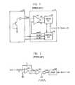
- FIG. 1is a block diagram of a conventional on-die thermal sensor.
- the conventional on-die thermal sensorincludes a band gap unit 100 and an analog-digital converter 110 .
- the band gap unit 100senses a temperature by using a characteristic of a bipolar junction transistor (BJT).
- a base-emitter voltage Vbe of the BJTchanges in the proportion of ⁇ 1.8 mV/° C. per temperature changes. Accordingly, the band gap unit 100 amplifies the small change base-emitter voltage Vbe and outputs a first voltage Vtemp changing in the proportion of one to one per unit temperature change. As temperature increases, the first voltage Vtemp decreases.
- the analog-digital converter 110includes a voltage comparing unit 120 , a counting unit 130 , and a converting unit 140 .
- the analog-digital converter 110converts the first voltage Vtemp output from the band gap unit 100 into a thermal code which is a digital code.
- the converting unit 140is a digital-analog converter.
- the converting unit 140outputs an analog second voltage DACOUT in response to the thermal code output from the counting unit 130 .
- Voltages VULIMIT and VLLIMIT, input into the converting unit 140determine maximum and minimum values of the second voltage DACOUT, respectively.
- the voltage comparing unit 120compares the first voltage Vtemp and the second voltage DACOUT. When the first voltage Vtemp is less than the second voltage DACOUT, the voltage comparing unit 120 outputs a decease signal DEC for decreasing the thermal code determined in the counting unit 130 . When the first voltage Vtemp is higher than the second voltage DACOUT, the voltage comparing unit 120 outputs an increase signal INC for increasing the thermal code predetermined in the counting unit 130 .
- the counting unit 130receives the increase signal INC or the decrease signal DEC from the voltage comparing unit 120 .
- the counting unit 130increases or decreases a thermal code determined therein and outputs a thermal code representing temperature.
- the analog-digital converter 110compares the first voltage Vtemp with the second voltage DACOUT, and increases or decreases the thermal code repeatedly. Accordingly, the second voltage DACOUT tracks the first voltage Vtemp. When the tracking is finished, the thermal code becomes digital values corresponding to the first voltage Vtemp.
- the analog-digital converteruses a method in which the second voltage DACOUT tracks the first voltage Vtemp.
- This kind of analog-digital converteris called a tracking analog-digital converter.
- FIG. 2is a block diagram of a conventional integrating analog-digital converter.
- the conventional integrating analog-digital converterincludes an operational amplifier 210 , a resistor R, a capacitor C, a comparator 220 , an AND gate 230 , and a counter 240 .
- the operational amplifier 210integrates a negative reference voltage ⁇ Vref to output a second voltage Vout which increases as time passes. By counting clocks of a clock signal CLK input until the second voltage Vout reaches a first voltage Vin, the first voltage Vin is converted into a digital value.
- the operational amplifier 210performs the integration operation.
- the operational amplifier 210outputs the second voltage Vout which increases as time passes as shown in the following equation.
- V out( V ref/ RC )* t
- the comparator 220compares the second voltage Vout output from the operational amplifier 210 with the first voltage Vin to be converted into a digital value. When the first voltage Vin is higher than the second voltage Vout, the comparator 220 outputs a logic high level voltage. When the second voltage Vout is higher than the first voltage Vin, the comparator 220 outputs a logic low level voltage. Accordingly, while outputting a logic high level voltage at the initial operation, the comparator 220 outputs a logic low level voltage when the second voltage Vout becomes higher than the first voltage Vin as time passes.
- the AND gate 230receives an output of the comparator 220 and the clock signal CLK. When the output of the comparator 220 has a logic high level, the clock signal CLK is output to the counter 240 . When the output of the comparator 220 has a logic low level, the output of the AND gate 230 becomes a logic low level regardless of a logic state of the clock signal CLK.
- the counter 240counts the number of logic high levels of the output of the AND gate 230 to generate a digital code. That is, the counter 240 counts clocks of the clock signal CLK until the second voltage Vout becomes higher than the first voltage Vin and generates the digital code. As described above, the analog type of first voltage Vin is converted into the digital code.
- the integrating analog-digital converter shown in FIG. 2can perform the converting operation with fewer errors than a tracking analog-digital converter.
- a semiconductor memory devicehardly uses the integrating analog-digital converter because it is difficult to generate the negative reference voltage ⁇ Vref.
- the reference voltage input to the inverting terminalshould be negative to output the second voltage Vout being positive.
- an additional circuit for pumping the negative voltageis required to generate the negative reference voltage ⁇ Vref.
- the additional circuitmay increase a chip size and current consumption.
- Embodiments of the present inventionare directed to provide an integrating analog-digital converter not requiring a negative reference voltage input and an on-die thermal sensor that includes the integrating analog digital converter.
- an analog-digital converterincludes an integrating unit for integrating a difference between a reference voltage and a comparing voltage to output a second voltage, wherein the comparing voltage has a voltage level higher than that of the reference voltage, and a counting unit for counting clocks of a clock signal input thereto until the second voltage reaches a first voltage, thereby outputting a digital code corresponding to a voltage level of the first voltage.
- an on-die thermal sensorincludes a band gap unit for sensing a temperature to output a first voltage corresponding to the sensed temperature, an integrating unit for integrating a difference between a reference voltage and a comparing voltage to output a second voltage wherein the comparing voltage has a voltage level higher than that of the reference voltage, and a counting unit for counting clocks of a clock signal input thereto until the second voltage reaches the first voltage, thereby outputting a thermal code corresponding to the voltage level of the first voltage.
- an analog-digital converterincludes an integrating unit for integrating a difference between a reference voltage and a first voltage to output a second voltage, wherein the reference voltage has zero or a positive value, and a counting unit for counting clocks of a clock signal input thereto until the second voltage reaches a predetermined voltage, thereby outputting a digital code, wherein the first voltage is an analog type of voltage.
- an on-die thermal sensorincludes a band gap unit for sensing a temperature to output a first voltage corresponding to the sensed temperature, an integrating unit for integrating a difference between a reference voltage and a first voltage to output a second voltage, wherein the reference voltage has zero or a positive value, and a counting unit for counting clocks of a clock signal input thereto until the second voltage reaches a predetermined voltage, thereby outputting a thermal code corresponding to a voltage level of the first voltage.
- an analog-digital converterincludes an integrating unit for integrating a difference between a first voltage and a comparing voltage to output a second voltage, wherein the comparing voltage has a voltage level higher than that of the first voltage, and a counting unit for counting clocks of a clock signal input thereto until the second voltage reaches a predetermined voltage, thereby outputting a digital code, wherein the first voltage is an analog voltage.
- an on-die thermal sensorincludes a band gap unit for sensing a temperature to output a first voltage corresponding to the temperature, an integrating unit for integrating a difference between a first voltage and a comparing voltage to output a second voltage, wherein the comparing voltage has a voltage level higher than that of the first voltage, and a counting unit for counting clocks of a clock signal input thereto until the second voltage reaches a predetermined voltage, thereby outputting a thermal code corresponding to a level of the first voltage.
- FIG. 1is a block diagram of a conventional on-die thermal sensor that includes an analog-digital converter.
- FIG. 2is a block diagram of a conventional integrating analog-digital converter.
- FIG. 3is a block diagram of an integrating analog-digital converter in accordance with a first embodiment of the present invention.
- FIG. 4is a block diagram of an on-die thermal sensor that includes an analog-digital converter in accordance with a first embodiment of the present invention.
- FIG. 5is a block diagram of an analog-digital converter and an on-die thermal sensor that includes the converter in accordance with second embodiment of the present invention.
- FIG. 6is a block diagram of an analog-digital converter and an on-die thermal sensor that includes the converter in accordance with third embodiment of the present invention.
- An integrating analog-digital converter in accordance with the present inventionneed not use a negative voltage. There is no need for an additional charge pump to generate a negative voltage. Moreover, no need for a negative reference voltage makes the integrating analog-digital converter widely applied to apparatuses such as an on-die thermal device
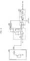
- FIG. 3is a block diagram of an integrating analog-digital converter in accordance with a first embodiment of the present invention.
- the integrating analog-digital converterincludes an integrating unit 310 and a counting unit 320 .
- the integrating unit 310receives a reference voltage Vref having zero or a positive value through an inverting terminal and a comparing voltage Vx, higher than the reference voltage Vref, through a noninverting terminal.
- the integrating unit 310integrates a difference between the reference voltage Vref and the comparing voltage Vx and outputs a second voltage Vout 1 .
- the counting unit 320counts clock signal input until the second voltage Vout 1 reaches a level of a first voltage Vin 1 which would be converted into a digital value. And then, the counting unit 320 outputs a digital code corresponding to the level of the first voltage Vin 1 .
- the integrating unit 310includes an operational amplifier 311 , a resistor R 1 and a capacitor C 1 .
- the operational amplifier 311receives the comparing voltage Vx through a noninverting terminal.
- the resistor R 1is connected to an inverting terminal of the operational amplifier 311 and receives the reference voltage Vref.
- the capacitor C 1is connected between the inverting terminal and an output terminal of the operational amplifier 311
- the counting unit 320includes a comparator 321 , an AND gate 322 and a counter 323 .
- the comparator 321compares the first voltage Vin 1 and the second voltage Vout 1 .
- the AND gate 322receives a clock signal CLK and an output of the comparator 321 .
- the counter 323counts an output of the AND gate 322 and outputs the digital code.
- V out⁇ Vx ⁇ V ref)/ RC ⁇ *t+Vx (Vx>Vref)
- the values Vx, Vref, R and Care constants.
- the second voltage Vout 1increases over time the same as the conventional second voltage Vout does.
- the comparator 321compares the second voltage Vout 1 output from the operational amplifier 311 with the first voltage Vin 1 to be converted into a digital value. When the first voltage Vin 1 is higher than the second voltage Vout 1 , the comparator 321 outputs a high logic level of voltage. When the second voltage Vout 1 is higher than the first voltage Vin 1 , the comparator 321 outputs a low logic level of voltage. Accordingly, while outputting a high logic level of voltage at the initial operation, the comparator 321 outputs a low logic level voltage when the second voltage Vout 1 becomes higher than the first voltage Vin 1 over time.
- the AND gate 322receives an output of the comparator 321 and the clock signal CLK.
- the clock signal CLKis inputted to the counter 323 .
- an output of the AND gate 322becomes a low logic level regardless of the clock signal CLK.
- the counter 323counts high logic levels of the output of the AND gate 322 and generates a digital value. That is, the counter 323 counts clock signal input until the second voltage Vout 1 becomes higher than the first voltage Vin 1 and generates the digital code. As described above, the analog first voltage Vin 1 is converted into the digital value.
- the integrating analog-digital converter in accordance with the present inventionreceives the comparing voltage Vx through the noninverting terminal of the operational amplifier 311 .
- the comparing voltage Vxis higher than the reference voltage Vref. Accordingly, the reference voltage Vref has a positive value and there is no need for pumping a negative voltage.
- the analog-digital convertermay further include a controller 330 .
- the controller 330controls enablement of the integrating unit 310 by shorting or breaking both terminals of the capacitor C 1 .
- the controller 330controls enablement of the counting unit 320 by inputting a low level or a high level signal to the AND gate 322 .
- FIG. 4illustrates a block diagram of an on-die thermal sensor that includes the analog-digital converter in accordance with the present invention.
- the on-die thermal sensorincludes a band gap unit 400 , an integrating unit 410 and a counting unit 420 .
- the band gap unit 400senses a temperature and outputs a first voltage Vtemp corresponding to the temperature.
- the integrating unit 410receives a reference voltage Vref having zero or a positive value through an inverting terminal and a comparing voltage Vx higher than the reference voltage Vref through a noninverting terminal.
- the integrating unit 410integrates a difference between the reference voltage Vref and the comparing voltage Vx and outputs a second voltage Vout 1 .
- the counting unit 420counts clock signal input until the second voltage Vout 1 reaches a level of the first voltage Vtemp. And then, the counting unit 420 outputs a thermal code corresponding to the level of the first voltage Vtemp.
- the integrating unit 410includes an operational amplifier 411 , a resistor R 1 and a capacitor C 1 .
- the operational amplifier 411receives the comparing voltage Vx through a noninverting terminal.
- the resistor R 1is connected to an inverting terminal of the operational amplifier 411 and receives the reference voltage Vref.
- the capacitor C 1is connected between the inverting terminal and an output terminal of the operational amplifier 411 .
- the counting unit 420includes a comparator 421 , an AND gate 422 and a counter 423 .
- the comparator 421compares the first voltage Vtemp and the second voltage Vout 1 .
- the AND gate 422receives a clock signal CLK and an output of the comparator 421 .
- the counter 423counts an output of the AND gate 422 and outputs the thermal code.
- the on die thermal sensormay further include a controller 430 for controlling enablement of the integrating unit 410 and the counting unit 420 .
- the band gap unit 400outputs the first voltage Vtemp representing a temperature by using a base-emitter voltage Vbe of a BJT the same as the conventional band gap unit does. Moreover the voltages Vref and Vx having a constant value in spite of a temperature change can be generated by the band gap unit 400 because the band gap unit 400 generally generates a variety of voltages according to a temperature change.
- the analog-digital converters of the on-die thermal sensor described in FIG. 4is identical to that in FIG. 3 , including the integrating unit 410 and counting unit 420 .
- the first voltage Vtemp output from the band gap unit 400is an input into a noninverting terminal of the comparator 421 to be converted into a digital value.
- the thermal code output from the on die thermal sensoris a digital code corresponding to a level of the first voltage Vtemp.
- FIG. 5illustrates a block diagram of an analog-digital converter and an on-die thermal sensor that includes the converter in accordance with a second embodiment of the present invention.
- a terminal to which a first voltage Vtemp is inputtedis different in the first and second embodiments. However, no negative voltage is required in both embodiments.
- the analog-digital converter in accordance with the second embodimentincludes an integrating unit 510 and a counting unit 520 .
- the integrating unit 510receives a reference voltage Vref having zero or a positive value through an inverting terminal and a first voltage Vtemp higher than the reference voltage Vref through a noninverting terminal.
- the first voltage Vtempis an analog voltage to be converted into a digital value.
- the integrating unit 510integrates a difference between the reference voltage Vref and the first voltage Vtemp and outputs a second voltage Vout 2 .
- the counting unit 520counts clock signal input until the second voltage Vout 2 reaches a level of a predetermined voltage V 1 . And then, the counting unit 520 outputs a thermal code corresponding to the level of the first voltage Vtemp.
- the integrating unit 510includes an operational amplifier 511 , a resistor R 2 and a capacitor C 2 .
- the operational amplifier 511receives the first voltage Vtemp through a noninverting terminal.
- the resistor R 2is connected to an inverting terminal of the operational amplifier 511 and receives the reference voltage Vref.
- the capacitor C 2is connected between the inverting terminal and an output terminal of the operational amplifier 511 .
- the counting unit 520includes a comparator 521 , an AND gate 522 and a counter 523 .
- the comparator 521compares the predetermined voltage V 1 with the second voltage Vout 2 .
- the AND gate 522receives a clock signal CLK and an output of the comparator 521 .
- the counter 523counts an output of the AND gate 522 and outputs the thermal code.
- V out2⁇ V temp ⁇ V ref)/ RC ⁇ *t+V temp
- the only voltage Vxis substituted for the voltage Vtemp in the equation regarding the second voltage Vout 1 in accordance with the first embodiment.
- the second voltage Vout 2increases over time and an increment depends on a level of first voltage Vtemp. The higher the first voltage Vtemp is, the faster the second voltage Vout 2 increases.
- Clock signal inputis counted until the second voltage Vout 2 reaches a level of the predetermined voltage V 1 .
- the time taken for the second voltage Vout 2 to reach a level of the predetermined voltage V 1depends on the first voltage Vtemp.
- the thermal codebecomes different according to the level of the first voltage Vtemp. That is, an analog type of the first voltage Vtemp can be converted into a digital thermal code corresponding to its level.
- the predetermined voltage V 1should be set to be higher than the first voltage Vtemp, because the counting is performed until the second voltage Vout 2 , i.e., ⁇ Vtemp ⁇ Vref)/RC ⁇ *t+Vtemp, reaches the level of the predetermined voltage V 1 .
- the first voltage Vtempshould be higher than the reference voltage Vref in the second embodiment the same as the comparing voltage Vx should be in the first embodiment.
- the on die thermal sensor in accordance with the second embodimentis provided by adding a band gap unit 500 to the above analog-digital converter.
- An output voltage of the band gap unit 500corresponding to a temperature, becomes the first voltage Vtemp. Because the first voltage Vtemp should be higher than the reference voltage Vref, the band gap unit 500 can use a level shifter circuit to control a level of the first voltage Vtemp.
- FIG. 6illustrates a block diagram of an analog-digital converter and an on die thermal sensor that includes the converter in accordance with third embodiment of the present invention.
- a terminal to which a first voltage Vtemp is inputted in the third embodimentis different from those in the first and second embodiments. However, no negative voltage is required like the first and the second embodiments.
- the analog-digital converter in accordance with the third embodimentincludes an integrating unit 610 and a counting unit 620 .
- the integrating unit 610receives the first voltage Vtemp through an inverting terminal and a comparing voltage Vx higher than the first voltage Vtemp through a noninverting terminal.
- the first voltage Vtempis an analog voltage to be converted into a digital value.
- the integrating unit 610integrates a difference between the first voltage Vtemp and the comparing voltage Vx and outputs a second voltage Vout 3 .
- the counting unit 620counts clock signal input until the second voltage Vout 3 reaches a level of a predetermined voltage V 1 . And then, the counting unit 620 outputs a thermal code corresponding to the level of the first voltage Vtemp.
- the integrating unit 610includes an operational amplifier 611 , a resistor R 3 and a capacitor C 3 .
- the operational amplifier 611receives the comparing voltage Vx through a noninverting terminal.
- the resistor R 3is connected to an inverting terminal of the operational amplifier 611 and receives the first voltage Vtemp.
- the capacitor C 3is connected between the inverting terminal and an output terminal of the operational amplifier 611 .
- the counting unit 620includes a comparator 621 , an AND gate 622 and a counter 623 .
- the comparator 621compares the predetermined voltage V 1 and the second voltage Vout 3 .
- the AND gate 622receives a clock signal CLK and an output of the comparator 621 .
- the counter 623counts an output of the AND gate 622 and outputs the thermal code.
- V out3⁇ Vx ⁇ V temp)/ RC ⁇ *t+Vx
- the only voltage Vrefis substituted for the voltage Vtemp in the equation regarding the second voltage Vout 1 in accordance with the first embodiment.
- the second voltage Vout 3increases over time and an increment depends on a level of first voltage Vtemp. The lower the first voltage Vtemp is, the faster the second voltage Vout 3 increases.
- Clock signal inputis counted until the second voltage Vout 3 reaches a level of the predetermined voltage V 1 .
- a time taken for the second voltage Vout 3 to reach a level of the predetermined voltage V 1depends on the first voltage Vtemp.
- the thermal codebecomes different according to the level of the first voltage Vtemp. That is, an analog first voltage Vtemp can be converted into a digital thermal code corresponding to its level.
- the predetermined voltage V 1should be set to be higher than the comparing voltage Vx, because the counting is performed until the second voltage Vout 3 , i.e., ⁇ Vx ⁇ Vtemp)/RC ⁇ *t+Vx, reaches the level of the predetermined voltage V 1 .
- the comparing voltage Vxshould be higher than the first voltage Vtemp in the third embodiment as the comparing voltage Vx should be higher than the reference voltage Vref in the first embodiment.
- the on-die thermal sensor in accordance with the third embodimentis provided by adding a band gap unit 600 to the above analog-digital converter.
- An output voltage of the band gap unit 600corresponding to a temperature, becomes the first voltage Vtemp. Because the first voltage Vtemp should be lower than the comparing voltage Vx, the band gap unit 600 can use a level shifter circuit to control a level of the first voltage Vtemp.
- a conventional on-die thermal sensor used in a semiconductor memory deviceuses a tracking analog-digital converter.
- the on die thermal sensor in accordance with the present inventioncan use the integrating analog-digital converter without the need for a negative reference voltage. Therefore, the on die thermal sensor can be widely used in a semiconductor memory device
Landscapes
- Engineering & Computer Science (AREA)
- Theoretical Computer Science (AREA)
- Physics & Mathematics (AREA)
- General Physics & Mathematics (AREA)
- Analogue/Digital Conversion (AREA)
- Measuring Temperature Or Quantity Of Heat (AREA)
Abstract
Description
{(0−Vref)/R}=C{d(0−Vout)/dt}
Vout=(Vref/RC)*t
{(Vx−Vref)/R}=C{d(Vx−Vout1)/dt}
Vout={Vx−Vref)/RC}*t+Vx(Vx>Vref)
Vout2={Vtemp−Vref)/RC}*t+Vtemp
Vout3={Vx−Vtemp)/RC}*t+Vx
Claims (25)
Applications Claiming Priority (3)
| Application Number | Priority Date | Filing Date | Title |
|---|---|---|---|
| KR2007-0009864 | 2007-01-31 | ||
| KR10-2007-0009864 | 2007-01-31 | ||
| KR1020070009864AKR100909251B1 (en) | 2007-01-31 | 2007-01-31 | Analog-to-digital converter and temperature information output device including the same |
Publications (2)
| Publication Number | Publication Date |
|---|---|
| US20080180300A1 US20080180300A1 (en) | 2008-07-31 |
| US7880661B2true US7880661B2 (en) | 2011-02-01 |
Family
ID=39667339
Family Applications (1)
| Application Number | Title | Priority Date | Filing Date |
|---|---|---|---|
| US11/819,816ActiveUS7880661B2 (en) | 2007-01-31 | 2007-06-29 | Analog-digital converter and on-die thermal sensor including the same |
Country Status (3)
| Country | Link |
|---|---|
| US (1) | US7880661B2 (en) |
| JP (1) | JP4982698B2 (en) |
| KR (1) | KR100909251B1 (en) |
Cited By (3)
| Publication number | Priority date | Publication date | Assignee | Title |
|---|---|---|---|---|
| US20090323764A1 (en)* | 2008-06-30 | 2009-12-31 | Hynix Semiconductor, Inc. | Temperature sensing circuit, on die thermal sensor including the same, and method for sensing temperature |
| US20090323758A1 (en)* | 2008-06-30 | 2009-12-31 | Hynix Semiconductor, Inc. | Analog-digital converter and temperature information output device having the same |
| CN102750057A (en)* | 2011-04-21 | 2012-10-24 | 硅工厂股份有限公司 | Touch sensing circuit |
Families Citing this family (7)
| Publication number | Priority date | Publication date | Assignee | Title |
|---|---|---|---|---|
| KR100655076B1 (en)* | 2005-01-20 | 2006-12-08 | 삼성전자주식회사 | Internal temperature data output method of semiconductor memory device and corresponding internal temperature data output circuit |
| KR100845811B1 (en)* | 2007-09-05 | 2008-07-14 | 주식회사 하이닉스반도체 | Digital / Analog Conversion Circuit and On-Determination Control Device Using the Same |
| US8704484B2 (en)* | 2010-05-28 | 2014-04-22 | Qualcomm Incorporated | Temperature sensor interface for wireless and wired charging |
| KR101365340B1 (en)* | 2012-05-31 | 2014-02-19 | 삼성전기주식회사 | Circuit and method for sensing temperature |
| CN105981104B (en)* | 2014-03-05 | 2019-07-05 | 英特尔公司 | The equipment of adaptive write-in auxiliary for memory |
| KR102621778B1 (en) | 2019-08-12 | 2024-01-09 | 에스케이하이닉스 주식회사 | Data Storage Apparatus, Trimming Circuit and Method for Internal Voltage Therefor |
| KR102630096B1 (en) | 2019-08-23 | 2024-01-29 | 에스케이하이닉스 주식회사 | Data Storage Apparatus, Trimming Circuit and Method of Internal Voltage Therefor |
Citations (33)
| Publication number | Priority date | Publication date | Assignee | Title |
|---|---|---|---|---|
| US3316547A (en)* | 1964-07-15 | 1967-04-25 | Fairchild Camera Instr Co | Integrating analog-to-digital converter |
| US3849775A (en)* | 1972-10-24 | 1974-11-19 | Westinghouse Electric Corp | Ac analog to digital converter |
| US3895376A (en)* | 1971-10-26 | 1975-07-15 | Iwatsu Electric Co Ltd | Dual slope integrating analog to digital converter |
| US4243974A (en)* | 1978-02-24 | 1981-01-06 | E. I. Du Pont De Nemours And Company | Wide dynamic range analog to digital converter |
| US4268820A (en)* | 1977-09-09 | 1981-05-19 | Nippon Electric Co., Ltd. | Integrating type analog-to-digital converter |
| US4448549A (en)* | 1981-03-10 | 1984-05-15 | Citizen Watch Company Limited | Temperature sensing device |
| US4567465A (en)* | 1982-05-25 | 1986-01-28 | Iwatsu Electric Co., Ltd. | Method and apparatus for converting analog signal into digital signal |
| US4746901A (en)* | 1985-08-15 | 1988-05-24 | Itt Corporation | High precision analog to digital converter |
| US5101206A (en)* | 1989-12-05 | 1992-03-31 | Hewlett-Packard Company | Integrating analog to digital converter |
| US5117227A (en)* | 1991-09-27 | 1992-05-26 | Hewlett-Packard Company | Continuously integrating high-resolution analog-to-digital converter |
| US5177696A (en)* | 1989-12-28 | 1993-01-05 | Honeywell Inc. | Method of determination of gas properties at reference conditions |
| US5245646A (en)* | 1992-06-01 | 1993-09-14 | Motorola, Inc. | Tuning circuit for use with an integrated continuous time analog filter |
| US5323156A (en)* | 1991-11-13 | 1994-06-21 | Endress+Hauser Flowtec Ag | Delta-sigma analog-to-digital converter |
| JPH10255467A (en) | 1996-12-23 | 1998-09-25 | Lsi Logic Corp | Memory system including on-chip temperature sensor to adjust refresh speed of dram array |
| US6016051A (en)* | 1998-09-30 | 2000-01-18 | National Semiconductor Corporation | Bandgap reference voltage circuit with PTAT current source |
| US6243034B1 (en)* | 1998-10-29 | 2001-06-05 | National Instruments Corporation | Integrating analog to digital converter with improved resolution |
| KR20020014516A (en) | 2000-08-18 | 2002-02-25 | 박종섭 | Reference voltage generator for independent of temperature variation and substrate noise |
| US6531911B1 (en) | 2000-07-07 | 2003-03-11 | Ibm Corporation | Low-power band-gap reference and temperature sensor circuit |
| JP2003143011A (en) | 2001-11-05 | 2003-05-16 | Fuji Electric Co Ltd | Analog-digital conversion circuit |
| US6717393B2 (en)* | 2002-04-11 | 2004-04-06 | Texas Instruments Incorporated | System for difference calculation using a quad slope converter |
| US20040090826A1 (en)* | 2002-11-12 | 2004-05-13 | Ryu Ogiwara | Semiconductor device having semiconductor memory with sense amplifier |
| JP2004165905A (en) | 2002-11-12 | 2004-06-10 | Hitachi Ulsi Systems Co Ltd | Semiconductor integrated circuit |
| KR20050082636A (en) | 2004-02-19 | 2005-08-24 | 주식회사 하이닉스반도체 | Analogue-digital converter |
| JP2005285125A (en) | 2004-03-26 | 2005-10-13 | Samsung Electronics Co Ltd | Memory module system that effectively controls ODT |
| US6958613B2 (en) | 2002-09-30 | 2005-10-25 | Infineon Technologies Ag | Method for calibrating semiconductor devices using a common calibration reference and a calibration circuit |
| US6980020B2 (en) | 2003-12-19 | 2005-12-27 | Rambus Inc. | Calibration methods and circuits for optimized on-die termination |
| JP2006129423A (en) | 2004-10-30 | 2006-05-18 | Hynix Semiconductor Inc | Semiconductor memory device equipped with on-die termination circuit |
| US7151390B2 (en) | 2003-09-08 | 2006-12-19 | Rambus Inc. | Calibration methods and circuits for optimized on-die termination |
| US7170313B2 (en) | 2004-04-28 | 2007-01-30 | Hynix Semiconductor Inc. | Apparatus for calibrating termination voltage of on-die termination |
| US7176711B2 (en) | 2004-04-28 | 2007-02-13 | Hynix Semiconductor Inc. | On-die termination impedance calibration device |
| US20070126615A1 (en)* | 2005-12-06 | 2007-06-07 | Yi Gyeong Kim | Multi-bit sigma-delta modulator and digital-to-analog converter with one digital-to-analog capacitor |
| US20080054987A1 (en)* | 2006-07-13 | 2008-03-06 | Choi Yun-Seok | Gate-on voltage generator, driving device and display apparatus comprising the same |
| US20080095213A1 (en)* | 2006-10-21 | 2008-04-24 | Intersil Americas Inc. | CMOS temperature-to-digital converter with digital correction |
Family Cites Families (4)
| Publication number | Priority date | Publication date | Assignee | Title |
|---|---|---|---|---|
| JPS54138362A (en)* | 1978-04-19 | 1979-10-26 | Toshiba Corp | Analog-digital conversion unit |
| JPS59117821A (en)* | 1982-12-24 | 1984-07-07 | Sanden Corp | Analog-digital convertor |
| JP3632822B2 (en)* | 1998-09-29 | 2005-03-23 | 横河電機株式会社 | Temperature transmitter input circuit |
| JP3815607B2 (en)* | 2001-11-16 | 2006-08-30 | 横河電機株式会社 | Temperature transmitter using analog-digital converter |
- 2007
- 2007-01-31KRKR1020070009864Apatent/KR100909251B1/enactiveActive
- 2007-05-10JPJP2007125325Apatent/JP4982698B2/enactiveActive
- 2007-06-29USUS11/819,816patent/US7880661B2/enactiveActive
Patent Citations (33)
| Publication number | Priority date | Publication date | Assignee | Title |
|---|---|---|---|---|
| US3316547A (en)* | 1964-07-15 | 1967-04-25 | Fairchild Camera Instr Co | Integrating analog-to-digital converter |
| US3895376A (en)* | 1971-10-26 | 1975-07-15 | Iwatsu Electric Co Ltd | Dual slope integrating analog to digital converter |
| US3849775A (en)* | 1972-10-24 | 1974-11-19 | Westinghouse Electric Corp | Ac analog to digital converter |
| US4268820A (en)* | 1977-09-09 | 1981-05-19 | Nippon Electric Co., Ltd. | Integrating type analog-to-digital converter |
| US4243974A (en)* | 1978-02-24 | 1981-01-06 | E. I. Du Pont De Nemours And Company | Wide dynamic range analog to digital converter |
| US4448549A (en)* | 1981-03-10 | 1984-05-15 | Citizen Watch Company Limited | Temperature sensing device |
| US4567465A (en)* | 1982-05-25 | 1986-01-28 | Iwatsu Electric Co., Ltd. | Method and apparatus for converting analog signal into digital signal |
| US4746901A (en)* | 1985-08-15 | 1988-05-24 | Itt Corporation | High precision analog to digital converter |
| US5101206A (en)* | 1989-12-05 | 1992-03-31 | Hewlett-Packard Company | Integrating analog to digital converter |
| US5177696A (en)* | 1989-12-28 | 1993-01-05 | Honeywell Inc. | Method of determination of gas properties at reference conditions |
| US5117227A (en)* | 1991-09-27 | 1992-05-26 | Hewlett-Packard Company | Continuously integrating high-resolution analog-to-digital converter |
| US5323156A (en)* | 1991-11-13 | 1994-06-21 | Endress+Hauser Flowtec Ag | Delta-sigma analog-to-digital converter |
| US5245646A (en)* | 1992-06-01 | 1993-09-14 | Motorola, Inc. | Tuning circuit for use with an integrated continuous time analog filter |
| JPH10255467A (en) | 1996-12-23 | 1998-09-25 | Lsi Logic Corp | Memory system including on-chip temperature sensor to adjust refresh speed of dram array |
| US6016051A (en)* | 1998-09-30 | 2000-01-18 | National Semiconductor Corporation | Bandgap reference voltage circuit with PTAT current source |
| US6243034B1 (en)* | 1998-10-29 | 2001-06-05 | National Instruments Corporation | Integrating analog to digital converter with improved resolution |
| US6531911B1 (en) | 2000-07-07 | 2003-03-11 | Ibm Corporation | Low-power band-gap reference and temperature sensor circuit |
| KR20020014516A (en) | 2000-08-18 | 2002-02-25 | 박종섭 | Reference voltage generator for independent of temperature variation and substrate noise |
| JP2003143011A (en) | 2001-11-05 | 2003-05-16 | Fuji Electric Co Ltd | Analog-digital conversion circuit |
| US6717393B2 (en)* | 2002-04-11 | 2004-04-06 | Texas Instruments Incorporated | System for difference calculation using a quad slope converter |
| US6958613B2 (en) | 2002-09-30 | 2005-10-25 | Infineon Technologies Ag | Method for calibrating semiconductor devices using a common calibration reference and a calibration circuit |
| JP2004165905A (en) | 2002-11-12 | 2004-06-10 | Hitachi Ulsi Systems Co Ltd | Semiconductor integrated circuit |
| US20040090826A1 (en)* | 2002-11-12 | 2004-05-13 | Ryu Ogiwara | Semiconductor device having semiconductor memory with sense amplifier |
| US7151390B2 (en) | 2003-09-08 | 2006-12-19 | Rambus Inc. | Calibration methods and circuits for optimized on-die termination |
| US6980020B2 (en) | 2003-12-19 | 2005-12-27 | Rambus Inc. | Calibration methods and circuits for optimized on-die termination |
| KR20050082636A (en) | 2004-02-19 | 2005-08-24 | 주식회사 하이닉스반도체 | Analogue-digital converter |
| JP2005285125A (en) | 2004-03-26 | 2005-10-13 | Samsung Electronics Co Ltd | Memory module system that effectively controls ODT |
| US7170313B2 (en) | 2004-04-28 | 2007-01-30 | Hynix Semiconductor Inc. | Apparatus for calibrating termination voltage of on-die termination |
| US7176711B2 (en) | 2004-04-28 | 2007-02-13 | Hynix Semiconductor Inc. | On-die termination impedance calibration device |
| JP2006129423A (en) | 2004-10-30 | 2006-05-18 | Hynix Semiconductor Inc | Semiconductor memory device equipped with on-die termination circuit |
| US20070126615A1 (en)* | 2005-12-06 | 2007-06-07 | Yi Gyeong Kim | Multi-bit sigma-delta modulator and digital-to-analog converter with one digital-to-analog capacitor |
| US20080054987A1 (en)* | 2006-07-13 | 2008-03-06 | Choi Yun-Seok | Gate-on voltage generator, driving device and display apparatus comprising the same |
| US20080095213A1 (en)* | 2006-10-21 | 2008-04-24 | Intersil Americas Inc. | CMOS temperature-to-digital converter with digital correction |
Non-Patent Citations (4)
| Title |
|---|
| Jong-Man, Im et al., "A High Accuracy CMOS Temperature Sensor in DRAM," Division of Electrical and Computer Engineering, Hanyang University, Ichon, Korea. |
| Jong-Man, Im et al., "High Resolution CMOS Temperature Sensor with Single Slope A/D Converter," Division of Electrical and Computer Engineering, Hanyang University, Ichon, Korea. |
| Korean Office Action, with English translation, issued in Korean Patent Application No. KR 10-2007-0009864, mailed Apr. 28, 2008. |
| Korean Office Action, with partial English translation, issued in Korean Patent Application No. KR 10-2007-0009864, mailed Jan. 5, 2009. |
Cited By (5)
| Publication number | Priority date | Publication date | Assignee | Title |
|---|---|---|---|---|
| US20090323764A1 (en)* | 2008-06-30 | 2009-12-31 | Hynix Semiconductor, Inc. | Temperature sensing circuit, on die thermal sensor including the same, and method for sensing temperature |
| US20090323758A1 (en)* | 2008-06-30 | 2009-12-31 | Hynix Semiconductor, Inc. | Analog-digital converter and temperature information output device having the same |
| CN102750057A (en)* | 2011-04-21 | 2012-10-24 | 硅工厂股份有限公司 | Touch sensing circuit |
| US20120268144A1 (en)* | 2011-04-21 | 2012-10-25 | Silicon Works Co., Ltd | Touch sensing circuit |
| US8841927B2 (en)* | 2011-04-21 | 2014-09-23 | Silicon Works Co., Ltd. | Touch sensing circuit |
Also Published As
| Publication number | Publication date |
|---|---|
| JP4982698B2 (en) | 2012-07-25 |
| JP2008193650A (en) | 2008-08-21 |
| KR100909251B1 (en) | 2009-07-23 |
| US20080180300A1 (en) | 2008-07-31 |
| KR20080071688A (en) | 2008-08-05 |
Similar Documents
| Publication | Publication Date | Title |
|---|---|---|
| US7880661B2 (en) | Analog-digital converter and on-die thermal sensor including the same | |
| US5619430A (en) | Microcontroller with on-chip linear temperature sensor | |
| JP4982677B2 (en) | Temperature information output device | |
| US5841996A (en) | Serial communication interface system having programmable microcontroller for use in a battery pack | |
| CN101782439B (en) | Ratio meter for temperature sensor | |
| US9587994B2 (en) | Semiconductor device | |
| WO1997013189A1 (en) | Microcontroller with analog front-end for providing intelligent battery management | |
| US8183907B2 (en) | Detection circuit and sensor device | |
| WO1997012310A9 (en) | Digital trimming of on-chip analog components | |
| JP5591294B2 (en) | Temperature information output device and memory device including the same | |
| US9103695B2 (en) | Detection circuit for detecting signals produced by bridge circuit sensor | |
| CN100434886C (en) | Low Power Consumption and Small Circuit Area Temperature Sensor | |
| US7990305B2 (en) | Current mode double-integration conversion apparatus | |
| US20120133353A1 (en) | Power-supply-voltage detecting circuit | |
| US20090323758A1 (en) | Analog-digital converter and temperature information output device having the same | |
| US7936204B2 (en) | Temperature sensing circuit | |
| CN112311230A (en) | Integrated circuit device | |
| US7026972B2 (en) | A/D converter | |
| KR20080114196A (en) | Analog-to-digital converter, temperature information output device including the same and method of performing the same | |
| US9880575B2 (en) | Power converter and method of use | |
| KR100283658B1 (en) | Temperature Detection Compensation Circuit and Compensation Method | |
| US7905657B2 (en) | Temperature sensor | |
| JP6390451B2 (en) | Battery block discharge control device | |
| KR100857856B1 (en) | Temperature information output device and semiconductor memory device including the same | |
| US20140218004A1 (en) | Integrated circuit with multi-functional parameter setting and multi-functional parameter setting method thereof |
Legal Events
| Date | Code | Title | Description |
|---|---|---|---|
| AS | Assignment | Owner name:HYNIX SEMICONDUCTOR INC., KOREA, REPUBLIC OF Free format text:ASSIGNMENT OF ASSIGNORS INTEREST;ASSIGNORS:JEONG, CHUN-SEOK;LEE, JAE-JIN;KIH, JOONG-SIK;AND OTHERS;REEL/FRAME:019546/0125 Effective date:20070628 | |
| FEPP | Fee payment procedure | Free format text:PAYOR NUMBER ASSIGNED (ORIGINAL EVENT CODE: ASPN); ENTITY STATUS OF PATENT OWNER: LARGE ENTITY | |
| AS | Assignment | Owner name:INDUSTRY-UNIVERSITY COOPERATION FOUNDATION HANYANG Free format text:ASSIGNMENT OF ASSIGNORS INTEREST;ASSIGNOR:HYNIX SEMICONDUCTOR INC.;REEL/FRAME:025524/0806 Effective date:20101126 Owner name:HYNIX SEMICONDUCTOR INC., KOREA, REPUBLIC OF Free format text:ASSIGNMENT OF ASSIGNORS INTEREST;ASSIGNOR:HYNIX SEMICONDUCTOR INC.;REEL/FRAME:025524/0806 Effective date:20101126 | |
| STCF | Information on status: patent grant | Free format text:PATENTED CASE | |
| FPAY | Fee payment | Year of fee payment:4 | |
| MAFP | Maintenance fee payment | Free format text:PAYMENT OF MAINTENANCE FEE, 8TH YEAR, LARGE ENTITY (ORIGINAL EVENT CODE: M1552) Year of fee payment:8 | |
| MAFP | Maintenance fee payment | Free format text:PAYMENT OF MAINTENANCE FEE, 12TH YEAR, LARGE ENTITY (ORIGINAL EVENT CODE: M1553); ENTITY STATUS OF PATENT OWNER: LARGE ENTITY Year of fee payment:12 |