US7879104B2 - Spinal implant system - Google Patents
Spinal implant systemDownload PDFInfo
- Publication number
- US7879104B2 US7879104B2US11/560,169US56016906AUS7879104B2US 7879104 B2US7879104 B2US 7879104B2US 56016906 AUS56016906 AUS 56016906AUS 7879104 B2US7879104 B2US 7879104B2
- Authority
- US
- United States
- Prior art keywords
- core
- fork
- use position
- relative
- spinous process
- Prior art date
- Legal status (The legal status is an assumption and is not a legal conclusion. Google has not performed a legal analysis and makes no representation as to the accuracy of the status listed.)
- Expired - Fee Related, expires
Links
Images


Classifications
- A—HUMAN NECESSITIES
- A61—MEDICAL OR VETERINARY SCIENCE; HYGIENE
- A61B—DIAGNOSIS; SURGERY; IDENTIFICATION
- A61B17/00—Surgical instruments, devices or methods
- A61B17/56—Surgical instruments or methods for treatment of bones or joints; Devices specially adapted therefor
- A61B17/58—Surgical instruments or methods for treatment of bones or joints; Devices specially adapted therefor for osteosynthesis, e.g. bone plates, screws or setting implements
- A61B17/68—Internal fixation devices, including fasteners and spinal fixators, even if a part thereof projects from the skin
- A61B17/70—Spinal positioners or stabilisers, e.g. stabilisers comprising fluid filler in an implant
- A61B17/7062—Devices acting on, attached to, or simulating the effect of, vertebral processes, vertebral facets or ribs ; Tools for such devices
- A61B17/7065—Devices with changeable shape, e.g. collapsible or having retractable arms to aid implantation; Tools therefor
- A—HUMAN NECESSITIES
- A61—MEDICAL OR VETERINARY SCIENCE; HYGIENE
- A61B—DIAGNOSIS; SURGERY; IDENTIFICATION
- A61B17/00—Surgical instruments, devices or methods
- A61B17/56—Surgical instruments or methods for treatment of bones or joints; Devices specially adapted therefor
- A61B17/58—Surgical instruments or methods for treatment of bones or joints; Devices specially adapted therefor for osteosynthesis, e.g. bone plates, screws or setting implements
- A61B17/68—Internal fixation devices, including fasteners and spinal fixators, even if a part thereof projects from the skin
- A61B17/70—Spinal positioners or stabilisers, e.g. stabilisers comprising fluid filler in an implant
- A61B17/7053—Spinal positioners or stabilisers, e.g. stabilisers comprising fluid filler in an implant with parts attached to bones or to each other by flexible wires, straps, sutures or cables
- A—HUMAN NECESSITIES
- A61—MEDICAL OR VETERINARY SCIENCE; HYGIENE
- A61B—DIAGNOSIS; SURGERY; IDENTIFICATION
- A61B17/00—Surgical instruments, devices or methods
- A61B17/56—Surgical instruments or methods for treatment of bones or joints; Devices specially adapted therefor
- A61B17/58—Surgical instruments or methods for treatment of bones or joints; Devices specially adapted therefor for osteosynthesis, e.g. bone plates, screws or setting implements
- A61B17/68—Internal fixation devices, including fasteners and spinal fixators, even if a part thereof projects from the skin
- A61B17/84—Fasteners therefor or fasteners being internal fixation devices
- A61B17/842—Flexible wires, bands or straps
Definitions
- the present inventionrelates generally to the field of surgery and medical implants, and more particularly, to spinal implant systems and methods for inserting spinal implant systems.
- the human spineis a biomechanical structure with thirty-three vertebral members, and is responsible for protecting the spinal cord, nerve roots and internal organs of the thorax and abdomen.
- the spinealso provides structural support for the body while permitting flexibility of motion.
- a significant portion of the populationwill experience back pain at some point in their lives resulting from a spinal condition.
- the painmay range from general discomfort to disabling pain that immobilizes the individual.
- Back painmay result from a trauma to the spine, be caused by the natural aging process, or may be the result of a degenerative disease or condition.
- Procedures to remedy back problemssometimes require correcting the distance between vertebral members by inserting an intervertebral device (e.g., spacer) between the members.
- an intervertebral devicee.g., spacer
- Dynamic interspinous spacersare currently used to treat patients with a variety of indications. Essentially, these patients present a need for distraction of the posterior elements (e.g., the spinous processes) of the spine using a mechanical device.
- Current clinical indications for such a devicemay include stenosis, disc herniation, facet arthropathy, degenerative disc disease and adjacent segment degeneration.
- interspinous devicesinclude rigid and flexible spacers made from PEEK, titanium, silicone or some combination of other implantable materials.
- these devicesrequire an open technique to be implanted, and many require destroying important anatomical stabilizers, such as the supraspinous ligament.
- the current technique for placing such spacers between the interspinous processesis to cut the interspinous and supraspinous ligaments and slide the device over the adjacent spinous processes.
- an interspinous spacer systemwhich includes a core shaped and configured to fit in an interspinous space between adjacent spinous processes.
- a plurality of extending forksextends from the core and has shapes configured to extend along the vertical sides of the spinous processes.
- a first fork of the plurality of forksis moveable relative to the core from a non-use position to an in-use position.
- the first forkis located on a first side of the core when in the in-use position and has a first inner side bounding an opening for receiving a first spinous process of the spinous processes.
- the first forkis substantially non-flexible.
- a second forkis located on the first side of the core and the second fork has a second inner side bounding the opening for receiving the first spinous process of the spinous processes.
- the second forkis immovable relative to the core.
- the first forkavoids protruding from the core such that the first fork bounds the opening in the non-use position to allow the core to be inserted into the interspinous space in the non-use position to avoid damage to a supraspinous ligament adjacent the space.
- an interspinous spacer systemwhich includes a core having a shape configured to fit between adjacent spinous processes.
- a plurality of extending forksextends from the core and has shapes configured to extend along vertical sides of the spinous processes.
- a first fork and second fork of the plurality of forksare coupled to the core and moveable from a non-use position to an in-use position.
- the first fork and the second forkdefine an opening for receiving a first spinous process of the spinous processes when in an in-use position.
- the coreincludes a cavity defined by inner surfaces of the core and the cavity includes a cavity width between the inner surfaces of the core defining the cavity.
- a distance between opposite longitudinal outermost surfaces of the first fork and the second forkis less than the cavity width to allow the first fork and the second fork to be received in the cavity in the non-use position to avoid damaging a supraspinous process adjacent the space.
- the present inventionprovides, in yet another aspect, a method for spacing adjacent spinous processes which includes providing an interspinous spacer having a non-use position and an in-use position.
- the spacerincludes a core and a plurality of extending of forks extending from the core and having shapes configured to extend along vertical sides of the spinous processes.
- the plurality of forksincludes a first fork and a second fork. The first fork avoids protruding from the core such that the first fork avoids bounding an opening for receiving the first spinous process of the spinous processes in the non-use position.
- the first forkis substantially non-flexible.
- the second forkis located on a first side of the core and has an inner side bounding the opening for receiving the first spinous process of the spinous processes and is immovable relative to the core.
- the coreis inserted, when the interspinous spacer is in the non-use position, into a space between the spinous processes from a side of a mid-line of a spine of a patient to avoid damaging a supraspinous ligament adjacent the space.
- the first forkis moved from the non-use position to the in-use position such that the first fork is located on the first side of the core.
- the forkhas a first inner side bounding the opening for receiving the first spinous process of the spinous processes in the in-use position.
- the present inventionprovides, in yet a further aspect, a method for spacing adjacent spinous processes which includes providing an interspinous spacer having a non-use position and an in-use position.
- the spacerincludes a core and a plurality of extending forks extending from the core having shapes configured to extend along vertical sides of the spinous processes.
- the coreis inserted, when the spacer is in the non-use position, into a space between the spinous processes from a side of a mid-line of a spine of a patient to avoid damaging a supraspinous ligament adjacent the space.
- the spaceris moved from the non-use position to the in-use position such that a first fork and a second fork of the plurality of forks coupled to the core define an opening receiving a first spinous process of the spinous processes in the in-use position.
- the movingincludes extending the first fork and the second fork from a cavity of the core with the cavity being defined by inner surfaces of the core.
- the cavityhas a cavity width between the inner surfaces. A distance between opposite longitudinal outer most surfaces of the first fork and the second fork is less than the cavity width to allow the first fork and the second fork to be received in the cavity in the non-use position.
- FIG. 1is a side elevational view of a lower portion of a spine of a human, in accordance with an aspect of the present invention
- FIG. 2is a side elevational view of two vertebrae of the spine of FIG. 1 having a spinal implant between spinous processes thereof, in accordance with an aspect of the present invention
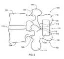
- FIG. 3is a front elevational view of the spinal implant and spinous processes of FIG. 2 , in accordance with an aspect of the present invention
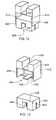
- FIG. 4is a front elevational view of a spinal implant, in accordance with an aspect of the present invention.
- FIG. 5is a front cross-sectional view of the implant of FIG. 4 , with an extending fork thereof located in a cavity thereof, in accordance with an aspect of the present invention
- FIG. 6is a front cross-sectional view of the implant of FIG. 4 , with the extending fork protruding from the cavity, in accordance with an aspect of the present invention
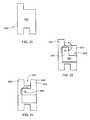
- FIG. 7is a perspective view of a spinal implant, in accordance with an aspect of the present invention.
- FIG. 8is a front cross-sectional view of the implant of FIG. 7 , in accordance with an aspect of the present invention.
- FIG. 9is a front elevational view of the implant of FIG. 7 , in accordance with an aspect of the present invention.
- FIG. 10is a front elevational view of an implant in a non-use position, in accordance with an aspect of the present invention.
- FIG. 11is a front elevational view of the implant of FIG. 10 in an in-use position, in accordance with an aspect of the present invention.
- FIG. 12is a front cross-sectional view of the implant of FIG. 10 , in accordance with an aspect of the present invention.
- FIG. 13is an exploded cross-sectional view of the implant of FIG. 10 , in accordance with an aspect of the present invention.
- FIG. 14is a front perspective view of an implant in an in-use position, in accordance with an aspect of the present invention.
- FIG. 15is a front cross-sectional view of the implant of FIG. 14 , in accordance with an aspect of the present invention.
- FIG. 16is a front cross-sectional view of the implant of FIG. 14 in a non-use position, in accordance with an aspect of the present invention
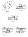
- FIG. 17is a perspective view of a spinal implant, in accordance with an aspect of the present invention.
- FIG. 18is a front cross-sectional view of the implant of FIG. 17 , in accordance with an aspect of the present invention.
- FIG. 19is a front elevational view of a spinal implant in a non-use position, in accordance with an aspect of the present invention.
- FIG. 20is a front cross-sectional view of the implant of FIG. 19 , in accordance with an aspect of the present invention.
- FIG. 21is a front elevational view of the implant of FIG. 19 in an in-use position, in accordance with an aspect of the present invention.
- FIG. 21Ais a front elevational view of a spinal implant in a non-use position, in accordance with an aspect of the present invention.
- FIG. 22is a front elevational view of a spinal implant, in accordance with an aspect of the present invention.
- FIG. 23is a front cross-sectional view of the implant of FIG. 22 , in accordance with an aspect of the present invention.
- FIG. 24is a front cross-sectional view of the implant of FIG. 22 in an in-use position, in accordance with an aspect of the present invention.
- FIG. 25is a front elevational view of a spinal implant in a non-use position, in accordance with an aspect of the present invention.
- FIG. 26is a front elevational view of the implant of FIG. 25 in an in-use position, in accordance with an aspect of the present invention.
- FIG. 27is a front elevational view of an implant in a non-use position, in accordance with an aspect of the present invention.
- FIG. 28is a side elevational view of the implant of FIG. 27 , in accordance with an aspect of the present invention.
- FIG. 29is a front elevational view of the implant of FIG. 27 in an in-use position, in accordance with an aspect of the present invention.
- FIG. 29Ais a front elevational view of the implant of FIG. 27 in an in-use position, in accordance with an aspect of the present invention.
- FIG. 29Bis a front perspective view of the spinal implant of FIG. 29A in a non-use position, in accordance with an aspect of the present invention
- FIG. 30is a front elevational view of a spinal implant in a non-use position, in accordance with an aspect of the present invention.
- FIG. 31is a front elevational view of the implant of FIG. 30 in an in-use position, in accordance with an aspect of the present invention.
- FIG. 32is a front elevational view of a spinal implant in a non-use position, in accordance with an aspect of the present invention.
- FIG. 32Ais a front elevational view of a spinal implant in an in-use position, in accordance with an aspect of the present invention.
- FIG. 32Bis a front elevational view of a spinal implant in a non-use position, in accordance with an aspect of the present invention.
- FIG. 33is a perspective view of a spinal implant, in accordance with an aspect of the present invention.
- FIG. 34is a side cross-sectional view of the implant of FIG. 33 in a non-use position, in accordance with an aspect of the present invention.
- FIG. 35is a side cross-sectional view of the implant of FIG. 33 in an in-use position, in accordance with an aspect of the present invention.
- FIG. 36is a top cross-sectional view of a spinal implant in a non-use position, in accordance with an aspect of the present invention.
- FIG. 37is a top cross-sectional view of the implant of FIG. 36 in an in-use position, in accordance with an aspect of the present invention.
- FIG. 38is a top cross-sectional view of a spinal implant in a non-use position, in accordance with an aspect of the present invention.
- FIG. 39is a top cross-sectional view of the implant of FIG. 38 in an in-use position, in accordance with an aspect of the present invention.
- FIG. 40is a top cross-sectional view of an implant in a non-use position, in accordance with an aspect of the present invention.
- FIG. 41is a top cross-sectional view of the implant of FIG. 40 in an in-use position
- FIG. 42is a perspective view of a spinal implant, in accordance with an aspect of the present invention.
- FIG. 43is a perspective view of a spinal implant, in accordance with an aspect of the present invention.
- FIG. 44is a perspective view of a spinal implant, in accordance with an aspect of the present invention.
- FIG. 45is a perspective view of a spinal implant, in accordance with an aspect of the present invention.
- spinal implant systems and methods for inserting spinal implantsare provided.
- the implants described hereinavoid some or all of the cuts to a supraspinous ligament of a patient by allowing the implants to be inserted from a side of the patient's spine, interspinous space and supraspinous ligament when the implant is configured in a non-use position.
- the in-situ implantmay then be manipulated to an in-use position by a surgeon from the same side as the insertion of the implant without damaging the supraspinous ligament.
- the implantmay be inserted, and manipulated, from a side of a mid-line of a patient's spine when viewed from a posterior thereof.
- spinal column 20includes a lumbar region 2 , a sacral region 4 , and a coccygeal region 6 .
- column 20also includes a cervical region and a thoracic region. For clarity and ease of discussion, the cervical region and the thoracic region are not illustrated.
- Lumbar region 2includes a first lumbar vertebra 8 , a second lumbar vertebra 9 , a third lumbar vertebra 12 , a fourth lumbar vertebra 14 , and a fifth lumbar vertebra 16 .
- Sacral region 4includes a sacrum 18 .
- coccygeal region 6includes a coccyx 13 .
- FIG. 2depicts a lateral view of two adjacent vertebrae, e.g., two of the lumbar vertebra 8 , 9 , 12 , 14 , 16 shown in FIG. 1 .
- FIG. 2illustrates a superior vertebra 100 and an inferior vertebra 102 with a lumbar disc 216 therebetween.
- each vertebra 100 , 102includes a vertebral body 104 , a superior articular process 116 , a transverse process 108 , a spinous process 110 and an inferior articular process 112 .
- FIG. 2further depicts an interspinous space 114 that can be established between an upper spinous process 120 and a lower spinous process 130 by the removal of the interspinous ligament and any other boney or soft tissue needed for the insertion of a spinal implant 200 .
- a spinal implant 200may be H-shaped including a core 210 and a plurality of extending forks extending away from the core.
- a first fork 220 and a second fork 230extend upwardly from core 210 , define an opening 240 to receive upper spinous process 120 , and are configured (e.g., shaped and dimensioned) to be received on opposite sides of upper spinous process 120 .
- a third fork 250 and a fourth fork 260extend downwardly away from core 210 and are configured (e.g., shaped and dimensioned) to be received on opposite sides of lower spinous process 130 .
- Core 210is configured (e.g., shaped and dimensioned) to be received between upper spinous process 120 and lower spinous process 130 and to provide support, distraction and/or separation pressure therebetween.
- core 210may maintain a space between upper spinous process 120 and lower spinous process 130 in an area between the processes where an interspinous ligament has been removed. Further, core 210 may maintain such support, distraction and/or separation pressure to remove or off load at least some pressure from articular processes 112 and 116 .
- second fork 230may be received in a cavity 270 of implant 200 when implant 200 is in a non-use position, and first fork 220 and core 210 may bound opening 240 having substantially an L-shape, prior to the insertion of implant 200 into an interspinous cavity.
- second fork 230may be extended upwardly (i.e., to an in-use position) such that second fork 230 and first fork 220 bound opening 240 (e.g., having substantially a U-shape) receiving upper spinous process 120 .
- Second fork 230may be held in place via a friction fit between an engaging portion 272 of core 210 and a corresponding engaging portion 274 of second fork 230 when second fork 230 is “snapped into” the remainder of implant 200 . Also, an extending portion 275 of fork 230 may abut a bottom side 273 of engagement portion 272 to inhibit vertical movement of fork 230 out of cavity 270 .
- second fork 230may be held in place utilizing a set screw, ratcheting mechanism, shim, spring, or any other means of holding second fork 230 in place and inhibiting separation of second fork 230 from the remainder of implant 200 . The use of set screws, ratcheting mechanisms, springs and shims are further discussed below.
- Implant 300having a first fork 330 separate from, and attachable to, a core 310 .
- Implant 300may include a cavity 305 configured (i.e., shaped and dimensioned) to receive first fork 330 .
- First fork 330may be held in place via a friction fit between walls 312 defining an internal cavity engaging portion 372 of a core 310 and a corresponding connecting portion 374 of first fork 330 when first fork 330 is “snapped into” the remainder of implant 300 .
- Connecting portion 374 and engaging portion 372may inhibit movement of fork 330 away from core 310 .
- an implant 400includes a top member 410 movably attached to a bottom member 420 .
- a top portion 426 of bottom member 420is received in a cavity 415 ( FIG. 12 ) of top member 410 .
- the cavityis configured (e.g., shaped and dimensioned) to receive bottom member 420 .
- cavity 415is defined by inner surfaces 414 of top member 410 such that the width of bottom member 420 is less than the width of inner surfaces 414 and thus cavity 415 as depicted in FIGS. 12-13 .
- top member 410 and bottom member 420may be vertically expanded relative to one another such that a minimal amount of top portion 426 of bottom member 420 is received within cavity 415 and implant 400 may be at its maximum height as depicted in FIG. 11 .
- implant 400may have its height minimized in a non-use position as depicted in FIG. 10 to allow it to be fit into an interspinous space (e.g., space 114 ) between spinous processes, and implant 400 may then be expanded or increased in height as desired, i.e., to an in-use position.
- Top member 410may be held in place via a friction fit between an engaging portion, such as inner surfaces 414 of cavity 415 , and a corresponding engaging surface, such as outer portion 422 , of bottom member 420 when top member 410 and bottom member 420 are extended to a desired height relative to one another.
- top member 410 and bottom member 420may be held in place relative to each other utilizing a set screw, ratcheting mechanism, shim, spring, or any other means of holding top member 410 and bottom member 420 at a fixed position relative to each other.
- Top member 410may also include a retaining member 450 configured to retain bottom member 420 connected to top member 410 .
- Retaining member 450may include a connecting member or rod 452 connected to opposite inner surfaces 414 of cavity 415 of top member 410 and may be received in passages 453 of bottom member 420 when bottom member 420 is received in cavity 415 .
- Rod 452may be connected to a holder 455 which is configured (e.g., shaped and dimensioned) to be received in a cavity 425 configured to receive a lower spinous process (e.g., lower spinous process 130 ).
- Retaining member 450thus allows movement of bottom member 420 into cavity 415 but inhibits movement of bottom member 420 past retaining member 450 in a direction out of the cavity by contact of holder 455 and rod 452 with upper surfaces 454 of bottom member 420 .
- top member 410 and bottom member 420may be held relative to one another without using retaining member 450 (e.g., via a friction fit, set screw, ratcheting mechanism, shim, spring, or other means of holding top and bottom members relative to each other).
- Top member 410also includes an opening 416 for receiving an upper spinous process (e.g., upper spinous process 120 ).
- an implant 500may include a core 510 having a cavity 515 configured (e.g., shaped and dimensioned) to receive a top member 520 and a bottom member 530 therein when in a non-use position.
- a cavity 515configured (e.g., shaped and dimensioned) to receive a top member 520 and a bottom member 530 therein when in a non-use position.
- top member 520 and bottom member 530may be received within cavity 515 to allow implant 500 to be inserted into an interspinous cavity such as interspinous cavity 114 ( FIG. 2 ) while minimizing damage to a supraspinous ligament.
- cavity 515is defined by inner surfaces 514 of core 510 such that the widths of top member 520 and bottom member 530 are less than the distance between inner surfaces 514 defining cavity 515 .
- top member 520 and bottom member 530may be vertically expanded relative to one another such that a minimal amount of top portion 535 of bottom member 530 and bottom portion 525 of top member 510 are received within cavity 515 and implant 500 may be at its maximum height as depicted in FIGS. 14-15 .
- implant 500may have its height minimized in a non-use position as depicted in FIG. 16 to allow it to be easily fit into the interspinous space (e.g., space 114 ) between the spinous processes and implant 500 may then be expanded or increased in height as desired, i.e., to an in-use position.
- Top member 520 and bottom member 530may be held in place relative to core 510 in an in-use or a non-use position via a friction fit between an engaging portion, such as outer surfaces 522 , of top member 520 and an engaging portion, such as outer surfaces 532 , of bottom member 530 with a corresponding engaging portion and/or inner surfaces 514 of core 510 .
- top member 520 and bottom member 530may be held in place relative to each other and core 510 utilizing a set screw, ratcheting mechanism, shim, spring or any other means of holding top member 520 and bottom member 530 relative to core 510 and each other.
- Core 510may also include a top retaining member 550 configured to retain top member 520 connected to core 510 .
- Retaining member 550may include a connecting member, such as a rod 552 , connected to opposite inner surfaces 514 of cavity 515 of core 510 and may be received in passages 553 between upper forks 527 of top member 520 when top member 520 is received in cavity 515 .
- Rod 550may be connected to a holder 555 which is configured (e.g., shaped and dimensioned) to be received in cavity 525 configured to receive an upper spinous process (e.g., upper spinous process 120 ).
- Retaining member 550thus allows movement of top member 520 into cavity 515 but inhibits movement of top member 520 past retaining member 550 in a direction out of the cavity by contact of holder 555 and rod 552 with upper surfaces 554 of top member 520 .
- a bottom retaining member 580inhibits movement of bottom member 530 away from cavity 515 by contact between bottom surfaces 585 of bottom member 530 with a holder 595 connected to inner surfaces 514 by a rod (not shown).
- top member 520 and bottom member 530may be held in place relative to core 510 in an in-use, or non-use position without utilizing top retaining member 550 or bottom retaining member 580 (e.g., via a friction fit, set screw, ratcheting mechanism, shim, spring, or other means of holding top and bottom members relative to each other).
- an implant 600includes a plurality of telescoping sections 610 .
- a first section 620has a cavity 625 which may at least partially receive a second section 630 therein.
- a third section 640may be at least partially received in a cavity 635 of second section 630 .
- a fourth section 650may be received at least partially in a cavity 645 of third section 640 .
- Each sectionmay be received in the appropriate cavity of the section connected thereto when in a non-use position, i.e. prior to insertion of implant 600 into an interspinous cavity such as interspinous cavity 114 ( FIG. 2 ). Adjacent sections may then be held relative to one another in an in-use position, as depicted for example in FIGS.
- fourth section 650may include a cavity 655 for receiving a spinous process, which is bounded by forks 657
- first section 620may include a cavity 625 for receiving an opposite spinous process, which is bounded by forks 627 .
- an implant 700may include a fork 720 rotatably attached to a core 710 .
- Fork 720may be movable (e.g., rotatable about a pin 722 ) from a first (i.e., non-use) position in which the implant includes an h-shape, as depicted in FIGS. 19 and 20 to a second (i.e., in-use) position depicted in FIG. 21 in which the implant is H-shaped.
- An internal end 723 of fork 720may be received in a cavity 712 of core 710 and cavity 712 may be formed in an arc shape to allow such rotation as depicted in FIG. 20 .
- Fork 720may have a rectilinear cross-section as depicted in the figures, for example.
- Fork 720may be located in a non-use position in the first position which may facilitate the insertion of the implant into an interspinous space such as interspinous space 114 ( FIG. 2 ).
- the offset position of fork 720 in FIGS. 19-20may allow the implant to be manipulated under or around the supraspinous ligament to avoid (or minimize) the necessity of cutting such ligament.
- fork 720 and a second fork 730may be substantially parallel to each other and may bound an opening 725 for receiving an upper spinous process such as upper spinous process 120 ( FIG. 2 ).
- Core 710 , second fork 730 , a third fork 740 , and a fourth fork 750may be formed integral (i.e., monolithic) to one another and may be substantially rigid and non-movable relative to each other.
- First fork 720may be held in an in-use position ( FIG. 21 ) and/or a non-use position ( FIG. 20 ) via a friction fit between outer surface 724 of fork 720 and an inner surface 713 of core 710 .
- first fork 720may be held in place relative to core 710 utilizing a set screw, shim, ratcheting, spring, or any means for maintaining the fork as depicted in FIG. 21 , e.g., parallel to the other forks and bounding opening 725 .
- first fork 720may be connected to core 710 via a pin or any other means for allowing the movability thereof relative to core 710 .
- an implant 1700may include a fork 1720 hingedly or otherwise rotatably connected to a core 1710 about a hinge 1722 .
- Core 1710may include an upper fork 1730 and a lower fork 1740 along with a right lower fork 1750 .
- Upper fork 1730 and fork 1720may bound an opening 1725 for receiving an upper spinous process, such as upper spinous process 120 ( FIG. 2 ).
- Lower fork 1740 and right lower fork 1750may bound a cavity 1726 for receiving a lower spinous process, such as lower spinous process 130 ( FIG. 2 ).
- FIG. 21Aan implant 1700 may include a fork 1720 hingedly or otherwise rotatably connected to a core 1710 about a hinge 1722 .
- Core 1710may include an upper fork 1730 and a lower fork 1740 along with a right lower fork 1750 .
- Upper fork 1730 and fork 1720may bound an opening 1725 for receiving an upper spinous process, such as
- fork 1720is in a non-use position while the rotation of fork 1720 in a counter-clockwise direction such that fork 1720 is substantially parallel to fork 1730 results in fork 1720 being located in an in-use position.
- fork 1720may be held in the in-use positions via a set screw, ratcheting mechanism, shim, spring, or any other means of holding fork 1720 relative to core 1710 .
- an implant 800may include a first fork 820 which is rotatable relative to a core 810 .
- First fork 820may have an L-shape and may be entirely received in a cavity 815 of core 810 when in a non-use position ( FIGS. 22-23 ).
- the position of first fork 820 entirely within the cavitymay allow the implant to be manipulated under or around the supraspinous ligament to avoid the necessity of cutting such ligament during the insertion thereof into an interspinous cavity, such as interspinous cavity 114 .
- fork 820may be rotated about a pin 822 such that an extending portion 821 of fork 820 extending outside cavity 815 is substantially parallel to a second fork 830 and the forks bound an opening 825 configured (e.g., shaped and dimensioned) to receive an upper spinous process such as upper spinous process 120 ( FIG. 2 ).
- Core 810may be received in an interspinous space such as interspinous space 114 ( FIG. 2 ).
- First fork 820may be held in place relative to core 810 via a friction fit between outer surface 824 of fork 820 and an inner surface 813 of core 810 .
- first fork 820may be held in place relative to core 810 utilizing a set screw, ratcheting mechanism, shim, spring, or any other means of holding first fork 820 relative to core 810 .
- an implant 900includes a top member 910 pivotally connected to a bottom member 920 at a hinge, pivot or pin 925 .
- a bottom side 912 of top member 910may abut a topside 922 of bottom member 920 .
- a cavity 915may be present between bottom side 912 of top member 910 and topside 922 of bottom member 920 .
- a minimal left side height 923which may be less than minimum height 926 as depicted, may further facilitate the insertion desired.
- fork top member 910 and bottom member 920may be rotated about pin 925 relative to each other from such minimum height to the maximum height.
- Top member 910 and bottom member 920may be held relative to one another in the in-use position as depicted in FIG. 26 by a shim, set screw, ratcheting mechanism, spring, or any other means of holding the members relative to one another such that they may maintain an upper spinous process (e.g. upper spinous process 120 ( FIG. 3 )) and a lower spinous process (e.g., lower spinous process 130 ( FIG. 3 )) at a desired position relative to one another.
- top member 910may include a cavity 913 for receiving a spinous process, such as upper spinous process 120 ( FIG. 3 )
- bottom member 930may include a cavity 933 for receiving an opposite spinous process, such as lower spinous process 130 ( FIG. 3 ).
- an implant 1000includes a left side or core 1010 having a top right extending fork 1020 and a bottom right extending fork 1030 rotatably connected to core 1010 at first pin 1021 and second pin 1031 , respectively.
- forks 1020 and 1030may be aligned about perpendicular to a top left fork 1040 and a bottom left fork 1050 in a non-use position.
- Top right extending fork 1020 and bottom right extending fork 1030may be rotated about the respective pins to arrive at an in-use position depicted in FIG. 29 .
- the axes of rotationmay be aligned about parallel to the horizontal central portion of the H-shape of implant 1000 as depicted in FIG. 29 .
- Top right extending fork 1020 and bottom right extending fork 1030may be separated vertically by a space 1041 and may be rounded, as depicted in FIG. 27 to allow movement of the extending forks past one another during rotation to arrive at the in-use position depicted in FIG. 29 .
- top right extending fork 1020 and top left extending fork 1040may bound a cavity 1042 for receiving a top spinous process, such as top spinous process 120 ( FIG. 3 ).
- bottom right extending fork 1030 and bottom left extending fork 1050may bound a cavity 1052 for receiving a bottom spinous process such as bottom spinous process 130 ( FIG. 3 ).
- Core 1010may provide support to such opposite spinous processes and the forks may extend vertically alongside such processes.
- Top right extending fork 1020 and bottom right extending fork 1030may be held relative to one another in the in-use position as depicted in FIG. 29 by a shim, set screw, ratcheting mechanism, spring, or any other means of holding the forks relative to one another such that they bound the cavities for receiving the spinous processes.
- an implant 1800includes a core 1810 rotatably connected to a right side 1830 about a pin 1821 .
- Right side 1830may include an upper fork 1832 and a lower fork 1834 .
- Core 1810may include an upper left fork 1820 and a lower left fork 1822 .
- Upper left fork 1820 and upper fork 1832may bound an opening 1842 for receiving an upper spinous process (e.g., upper spinous process 120 ).
- Lower left fork 1820 and lower fork 1834may bound an opening 1852 for receiving a lower spinous process (e.g., lower spinous process 130 ).
- 29Bdepicts implant 1800 in a non-use position and right side 1830 may be rotated to the in-use position depicted in FIG. 29A after insertion of implant 1800 into a desired interspinous space, such as interspinous space 114 ( FIG. 2 ).
- a desired interspinous spacesuch as interspinous space 114 ( FIG. 2 ).
- right side 1830may be found in an in-use position and/or a non-use position via a set screw, shim, ratcheting mechanism, spring or any other means of holding the fork relative to the core such that the upper and lower forks bound the cavity for receiving spinous processes.
- FIGS. 30-31depict an implant 1100 similar to implant 700 with the additional feature of a tether attached thereto.
- H-shaped implant 1100may include a fork 1120 rotatably attached to a core 1110 .
- Fork 1120may be movable (e.g., rotatable about a pin 1122 ) from a first position as depicted in FIG. 30 to a second position depicted in FIG. 31 .
- An internal end 1123 of fork 1120may be received in a cavity 1112 of core 1110 and cavity 1112 may be formed in an arc shape to allow such rotation as depicted in phantom in FIG. 31 .
- Fork 1120may have a rectilinear cross-section, for example, as depicted in the figures.
- Fork 1120may be located in a non-use position in the first position ( FIG. 30 ) which may facilitate the insertion of the implant into an interspinous space such as interspinous space 114 ( FIG. 2 ).
- the offset position of fork 1120 in FIG. 30may allow the implant to be manipulated under or around the supraspinous ligament to avoid the necessity of cutting such ligament.
- fork 1120 and a second fork 1130may be substantially parallel to each other and may bound an opening 1125 for receiving an upper spinous process such as upper spinous process 120 .
- Core 1110 , a second fork 1130 , a third fork 1140 , and a fourth fork 1150may be formed integral (i.e., monolithic) to one another and may be substantially rigid and non-movable relative to each other.
- First fork 1120has a first tether 1160 attached thereto and second fork 1130 has a second tether 1170 attached thereto.
- First fork 1120may be held in an in-use position via the attaching of first tether 1160 to second tether 1170 around upper spinous process 120 . Further, first fork 1120 may be connected to core 1110 via pin 1122 described above, or any other means for allowing movability thereof relative to core 1110 .
- the attaching of the tethers to one another as depicted in FIG. 31 such that the processes are held in place relative to the implant and vice versaallows the flexion of the spinous processes relative to one another as the tethers hold the processes relative to the implant.
- the use of the tethersmay allow a patient having an implant inserted between processes of the spine to have further support while leaning forward and may also maintain an upper and lower spinous process at a desired distance relative to one another.
- the tethersmay be attached to the implant or they may be formed integral thereto.
- the tethersmay be received in cavities or slots within the implants and ends of the tethers may be attached to one another to support the implants relative to the spinous processes and/or maintain the implants in a desired position relative to the processes.
- the tetherscould be integral (e.g., monolithic) relative to the implant.
- the tethersmay be overmolded in the mold of the implant when the implant itself is formed.
- an implant 1200may include a first fork 1210 along with a first tether 1220 and a second tether 1230 .
- the implantmay be inserted into an interspinous space and the tethers may be attached to each other around upper spinous process 120 similar to tethers 1160 and 1170 in FIGS. 30-31 without the use of a second fork opposite first fork 1210 .
- First tether 1220 and second tether 1230may be received in a cavity 1240 of implant 1200 or may be otherwise attached thereto.
- Implant 1200may be inserted under or around the supraspinous ligament to avoid damaging the ligament, as described above for the other implants. The tethers may then be attached to one another to inhibit movement of the implant.
- an implant 1900may include a core 1910 having a first tether 1920 and a second tether 1930 .
- the tethersmay be attached on opposite sides of the core 1910 .
- Each of the tethersmay wrap around opposite sides of the core and appropriate spinous processes to connect with one another.
- core 1930may be attached to a left side of core 1910 and may go along side a top left fork 1932 and may abut upper spinous process 1920 and may connect to tether 1920 at or near where tether 1920 is attached to core 1910 .
- tether 1920may travel downwardly around lower spinous process 130 and the lower extending forks of core 1910 to connect to a left side of core 1910 at or near a point where tether 1930 is attached to core 1910 .
- the tethersmay be attached to core 1910 in any number of ways such as being formed integral (e.g., monolithic) thereto, being received in slots or cavities (not shown) thereof or via screws. Further, the tethers may be attached to each other by being tied to one another, for example.
- an implant 2000may include a core 2010 and may have a first tether 2020 received in a cavity 2015 thereof. Also, a second tether 2030 may be received in a second cavity 2035 . In another example, the tethers could be received in the same cavity or the tethers could be formed integral (e.g., overmolded with) relative to core 2010 . Similar to the depiction in FIG. 32A , opposite ends of the tethers may be attached to each other to secure them to the appropriate spinous process when core 2010 is received in an interspinous space, such as interspinous space 114 .
- implant 200may include a threaded boss 201 aligned in a width direction of the implant for receiving a set screw 202 to hold second fork 230 in position.
- FIG. 34depicts a side cross-sectional view of a non-use position also depicted in FIG. 5
- FIG. 35depicts a side view of an in-use position as also depicted in FIG. 4 .
- Set screw 202may be threaded into boss 201 to maintain second fork 230 in such non-use or in-use position.
- a bore 203configured (e.g., shaped and dimensioned) to receive the set screw may be aligned in a direction transverse to a height of implant 200 and in a lengthwise direction relative to the implant.
- Such a set screwmay hold second fork 230 in a non-use in FIG. 36 and an in-use position in FIG. 37 .
- FIGS. 38-39depict an H-shaped implant 1300 similar to implant 200 ( FIGS. 4-6 ) having a fork 1310 which is receivable in a cavity 1315 .
- a ratchet mechanism 1320is received in the cavity and is engageable with teeth 1317 on a side 1319 of fork 1310 such that ratchet 1320 engages with teeth 1317 to maintain fork 1310 in a particular position by inhibiting backward movement toward a core 1322 of implant 1300 .
- FIG. 38depicts a non-use position and FIG. 39 depicts an in-use position.
- FIGS. 40-41depict a ratchet utilized with an implant 1340 which is similar to implant 700 depicted in FIGS. 19-21 .
- a ratchet 1350engages teeth 1355 of a fork 1342 .
- ratchet 1350moves along teeth 1355 and retains fork 1342 in a particular position (i.e. by inhibiting backward rotation) according to the rotation of fork 1342 from the non-use position to the in-use position.
- FIGS. 42-45depict the use of a shim with the embodiments similar or identical to those depicted in FIGS. 4-6 , 10 - 16 , and 22 - 24 .
- a shim 1370may be received in an implant 1400 similar to implant 200 ( FIGS. 4-6 ) except for an opening 1414 on a front side thereof to allow insertion of shim 1370 to maintain fork 1330 , which is similar to fork 230 , in an in-use position as depicted in FIG. 42 .
- implant 800also depicted in FIGS.
- FIG. 44depicts implant 1500 , which is similar to implant 400 depicted in FIGS. 10-12 except for an opening 1514 in a front side thereof to allow shim 1550 to be received in a cavity 1515 .
- Shim 1550may hold upper member 1510 in an in-use position as depicted in FIG. 44 similar to implant 400 depicted in FIG. 10 .
- FIG. 45depicts implant 1600 receiving a shim 1650 through an opening 1614 in a cavity 1615 .
- Implant 1600is similar to implant 500 except for opening 1614 in a front side of implant 1600 to allow the shim to be inserted therein.
- shim 1650may maintain top member 1620 and bottom member 1630 separated from one another such that an upper spinous process may be received in cavity 1625 and a lower spinous process may be received in cavity 1635 of top member 1620 and bottom member 1630 .
- the embodiments depictedinclude openings for receiving shims, which are located in particular positions, the openings could be located in various positions on the implant, such as a top, bottom or the side(s) thereof.
- the forks and top and bottom members described above, which are movable between in-use and non-positionsmay be maintained in such in-use and/or non-use positions utilizing a spring or other biasing mechanism which may bias the implant in the in-use or non-use position.
- a spring or other biasing mechanismwhich may bias the implant in the in-use or non-use position.
- the shims depicted in FIGS. 43-45could be replaced by a spring which biases the forks toward an in-use position configured to bound upper and lower spinous processes.
- a biasing mechanismsuch as a spring
- a set screw or other meansmay be utilized to hold the implant in the non-use position prior to its insertion into the interspinous space.
- the implants describedcould be formed of various materials which are biocompatible and which may maintain the spinous processes relative to one another in desired positions.
- the described implants and portions thereofmay be formed of rigid materials (e.g., metal, such as titanium, or stiff polymers), semi rigid materials (e.g. PEEK, a less stiff plastic or silicone), or a substantially flexible material (e.g., silicone or flexible plastic).
- the implant described hereincould have a modulus of elasticity substantially equal to a modulus of elasticity of bone, particularly the bone forming the spinous processes which the implants support.
- the implants described hereincould be formed of any shape (e.g., H-shaped, h-shaped, and n-shaped) such that the implants may be received between upper and lower spinous processes to support the spinous process and/or provide flexion or restraint to such spinous processes.
- the implantscould be loaded and manipulated from a non-use position to an in-use position from one side of the interspinous space (e.g., from a side of a mid-line of a spine of a patient).
- a portion of an implantcould be inserted from one side of a mid-line of the spine (e.g., one side of the interspinous space) while a second portion of the implant could be inserted from the other side thereof.
- the forks, cores, top portions, bottom portions and other portions of the spinal implants described hereincould be formed in any shape which facilitates their insertion into an interspinous space between spinous processes and allows the implant to support and/or separate the processes as desired.
Landscapes
- Health & Medical Sciences (AREA)
- Orthopedic Medicine & Surgery (AREA)
- Life Sciences & Earth Sciences (AREA)
- Neurology (AREA)
- Surgery (AREA)
- Heart & Thoracic Surgery (AREA)
- Engineering & Computer Science (AREA)
- Biomedical Technology (AREA)
- Nuclear Medicine, Radiotherapy & Molecular Imaging (AREA)
- Medical Informatics (AREA)
- Molecular Biology (AREA)
- Animal Behavior & Ethology (AREA)
- General Health & Medical Sciences (AREA)
- Public Health (AREA)
- Veterinary Medicine (AREA)
- Prostheses (AREA)
Abstract
Description
The present invention relates generally to the field of surgery and medical implants, and more particularly, to spinal implant systems and methods for inserting spinal implant systems.
The human spine is a biomechanical structure with thirty-three vertebral members, and is responsible for protecting the spinal cord, nerve roots and internal organs of the thorax and abdomen. The spine also provides structural support for the body while permitting flexibility of motion. A significant portion of the population will experience back pain at some point in their lives resulting from a spinal condition. The pain may range from general discomfort to disabling pain that immobilizes the individual. Back pain may result from a trauma to the spine, be caused by the natural aging process, or may be the result of a degenerative disease or condition.
Procedures to remedy back problems sometimes require correcting the distance between vertebral members by inserting an intervertebral device (e.g., spacer) between the members. Dynamic interspinous spacers are currently used to treat patients with a variety of indications. Essentially, these patients present a need for distraction of the posterior elements (e.g., the spinous processes) of the spine using a mechanical device. Current clinical indications for such a device may include stenosis, disc herniation, facet arthropathy, degenerative disc disease and adjacent segment degeneration.
Currently, marketed interspinous devices include rigid and flexible spacers made from PEEK, titanium, silicone or some combination of other implantable materials. However, these devices require an open technique to be implanted, and many require destroying important anatomical stabilizers, such as the supraspinous ligament. In particular, the current technique for placing such spacers between the interspinous processes is to cut the interspinous and supraspinous ligaments and slide the device over the adjacent spinous processes.
Thus, a need exists for improved spinal implant systems and methods for implanting such systems which are minimally invasive and minimally destructive of important anatomical stabilizers. The systems and methods disclosed herein address this need.
The shortcomings of the prior art are overcome and additional advantages are provided in one aspect through an interspinous spacer system which includes a core shaped and configured to fit in an interspinous space between adjacent spinous processes. A plurality of extending forks extends from the core and has shapes configured to extend along the vertical sides of the spinous processes. A first fork of the plurality of forks is moveable relative to the core from a non-use position to an in-use position. The first fork is located on a first side of the core when in the in-use position and has a first inner side bounding an opening for receiving a first spinous process of the spinous processes. The first fork is substantially non-flexible. A second fork is located on the first side of the core and the second fork has a second inner side bounding the opening for receiving the first spinous process of the spinous processes. The second fork is immovable relative to the core. The first fork avoids protruding from the core such that the first fork bounds the opening in the non-use position to allow the core to be inserted into the interspinous space in the non-use position to avoid damage to a supraspinous ligament adjacent the space.
The present invention provides, in a further aspect, an interspinous spacer system which includes a core having a shape configured to fit between adjacent spinous processes. A plurality of extending forks extends from the core and has shapes configured to extend along vertical sides of the spinous processes. A first fork and second fork of the plurality of forks are coupled to the core and moveable from a non-use position to an in-use position. The first fork and the second fork define an opening for receiving a first spinous process of the spinous processes when in an in-use position. The core includes a cavity defined by inner surfaces of the core and the cavity includes a cavity width between the inner surfaces of the core defining the cavity. A distance between opposite longitudinal outermost surfaces of the first fork and the second fork is less than the cavity width to allow the first fork and the second fork to be received in the cavity in the non-use position to avoid damaging a supraspinous process adjacent the space.
The present invention provides, in yet another aspect, a method for spacing adjacent spinous processes which includes providing an interspinous spacer having a non-use position and an in-use position. The spacer includes a core and a plurality of extending of forks extending from the core and having shapes configured to extend along vertical sides of the spinous processes. The plurality of forks includes a first fork and a second fork. The first fork avoids protruding from the core such that the first fork avoids bounding an opening for receiving the first spinous process of the spinous processes in the non-use position. The first fork is substantially non-flexible. The second fork is located on a first side of the core and has an inner side bounding the opening for receiving the first spinous process of the spinous processes and is immovable relative to the core. The core is inserted, when the interspinous spacer is in the non-use position, into a space between the spinous processes from a side of a mid-line of a spine of a patient to avoid damaging a supraspinous ligament adjacent the space. The first fork is moved from the non-use position to the in-use position such that the first fork is located on the first side of the core. The fork has a first inner side bounding the opening for receiving the first spinous process of the spinous processes in the in-use position.
The present invention provides, in yet a further aspect, a method for spacing adjacent spinous processes which includes providing an interspinous spacer having a non-use position and an in-use position. The spacer includes a core and a plurality of extending forks extending from the core having shapes configured to extend along vertical sides of the spinous processes. The core is inserted, when the spacer is in the non-use position, into a space between the spinous processes from a side of a mid-line of a spine of a patient to avoid damaging a supraspinous ligament adjacent the space. The spacer is moved from the non-use position to the in-use position such that a first fork and a second fork of the plurality of forks coupled to the core define an opening receiving a first spinous process of the spinous processes in the in-use position. The moving includes extending the first fork and the second fork from a cavity of the core with the cavity being defined by inner surfaces of the core. The cavity has a cavity width between the inner surfaces. A distance between opposite longitudinal outer most surfaces of the first fork and the second fork is less than the cavity width to allow the first fork and the second fork to be received in the cavity in the non-use position.
Further, additional features and advantages are realized through the techniques of the present invention. Other embodiments and aspects of the invention are described in detail herein and are considered a part of the claimed invention.
The subject matter, which is regarded as the invention, is particularly pointed out and distinctly claimed in the claims at the conclusion of the specification. The foregoing and other objects, features, and advantages of the invention will be apparent from the following detailed description of preferred embodiments taken in conjunction with the accompanying drawings in which:
In accordance with the principles of the present invention, spinal implant systems and methods for inserting spinal implants are provided. The implants described herein avoid some or all of the cuts to a supraspinous ligament of a patient by allowing the implants to be inserted from a side of the patient's spine, interspinous space and supraspinous ligament when the implant is configured in a non-use position. The in-situ implant may then be manipulated to an in-use position by a surgeon from the same side as the insertion of the implant without damaging the supraspinous ligament. For example, the implant may be inserted, and manipulated, from a side of a mid-line of a patient's spine when viewed from a posterior thereof.
Referring toFIG. 1 , a portion of aspinal column 20 is shown. As depicted,spinal column 20 includes alumbar region 2, asacral region 4, and a coccygeal region6. As is known in the art,column 20 also includes a cervical region and a thoracic region. For clarity and ease of discussion, the cervical region and the thoracic region are not illustrated.Lumbar region 2 includes a firstlumbar vertebra 8, a secondlumbar vertebra 9, a thirdlumbar vertebra 12, a fourthlumbar vertebra 14, and a fifthlumbar vertebra 16.Sacral region 4 includes asacrum 18. Further, coccygeal region6 includes acoccyx 13.
As depicted inFIG. 1 , a first intervertebrallumbar disc 22 is disposed between firstlumbar vertebra 8 and secondlumbar vertebra 9. A second intervertebrallumbar disc 24 is disposed between secondlumbar vertebra 9 and thirdlumbar vertebra 12. A third intervertebrallumbar disc 26 is disposed between thirdlumbar vertebra 12 and fourthlumbar vertebra 14. Further, a fourth intervertebrallumbar disc 28 is disposed between fourthlumbar vertebra 14 and fifthlumbar vertebra 16. Additionally, a fifth intervertebrallumbar disc 30 is disposed between fifthlumbar vertebra 16 andsacrum 18.
As depicted inFIG. 3 , aspinal implant 200 may be H-shaped including acore 210 and a plurality of extending forks extending away from the core. Afirst fork 220 and asecond fork 230 extend upwardly fromcore 210, define anopening 240 to receive upperspinous process 120, and are configured (e.g., shaped and dimensioned) to be received on opposite sides of upperspinous process 120. Athird fork 250 and afourth fork 260 extend downwardly away fromcore 210 and are configured (e.g., shaped and dimensioned) to be received on opposite sides of lowerspinous process 130.Core 210 is configured (e.g., shaped and dimensioned) to be received between upperspinous process 120 and lowerspinous process 130 and to provide support, distraction and/or separation pressure therebetween. For example,core 210 may maintain a space between upperspinous process 120 and lowerspinous process 130 in an area between the processes where an interspinous ligament has been removed. Further,core 210 may maintain such support, distraction and/or separation pressure to remove or off load at least some pressure fromarticular processes
As depicted inFIGS. 4-6 ,second fork 230 may be received in acavity 270 ofimplant 200 whenimplant 200 is in a non-use position, andfirst fork 220 andcore 210 may bound opening240 having substantially an L-shape, prior to the insertion ofimplant 200 into an interspinous cavity. After such insertion,second fork 230 may be extended upwardly (i.e., to an in-use position) such thatsecond fork 230 andfirst fork 220 bound opening240 (e.g., having substantially a U-shape) receiving upperspinous process 120.Second fork 230 may be held in place via a friction fit between anengaging portion 272 ofcore 210 and a correspondingengaging portion 274 ofsecond fork 230 whensecond fork 230 is “snapped into” the remainder ofimplant 200. Also, an extendingportion 275 offork 230 may abut abottom side 273 ofengagement portion 272 to inhibit vertical movement offork 230 out ofcavity 270. Alternatively,second fork 230 may be held in place utilizing a set screw, ratcheting mechanism, shim, spring, or any other means of holdingsecond fork 230 in place and inhibiting separation ofsecond fork 230 from the remainder ofimplant 200. The use of set screws, ratcheting mechanisms, springs and shims are further discussed below.
As depicted inFIGS. 7-9 , another example includes animplant 300 having afirst fork 330 separate from, and attachable to, acore 310.Implant 300 may include acavity 305 configured (i.e., shaped and dimensioned) to receivefirst fork 330.First fork 330 may be held in place via a friction fit betweenwalls 312 defining an internalcavity engaging portion 372 of acore 310 and a corresponding connectingportion 374 offirst fork 330 whenfirst fork 330 is “snapped into” the remainder ofimplant 300. Connectingportion 374 and engagingportion 372 may inhibit movement offork 330 away fromcore 310. In one example,first fork 330 and/orcore 310 may be sufficiently flexible to allow the insertion of connectingportion 374 into engagingportion 372 such that friction therebetween inhibits separation after they are connected. Alternatively,first fork 330 may be held in place utilizing a set screw, ratcheting mechanism, shim, spring, or any other means of holdingfirst fork 330 in place.
As depicted inFIGS. 10-13 in a further example, animplant 400 includes atop member 410 movably attached to abottom member 420. In a non-use position depicted inFIG. 10 , atop portion 426 ofbottom member 420 is received in a cavity415 (FIG. 12 ) oftop member 410. The cavity is configured (e.g., shaped and dimensioned) to receivebottom member 420. For example,cavity 415 is defined byinner surfaces 414 oftop member 410 such that the width ofbottom member 420 is less than the width ofinner surfaces 414 and thuscavity 415 as depicted inFIGS. 12-13 . When inuse top member 410 andbottom member 420 may be vertically expanded relative to one another such that a minimal amount oftop portion 426 ofbottom member 420 is received withincavity 415 andimplant 400 may be at its maximum height as depicted inFIG. 11 . Thus,implant 400 may have its height minimized in a non-use position as depicted inFIG. 10 to allow it to be fit into an interspinous space (e.g., space114) between spinous processes, andimplant 400 may then be expanded or increased in height as desired, i.e., to an in-use position.
In another example depicted inFIGS. 14-16 , animplant 500 may include acore 510 having acavity 515 configured (e.g., shaped and dimensioned) to receive atop member 520 and abottom member 530 therein when in a non-use position. For example, in the non-use position depicted inFIG. 16 ,top member 520 andbottom member 530 may be received withincavity 515 to allowimplant 500 to be inserted into an interspinous cavity such as interspinous cavity114 (FIG. 2 ) while minimizing damage to a supraspinous ligament. After insertion into such an interspinous cavity,top member 520 andbottom member 530 may be vertically separated from one another (e.g., using a spring or other biasing mechanism) as depicted inFIGS. 14-15 . In this position, an upper spinous process (e.g., upper spinous process120 (FIG. 3 )) may be received in an upperspinous cavity 525 betweenupper forks 527 and a lower spinous process (e.g., lower spinous process130 (FIG. 3 )) may be received in a lowerspinous cavity 535 betweenlower forks 537.
For example,cavity 515 is defined byinner surfaces 514 ofcore 510 such that the widths oftop member 520 andbottom member 530 are less than the distance betweeninner surfaces 514 definingcavity 515. When inuse top member 520 andbottom member 530 may be vertically expanded relative to one another such that a minimal amount oftop portion 535 ofbottom member 530 andbottom portion 525 oftop member 510 are received withincavity 515 andimplant 500 may be at its maximum height as depicted inFIGS. 14-15 . Thus,implant 500 may have its height minimized in a non-use position as depicted inFIG. 16 to allow it to be easily fit into the interspinous space (e.g., space114) between the spinous processes andimplant 500 may then be expanded or increased in height as desired, i.e., to an in-use position.
In another example depicted inFIGS. 17-18 , animplant 600 includes a plurality oftelescoping sections 610. Afirst section 620 has acavity 625 which may at least partially receive asecond section 630 therein. Athird section 640 may be at least partially received in acavity 635 ofsecond section 630. Afourth section 650 may be received at least partially in acavity 645 ofthird section 640. Each section may be received in the appropriate cavity of the section connected thereto when in a non-use position, i.e. prior to insertion ofimplant 600 into an interspinous cavity such as interspinous cavity114 (FIG. 2 ). Adjacent sections may then be held relative to one another in an in-use position, as depicted for example inFIGS. 17-18 , by a friction fit, set screw, ratcheting mechanism, spring(s), or any other means of holding the sections relative to one another such that they may maintain an upper spinous process (e.g. upper spinous process120 (FIG. 2 )) and a lower spinous process (lower spinous process130 (FIG. 2 )) at a desired position relative to one another. As depicted,fourth section 650 may include acavity 655 for receiving a spinous process, which is bounded byforks 657, andfirst section 620 may include acavity 625 for receiving an opposite spinous process, which is bounded byforks 627.
As depicted inFIGS. 19-21 , animplant 700 may include afork 720 rotatably attached to acore 710.Fork 720 may be movable (e.g., rotatable about a pin722) from a first (i.e., non-use) position in which the implant includes an h-shape, as depicted inFIGS. 19 and 20 to a second (i.e., in-use) position depicted inFIG. 21 in which the implant is H-shaped. Aninternal end 723 offork 720 may be received in acavity 712 ofcore 710 andcavity 712 may be formed in an arc shape to allow such rotation as depicted inFIG. 20 .Fork 720 may have a rectilinear cross-section as depicted in the figures, for example.
In another example depicted inFIG. 21A , animplant 1700 may include afork 1720 hingedly or otherwise rotatably connected to acore 1710 about ahinge 1722.Core 1710 may include anupper fork 1730 and alower fork 1740 along with a rightlower fork 1750.Upper fork 1730 andfork 1720 may bound anopening 1725 for receiving an upper spinous process, such as upper spinous process120 (FIG. 2 ).Lower fork 1740 and rightlower fork 1750 may bound acavity 1726 for receiving a lower spinous process, such as lower spinous process130 (FIG. 2 ). As depicted inFIG. 21A ,fork 1720 is in a non-use position while the rotation offork 1720 in a counter-clockwise direction such thatfork 1720 is substantially parallel to fork1730 results infork 1720 being located in an in-use position. As described for the other implants,fork 1720 may be held in the in-use positions via a set screw, ratcheting mechanism, shim, spring, or any other means of holdingfork 1720 relative tocore 1710.
As depicted inFIGS. 22-24 in another example, animplant 800 may include afirst fork 820 which is rotatable relative to acore 810.First fork 820 may have an L-shape and may be entirely received in acavity 815 ofcore 810 when in a non-use position (FIGS. 22-23 ). The position offirst fork 820 entirely within the cavity may allow the implant to be manipulated under or around the supraspinous ligament to avoid the necessity of cutting such ligament during the insertion thereof into an interspinous cavity, such asinterspinous cavity 114. To arrive at an in-use position from the non-use position,fork 820 may be rotated about apin 822 such that an extendingportion 821 offork 820 extending outsidecavity 815 is substantially parallel to asecond fork 830 and the forks bound anopening 825 configured (e.g., shaped and dimensioned) to receive an upper spinous process such as upper spinous process120 (FIG. 2 ).Core 810 may be received in an interspinous space such as interspinous space114 (FIG. 2 ).First fork 820 may be held in place relative tocore 810 via a friction fit betweenouter surface 824 offork 820 and aninner surface 813 ofcore 810. Alternatively,first fork 820 may be held in place relative tocore 810 utilizing a set screw, ratcheting mechanism, shim, spring, or any other means of holdingfirst fork 820 relative tocore 810.
In a further example depicted inFIGS. 25-26 , animplant 900 includes atop member 910 pivotally connected to abottom member 920 at a hinge, pivot orpin 925. In a non-use position depicted inFIG. 25 , abottom side 912 oftop member 910 may abut atopside 922 ofbottom member 920. In an in-use position depicted inFIG. 26 , acavity 915 may be present betweenbottom side 912 oftop member 910 andtopside 922 ofbottom member 920. The compact nature of the non-use position depicted inFIG. 25 may allow the implant to be manipulated under or around the supraspinous ligament to avoid the necessity of cutting such ligament during the insertion thereof into a interspinous cavity, such asinterspinous cavity 114. Such insertion may be facilitated by the difference in height between aminimum height 926 and a maximum height924 ofimplant 900. In the non-use position a minimalleft side height 923, which may be less thanminimum height 926 as depicted, may further facilitate the insertion desired. To arrive at the in-use position from the non-use position, forktop member 910 andbottom member 920 may be rotated aboutpin 925 relative to each other from such minimum height to the maximum height.
In yet another example depicted inFIGS. 27-29 , an implant1000 includes a left side orcore 1010 having a topright extending fork 1020 and a bottomright extending fork 1030 rotatably connected tocore 1010 atfirst pin 1021 andsecond pin 1031, respectively. As depicted inFIGS. 27-28 ,forks left fork 1040 and a bottomleft fork 1050 in a non-use position. Topright extending fork 1020 and bottomright extending fork 1030 may be rotated about the respective pins to arrive at an in-use position depicted inFIG. 29 . The axes of rotation may be aligned about parallel to the horizontal central portion of the H-shape of implant1000 as depicted inFIG. 29 . Topright extending fork 1020 and bottomright extending fork 1030 may be separated vertically by aspace 1041 and may be rounded, as depicted inFIG. 27 to allow movement of the extending forks past one another during rotation to arrive at the in-use position depicted inFIG. 29 . When in such in-use position, topright extending fork 1020 and topleft extending fork 1040 may bound acavity 1042 for receiving a top spinous process, such as top spinous process120 (FIG. 3 ). Also, bottomright extending fork 1030 and bottomleft extending fork 1050 may bound acavity 1052 for receiving a bottom spinous process such as bottom spinous process130 (FIG. 3 ).Core 1010 may provide support to such opposite spinous processes and the forks may extend vertically alongside such processes. Topright extending fork 1020 and bottomright extending fork 1030 may be held relative to one another in the in-use position as depicted inFIG. 29 by a shim, set screw, ratcheting mechanism, spring, or any other means of holding the forks relative to one another such that they bound the cavities for receiving the spinous processes.
In another example depicted inFIGS. 29A-29B , an implant1800 includes acore 1810 rotatably connected to aright side 1830 about apin 1821.Right side 1830 may include anupper fork 1832 and alower fork 1834.Core 1810 may include an upperleft fork 1820 and a lowerleft fork 1822. Upperleft fork 1820 andupper fork 1832 may bound anopening 1842 for receiving an upper spinous process (e.g., upper spinous process120). Lowerleft fork 1820 andlower fork 1834 may bound anopening 1852 for receiving a lower spinous process (e.g., lower spinous process130).FIG. 29B depicts implant1800 in a non-use position andright side 1830 may be rotated to the in-use position depicted inFIG. 29A after insertion of implant1800 into a desired interspinous space, such as interspinous space114 (FIG. 2 ). As noted relative to the other implants,right side 1830 may be found in an in-use position and/or a non-use position via a set screw, shim, ratcheting mechanism, spring or any other means of holding the fork relative to the core such that the upper and lower forks bound the cavity for receiving spinous processes.
In another example,FIGS. 30-31 depict animplant 1100 similar toimplant 700 with the additional feature of a tether attached thereto. H-shapedimplant 1100 may include afork 1120 rotatably attached to acore 1110.Fork 1120 may be movable (e.g., rotatable about a pin1122) from a first position as depicted inFIG. 30 to a second position depicted inFIG. 31 . Aninternal end 1123 offork 1120 may be received in acavity 1112 ofcore 1110 andcavity 1112 may be formed in an arc shape to allow such rotation as depicted in phantom inFIG. 31 .Fork 1120 may have a rectilinear cross-section, for example, as depicted in the figures.
Further, the tethers (e.g., tethers1160,1170) depicted may be attached to the implant or they may be formed integral thereto. For example, the tethers may be received in cavities or slots within the implants and ends of the tethers may be attached to one another to support the implants relative to the spinous processes and/or maintain the implants in a desired position relative to the processes. The tethers could be integral (e.g., monolithic) relative to the implant. For example, the tethers may be overmolded in the mold of the implant when the implant itself is formed.
As depicted inFIG. 32 , animplant 1200 may include afirst fork 1210 along with afirst tether 1220 and asecond tether 1230. The implant may be inserted into an interspinous space and the tethers may be attached to each other around upperspinous process 120 similar totethers FIGS. 30-31 without the use of a second fork oppositefirst fork 1210.First tether 1220 andsecond tether 1230 may be received in acavity 1240 ofimplant 1200 or may be otherwise attached thereto.Implant 1200 may be inserted under or around the supraspinous ligament to avoid damaging the ligament, as described above for the other implants. The tethers may then be attached to one another to inhibit movement of the implant.
In another example depicted inFIG. 32A , an implant1900 may include acore 1910 having afirst tether 1920 and asecond tether 1930. The tethers may be attached on opposite sides of thecore 1910. Each of the tethers may wrap around opposite sides of the core and appropriate spinous processes to connect with one another. For example,core 1930 may be attached to a left side ofcore 1910 and may go along side a topleft fork 1932 and may abut upperspinous process 1920 and may connect to tether1920 at or near wheretether 1920 is attached tocore 1910. Similarly,tether 1920 may travel downwardly around lowerspinous process 130 and the lower extending forks ofcore 1910 to connect to a left side ofcore 1910 at or near a point wheretether 1930 is attached tocore 1910. The tethers may be attached tocore 1910 in any number of ways such as being formed integral (e.g., monolithic) thereto, being received in slots or cavities (not shown) thereof or via screws. Further, the tethers may be attached to each other by being tied to one another, for example.
In another example depicted inFIG. 32B , animplant 2000 may include acore 2010 and may have afirst tether 2020 received in acavity 2015 thereof. Also, asecond tether 2030 may be received in asecond cavity 2035. In another example, the tethers could be received in the same cavity or the tethers could be formed integral (e.g., overmolded with) relative tocore 2010. Similar to the depiction inFIG. 32A , opposite ends of the tethers may be attached to each other to secure them to the appropriate spinous process whencore 2010 is received in an interspinous space, such asinterspinous space 114.
As described above, there are various means for maintaining forks positioned relative to cores, top and bottom members relative to each other, or other portions of spinal implants relative to a remainder of such implants including a friction fit, tether, set screw, ratcheting mechanism, spring, and shim. For example, as depicted inFIGS. 33-34 ,implant 200 may include a threadedboss 201 aligned in a width direction of the implant for receiving aset screw 202 to holdsecond fork 230 in position.FIG. 34 depicts a side cross-sectional view of a non-use position also depicted inFIG. 5 , andFIG. 35 depicts a side view of an in-use position as also depicted inFIG. 4 . Setscrew 202 may be threaded intoboss 201 to maintainsecond fork 230 in such non-use or in-use position. In an alternate embodiment depicted inFIGS. 36-37 abore 203 configured (e.g., shaped and dimensioned) to receive the set screw may be aligned in a direction transverse to a height ofimplant 200 and in a lengthwise direction relative to the implant. Such a set screw may holdsecond fork 230 in a non-use inFIG. 36 and an in-use position inFIG. 37 .
Also, the forks and top and bottom members described above, which are movable between in-use and non-positions may be maintained in such in-use and/or non-use positions utilizing a spring or other biasing mechanism which may bias the implant in the in-use or non-use position. For example, the shims depicted inFIGS. 43-45 could be replaced by a spring which biases the forks toward an in-use position configured to bound upper and lower spinous processes. When utilizing a biasing mechanism such as a spring, a set screw or other means may be utilized to hold the implant in the non-use position prior to its insertion into the interspinous space.
It will be understood to one skilled in the art that the implants described could be formed of various materials which are biocompatible and which may maintain the spinous processes relative to one another in desired positions. For example, the described implants and portions thereof may be formed of rigid materials (e.g., metal, such as titanium, or stiff polymers), semi rigid materials (e.g. PEEK, a less stiff plastic or silicone), or a substantially flexible material (e.g., silicone or flexible plastic). For example, the implant described herein could have a modulus of elasticity substantially equal to a modulus of elasticity of bone, particularly the bone forming the spinous processes which the implants support. Also, it will be understood to one skilled in the art that the implants described herein could be formed of any shape (e.g., H-shaped, h-shaped, and n-shaped) such that the implants may be received between upper and lower spinous processes to support the spinous process and/or provide flexion or restraint to such spinous processes.
It will also be understood by one of ordinary skill in the art that the various means described of connecting and maintaining the forks, sections, members, and portions of the spinal implants positioned relative to each other could be utilized with each of the described implant embodiments. For example, the tethers described relative toimplant 1200 could be utilized in conjunction with the other described embodiments to couple or connect the implants relative to the spinous processes. Also, any other means of connecting, supporting and positioning portions of the implants relative to other portions thereof could be utilized which allow the implant to be inserted into an interspinous space using a side-loading approach which avoids cutting the super spinous ligament. The implants could be loaded and manipulated from a non-use position to an in-use position from one side of the interspinous space (e.g., from a side of a mid-line of a spine of a patient). Alternatively, a portion of an implant could be inserted from one side of a mid-line of the spine (e.g., one side of the interspinous space) while a second portion of the implant could be inserted from the other side thereof.
Further, it will be understood by one of ordinary skill in the art that the forks, cores, top portions, bottom portions and other portions of the spinal implants described herein could be formed in any shape which facilitates their insertion into an interspinous space between spinous processes and allows the implant to support and/or separate the processes as desired.
Although preferred embodiments have been depicted and described in detail herein, it will be apparent to those skilled in the relevant art that various modifications, additions, substitutions and the like can be made without departing from the spirit of the invention and these are therefore considered to be within the scope of the invention as defined in the following claims.
Claims (20)
1. An interspinous spacer system comprising:
a core having a shape configured to fit in an interspinous space between adjacent first and second spinous processes;
a first fork being movable relative to said core from a non-use position to an in-use position; wherein when in said in-use position, the first fork extends outwardly from a first side of the core and has a first inner side bounding a first opening configured to receive the first spinous process;
a second fork extending outwardly from a second side of said core opposite from the first side, said second fork having a second inner side bounding the first opening for receiving the first spinous process;
third and fourth forks extending outwardly from the first and second sides of the core respectively and forming a second opening that faces away from the first opening and is configured to receive the second spinous process;
the second, third, and fourth forks affixed relative to the core and relative to each other;
wherein said first fork avoids protruding from said core to allow said core to be inserted into the interspinous space in said non-use position to avoid damage to a supraspinous ligament adjacent the space;
wherein said first fork is pivotally connected to said core.
2. The system ofclaim 1 wherein said first opening comprises a substantially U-shape in said in-use position and comprises a substantially L-shape in said non-use position.
3. The system ofclaim 2 wherein said U-shape is bounded by said first fork, said second fork and said core.
4. The system ofclaim 2 wherein said L-shape is bounded by said second fork and said core.
5. The system ofclaim 1 wherein said core and first, second, third, and fourth forks are substantially nonflexible.
6. The system ofclaim 1 wherein said core comprises a modulus of elasticity substantially equal to a modulus of elasticity of bone.
7. The system ofclaim 1 wherein said first fork is at least partially received in a cavity of said core in said non-use position.
8. The system ofclaim 7 wherein said first fork is entirely received in a cavity of said core in said non-use position.
9. An interspinous spacer system comprising:
a first core configured to fit in an interspinous space between adjacent first and second spinous processes;
first and second forks extending from said first core and forming a first saddle configured to receive the first spinous process;
a second core configured to fit in the interspinous space and having third and fourth forks extending from the second core; the third and fourth forks forming a second saddle that faces away from the first saddle and is configured to receive the second spinous process;
wherein the first and second cores are pivotally connected to one another about a hinge and are movable between a retracted position and a deployed position;
wherein the first and second saddles have first and second theoretical axes respectively extending therethrough, the first and second theoretical axes being spaced apart from the first, second, third, and fourth forks and extending substantially parallel to one another;
wherein the hinge has a pivot axis that extends substantially parallel to the first and second theoretical axes.
10. The spacer ofclaim 9 wherein when in the retracted position, a first surface of the first core engages a second surface of the second core and wherein when in the deployed position, the first surface of the first core is spaced apart from the second surface of the second core.
11. The spacer ofclaim 9 wherein first and second saddles each have a width and wherein the width of the saddles is the same in the retracted position and in the deployed position.
12. The spacer ofclaim 9 wherein the first fork of the first core and the third fork of the second core are disposed relatively closer together in the retracted position and are disposed relatively farther apart in the deployed position.
13. A method for spacing adjacent first and second spinous processes, the method comprising:
providing an interspinous spacer having a non-use position and an in-use position;
the spacer comprising a core and a plurality of forks extending from the core and configured to extend along opposing vertical sides of the spinous processes, the plurality of forks comprising a first, second, third, and fourth fork;
the first fork being movable relative to the core and relative to the second, third, and fourth forks;
the second, third, and fourth forks being affixed relative to the core and relative to each other;
wherein when in said in-use position, the first fork extends outwardly from the core and has an inner side bounding an opening configured to receive the first spinous process;
inserting the core, when the interspinous spacer is in the non-use position, into a space between the spinous processes from a side of a mid-line of a patient's spine such that the first spinous process is received in the opening;
while the first spinous process is received in the opening, moving the first fork relative to the core from the non-use position to the in-use position such that the first fork bounds the opening;
wherein the moving the first fork comprises pivoting the first fork relative to the core.
14. The method ofclaim 13 wherein the moving the first fork comprises extending the first fork from a cavity in the spacer to a position adjacent the first spinous process.
15. The method ofclaim 13 wherein the moving the fork comprises aligning the first fork of the implant adjacent the first spinous processes and substantially parallel to the second fork.
16. A method for spacing adjacent first and second spinous processes, the method comprising:
providing an interspinous spacer having a non-use position and an in-use position;
the spacer comprising;
a first core having first and second forks extending from the first core and forming a first saddle configured to receive the first spinous process;
a second core having third and fourth forks extending from the second core and forming a second saddle configured to receive the second spinous process;
wherein when coupled together, the first and second cores are pivotable relative to each other between a retracted position and a deployed position;
inserting the first and second cores, when the spacer is in the retracted position, into a space between the spinous processes from a side of a mid-line of a spine of a patient;
pivoting the first core relative to the second core about a hinge from the retracted position to the deployed position;
wherein pivoting the first core relative to the second core about a hinge comprises pivoting the first core about a pivot axis extending generally transverse to the first, second, third, and fourth forks.
17. The method ofclaim 16 further comprising maintaining the spacer in the deployed position by inserting a wedge into the cavity between the first and second saddles.
18. An interspinous spacer system comprising:
a core having a cavity configured to receive a top member and a bottom member;
the top member having first and second legs affixed relative to each other and forming a first saddle for receiving a first spinous process;
the bottom member having third and fourth legs affixed relative to each other and forming a second saddle for receiving a second spinous process;
the top and bottom members movable with respect to each other between a retracted position and a deployed position;
wherein in the retracted position the first saddle is disposed at least partially in the cavity;
wherein in the retracted position the first and second saddles are relatively closer together and in the deployed position the first and second saddles are relatively farther apart.
19. A method for spacing adjacent first and second spinous processes, the method comprising:
providing an interspinous spacer having a non-use position and an in-use position;
the spacer comprising;
a first core having first and second forks extending from the first core and forming a first saddle configured to receive the first spinous process;
a second core having third and fourth forks extending from the second core and forming a second saddle configured to receive the second spinous process;
wherein when coupled together, the first and second cores are pivotable relative to each other between a retracted position and a deployed position;
inserting the first and second cores, when the spacer is in the retracted position, into a space between the spinous processes from a side of a mid-line of a spine of a patient;
pivoting the first core relative to the second core about a hinge from the retracted position to the deployed position;
maintaining a width of the first and second saddles while pivoting the first core relative to the second core from the retracted position to the deployed position.
20. A method for spacing adjacent first and second spinous processes, the method comprising:
providing an interspinous spacer having a non-use position and an in-use position;
the spacer comprising;
a first core having first and second forks extending from the first core and forming a first saddle configured to receive the first spinous process;
a second core having third and fourth forks extending from the second core and forming a second saddle configured to receive the second spinous process;
wherein when coupled together, the first and second cores are pivotable relative to each other between a retracted position and a deployed position;
inserting the first and second cores, when the spacer is in the retracted position, into a space between the spinous processes from a side of a mid-line of a spine of a patient;
pivoting the first core relative to the second core about a hinge from the retracted position to the deployed position;
wherein the pivoting step comprises moving the first core relative to the second core from a position wherein the first fork is disposed relatively closer to the third fork to a position wherein the first fork is disposed relatively farther away from the third fork.
Priority Applications (6)
| Application Number | Priority Date | Filing Date | Title |
|---|---|---|---|
| US11/560,169US7879104B2 (en) | 2006-11-15 | 2006-11-15 | Spinal implant system |
| PCT/US2007/082961WO2008060851A1 (en) | 2006-11-15 | 2007-10-30 | Spinal implant system |
| ES07844722TES2366590T3 (en) | 2006-11-15 | 2007-10-30 | SPINAL IMPLANT SYSTEM. |
| AU2007319554AAU2007319554A1 (en) | 2006-11-15 | 2007-10-30 | Spinal implant system |
| AT07844722TATE518491T1 (en) | 2006-11-15 | 2007-10-30 | SPINE IMPLANT SYSTEM |
| EP07844722AEP2091448B1 (en) | 2006-11-15 | 2007-10-30 | Spinal implant system |
Applications Claiming Priority (1)
| Application Number | Priority Date | Filing Date | Title |
|---|---|---|---|
| US11/560,169US7879104B2 (en) | 2006-11-15 | 2006-11-15 | Spinal implant system |
Publications (2)
| Publication Number | Publication Date |
|---|---|
| US20080114456A1 US20080114456A1 (en) | 2008-05-15 |
| US7879104B2true US7879104B2 (en) | 2011-02-01 |
Family
ID=39092327
Family Applications (1)
| Application Number | Title | Priority Date | Filing Date |
|---|---|---|---|
| US11/560,169Expired - Fee RelatedUS7879104B2 (en) | 2006-11-15 | 2006-11-15 | Spinal implant system |
Country Status (6)
| Country | Link |
|---|---|
| US (1) | US7879104B2 (en) |
| EP (1) | EP2091448B1 (en) |
| AT (1) | ATE518491T1 (en) |
| AU (1) | AU2007319554A1 (en) |
| ES (1) | ES2366590T3 (en) |
| WO (1) | WO2008060851A1 (en) |
Cited By (17)
| Publication number | Priority date | Publication date | Assignee | Title |
|---|---|---|---|---|
| US20080065212A1 (en)* | 2002-10-29 | 2008-03-13 | Zucherman James F | Interspinous process implants and methods of use |
| US20090281628A1 (en)* | 2008-04-08 | 2009-11-12 | Jean-Francois Oglaza | Apparatus for restoration of the spine and methods of use thereof |
| US20100023059A1 (en)* | 2006-01-18 | 2010-01-28 | Warsaw Orthopedic, Inc | Intervertebral prosthetic device for spinal stabilization and method of implanting same |
| US20100179595A1 (en)* | 2009-01-09 | 2010-07-15 | Pioneer Surgical Technology, Inc. | Intervertebral Implant Devices and Methods for Insertion Thereof |
| US20120323276A1 (en)* | 2011-06-17 | 2012-12-20 | Bryan Okamoto | Expandable interspinous device |
| US20140316466A1 (en)* | 2011-06-30 | 2014-10-23 | Ldr Medical | Interspinous implant and instrument for implanting an interspinous implant |
| US8986386B2 (en) | 2009-03-12 | 2015-03-24 | Vexim Sas | Apparatus for bone restoration of the spine and methods of use |
| US9149306B2 (en) | 2011-06-21 | 2015-10-06 | Seaspine, Inc. | Spinous process device |
| US9408707B2 (en) | 2004-06-09 | 2016-08-09 | Vexim Sa | Methods and apparatuses for bone restoration |
| US9414933B2 (en) | 2011-04-07 | 2016-08-16 | Vexim Sa | Expandable orthopedic device |
| US20170100256A1 (en)* | 2015-10-09 | 2017-04-13 | DePuy Synthes Products, Inc. | Expandable Trials |
| US9662150B1 (en) | 2007-02-26 | 2017-05-30 | Nuvasive, Inc. | Spinal stabilization system and methods of use |
| US10022246B2 (en) | 2014-12-16 | 2018-07-17 | Donald Mackenzie | Interlaminar fixation device |
| US10335207B2 (en) | 2015-12-29 | 2019-07-02 | Nuvasive, Inc. | Spinous process plate fixation assembly |
| US10603080B2 (en) | 2013-12-23 | 2020-03-31 | Vexim | Expansible intravertebral implant system with posterior pedicle fixation |
| USD907771S1 (en) | 2017-10-09 | 2021-01-12 | Pioneer Surgical Technology, Inc. | Intervertebral implant |
| US11147682B2 (en) | 2017-09-08 | 2021-10-19 | Pioneer Surgical Technology, Inc. | Intervertebral implants, instruments, and methods |
Families Citing this family (104)
| Publication number | Priority date | Publication date | Assignee | Title |
|---|---|---|---|---|
| US7959652B2 (en) | 2005-04-18 | 2011-06-14 | Kyphon Sarl | Interspinous process implant having deployable wings and method of implantation |
| US20080039859A1 (en)* | 1997-01-02 | 2008-02-14 | Zucherman James F | Spine distraction implant and method |
| US20080086212A1 (en) | 1997-01-02 | 2008-04-10 | St. Francis Medical Technologies, Inc. | Spine distraction implant |
| US6068630A (en)* | 1997-01-02 | 2000-05-30 | St. Francis Medical Technologies, Inc. | Spine distraction implant |
| US7201751B2 (en)* | 1997-01-02 | 2007-04-10 | St. Francis Medical Technologies, Inc. | Supplemental spine fixation device |
| US20050245937A1 (en)* | 2004-04-28 | 2005-11-03 | St. Francis Medical Technologies, Inc. | System and method for insertion of an interspinous process implant that is rotatable in order to retain the implant relative to the spinous processes |
| US7931674B2 (en) | 2005-03-21 | 2011-04-26 | Kyphon Sarl | Interspinous process implant having deployable wing and method of implantation |
| US8048117B2 (en) | 2003-05-22 | 2011-11-01 | Kyphon Sarl | Interspinous process implant and method of implantation |
| US7549999B2 (en) | 2003-05-22 | 2009-06-23 | Kyphon Sarl | Interspinous process distraction implant and method of implantation |
| US8147548B2 (en)* | 2005-03-21 | 2012-04-03 | Kyphon Sarl | Interspinous process implant having a thread-shaped wing and method of implantation |
| US8070778B2 (en) | 2003-05-22 | 2011-12-06 | Kyphon Sarl | Interspinous process implant with slide-in distraction piece and method of implantation |
| US7909853B2 (en)* | 2004-09-23 | 2011-03-22 | Kyphon Sarl | Interspinous process implant including a binder and method of implantation |
| US7335203B2 (en)* | 2003-02-12 | 2008-02-26 | Kyphon Inc. | System and method for immobilizing adjacent spinous processes |
| US9055981B2 (en) | 2004-10-25 | 2015-06-16 | Lanx, Inc. | Spinal implants and methods |
| US8241330B2 (en) | 2007-01-11 | 2012-08-14 | Lanx, Inc. | Spinous process implants and associated methods |
| US7988709B2 (en) | 2005-02-17 | 2011-08-02 | Kyphon Sarl | Percutaneous spinal implants and methods |
| US8096994B2 (en) | 2005-02-17 | 2012-01-17 | Kyphon Sarl | Percutaneous spinal implants and methods |
| US8034080B2 (en) | 2005-02-17 | 2011-10-11 | Kyphon Sarl | Percutaneous spinal implants and methods |
| US8007521B2 (en) | 2005-02-17 | 2011-08-30 | Kyphon Sarl | Percutaneous spinal implants and methods |
| US8100943B2 (en)* | 2005-02-17 | 2012-01-24 | Kyphon Sarl | Percutaneous spinal implants and methods |
| US20070276493A1 (en) | 2005-02-17 | 2007-11-29 | Malandain Hugues F | Percutaneous spinal implants and methods |
| US8029567B2 (en) | 2005-02-17 | 2011-10-04 | Kyphon Sarl | Percutaneous spinal implants and methods |
| US8038698B2 (en) | 2005-02-17 | 2011-10-18 | Kphon Sarl | Percutaneous spinal implants and methods |
| US8097018B2 (en) | 2005-02-17 | 2012-01-17 | Kyphon Sarl | Percutaneous spinal implants and methods |
| US7998174B2 (en)* | 2005-02-17 | 2011-08-16 | Kyphon Sarl | Percutaneous spinal implants and methods |
| US8096995B2 (en)* | 2005-02-17 | 2012-01-17 | Kyphon Sarl | Percutaneous spinal implants and methods |
| US8057513B2 (en) | 2005-02-17 | 2011-11-15 | Kyphon Sarl | Percutaneous spinal implants and methods |
| US8157841B2 (en) | 2005-02-17 | 2012-04-17 | Kyphon Sarl | Percutaneous spinal implants and methods |
| US7993342B2 (en)* | 2005-02-17 | 2011-08-09 | Kyphon Sarl | Percutaneous spinal implants and methods |
| US8029549B2 (en)* | 2005-02-17 | 2011-10-04 | Kyphon Sarl | Percutaneous spinal implants and methods |
| US7927354B2 (en)* | 2005-02-17 | 2011-04-19 | Kyphon Sarl | Percutaneous spinal implants and methods |
| US9034041B2 (en) | 2005-03-31 | 2015-05-19 | Life Spine, Inc. | Expandable spinal interbody and intravertebral body devices |
| US9801733B2 (en) | 2005-03-31 | 2017-10-31 | Life Spine, Inc. | Expandable spinal interbody and intravertebral body devices |
| US8066742B2 (en)* | 2005-03-31 | 2011-11-29 | Warsaw Orthopedic, Inc. | Intervertebral prosthetic device for spinal stabilization and method of implanting same |
| US8940048B2 (en) | 2005-03-31 | 2015-01-27 | Life Spine, Inc. | Expandable spinal interbody and intravertebral body devices |
| US8034079B2 (en) | 2005-04-12 | 2011-10-11 | Warsaw Orthopedic, Inc. | Implants and methods for posterior dynamic stabilization of a spinal motion segment |
| US7727233B2 (en) | 2005-04-29 | 2010-06-01 | Warsaw Orthopedic, Inc. | Spinous process stabilization devices and methods |
| US7862591B2 (en) | 2005-11-10 | 2011-01-04 | Warsaw Orthopedic, Inc. | Intervertebral prosthetic device for spinal stabilization and method of implanting same |
| US8083795B2 (en) | 2006-01-18 | 2011-12-27 | Warsaw Orthopedic, Inc. | Intervertebral prosthetic device for spinal stabilization and method of manufacturing same |
| US7837711B2 (en)* | 2006-01-27 | 2010-11-23 | Warsaw Orthopedic, Inc. | Artificial spinous process for the sacrum and methods of use |
| US8262698B2 (en) | 2006-03-16 | 2012-09-11 | Warsaw Orthopedic, Inc. | Expandable device for insertion between anatomical structures and a procedure utilizing same |
| US8118844B2 (en) | 2006-04-24 | 2012-02-21 | Warsaw Orthopedic, Inc. | Expandable device for insertion between anatomical structures and a procedure utilizing same |
| US8105357B2 (en) | 2006-04-28 | 2012-01-31 | Warsaw Orthopedic, Inc. | Interspinous process brace |
| US8252031B2 (en) | 2006-04-28 | 2012-08-28 | Warsaw Orthopedic, Inc. | Molding device for an expandable interspinous process implant |
| US20070270823A1 (en)* | 2006-04-28 | 2007-11-22 | Sdgi Holdings, Inc. | Multi-chamber expandable interspinous process brace |
| US8048118B2 (en) | 2006-04-28 | 2011-11-01 | Warsaw Orthopedic, Inc. | Adjustable interspinous process brace |
| US8048119B2 (en) | 2006-07-20 | 2011-11-01 | Warsaw Orthopedic, Inc. | Apparatus for insertion between anatomical structures and a procedure utilizing same |
| FR2907329B1 (en)* | 2006-10-20 | 2009-02-27 | Jean Taylor | INTEREPINEAL VERTEBRAL PROSTHESIS |
| US20080086115A1 (en) | 2006-09-07 | 2008-04-10 | Warsaw Orthopedic, Inc. | Intercostal spacer device and method for use in correcting a spinal deformity |
| US8097019B2 (en) | 2006-10-24 | 2012-01-17 | Kyphon Sarl | Systems and methods for in situ assembly of an interspinous process distraction implant |
| FR2908035B1 (en) | 2006-11-08 | 2009-05-01 | Jean Taylor | INTEREPINE IMPLANT |
| US7879104B2 (en) | 2006-11-15 | 2011-02-01 | Warsaw Orthopedic, Inc. | Spinal implant system |
| US7955392B2 (en)* | 2006-12-14 | 2011-06-07 | Warsaw Orthopedic, Inc. | Interspinous process devices and methods |
| US9247968B2 (en) | 2007-01-11 | 2016-02-02 | Lanx, Inc. | Spinous process implants and associated methods |
| US9265532B2 (en) | 2007-01-11 | 2016-02-23 | Lanx, Inc. | Interspinous implants and methods |
| WO2008098054A2 (en) | 2007-02-06 | 2008-08-14 | Pioneer Surgical Technology, Inc. | Intervertebral implant devices and methods for insertion thereof |
| WO2008124831A2 (en) | 2007-04-10 | 2008-10-16 | Lee David M D | Adjustable spine distraction implant |
| US8840646B2 (en)* | 2007-05-10 | 2014-09-23 | Warsaw Orthopedic, Inc. | Spinous process implants and methods |
| US20080294200A1 (en)* | 2007-05-25 | 2008-11-27 | Andrew Kohm | Spinous process implants and methods of using the same |
| US20090198338A1 (en)* | 2008-02-04 | 2009-08-06 | Phan Christopher U | Medical implants and methods |
| TW200938157A (en)* | 2008-03-11 | 2009-09-16 | Fong-Ying Chuang | Interspinous spine fixing device |
| US8114136B2 (en) | 2008-03-18 | 2012-02-14 | Warsaw Orthopedic, Inc. | Implants and methods for inter-spinous process dynamic stabilization of a spinal motion segment |
| US9301788B2 (en) | 2008-04-10 | 2016-04-05 | Life Spine, Inc. | Adjustable spine distraction implant |
| US20100106252A1 (en)* | 2008-10-29 | 2010-04-29 | Kohm Andrew C | Spinal implants having multiple movable members |
| US8114131B2 (en) | 2008-11-05 | 2012-02-14 | Kyphon Sarl | Extension limiting devices and methods of use for the spine |
| US8114135B2 (en)* | 2009-01-16 | 2012-02-14 | Kyphon Sarl | Adjustable surgical cables and methods for treating spinal stenosis |
| WO2010085809A1 (en) | 2009-01-26 | 2010-07-29 | Life Spine, Inc. | Flexible and static interspinous/inter-laminar spinal spacers |
| US10052139B2 (en) | 2009-01-26 | 2018-08-21 | Life Spine, Inc. | Flexible and static interspinous/inter-laminar spinal spacers |
| US8372117B2 (en) | 2009-06-05 | 2013-02-12 | Kyphon Sarl | Multi-level interspinous implants and methods of use |
| US8157842B2 (en) | 2009-06-12 | 2012-04-17 | Kyphon Sarl | Interspinous implant and methods of use |
| US8771317B2 (en)* | 2009-10-28 | 2014-07-08 | Warsaw Orthopedic, Inc. | Interspinous process implant and method of implantation |
| US8317831B2 (en) | 2010-01-13 | 2012-11-27 | Kyphon Sarl | Interspinous process spacer diagnostic balloon catheter and methods of use |
| US8114132B2 (en) | 2010-01-13 | 2012-02-14 | Kyphon Sarl | Dynamic interspinous process device |
| US8147526B2 (en) | 2010-02-26 | 2012-04-03 | Kyphon Sarl | Interspinous process spacer diagnostic parallel balloon catheter and methods of use |
| US8814908B2 (en) | 2010-07-26 | 2014-08-26 | Warsaw Orthopedic, Inc. | Injectable flexible interspinous process device system |
| US8702756B2 (en)* | 2010-09-23 | 2014-04-22 | Alphatec Spine, Inc. | Clamping interspinous spacer apparatus and methods of use |
| US8721687B2 (en) | 2010-11-29 | 2014-05-13 | Life Spine, Inc. | Spinal implant for lumbar vertebra to sacrum fixation |
| US8636771B2 (en) | 2010-11-29 | 2014-01-28 | Life Spine, Inc. | Spinal implants for lumbar vertebra to sacrum fixation |
| US8496689B2 (en) | 2011-02-23 | 2013-07-30 | Farzad Massoudi | Spinal implant device with fusion cage and fixation plates and method of implanting |
| US8562650B2 (en) | 2011-03-01 | 2013-10-22 | Warsaw Orthopedic, Inc. | Percutaneous spinous process fusion plate assembly and method |
| US8425560B2 (en) | 2011-03-09 | 2013-04-23 | Farzad Massoudi | Spinal implant device with fixation plates and lag screws and method of implanting |
| US8591548B2 (en) | 2011-03-31 | 2013-11-26 | Warsaw Orthopedic, Inc. | Spinous process fusion plate assembly |
| US8591549B2 (en) | 2011-04-08 | 2013-11-26 | Warsaw Orthopedic, Inc. | Variable durometer lumbar-sacral implant |
| ITVI20110156A1 (en)* | 2011-06-17 | 2012-12-18 | Alexandre Alvise | INTERPINOSIS PERCUTANEOUS SPACER WITH LOW INVASIVITY AND INSTRUMENTATION FOR ITS IMPLANATION |
| US10555821B2 (en)* | 2011-09-21 | 2020-02-11 | Tov Inge Vestgaarden | Method and apparatus for spinal interbody fusion including fixation or locking plate |
| US20160106549A1 (en) | 2011-09-21 | 2016-04-21 | Vg Innovations, Llc | Interconnected Locking Plates for Adjacent Spinal Vertebral Bodies |
| US11812923B2 (en) | 2011-10-07 | 2023-11-14 | Alan Villavicencio | Spinal fixation device |
| US10383741B2 (en) | 2013-03-13 | 2019-08-20 | Life Spine, Inc. | Expandable spinal interbody assembly |
| US10154911B2 (en) | 2013-03-13 | 2018-12-18 | Life Spine, Inc. | Expandable implant assembly |
| US12193948B2 (en) | 2013-03-13 | 2025-01-14 | Life Spine, Inc. | Expandable implant assembly |
| US11304818B2 (en) | 2013-03-13 | 2022-04-19 | Life Spine, Inc. | Expandable spinal interbody assembly |
| US10426632B2 (en) | 2013-03-13 | 2019-10-01 | Life Spine, Inc. | Expandable spinal interbody assembly |
| US9668773B2 (en)* | 2013-03-14 | 2017-06-06 | Globus Medical, Inc. | Spinal implant for use in thoracic insufficiency syndrome |
| FR3048176A1 (en) | 2016-02-26 | 2017-09-01 | Ldr Medical | SPINAL ARTHRODESIS IMPLANT SYSTEM |
| US11033403B2 (en) | 2017-07-10 | 2021-06-15 | Life Spine, Inc. | Expandable implant assembly |
| US11896494B2 (en) | 2017-07-10 | 2024-02-13 | Life Spine, Inc. | Expandable implant assembly |
| US11382764B2 (en) | 2019-06-10 | 2022-07-12 | Life Spine, Inc. | Expandable implant assembly with compression features |
| US12042395B2 (en) | 2019-06-11 | 2024-07-23 | Life Spine, Inc. | Expandable implant assembly |
| US11857432B2 (en) | 2020-04-13 | 2024-01-02 | Life Spine, Inc. | Expandable implant assembly |
| US11602439B2 (en) | 2020-04-16 | 2023-03-14 | Life Spine, Inc. | Expandable implant assembly |
| US12336917B2 (en) | 2020-05-15 | 2025-06-24 | Life Spine, Inc. | Steerable implant assembly |
| US11602440B2 (en) | 2020-06-25 | 2023-03-14 | Life Spine, Inc. | Expandable implant assembly |
| US11554020B2 (en) | 2020-09-08 | 2023-01-17 | Life Spine, Inc. | Expandable implant with pivoting control assembly |
| US11896268B2 (en)* | 2022-01-24 | 2024-02-13 | Linares Spinal Devices, Llc | Expandable spinal rack gear jack for installation between upper and lower succeeding superior articular processes |
Citations (337)
| Publication number | Priority date | Publication date | Assignee | Title |
|---|---|---|---|---|
| US624969A (en) | 1899-05-16 | Peter peterson | ||
| US1153797A (en) | 1915-04-29 | 1915-09-14 | Jules Emile Kegreisz | Expansion-anchor. |
| US1616347A (en) | 1925-07-06 | 1927-02-01 | Lox Seal Corp | Pile-wire cutter |
| US1870942A (en) | 1928-05-26 | 1932-08-09 | Gynex Corp | Syringe |
| US2077804A (en) | 1936-05-19 | 1937-04-20 | Morrison Gordon Monroe | Device for treating fractures of the neck of the femur |
| US2299308A (en) | 1941-08-15 | 1942-10-20 | Russell A Creighton | Self-locking spike |
| US2485531A (en) | 1948-01-13 | 1949-10-18 | Dzus William | Surgical toggle bolt |
| US2607370A (en) | 1948-07-13 | 1952-08-19 | Oscar F Anderson | Pipe plug |
| US2677369A (en) | 1952-03-26 | 1954-05-04 | Fred L Knowles | Apparatus for treatment of the spinal column |
| US2686877A (en) | 1946-03-27 | 1954-08-17 | Us Navy | Automatic frequency control system |
| US3065659A (en) | 1959-09-28 | 1962-11-27 | Superior Concrete Accessories | Expansion bolt |
| US3108595A (en) | 1960-08-08 | 1963-10-29 | Alfred P Overment | Retention catheter |
| US3426364A (en) | 1966-08-25 | 1969-02-11 | Colorado State Univ Research F | Prosthetic appliance for replacing one or more natural vertebrae |
| US3648691A (en) | 1970-02-24 | 1972-03-14 | Univ Colorado State Res Found | Method of applying vertebral appliance |
| US3779239A (en) | 1971-03-13 | 1973-12-18 | Fischer Artur | Connector for fractured bones |
| US4011602A (en) | 1975-10-06 | 1977-03-15 | Battelle Memorial Institute | Porous expandable device for attachment to bone tissue |
| DE2821678A1 (en) | 1978-05-12 | 1979-11-22 | Sulzer Ag | IMPLANT THAT CAN BE INSERTED BETWEEN NEIGHBORING Vertebrae |
| US4237875A (en) | 1979-02-23 | 1980-12-09 | Towmotor Corporation | Dynamic intramedullary compression nailing |
| US4257409A (en) | 1978-04-14 | 1981-03-24 | Kazimierz Bacal | Device for treatment of spinal curvature |
| US4274324A (en) | 1978-04-18 | 1981-06-23 | Giannuzzi Louis | Hollow wall screw anchor |
| US4289123A (en) | 1980-03-31 | 1981-09-15 | Dunn Harold K | Orthopedic appliance |
| SU988281A1 (en) | 1981-06-26 | 1983-01-15 | За витель | Vertical column fixing device |
| US4401112A (en) | 1980-09-15 | 1983-08-30 | Rezaian Seyed M | Spinal fixator |
| US4519100A (en) | 1982-09-30 | 1985-05-28 | Orthopedic Equipment Co. Inc. | Distal locking intramedullary nail |
| US4553273A (en) | 1983-11-23 | 1985-11-19 | Henry Ford Hospital | Vertebral body prosthesis and spine stabilizing method |
| US4554914A (en) | 1983-10-04 | 1985-11-26 | Kapp John P | Prosthetic vertebral body |
| US4573454A (en) | 1984-05-17 | 1986-03-04 | Hoffman Gregory A | Spinal fixation apparatus |
| US4592341A (en) | 1984-05-23 | 1986-06-03 | Olympus Optical Co., Ltd. | Method and apparatus for guiding prosthesis |
| US4599086A (en) | 1985-06-07 | 1986-07-08 | Doty James R | Spine stabilization device and method |
| US4604995A (en) | 1984-03-30 | 1986-08-12 | Stephens David C | Spinal stabilizer |
| US4611582A (en) | 1983-12-27 | 1986-09-16 | Wisconsin Alumni Research Foundation | Vertebral clamp |
| US4632101A (en) | 1985-01-31 | 1986-12-30 | Yosef Freedland | Orthopedic fastener |
| US4636217A (en) | 1985-04-23 | 1987-01-13 | Regents Of The University Of Minnesota | Anterior spinal implant |
| US4646998A (en) | 1981-11-20 | 1987-03-03 | Clairson International Corporation | Wall-mounted shelf support clip |
| US4657550A (en) | 1984-12-21 | 1987-04-14 | Daher Youssef H | Buttressing device usable in a vertebral prosthesis |
| US4662808A (en) | 1985-10-02 | 1987-05-05 | Lee-Rowan Company | Wall anchor |
| US4686970A (en) | 1983-12-15 | 1987-08-18 | A. W. Showell (Surgicraft) Limited | Devices for spinal fixation |
| US4704057A (en) | 1976-09-15 | 1987-11-03 | Mechanical Plastics Corp. | Fastening element |
| US4759769A (en) | 1987-02-12 | 1988-07-26 | Health & Research Services Inc. | Artificial spinal disc |
| US4787378A (en) | 1986-09-08 | 1988-11-29 | Sodhi Jitendra S | Self-retaining nail for fracture of neck of femur |
| US4822226A (en) | 1983-08-08 | 1989-04-18 | Kennedy Arvest G | Wing nut retainer and extractor |
| US4827918A (en) | 1985-08-15 | 1989-05-09 | Sven Olerud | Fixing instrument for use in spinal surgery |
| FR2623085A1 (en) | 1987-11-16 | 1989-05-19 | Breard Francis | SURGICAL IMPLANT FOR LIMITING THE RELATIVE MOVEMENT OF VERTEBRATES |
| US4834600A (en) | 1988-08-25 | 1989-05-30 | Lemke Stuart H | Fastener assembly |
| SU1484348A1 (en) | 1987-03-04 | 1989-06-07 | Белорусский научно-исследовательский институт травматологии и ортопедии | Spinal column fixing device |
| FR2625097A1 (en) | 1987-12-23 | 1989-06-30 | Cote Sarl | INTER-EPINEUS PROSTHESIS COMPOSED IN A SEMI-ELASTIC MATERIAL AND COMPRISING A TRANSFILING EYE AT ITS END AND INTER-SPINOUS CUSHIONETS |
| US4863476A (en) | 1986-08-29 | 1989-09-05 | Shepperd John A N | Spinal implant |
| US4886405A (en) | 1989-01-27 | 1989-12-12 | Blomberg Ingvar M | Wall mounting device |
| US4892545A (en) | 1988-07-14 | 1990-01-09 | Ohio Medical Instrument Company, Inc. | Vertebral lock |
| US4913144A (en) | 1988-08-03 | 1990-04-03 | D.A.O. S.R.L. | Adjustable staple |
| US4931055A (en) | 1986-05-30 | 1990-06-05 | John Bumpus | Distraction rods |
| US4932975A (en) | 1989-10-16 | 1990-06-12 | Vanderbilt University | Vertebral prosthesis |
| US4969887A (en) | 1986-09-08 | 1990-11-13 | Sodhi Jitendra S | Self-retaining nail kit for repairing a fractured neck of femur |
| DE3922044A1 (en) | 1989-07-05 | 1991-02-07 | Richter Turtur Matthias Dr | Treatment of fractured vertebra - by instrument which avoids any force on intact adjacent to vertebrae |
| DE4012622C1 (en) | 1990-04-20 | 1991-07-18 | Eska Medical Luebeck Medizintechnik Gmbh & Co, 2400 Luebeck, De | Two-part metal vertebra implant - has parts locked by two toothed racks, pre-stressed by elastic cushion between both implant parts |
| US5047055A (en) | 1990-12-21 | 1991-09-10 | Pfizer Hospital Products Group, Inc. | Hydrogel intervertebral disc nucleus |
| US5059193A (en) | 1989-11-20 | 1991-10-22 | Spine-Tech, Inc. | Expandable spinal implant and surgical method |
| US5092866A (en) | 1989-02-03 | 1992-03-03 | Breard Francis H | Flexible inter-vertebral stabilizer as well as process and apparatus for determining or verifying its tension before installation on the spinal column |
| US5098433A (en) | 1989-04-12 | 1992-03-24 | Yosef Freedland | Winged compression bolt orthopedic fastener |
| US5171278A (en) | 1991-02-22 | 1992-12-15 | Madhavan Pisharodi | Middle expandable intervertebral disk implants |
| FR2681525A1 (en) | 1991-09-19 | 1993-03-26 | Medical Op | Device for flexible or semi-rigid stabilisation of the spine, in particular of the human spine, by a posterior route |
| US5201734A (en) | 1988-12-21 | 1993-04-13 | Zimmer, Inc. | Spinal locking sleeve assembly |
| US5290312A (en) | 1991-09-03 | 1994-03-01 | Alphatec | Artificial vertebral body |
| US5306275A (en) | 1992-12-31 | 1994-04-26 | Bryan Donald W | Lumbar spine fixation apparatus and method |
| US5306310A (en) | 1991-08-27 | 1994-04-26 | Man Ceramics Gmbh | Vertebral prosthesis |
| US5312405A (en) | 1992-07-06 | 1994-05-17 | Zimmer, Inc. | Spinal rod coupler |
| FR2700941A1 (en) | 1993-02-03 | 1994-08-05 | Felman Daniel | Monobloc interspinal intervertebral fixation implant |
| FR2703239A1 (en) | 1993-03-30 | 1994-10-07 | Brio Bio Rhone Implant Medical | Pin for interspinal prosthesis |
| US5360430A (en) | 1993-07-29 | 1994-11-01 | Lin Chih I | Intervertebral locking device |
| US5366455A (en) | 1988-11-04 | 1994-11-22 | Surgicraft Limited | Pedicle engaging means |
| FR2707864A1 (en) | 1993-07-23 | 1995-01-27 | Taylor Jean | Surgical clamp for tensioning an osteosynthesis ligament |
| US5390683A (en) | 1991-02-22 | 1995-02-21 | Pisharodi; Madhavan | Spinal implantation methods utilizing a middle expandable implant |
| US5395370A (en) | 1991-10-18 | 1995-03-07 | Pina Vertriebs Ag | Vertebral compression clamp for surgical repair to damage to the spine |
| US5401269A (en) | 1992-03-13 | 1995-03-28 | Waldemar Link Gmbh & Co. | Intervertebral disc endoprosthesis |
| US5403316A (en) | 1993-12-02 | 1995-04-04 | Danek Medical, Inc. | Triangular construct for spinal fixation |
| US5415661A (en) | 1993-03-24 | 1995-05-16 | University Of Miami | Implantable spinal assist device |
| US5437672A (en) | 1992-11-12 | 1995-08-01 | Alleyne; Neville | Spinal cord protection device |
| US5437674A (en) | 1992-08-25 | 1995-08-01 | Alexandre Worcel | Osteosynthesis device |
| US5439463A (en) | 1993-11-12 | 1995-08-08 | Lin; Chih-I | Spinal clamping device |
| FR2717675A1 (en) | 1994-03-24 | 1995-09-29 | Taylor Jean | Shock-absorbing spacer block for location between adjacent vertebrae implanted during spinal surgery |
| US5454812A (en) | 1993-11-12 | 1995-10-03 | Lin; Chih-I | Spinal clamping device having multiple distance adjusting strands |
| US5458641A (en) | 1993-09-08 | 1995-10-17 | Ramirez Jimenez; Juan J. | Vertebral body prosthesis |
| FR2722088A1 (en) | 1994-07-08 | 1996-01-12 | Cahlik Marc Andre | Surgical implant for stabilising intervertebral spaces |
| FR2722087A1 (en) | 1994-07-08 | 1996-01-12 | Cahlik Marc Andre | Surgical implant for limiting relative movement of vertebrae |
| US5496318A (en) | 1993-01-08 | 1996-03-05 | Advanced Spine Fixation Systems, Inc. | Interspinous segmental spine fixation device |
| FR2724554A1 (en) | 1994-09-16 | 1996-03-22 | Voydeville Gilles | Fastening for artificial ligaments of inter-vertebral prosthesis |
| FR2725892A1 (en) | 1994-10-21 | 1996-04-26 | Felman Daniel | Vertebral implant insertion process using shape memory material |
| US5518498A (en) | 1992-10-09 | 1996-05-21 | Angiomed Ag | Stent set |
| FR2730156A1 (en) | 1995-02-03 | 1996-08-09 | Textile Hi Tec | Inter-spinal wedge implant useful esp. for vertebral prosthesis |
| US5554191A (en) | 1994-01-26 | 1996-09-10 | Biomat | Intersomatic vertebral cage |
| FR2731643A1 (en) | 1995-03-16 | 1996-09-20 | Jbs Sa | ANGULAR SCREWDRIVER DEVICE FOR SCREWING IN AND SCREWING DIFFICULT ACCESSIBLE SCREWS, PARTICULARLY IN THE SURGICAL FIELD |
| US5562735A (en) | 1992-11-09 | 1996-10-08 | Hospital For Joint Diseases | Spinal stabilization system and improved method |
| US5562662A (en) | 1993-01-04 | 1996-10-08 | Danek Medical Inc. | Spinal fixation system and method |
| US5609634A (en) | 1992-07-07 | 1997-03-11 | Voydeville; Gilles | Intervertebral prosthesis making possible rotatory stabilization and flexion/extension stabilization |
| US5609635A (en) | 1988-06-28 | 1997-03-11 | Michelson; Gary K. | Lordotic interbody spinal fusion implants |
| US5628756A (en) | 1993-01-06 | 1997-05-13 | Smith & Nephew Richards Inc. | Knotted cable attachment apparatus formed of braided polymeric fibers |
| US5630816A (en) | 1995-05-01 | 1997-05-20 | Kambin; Parviz | Double barrel spinal fixation system and method |
| US5645599A (en) | 1994-07-26 | 1997-07-08 | Fixano | Interspinal vertebral implant |
| US5653763A (en) | 1996-03-29 | 1997-08-05 | Fastenetix, L.L.C. | Intervertebral space shape conforming cage device |
| US5653762A (en) | 1994-03-18 | 1997-08-05 | Pisharodi; Madhavan | Method of stabilizing adjacent vertebrae with rotating, lockable, middle-expanded intervertebral disk stabilizer |
| US5658335A (en) | 1995-03-09 | 1997-08-19 | Cohort Medical Products Group, Inc. | Spinal fixator |
| US5665122A (en) | 1995-01-31 | 1997-09-09 | Kambin; Parviz | Expandable intervertebral cage and surgical method |
| US5671192A (en) | 1992-10-31 | 1997-09-23 | Schaffel; Fritz | Radio-controlled clockwork |
| US5674295A (en) | 1994-10-17 | 1997-10-07 | Raymedica, Inc. | Prosthetic spinal disc nucleus |
| US5676702A (en) | 1994-12-16 | 1997-10-14 | Tornier S.A. | Elastic disc prosthesis |
| US5685826A (en) | 1990-11-05 | 1997-11-11 | General Surgical Innovations, Inc. | Mechanically expandable arthroscopic retractors and method of using the same |
| US5690649A (en) | 1995-12-05 | 1997-11-25 | Li Medical Technologies, Inc. | Anchor and anchor installation tool and method |
| US5693100A (en) | 1991-02-22 | 1997-12-02 | Pisharodi; Madhavan | Middle expandable intervertebral disk implant |
| US5702455A (en) | 1996-07-03 | 1997-12-30 | Saggar; Rahul | Expandable prosthesis for spinal fusion |
| US5702395A (en) | 1992-11-10 | 1997-12-30 | Sofamor S.N.C. | Spine osteosynthesis instrumentation for an anterior approach |
| US5702452A (en) | 1995-01-23 | 1997-12-30 | Sofamor S.N.C. | Spinal osteosynthesis device with median hook and vertebral anchoring support |
| US5707390A (en) | 1990-03-02 | 1998-01-13 | General Surgical Innovations, Inc. | Arthroscopic retractors |
| US5716416A (en) | 1996-09-10 | 1998-02-10 | Lin; Chih-I | Artificial intervertebral disk and method for implanting the same |
| US5723012A (en) | 1993-12-09 | 1998-03-03 | Bioland | Uses for a current of supercritical carbon dioxide as an antiviral agent |
| US5725341A (en) | 1997-01-08 | 1998-03-10 | Hofmeister; Oskar | Self fusing fastener |
| US5746762A (en) | 1996-06-24 | 1998-05-05 | Bass; Lawrence S. | Device and method for surgical flap dissection |
| US5755797A (en) | 1993-04-21 | 1998-05-26 | Sulzer Medizinaltechnik Ag | Intervertebral prosthesis and a process for implanting such a prosthesis |
| US5800547A (en) | 1994-08-20 | 1998-09-01 | Schafer Micomed Gmbh | Ventral intervertebral implant |
| US5810815A (en) | 1996-09-20 | 1998-09-22 | Morales; Jose A. | Surgical apparatus for use in the treatment of spinal deformities |
| US5836948A (en) | 1997-01-02 | 1998-11-17 | Saint Francis Medical Technologies, Llc | Spine distraction implant and method |
| US5849004A (en) | 1996-07-17 | 1998-12-15 | Bramlet; Dale G. | Surgical anchor |
| US5860977A (en) | 1997-01-02 | 1999-01-19 | Saint Francis Medical Technologies, Llc | Spine distraction implant and method |
| EP0767636B1 (en) | 1994-05-11 | 1999-01-20 | Jean Taylor | Vertebral implant |
| FR2775183A1 (en) | 1998-02-20 | 1999-08-27 | Jean Taylor | INTER-SPINOUS PROSTHESIS |
| US5976186A (en) | 1994-09-08 | 1999-11-02 | Stryker Technologies Corporation | Hydrogel intervertebral disc nucleus |
| US5980523A (en) | 1998-01-08 | 1999-11-09 | Jackson; Roger | Transverse connectors for spinal rods |
| US6022376A (en) | 1997-06-06 | 2000-02-08 | Raymedica, Inc. | Percutaneous prosthetic spinal disc nucleus and method of manufacture |
| US6048342A (en) | 1997-01-02 | 2000-04-11 | St. Francis Medical Technologies, Inc. | Spine distraction implant |
| US6068630A (en) | 1997-01-02 | 2000-05-30 | St. Francis Medical Technologies, Inc. | Spine distraction implant |
| EP1004276A1 (en) | 1996-12-18 | 2000-05-31 | ESKA Implants GmbH & Co. | Prophylactic implant for protecting bone segments affected by osteoporosis against fractures |
| US6127597A (en) | 1997-03-07 | 2000-10-03 | Discotech N.V. | Systems for percutaneous bone and spinal stabilization, fixation and repair |
| US6126691A (en) | 1996-06-18 | 2000-10-03 | Mount Sinai Hospital Corporation | Bone prosthesis fixation device and methods of using same |
| US6126689A (en) | 1998-06-15 | 2000-10-03 | Expanding Concepts, L.L.C. | Collapsible and expandable interbody fusion device |
| US6132464A (en) | 1994-06-24 | 2000-10-17 | Paulette Fairant | Vertebral joint facets prostheses |
| US6190413B1 (en) | 1998-04-16 | 2001-02-20 | Ulrich Gmbh & Co. Kg | Vertebral implant |
| US6190414B1 (en) | 1996-10-31 | 2001-02-20 | Surgical Dynamics Inc. | Apparatus for fusion of adjacent bone structures |
| US6214050B1 (en) | 1999-05-11 | 2001-04-10 | Donald R. Huene | Expandable implant for inter-bone stabilization and adapted to extrude osteogenic material, and a method of stabilizing bones while extruding osteogenic material |
| FR2799948A1 (en) | 1999-10-22 | 2001-04-27 | Transco Esquisse | Connecting bar esp for lumbar arthrodesis has lateral rod fixings and central anchor for interspinal prosthesis |
| WO2001054598A1 (en) | 1998-03-06 | 2001-08-02 | Disc-O-Tech Medical Technologies, Ltd. | Expanding bone implants |
| US20010016743A1 (en) | 1997-01-02 | 2001-08-23 | St. Francis Medical Technologies, Inc. | Spine distraction implant and method |
| US20010020186A1 (en)* | 1999-06-08 | 2001-09-06 | Boyce Todd M. | Keyed intervertebral dowel |
| US6293949B1 (en) | 2000-03-01 | 2001-09-25 | Sdgi Holdings, Inc. | Superelastic spinal stabilization system and method |
| EP1138268A1 (en) | 2000-03-21 | 2001-10-04 | Cousin Biotech (S.A.S.) | Device for the fixation of an interspinous wedge on the sacrum |
| US6336930B1 (en) | 2000-03-07 | 2002-01-08 | Zimmer, Inc. | Polymer filled bone plate |
| US6348053B1 (en) | 1996-11-12 | 2002-02-19 | Triage Medical, Inc. | Bone fixation device |
| US6352537B1 (en) | 1998-09-17 | 2002-03-05 | Electro-Biology, Inc. | Method and apparatus for spinal fixation |
| US6364883B1 (en) | 2001-02-23 | 2002-04-02 | Albert N. Santilli | Spinous process clamp for spinal fusion and method of operation |
| US6371987B1 (en) | 1998-04-23 | 2002-04-16 | Medinorm Ag Medizintechnische Produkte | Device for connecting vertebrae of the vertebral column |
| US6375682B1 (en) | 2001-08-06 | 2002-04-23 | Lewis W. Fleischmann | Collapsible, rotatable and expandable spinal hydraulic prosthetic device |
| FR2816197A1 (en) | 2000-11-07 | 2002-05-10 | Jean Taylor | Interspinal prosthesis is X-shaped and is made from flexible material, two arms being compressed together and held in position by clip to introduce prosthesis |
| US6402750B1 (en) | 2000-04-04 | 2002-06-11 | Spinlabs, Llc | Devices and methods for the treatment of spinal disorders |
| US6402751B1 (en) | 1995-06-06 | 2002-06-11 | Sdgi Holdings, Inc. | Device for linking adjacent rods in spinal instrumentation |
| US6419704B1 (en) | 1999-10-08 | 2002-07-16 | Bret Ferree | Artificial intervertebral disc replacement methods and apparatus |
| US20020099444A1 (en) | 2001-01-22 | 2002-07-25 | Boyd Lawrence M. | Modular interbody fusion implant |
| US6440169B1 (en) | 1998-02-10 | 2002-08-27 | Dimso | Interspinous stabilizer to be fixed to spinous processes of two vertebrae |
| US6447513B1 (en) | 1998-10-30 | 2002-09-10 | Ian Ross Griggs | Fixation device |
| US6451019B1 (en) | 1998-10-20 | 2002-09-17 | St. Francis Medical Technologies, Inc. | Supplemental spine fixation device and method |
| US20020143331A1 (en) | 1998-10-20 | 2002-10-03 | Zucherman James F. | Inter-spinous process implant and method with deformable spacer |
| US20030014114A1 (en) | 2001-07-16 | 2003-01-16 | Ralph James D. | Vertebral bone distraction instruments |
| US6520991B2 (en) | 1999-05-11 | 2003-02-18 | Donald R. Huene | Expandable implant for inter-vertebral stabilization, and a method of stabilizing vertebrae |
| US20030040746A1 (en) | 2001-07-20 | 2003-02-27 | Mitchell Margaret E. | Spinal stabilization system and method |
| US20030045940A1 (en) | 2001-08-24 | 2003-03-06 | Robert Eberlein | Artificial intervertebral disc |
| US20030065330A1 (en) | 1998-10-20 | 2003-04-03 | St. Francis Medical Technologies, Inc. | Deflectable spacer for use as an interspinous process implant and method |
| EP1302169A1 (en) | 2001-10-12 | 2003-04-16 | DePuy Acromed, Inc. | Spinal polyaxial cross connector |
| US6554833B2 (en) | 1998-10-26 | 2003-04-29 | Expanding Orthopedics, Inc. | Expandable orthopedic device |
| US6582467B1 (en) | 2000-10-31 | 2003-06-24 | Vertelink Corporation | Expandable fusion cage |
| US6582433B2 (en) | 2001-04-09 | 2003-06-24 | St. Francis Medical Technologies, Inc. | Spine fixation device and method |
| US6592585B2 (en) | 1998-07-06 | 2003-07-15 | Solco Surgical Instruments Co., Ltd. | Spine fixing apparatus |
| WO2003057055A1 (en) | 2001-12-27 | 2003-07-17 | Osteotech Inc. | Orthopedic/neurosurgical system and method for securing vertebral bone facets |
| EP1330987A1 (en) | 2002-01-28 | 2003-07-30 | Biomet Merck France | Interspinous vertebral implant |
| US20030153915A1 (en) | 2002-02-08 | 2003-08-14 | Showa Ika Kohgyo Co., Ltd. | Vertebral body distance retainer |
| US6645207B2 (en) | 2000-05-08 | 2003-11-11 | Robert A. Dixon | Method and apparatus for dynamized spinal stabilization |
| US6685742B1 (en) | 2002-11-12 | 2004-02-03 | Roger P. Jackson | Articulated anterior expandable spinal fusion cage system |
| US6695842B2 (en) | 1997-10-27 | 2004-02-24 | St. Francis Medical Technologies, Inc. | Interspinous process distraction system and method with positionable wing and method |
| US6709435B2 (en) | 2002-03-20 | 2004-03-23 | A-Spine Holding Group Corp. | Three-hooked device for fixing spinal column |
| US6723126B1 (en) | 2002-11-01 | 2004-04-20 | Sdgi Holdings, Inc. | Laterally expandable cage |
| US6730126B2 (en) | 2000-11-13 | 2004-05-04 | Frank H. Boehm, Jr. | Device and method for lumbar interbody fusion |
| US20040087947A1 (en) | 2002-08-28 | 2004-05-06 | Roy Lim | Minimally invasive expanding spacer and method |
| US6733534B2 (en) | 2002-01-29 | 2004-05-11 | Sdgi Holdings, Inc. | System and method for spine spacing |
| US6736818B2 (en) | 1999-11-11 | 2004-05-18 | Synthes (U.S.A.) | Radially expandable intramedullary nail |
| US20040097931A1 (en) | 2002-10-29 | 2004-05-20 | Steve Mitchell | Interspinous process and sacrum implant and method |
| US6743257B2 (en) | 2000-12-19 | 2004-06-01 | Cortek, Inc. | Dynamic implanted intervertebral spacer |
| WO2004047691A1 (en) | 2002-11-21 | 2004-06-10 | Sdgi Holdings, Inc. | Systems and techniques for interbody spinal stablization with expandable devices |
| WO2004047689A1 (en) | 2002-11-21 | 2004-06-10 | Sdgi Holdings, Inc. | Systems and techniques for intravertebral spinal stablization with expandable devices |
| US6758863B2 (en) | 2000-10-25 | 2004-07-06 | Sdgi Holdings, Inc. | Vertically expanding intervertebral body fusion device |
| US20040133204A1 (en) | 2001-01-27 | 2004-07-08 | Davies John Bruce Clayfield | Expandable bone nails |
| US6761720B1 (en) | 1999-10-15 | 2004-07-13 | Spine Next | Intervertebral implant |
| US6770096B2 (en) | 1999-07-01 | 2004-08-03 | Spinevision S.A. | Interbody spinal stabilization cage and spinal stabilization method |
| US20040167625A1 (en) | 1999-01-27 | 2004-08-26 | Disc-O-Tech Orthopedic Technologies Inc. | Spacer filler |
| US6783530B1 (en) | 1999-10-22 | 2004-08-31 | Expanding Orthopedics Inc. | Expandable orthopedic device |
| US20040199255A1 (en) | 2001-08-20 | 2004-10-07 | Claude Mathieu | Interspinal prosthesis |
| WO2004084768A2 (en) | 2003-03-20 | 2004-10-07 | Medtronic Inc. | Expandable spherical spinal implant |
| US20040260397A1 (en) | 1999-08-18 | 2004-12-23 | Lambrecht Greg H. | Method of defect closure in anulus fibrosus |
| US20050004573A1 (en) | 2003-04-18 | 2005-01-06 | M. Samy Abdou | Bone fixation system and method of implantation |
| US20050010293A1 (en) | 2003-05-22 | 2005-01-13 | Zucherman James F. | Distractible interspinous process implant and method of implantation |
| WO2005009300A1 (en) | 2003-07-24 | 2005-02-03 | Byung-Kwan Choi | Prosthesis for vertebra |
| WO2005011507A1 (en) | 2003-08-04 | 2005-02-10 | Dewei Zou | A dilator for forming a cavity within the vertebral body |
| US20050085814A1 (en) | 2003-10-21 | 2005-04-21 | Sherman Michael C. | Dynamizable orthopedic implants and their use in treating bone defects |
| WO2005044118A1 (en) | 2003-10-24 | 2005-05-19 | Cousin Biotech, S.A.S. | Inter-blade support |
| WO2005048856A1 (en) | 2003-11-10 | 2005-06-02 | Umc Utrecht Holding B.V. | Expandable implant for treating fractured and/or collapsed bone |
| US6905512B2 (en) | 1998-12-14 | 2005-06-14 | Phoenix Biomedical Corporation | System for stabilizing the vertebral column including deployment instruments and variable expansion inserts therefore |
| US20050165398A1 (en) | 2004-01-26 | 2005-07-28 | Reiley Mark A. | Percutaneous spine distraction implant systems and methods |
| US20050203512A1 (en) | 2004-03-09 | 2005-09-15 | Depuy Spine, Inc. | Posterior process dynamic spacer |
| US20050203519A1 (en) | 2004-03-09 | 2005-09-15 | Jurgen Harms | Rod-like element for application in spinal or trauma surgery, and stabilization device with such a rod-like element |
| US20050203624A1 (en) | 2004-03-06 | 2005-09-15 | Depuy Spine, Inc. | Dynamized interspinal implant |
| US6946000B2 (en) | 2000-12-22 | 2005-09-20 | Spine Next | Intervertebral implant with deformable wedge |
| US20050228391A1 (en) | 2004-04-05 | 2005-10-13 | Levy Mark M | Expandable bone device |
| US20050245937A1 (en) | 2004-04-28 | 2005-11-03 | St. Francis Medical Technologies, Inc. | System and method for insertion of an interspinous process implant that is rotatable in order to retain the implant relative to the spinous processes |
| US20050261768A1 (en) | 2004-05-21 | 2005-11-24 | Trieu Hai H | Interspinous spacer |
| WO2005110258A1 (en) | 2004-05-17 | 2005-11-24 | Wooridul Spine Health Institute Co. | Spine insert |
| US20050273166A1 (en) | 2004-06-08 | 2005-12-08 | Sweeney Patrick J | Expandable spinal stabilization device |
| US20050288672A1 (en) | 2003-05-23 | 2005-12-29 | Nuvasive, Inc. | Devices to prevent spinal extension |
| US6981975B2 (en) | 2002-02-02 | 2006-01-03 | Sdgi Holdings, Inc. | Method for inserting a spinal fusion implant having deployable bone engaging projections |
| US20060004447A1 (en)* | 2004-06-30 | 2006-01-05 | Depuy Spine, Inc. | Adjustable posterior spinal column positioner |
| US20060004455A1 (en) | 2004-06-09 | 2006-01-05 | Alain Leonard | Methods and apparatuses for bone restoration |
| US20060015181A1 (en) | 2004-07-19 | 2006-01-19 | Biomet Merck France (50% Interest) | Interspinous vertebral implant |
| US7011685B2 (en) | 2003-11-07 | 2006-03-14 | Impliant Ltd. | Spinal prostheses |
| US20060064165A1 (en) | 2004-09-23 | 2006-03-23 | St. Francis Medical Technologies, Inc. | Interspinous process implant including a binder and method of implantation |
| US20060085074A1 (en) | 2004-10-18 | 2006-04-20 | Kamshad Raiszadeh | Medical device systems for the spine |
| US20060084987A1 (en) | 2004-10-20 | 2006-04-20 | Kim Daniel H | Systems and methods for posterior dynamic stabilization of the spine |
| US20060085070A1 (en) | 2004-10-20 | 2006-04-20 | Vertiflex, Inc. | Systems and methods for posterior dynamic stabilization of the spine |
| US20060084983A1 (en) | 2004-10-20 | 2006-04-20 | The Board Of Trustees Of The Leland Stanford Junior University | Systems and methods for posterior dynamic stabilization of the spine |
| US20060084988A1 (en) | 2004-10-20 | 2006-04-20 | The Board Of Trustees Of The Leland Stanford Junior University | Systems and methods for posterior dynamic stabilization of the spine |
| US20060084985A1 (en) | 2004-10-20 | 2006-04-20 | The Board Of Trustees Of The Leland Stanford Junior University | Systems and methods for posterior dynamic stabilization of the spine |
| US20060085069A1 (en) | 2004-10-20 | 2006-04-20 | The Board Of Trustees Of The Leland Stanford Junior University | Systems and methods for posterior dynamic stabilization of the spine |
| US20060089719A1 (en) | 2004-10-21 | 2006-04-27 | Trieu Hai H | In situ formation of intervertebral disc implants |
| US20060089654A1 (en) | 2004-10-25 | 2006-04-27 | Lins Robert E | Interspinous distraction devices and associated methods of insertion |
| US20060095136A1 (en) | 2004-11-03 | 2006-05-04 | Mcluen Design, Inc. | Bone fusion device |
| US7041136B2 (en) | 2000-11-29 | 2006-05-09 | Facet Solutions, Inc. | Facet joint replacement |
| US20060106397A1 (en)* | 2004-10-25 | 2006-05-18 | Lins Robert E | Interspinous distraction devices and associated methods of insertion |
| US20060106381A1 (en) | 2004-11-18 | 2006-05-18 | Ferree Bret A | Methods and apparatus for treating spinal stenosis |
| US7048736B2 (en) | 2002-05-17 | 2006-05-23 | Sdgi Holdings, Inc. | Device for fixation of spinous processes |
| US20060111728A1 (en) | 2004-10-05 | 2006-05-25 | Abdou M S | Devices and methods for inter-vertebral orthopedic device placement |
| US20060116690A1 (en) | 2004-02-12 | 2006-06-01 | Pagano Paul J | Surgical instrumentation and method for treatment of a spinal structure |
| US20060122620A1 (en) | 2004-10-20 | 2006-06-08 | The Board Of Trustees Of The Leland Stanford Junior University | Systems and methods for stabilizing the motion or adjusting the position of the spine |
| US20060129239A1 (en) | 2004-12-13 | 2006-06-15 | Kwak Seungkyu D | Artificial facet joint device having a compression spring |
| WO2006064356A1 (en) | 2004-12-16 | 2006-06-22 | Doellinger Horst | Implant for the treatment of lumbar spinal canal stenosis |
| US20060136060A1 (en) | 2002-09-10 | 2006-06-22 | Jean Taylor | Posterior vertebral support assembly |
| US7081120B2 (en) | 1999-04-26 | 2006-07-25 | Sdgi Holdings, Inc. | Instrumentation and method for delivering an implant into a vertebral space |
| US7087083B2 (en) | 2001-03-13 | 2006-08-08 | Abbott Spine | Self locking fixable intervertebral implant |
| US20060183218A1 (en) | 2003-07-17 | 2006-08-17 | Kiyohisa Takahashi | Material for forming fine pattern and method for forming fine pattern using the same |
| DE102005005694A1 (en) | 2005-02-08 | 2006-08-17 | Henning Kloss | Spine vertebra support device for twpporting two sucessive vertebras, useful in implantation processes has two supoirts and two suppor holders |
| US20060184248A1 (en) | 2005-02-17 | 2006-08-17 | Edidin Avram A | Percutaneous spinal implants and methods |
| US20060184247A1 (en) | 2005-02-17 | 2006-08-17 | Edidin Avram A | Percutaneous spinal implants and methods |
| US20060195102A1 (en) | 2005-02-17 | 2006-08-31 | Malandain Hugues F | Apparatus and method for treatment of spinal conditions |
| US20060195191A1 (en) | 2005-01-08 | 2006-08-31 | Alphaspine Inc. | Modular disc device |
| US7101375B2 (en) | 1997-01-02 | 2006-09-05 | St. Francis Medical Technologies, Inc. | Spine distraction implant |
| US20060217726A1 (en) | 2003-02-19 | 2006-09-28 | Sdgi Holdings, Inc. | Interspinous device for impeding the movements of two sucessive vertebrae, and method for making a pad designed for it |
| US20060224241A1 (en) | 2005-03-31 | 2006-10-05 | Life Spine, Llc | Expandable spinal interbody and intravertebral body devices |
| US20060224159A1 (en) | 2005-03-31 | 2006-10-05 | Sdgi Holdings, Inc. | Intervertebral prosthetic device for spinal stabilization and method of implanting same |
| US20060235387A1 (en) | 2005-04-15 | 2006-10-19 | Sdgi Holdings, Inc. | Transverse process/laminar spacer |
| US20060235532A1 (en) | 2003-01-20 | 2006-10-19 | Abbott Spine | Unit for treatment of the degeneration of an intervertebral disc |
| US20060241613A1 (en) | 2005-04-12 | 2006-10-26 | Sdgi Holdings, Inc. | Implants and methods for inter-transverse process dynamic stabilization of a spinal motion segment |
| US20060241601A1 (en) | 2005-04-08 | 2006-10-26 | Trautwein Frank T | Interspinous vertebral and lumbosacral stabilization devices and methods of use |
| US20060241757A1 (en) | 2005-03-31 | 2006-10-26 | Sdgi Holdings, Inc. | Intervertebral prosthetic device for spinal stabilization and method of manufacturing same |
| US20060247640A1 (en) | 2005-04-29 | 2006-11-02 | Sdgi Holdings, Inc. | Spinous process stabilization devices and methods |
| US20060247623A1 (en) | 2005-04-29 | 2006-11-02 | Sdgi Holdings, Inc. | Local delivery of an active agent from an orthopedic implant |
| US20060264938A1 (en) | 2005-03-21 | 2006-11-23 | St. Francis Medical Technologies, Inc. | Interspinous process implant having deployable wing and method of implantation |
| US20060271049A1 (en) | 2005-04-18 | 2006-11-30 | St. Francis Medical Technologies, Inc. | Interspinous process implant having deployable wings and method of implantation |
| US20060271044A1 (en) | 2003-03-28 | 2006-11-30 | Piero Petrini | Interlaminar vertebral prosthesis |
| US20060282079A1 (en) | 2005-06-10 | 2006-12-14 | Depuy Spine, Inc. | Posterior dynamic stabilization systems and methods |
| US20060293662A1 (en) | 2005-06-13 | 2006-12-28 | Boyer Michael L Ii | Spinous process spacer |
| US20060293663A1 (en) | 2005-04-21 | 2006-12-28 | Spine Wave, Inc. | Dynamic stabilization system for the spine |
| US20070005064A1 (en) | 2005-06-27 | 2007-01-04 | Sdgi Holdings | Intervertebral prosthetic device for spinal stabilization and method of implanting same |
| US7163558B2 (en) | 2001-11-30 | 2007-01-16 | Abbott Spine | Intervertebral implant with elastically deformable wedge |
| US20070032790A1 (en) | 2005-08-05 | 2007-02-08 | Felix Aschmann | Apparatus for treating spinal stenosis |
| US20070043362A1 (en) | 2005-02-17 | 2007-02-22 | Malandain Hugues F | Percutaneous spinal implants and methods |
| WO2007034516A1 (en) | 2005-09-21 | 2007-03-29 | Sintea Biotech S.P.A. | Device, kit and method for intervertebral stabilization |
| US7201751B2 (en) | 1997-01-02 | 2007-04-10 | St. Francis Medical Technologies, Inc. | Supplemental spine fixation device |
| US20070100340A1 (en) | 2005-10-27 | 2007-05-03 | Sdgi Holdings, Inc. | Intervertebral prosthetic device for spinal stabilization and method of implanting same |
| WO2007052975A1 (en) | 2005-11-03 | 2007-05-10 | Dong-Kyu Chin | Fixing device for spinous process |
| US7217293B2 (en) | 2003-11-21 | 2007-05-15 | Warsaw Orthopedic, Inc. | Expandable spinal implant |
| US20070123861A1 (en) | 2005-11-10 | 2007-05-31 | Sdgi Holdings, Inc. | Intervertebral prosthetic device for spinal stabilization and method of implanting same |
| US20070142915A1 (en) | 2004-10-20 | 2007-06-21 | Moti Altarac | Systems and methods for posterior dynamic stabilization of the spine |
| US7238204B2 (en) | 2000-07-12 | 2007-07-03 | Abbott Spine | Shock-absorbing intervertebral implant |
| US20070151116A1 (en) | 2005-07-12 | 2007-07-05 | Malandain Hugues F | Measurement instrument for percutaneous surgery |
| US20070162000A1 (en) | 2005-11-22 | 2007-07-12 | Richard Perkins | Adjustable spinous process spacer device and method of treating spinal stenosis |
| US20070167945A1 (en) | 2006-01-18 | 2007-07-19 | Sdgi Holdings, Inc. | Intervertebral prosthetic device for spinal stabilization and method of manufacturing same |
| US20070173822A1 (en) | 2006-01-13 | 2007-07-26 | Sdgi Holdings, Inc. | Use of a posterior dynamic stabilization system with an intradiscal device |
| US20070173823A1 (en) | 2006-01-18 | 2007-07-26 | Sdgi Holdings, Inc. | Intervertebral prosthetic device for spinal stabilization and method of implanting same |
| US20070191838A1 (en) | 2006-01-27 | 2007-08-16 | Sdgi Holdings, Inc. | Interspinous devices and methods of use |
| US20070191837A1 (en) | 2006-01-27 | 2007-08-16 | Sdgi Holdings, Inc. | Interspinous devices and methods of use |
| US20070191834A1 (en) | 2006-01-27 | 2007-08-16 | Sdgi Holdings, Inc. | Artificial spinous process for the sacrum and methods of use |
| US20070191833A1 (en) | 2006-01-27 | 2007-08-16 | Sdgi Holdings, Inc. | Spinal implants including a sensor and methods of use |
| US20070198091A1 (en) | 2005-12-06 | 2007-08-23 | Boyer Michael L | Facet joint prosthesis |
| US20070225807A1 (en) | 2005-02-17 | 2007-09-27 | Phan Christopher U | Percutaneous spinal implants and methods |
| US20070233076A1 (en) | 2006-03-31 | 2007-10-04 | Sdgi Holdings, Inc. | Methods and instruments for delivering interspinous process spacers |
| US20070233068A1 (en) | 2006-02-22 | 2007-10-04 | Sdgi Holdings, Inc. | Intervertebral prosthetic assembly for spinal stabilization and method of implanting same |
| US20070233081A1 (en) | 2004-05-11 | 2007-10-04 | Denis Pasquet | Self-Locking Device for Fastening an Intervertebral Implant |
| US20070233089A1 (en) | 2006-02-17 | 2007-10-04 | Endius, Inc. | Systems and methods for reducing adjacent level disc disease |
| US20070233074A1 (en) | 2006-03-16 | 2007-10-04 | Sdgi Holdings, Inc. | Expandable device for insertion between anatomical structures and a procedure utilizing same |
| US20070250060A1 (en) | 2006-04-24 | 2007-10-25 | Sdgi Holdings, Inc. | Expandable device for insertion between anatomical structures and a procedure utilizing same |
| EP1854433A1 (en) | 1999-10-22 | 2007-11-14 | Archus Orthopedics Inc. | Facet arthroplasty devices and methods |
| US20070270874A1 (en) | 2006-04-24 | 2007-11-22 | Sdgi Holdings, Inc. | Surgical distraction device and procedure |
| US20070270825A1 (en) | 2006-04-28 | 2007-11-22 | Sdgi Holdings, Inc. | Expandable interspinous process implant and method of installing same |
| US20070270826A1 (en) | 2006-04-28 | 2007-11-22 | Sdgi Holdings, Inc. | Interosteotic implant |
| US20070270827A1 (en) | 2006-04-28 | 2007-11-22 | Warsaw Orthopedic, Inc | Adjustable interspinous process brace |
| US20070270829A1 (en) | 2006-04-28 | 2007-11-22 | Sdgi Holdings, Inc. | Molding device for an expandable interspinous process implant |
| US20070270823A1 (en) | 2006-04-28 | 2007-11-22 | Sdgi Holdings, Inc. | Multi-chamber expandable interspinous process brace |
| US20070270824A1 (en) | 2006-04-28 | 2007-11-22 | Warsaw Orthopedic, Inc. | Interspinous process brace |
| US20070270828A1 (en) | 2006-04-28 | 2007-11-22 | Sdgi Holdings, Inc. | Interspinous process brace |
| US20070270834A1 (en) | 2006-05-04 | 2007-11-22 | Sdgi Holdings, Inc. | Expandable device for insertion between anatomical structures and a procedure utilizing same |
| US20070276493A1 (en) | 2005-02-17 | 2007-11-29 | Malandain Hugues F | Percutaneous spinal implants and methods |
| US20070276368A1 (en) | 2006-05-23 | 2007-11-29 | Sdgi Holdings, Inc. | Systems and methods for adjusting properties of a spinal implant |
| US20070272259A1 (en) | 2006-05-23 | 2007-11-29 | Sdgi Holdings, Inc. | Surgical procedure for inserting a device between anatomical structures |
| US20070276496A1 (en) | 2006-05-23 | 2007-11-29 | Sdgi Holdings, Inc. | Surgical spacer with shape control |
| US20070276369A1 (en) | 2006-05-26 | 2007-11-29 | Sdgi Holdings, Inc. | In vivo-customizable implant |
| US20070276497A1 (en) | 2006-05-23 | 2007-11-29 | Sdgi Holdings. Inc. | Surgical spacer |
| US20070282443A1 (en) | 1997-03-07 | 2007-12-06 | Disc-O-Tech Medical Technologies Ltd. | Expandable element |
| US7306628B2 (en) | 2002-10-29 | 2007-12-11 | St. Francis Medical Technologies | Interspinous process apparatus and method with a selectably expandable spacer |
| US20080021457A1 (en) | 2006-07-05 | 2008-01-24 | Warsaw Orthopedic Inc. | Zygapophysial joint repair system |
| US20080021460A1 (en) | 2006-07-20 | 2008-01-24 | Warsaw Orthopedic Inc. | Apparatus for insertion between anatomical structures and a procedure utilizing same |
| US7335203B2 (en) | 2003-02-12 | 2008-02-26 | Kyphon Inc. | System and method for immobilizing adjacent spinous processes |
| US20080058934A1 (en) | 2005-02-17 | 2008-03-06 | Malandain Hugues F | Percutaneous spinal implants and methods |
| US20080114357A1 (en) | 2006-11-15 | 2008-05-15 | Warsaw Orthopedic, Inc. | Inter-transverse process spacer device and method for use in correcting a spinal deformity |
| US20080114358A1 (en) | 2006-11-13 | 2008-05-15 | Warsaw Orthopedic, Inc. | Intervertebral Prosthetic Assembly for Spinal Stabilization and Method of Implanting Same |
| US20080114456A1 (en) | 2006-11-15 | 2008-05-15 | Warsaw Orthopedic, Inc. | Spinal implant system |
| US7377942B2 (en) | 2003-08-06 | 2008-05-27 | Warsaw Orthopedic, Inc. | Posterior elements motion restoring device |
| US20080147190A1 (en) | 2006-12-14 | 2008-06-19 | Warsaw Orthopedic, Inc. | Interspinous Process Devices and Methods |
| US20080167685A1 (en) | 2007-01-05 | 2008-07-10 | Warsaw Orthopedic, Inc. | System and Method For Percutanously Curing An Implantable Device |
| US20080183211A1 (en) | 2007-01-11 | 2008-07-31 | Lanx, Llc | Spinous process implants and associated methods |
| US20080215094A1 (en) | 2005-06-28 | 2008-09-04 | Jean Taylor | Equipment for Surgical Treatment of Two Vertebrae |
| EP1982664A1 (en) | 2007-04-19 | 2008-10-22 | Zimmer GmbH | Interspinous spacer |
| US7445637B2 (en) | 2001-08-08 | 2008-11-04 | Jean Taylor | Vertebra stabilizing assembly |
| US20080281361A1 (en) | 2007-05-10 | 2008-11-13 | Shannon Marlece Vittur | Posterior stabilization and spinous process systems and methods |
| US20080281360A1 (en) | 2007-05-10 | 2008-11-13 | Shannon Marlece Vittur | Spinous process implants and methods |
| US7458981B2 (en) | 2004-03-09 | 2008-12-02 | The Board Of Trustees Of The Leland Stanford Junior University | Spinal implant and method for restricting spinal flexion |
| US20090062915A1 (en) | 2007-08-27 | 2009-03-05 | Andrew Kohm | Spinous-process implants and methods of using the same |
| US20090105773A1 (en) | 2007-10-23 | 2009-04-23 | Warsaw Orthopedic, Inc. | Method and apparatus for insertion of an interspinous process device |
| WO2009083583A1 (en) | 2008-01-03 | 2009-07-09 | Andrea Fontanella | Percutaneous interspinous process spacer |
| WO2009098536A1 (en) | 2008-02-07 | 2009-08-13 | Giuseppe Calvosa | Interspinous vertebral distractor for percutaneous implantation |
| US7582106B2 (en) | 2000-06-23 | 2009-09-01 | Warsaw Orthopedic, Inc. | Formable orthopedic fixation system with cross linking |
| US20090234389A1 (en) | 2008-03-11 | 2009-09-17 | Fong-Ying Chuang | Interspinous spinal fixation apparatus |
| US7604652B2 (en) | 2005-10-11 | 2009-10-20 | Impliant Ltd. | Spinal prosthesis |
| US20090270918A1 (en) | 2005-04-08 | 2009-10-29 | David Attia | Surgical Intervertebral Implant Forming a Swivel Joint |
| US7611316B2 (en) | 2005-02-17 | 2009-11-03 | Illinois Tool Works Inc. | Heavy duty toggle bolt fastener for accommodating long screws and having properly positioned toggle nut component |
| US20100121379A1 (en) | 2006-01-27 | 2010-05-13 | U.S. Spinal Technologies, Llc | Pedicle and non-pedicle based interspinous and lateral spacers |
- 2006
- 2006-11-15USUS11/560,169patent/US7879104B2/ennot_activeExpired - Fee Related
- 2007
- 2007-10-30WOPCT/US2007/082961patent/WO2008060851A1/enactiveApplication Filing
- 2007-10-30ESES07844722Tpatent/ES2366590T3/enactiveActive
- 2007-10-30EPEP07844722Apatent/EP2091448B1/ennot_activeNot-in-force
- 2007-10-30ATAT07844722Tpatent/ATE518491T1/ennot_activeIP Right Cessation
- 2007-10-30AUAU2007319554Apatent/AU2007319554A1/ennot_activeAbandoned
Patent Citations (354)
| Publication number | Priority date | Publication date | Assignee | Title |
|---|---|---|---|---|
| US624969A (en) | 1899-05-16 | Peter peterson | ||
| US1153797A (en) | 1915-04-29 | 1915-09-14 | Jules Emile Kegreisz | Expansion-anchor. |
| US1616347A (en) | 1925-07-06 | 1927-02-01 | Lox Seal Corp | Pile-wire cutter |
| US1870942A (en) | 1928-05-26 | 1932-08-09 | Gynex Corp | Syringe |
| US2077804A (en) | 1936-05-19 | 1937-04-20 | Morrison Gordon Monroe | Device for treating fractures of the neck of the femur |
| US2299308A (en) | 1941-08-15 | 1942-10-20 | Russell A Creighton | Self-locking spike |
| US2686877A (en) | 1946-03-27 | 1954-08-17 | Us Navy | Automatic frequency control system |
| US2485531A (en) | 1948-01-13 | 1949-10-18 | Dzus William | Surgical toggle bolt |
| US2607370A (en) | 1948-07-13 | 1952-08-19 | Oscar F Anderson | Pipe plug |
| US2677369A (en) | 1952-03-26 | 1954-05-04 | Fred L Knowles | Apparatus for treatment of the spinal column |
| US3065659A (en) | 1959-09-28 | 1962-11-27 | Superior Concrete Accessories | Expansion bolt |
| US3108595A (en) | 1960-08-08 | 1963-10-29 | Alfred P Overment | Retention catheter |
| US3426364A (en) | 1966-08-25 | 1969-02-11 | Colorado State Univ Research F | Prosthetic appliance for replacing one or more natural vertebrae |
| US3648691A (en) | 1970-02-24 | 1972-03-14 | Univ Colorado State Res Found | Method of applying vertebral appliance |
| US3779239A (en) | 1971-03-13 | 1973-12-18 | Fischer Artur | Connector for fractured bones |
| US4011602A (en) | 1975-10-06 | 1977-03-15 | Battelle Memorial Institute | Porous expandable device for attachment to bone tissue |
| US4704057A (en) | 1976-09-15 | 1987-11-03 | Mechanical Plastics Corp. | Fastening element |
| US4257409A (en) | 1978-04-14 | 1981-03-24 | Kazimierz Bacal | Device for treatment of spinal curvature |
| US4274324A (en) | 1978-04-18 | 1981-06-23 | Giannuzzi Louis | Hollow wall screw anchor |
| DE2821678A1 (en) | 1978-05-12 | 1979-11-22 | Sulzer Ag | IMPLANT THAT CAN BE INSERTED BETWEEN NEIGHBORING Vertebrae |
| US4237875A (en) | 1979-02-23 | 1980-12-09 | Towmotor Corporation | Dynamic intramedullary compression nailing |
| US4289123A (en) | 1980-03-31 | 1981-09-15 | Dunn Harold K | Orthopedic appliance |
| US4401112A (en) | 1980-09-15 | 1983-08-30 | Rezaian Seyed M | Spinal fixator |
| SU988281A1 (en) | 1981-06-26 | 1983-01-15 | За витель | Vertical column fixing device |
| US4646998A (en) | 1981-11-20 | 1987-03-03 | Clairson International Corporation | Wall-mounted shelf support clip |
| US4519100A (en) | 1982-09-30 | 1985-05-28 | Orthopedic Equipment Co. Inc. | Distal locking intramedullary nail |
| US4822226A (en) | 1983-08-08 | 1989-04-18 | Kennedy Arvest G | Wing nut retainer and extractor |
| US4554914A (en) | 1983-10-04 | 1985-11-26 | Kapp John P | Prosthetic vertebral body |
| US4553273A (en) | 1983-11-23 | 1985-11-19 | Henry Ford Hospital | Vertebral body prosthesis and spine stabilizing method |
| US4686970A (en) | 1983-12-15 | 1987-08-18 | A. W. Showell (Surgicraft) Limited | Devices for spinal fixation |
| US4611582A (en) | 1983-12-27 | 1986-09-16 | Wisconsin Alumni Research Foundation | Vertebral clamp |
| US4604995A (en) | 1984-03-30 | 1986-08-12 | Stephens David C | Spinal stabilizer |
| US4573454A (en) | 1984-05-17 | 1986-03-04 | Hoffman Gregory A | Spinal fixation apparatus |
| US4592341A (en) | 1984-05-23 | 1986-06-03 | Olympus Optical Co., Ltd. | Method and apparatus for guiding prosthesis |
| US4657550A (en) | 1984-12-21 | 1987-04-14 | Daher Youssef H | Buttressing device usable in a vertebral prosthesis |
| US4632101A (en) | 1985-01-31 | 1986-12-30 | Yosef Freedland | Orthopedic fastener |
| US4636217A (en) | 1985-04-23 | 1987-01-13 | Regents Of The University Of Minnesota | Anterior spinal implant |
| US4599086A (en) | 1985-06-07 | 1986-07-08 | Doty James R | Spine stabilization device and method |
| US4827918A (en) | 1985-08-15 | 1989-05-09 | Sven Olerud | Fixing instrument for use in spinal surgery |
| US4662808A (en) | 1985-10-02 | 1987-05-05 | Lee-Rowan Company | Wall anchor |
| US4931055A (en) | 1986-05-30 | 1990-06-05 | John Bumpus | Distraction rods |
| US4863476A (en) | 1986-08-29 | 1989-09-05 | Shepperd John A N | Spinal implant |
| US4787378A (en) | 1986-09-08 | 1988-11-29 | Sodhi Jitendra S | Self-retaining nail for fracture of neck of femur |
| US4969887A (en) | 1986-09-08 | 1990-11-13 | Sodhi Jitendra S | Self-retaining nail kit for repairing a fractured neck of femur |
| US4759769A (en) | 1987-02-12 | 1988-07-26 | Health & Research Services Inc. | Artificial spinal disc |
| SU1484348A1 (en) | 1987-03-04 | 1989-06-07 | Белорусский научно-исследовательский институт травматологии и ортопедии | Spinal column fixing device |
| FR2623085A1 (en) | 1987-11-16 | 1989-05-19 | Breard Francis | SURGICAL IMPLANT FOR LIMITING THE RELATIVE MOVEMENT OF VERTEBRATES |
| US5011484A (en) | 1987-11-16 | 1991-04-30 | Breard Francis H | Surgical implant for restricting the relative movement of vertebrae |
| FR2625097A1 (en) | 1987-12-23 | 1989-06-30 | Cote Sarl | INTER-EPINEUS PROSTHESIS COMPOSED IN A SEMI-ELASTIC MATERIAL AND COMPRISING A TRANSFILING EYE AT ITS END AND INTER-SPINOUS CUSHIONETS |
| EP0322334B1 (en) | 1987-12-23 | 1992-02-26 | Cremascoli France | Prosthesis implanted between vertebral spinous processes |
| US5609635A (en) | 1988-06-28 | 1997-03-11 | Michelson; Gary K. | Lordotic interbody spinal fusion implants |
| US4892545A (en) | 1988-07-14 | 1990-01-09 | Ohio Medical Instrument Company, Inc. | Vertebral lock |
| US4913144A (en) | 1988-08-03 | 1990-04-03 | D.A.O. S.R.L. | Adjustable staple |
| US4834600A (en) | 1988-08-25 | 1989-05-30 | Lemke Stuart H | Fastener assembly |
| US5366455A (en) | 1988-11-04 | 1994-11-22 | Surgicraft Limited | Pedicle engaging means |
| US5201734A (en) | 1988-12-21 | 1993-04-13 | Zimmer, Inc. | Spinal locking sleeve assembly |
| US4886405A (en) | 1989-01-27 | 1989-12-12 | Blomberg Ingvar M | Wall mounting device |
| US5092866A (en) | 1989-02-03 | 1992-03-03 | Breard Francis H | Flexible inter-vertebral stabilizer as well as process and apparatus for determining or verifying its tension before installation on the spinal column |
| US5098433A (en) | 1989-04-12 | 1992-03-24 | Yosef Freedland | Winged compression bolt orthopedic fastener |
| DE3922044A1 (en) | 1989-07-05 | 1991-02-07 | Richter Turtur Matthias Dr | Treatment of fractured vertebra - by instrument which avoids any force on intact adjacent to vertebrae |
| US4932975A (en) | 1989-10-16 | 1990-06-12 | Vanderbilt University | Vertebral prosthesis |
| US5059193A (en) | 1989-11-20 | 1991-10-22 | Spine-Tech, Inc. | Expandable spinal implant and surgical method |
| US5707390A (en) | 1990-03-02 | 1998-01-13 | General Surgical Innovations, Inc. | Arthroscopic retractors |
| US5888196A (en) | 1990-03-02 | 1999-03-30 | General Surgical Innovations, Inc. | Mechanically expandable arthroscopic retractors |
| DE4012622C1 (en) | 1990-04-20 | 1991-07-18 | Eska Medical Luebeck Medizintechnik Gmbh & Co, 2400 Luebeck, De | Two-part metal vertebra implant - has parts locked by two toothed racks, pre-stressed by elastic cushion between both implant parts |
| US5685826A (en) | 1990-11-05 | 1997-11-11 | General Surgical Innovations, Inc. | Mechanically expandable arthroscopic retractors and method of using the same |
| US5047055A (en) | 1990-12-21 | 1991-09-10 | Pfizer Hospital Products Group, Inc. | Hydrogel intervertebral disc nucleus |
| US5693100A (en) | 1991-02-22 | 1997-12-02 | Pisharodi; Madhavan | Middle expandable intervertebral disk implant |
| US5171278A (en) | 1991-02-22 | 1992-12-15 | Madhavan Pisharodi | Middle expandable intervertebral disk implants |
| US5390683A (en) | 1991-02-22 | 1995-02-21 | Pisharodi; Madhavan | Spinal implantation methods utilizing a middle expandable implant |
| US5306310A (en) | 1991-08-27 | 1994-04-26 | Man Ceramics Gmbh | Vertebral prosthesis |
| US5290312A (en) | 1991-09-03 | 1994-03-01 | Alphatec | Artificial vertebral body |
| FR2681525A1 (en) | 1991-09-19 | 1993-03-26 | Medical Op | Device for flexible or semi-rigid stabilisation of the spine, in particular of the human spine, by a posterior route |
| US5395370A (en) | 1991-10-18 | 1995-03-07 | Pina Vertriebs Ag | Vertebral compression clamp for surgical repair to damage to the spine |
| US5401269A (en) | 1992-03-13 | 1995-03-28 | Waldemar Link Gmbh & Co. | Intervertebral disc endoprosthesis |
| US5312405A (en) | 1992-07-06 | 1994-05-17 | Zimmer, Inc. | Spinal rod coupler |
| US5609634A (en) | 1992-07-07 | 1997-03-11 | Voydeville; Gilles | Intervertebral prosthesis making possible rotatory stabilization and flexion/extension stabilization |
| US5437674A (en) | 1992-08-25 | 1995-08-01 | Alexandre Worcel | Osteosynthesis device |
| US5518498A (en) | 1992-10-09 | 1996-05-21 | Angiomed Ag | Stent set |
| US5671192A (en) | 1992-10-31 | 1997-09-23 | Schaffel; Fritz | Radio-controlled clockwork |
| US5562735A (en) | 1992-11-09 | 1996-10-08 | Hospital For Joint Diseases | Spinal stabilization system and improved method |
| US5702395A (en) | 1992-11-10 | 1997-12-30 | Sofamor S.N.C. | Spine osteosynthesis instrumentation for an anterior approach |
| US5437672A (en) | 1992-11-12 | 1995-08-01 | Alleyne; Neville | Spinal cord protection device |
| US5306275A (en) | 1992-12-31 | 1994-04-26 | Bryan Donald W | Lumbar spine fixation apparatus and method |
| US5562662A (en) | 1993-01-04 | 1996-10-08 | Danek Medical Inc. | Spinal fixation system and method |
| US5628756A (en) | 1993-01-06 | 1997-05-13 | Smith & Nephew Richards Inc. | Knotted cable attachment apparatus formed of braided polymeric fibers |
| US5496318A (en) | 1993-01-08 | 1996-03-05 | Advanced Spine Fixation Systems, Inc. | Interspinous segmental spine fixation device |
| FR2700941A1 (en) | 1993-02-03 | 1994-08-05 | Felman Daniel | Monobloc interspinal intervertebral fixation implant |
| US5415661A (en) | 1993-03-24 | 1995-05-16 | University Of Miami | Implantable spinal assist device |
| FR2703239A1 (en) | 1993-03-30 | 1994-10-07 | Brio Bio Rhone Implant Medical | Pin for interspinal prosthesis |
| US5755797A (en) | 1993-04-21 | 1998-05-26 | Sulzer Medizinaltechnik Ag | Intervertebral prosthesis and a process for implanting such a prosthesis |
| FR2707864A1 (en) | 1993-07-23 | 1995-01-27 | Taylor Jean | Surgical clamp for tensioning an osteosynthesis ligament |
| US5360430A (en) | 1993-07-29 | 1994-11-01 | Lin Chih I | Intervertebral locking device |
| US5458641A (en) | 1993-09-08 | 1995-10-17 | Ramirez Jimenez; Juan J. | Vertebral body prosthesis |
| US5454812A (en) | 1993-11-12 | 1995-10-03 | Lin; Chih-I | Spinal clamping device having multiple distance adjusting strands |
| US5439463A (en) | 1993-11-12 | 1995-08-08 | Lin; Chih-I | Spinal clamping device |
| US5403316A (en) | 1993-12-02 | 1995-04-04 | Danek Medical, Inc. | Triangular construct for spinal fixation |
| US5723012A (en) | 1993-12-09 | 1998-03-03 | Bioland | Uses for a current of supercritical carbon dioxide as an antiviral agent |
| US5554191A (en) | 1994-01-26 | 1996-09-10 | Biomat | Intersomatic vertebral cage |
| US5653762A (en) | 1994-03-18 | 1997-08-05 | Pisharodi; Madhavan | Method of stabilizing adjacent vertebrae with rotating, lockable, middle-expanded intervertebral disk stabilizer |
| FR2717675A1 (en) | 1994-03-24 | 1995-09-29 | Taylor Jean | Shock-absorbing spacer block for location between adjacent vertebrae implanted during spinal surgery |
| EP0767636B1 (en) | 1994-05-11 | 1999-01-20 | Jean Taylor | Vertebral implant |
| US6132464A (en) | 1994-06-24 | 2000-10-17 | Paulette Fairant | Vertebral joint facets prostheses |
| FR2722088A1 (en) | 1994-07-08 | 1996-01-12 | Cahlik Marc Andre | Surgical implant for stabilising intervertebral spaces |
| FR2722087A1 (en) | 1994-07-08 | 1996-01-12 | Cahlik Marc Andre | Surgical implant for limiting relative movement of vertebrae |
| US5645599A (en) | 1994-07-26 | 1997-07-08 | Fixano | Interspinal vertebral implant |
| US5800547A (en) | 1994-08-20 | 1998-09-01 | Schafer Micomed Gmbh | Ventral intervertebral implant |
| US5976186A (en) | 1994-09-08 | 1999-11-02 | Stryker Technologies Corporation | Hydrogel intervertebral disc nucleus |
| FR2724554A1 (en) | 1994-09-16 | 1996-03-22 | Voydeville Gilles | Fastening for artificial ligaments of inter-vertebral prosthesis |
| US5674295A (en) | 1994-10-17 | 1997-10-07 | Raymedica, Inc. | Prosthetic spinal disc nucleus |
| FR2725892A1 (en) | 1994-10-21 | 1996-04-26 | Felman Daniel | Vertebral implant insertion process using shape memory material |
| US5676702A (en) | 1994-12-16 | 1997-10-14 | Tornier S.A. | Elastic disc prosthesis |
| US5702452A (en) | 1995-01-23 | 1997-12-30 | Sofamor S.N.C. | Spinal osteosynthesis device with median hook and vertebral anchoring support |
| US5665122A (en) | 1995-01-31 | 1997-09-09 | Kambin; Parviz | Expandable intervertebral cage and surgical method |
| FR2730156A1 (en) | 1995-02-03 | 1996-08-09 | Textile Hi Tec | Inter-spinal wedge implant useful esp. for vertebral prosthesis |
| US5658335A (en) | 1995-03-09 | 1997-08-19 | Cohort Medical Products Group, Inc. | Spinal fixator |
| FR2731643A1 (en) | 1995-03-16 | 1996-09-20 | Jbs Sa | ANGULAR SCREWDRIVER DEVICE FOR SCREWING IN AND SCREWING DIFFICULT ACCESSIBLE SCREWS, PARTICULARLY IN THE SURGICAL FIELD |
| US5630816A (en) | 1995-05-01 | 1997-05-20 | Kambin; Parviz | Double barrel spinal fixation system and method |
| US6402751B1 (en) | 1995-06-06 | 2002-06-11 | Sdgi Holdings, Inc. | Device for linking adjacent rods in spinal instrumentation |
| US5690649A (en) | 1995-12-05 | 1997-11-25 | Li Medical Technologies, Inc. | Anchor and anchor installation tool and method |
| US5653763A (en) | 1996-03-29 | 1997-08-05 | Fastenetix, L.L.C. | Intervertebral space shape conforming cage device |
| US6126691A (en) | 1996-06-18 | 2000-10-03 | Mount Sinai Hospital Corporation | Bone prosthesis fixation device and methods of using same |
| US5746762A (en) | 1996-06-24 | 1998-05-05 | Bass; Lawrence S. | Device and method for surgical flap dissection |
| US5702455A (en) | 1996-07-03 | 1997-12-30 | Saggar; Rahul | Expandable prosthesis for spinal fusion |
| US5849004A (en) | 1996-07-17 | 1998-12-15 | Bramlet; Dale G. | Surgical anchor |
| US5716416A (en) | 1996-09-10 | 1998-02-10 | Lin; Chih-I | Artificial intervertebral disk and method for implanting the same |
| US5810815A (en) | 1996-09-20 | 1998-09-22 | Morales; Jose A. | Surgical apparatus for use in the treatment of spinal deformities |
| US6190414B1 (en) | 1996-10-31 | 2001-02-20 | Surgical Dynamics Inc. | Apparatus for fusion of adjacent bone structures |
| US6348053B1 (en) | 1996-11-12 | 2002-02-19 | Triage Medical, Inc. | Bone fixation device |
| EP1004276A1 (en) | 1996-12-18 | 2000-05-31 | ESKA Implants GmbH & Co. | Prophylactic implant for protecting bone segments affected by osteoporosis against fractures |
| US20010016743A1 (en) | 1997-01-02 | 2001-08-23 | St. Francis Medical Technologies, Inc. | Spine distraction implant and method |
| US6068630A (en) | 1997-01-02 | 2000-05-30 | St. Francis Medical Technologies, Inc. | Spine distraction implant |
| US6514256B2 (en) | 1997-01-02 | 2003-02-04 | St. Francis Medical Technologies, Inc. | Spine distraction implant and method |
| US20050143738A1 (en) | 1997-01-02 | 2005-06-30 | St. Francis Medical Technologies, Inc. | Laterally insertable interspinous process implant |
| US6500178B2 (en) | 1997-01-02 | 2002-12-31 | St. Francis Medical Technologies, Inc. | Spine distraction implant and method |
| US7201751B2 (en) | 1997-01-02 | 2007-04-10 | St. Francis Medical Technologies, Inc. | Supplemental spine fixation device |
| US7101375B2 (en) | 1997-01-02 | 2006-09-05 | St. Francis Medical Technologies, Inc. | Spine distraction implant |
| US5860977A (en) | 1997-01-02 | 1999-01-19 | Saint Francis Medical Technologies, Llc | Spine distraction implant and method |
| US5836948A (en) | 1997-01-02 | 1998-11-17 | Saint Francis Medical Technologies, Llc | Spine distraction implant and method |
| US6048342A (en) | 1997-01-02 | 2000-04-11 | St. Francis Medical Technologies, Inc. | Spine distraction implant |
| US5725341A (en) | 1997-01-08 | 1998-03-10 | Hofmeister; Oskar | Self fusing fastener |
| US20070282443A1 (en) | 1997-03-07 | 2007-12-06 | Disc-O-Tech Medical Technologies Ltd. | Expandable element |
| US6127597A (en) | 1997-03-07 | 2000-10-03 | Discotech N.V. | Systems for percutaneous bone and spinal stabilization, fixation and repair |
| US6022376A (en) | 1997-06-06 | 2000-02-08 | Raymedica, Inc. | Percutaneous prosthetic spinal disc nucleus and method of manufacture |
| US6695842B2 (en) | 1997-10-27 | 2004-02-24 | St. Francis Medical Technologies, Inc. | Interspinous process distraction system and method with positionable wing and method |
| US5980523A (en) | 1998-01-08 | 1999-11-09 | Jackson; Roger | Transverse connectors for spinal rods |
| US6440169B1 (en) | 1998-02-10 | 2002-08-27 | Dimso | Interspinous stabilizer to be fixed to spinous processes of two vertebrae |
| US6626944B1 (en) | 1998-02-20 | 2003-09-30 | Jean Taylor | Interspinous prosthesis |
| FR2775183A1 (en) | 1998-02-20 | 1999-08-27 | Jean Taylor | INTER-SPINOUS PROSTHESIS |
| WO2001054598A1 (en) | 1998-03-06 | 2001-08-02 | Disc-O-Tech Medical Technologies, Ltd. | Expanding bone implants |
| US6190413B1 (en) | 1998-04-16 | 2001-02-20 | Ulrich Gmbh & Co. Kg | Vertebral implant |
| US6371987B1 (en) | 1998-04-23 | 2002-04-16 | Medinorm Ag Medizintechnische Produkte | Device for connecting vertebrae of the vertebral column |
| US6126689A (en) | 1998-06-15 | 2000-10-03 | Expanding Concepts, L.L.C. | Collapsible and expandable interbody fusion device |
| US6592585B2 (en) | 1998-07-06 | 2003-07-15 | Solco Surgical Instruments Co., Ltd. | Spine fixing apparatus |
| US6352537B1 (en) | 1998-09-17 | 2002-03-05 | Electro-Biology, Inc. | Method and apparatus for spinal fixation |
| US20020143331A1 (en) | 1998-10-20 | 2002-10-03 | Zucherman James F. | Inter-spinous process implant and method with deformable spacer |
| US20030065330A1 (en) | 1998-10-20 | 2003-04-03 | St. Francis Medical Technologies, Inc. | Deflectable spacer for use as an interspinous process implant and method |
| US6451019B1 (en) | 1998-10-20 | 2002-09-17 | St. Francis Medical Technologies, Inc. | Supplemental spine fixation device and method |
| US6554833B2 (en) | 1998-10-26 | 2003-04-29 | Expanding Orthopedics, Inc. | Expandable orthopedic device |
| US6447513B1 (en) | 1998-10-30 | 2002-09-10 | Ian Ross Griggs | Fixation device |
| US6905512B2 (en) | 1998-12-14 | 2005-06-14 | Phoenix Biomedical Corporation | System for stabilizing the vertebral column including deployment instruments and variable expansion inserts therefore |
| US7097648B1 (en) | 1999-01-27 | 2006-08-29 | Disc-O-Tech Medical Technologies Ltd. | Expandable element delivery system |
| US20040167625A1 (en) | 1999-01-27 | 2004-08-26 | Disc-O-Tech Orthopedic Technologies Inc. | Spacer filler |
| US7081120B2 (en) | 1999-04-26 | 2006-07-25 | Sdgi Holdings, Inc. | Instrumentation and method for delivering an implant into a vertebral space |
| US6520991B2 (en) | 1999-05-11 | 2003-02-18 | Donald R. Huene | Expandable implant for inter-vertebral stabilization, and a method of stabilizing vertebrae |
| US6214050B1 (en) | 1999-05-11 | 2001-04-10 | Donald R. Huene | Expandable implant for inter-bone stabilization and adapted to extrude osteogenic material, and a method of stabilizing bones while extruding osteogenic material |
| US20010020186A1 (en)* | 1999-06-08 | 2001-09-06 | Boyce Todd M. | Keyed intervertebral dowel |
| US6770096B2 (en) | 1999-07-01 | 2004-08-03 | Spinevision S.A. | Interbody spinal stabilization cage and spinal stabilization method |
| US20040260397A1 (en) | 1999-08-18 | 2004-12-23 | Lambrecht Greg H. | Method of defect closure in anulus fibrosus |
| US6419704B1 (en) | 1999-10-08 | 2002-07-16 | Bret Ferree | Artificial intervertebral disc replacement methods and apparatus |
| US6761720B1 (en) | 1999-10-15 | 2004-07-13 | Spine Next | Intervertebral implant |
| EP1854433A1 (en) | 1999-10-22 | 2007-11-14 | Archus Orthopedics Inc. | Facet arthroplasty devices and methods |
| FR2799948A1 (en) | 1999-10-22 | 2001-04-27 | Transco Esquisse | Connecting bar esp for lumbar arthrodesis has lateral rod fixings and central anchor for interspinal prosthesis |
| US6783530B1 (en) | 1999-10-22 | 2004-08-31 | Expanding Orthopedics Inc. | Expandable orthopedic device |
| US6736818B2 (en) | 1999-11-11 | 2004-05-18 | Synthes (U.S.A.) | Radially expandable intramedullary nail |
| US6293949B1 (en) | 2000-03-01 | 2001-09-25 | Sdgi Holdings, Inc. | Superelastic spinal stabilization system and method |
| US6336930B1 (en) | 2000-03-07 | 2002-01-08 | Zimmer, Inc. | Polymer filled bone plate |
| EP1138268A1 (en) | 2000-03-21 | 2001-10-04 | Cousin Biotech (S.A.S.) | Device for the fixation of an interspinous wedge on the sacrum |
| US6835205B2 (en) | 2000-04-04 | 2004-12-28 | Spinalabs, Llc | Devices and methods for the treatment of spinal disorders |
| US20050049708A1 (en) | 2000-04-04 | 2005-03-03 | Atkinson Robert E. | Devices and methods for the treatment of spinal disorders |
| US6402750B1 (en) | 2000-04-04 | 2002-06-11 | Spinlabs, Llc | Devices and methods for the treatment of spinal disorders |
| US6645207B2 (en) | 2000-05-08 | 2003-11-11 | Robert A. Dixon | Method and apparatus for dynamized spinal stabilization |
| US7582106B2 (en) | 2000-06-23 | 2009-09-01 | Warsaw Orthopedic, Inc. | Formable orthopedic fixation system with cross linking |
| US7238204B2 (en) | 2000-07-12 | 2007-07-03 | Abbott Spine | Shock-absorbing intervertebral implant |
| US6758863B2 (en) | 2000-10-25 | 2004-07-06 | Sdgi Holdings, Inc. | Vertically expanding intervertebral body fusion device |
| US6582467B1 (en) | 2000-10-31 | 2003-06-24 | Vertelink Corporation | Expandable fusion cage |
| FR2816197A1 (en) | 2000-11-07 | 2002-05-10 | Jean Taylor | Interspinal prosthesis is X-shaped and is made from flexible material, two arms being compressed together and held in position by clip to introduce prosthesis |
| US6730126B2 (en) | 2000-11-13 | 2004-05-04 | Frank H. Boehm, Jr. | Device and method for lumbar interbody fusion |
| US7041136B2 (en) | 2000-11-29 | 2006-05-09 | Facet Solutions, Inc. | Facet joint replacement |
| US6743257B2 (en) | 2000-12-19 | 2004-06-01 | Cortek, Inc. | Dynamic implanted intervertebral spacer |
| US6946000B2 (en) | 2000-12-22 | 2005-09-20 | Spine Next | Intervertebral implant with deformable wedge |
| US20020099444A1 (en) | 2001-01-22 | 2002-07-25 | Boyd Lawrence M. | Modular interbody fusion implant |
| US20040133204A1 (en) | 2001-01-27 | 2004-07-08 | Davies John Bruce Clayfield | Expandable bone nails |
| US6364883B1 (en) | 2001-02-23 | 2002-04-02 | Albert N. Santilli | Spinous process clamp for spinal fusion and method of operation |
| US7087083B2 (en) | 2001-03-13 | 2006-08-08 | Abbott Spine | Self locking fixable intervertebral implant |
| US6582433B2 (en) | 2001-04-09 | 2003-06-24 | St. Francis Medical Technologies, Inc. | Spine fixation device and method |
| US20030014114A1 (en) | 2001-07-16 | 2003-01-16 | Ralph James D. | Vertebral bone distraction instruments |
| US20030040746A1 (en) | 2001-07-20 | 2003-02-27 | Mitchell Margaret E. | Spinal stabilization system and method |
| US6375682B1 (en) | 2001-08-06 | 2002-04-23 | Lewis W. Fleischmann | Collapsible, rotatable and expandable spinal hydraulic prosthetic device |
| US7445637B2 (en) | 2001-08-08 | 2008-11-04 | Jean Taylor | Vertebra stabilizing assembly |
| US7442208B2 (en) | 2001-08-20 | 2008-10-28 | Synthes (U.S.A.) | Interspinal prosthesis |
| US20040199255A1 (en) | 2001-08-20 | 2004-10-07 | Claude Mathieu | Interspinal prosthesis |
| US20030045940A1 (en) | 2001-08-24 | 2003-03-06 | Robert Eberlein | Artificial intervertebral disc |
| EP1302169A1 (en) | 2001-10-12 | 2003-04-16 | DePuy Acromed, Inc. | Spinal polyaxial cross connector |
| US7163558B2 (en) | 2001-11-30 | 2007-01-16 | Abbott Spine | Intervertebral implant with elastically deformable wedge |
| WO2003057055A1 (en) | 2001-12-27 | 2003-07-17 | Osteotech Inc. | Orthopedic/neurosurgical system and method for securing vertebral bone facets |
| EP1330987A1 (en) | 2002-01-28 | 2003-07-30 | Biomet Merck France | Interspinous vertebral implant |
| US6733534B2 (en) | 2002-01-29 | 2004-05-11 | Sdgi Holdings, Inc. | System and method for spine spacing |
| US6981975B2 (en) | 2002-02-02 | 2006-01-03 | Sdgi Holdings, Inc. | Method for inserting a spinal fusion implant having deployable bone engaging projections |
| US20030153915A1 (en) | 2002-02-08 | 2003-08-14 | Showa Ika Kohgyo Co., Ltd. | Vertebral body distance retainer |
| US6709435B2 (en) | 2002-03-20 | 2004-03-23 | A-Spine Holding Group Corp. | Three-hooked device for fixing spinal column |
| US7048736B2 (en) | 2002-05-17 | 2006-05-23 | Sdgi Holdings, Inc. | Device for fixation of spinous processes |
| US20040087947A1 (en) | 2002-08-28 | 2004-05-06 | Roy Lim | Minimally invasive expanding spacer and method |
| US20060136060A1 (en) | 2002-09-10 | 2006-06-22 | Jean Taylor | Posterior vertebral support assembly |
| US7306628B2 (en) | 2002-10-29 | 2007-12-11 | St. Francis Medical Technologies | Interspinous process apparatus and method with a selectably expandable spacer |
| US20040097931A1 (en) | 2002-10-29 | 2004-05-20 | Steve Mitchell | Interspinous process and sacrum implant and method |
| US6723126B1 (en) | 2002-11-01 | 2004-04-20 | Sdgi Holdings, Inc. | Laterally expandable cage |
| US6685742B1 (en) | 2002-11-12 | 2004-02-03 | Roger P. Jackson | Articulated anterior expandable spinal fusion cage system |
| US20040133280A1 (en) | 2002-11-21 | 2004-07-08 | Trieu Hai H. | Systems and techniques for interbody spinal stabilization with expandable devices |
| WO2004047689A1 (en) | 2002-11-21 | 2004-06-10 | Sdgi Holdings, Inc. | Systems and techniques for intravertebral spinal stablization with expandable devices |
| WO2004047691A1 (en) | 2002-11-21 | 2004-06-10 | Sdgi Holdings, Inc. | Systems and techniques for interbody spinal stablization with expandable devices |
| US20060235532A1 (en) | 2003-01-20 | 2006-10-19 | Abbott Spine | Unit for treatment of the degeneration of an intervertebral disc |
| US7335203B2 (en) | 2003-02-12 | 2008-02-26 | Kyphon Inc. | System and method for immobilizing adjacent spinous processes |
| US20060217726A1 (en) | 2003-02-19 | 2006-09-28 | Sdgi Holdings, Inc. | Interspinous device for impeding the movements of two sucessive vertebrae, and method for making a pad designed for it |
| WO2004084768A2 (en) | 2003-03-20 | 2004-10-07 | Medtronic Inc. | Expandable spherical spinal implant |
| US20060271044A1 (en) | 2003-03-28 | 2006-11-30 | Piero Petrini | Interlaminar vertebral prosthesis |
| US20050004573A1 (en) | 2003-04-18 | 2005-01-06 | M. Samy Abdou | Bone fixation system and method of implantation |
| US20050010293A1 (en) | 2003-05-22 | 2005-01-13 | Zucherman James F. | Distractible interspinous process implant and method of implantation |
| US20050288672A1 (en) | 2003-05-23 | 2005-12-29 | Nuvasive, Inc. | Devices to prevent spinal extension |
| US20060183218A1 (en) | 2003-07-17 | 2006-08-17 | Kiyohisa Takahashi | Material for forming fine pattern and method for forming fine pattern using the same |
| WO2005009300A1 (en) | 2003-07-24 | 2005-02-03 | Byung-Kwan Choi | Prosthesis for vertebra |
| WO2005011507A1 (en) | 2003-08-04 | 2005-02-10 | Dewei Zou | A dilator for forming a cavity within the vertebral body |
| US7377942B2 (en) | 2003-08-06 | 2008-05-27 | Warsaw Orthopedic, Inc. | Posterior elements motion restoring device |
| US20050085814A1 (en) | 2003-10-21 | 2005-04-21 | Sherman Michael C. | Dynamizable orthopedic implants and their use in treating bone defects |
| WO2005044118A1 (en) | 2003-10-24 | 2005-05-19 | Cousin Biotech, S.A.S. | Inter-blade support |
| US7011685B2 (en) | 2003-11-07 | 2006-03-14 | Impliant Ltd. | Spinal prostheses |
| WO2005048856A1 (en) | 2003-11-10 | 2005-06-02 | Umc Utrecht Holding B.V. | Expandable implant for treating fractured and/or collapsed bone |
| US7217293B2 (en) | 2003-11-21 | 2007-05-15 | Warsaw Orthopedic, Inc. | Expandable spinal implant |
| US20050165398A1 (en) | 2004-01-26 | 2005-07-28 | Reiley Mark A. | Percutaneous spine distraction implant systems and methods |
| US20060116690A1 (en) | 2004-02-12 | 2006-06-01 | Pagano Paul J | Surgical instrumentation and method for treatment of a spinal structure |
| US20050203624A1 (en) | 2004-03-06 | 2005-09-15 | Depuy Spine, Inc. | Dynamized interspinal implant |
| US7458981B2 (en) | 2004-03-09 | 2008-12-02 | The Board Of Trustees Of The Leland Stanford Junior University | Spinal implant and method for restricting spinal flexion |
| US20050203519A1 (en) | 2004-03-09 | 2005-09-15 | Jurgen Harms | Rod-like element for application in spinal or trauma surgery, and stabilization device with such a rod-like element |
| US20050203512A1 (en) | 2004-03-09 | 2005-09-15 | Depuy Spine, Inc. | Posterior process dynamic spacer |
| US20050228391A1 (en) | 2004-04-05 | 2005-10-13 | Levy Mark M | Expandable bone device |
| US20050245937A1 (en) | 2004-04-28 | 2005-11-03 | St. Francis Medical Technologies, Inc. | System and method for insertion of an interspinous process implant that is rotatable in order to retain the implant relative to the spinous processes |
| US20070233081A1 (en) | 2004-05-11 | 2007-10-04 | Denis Pasquet | Self-Locking Device for Fastening an Intervertebral Implant |
| WO2005110258A1 (en) | 2004-05-17 | 2005-11-24 | Wooridul Spine Health Institute Co. | Spine insert |
| US20050261768A1 (en) | 2004-05-21 | 2005-11-24 | Trieu Hai H | Interspinous spacer |
| US20050273166A1 (en) | 2004-06-08 | 2005-12-08 | Sweeney Patrick J | Expandable spinal stabilization device |
| US20060004455A1 (en) | 2004-06-09 | 2006-01-05 | Alain Leonard | Methods and apparatuses for bone restoration |
| US20060004447A1 (en)* | 2004-06-30 | 2006-01-05 | Depuy Spine, Inc. | Adjustable posterior spinal column positioner |
| US20060015181A1 (en) | 2004-07-19 | 2006-01-19 | Biomet Merck France (50% Interest) | Interspinous vertebral implant |
| US20060064165A1 (en) | 2004-09-23 | 2006-03-23 | St. Francis Medical Technologies, Inc. | Interspinous process implant including a binder and method of implantation |
| US20060111728A1 (en) | 2004-10-05 | 2006-05-25 | Abdou M S | Devices and methods for inter-vertebral orthopedic device placement |
| US20060085074A1 (en) | 2004-10-18 | 2006-04-20 | Kamshad Raiszadeh | Medical device systems for the spine |
| US20060085070A1 (en) | 2004-10-20 | 2006-04-20 | Vertiflex, Inc. | Systems and methods for posterior dynamic stabilization of the spine |
| US20060085069A1 (en) | 2004-10-20 | 2006-04-20 | The Board Of Trustees Of The Leland Stanford Junior University | Systems and methods for posterior dynamic stabilization of the spine |
| US20060084985A1 (en) | 2004-10-20 | 2006-04-20 | The Board Of Trustees Of The Leland Stanford Junior University | Systems and methods for posterior dynamic stabilization of the spine |
| US20060084988A1 (en) | 2004-10-20 | 2006-04-20 | The Board Of Trustees Of The Leland Stanford Junior University | Systems and methods for posterior dynamic stabilization of the spine |
| US20060084983A1 (en) | 2004-10-20 | 2006-04-20 | The Board Of Trustees Of The Leland Stanford Junior University | Systems and methods for posterior dynamic stabilization of the spine |
| US20070142915A1 (en) | 2004-10-20 | 2007-06-21 | Moti Altarac | Systems and methods for posterior dynamic stabilization of the spine |
| US20060084987A1 (en) | 2004-10-20 | 2006-04-20 | Kim Daniel H | Systems and methods for posterior dynamic stabilization of the spine |
| US20080221685A9 (en) | 2004-10-20 | 2008-09-11 | Moti Altarac | Systems and methods for posterior dynamic stabilization of the spine |
| US20060122620A1 (en) | 2004-10-20 | 2006-06-08 | The Board Of Trustees Of The Leland Stanford Junior University | Systems and methods for stabilizing the motion or adjusting the position of the spine |
| US20060089719A1 (en) | 2004-10-21 | 2006-04-27 | Trieu Hai H | In situ formation of intervertebral disc implants |
| US20060089654A1 (en) | 2004-10-25 | 2006-04-27 | Lins Robert E | Interspinous distraction devices and associated methods of insertion |
| US20060106397A1 (en)* | 2004-10-25 | 2006-05-18 | Lins Robert E | Interspinous distraction devices and associated methods of insertion |
| US20060095136A1 (en) | 2004-11-03 | 2006-05-04 | Mcluen Design, Inc. | Bone fusion device |
| US20060106381A1 (en) | 2004-11-18 | 2006-05-18 | Ferree Bret A | Methods and apparatus for treating spinal stenosis |
| US20060129239A1 (en) | 2004-12-13 | 2006-06-15 | Kwak Seungkyu D | Artificial facet joint device having a compression spring |
| WO2006064356A1 (en) | 2004-12-16 | 2006-06-22 | Doellinger Horst | Implant for the treatment of lumbar spinal canal stenosis |
| US20060195191A1 (en) | 2005-01-08 | 2006-08-31 | Alphaspine Inc. | Modular disc device |
| DE102005005694A1 (en) | 2005-02-08 | 2006-08-17 | Henning Kloss | Spine vertebra support device for twpporting two sucessive vertebras, useful in implantation processes has two supoirts and two suppor holders |
| US20080161818A1 (en) | 2005-02-08 | 2008-07-03 | Henning Kloss | Spinous Process Distractor |
| US20060195102A1 (en) | 2005-02-17 | 2006-08-31 | Malandain Hugues F | Apparatus and method for treatment of spinal conditions |
| US7611316B2 (en) | 2005-02-17 | 2009-11-03 | Illinois Tool Works Inc. | Heavy duty toggle bolt fastener for accommodating long screws and having properly positioned toggle nut component |
| US20070043362A1 (en) | 2005-02-17 | 2007-02-22 | Malandain Hugues F | Percutaneous spinal implants and methods |
| US20070225807A1 (en) | 2005-02-17 | 2007-09-27 | Phan Christopher U | Percutaneous spinal implants and methods |
| US20070276493A1 (en) | 2005-02-17 | 2007-11-29 | Malandain Hugues F | Percutaneous spinal implants and methods |
| US20060184247A1 (en) | 2005-02-17 | 2006-08-17 | Edidin Avram A | Percutaneous spinal implants and methods |
| US20080058934A1 (en) | 2005-02-17 | 2008-03-06 | Malandain Hugues F | Percutaneous spinal implants and methods |
| US20060184248A1 (en) | 2005-02-17 | 2006-08-17 | Edidin Avram A | Percutaneous spinal implants and methods |
| WO2006102269A3 (en) | 2005-03-21 | 2007-05-10 | St Francis Medical Tech Inc | Interspinous process implant having deployable wing and method of implantation |
| US20060264938A1 (en) | 2005-03-21 | 2006-11-23 | St. Francis Medical Technologies, Inc. | Interspinous process implant having deployable wing and method of implantation |
| US20060241757A1 (en) | 2005-03-31 | 2006-10-26 | Sdgi Holdings, Inc. | Intervertebral prosthetic device for spinal stabilization and method of manufacturing same |
| US20060224241A1 (en) | 2005-03-31 | 2006-10-05 | Life Spine, Llc | Expandable spinal interbody and intravertebral body devices |
| US20060224159A1 (en) | 2005-03-31 | 2006-10-05 | Sdgi Holdings, Inc. | Intervertebral prosthetic device for spinal stabilization and method of implanting same |
| US20060241601A1 (en) | 2005-04-08 | 2006-10-26 | Trautwein Frank T | Interspinous vertebral and lumbosacral stabilization devices and methods of use |
| US20090270918A1 (en) | 2005-04-08 | 2009-10-29 | David Attia | Surgical Intervertebral Implant Forming a Swivel Joint |
| US20060241613A1 (en) | 2005-04-12 | 2006-10-26 | Sdgi Holdings, Inc. | Implants and methods for inter-transverse process dynamic stabilization of a spinal motion segment |
| US20060235387A1 (en) | 2005-04-15 | 2006-10-19 | Sdgi Holdings, Inc. | Transverse process/laminar spacer |
| US20060271049A1 (en) | 2005-04-18 | 2006-11-30 | St. Francis Medical Technologies, Inc. | Interspinous process implant having deployable wings and method of implantation |
| US20060293663A1 (en) | 2005-04-21 | 2006-12-28 | Spine Wave, Inc. | Dynamic stabilization system for the spine |
| US20060247623A1 (en) | 2005-04-29 | 2006-11-02 | Sdgi Holdings, Inc. | Local delivery of an active agent from an orthopedic implant |
| US20060247640A1 (en) | 2005-04-29 | 2006-11-02 | Sdgi Holdings, Inc. | Spinous process stabilization devices and methods |
| US20060282079A1 (en) | 2005-06-10 | 2006-12-14 | Depuy Spine, Inc. | Posterior dynamic stabilization systems and methods |
| US20060293662A1 (en) | 2005-06-13 | 2006-12-28 | Boyer Michael L Ii | Spinous process spacer |
| US20070005064A1 (en) | 2005-06-27 | 2007-01-04 | Sdgi Holdings | Intervertebral prosthetic device for spinal stabilization and method of implanting same |
| US20080215094A1 (en) | 2005-06-28 | 2008-09-04 | Jean Taylor | Equipment for Surgical Treatment of Two Vertebrae |
| US20070151116A1 (en) | 2005-07-12 | 2007-07-05 | Malandain Hugues F | Measurement instrument for percutaneous surgery |
| US20070032790A1 (en) | 2005-08-05 | 2007-02-08 | Felix Aschmann | Apparatus for treating spinal stenosis |
| WO2007034516A1 (en) | 2005-09-21 | 2007-03-29 | Sintea Biotech S.P.A. | Device, kit and method for intervertebral stabilization |
| US7604652B2 (en) | 2005-10-11 | 2009-10-20 | Impliant Ltd. | Spinal prosthesis |
| US20070100340A1 (en) | 2005-10-27 | 2007-05-03 | Sdgi Holdings, Inc. | Intervertebral prosthetic device for spinal stabilization and method of implanting same |
| WO2007052975A1 (en) | 2005-11-03 | 2007-05-10 | Dong-Kyu Chin | Fixing device for spinous process |
| US20070123861A1 (en) | 2005-11-10 | 2007-05-31 | Sdgi Holdings, Inc. | Intervertebral prosthetic device for spinal stabilization and method of implanting same |
| US20070162000A1 (en) | 2005-11-22 | 2007-07-12 | Richard Perkins | Adjustable spinous process spacer device and method of treating spinal stenosis |
| US20070198091A1 (en) | 2005-12-06 | 2007-08-23 | Boyer Michael L | Facet joint prosthesis |
| US20070173822A1 (en) | 2006-01-13 | 2007-07-26 | Sdgi Holdings, Inc. | Use of a posterior dynamic stabilization system with an intradiscal device |
| US20070173823A1 (en) | 2006-01-18 | 2007-07-26 | Sdgi Holdings, Inc. | Intervertebral prosthetic device for spinal stabilization and method of implanting same |
| US20070167945A1 (en) | 2006-01-18 | 2007-07-19 | Sdgi Holdings, Inc. | Intervertebral prosthetic device for spinal stabilization and method of manufacturing same |
| US20070191837A1 (en) | 2006-01-27 | 2007-08-16 | Sdgi Holdings, Inc. | Interspinous devices and methods of use |
| US20100121379A1 (en) | 2006-01-27 | 2010-05-13 | U.S. Spinal Technologies, Llc | Pedicle and non-pedicle based interspinous and lateral spacers |
| US20070191838A1 (en) | 2006-01-27 | 2007-08-16 | Sdgi Holdings, Inc. | Interspinous devices and methods of use |
| US20070191833A1 (en) | 2006-01-27 | 2007-08-16 | Sdgi Holdings, Inc. | Spinal implants including a sensor and methods of use |
| US20070191834A1 (en) | 2006-01-27 | 2007-08-16 | Sdgi Holdings, Inc. | Artificial spinous process for the sacrum and methods of use |
| US20070233089A1 (en) | 2006-02-17 | 2007-10-04 | Endius, Inc. | Systems and methods for reducing adjacent level disc disease |
| US20070233068A1 (en) | 2006-02-22 | 2007-10-04 | Sdgi Holdings, Inc. | Intervertebral prosthetic assembly for spinal stabilization and method of implanting same |
| US20070233074A1 (en) | 2006-03-16 | 2007-10-04 | Sdgi Holdings, Inc. | Expandable device for insertion between anatomical structures and a procedure utilizing same |
| US20070233076A1 (en) | 2006-03-31 | 2007-10-04 | Sdgi Holdings, Inc. | Methods and instruments for delivering interspinous process spacers |
| US20070270874A1 (en) | 2006-04-24 | 2007-11-22 | Sdgi Holdings, Inc. | Surgical distraction device and procedure |
| US20070250060A1 (en) | 2006-04-24 | 2007-10-25 | Sdgi Holdings, Inc. | Expandable device for insertion between anatomical structures and a procedure utilizing same |
| US20070270827A1 (en) | 2006-04-28 | 2007-11-22 | Warsaw Orthopedic, Inc | Adjustable interspinous process brace |
| US20070270825A1 (en) | 2006-04-28 | 2007-11-22 | Sdgi Holdings, Inc. | Expandable interspinous process implant and method of installing same |
| US20070270826A1 (en) | 2006-04-28 | 2007-11-22 | Sdgi Holdings, Inc. | Interosteotic implant |
| US20070270829A1 (en) | 2006-04-28 | 2007-11-22 | Sdgi Holdings, Inc. | Molding device for an expandable interspinous process implant |
| US20070270823A1 (en) | 2006-04-28 | 2007-11-22 | Sdgi Holdings, Inc. | Multi-chamber expandable interspinous process brace |
| US20070270824A1 (en) | 2006-04-28 | 2007-11-22 | Warsaw Orthopedic, Inc. | Interspinous process brace |
| US20070270828A1 (en) | 2006-04-28 | 2007-11-22 | Sdgi Holdings, Inc. | Interspinous process brace |
| US20070270834A1 (en) | 2006-05-04 | 2007-11-22 | Sdgi Holdings, Inc. | Expandable device for insertion between anatomical structures and a procedure utilizing same |
| US20070272259A1 (en) | 2006-05-23 | 2007-11-29 | Sdgi Holdings, Inc. | Surgical procedure for inserting a device between anatomical structures |
| US20070276497A1 (en) | 2006-05-23 | 2007-11-29 | Sdgi Holdings. Inc. | Surgical spacer |
| US20070276368A1 (en) | 2006-05-23 | 2007-11-29 | Sdgi Holdings, Inc. | Systems and methods for adjusting properties of a spinal implant |
| US20070276496A1 (en) | 2006-05-23 | 2007-11-29 | Sdgi Holdings, Inc. | Surgical spacer with shape control |
| US20070276369A1 (en) | 2006-05-26 | 2007-11-29 | Sdgi Holdings, Inc. | In vivo-customizable implant |
| US20080021457A1 (en) | 2006-07-05 | 2008-01-24 | Warsaw Orthopedic Inc. | Zygapophysial joint repair system |
| US20080021460A1 (en) | 2006-07-20 | 2008-01-24 | Warsaw Orthopedic Inc. | Apparatus for insertion between anatomical structures and a procedure utilizing same |
| US20080114358A1 (en) | 2006-11-13 | 2008-05-15 | Warsaw Orthopedic, Inc. | Intervertebral Prosthetic Assembly for Spinal Stabilization and Method of Implanting Same |
| US20080114357A1 (en) | 2006-11-15 | 2008-05-15 | Warsaw Orthopedic, Inc. | Inter-transverse process spacer device and method for use in correcting a spinal deformity |
| US20080114456A1 (en) | 2006-11-15 | 2008-05-15 | Warsaw Orthopedic, Inc. | Spinal implant system |
| US20080147190A1 (en) | 2006-12-14 | 2008-06-19 | Warsaw Orthopedic, Inc. | Interspinous Process Devices and Methods |
| US20080167685A1 (en) | 2007-01-05 | 2008-07-10 | Warsaw Orthopedic, Inc. | System and Method For Percutanously Curing An Implantable Device |
| US20080183211A1 (en) | 2007-01-11 | 2008-07-31 | Lanx, Llc | Spinous process implants and associated methods |
| US20080262617A1 (en) | 2007-04-19 | 2008-10-23 | Zimmer Gmbh | Interspinous spacer |
| EP1982664A1 (en) | 2007-04-19 | 2008-10-22 | Zimmer GmbH | Interspinous spacer |
| US20080281361A1 (en) | 2007-05-10 | 2008-11-13 | Shannon Marlece Vittur | Posterior stabilization and spinous process systems and methods |
| US20080281360A1 (en) | 2007-05-10 | 2008-11-13 | Shannon Marlece Vittur | Spinous process implants and methods |
| US20090062915A1 (en) | 2007-08-27 | 2009-03-05 | Andrew Kohm | Spinous-process implants and methods of using the same |
| US20090105773A1 (en) | 2007-10-23 | 2009-04-23 | Warsaw Orthopedic, Inc. | Method and apparatus for insertion of an interspinous process device |
| WO2009083276A1 (en) | 2008-01-03 | 2009-07-09 | Andrea Fontanella | Percutaneous interspinous process spacer |
| WO2009083583A1 (en) | 2008-01-03 | 2009-07-09 | Andrea Fontanella | Percutaneous interspinous process spacer |
| WO2009098536A1 (en) | 2008-02-07 | 2009-08-13 | Giuseppe Calvosa | Interspinous vertebral distractor for percutaneous implantation |
| US20090234389A1 (en) | 2008-03-11 | 2009-09-17 | Fong-Ying Chuang | Interspinous spinal fixation apparatus |
Non-Patent Citations (61)
| Title |
|---|
| "Dispositivo Intervertebrale Ammortizzante DIAM," date unknown, p. 1. |
| "Tecnica Operatoria Per II Posizionamento Della Protesi DIAM," date unknown, pp. 1-3. |
| "Wallis Operative Technique: Surgical Procedure for Treatment of Degenerative Disc Disease (DDD) of Lumbar Spine," date unknown, pp. 1-24, Spine Next, an Abbott Laboratories company, Bordeaux, France. |
| Benzel et al., "Posterior Cervical Interspinous Compression Wiring and Fusion for Mid to Low Cervical Spinal Injuries," J. Neurosurg., Jun. 1989, pp. 893-899, vol. 70. |
| Caserta et al., "Elastic Stabilization Alone or Combined with Rigid Fusion in Spinal Surgery: a Biomechanical Study and Clinical Experience Based on 82 Cases," Eur. Spine J., Oct. 2002, pp. S192-S197, vol. 11, Suppl. 2. |
| Christie et al., "Dynamic Interspinous Process Technology," SPINE, 2005, pp. S73-S78, vol. 30, No. 16S. |
| Cousin Biotech, "Analysis of Clinical Experience with a Posterior Shock-Absorbing Implant," date unknown, pp. 2-9. |
| Cousin Biotech, Dispositif Intervertébral Amortissant, Jun. 1998, pp. 1-4. |
| Cousin Biotech, Technique Operatoire de la Prothese DIAM, date unknown, Annexe 1, pp. 1-8. |
| Dickman et al., "The Interspinous Method of Posterior Atlantoaxial Arthrodesis," J. Neurosurg., Feb. 1991, pp. 190-198, vol. 74. |
| Dubois et al., "Dynamic Neutralization: A New Concept for Restabilization of the Spine," Lumbar Segmental Insability, Szpalski et al., eds., 1999, pp. 233-240, Lippincott Williams & Wilkins, Philadelphia, Pennsylvania. |
| Ebara et al., "Inoperative Measurement of Lumbar Spinal Instability," Spine, 1992, pp. S44-S50, vol. 17, No. 3S. |
| Fassio et al., "Treatment of Degenerative Lumbar Spinal Instability L4-L5 by Interspinous Ligamentoplasty," Rachis, Dec. 1991, pp. 465-474, vol. 3, No. 6. |
| Fassio, "Mise au Point Sur la Ligamentoplastie Inter-Epineuse Lombaire Dans les Instabilites," Maîtrise Orthopédique, Jul. 1993, pp. 18, No. 25. |
| Garner et al., "Development and Preclinical Testing of a New Tension-Band Device for the Spine: the Loop System," Eur. Spine J., Aug. 7, 2002, pp. S186-S191, vol. 11, Suppl. 2. |
| Guang et al., "Interspinous Process Segmental Instrumentation with Bone-Button-Wire for Correction of Scoliosis," Chinese Medical J., 1990, pp. 721-725, vol. 103. |
| Guizzardi et al., "The Use of DIAM (Interspinous Stress-Breaker Device) in the Prevention of Chronic Low Back Pain in Young Patients Operated on for Large Dimension Lumbar Disc Herniation," 12th Eur. Cong. Neurosurg., Sep. 7-12, 2003, pp. 835-839, Port. |
| Hambly et al., "Tension Band Wiring-Bone Grafting for Spondylolysis and Spondylolisthesis," Spine, 1989, pp. 455-460, vol. 14, No. 4. |
| Kiwerski, "Rehabilitation of Patients with Thoracic Spine Injury Treated by Spring Alloplasty," Int. J. Rehab. Research, 1983, pp. 469-474, vol. 6, No. 4. |
| Kramer et al., "Intervetertebral Disk Diseases: Causes, Diagnosis, Treatment and Prophylaxis," pp. 244-249, Medical, 1990. |
| Laudet et al., "Comportement Bio-Mécanique D'Un Ressort Inter-Apophysaire Vertébral Postérieur Analyse Expérimentale Due Comportement Discal En Compression Et En Flexion/Extension," Rachis, 1993, vol. 5, No. 2. |
| Mah et al., "Threaded K-Wire Spinous Process Fixation of the Axis for Modified Gallie Fusion in Children and Adolescents," J. Pediatric Othopaedics, 1989, pp. 675-679, vol. 9. |
| Mariottini et al., "Preliminary Results of a Soft Novel Lumbar Intervertebral Prothesis (DIAM) in the Degenerative Spinal Pathology," Acta Neurochir., Adv. Peripheral Nerve Surg. and Minimal Invas. Spinal Surg., 2005, pp. 129-131, vol. 92, Suppl. |
| McDonnell et al., "Posterior Atlantoaxial Fusion: Indications and Techniques," Techniques in Spinal Fusion and Stabilization, Hitchon et al., eds., 1995, pp. 92-106, Ch. 9, Thieme, New York. |
| Minns et al., "Preliminary Design and Experimental Studies of a Novel Soft Implant for Correcting Sagittal Plane Instability in the Lumbar Spine," SPINE, 1997, pp. 1819-1825, vol. 22, No. 16. |
| Müller, "Restauration Dynamique de la Stabilité Rachidienne," Tiré de la Sulzer Technical Review, Jan. 1999, Sulzer Management Ltd, Winterthur, Switzerland. |
| Pennal et al., "Stenosis of the Lumbar Spinal Canal," Clinical Neurosurgery: Proceedings of the Congress of Neurological Surgeons, St. Louis, Missouri, 1970, Tindall et al., eds., 1971, Ch. 6, pp. 86-105, vol. 18. |
| Petrini et al., "Analisi Di Un'Esperienza Clinica Con Un Impianto Posteriore Ammortizzante," S.O.T.I.M.I. Società di Ortopedia e Traumatologia dell'Italia Meridionale e Insulare 90° Congresso, Jun. 21-23, 2001, Paestum. |
| Petrini et al., "Stabilizzazione Elastica," Patologia Degenerativa del Rachide Lombare, Oct. 5-6, 2001, Rimini. |
| Porter, "Spinal Stenosis and Neurogenic Claudication," Spine, Sep. 1, 1996, pp. 2046-2052, vol. 21, No. 17. |
| Pupin et al., "Clinical Experience with a Posterior Shock-Absorbing Implant in Lumbar Spine," World Spine 1: First Interdisciplinary World Congress on Spinal Surgery and Related Disciplines, Aug. 27-Sep. 1, 2000, Berlin, Germany. |
| Rengachary et al., "Cervical Spine Stabilization with Flexible, Multistrand Cable System," Techniques in Spinal Fusion and Stabilization, Hitchon et al., eds., 1995, pp. 79-81, Ch. 7, Thieme, New York. |
| Richards et al., "The Treatment Mechanism of an Interspinous Process Implant for Lumbar Neurogenic Intermittent Claudication," Spine, 2005, pp. 744-749, vol. 30, No. 7. |
| Scarfò, "Instability/Stenosis: Holistic Approach for Less Invasive Surgery," date unknown, University of Siena, Siena, Italy. |
| Schiavone et al., "The Use of Disc Assistance Prosthesis (DIAM) in Degenerative Lumbar Pathology: Indications, Technique, Results," Italian J. Spinal Disorders, 2003, pp. 213-220, vol. 3, No. 2. |
| Schlegel et al., "The Role of Distraction in Improving the Space Available in the Lumbar Stenotic Canal and Foramen," Spine, 1994, pp. 2041-2047, vol. 19, No. 18. |
| Senegas et al., "Le Recalibrage du Canal Lombaire, Alternative à la Laminectomie dans le Traitement des Sténoses du Canal Lombaire," Revue de Chirurgie Orthopédique, 1988, pp. 15-22. |
| Senegas et al., "Stabilisation Lombaire Souple," Instabilité Vertébrales Lombaires, Gastambide, ed., 1995, pp. 122-132, Expansion Scientifique Française, Paris, France. |
| Senegas, "La Ligamentoplastie Inter Vertébrale Lombaire, Alternative a L'Arthrodèse," La Revue de Medécine Orthopédique, Jun. 1990, pp. 33-35, No. 20. |
| Senegas, "La Ligamentoplastie Intervertébrale, Alternative à L'arthrodèse dans le Traitement des Instabilités Dégénératives," Acta Othopaedica Belgica, 1991, pp. 221-226, vol. 57, Suppl. I. |
| Senegas, "Mechanical Supplementation by Non-Rigid Fixation in Degenerative Intervertebral Lumbar Segments: the Wallis System," Eur. Spine J., 2002, p. S164-S169, vol. 11, Suppl. 2. |
| Senegas, "Rencontre," Maiîtrise Orthopédique, May 1995, pp. 1-3, No. 44. |
| Serhan, "Spinal Implants: Past, Present, and Future," 19th International IEEE/EMBS Conference, Oct. 30-Nov. 2, 1997, pp. 2636-2639, Chicago, Illinois. |
| Spadea et al., "Interspinous Fusion for the Treatment of Herniated Intervertebral Discs: Utilizing a Lumbar Spinous Process as a Bone Graft," Annals of Surgery, 1952, pp. 982-986, vol. 136, No. 6. |
| Sulzer Innotec, "DIAM-Modified CAD Geometry and Meshing," date unknown. |
| Taylor et al., "Analyse d'une expérience clinique d'un implant postérieur amortissant," Rachis Revue de Pathologie Vertébrale, Oct./Nov. 1999, vol. 11, No. 4-5, Gieda Inter Rachis. |
| Taylor et al., "Surgical Requirement for the Posterior Control of the Rotational Centers," date unknown. |
| Taylor et al., "Technical and Anatomical Considerations for the Placement of a Posterior Interspinous Stabilizer," 2004, pp. 1-10, Medtronic Sofamor Danek USA, Inc., Memphis, Tennessee. |
| Taylor, "Biomechanical Requirements for the Posterior Control of the Centers of Rotation," Swiss Spine Institute International Symposium: Progress in Spinal Fixation, Jun. 21-22, 2002, pp. 1-2, Swiss Spine Institute, Bern, Switzerland. |
| Taylor, "Non-Fusion Technologies of the Posterior Column: A New Posterior Shock Absorber," International Symposium on Intervertebral Disc Replacement and Non-Fusion-Technology, May 3-5, 2001, Spine Arthroplasty. |
| Taylor, "Posterior Dynamic Stabilization using the DIAM (Device for Intervertebral Assisted Motion)," date unknown, pp. 1-5. |
| Taylor, "Présentation à un an d'un dispositif amortissant d'assistance discale," 5èrnes journées Avances & Controverses en pathologie rachidienne, Oct. 1-2, 1998, Faculté Libre de Médecine de Lille. |
| Tsuji et al., "Ceramic Interspinous Block (CISB) Assisted Anterior Interbody Fusion," J. Spinal Disorders, 1990, pp. 77-86, vol. 3, No. 1. |
| Vangilder, "Interspinous, Laminar, and Facet Posterior Cervical Bone Fusions," Techniques in Spinal Fusion and Stabilization, Hitchon et al., eds., 1995, pp. 135-146, Ch. 13, Thieme, New York. |
| Voydeville et al., "Experimental Lumbar Instability and Artificial Ligament," Eur. J. Orthop. Surg. Traumatol., Jul. 15, 2000, pp. 167-176, vol. 10. |
| Voydeville et al., "Lumbar Instability Treated by Intervertebral Ligamentoplasty with Smooth Wedges," Orthopédie Traumatologie, 1992, pp. 259-264, vol. 2, No. 4. |
| Waldemar Link, "Spinal Surgery: Instrumentation and Implants for Spinal Surgery," 1981, Link America Inc., New Jersey. |
| Wiltse et al., "The Treatment of Spinal Stenosis," Clinical Orthopaedics and Related Research, Urist, ed., Mar.-Apr. 1976, pp. 83-91, No. 115. |
| Wisneski et al., "Decompressive Surgery for Lumbar Spinal Stenosis," Seminars in Spine Surgery, Wiesel, ed., Jun. 1994, pp. 116-123, vol. 6, No. 2. |
| Zdeblick et al., "Two-Point Fixation of the Lumbar Spine Differential Stability in Rotation," SPINE, 1991, pp. S298-S301, vol. 16, No. 6, Supplement. |
| Zucherman et al., "Clinical Efficacy of Spinal Instrumentation in Lumbar Degenerative Disc Disease," SPINE, Jul. 1992, pp. 834-837, vol. 17, No. 7. |
Cited By (38)
| Publication number | Priority date | Publication date | Assignee | Title |
|---|---|---|---|---|
| US20080065212A1 (en)* | 2002-10-29 | 2008-03-13 | Zucherman James F | Interspinous process implants and methods of use |
| US11752004B2 (en) | 2004-06-09 | 2023-09-12 | Stryker European Operations Limited | Systems and implants for bone restoration |
| US9408707B2 (en) | 2004-06-09 | 2016-08-09 | Vexim Sa | Methods and apparatuses for bone restoration |
| US10813771B2 (en) | 2004-06-09 | 2020-10-27 | Vexim | Methods and apparatuses for bone restoration |
| US10098751B2 (en) | 2004-06-09 | 2018-10-16 | Vexim | Methods and apparatuses for bone restoration |
| US20100023059A1 (en)* | 2006-01-18 | 2010-01-28 | Warsaw Orthopedic, Inc | Intervertebral prosthetic device for spinal stabilization and method of implanting same |
| US8100945B2 (en)* | 2006-01-18 | 2012-01-24 | Warsaw Orthopedic, Inc. | Intervertebral prosthetic device for spinal stabilization and method of implanting same |
| US10080590B2 (en) | 2007-02-26 | 2018-09-25 | Nuvasive, Inc. | Spinal stabilization system and methods of use |
| US9662150B1 (en) | 2007-02-26 | 2017-05-30 | Nuvasive, Inc. | Spinal stabilization system and methods of use |
| US20090281628A1 (en)* | 2008-04-08 | 2009-11-12 | Jean-Francois Oglaza | Apparatus for restoration of the spine and methods of use thereof |
| US9579130B2 (en)* | 2008-04-08 | 2017-02-28 | Vexim Sas | Apparatus for restoration of the spine and methods of use thereof |
| US20100179595A1 (en)* | 2009-01-09 | 2010-07-15 | Pioneer Surgical Technology, Inc. | Intervertebral Implant Devices and Methods for Insertion Thereof |
| US8246655B2 (en)* | 2009-01-09 | 2012-08-21 | Pioneer Surgical Technology, Inc. | Intervertebral implant devices and methods for insertion thereof |
| US8986386B2 (en) | 2009-03-12 | 2015-03-24 | Vexim Sas | Apparatus for bone restoration of the spine and methods of use |
| US9414933B2 (en) | 2011-04-07 | 2016-08-16 | Vexim Sa | Expandable orthopedic device |
| US10143501B2 (en) | 2011-06-17 | 2018-12-04 | Aurora Spine, Inc. | Expandable interspinous device |
| US20130158604A1 (en)* | 2011-06-17 | 2013-06-20 | Bryan Okamoto | Expandable Interspinous Device |
| US9387016B2 (en)* | 2011-06-17 | 2016-07-12 | Phygen, Llc | Expandable interspinous device |
| US20120323276A1 (en)* | 2011-06-17 | 2012-12-20 | Bryan Okamoto | Expandable interspinous device |
| US9149306B2 (en) | 2011-06-21 | 2015-10-06 | Seaspine, Inc. | Spinous process device |
| US20140316466A1 (en)* | 2011-06-30 | 2014-10-23 | Ldr Medical | Interspinous implant and instrument for implanting an interspinous implant |
| US10478234B2 (en) | 2011-06-30 | 2019-11-19 | Ldr Medical | Interspinous implant and implantation instrument |
| US10517652B2 (en) | 2011-06-30 | 2019-12-31 | Ldr Medical | Interspinous implant and instrument for implanting an interspinous implant |
| US9402658B2 (en)* | 2011-06-30 | 2016-08-02 | Ldr Medical | Interspinous implant and instrument for implanting an interspinous implant |
| US11344335B2 (en) | 2013-12-23 | 2022-05-31 | Stryker European Operations Limited | Methods of deploying an intravertebral implant having a pedicle fixation element |
| US10603080B2 (en) | 2013-12-23 | 2020-03-31 | Vexim | Expansible intravertebral implant system with posterior pedicle fixation |
| US11998245B2 (en) | 2013-12-23 | 2024-06-04 | Stryker European Operations Limited | System including an intravertebral implant and a pedicle fixation for treating a vertebral body |
| US10022246B2 (en) | 2014-12-16 | 2018-07-17 | Donald Mackenzie | Interlaminar fixation device |
| US10729554B2 (en)* | 2015-10-09 | 2020-08-04 | DePuy Synthes Products, Inc. | Expandable trials |
| US11529240B2 (en) | 2015-10-09 | 2022-12-20 | DePuy Synthes Products, Inc. | Expandable trials |
| US20170100256A1 (en)* | 2015-10-09 | 2017-04-13 | DePuy Synthes Products, Inc. | Expandable Trials |
| US11382670B2 (en) | 2015-12-29 | 2022-07-12 | Nuvasive, Inc. | Spinous process plate fixation assembly |
| US10335207B2 (en) | 2015-12-29 | 2019-07-02 | Nuvasive, Inc. | Spinous process plate fixation assembly |
| US12137948B2 (en) | 2015-12-29 | 2024-11-12 | Nuvasive, Inc. | Spinous process plate fixation assembly |
| US11147682B2 (en) | 2017-09-08 | 2021-10-19 | Pioneer Surgical Technology, Inc. | Intervertebral implants, instruments, and methods |
| US12279965B2 (en) | 2017-09-08 | 2025-04-22 | Xtant Medical Holdings, Inc. | Intervertebral implants, instruments, and methods |
| USD907771S1 (en) | 2017-10-09 | 2021-01-12 | Pioneer Surgical Technology, Inc. | Intervertebral implant |
| USD968613S1 (en) | 2017-10-09 | 2022-11-01 | Pioneer Surgical Technology, Inc. | Intervertebral implant |
Also Published As
| Publication number | Publication date |
|---|---|
| WO2008060851A1 (en) | 2008-05-22 |
| ATE518491T1 (en) | 2011-08-15 |
| ES2366590T3 (en) | 2011-10-21 |
| AU2007319554A1 (en) | 2008-05-22 |
| EP2091448B1 (en) | 2011-08-03 |
| EP2091448A1 (en) | 2009-08-26 |
| US20080114456A1 (en) | 2008-05-15 |
Similar Documents
| Publication | Publication Date | Title |
|---|---|---|
| US7879104B2 (en) | Spinal implant system | |
| CN107847328B (en) | Expandable implant | |
| US9480502B2 (en) | Expansion interspinous fixation device and method | |
| ES2372295T3 (en) | IMPLANT OF INTERESPINOUS PROLONGATIONS THAT INCLUDE A BINDER AND IMPLEMENTATION METHOD. | |
| US8029540B2 (en) | Inter-cervical facet implant with implantation tool | |
| US8425561B2 (en) | Interspinous process brace | |
| US7776091B2 (en) | Adjustable posterior spinal column positioner | |
| US20070016218A1 (en) | Inter-cervical facet implant with implantation tool | |
| US20220409243A1 (en) | Lateral spine stabilization devices and methods | |
| AU2021204287B2 (en) | Spinal alignment and securement | |
| US9795413B2 (en) | Spinal fixation member | |
| US9017383B2 (en) | Unloading D-dynamic intervertebral device | |
| US20120245638A1 (en) | Sacral brace |
Legal Events
| Date | Code | Title | Description |
|---|---|---|---|
| AS | Assignment | Owner name:WARSAW ORTHOPEDIC, INC., INDIANA Free format text:ASSIGNMENT OF ASSIGNORS INTEREST;ASSIGNORS:DEWEY, JONATHAN M.;LYONS, LAUREN;PATTERSON, CHRISTOPHER M.;REEL/FRAME:018522/0713 Effective date:20061115 | |
| FEPP | Fee payment procedure | Free format text:PAYER NUMBER DE-ASSIGNED (ORIGINAL EVENT CODE: RMPN); ENTITY STATUS OF PATENT OWNER: LARGE ENTITY Free format text:PAYOR NUMBER ASSIGNED (ORIGINAL EVENT CODE: ASPN); ENTITY STATUS OF PATENT OWNER: LARGE ENTITY | |
| REMI | Maintenance fee reminder mailed | ||
| LAPS | Lapse for failure to pay maintenance fees | ||
| STCH | Information on status: patent discontinuation | Free format text:PATENT EXPIRED DUE TO NONPAYMENT OF MAINTENANCE FEES UNDER 37 CFR 1.362 | |
| FP | Lapsed due to failure to pay maintenance fee | Effective date:20150201 |