US7879074B2 - Posterior dynamic stabilization systems and methods - Google Patents
Posterior dynamic stabilization systems and methodsDownload PDFInfo
- Publication number
- US7879074B2 US7879074B2US11/162,880US16288005AUS7879074B2US 7879074 B2US7879074 B2US 7879074B2US 16288005 AUS16288005 AUS 16288005AUS 7879074 B2US7879074 B2US 7879074B2
- Authority
- US
- United States
- Prior art keywords
- cross
- connectors
- flexible member
- connector
- coupled
- Prior art date
- Legal status (The legal status is an assumption and is not a legal conclusion. Google has not performed a legal analysis and makes no representation as to the accuracy of the status listed.)
- Active, expires
Links
- 230000006641stabilisationEffects0.000titleclaimsabstractdescription49
- 238000011105stabilizationMethods0.000titleclaimsabstractdescription49
- 238000000034methodMethods0.000titleclaimsabstractdescription34
- 210000000988bone and boneAnatomy0.000claimsdescription19
- 239000000463materialSubstances0.000claimsdescription18
- 229910052751metalInorganic materials0.000claimsdescription11
- 239000002184metalSubstances0.000claimsdescription11
- 230000008569processEffects0.000claimsdescription10
- 239000002131composite materialSubstances0.000claimsdescription5
- 230000000087stabilizing effectEffects0.000abstractdescription4
- 230000004888barrier functionEffects0.000description9
- 210000002517zygapophyseal jointAnatomy0.000description9
- 210000001519tissueAnatomy0.000description8
- 230000013011matingEffects0.000description7
- 239000013536elastomeric materialSubstances0.000description3
- 230000001681protective effectEffects0.000description3
- 210000003484anatomyAnatomy0.000description2
- 238000005452bendingMethods0.000description2
- 229920001971elastomerPolymers0.000description2
- 239000000806elastomerSubstances0.000description2
- 230000000284resting effectEffects0.000description2
- RTAQQCXQSZGOHL-UHFFFAOYSA-NTitaniumChemical compound[Ti]RTAQQCXQSZGOHL-UHFFFAOYSA-N0.000description1
- 239000000853adhesiveSubstances0.000description1
- 230000001070adhesive effectEffects0.000description1
- 239000002775capsuleSubstances0.000description1
- 210000000845cartilageAnatomy0.000description1
- 230000008859changeEffects0.000description1
- 230000006835compressionEffects0.000description1
- 238000007906compressionMethods0.000description1
- 210000002808connective tissueAnatomy0.000description1
- 230000008878couplingEffects0.000description1
- 238000010168coupling processMethods0.000description1
- 238000005859coupling reactionMethods0.000description1
- 235000013870dimethyl polysiloxaneNutrition0.000description1
- 239000004205dimethyl polysiloxaneSubstances0.000description1
- 210000001951dura materAnatomy0.000description1
- 239000012530fluidSubstances0.000description1
- 230000001771impaired effectEffects0.000description1
- 238000004519manufacturing processMethods0.000description1
- 230000003278mimic effectEffects0.000description1
- 230000004048modificationEffects0.000description1
- 238000012986modificationMethods0.000description1
- 230000003349osteoarthritic effectEffects0.000description1
- 229920000435poly(dimethylsiloxane)Polymers0.000description1
- -1polytetrafluoroethylenePolymers0.000description1
- 229920001343polytetrafluoroethylenePolymers0.000description1
- 239000004810polytetrafluoroethyleneSubstances0.000description1
- 229920002635polyurethanePolymers0.000description1
- 239000004814polyurethaneSubstances0.000description1
- 229920000260silasticPolymers0.000description1
- 210000000278spinal cordAnatomy0.000description1
- 238000001356surgical procedureMethods0.000description1
- 239000010936titaniumSubstances0.000description1
- 229910052719titaniumInorganic materials0.000description1
Images


Classifications
- A—HUMAN NECESSITIES
- A61—MEDICAL OR VETERINARY SCIENCE; HYGIENE
- A61B—DIAGNOSIS; SURGERY; IDENTIFICATION
- A61B17/00—Surgical instruments, devices or methods
- A61B17/56—Surgical instruments or methods for treatment of bones or joints; Devices specially adapted therefor
- A61B17/58—Surgical instruments or methods for treatment of bones or joints; Devices specially adapted therefor for osteosynthesis, e.g. bone plates, screws or setting implements
- A61B17/68—Internal fixation devices, including fasteners and spinal fixators, even if a part thereof projects from the skin
- A61B17/70—Spinal positioners or stabilisers, e.g. stabilisers comprising fluid filler in an implant
- A61B17/7001—Screws or hooks combined with longitudinal elements which do not contact vertebrae
- A61B17/7043—Screws or hooks combined with longitudinal elements which do not contact vertebrae with a longitudinal element fixed to one or more transverse elements which connect multiple screws or hooks
- A—HUMAN NECESSITIES
- A61—MEDICAL OR VETERINARY SCIENCE; HYGIENE
- A61B—DIAGNOSIS; SURGERY; IDENTIFICATION
- A61B17/00—Surgical instruments, devices or methods
- A61B17/56—Surgical instruments or methods for treatment of bones or joints; Devices specially adapted therefor
- A61B17/58—Surgical instruments or methods for treatment of bones or joints; Devices specially adapted therefor for osteosynthesis, e.g. bone plates, screws or setting implements
- A61B17/68—Internal fixation devices, including fasteners and spinal fixators, even if a part thereof projects from the skin
- A61B17/70—Spinal positioners or stabilisers, e.g. stabilisers comprising fluid filler in an implant
- A61B17/7001—Screws or hooks combined with longitudinal elements which do not contact vertebrae
- A61B17/7002—Longitudinal elements, e.g. rods
- A61B17/7019—Longitudinal elements having flexible parts, or parts connected together, such that after implantation the elements can move relative to each other
- A61B17/7023—Longitudinal elements having flexible parts, or parts connected together, such that after implantation the elements can move relative to each other with a pivot joint
- A—HUMAN NECESSITIES
- A61—MEDICAL OR VETERINARY SCIENCE; HYGIENE
- A61B—DIAGNOSIS; SURGERY; IDENTIFICATION
- A61B17/00—Surgical instruments, devices or methods
- A61B17/56—Surgical instruments or methods for treatment of bones or joints; Devices specially adapted therefor
- A61B17/58—Surgical instruments or methods for treatment of bones or joints; Devices specially adapted therefor for osteosynthesis, e.g. bone plates, screws or setting implements
- A61B17/68—Internal fixation devices, including fasteners and spinal fixators, even if a part thereof projects from the skin
- A61B17/70—Spinal positioners or stabilisers, e.g. stabilisers comprising fluid filler in an implant
- A61B17/7001—Screws or hooks combined with longitudinal elements which do not contact vertebrae
- A61B17/7002—Longitudinal elements, e.g. rods
- A61B17/7019—Longitudinal elements having flexible parts, or parts connected together, such that after implantation the elements can move relative to each other
- A61B17/7026—Longitudinal elements having flexible parts, or parts connected together, such that after implantation the elements can move relative to each other with a part that is flexible due to its form
- A—HUMAN NECESSITIES
- A61—MEDICAL OR VETERINARY SCIENCE; HYGIENE
- A61B—DIAGNOSIS; SURGERY; IDENTIFICATION
- A61B17/00—Surgical instruments, devices or methods
- A61B17/56—Surgical instruments or methods for treatment of bones or joints; Devices specially adapted therefor
- A61B17/58—Surgical instruments or methods for treatment of bones or joints; Devices specially adapted therefor for osteosynthesis, e.g. bone plates, screws or setting implements
- A61B17/68—Internal fixation devices, including fasteners and spinal fixators, even if a part thereof projects from the skin
- A61B17/70—Spinal positioners or stabilisers, e.g. stabilisers comprising fluid filler in an implant
- A61B17/7001—Screws or hooks combined with longitudinal elements which do not contact vertebrae
- A61B17/7002—Longitudinal elements, e.g. rods
- A61B17/7019—Longitudinal elements having flexible parts, or parts connected together, such that after implantation the elements can move relative to each other
- A61B17/7031—Longitudinal elements having flexible parts, or parts connected together, such that after implantation the elements can move relative to each other made wholly or partly of flexible material
- A—HUMAN NECESSITIES
- A61—MEDICAL OR VETERINARY SCIENCE; HYGIENE
- A61B—DIAGNOSIS; SURGERY; IDENTIFICATION
- A61B17/00—Surgical instruments, devices or methods
- A61B17/56—Surgical instruments or methods for treatment of bones or joints; Devices specially adapted therefor
- A61B17/58—Surgical instruments or methods for treatment of bones or joints; Devices specially adapted therefor for osteosynthesis, e.g. bone plates, screws or setting implements
- A61B17/68—Internal fixation devices, including fasteners and spinal fixators, even if a part thereof projects from the skin
- A61B17/70—Spinal positioners or stabilisers, e.g. stabilisers comprising fluid filler in an implant
- A61B17/7001—Screws or hooks combined with longitudinal elements which do not contact vertebrae
- A61B17/7002—Longitudinal elements, e.g. rods
- A61B17/7019—Longitudinal elements having flexible parts, or parts connected together, such that after implantation the elements can move relative to each other
- A61B17/7026—Longitudinal elements having flexible parts, or parts connected together, such that after implantation the elements can move relative to each other with a part that is flexible due to its form
- A61B17/7028—Longitudinal elements having flexible parts, or parts connected together, such that after implantation the elements can move relative to each other with a part that is flexible due to its form the flexible part being a coil spring
Definitions
- the vertebrae in a patient's spinal columnare linked to one another by the disc and the facet joints, which control movement of the vertebrae relative to one another.
- Each vertebrahas a pair of articulating surfaces located on the left side, and a pair of articulating surfaces located on the right side, and each pair includes a superior articular surface, which faces upward, and an inferior articular surface, which faces downward. Together the superior and inferior articular surfaces of adjacent vertebra form a facet joint.
- Facet jointsare synovial joints, which means that each joint is surrounded by a capsule of connective tissue and produces a fluid to nourish and lubricate the joint.
- the joint surfacesare coated with cartilage allowing the joints to move or articulate relative to one another.
- Damaged, diseased levels in the spinewere traditionally fused to one another. While such a technique may relieve pain, it effectively prevents motion between at least two vertebrae. As a result, additional stress may be applied to the adjoining levels, thereby potentially leading to further damage.
- Capsare also disadvantageous as they must be available in a variety of sizes and shapes to accommodate the wide variability in the anatomical morphology of the facets. Caps also have a tendency to loosen over time, potentially resulting in additional damage to the joint and/or the bone support structure containing the cap.
- a spinal stabilization devicehaving a first cross-connector that is adapted to mate to opposed lateral sides of a first vertebra, a second cross-connector that is adapted to mate to opposed lateral sides of a second vertebra, and a flexible member that is coupled to the first and second cross-connectors and that is adapted to allow movement between first and second adjacent vertebrae coupled to the first and second cross-connectors.
- the flexible memberis coupled to the first and second cross-connectors at a fixed position, such that the flexible member does not slide. The flexible member can, however, be adapted to pivot or rotate about the fixed position.
- each cross-connectorcan have a variety of configurations.
- each cross-connectoris substantially rigid, but they can be bendable to allow them to be configured as desired.
- each cross-connectorcan be formed from a spinal rod.
- a variety of techniquescan also be used to mate the cross-connectors to adjacent vertebrae.
- first and second opposed terminal ends of the first cross-connectorcan couple to first and second bone screws, and first and second opposed terminal ends of the second cross-connector can coupled to third and fourth bone screws.
- the flexible membercan also have a variety of configurations.
- the flexible membercan be in the form of an elastomeric spring.
- the elastomeric springcan include an elastomeric core defining a central opening.
- a metal springcan be disposed around and mated to the elastomeric core.
- the shape of the elastomeric springcan also vary, and in one embodiment the elastomeric spring can have a substantially circular shape with a central opening formed therein and with first and second opposed lobes and third and fourth opposed lobes.
- the flexible membercan be in the form of one or more flexible rods.
- the flexible rod(s)can be linear or it can have a curved shape.
- first and second flexible rodsare coupled to the first and second cross-connectors.
- the devicecan also optionally include a flexible connector extending between the first and second flexible rods and adapted to limit extension of the first and second flexible rods.
- the flexible membercan be in the form of a helical spring, a torsion spring, a flexible mesh material, etc.
- the flexible membercan also couple to the cross-connectors using a variety of techniques. For example, in one embodiment the flexible member can be adapted to rigidly couple to the first and second cross-connectors. In another embodiment, the flexible member can be adapted to pivotally couple to the first and second cross-connectors.
- first and second superior bone screwscan be implanted in a superior vertebra
- first and second inferior bone screwscan be implanted in an adjacent inferior vertebra
- Opposed ends of a superior cross-connectorcan be connected to the first and second superior bone screws
- opposed ends of an inferior cross-connectorcan be connected to the first and second inferior bone screws.
- a flexible membercan be coupled to the superior and inferior cross-connectors to allow controlled movement between the adjacent superior and inferior vertebrae.
- the flexible membercan be coupled to various portions of the superior and inferior cross-connectors.
- the flexible membercan be coupled to a mid-portion of the superior and inferior cross-connectors.
- first and second flexible memberscan be coupled to the superior and inferior cross-connectors at a position between the opposed ends of the superior and inferior cross-connectors but spaced apart from one another.
- the flexible membercan be adapted to limit extension of the adjacent superior and inferior vertebrae.
- An exemplary methodcan also include coupling a barrier to the superior and inferior cross-connectors to separate tissue overlying the device from tissue underlying the device.
- the devicecan also include other features to protect surrounding tissue. For example, at least a portion of the device can be coated with a non-fouling material adapted to minimize cell attachment to the device.
- FIG. 1Ais a perspective view of one exemplary embodiment of a spinal stabilization device having first and second cross-connectors adapted to mate to opposed lateral sides of adjacent vertebrae, and a flexible member coupled to the first and second cross-connectors;
- FIG. 1Bis a perspective view of the flexible member of the spinal stabilization device shown in FIG. 1A ;
- FIG. 1Cis a perspective view of the spinal stabilization device shown in FIG. 1A mated to adjacent vertebrae in a spinal column;
- FIG. 1Dis a posterior view of a multi-level spinal stabilization device
- FIG. 2Ais a posterior view of another embodiment of a spinal stabilization device having first and second flexible members coupled to first and second cross-connectors;
- FIG. 2Bis a posterior view of the spinal stabilization device shown in FIG. 2A with the cross-connectors moved apart to expand the flexible members;
- FIG. 3Ais a posterior view of another embodiment of a spinal stabilization device having first and second cross-connectors with first and second flexible members curved away from one another and coupled to the cross-connectors at a distance apart from one another;
- FIG. 3Bis a posterior view of the spinal stabilization device shown in FIG. 3A with the cross-connectors moved apart to expand the flexible members;
- FIG. 4Ais a posterior view of another embodiment of a spinal stabilization device having first and second cross-connectors with first and second flexible members curved away from one another and coupled to the cross-connectors at a position adjacent to one another;
- FIG. 4Bis a posterior view of the spinal stabilization device shown in FIG. 4A with the cross-connectors moved apart to expand the flexible members;
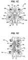
- FIG. 5Ais a posterior view of another embodiment of a spinal stabilization device having first and second cross-connectors with first and second flexible members curved toward from one another and coupled to the cross-connectors at a distance apart from one another;
- FIG. 5Bis a posterior view of the spinal stabilization device shown in FIG. 5A with the cross-connectors moved apart to expand the flexible members;
- FIG. 6Ais a posterior view of another embodiment of a spinal stabilization device having first and second cross-connectors with first and second flexible members curved toward from one another and coupled to the cross-connectors at a position adjacent to one another;
- FIG. 6Bis a posterior view of the spinal stabilization device shown in FIG. 6A with the cross-connectors moved apart to expand the flexible members;
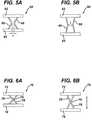
- FIG. 7Ais a posterior view of a spinal stabilization device according to another embodiment having first and second cross-connectors, first and second flexible members connected to the first and second cross-connectors, and a cable connector coupled between the first and second flexible members;
- FIG. 7Bis a posterior view of the spinal stabilization device shown in FIG. 7A showing the cross-connectors moved apart to extend the flexible members;
- FIG. 8is a posterior view of another embodiment of a spinal stabilization device having first and second cross-connectors, first and second flexible members connected to the first and second cross-connectors, and a helical spring connector coupled between the first and second flexible members;
- FIG. 9is a posterior view of another embodiment of a spinal stabilization device having first and second cross-connectors, first and second flexible members connected to the first and second cross-connectors, and a band spring connector coupled between the first and second flexible members;
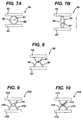
- FIG. 10is a posterior view of another embodiment of a spinal stabilization device having first and second cross-connectors, first and second flexible members connected to the first and second cross-connectors, and a elastomer connector coupled between the first and second flexible members;
- FIG. 11is a posterior view of yet another embodiment of a spinal stabilization device having first and second flexible members coupled to first and second cross-connectors by hinge joints;
- FIG. 12is a posterior view of a spinal stabilization device according to another embodiment having first and second flexible members having hinge joints formed thereon, and being coupled to first and second cross-connectors by hinge joints;
- FIG. 13is a posterior view of another embodiment of a spinal stabilization device having first and second cross-connectors, first and second flexible members connected to the first and second cross-connectors, and a spring coil connector coupled between the first and second flexible members;
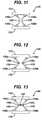
- FIG. 14Ais an illustration of another embodiment of a flexible member formed from a thin metal band having polymeric material disposed on opposed sides thereof;
- FIG. 14Bis a front perspective view of another embodiment of a flexible member having a rectangular configuration
- FIG. 14Cis a side perspective view of the flexible member shown in FIG. 14B ;
- FIG. 15is a posterior view of another embodiment of a stabilization device having first and second cross-connectors coupled to one another by first and second helical springs;
- FIG. 16is a posterior view of another embodiment of a stabilization device having first and second cross-connectors coupled to one another by first and second torsion springs;
- FIG. 17is a posterior view of another spinal stabilization device having first and second cross-connectors with a coil spring disposed around a portion of each cross-connector;
- FIG. 18is a posterior view of yet another embodiment of a spinal stabilization device having first and second cross-connectors coupled by a flexible member having openings formed therethrough;
- FIG. 19is a posterior view of one exemplary embodiment of a flexible mesh coupled between first and second cross-connectors
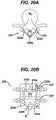
- FIG. 20Ais a superior view of another embodiment of a spinal stabilization device having cross-connectors mated to the spinous processes of the vertebrae coupled thereto;
- FIG. 20Bis a posterior view of the spinal stabilization device and vertebrae shown in FIG. 20A ;
- FIG. 21is a posterior view of a spinal stabilization device coupled to adjacent vertebrae in a spine and having a barrier extending therebetween to separate tissue overlying the device from the tissue underlying the device.
- FIGS. 1A-1Cillustrate one exemplary embodiment of a spinal stabilization device.
- the device 10generally includes a first cross-connector 12 that is adapted to mate to opposed lateral sides of a first vertebra, and a second cross-connector 14 that is adapted to mate to opposed lateral sides of a second adjacent vertebra.
- the device 10also includes a flexible member 16 that mates to the cross-connectors 12 , 14 to allow controlled movement between the adjacent vertebrae, preferably sharing the load applied to the vertebrae and other posterior elements.
- the flexible member 16mates directly to the cross-connectors 12 , 14 , rather than to bone screws or other elements coupled to the cross-connectors.
- Such a configurationcan prevent loosening, such as screw rotation, between the cross-connectors 12 , 14 and the adjacent vertebrae coupled thereto.
- the flexible member 16is particularly advantageous as it can change in length as well as orientation, thereby accommodating changes in the angulation between adjacent vertebrae.
- each cross-connector 12 , 14can each have a variety of configurations.
- each cross-connector 12 , 14is in the form of a rod that has a length that is configured to allow opposed terminal ends 12 a , 12 b , 14 a , 14 b of each cross-connector 12 , 14 to mate to opposed lateral sides of a vertebra.
- Each cross-connector rod 12 , 14can have a linear configuration or can be curved to facilitate positioning of the cross-connectors 12 , 14 relative to adjacent vertebrae.
- the cross-connectors 12 , 14can also be formed from a variety of materials, but preferably the cross-connectors 12 , 14 are substantially rigid. They can, however, be bendable to allow a surgeon to adjust the shape of each cross-connector 12 , 14 to conform to the patient's anatomy.
- One suitable exemplary material for forming the cross-connectors 12 , 14is titanium.
- Each cross-connector 12 , 14can be mated to opposed lateral sides of a vertebra using a variety of mating techniques know in the art.
- first and second superior bone screws 18 s , 20 sare implanted in opposed lateral sides, e.g., in the pedicles, of a superior vertebra Vs
- first and second inferior bone screws 18 i , 20 iare implanted in opposed lateral sides, e.g., in the pedicles, of an adjacent inferior vertebra Vi.
- the bone screws 18 s , 20 s , 18 i , 20 ican have virtually any configuration, and they can be monoaxial or polyaxial bone screws.
- a person skilled in the artwill appreciate that, while bone screws 18 s , 20 s , 18 i , 20 i are shown, a variety of other techniques can be used to mate each cross-connector 12 , 14 to adjacent vertebrae.
- the device 10can also include a flexible member 16 that mates to the first and second cross-connectors 12 , 14 .
- the flexible member 16can have a variety of configurations, and it can be formed from one or more components.
- the flexible member 16is in the form of a composite spring having a substantially circular shape with a central opening 16 o formed therein and first, second, third, and fourth lobes 17 a , 17 b , 17 c , 17 d formed therearound.
- the lobes 17 a, 17 b , 17 c , 17 dfacilitate compression and expansion of the flexible member 16 during movement of the adjacent vertebrae coupled to the device 10 .
- first and third lobes 17 a , 17 ccan extend in a superior-inferior direction such that they can mate to the cross-connectors 12 , 14
- the second and fourth lobes 17 b , 17 dcan extend in a medial-lateral direction such that they are positioned between the cross-connectors 12 , 14 .
- the cross-connectors 12 , 14are moved toward one another during extension of the adjacent vertebrae Vs, Vi coupled thereto, the second and fourth lobes 17 b , 17 d will be compressed.
- the flexible member 16is in the form of a composite spring.
- the flexible member 16can be formed from an elastomeric core 16 a having a thin metal spring 16 b disposed therearound.
- the metal spring 16 bcan be adhered to the core 16 a around the periphery thereof.
- the metal spring 16 bgenerally has a high tensile ultimate strength but a low stiffness, while the elastomeric core 16 a can have a higher stiffness but a low tensile ultimate strength.
- the elastomeric core 16 athus provides stiffness for small movement while the metal spring 16 b provides high ultimate strength to the elastomeric core 16 a.
- the flexible member 16is configured to mate to the cross-connectors 12 , 14 . While a variety of mating techniques, in an exemplary embodiment the flexible member 16 is configured to mate to the cross-connectors 12 , 14 at a fixed location, such that the flexible member 16 does not slide relative to the cross-connectors 12 , 14 .
- the flexible member 16can, however, be adapted to pivot or rotate relative to the cross-connectors 12 , 14 .
- a first clamp member 22is fixedly coupled to the first lobe 17 a on the flexible member 16
- a second clamp member 24is fixedly coupled to the third lobe 17 c on the flexible member 16 .
- Each clamp member 22 , 24has a generally cylindrical shape with an opening 22 a , 24 a formed therethrough.
- the openings 22 a , 24 aeach have an axis that extends parallel to a plane of the flexible member 16 such that the openings 22 a , 24 a extend in a medial-lateral when implanted to allow the cross-connectors 12 , 14 to be slidably disposed therethrough.
- Each clamp member 22 , 24can also include a bore formed through a sidewall thereof and extending into the opening 22 a , 24 a for receiving a fastening element, such as a set screw 22 b , 24 b .
- the set screws 22 b , 24 bcan be effective to lock the cross-connectors 12 , 14 to the clamp members 22 , 24 , thereby providing a rigid connection and preventing sliding movement of the cross-connectors 12 , 14 relative to the flexible member 16 .
- a person skilled in the artwill appreciate that a variety of other techniques can be used to mate the flexible member 16 to the cross-connectors 12 , 14 , including a clamp, hinge, or pivoting connection, etc.
- the flexible member 16 and cross-connector 12 , 14can be pre-mated, or they can be implanted separately. Preferably, the components are pre-mated, however the set screws 22 b , 24 b are not tightened to allow slidable movement of the flexible member 16 .
- Each cross-connector 12 , 14can be mated to the adjacent vertebrae Vs, Vi using, for example, polyaxial bone screws 18 s , 20 s , 18 i , 20 i , as shown in FIG. 1C .
- the flexible member 16can then be slid laterally and positioned as desired.
- FIG. 1Dillustrates three adjacent vertebrae V 1 , V 2 , V 3 , with spinal stabilization device 10 being coupled to the first and second adjacent vertebra V 1 , V 2 .
- a second stabilization 10 ′is coupled to the third vertebra V 3 .
- a first end of a second flexible member 16 ′is coupled to the superior cross-connectors 12 of the first device 10
- a second opposed end of the second flexible member 16 ′is coupled to a third cross-connector 12 ′ mated to the third adjacent vertebrae V 3 .
- Thiscan be repeated to stabilize multiple adjacent vertebrae. Movement of the vertebrae V 1 , V 2 , V 3 will cause the flexible members 16 , 16 ′ to flex, thereby providing resistance to the movement and thus stabilizing the adjacent vertebrae V 1 , V 2 , V 3 and other posterior elements.
- FIGS. 2A-18illustrate various embodiments of flexible members that can be coupled to first and second cross-connectors
- FIG. 19illustrates another embodiment of first and second cross-connectors for mating to adjacent vertebrae.
- the illustrated spinal stabilization devices 30 , 40 , 50 , 60 , 70each include first and second flexible members 36 , 38 , 46 , 48 , 56 , 58 , 66 , 68 , 76 , 78 that extend between and connect to superior and inferior cross-connectors 32 , 34 , 42 , 44 , 52 , 54 , 62 , 64 , 72 , 74 .
- the flexible members 36 , 38 , 46 , 48 , 56 , 58 , 66 , 68 , 76 , 78each have a variety of shapes and configurations. In the embodiment shown in FIGS.
- the flexible members 36 , 38are substantially linear.
- the flexible members 36 , 38will expand when the cross-connectors 32 , 34 move away from one another, i.e., during flexion of the adjacent vertebrae, as shown in FIG. 2B , and they will contract when the cross-connectors 32 , 34 return to the resting position.
- the linear configuration of the flexible members 36 , 38can also be effective to substantially limit or prevent extension of the adjacent vertebrae coupled to the device 30 .
- the flexible memberscan be pre-shaped to have a curved configuration in the resting state. Curved flexible members, as opposed to linear flexible members, can require less strain to flex, thereby providing a larger range motion.
- FIGS. 3A-4Billustrate first and second flexible members 46 , 48 , 56 , 58 that are curved away from one another such that a large opening is formed between the flexible members 46 , 48 , 56 , 58 .
- the curved configuration of the flexible members 46 , 48 , 56 , 58allows the flexible members 46 , 48 , 56 , 58 to straighten, as shown in FIGS. 3B and 4B .
- Such a configurationprovides less resistance during the early stages of flexion than the linear flexible members 36 , 38 shown in FIGS. 2A and 2B .
- the curved flexible members 46 , 48 , 56 , 58become substantially linear, they will begin to stretch thereby providing increased resistance to flexion.
- FIGS. 5A-6Billustrate first and second flexible members 66 , 68 , 76 , 78 that are curved toward one another such that a mid-portion of each flexible member 66 , 68 , 76 , 78 is close to being in contact with one another.
- the curved configuration of the flexible members 66 , 68 , 76 , 78allows the flexible members 66 , 68 , 76 , 78 to straighten, as shown in FIGS. 5B and 6B .
- Such a configurationprovides less resistance during the early stages of flexion than the linear flexible members 36 , 38 shown in FIGS.
- the flexible members 36 , 38 , 46 , 48 , 56 , 58 , 66 , 68 , 76 , 78 in each of the various embodiments shown in FIGS. 2A-6Acan also be positioned at various locations relative to one another, e.g., adjacent to one another or a distance apart from one another relative to the cross-connectors 32 , 34 , 42 , 44 , 52 , 54 , 62 , 64 , 72 , 74 .
- the positioncan be selected to optimize a degree of resistance provided during different movements of the vertebrae.
- FIGS. 3A-3B and 5 A- 5 Billustrate flexible members 46 , 48 , 66 , 68 that are positioned a distance apart from one another.
- FIGS. 4A-4B and 6 A- 6 Billustrate flexible members 56 , 58 , 76 , 78 that are positioned adjacent to one another.
- the terminal ends of the flexible members 56 , 58are substantially in contact with one another or joined.
- the mid-portion of the flexible members 76 , 78are substantially in contact with one another or joined. Such a configuration provides less resistance to lateral bending.
- the flexible memberscan be positioned outside of the bone screws that mate the cross-connectors to the vertebrae, i.e., lateral to the bone screws. Such a configuration may allow the flexible members to be positioned closer to the anterior side of the adjacent vertebrae.
- the flexible memberscan be coupled to one another, either directly or by a connector, to further increase or decrease the resistance provided by the flexible members during movement of the adjacent vertebrae coupled thereto.
- FIGS. 6A and 6Billustrate flexible members 76 , 78 connected directly to one another at a mid-portion thereof. The connection will constrain the flexible members 76 , 78 and limit the ability of the flexible members 76 , 78 to straighten during flexion of the adjacent vertebrae coupled to the device 70 , thereby limiting flexion. The connection between the flexible members 76 , 78 will also limit or prevent extension of adjacent vertebrae coupled thereto, as was also previously discussed.
- FIGS. 7A-13illustrate various exemplary embodiments of connectors for mating the flexible members to one another.
- the device 70includes a connector that is in the form of a cable or cord 87 that extends between a mid-portion of each flexible member 86 , 88 .
- the cable 87allows straightening of the flexible members 86 , 88 when the cross-connectors 82 , 84 move away from one another, e.g., during flexion of the adjacent vertebrae coupled thereto.
- the cable 87can function as a physical stop preventing the flexible members 86 , 88 from being further compressed and thereby preventing further movement of the cross-connectors 82 , 84 toward one another.
- FIGS. 8 , 9 , and 10each illustrate a spinal stabilization device 90 , 100 , 110 having a helical or coil spring 97 ( FIG. 8 ), a band spring 107 ( FIG. 9 ), or an elastomeric material 117 ( FIG.
- the amount of movement of adjacent vertebrae coupled to a spinal stabilization devicecan also be controlled by varying the connection between the flexible member(s) and the cross-connectors.
- the flexible member(s)can be pivotally or hingedly coupled to the cross-connectors to reduce the amount of stress or strain applied to the ends of the flexible member(s), and to allow a greater range of motion between the adjacent vertebrae coupled thereto.
- 11-13illustrate various exemplary embodiments of stabilization devices 120 , 130 , 140 having hinge joints 126 a, 126 b , 128 a , 128 b , 136 a , 136 b , 138 a , 138 b , 146 a , 146 b , 148 a , 148 b formed between the flexible members 126 , 128 , 136 , 138 , 146 , 148 and the cross-connectors 122 , 124 , 132 , 134 , 142 , 144 .
- the hinge joints 126 a , 126 b , 128 a , 128 b , 136 a , 136 b , 138 a , 138 b , 146 a , 146 b , 148 a , 148 ballow pivotal motion in the sagittal plane when the device 120 , 130 , 140 is implanted. As shown in FIGS.
- the flexible members 136 , 138 , 146 , 148can also optionally include one or more hinge joints 136 c , 138 c , 146 c , 148 c formed along a length thereof, e.g., at a mid-portion of each flexible member 136 , 138 , 146 , 148 .
- Such a configurationprovides additional flexibility and movement when the device 130 , 140 is implanted.
- the hinge joints 136 c , 138 c , 146 c , 148 c formed along a length of each flexible member 136 , 138 , 146 , 148can also be coupled to one another by a connector. For example, FIG.
- FIGS. 11-13illustrated a connector 147 in the form of a coil spring extending between and coupled to the hinges joints 146 c , 148 c formed at the mid-portion of the flexible members 146 , 148 .
- a person skilled in the artwill appreciate that a variety of techniques can be used to provide a hinge or pivotal joint.
- the hinge joints in the various embodiments shown in FIGS. 11-13can also optionally be formed from an elastomeric material, allowing additional stretching to occur between the cross-connectors and the flexible members.
- each flexible membercan also vary to provide a desired amount of resistance during movement of the adjacent vertebrae coupled to the device.
- the material(s) used to form the flexible memberscan be selected to obtain a desired result during use of the device.
- the flexible membersare formed from a polymeric material, such as polyurethane.
- the flexible memberscould also optionally include a support structure to provide rigidity to all or a portion of the flexible members.
- FIG. 14Aillustrates another embodiment of a flexible member 150 formed from a metal band 150 a having an elastomeric material 150 b , 150 c mated to opposed sides thereof to form a composite beam.
- FIGS. 14B and 14Cillustrate a flexible member 160 having a rectangular cross-section with a first width w 1 that is greater than a second width w 2 .
- the rectangular cross-sectionwill provide a higher amount of resistance when bent in a first direction, as shown in phantom in FIG. 14B , than when bent in a second direction that is substantially transverse to the first direction.
- the second directionis shown in phantom in FIG. 14C .
- Such a configurationcan, for example, allow flexion and extension of the spine while resisting anterior-posterior shear.
- the configuration of the flexible memberscan also vary along a length of the flexible member.
- a flexible membercan be more flexible at a mid-portion than at the end portions, thereby reducing the strain or stress at the mid-portion of the flexible member.
- FIGS. 15-19illustrate other embodiments of flexible members for use with a spinal stabilization device.
- the device 170includes two flexible members in the form of helical or coil springs 176 , 178 that extend between superior and inferior cross-connectors 172 , 174 .
- FIG. 16illustrates another embodiment of a device 180 having flexible members in the form of springs, however in this embodiment the flexible members are torsion springs 186 , 188 that extend between superior and inferior cross-connectors 182 , 184 .
- FIG. 15-19illustrate other embodiments of flexible members for use with a spinal stabilization device.
- the device 170includes two flexible members in the form of helical or coil springs 176 , 178 that extend between superior and inferior cross-connectors 172 , 174 .
- FIG. 16illustrates another embodiment of a device 180 having flexible members in the form of springs, however in this embodiment the flexible members are torsion springs 186 , 188 that extend between superior and inferior cross-connectors 18
- the device 190can include a helical or coil spring 196 that is wrapped around an intermediate portion of each cross-connector 192 , 194 to form a flexible member.
- FIG. 18illustrates yet another embodiment of a spinal stabilization device 200 having an flexible body 206 that is coupled to superior and inferior cross-connectors 202 , 204 , and that includes two openings 206 a , 206 b formed therein to increase the flexibility of the body 206 . While two openings are shown, the flexible body 206 can include any number of openings.
- FIG. 19illustrates yet another embodiment of a spinal stabilization device 210 having a flexible member 216 extending between superior and inferior cross-connectors 212 , 214 . In this embodiment, the flexible member 216 is in the form of a mesh material.
- the configuration of the cross-connectorscan vary to accommodate the anatomy of the spine.
- the stabilization device 220can include superior and inferior cross-connectors 222 , 224 that are adapted to mate to opposed lateral sides of superior and inferior vertebrae Vs, Vi, and that are adapted to mate to the superior and inferior spinous processes Ss, Si of the adjacent vertebrae Vs, Vi.
- each cross-connectors 222 , 224can be formed from first and second members 222 a , 222 b , 224 a , 224 b that are adapted to extend between a lateral side of the vertebra Vs, Vi and the spinous process Ss, Si.
- a thru-borecan be formed in one end of each of the first and second members 222 a , 222 b , 224 a , 224 b for receiving a bone screw 230 a, 230 b for mating the ends of the members 222 a , 222 b , 224 a , 224 b to the spinous processes Ss, Si and optionally to one another.
- Such a configurationis particularly advantageous as it does not require removal of the spinous processes Ss, Si, and it prevents large moment on the pedicle screws used to couple the cross-connectors 222 , 224 to the opposed lateral sides of the vertebrae Vs, Vi.
- the spinal stabilization devicecan be covered and/or coated with a protective material or barrier that is adapted to protect the device from cell attachment and/or tissue ingrowth, which could potentially interfere with the function of the device.
- FIG. 21illustrates one exemplary embodiment of a spinal stabilization device 200 having superior and inferior cross-connectors 302 , 304 coupled to adjacent vertebrae Vs, Vi, and first and second flexible members 306 , 308 extending between the superior and inferior cross-connectors 302 , 304 .
- a protective barrier 310 in the form of an elongate sheet of materialextends between the superior and inferior cross-connectors 302 , 304 to separate tissue overlying the device 200 from the tissue underlying the device, e.g., the dura mater surrounding the spinal cord.
- the barrier 310can also optionally be positioned over the flexible members 306 , 308 , and/or it can couple to the flexible members 306 , 308 .
- the barrier 310can be mated to the cross-connectors 302 , 304 and/or flexible members 306 , 308 using a variety of mating techniques known in the art.
- the barrier 310can also be formed from a variety of materials, but in one exemplary embodiment the barrier 310 is formed from a polytetrafluoroethylene or Silastic® (polydimethyl siloxane elastomer).
- the flexible members 306 , 308 and/or cross-connectors 302 , 304can be covered with a protective material, such as a non-fouling material that inhibits cell attachment and ingrowth.
Landscapes
- Health & Medical Sciences (AREA)
- Orthopedic Medicine & Surgery (AREA)
- Life Sciences & Earth Sciences (AREA)
- Neurology (AREA)
- Surgery (AREA)
- Heart & Thoracic Surgery (AREA)
- Engineering & Computer Science (AREA)
- Biomedical Technology (AREA)
- Nuclear Medicine, Radiotherapy & Molecular Imaging (AREA)
- Medical Informatics (AREA)
- Molecular Biology (AREA)
- Animal Behavior & Ethology (AREA)
- General Health & Medical Sciences (AREA)
- Public Health (AREA)
- Veterinary Medicine (AREA)
- Prostheses (AREA)
- Surgical Instruments (AREA)
Abstract
Description
Claims (14)
Priority Applications (2)
| Application Number | Priority Date | Filing Date | Title |
|---|---|---|---|
| US11/162,880US7879074B2 (en) | 2005-09-27 | 2005-09-27 | Posterior dynamic stabilization systems and methods |
| PCT/US2006/031264WO2007037801A2 (en) | 2005-09-27 | 2006-08-09 | Posterior dynamic stabilization systems and methods |
Applications Claiming Priority (1)
| Application Number | Priority Date | Filing Date | Title |
|---|---|---|---|
| US11/162,880US7879074B2 (en) | 2005-09-27 | 2005-09-27 | Posterior dynamic stabilization systems and methods |
Publications (2)
| Publication Number | Publication Date |
|---|---|
| US20070073289A1 US20070073289A1 (en) | 2007-03-29 |
| US7879074B2true US7879074B2 (en) | 2011-02-01 |
Family
ID=37895131
Family Applications (1)
| Application Number | Title | Priority Date | Filing Date |
|---|---|---|---|
| US11/162,880Active2025-12-05US7879074B2 (en) | 2005-09-27 | 2005-09-27 | Posterior dynamic stabilization systems and methods |
Country Status (2)
| Country | Link |
|---|---|
| US (1) | US7879074B2 (en) |
| WO (1) | WO2007037801A2 (en) |
Cited By (46)
| Publication number | Priority date | Publication date | Assignee | Title |
|---|---|---|---|---|
| US20070123866A1 (en)* | 2005-10-31 | 2007-05-31 | Stryker Spine | System and method for dynamic vertebral stabilization |
| US20070260125A1 (en)* | 2006-05-02 | 2007-11-08 | Strauss Kevin R | Minimally open retraction device |
| US20080281358A1 (en)* | 2006-12-11 | 2008-11-13 | Abdou M S | Dynamic spinal stabilization systems and methods of use |
| US20090036928A1 (en)* | 2004-08-27 | 2009-02-05 | Depuy Spine, Inc. | Dual rod cross connectors and inserter tools |
| US20100030279A1 (en)* | 2008-02-26 | 2010-02-04 | Spartek Medical, Inc. | Load-sharing bone anchor having a deflectable post and axial spring and method for dynamic stabilization of the spine |
| US20100030274A1 (en)* | 2007-06-05 | 2010-02-04 | Spartek Medical, Inc. | Dynamic spinal rod and method for dynamic stabilization of the spine |
| US20100030267A1 (en)* | 2007-06-05 | 2010-02-04 | Spartek Medical, Inc. | Surgical tool and method for implantation of a dynamic bone anchor |
| US20100030224A1 (en)* | 2008-02-26 | 2010-02-04 | Spartek Medical, Inc. | Surgical tool and method for connecting a dynamic bone anchor and dynamic vertical rod |
| US20100030271A1 (en)* | 2008-02-26 | 2010-02-04 | Spartek Medical, Inc. | Modular in-line deflection rod and bone anchor system and method for dynamic stabilization of the spine |
| US20100030270A1 (en)* | 2007-06-05 | 2010-02-04 | Spartek Medical, Inc. | Dynamic spinal rod assembly and method for dynamic stabilization of the spine |
| US20100036435A1 (en)* | 2008-02-26 | 2010-02-11 | Spartek Medical, Inc. | Load-sharing bone anchor having a deflectable post and method for dynamic stabilization of the spine |
| US20100036436A1 (en)* | 2008-02-26 | 2010-02-11 | Spartek Medical, Inc. | Load-sharing bone anchor having a durable compliant member and method for dynamic stabilization of the spine |
| US20100036437A1 (en)* | 2008-02-26 | 2010-02-11 | Spartek Medical, Inc. | Load-sharing bone anchor having a deflectable post with a compliant ring and method for stabilization of the spine |
| US20100036426A1 (en)* | 2008-02-26 | 2010-02-11 | Spartek Medical, Inc. | Versatile offset polyaxial connector and method for dynamic stabilization of the spine |
| US20100057139A1 (en)* | 2007-06-05 | 2010-03-04 | Spartek Medical, Inc. | Bone anchor for receiving a rod for stabilization and motion preservation spinal implantation system and method |
| US20100168795A1 (en)* | 2008-02-26 | 2010-07-01 | Spartek Medical, Inc. | Load-sharing bone anchor having a natural center of rotation and method for dynamic stabilization of the spine |
| US20110118783A1 (en)* | 2009-11-16 | 2011-05-19 | Spartek Medical, Inc. | Load-sharing bone anchor having a flexible post and method for dynamic stabilization of the spine |
| US8021396B2 (en) | 2007-06-05 | 2011-09-20 | Spartek Medical, Inc. | Configurable dynamic spinal rod and method for dynamic stabilization of the spine |
| US8057517B2 (en) | 2008-02-26 | 2011-11-15 | Spartek Medical, Inc. | Load-sharing component having a deflectable post and centering spring and method for dynamic stabilization of the spine |
| US8097024B2 (en) | 2008-02-26 | 2012-01-17 | Spartek Medical, Inc. | Load-sharing bone anchor having a deflectable post and method for stabilization of the spine |
| US8114134B2 (en) | 2007-06-05 | 2012-02-14 | Spartek Medical, Inc. | Spinal prosthesis having a three bar linkage for motion preservation and dynamic stabilization of the spine |
| US8226687B2 (en) | 2005-02-22 | 2012-07-24 | Stryker Spine | Apparatus and method for dynamic vertebral stabilization |
| US8257397B2 (en) | 2009-12-02 | 2012-09-04 | Spartek Medical, Inc. | Low profile spinal prosthesis incorporating a bone anchor having a deflectable post and a compound spinal rod |
| US8337536B2 (en) | 2008-02-26 | 2012-12-25 | Spartek Medical, Inc. | Load-sharing bone anchor having a deflectable post with a compliant ring and method for stabilization of the spine |
| US8361117B2 (en) | 2006-11-08 | 2013-01-29 | Depuy Spine, Inc. | Spinal cross connectors |
| US8430916B1 (en) | 2012-02-07 | 2013-04-30 | Spartek Medical, Inc. | Spinal rod connectors, methods of use, and spinal prosthesis incorporating spinal rod connectors |
| US8518085B2 (en) | 2010-06-10 | 2013-08-27 | Spartek Medical, Inc. | Adaptive spinal rod and methods for stabilization of the spine |
| US8556937B2 (en) | 2004-03-31 | 2013-10-15 | DePuy Synthes Products, LLC | Rod attachment for head to head cross connector |
| US8864828B2 (en) | 2004-10-20 | 2014-10-21 | Vertiflex, Inc. | Interspinous spacer |
| US8900271B2 (en) | 2004-10-20 | 2014-12-02 | The Board Of Trustees Of The Leland Stanford Junior University | Systems and methods for posterior dynamic stabilization of the spine |
| US8920475B1 (en) | 2011-01-07 | 2014-12-30 | Lanx, Inc. | Vertebral fixation system including torque mitigation |
| US9039742B2 (en) | 2004-10-20 | 2015-05-26 | The Board Of Trustees Of The Leland Stanford Junior University | Systems and methods for posterior dynamic stabilization of the spine |
| US9119680B2 (en) | 2004-10-20 | 2015-09-01 | Vertiflex, Inc. | Interspinous spacer |
| US9155570B2 (en) | 2004-10-20 | 2015-10-13 | Vertiflex, Inc. | Interspinous spacer |
| US10149674B2 (en) | 2015-08-12 | 2018-12-11 | K2M, Inc. | Orthopedic surgical system including surgical access systems, distraction systems, and methods of using same |
| US10499894B2 (en) | 2015-08-12 | 2019-12-10 | K2M, Inc. | Orthopedic surgical system including surgical access systems, distraction systems, and methods of using same |
| US10543107B2 (en) | 2009-12-07 | 2020-01-28 | Samy Abdou | Devices and methods for minimally invasive spinal stabilization and instrumentation |
| US10548740B1 (en) | 2016-10-25 | 2020-02-04 | Samy Abdou | Devices and methods for vertebral bone realignment |
| US10575961B1 (en) | 2011-09-23 | 2020-03-03 | Samy Abdou | Spinal fixation devices and methods of use |
| US10695105B2 (en) | 2012-08-28 | 2020-06-30 | Samy Abdou | Spinal fixation devices and methods of use |
| US10857003B1 (en) | 2015-10-14 | 2020-12-08 | Samy Abdou | Devices and methods for vertebral stabilization |
| US10918498B2 (en) | 2004-11-24 | 2021-02-16 | Samy Abdou | Devices and methods for inter-vertebral orthopedic device placement |
| US10973648B1 (en) | 2016-10-25 | 2021-04-13 | Samy Abdou | Devices and methods for vertebral bone realignment |
| US11006982B2 (en) | 2012-02-22 | 2021-05-18 | Samy Abdou | Spinous process fixation devices and methods of use |
| US11173040B2 (en) | 2012-10-22 | 2021-11-16 | Cogent Spine, LLC | Devices and methods for spinal stabilization and instrumentation |
| US11179248B2 (en) | 2018-10-02 | 2021-11-23 | Samy Abdou | Devices and methods for spinal implantation |
Families Citing this family (174)
| Publication number | Priority date | Publication date | Assignee | Title |
|---|---|---|---|---|
| US7201751B2 (en)* | 1997-01-02 | 2007-04-10 | St. Francis Medical Technologies, Inc. | Supplemental spine fixation device |
| US6068630A (en) | 1997-01-02 | 2000-05-30 | St. Francis Medical Technologies, Inc. | Spine distraction implant |
| US7959652B2 (en)* | 2005-04-18 | 2011-06-14 | Kyphon Sarl | Interspinous process implant having deployable wings and method of implantation |
| US20080086212A1 (en) | 1997-01-02 | 2008-04-10 | St. Francis Medical Technologies, Inc. | Spine distraction implant |
| US20050245937A1 (en)* | 2004-04-28 | 2005-11-03 | St. Francis Medical Technologies, Inc. | System and method for insertion of an interspinous process implant that is rotatable in order to retain the implant relative to the spinous processes |
| US20080039859A1 (en)* | 1997-01-02 | 2008-02-14 | Zucherman James F | Spine distraction implant and method |
| FR2812185B1 (en)* | 2000-07-25 | 2003-02-28 | Spine Next Sa | SEMI-RIGID CONNECTION PIECE FOR RACHIS STABILIZATION |
| US7833250B2 (en) | 2004-11-10 | 2010-11-16 | Jackson Roger P | Polyaxial bone screw with helically wound capture connection |
| US10729469B2 (en) | 2006-01-09 | 2020-08-04 | Roger P. Jackson | Flexible spinal stabilization assembly with spacer having off-axis core member |
| US10258382B2 (en) | 2007-01-18 | 2019-04-16 | Roger P. Jackson | Rod-cord dynamic connection assemblies with slidable bone anchor attachment members along the cord |
| US8292926B2 (en) | 2005-09-30 | 2012-10-23 | Jackson Roger P | Dynamic stabilization connecting member with elastic core and outer sleeve |
| US8353932B2 (en) | 2005-09-30 | 2013-01-15 | Jackson Roger P | Polyaxial bone anchor assembly with one-piece closure, pressure insert and plastic elongate member |
| US7862587B2 (en) | 2004-02-27 | 2011-01-04 | Jackson Roger P | Dynamic stabilization assemblies, tool set and method |
| WO2006052796A2 (en) | 2004-11-10 | 2006-05-18 | Jackson Roger P | Helical guide and advancement flange with break-off extensions |
| US8876868B2 (en) | 2002-09-06 | 2014-11-04 | Roger P. Jackson | Helical guide and advancement flange with radially loaded lip |
| US20060264939A1 (en)* | 2003-05-22 | 2006-11-23 | St. Francis Medical Technologies, Inc. | Interspinous process implant with slide-in distraction piece and method of implantation |
| US7931674B2 (en) | 2005-03-21 | 2011-04-26 | Kyphon Sarl | Interspinous process implant having deployable wing and method of implantation |
| US20080021468A1 (en)* | 2002-10-29 | 2008-01-24 | Zucherman James F | Interspinous process implants and methods of use |
| US8147548B2 (en)* | 2005-03-21 | 2012-04-03 | Kyphon Sarl | Interspinous process implant having a thread-shaped wing and method of implantation |
| US7549999B2 (en) | 2003-05-22 | 2009-06-23 | Kyphon Sarl | Interspinous process distraction implant and method of implantation |
| US8048117B2 (en)* | 2003-05-22 | 2011-11-01 | Kyphon Sarl | Interspinous process implant and method of implantation |
| US7621918B2 (en) | 2004-11-23 | 2009-11-24 | Jackson Roger P | Spinal fixation tool set and method |
| US7377923B2 (en) | 2003-05-22 | 2008-05-27 | Alphatec Spine, Inc. | Variable angle spinal screw assembly |
| US8926670B2 (en) | 2003-06-18 | 2015-01-06 | Roger P. Jackson | Polyaxial bone screw assembly |
| US7967850B2 (en) | 2003-06-18 | 2011-06-28 | Jackson Roger P | Polyaxial bone anchor with helical capture connection, insert and dual locking assembly |
| US8366753B2 (en) | 2003-06-18 | 2013-02-05 | Jackson Roger P | Polyaxial bone screw assembly with fixed retaining structure |
| US8092500B2 (en) | 2007-05-01 | 2012-01-10 | Jackson Roger P | Dynamic stabilization connecting member with floating core, compression spacer and over-mold |
| US7776067B2 (en) | 2005-05-27 | 2010-08-17 | Jackson Roger P | Polyaxial bone screw with shank articulation pressure insert and method |
| US7766915B2 (en) | 2004-02-27 | 2010-08-03 | Jackson Roger P | Dynamic fixation assemblies with inner core and outer coil-like member |
| US7527638B2 (en) | 2003-12-16 | 2009-05-05 | Depuy Spine, Inc. | Methods and devices for minimally invasive spinal fixation element placement |
| US11419642B2 (en) | 2003-12-16 | 2022-08-23 | Medos International Sarl | Percutaneous access devices and bone anchor assemblies |
| US7179261B2 (en) | 2003-12-16 | 2007-02-20 | Depuy Spine, Inc. | Percutaneous access devices and bone anchor assemblies |
| JP2007525274A (en) | 2004-02-27 | 2007-09-06 | ロジャー・ピー・ジャクソン | Orthopedic implant rod reduction instrument set and method |
| US11241261B2 (en) | 2005-09-30 | 2022-02-08 | Roger P Jackson | Apparatus and method for soft spinal stabilization using a tensionable cord and releasable end structure |
| US7160300B2 (en) | 2004-02-27 | 2007-01-09 | Jackson Roger P | Orthopedic implant rod reduction tool set and method |
| US8152810B2 (en) | 2004-11-23 | 2012-04-10 | Jackson Roger P | Spinal fixation tool set and method |
| FR2870718B1 (en)* | 2004-05-25 | 2006-09-22 | Spine Next Sa | TREATMENT ASSEMBLY FOR THE DEGENERATION OF AN INTERVERTEBRAL DISC |
| US8012209B2 (en)* | 2004-09-23 | 2011-09-06 | Kyphon Sarl | Interspinous process implant including a binder, binder aligner and method of implantation |
| US7651502B2 (en) | 2004-09-24 | 2010-01-26 | Jackson Roger P | Spinal fixation tool set and method for rod reduction and fastener insertion |
| US8128662B2 (en) | 2004-10-20 | 2012-03-06 | Vertiflex, Inc. | Minimally invasive tooling for delivery of interspinous spacer |
| US9023084B2 (en) | 2004-10-20 | 2015-05-05 | The Board Of Trustees Of The Leland Stanford Junior University | Systems and methods for stabilizing the motion or adjusting the position of the spine |
| US8409282B2 (en) | 2004-10-20 | 2013-04-02 | Vertiflex, Inc. | Systems and methods for posterior dynamic stabilization of the spine |
| US8277488B2 (en)* | 2004-10-20 | 2012-10-02 | Vertiflex, Inc. | Interspinous spacer |
| US8945183B2 (en)* | 2004-10-20 | 2015-02-03 | Vertiflex, Inc. | Interspinous process spacer instrument system with deployment indicator |
| US7935134B2 (en)* | 2004-10-20 | 2011-05-03 | Exactech, Inc. | Systems and methods for stabilization of bone structures |
| US8123807B2 (en)* | 2004-10-20 | 2012-02-28 | Vertiflex, Inc. | Systems and methods for posterior dynamic stabilization of the spine |
| US8012207B2 (en) | 2004-10-20 | 2011-09-06 | Vertiflex, Inc. | Systems and methods for posterior dynamic stabilization of the spine |
| US8162985B2 (en)* | 2004-10-20 | 2012-04-24 | The Board Of Trustees Of The Leland Stanford Junior University | Systems and methods for posterior dynamic stabilization of the spine |
| US8025680B2 (en)* | 2004-10-20 | 2011-09-27 | Exactech, Inc. | Systems and methods for posterior dynamic stabilization of the spine |
| US9161783B2 (en) | 2004-10-20 | 2015-10-20 | Vertiflex, Inc. | Interspinous spacer |
| US8425559B2 (en) | 2004-10-20 | 2013-04-23 | Vertiflex, Inc. | Systems and methods for posterior dynamic stabilization of the spine |
| US20070239159A1 (en)* | 2005-07-22 | 2007-10-11 | Vertiflex, Inc. | Systems and methods for stabilization of bone structures |
| US8317864B2 (en) | 2004-10-20 | 2012-11-27 | The Board Of Trustees Of The Leland Stanford Junior University | Systems and methods for posterior dynamic stabilization of the spine |
| US7763074B2 (en) | 2004-10-20 | 2010-07-27 | The Board Of Trustees Of The Leland Stanford Junior University | Systems and methods for posterior dynamic stabilization of the spine |
| US8267969B2 (en)* | 2004-10-20 | 2012-09-18 | Exactech, Inc. | Screw systems and methods for use in stabilization of bone structures |
| US8613747B2 (en)* | 2004-10-20 | 2013-12-24 | Vertiflex, Inc. | Spacer insertion instrument |
| US8123782B2 (en) | 2004-10-20 | 2012-02-28 | Vertiflex, Inc. | Interspinous spacer |
| US8226690B2 (en)* | 2005-07-22 | 2012-07-24 | The Board Of Trustees Of The Leland Stanford Junior University | Systems and methods for stabilization of bone structures |
| US8926672B2 (en) | 2004-11-10 | 2015-01-06 | Roger P. Jackson | Splay control closure for open bone anchor |
| US9168069B2 (en) | 2009-06-15 | 2015-10-27 | Roger P. Jackson | Polyaxial bone anchor with pop-on shank and winged insert with lower skirt for engaging a friction fit retainer |
| WO2006057837A1 (en) | 2004-11-23 | 2006-06-01 | Jackson Roger P | Spinal fixation tool attachment structure |
| US8444681B2 (en) | 2009-06-15 | 2013-05-21 | Roger P. Jackson | Polyaxial bone anchor with pop-on shank, friction fit retainer and winged insert |
| US9980753B2 (en) | 2009-06-15 | 2018-05-29 | Roger P Jackson | pivotal anchor with snap-in-place insert having rotation blocking extensions |
| US9216041B2 (en) | 2009-06-15 | 2015-12-22 | Roger P. Jackson | Spinal connecting members with tensioned cords and rigid sleeves for engaging compression inserts |
| EP2219538B1 (en) | 2004-12-06 | 2022-07-06 | Vertiflex, Inc. | Spacer insertion instrument |
| US8157841B2 (en)* | 2005-02-17 | 2012-04-17 | Kyphon Sarl | Percutaneous spinal implants and methods |
| US8029567B2 (en)* | 2005-02-17 | 2011-10-04 | Kyphon Sarl | Percutaneous spinal implants and methods |
| US8007521B2 (en)* | 2005-02-17 | 2011-08-30 | Kyphon Sarl | Percutaneous spinal implants and methods |
| US8034080B2 (en) | 2005-02-17 | 2011-10-11 | Kyphon Sarl | Percutaneous spinal implants and methods |
| US8038698B2 (en) | 2005-02-17 | 2011-10-18 | Kphon Sarl | Percutaneous spinal implants and methods |
| US8100943B2 (en)* | 2005-02-17 | 2012-01-24 | Kyphon Sarl | Percutaneous spinal implants and methods |
| US20070276493A1 (en)* | 2005-02-17 | 2007-11-29 | Malandain Hugues F | Percutaneous spinal implants and methods |
| US8096994B2 (en) | 2005-02-17 | 2012-01-17 | Kyphon Sarl | Percutaneous spinal implants and methods |
| US7998174B2 (en)* | 2005-02-17 | 2011-08-16 | Kyphon Sarl | Percutaneous spinal implants and methods |
| US8057513B2 (en)* | 2005-02-17 | 2011-11-15 | Kyphon Sarl | Percutaneous spinal implants and methods |
| US8097018B2 (en)* | 2005-02-17 | 2012-01-17 | Kyphon Sarl | Percutaneous spinal implants and methods |
| US7988709B2 (en)* | 2005-02-17 | 2011-08-02 | Kyphon Sarl | Percutaneous spinal implants and methods |
| US10076361B2 (en) | 2005-02-22 | 2018-09-18 | Roger P. Jackson | Polyaxial bone screw with spherical capture, compression and alignment and retention structures |
| US7901437B2 (en) | 2007-01-26 | 2011-03-08 | Jackson Roger P | Dynamic stabilization member with molded connection |
| US8034079B2 (en) | 2005-04-12 | 2011-10-11 | Warsaw Orthopedic, Inc. | Implants and methods for posterior dynamic stabilization of a spinal motion segment |
| US7727233B2 (en)* | 2005-04-29 | 2010-06-01 | Warsaw Orthopedic, Inc. | Spinous process stabilization devices and methods |
| US8523865B2 (en) | 2005-07-22 | 2013-09-03 | Exactech, Inc. | Tissue splitter |
| US8105368B2 (en) | 2005-09-30 | 2012-01-31 | Jackson Roger P | Dynamic stabilization connecting member with slitted core and outer sleeve |
| US8083795B2 (en)* | 2006-01-18 | 2011-12-27 | Warsaw Orthopedic, Inc. | Intervertebral prosthetic device for spinal stabilization and method of manufacturing same |
| US7578849B2 (en)* | 2006-01-27 | 2009-08-25 | Warsaw Orthopedic, Inc. | Intervertebral implants and methods of use |
| US7815663B2 (en)* | 2006-01-27 | 2010-10-19 | Warsaw Orthopedic, Inc. | Vertebral rods and methods of use |
| US7682376B2 (en)* | 2006-01-27 | 2010-03-23 | Warsaw Orthopedic, Inc. | Interspinous devices and methods of use |
| US8262698B2 (en)* | 2006-03-16 | 2012-09-11 | Warsaw Orthopedic, Inc. | Expandable device for insertion between anatomical structures and a procedure utilizing same |
| US8118844B2 (en)* | 2006-04-24 | 2012-02-21 | Warsaw Orthopedic, Inc. | Expandable device for insertion between anatomical structures and a procedure utilizing same |
| US8048118B2 (en)* | 2006-04-28 | 2011-11-01 | Warsaw Orthopedic, Inc. | Adjustable interspinous process brace |
| US8105357B2 (en)* | 2006-04-28 | 2012-01-31 | Warsaw Orthopedic, Inc. | Interspinous process brace |
| US8062337B2 (en)* | 2006-05-04 | 2011-11-22 | Warsaw Orthopedic, Inc. | Expandable device for insertion between anatomical structures and a procedure utilizing same |
| US8012179B2 (en)* | 2006-05-08 | 2011-09-06 | Warsaw Orthopedic, Inc. | Dynamic spinal stabilization members and methods |
| US20080058808A1 (en) | 2006-06-14 | 2008-03-06 | Spartek Medical, Inc. | Implant system and method to treat degenerative disorders of the spine |
| US7666211B2 (en)* | 2006-12-28 | 2010-02-23 | Mi4Spine, Llc | Vertebral disc annular fibrosis tensioning and lengthening device |
| US8048119B2 (en)* | 2006-07-20 | 2011-11-01 | Warsaw Orthopedic, Inc. | Apparatus for insertion between anatomical structures and a procedure utilizing same |
| US20080086115A1 (en) | 2006-09-07 | 2008-04-10 | Warsaw Orthopedic, Inc. | Intercostal spacer device and method for use in correcting a spinal deformity |
| US8845726B2 (en) | 2006-10-18 | 2014-09-30 | Vertiflex, Inc. | Dilator |
| US8097019B2 (en) | 2006-10-24 | 2012-01-17 | Kyphon Sarl | Systems and methods for in situ assembly of an interspinous process distraction implant |
| US8096996B2 (en) | 2007-03-20 | 2012-01-17 | Exactech, Inc. | Rod reducer |
| FR2908035B1 (en)* | 2006-11-08 | 2009-05-01 | Jean Taylor | INTEREPINE IMPLANT |
| US20080114455A1 (en)* | 2006-11-15 | 2008-05-15 | Warsaw Orthopedic, Inc. | Rotating Interspinous Process Devices and Methods of Use |
| CA2670988C (en) | 2006-12-08 | 2014-03-25 | Roger P. Jackson | Tool system for dynamic spinal implants |
| US7955392B2 (en)* | 2006-12-14 | 2011-06-07 | Warsaw Orthopedic, Inc. | Interspinous process devices and methods |
| US8366745B2 (en) | 2007-05-01 | 2013-02-05 | Jackson Roger P | Dynamic stabilization assembly having pre-compressed spacers with differential displacements |
| US8475498B2 (en) | 2007-01-18 | 2013-07-02 | Roger P. Jackson | Dynamic stabilization connecting member with cord connection |
| US8012177B2 (en) | 2007-02-12 | 2011-09-06 | Jackson Roger P | Dynamic stabilization assembly with frusto-conical connection |
| AU2008241447B2 (en) | 2007-04-16 | 2014-03-27 | Vertiflex, Inc. | Interspinous spacer |
| US10383660B2 (en) | 2007-05-01 | 2019-08-20 | Roger P. Jackson | Soft stabilization assemblies with pretensioned cords |
| US8979904B2 (en) | 2007-05-01 | 2015-03-17 | Roger P Jackson | Connecting member with tensioned cord, low profile rigid sleeve and spacer with torsion control |
| US20080294200A1 (en)* | 2007-05-25 | 2008-11-27 | Andrew Kohm | Spinous process implants and methods of using the same |
| CA2690038C (en) | 2007-05-31 | 2012-11-27 | Roger P. Jackson | Dynamic stabilization connecting member with pre-tensioned solid core |
| US8109970B2 (en) | 2007-06-05 | 2012-02-07 | Spartek Medical, Inc. | Deflection rod system with a deflection contouring shield for a spine implant and method |
| US8052722B2 (en) | 2007-06-05 | 2011-11-08 | Spartek Medical, Inc. | Dual deflection rod system for a dynamic stabilization and motion preservation spinal implantation system and method |
| US20080312694A1 (en)* | 2007-06-15 | 2008-12-18 | Peterman Marc M | Dynamic stabilization rod for spinal implants and methods for manufacturing the same |
| US20090093843A1 (en)* | 2007-10-05 | 2009-04-09 | Lemoine Jeremy J | Dynamic spine stabilization system |
| US8911477B2 (en) | 2007-10-23 | 2014-12-16 | Roger P. Jackson | Dynamic stabilization member with end plate support and cable core extension |
| US20090112266A1 (en)* | 2007-10-25 | 2009-04-30 | Industrial Technology Research Institute | Spinal dynamic stabilization device |
| US20090131984A1 (en)* | 2007-11-19 | 2009-05-21 | Linares Miguel A | Spine support implant including inter vertebral insertable fluid ballastable insert and inter-vertebral web retaining harnesses |
| US8021400B2 (en)* | 2007-12-13 | 2011-09-20 | Trinity Orthopedics Llc | Spinal transverse connector |
| US8414599B1 (en) | 2007-12-31 | 2013-04-09 | Dallen Medical, Inc. | Dynamic suture tensioning device and methods |
| US20090198338A1 (en)* | 2008-02-04 | 2009-08-06 | Phan Christopher U | Medical implants and methods |
| US20090198241A1 (en)* | 2008-02-04 | 2009-08-06 | Phan Christopher U | Spine distraction tools and methods of use |
| US8114136B2 (en)* | 2008-03-18 | 2012-02-14 | Warsaw Orthopedic, Inc. | Implants and methods for inter-spinous process dynamic stabilization of a spinal motion segment |
| US8613755B1 (en) | 2008-03-18 | 2013-12-24 | Dallen Medical, Inc. | Knotless dynamic suture tensioning device and methods |
| US8303631B2 (en)* | 2008-06-20 | 2012-11-06 | Neil Duggal | Systems and methods for posterior dynamic stabilization |
| US8177811B2 (en)* | 2008-07-25 | 2012-05-15 | Clariance | Joint prosthesis for total lumbar arthroplasty by posterior approach |
| FR2934146B1 (en)* | 2008-07-25 | 2010-09-10 | Clariance | JOINT PROSTHESIS OF TOTAL LUMBAR ARTHROPLASTY THROUGH POSTERIOR |
| AU2010260521C1 (en) | 2008-08-01 | 2013-08-01 | Roger P. Jackson | Longitudinal connecting member with sleeved tensioned cords |
| US20100094344A1 (en)* | 2008-10-14 | 2010-04-15 | Kyphon Sarl | Pedicle-Based Posterior Stabilization Members and Methods of Use |
| US20100106252A1 (en)* | 2008-10-29 | 2010-04-29 | Kohm Andrew C | Spinal implants having multiple movable members |
| US20100114165A1 (en)* | 2008-11-04 | 2010-05-06 | Abbott Spine, Inc. | Posterior dynamic stabilization system with pivoting collars |
| US8114131B2 (en)* | 2008-11-05 | 2012-02-14 | Kyphon Sarl | Extension limiting devices and methods of use for the spine |
| EP2395932A4 (en)* | 2009-02-12 | 2013-07-24 | Ind Tech Res Inst | Spinal dynamic stabilization device |
| US8118840B2 (en) | 2009-02-27 | 2012-02-21 | Warsaw Orthopedic, Inc. | Vertebral rod and related method of manufacture |
| US8372117B2 (en)* | 2009-06-05 | 2013-02-12 | Kyphon Sarl | Multi-level interspinous implants and methods of use |
| US9668771B2 (en) | 2009-06-15 | 2017-06-06 | Roger P Jackson | Soft stabilization assemblies with off-set connector |
| CN103826560A (en) | 2009-06-15 | 2014-05-28 | 罗杰.P.杰克逊 | Polyaxial Bone Anchor with Socket Stem and Winged Inserts with Friction Fit Compression Collars |
| US11229457B2 (en) | 2009-06-15 | 2022-01-25 | Roger P. Jackson | Pivotal bone anchor assembly with insert tool deployment |
| US8998959B2 (en) | 2009-06-15 | 2015-04-07 | Roger P Jackson | Polyaxial bone anchors with pop-on shank, fully constrained friction fit retainer and lock and release insert |
| US8579901B1 (en) | 2009-06-17 | 2013-11-12 | Dallen Medical, Inc. | Suture band buckle and methods |
| US8715297B1 (en) | 2009-07-14 | 2014-05-06 | Dallen Medical, Inc. | Flat suture banding system and methods |
| US8668696B2 (en) | 2009-08-20 | 2014-03-11 | Dallen Medical, Inc. | Low friction buckle tightening systems and methods |
| US9011494B2 (en)* | 2009-09-24 | 2015-04-21 | Warsaw Orthopedic, Inc. | Composite vertebral rod system and methods of use |
| US20110077686A1 (en)* | 2009-09-29 | 2011-03-31 | Kyphon Sarl | Interspinous process implant having a compliant spacer |
| EP2485654B1 (en) | 2009-10-05 | 2021-05-05 | Jackson P. Roger | Polyaxial bone anchor with non-pivotable retainer and pop-on shank, some with friction fit |
| US8740948B2 (en) | 2009-12-15 | 2014-06-03 | Vertiflex, Inc. | Spinal spacer for cervical and other vertebra, and associated systems and methods |
| US8317831B2 (en) | 2010-01-13 | 2012-11-27 | Kyphon Sarl | Interspinous process spacer diagnostic balloon catheter and methods of use |
| US8114132B2 (en)* | 2010-01-13 | 2012-02-14 | Kyphon Sarl | Dynamic interspinous process device |
| US20110172720A1 (en)* | 2010-01-13 | 2011-07-14 | Kyphon Sarl | Articulating interspinous process clamp |
| US8147526B2 (en) | 2010-02-26 | 2012-04-03 | Kyphon Sarl | Interspinous process spacer diagnostic parallel balloon catheter and methods of use |
| AU2011299558A1 (en) | 2010-09-08 | 2013-05-02 | Roger P. Jackson | Dynamic stabilization members with elastic and inelastic sections |
| AU2011324058A1 (en) | 2010-11-02 | 2013-06-20 | Roger P. Jackson | Polyaxial bone anchor with pop-on shank and pivotable retainer |
| JP5865479B2 (en) | 2011-03-24 | 2016-02-17 | ロジャー・ピー・ジャクソン | Multiaxial bone anchor with compound joint and pop-mounted shank |
| US8591548B2 (en) | 2011-03-31 | 2013-11-26 | Warsaw Orthopedic, Inc. | Spinous process fusion plate assembly |
| US8591549B2 (en) | 2011-04-08 | 2013-11-26 | Warsaw Orthopedic, Inc. | Variable durometer lumbar-sacral implant |
| US8974456B2 (en) | 2011-05-19 | 2015-03-10 | Dallen Medical, Inc. | Hybrid medical device implant with migration management |
| WO2013177314A1 (en)* | 2012-05-22 | 2013-11-28 | The Regents Of The University Of California | A method and device for restabilization with axial rotation of the atlantoaxial junction |
| US8911478B2 (en) | 2012-11-21 | 2014-12-16 | Roger P. Jackson | Splay control closure for open bone anchor |
| US10058354B2 (en) | 2013-01-28 | 2018-08-28 | Roger P. Jackson | Pivotal bone anchor assembly with frictional shank head seating surfaces |
| US8852239B2 (en) | 2013-02-15 | 2014-10-07 | Roger P Jackson | Sagittal angle screw with integral shank and receiver |
| US9675303B2 (en) | 2013-03-15 | 2017-06-13 | Vertiflex, Inc. | Visualization systems, instruments and methods of using the same in spinal decompression procedures |
| US9566092B2 (en) | 2013-10-29 | 2017-02-14 | Roger P. Jackson | Cervical bone anchor with collet retainer and outer locking sleeve |
| TWI528954B (en)* | 2013-12-02 | 2016-04-11 | 財團法人金屬工業研究發展中心 | Dynamic external fixation device |
| US9717533B2 (en) | 2013-12-12 | 2017-08-01 | Roger P. Jackson | Bone anchor closure pivot-splay control flange form guide and advancement structure |
| US9451993B2 (en) | 2014-01-09 | 2016-09-27 | Roger P. Jackson | Bi-radial pop-on cervical bone anchor |
| AU2015256024B2 (en) | 2014-05-07 | 2020-03-05 | Vertiflex, Inc. | Spinal nerve decompression systems, dilation systems, and methods of using the same |
| US10064658B2 (en) | 2014-06-04 | 2018-09-04 | Roger P. Jackson | Polyaxial bone anchor with insert guides |
| US9597119B2 (en) | 2014-06-04 | 2017-03-21 | Roger P. Jackson | Polyaxial bone anchor with polymer sleeve |
| EP3203921B1 (en)* | 2014-10-09 | 2020-03-18 | Spinal Developments Pty Ltd | Spinal alignment and securement |
| US20210220025A1 (en)* | 2016-01-18 | 2021-07-22 | Premia Spine Ltd. | Fusion rod insertion in percutaneous fusion surgery |
| WO2023158581A1 (en) | 2022-02-15 | 2023-08-24 | Boston Scientific Neuromodulation Corporation | Interspinous spacer and systems utilizing the interspinous spacer |
| US12433646B2 (en) | 2023-02-21 | 2025-10-07 | Boston Scientific Neuromodulation Corporation | Interspinous spacer with actuator locking arrangements and methods and systems |
| US12390340B2 (en) | 2023-03-15 | 2025-08-19 | Boston Scientific Neuromodulation Corporation | Interspinous spacer with a range of deployment positions and methods and systems |
Citations (140)
| Publication number | Priority date | Publication date | Assignee | Title |
|---|---|---|---|---|
| US457964A (en) | 1891-08-18 | Frank h | ||
| GB167228A (en) | 1920-04-26 | 1921-07-26 | Stanley Watkin Darker | Improvements in or relating to nut locks |
| US2638301A (en) | 1947-01-28 | 1953-05-12 | Donald M Smith | Attachment structure for laboratory clamps |
| US3752203A (en) | 1971-07-28 | 1973-08-14 | Hill Fastener Corp | Lock-screw fasteners |
| US4011602A (en) | 1975-10-06 | 1977-03-15 | Battelle Memorial Institute | Porous expandable device for attachment to bone tissue |
| US4085744A (en) | 1977-01-31 | 1978-04-25 | David Warren Lewis | Spinal column prostheses orthoses |
| US4179905A (en) | 1977-04-07 | 1979-12-25 | Gelenkwellenbau Gmbh | Bearing system in a universal joint |
| US4289124A (en) | 1978-09-18 | 1981-09-15 | Zickel Robert E | Surgical appliance for the fixation of fractured bones |
| US4404967A (en) | 1982-01-18 | 1983-09-20 | Wyzsza Szkola Inzynierska Im. Jurija Gagarina | Surgical strut for treatment of the back-bone |
| US4411259A (en) | 1980-02-04 | 1983-10-25 | Drummond Denis S | Apparatus for engaging a hook assembly to a spinal column |
| US4611582A (en) | 1983-12-27 | 1986-09-16 | Wisconsin Alumni Research Foundation | Vertebral clamp |
| US4611581A (en) | 1983-12-16 | 1986-09-16 | Acromed Corporation | Apparatus for straightening spinal columns |
| US4611580A (en) | 1983-11-23 | 1986-09-16 | Henry Ford Hospital | Intervertebral body stabilization |
| US4641636A (en) | 1983-05-04 | 1987-02-10 | Cotrel Yves P C A | Device for supporting the rachis |
| US4648388A (en) | 1985-11-01 | 1987-03-10 | Acromed Corporation | Apparatus and method for maintaining vertebrae in a desired relationship |
| US4653481A (en) | 1985-07-24 | 1987-03-31 | Howland Robert S | Advanced spine fixation system and method |
| US4655199A (en) | 1985-03-29 | 1987-04-07 | Acromed Corporation | Spinal column straightening apparatus |
| US4658809A (en) | 1983-02-25 | 1987-04-21 | Firma Heinrich C. Ulrich | Implantable spinal distraction splint |
| US4696290A (en) | 1983-12-16 | 1987-09-29 | Acromed Corporation | Apparatus for straightening spinal columns |
| GB2173104B (en) | 1984-02-28 | 1987-11-25 | Peter John Webb | Spinal fixation apparatus |
| US4719905A (en) | 1985-11-01 | 1988-01-19 | Acromed Corporation | Apparatus and method for maintaining vertebrae in a desired relationship |
| DE3219575C2 (en) | 1982-05-25 | 1988-02-18 | Patrick Dr.Med. 3590 Bad Wildungen De Kluger | |
| US4743260A (en) | 1985-06-10 | 1988-05-10 | Burton Charles V | Method for a flexible stabilization system for a vertebral column |
| US4759769A (en)* | 1987-02-12 | 1988-07-26 | Health & Research Services Inc. | Artificial spinal disc |
| US4771767A (en) | 1986-02-03 | 1988-09-20 | Acromed Corporation | Apparatus and method for maintaining vertebrae in a desired relationship |
| US4773402A (en) | 1985-09-13 | 1988-09-27 | Isola Implants, Inc. | Dorsal transacral surgical implant |
| US4805602A (en) | 1986-11-03 | 1989-02-21 | Danninger Medical Technology | Transpedicular screw and rod system |
| FR2615095B1 (en) | 1987-05-15 | 1989-08-18 | Fabrication Materiel Orthopedi | OSTEOSYNTHESIS INSTRUMENTATION FOR THE CORRECTION OF LUMBAR SCOLIOSES BY POSTERIOR PATHWAY |
| US4887595A (en) | 1987-07-29 | 1989-12-19 | Acromed Corporation | Surgically implantable device for spinal columns |
| US4913134A (en) | 1987-07-24 | 1990-04-03 | Biotechnology, Inc. | Spinal fixation system |
| US4950269A (en) | 1988-06-13 | 1990-08-21 | Acromed Corporation | Spinal column fixation device |
| US4957495A (en) | 1987-04-01 | 1990-09-18 | Patrick Kluger | Device for setting the spinal column |
| FR2645427A1 (en) | 1989-04-11 | 1990-10-12 | Cotrel Yves | Transverse fixing bar for spinal osteosynthesis device |
| GB2208476B (en) | 1987-08-07 | 1990-10-31 | Seyed Mohammad Hossein Mehdian | Improvements in or relating to apparatus for use in the treatment of spinal disorders |
| US5002542A (en) | 1989-10-30 | 1991-03-26 | Synthes U.S.A. | Pedicle screw clamp |
| US5005562A (en) | 1988-06-24 | 1991-04-09 | Societe De Fabrication De Material Orthopedique | Implant for spinal osteosynthesis device, in particular in traumatology |
| US5010879A (en) | 1989-03-31 | 1991-04-30 | Tanaka Medical Instrument Manufacturing Co. | Device for correcting spinal deformities |
| US5024213A (en) | 1989-02-08 | 1991-06-18 | Acromed Corporation | Connector for a corrective device |
| US5030220A (en) | 1990-03-29 | 1991-07-09 | Advanced Spine Fixation Systems Incorporated | Spine fixation system |
| US5067955A (en) | 1989-04-13 | 1991-11-26 | Societe De Fabrication De Material Orthopedique | Vertebral implant for osteosynthesis device |
| US5084049A (en) | 1989-02-08 | 1992-01-28 | Acromed Corporation | Transverse connector for spinal column corrective devices |
| US5092866A (en) | 1989-02-03 | 1992-03-03 | Breard Francis H | Flexible inter-vertebral stabilizer as well as process and apparatus for determining or verifying its tension before installation on the spinal column |
| US5092893A (en) | 1990-09-04 | 1992-03-03 | Smith Thomas E | Human orthopedic vertebra implant |
| US5102412A (en) | 1990-06-19 | 1992-04-07 | Chaim Rogozinski | System for instrumentation of the spine in the treatment of spinal deformities |
| US5113685A (en) | 1991-01-28 | 1992-05-19 | Acromed Corporation | Apparatus for contouring spine plates and/or rods |
| US5116334A (en) | 1988-12-21 | 1992-05-26 | Zimmer, Inc. | Posterior spinal system and method |
| US5120171A (en) | 1990-11-27 | 1992-06-09 | Stuart Surgical | Bone screw with improved threads |
| US5127912A (en) | 1990-10-05 | 1992-07-07 | R. Charles Ray | Sacral implant system |
| US5129900A (en) | 1990-07-24 | 1992-07-14 | Acromed Corporation | Spinal column retaining method and apparatus |
| US5133716A (en)* | 1990-11-07 | 1992-07-28 | Codespi Corporation | Device for correction of spinal deformities |
| US5147359A (en) | 1988-12-21 | 1992-09-15 | Zimmer, Inc. | Spinal hook body |
| US5147360A (en) | 1990-02-19 | 1992-09-15 | Societe De Fabrication De Materiel Orthopedique | Osteosynthesis device for the correction of spinal curvatures |
| US5154718A (en) | 1988-12-21 | 1992-10-13 | Zimmer, Inc. | Spinal coupler assembly |
| EP0242708B1 (en) | 1986-04-25 | 1992-11-19 | Jürgen Prof. Dr. Harms | Pedicle screw |
| US5176680A (en) | 1990-02-08 | 1993-01-05 | Vignaud Jean Louis | Device for the adjustable fixing of spinal osteosynthesis rods |
| US5176678A (en) | 1991-03-14 | 1993-01-05 | Tsou Paul M | Orthopaedic device with angularly adjustable anchor attachments to the vertebrae |
| US5387213A (en) | 1991-02-05 | 1995-02-07 | Safir S.A.R.L. | Osseous surgical implant particularly for an intervertebral stabilizer |
| US5415661A (en)* | 1993-03-24 | 1995-05-16 | University Of Miami | Implantable spinal assist device |
| US5458642A (en)* | 1994-01-18 | 1995-10-17 | Beer; John C. | Synthetic intervertebral disc |
| US5474086A (en) | 1992-07-07 | 1995-12-12 | Chattanooga Group, Inc. | Apparatus for monitoring the motion of the lumbar spine |
| US5540688A (en) | 1991-05-30 | 1996-07-30 | Societe "Psi" | Intervertebral stabilization device incorporating dampers |
| US5556431A (en) | 1992-03-13 | 1996-09-17 | B+E,Uml U+Ee Ttner-Janz; Karin | Intervertebral disc endoprosthesis |
| US5562737A (en) | 1993-11-18 | 1996-10-08 | Henry Graf | Extra-discal intervertebral prosthesis |
| US5571191A (en) | 1995-03-16 | 1996-11-05 | Fitz; William R. | Artificial facet joint |
| US5672175A (en) | 1993-08-27 | 1997-09-30 | Martin; Jean Raymond | Dynamic implanted spinal orthosis and operative procedure for fitting |
| DE3639810C2 (en) | 1986-11-21 | 1998-04-09 | Heinrich Ulrich | Implant for spine correction and / or stabilization |
| US5876403A (en) | 1996-09-06 | 1999-03-02 | Robert Reid Inc. | Bone-fixing devices |
| EP0669109B1 (en) | 1994-02-28 | 1999-05-26 | Sulzer Orthopädie AG | Stabilizer for adjacent vertebrae |
| USRE36221E (en) | 1989-02-03 | 1999-06-01 | Breard; Francis Henri | Flexible inter-vertebral stabilizer as well as process and apparatus for determining or verifying its tension before installation on the spinal column |
| US5961516A (en) | 1996-08-01 | 1999-10-05 | Graf; Henry | Device for mechanically connecting and assisting vertebrae with respect to one another |
| US6132464A (en) | 1994-06-24 | 2000-10-17 | Paulette Fairant | Vertebral joint facets prostheses |
| US6267764B1 (en) | 1996-11-15 | 2001-07-31 | Stryker France S.A. | Osteosynthesis system with elastic deformation for spinal column |
| US6273888B1 (en) | 1999-05-28 | 2001-08-14 | Sdgi Holdings, Inc. | Device and method for selectively preventing the locking of a shape-memory alloy coupling system |
| FR2795622B1 (en) | 1999-07-01 | 2001-09-28 | Gerard Vanacker | CONNECTOR FOR OSTEOSYNTHESIS SYSTEM FOR PROVIDING A RIGID LINK BETWEEN TWO RODS OF A SPINAL OSTEOSYNTHESIS SYSTEM, OSTEOSYNTHESIS SYSTEM USING SUCH CONNECTOR |
| US20020007183A1 (en) | 1998-07-06 | 2002-01-17 | Solco Surgical Instruments Co., Ltd. | Spine fixing apparatus |
| US20020052603A1 (en) | 1999-03-30 | 2002-05-02 | Surgical Dynamics, Inc. | Apparatus for spinal stabilization |
| US20020065557A1 (en) | 2000-11-29 | 2002-05-30 | Goble E. Marlowe | Facet joint replacement |
| US20020072800A1 (en) | 2000-12-13 | 2002-06-13 | Goble E. Marlowe | Multiple facet joint replacement |
| US6419703B1 (en) | 2001-03-01 | 2002-07-16 | T. Wade Fallin | Prosthesis for the replacement of a posterior element of a vertebra |
| US20020095154A1 (en)* | 2000-04-04 | 2002-07-18 | Atkinson Robert E. | Devices and methods for the treatment of spinal disorders |
| US20020111625A1 (en) | 2001-02-12 | 2002-08-15 | Marc Richelsoph | Rod to rod connector |
| US6440169B1 (en)* | 1998-02-10 | 2002-08-27 | Dimso | Interspinous stabilizer to be fixed to spinous processes of two vertebrae |
| US20020123806A1 (en) | 1999-10-22 | 2002-09-05 | Total Facet Technologies, Inc. | Facet arthroplasty devices and methods |
| US20020133155A1 (en)* | 2000-02-25 | 2002-09-19 | Ferree Bret A. | Cross-coupled vertebral stabilizers incorporating spinal motion restriction |
| US20020138077A1 (en) | 2001-03-26 | 2002-09-26 | Ferree Bret A. | Spinal alignment apparatus and methods |
| US20020143330A1 (en) | 2001-04-02 | 2002-10-03 | Endius Incorporated | Polyaxial transverse connector |
| US20020169448A1 (en) | 1999-07-01 | 2002-11-14 | Vanacker Gerard M. | Connector for an osteosynthesis system intended to provide a connection between two rods of a spinal osteosynthesis system, osteosynthesis system using such a connector, and method of implanting such an osteosynthesis system |
| US20030004572A1 (en) | 2001-03-02 | 2003-01-02 | Goble E. Marlowe | Method and apparatus for spine joint replacement |
| FR2816195B1 (en) | 2000-11-07 | 2003-01-03 | Medicrea | VERTEBRAL ARTHRODESIS MATERIAL |
| US20030028250A1 (en) | 1999-10-22 | 2003-02-06 | Archus Orthopedics, Inc. | Prostheses, systems and methods for replacement of natural facet joints with artifical facet joint surfaces |
| US20030028192A1 (en) | 2000-01-13 | 2003-02-06 | Manuel Schar | Device for releasably clamping a longitudinal member within a surgical implant |
| US20030045874A1 (en) | 2001-08-31 | 2003-03-06 | Thomas James C. | Transverse connector assembly for spine fixation system |
| US20030055427A1 (en) | 1999-12-01 | 2003-03-20 | Henry Graf | Intervertebral stabilising device |
| EP1295566A1 (en) | 1999-06-30 | 2003-03-26 | Surgival Co., S.A. | Polyaxial vertebral fixing system |
| US6551318B1 (en) | 2000-07-26 | 2003-04-22 | Stahurski Consulting Inc. | Spinal column retaining apparatus |
| US6554831B1 (en) | 2000-09-01 | 2003-04-29 | Hopital Sainte-Justine | Mobile dynamic system for treating spinal disorder |
| US20030083657A1 (en) | 2001-10-30 | 2003-05-01 | Drewry Troy D. | Flexible spinal stabilization system and method |
| US20030109880A1 (en) | 2001-08-01 | 2003-06-12 | Showa Ika Kohgyo Co., Ltd. | Bone connector |
| US20030114853A1 (en) | 2001-10-12 | 2003-06-19 | Ian Burgess | Polyaxial cross connector |
| US20030135277A1 (en) | 2001-11-26 | 2003-07-17 | Sdgi Holdings, Inc. | Implantable joint prosthesis and associated instrumentation |
| FR2813782B1 (en) | 2000-09-13 | 2003-07-18 | Eurosurgical | ANCILLARY FOR THE CORRECTION OF A RACHIDIAN SEGMENT AND THE PLACEMENT OF A RACHIDIAN OSTEOSYNTHESIS DEVICE CONNECTING EACH VERTEBRA OF THE RACHIDIAN SEGMENT TO BE CORRECTED |
| US20030153912A1 (en) | 2000-06-30 | 2003-08-14 | Henry Graf | Intervertebral connecting device |
| US6610091B1 (en) | 1999-10-22 | 2003-08-26 | Archus Orthopedics Inc. | Facet arthroplasty devices and methods |
| US6616669B2 (en)* | 1999-04-23 | 2003-09-09 | Sdgi Holdings, Inc. | Method for the correction of spinal deformities through vertebral body tethering without fusion |
| US20030171749A1 (en) | 2000-07-25 | 2003-09-11 | Regis Le Couedic | Semirigid linking piece for stabilizing the spine |
| US20030171750A1 (en) | 2002-03-08 | 2003-09-11 | Chin Kingsley Richard | Apparatus and method for the replacement of posterior vertebral elements |
| US20030191470A1 (en)* | 2002-04-05 | 2003-10-09 | Stephen Ritland | Dynamic fixation device and method of use |
| US6645207B2 (en) | 2000-05-08 | 2003-11-11 | Robert A. Dixon | Method and apparatus for dynamized spinal stabilization |
| US20030220642A1 (en) | 2002-05-21 | 2003-11-27 | Stefan Freudiger | Elastic stabilization system for vertebral columns |
| US20030220643A1 (en) | 2002-05-24 | 2003-11-27 | Ferree Bret A. | Devices to prevent spinal extension |
| US20040002708A1 (en)* | 2002-05-08 | 2004-01-01 | Stephen Ritland | Dynamic fixation device and method of use |
| US20040006342A1 (en) | 2002-02-13 | 2004-01-08 | Moti Altarac | Posterior polyaxial plate system for the spine |
| US20040039385A1 (en) | 2000-12-07 | 2004-02-26 | Keyvan Mazda | Device for fixing a rod and a spherical symmetry screw head |
| US20040049189A1 (en) | 2000-07-25 | 2004-03-11 | Regis Le Couedic | Flexible linking piece for stabilising the spine |
| US20040049188A1 (en) | 2002-09-09 | 2004-03-11 | Depuy Acromed, Inc. | Snap-on spinal rod connector |
| US20040049190A1 (en) | 2002-08-09 | 2004-03-11 | Biedermann Motech Gmbh | Dynamic stabilization device for bones, in particular for vertebrae |
| WO2004024011A1 (en) | 2002-09-11 | 2004-03-25 | Spinevision | Linking element for dynamically stabilizing a spinal fixing system and spinal fixing system comprising same |
| US20040073215A1 (en) | 2002-10-14 | 2004-04-15 | Scient ' X | Dynamic intervertebral connection device with controlled multidirectional deflection |
| US20040087949A1 (en) | 2002-10-31 | 2004-05-06 | Bono Frank S. | Snap-in washers and assemblies thereof |
| US20040116927A1 (en) | 2000-12-01 | 2004-06-17 | Henry Graf | Intervertebral stabilizing device |
| US20040116928A1 (en) | 2002-10-28 | 2004-06-17 | Young J. Stewart | Multi-axial, cross-link connector system for spinal implants |
| US20040133203A1 (en) | 2002-10-28 | 2004-07-08 | Young J Stewart | Multi-axial, cross-link connector system for spinal implants |
| US20040143264A1 (en) | 2002-08-23 | 2004-07-22 | Mcafee Paul C. | Metal-backed UHMWPE rod sleeve system preserving spinal motion |
| US20040186475A1 (en) | 2003-03-20 | 2004-09-23 | Falahee Mark H. | Posterior spinal reconstruction system |
| US20040236328A1 (en)* | 2003-05-23 | 2004-11-25 | Paul David C. | Spine stabilization system |
| US20040236329A1 (en) | 2003-05-02 | 2004-11-25 | Panjabi Manohar M. | Dynamic spine stabilizer |
| US20050033431A1 (en) | 2003-08-05 | 2005-02-10 | Charles Gordon | Artificial functional spinal unit assemblies |
| US20050033439A1 (en) | 2003-08-05 | 2005-02-10 | Charles Gordon | Artificial functional spinal unit assemblies |
| US20050033432A1 (en) | 2003-08-05 | 2005-02-10 | Charles Gordon | Artificial spinal unit assemblies |
| US20050102028A1 (en)* | 2003-11-07 | 2005-05-12 | Uri Arnin | Spinal prostheses |
| US20050101956A1 (en) | 2003-11-10 | 2005-05-12 | Simonson Peter M. | Artificial facet joint and method |
| US20050101954A1 (en) | 2003-11-10 | 2005-05-12 | Simonson Peter M. | Artificial facet joint and method |
| US20050113927A1 (en) | 2003-11-25 | 2005-05-26 | Malek Michel H. | Spinal stabilization systems |
| US20050119657A1 (en) | 2003-10-28 | 2005-06-02 | Goldsmith Michael E. | Facet triangle spinal fixation device and method of use |
| US20060142759A1 (en)* | 2004-12-23 | 2006-06-29 | Impliant Ltd. | Adjustable spinal prosthesis |
| US20060200130A1 (en)* | 2005-02-18 | 2006-09-07 | Hawkins Nathaniel E | Spinal fixation device and associated method |
| US20060241757A1 (en) | 2005-03-31 | 2006-10-26 | Sdgi Holdings, Inc. | Intervertebral prosthetic device for spinal stabilization and method of manufacturing same |
| US20070043356A1 (en)* | 2005-07-26 | 2007-02-22 | Timm Jens P | Dynamic spine stabilization device with travel-limiting functionality |
| US20070049936A1 (en)* | 2005-08-26 | 2007-03-01 | Dennis Colleran | Alignment instrument for dynamic spinal stabilization systems |
| US20070073396A1 (en)* | 2005-09-14 | 2007-03-29 | Impliant Ltd. | Adjustable spinal prostheses |
Family Cites Families (1)
| Publication number | Priority date | Publication date | Assignee | Title |
|---|---|---|---|---|
| GB8716925D0 (en)* | 1987-07-17 | 1987-08-26 | Mehdian S M H | Apparatus for treatment of spinal disorders |
- 2005
- 2005-09-27USUS11/162,880patent/US7879074B2/enactiveActive
- 2006
- 2006-08-09WOPCT/US2006/031264patent/WO2007037801A2/enactiveApplication Filing
Patent Citations (168)
| Publication number | Priority date | Publication date | Assignee | Title |
|---|---|---|---|---|
| US457964A (en) | 1891-08-18 | Frank h | ||
| GB167228A (en) | 1920-04-26 | 1921-07-26 | Stanley Watkin Darker | Improvements in or relating to nut locks |
| US2638301A (en) | 1947-01-28 | 1953-05-12 | Donald M Smith | Attachment structure for laboratory clamps |
| US3752203A (en) | 1971-07-28 | 1973-08-14 | Hill Fastener Corp | Lock-screw fasteners |
| US4011602A (en) | 1975-10-06 | 1977-03-15 | Battelle Memorial Institute | Porous expandable device for attachment to bone tissue |
| US4085744A (en) | 1977-01-31 | 1978-04-25 | David Warren Lewis | Spinal column prostheses orthoses |
| US4179905A (en) | 1977-04-07 | 1979-12-25 | Gelenkwellenbau Gmbh | Bearing system in a universal joint |
| US4289124A (en) | 1978-09-18 | 1981-09-15 | Zickel Robert E | Surgical appliance for the fixation of fractured bones |
| US4411259A (en) | 1980-02-04 | 1983-10-25 | Drummond Denis S | Apparatus for engaging a hook assembly to a spinal column |
| US4404967A (en) | 1982-01-18 | 1983-09-20 | Wyzsza Szkola Inzynierska Im. Jurija Gagarina | Surgical strut for treatment of the back-bone |
| DE3219575C2 (en) | 1982-05-25 | 1988-02-18 | Patrick Dr.Med. 3590 Bad Wildungen De Kluger | |
| US4658809A (en) | 1983-02-25 | 1987-04-21 | Firma Heinrich C. Ulrich | Implantable spinal distraction splint |
| US4815453A (en) | 1983-05-04 | 1989-03-28 | Societe De Fabrication De Materiel Orthopedique (Sofamor) | Device for supporting the rachis |
| EP0128058B1 (en) | 1983-05-04 | 1988-04-13 | SOCIETE DE FABRICATION DE MATERIEL ORTHOPEDIQUE SOFAMOR Société à responsabilité limitée dite: | Spinal fixation device |
| US4641636A (en) | 1983-05-04 | 1987-02-10 | Cotrel Yves P C A | Device for supporting the rachis |
| US4611580A (en) | 1983-11-23 | 1986-09-16 | Henry Ford Hospital | Intervertebral body stabilization |
| US4696290A (en) | 1983-12-16 | 1987-09-29 | Acromed Corporation | Apparatus for straightening spinal columns |
| US4611581A (en) | 1983-12-16 | 1986-09-16 | Acromed Corporation | Apparatus for straightening spinal columns |
| US4611582A (en) | 1983-12-27 | 1986-09-16 | Wisconsin Alumni Research Foundation | Vertebral clamp |
| GB2173104B (en) | 1984-02-28 | 1987-11-25 | Peter John Webb | Spinal fixation apparatus |
| US4763644A (en) | 1984-02-28 | 1988-08-16 | Webb Peter J | Spinal fixation |
| US4655199A (en) | 1985-03-29 | 1987-04-07 | Acromed Corporation | Spinal column straightening apparatus |
| US5282863A (en) | 1985-06-10 | 1994-02-01 | Charles V. Burton | Flexible stabilization system for a vertebral column |
| US4743260A (en) | 1985-06-10 | 1988-05-10 | Burton Charles V | Method for a flexible stabilization system for a vertebral column |
| US4653481A (en) | 1985-07-24 | 1987-03-31 | Howland Robert S | Advanced spine fixation system and method |
| US4773402A (en) | 1985-09-13 | 1988-09-27 | Isola Implants, Inc. | Dorsal transacral surgical implant |
| US4719905A (en) | 1985-11-01 | 1988-01-19 | Acromed Corporation | Apparatus and method for maintaining vertebrae in a desired relationship |
| US4648388B1 (en) | 1985-11-01 | 1995-10-31 | Acromed Corp | Apparatus and method for maintaining vertebrae in a desired relationship |
| US4648388A (en) | 1985-11-01 | 1987-03-10 | Acromed Corporation | Apparatus and method for maintaining vertebrae in a desired relationship |
| US4719905B1 (en) | 1985-11-01 | 1995-10-31 | Acromed Corp | Apparatus and method for maintaining vertebrae in a desired relationship |
| US4771767A (en) | 1986-02-03 | 1988-09-20 | Acromed Corporation | Apparatus and method for maintaining vertebrae in a desired relationship |
| EP0242708B1 (en) | 1986-04-25 | 1992-11-19 | Jürgen Prof. Dr. Harms | Pedicle screw |
| US4805602A (en) | 1986-11-03 | 1989-02-21 | Danninger Medical Technology | Transpedicular screw and rod system |
| DE3639810C2 (en) | 1986-11-21 | 1998-04-09 | Heinrich Ulrich | Implant for spine correction and / or stabilization |
| US4759769A (en)* | 1987-02-12 | 1988-07-26 | Health & Research Services Inc. | Artificial spinal disc |
| US4957495A (en) | 1987-04-01 | 1990-09-18 | Patrick Kluger | Device for setting the spinal column |
| FR2615095B1 (en) | 1987-05-15 | 1989-08-18 | Fabrication Materiel Orthopedi | OSTEOSYNTHESIS INSTRUMENTATION FOR THE CORRECTION OF LUMBAR SCOLIOSES BY POSTERIOR PATHWAY |
| US4913134A (en) | 1987-07-24 | 1990-04-03 | Biotechnology, Inc. | Spinal fixation system |
| US4887595A (en) | 1987-07-29 | 1989-12-19 | Acromed Corporation | Surgically implantable device for spinal columns |
| GB2208476B (en) | 1987-08-07 | 1990-10-31 | Seyed Mohammad Hossein Mehdian | Improvements in or relating to apparatus for use in the treatment of spinal disorders |
| US4950269A (en) | 1988-06-13 | 1990-08-21 | Acromed Corporation | Spinal column fixation device |
| US5005562A (en) | 1988-06-24 | 1991-04-09 | Societe De Fabrication De Material Orthopedique | Implant for spinal osteosynthesis device, in particular in traumatology |
| US5154718A (en) | 1988-12-21 | 1992-10-13 | Zimmer, Inc. | Spinal coupler assembly |
| US5116334A (en) | 1988-12-21 | 1992-05-26 | Zimmer, Inc. | Posterior spinal system and method |
| US5147359A (en) | 1988-12-21 | 1992-09-15 | Zimmer, Inc. | Spinal hook body |
| US5092866A (en) | 1989-02-03 | 1992-03-03 | Breard Francis H | Flexible inter-vertebral stabilizer as well as process and apparatus for determining or verifying its tension before installation on the spinal column |
| USRE36221E (en) | 1989-02-03 | 1999-06-01 | Breard; Francis Henri | Flexible inter-vertebral stabilizer as well as process and apparatus for determining or verifying its tension before installation on the spinal column |
| US5084049A (en) | 1989-02-08 | 1992-01-28 | Acromed Corporation | Transverse connector for spinal column corrective devices |
| US5024213A (en) | 1989-02-08 | 1991-06-18 | Acromed Corporation | Connector for a corrective device |
| US5010879A (en) | 1989-03-31 | 1991-04-30 | Tanaka Medical Instrument Manufacturing Co. | Device for correcting spinal deformities |
| FR2645427A1 (en) | 1989-04-11 | 1990-10-12 | Cotrel Yves | Transverse fixing bar for spinal osteosynthesis device |
| US5067955A (en) | 1989-04-13 | 1991-11-26 | Societe De Fabrication De Material Orthopedique | Vertebral implant for osteosynthesis device |
| US5002542A (en) | 1989-10-30 | 1991-03-26 | Synthes U.S.A. | Pedicle screw clamp |
| US5176680A (en) | 1990-02-08 | 1993-01-05 | Vignaud Jean Louis | Device for the adjustable fixing of spinal osteosynthesis rods |
| US5147360A (en) | 1990-02-19 | 1992-09-15 | Societe De Fabrication De Materiel Orthopedique | Osteosynthesis device for the correction of spinal curvatures |
| US5030220A (en) | 1990-03-29 | 1991-07-09 | Advanced Spine Fixation Systems Incorporated | Spine fixation system |
| US5102412A (en) | 1990-06-19 | 1992-04-07 | Chaim Rogozinski | System for instrumentation of the spine in the treatment of spinal deformities |
| US5129900A (en) | 1990-07-24 | 1992-07-14 | Acromed Corporation | Spinal column retaining method and apparatus |
| US5129900B1 (en) | 1990-07-24 | 1998-12-29 | Acromed Corp | Spinal column retaining method and apparatus |
| US5092893A (en) | 1990-09-04 | 1992-03-03 | Smith Thomas E | Human orthopedic vertebra implant |
| US5127912A (en) | 1990-10-05 | 1992-07-07 | R. Charles Ray | Sacral implant system |
| US5133716A (en)* | 1990-11-07 | 1992-07-28 | Codespi Corporation | Device for correction of spinal deformities |
| US5120171A (en) | 1990-11-27 | 1992-06-09 | Stuart Surgical | Bone screw with improved threads |
| US5113685A (en) | 1991-01-28 | 1992-05-19 | Acromed Corporation | Apparatus for contouring spine plates and/or rods |
| US5387213A (en) | 1991-02-05 | 1995-02-07 | Safir S.A.R.L. | Osseous surgical implant particularly for an intervertebral stabilizer |
| US5176678A (en) | 1991-03-14 | 1993-01-05 | Tsou Paul M | Orthopaedic device with angularly adjustable anchor attachments to the vertebrae |
| US5540688A (en) | 1991-05-30 | 1996-07-30 | Societe "Psi" | Intervertebral stabilization device incorporating dampers |
| US5556431A (en) | 1992-03-13 | 1996-09-17 | B+E,Uml U+Ee Ttner-Janz; Karin | Intervertebral disc endoprosthesis |
| US5474086A (en) | 1992-07-07 | 1995-12-12 | Chattanooga Group, Inc. | Apparatus for monitoring the motion of the lumbar spine |
| US5415661A (en)* | 1993-03-24 | 1995-05-16 | University Of Miami | Implantable spinal assist device |
| US5672175A (en) | 1993-08-27 | 1997-09-30 | Martin; Jean Raymond | Dynamic implanted spinal orthosis and operative procedure for fitting |
| US5562737A (en) | 1993-11-18 | 1996-10-08 | Henry Graf | Extra-discal intervertebral prosthesis |
| US5458642A (en)* | 1994-01-18 | 1995-10-17 | Beer; John C. | Synthetic intervertebral disc |
| EP0669109B1 (en) | 1994-02-28 | 1999-05-26 | Sulzer Orthopädie AG | Stabilizer for adjacent vertebrae |
| US6132464A (en) | 1994-06-24 | 2000-10-17 | Paulette Fairant | Vertebral joint facets prostheses |
| USRE36758E (en) | 1995-03-16 | 2000-06-27 | Fitz; William R. | Artificial facet joint |
| US5571191A (en) | 1995-03-16 | 1996-11-05 | Fitz; William R. | Artificial facet joint |
| US5961516A (en) | 1996-08-01 | 1999-10-05 | Graf; Henry | Device for mechanically connecting and assisting vertebrae with respect to one another |
| US5876403A (en) | 1996-09-06 | 1999-03-02 | Robert Reid Inc. | Bone-fixing devices |
| US6267764B1 (en) | 1996-11-15 | 2001-07-31 | Stryker France S.A. | Osteosynthesis system with elastic deformation for spinal column |
| US6440169B1 (en)* | 1998-02-10 | 2002-08-27 | Dimso | Interspinous stabilizer to be fixed to spinous processes of two vertebrae |
| US20020007183A1 (en) | 1998-07-06 | 2002-01-17 | Solco Surgical Instruments Co., Ltd. | Spine fixing apparatus |
| US20020052603A1 (en) | 1999-03-30 | 2002-05-02 | Surgical Dynamics, Inc. | Apparatus for spinal stabilization |
| US6616669B2 (en)* | 1999-04-23 | 2003-09-09 | Sdgi Holdings, Inc. | Method for the correction of spinal deformities through vertebral body tethering without fusion |
| US6273888B1 (en) | 1999-05-28 | 2001-08-14 | Sdgi Holdings, Inc. | Device and method for selectively preventing the locking of a shape-memory alloy coupling system |
| EP1295566A1 (en) | 1999-06-30 | 2003-03-26 | Surgival Co., S.A. | Polyaxial vertebral fixing system |
| US20020169448A1 (en) | 1999-07-01 | 2002-11-14 | Vanacker Gerard M. | Connector for an osteosynthesis system intended to provide a connection between two rods of a spinal osteosynthesis system, osteosynthesis system using such a connector, and method of implanting such an osteosynthesis system |
| FR2795622B1 (en) | 1999-07-01 | 2001-09-28 | Gerard Vanacker | CONNECTOR FOR OSTEOSYNTHESIS SYSTEM FOR PROVIDING A RIGID LINK BETWEEN TWO RODS OF A SPINAL OSTEOSYNTHESIS SYSTEM, OSTEOSYNTHESIS SYSTEM USING SUCH CONNECTOR |
| US20030028250A1 (en) | 1999-10-22 | 2003-02-06 | Archus Orthopedics, Inc. | Prostheses, systems and methods for replacement of natural facet joints with artifical facet joint surfaces |
| US20040049274A1 (en) | 1999-10-22 | 2004-03-11 | Archus Orthopedics, Inc. | Facet arthroplasty devices and methods |
| US20020123806A1 (en) | 1999-10-22 | 2002-09-05 | Total Facet Technologies, Inc. | Facet arthroplasty devices and methods |
| US20040049278A1 (en) | 1999-10-22 | 2004-03-11 | Archus Orthopedics, Inc. | Facet arthroplasty devices and methods |
| US20040049272A1 (en) | 1999-10-22 | 2004-03-11 | Archus Orthopedics, Inc. | Facet arthroplasty devices and methods |
| US20040049273A1 (en) | 1999-10-22 | 2004-03-11 | Archus Orthopedics, Inc. | Facet Arthroplasty devices and methods |
| US6811567B2 (en) | 1999-10-22 | 2004-11-02 | Archus Orthopedics Inc. | Facet arthroplasty devices and methods |
| US20040049277A1 (en) | 1999-10-22 | 2004-03-11 | Archus Orthopedics, Inc. | Facet arthroplasty devices and methods |
| US6610091B1 (en) | 1999-10-22 | 2003-08-26 | Archus Orthopedics Inc. | Facet arthroplasty devices and methods |
| US20040006391A1 (en) | 1999-10-22 | 2004-01-08 | Archus Orthopedics Inc. | Facet arthroplasty devices and methods |
| US20040049275A1 (en) | 1999-10-22 | 2004-03-11 | Archus Orthopedics, Inc. | Facet arthroplasty devices and methods |
| US20040049276A1 (en) | 1999-10-22 | 2004-03-11 | Archus Orthopedics, Inc. | Facet arthroplasty devices and methods |
| US20040111154A1 (en) | 1999-10-22 | 2004-06-10 | Archus Orthopedics, Inc. | Facet arthroplasty devices and methods |
| US20040049281A1 (en) | 1999-10-22 | 2004-03-11 | Archus Orthopedics, Inc. | Facet arthroplasty devices and methods |
| US20030055427A1 (en) | 1999-12-01 | 2003-03-20 | Henry Graf | Intervertebral stabilising device |
| US20030028192A1 (en) | 2000-01-13 | 2003-02-06 | Manuel Schar | Device for releasably clamping a longitudinal member within a surgical implant |
| US20020133155A1 (en)* | 2000-02-25 | 2002-09-19 | Ferree Bret A. | Cross-coupled vertebral stabilizers incorporating spinal motion restriction |
| US20020095154A1 (en)* | 2000-04-04 | 2002-07-18 | Atkinson Robert E. | Devices and methods for the treatment of spinal disorders |
| US6645207B2 (en) | 2000-05-08 | 2003-11-11 | Robert A. Dixon | Method and apparatus for dynamized spinal stabilization |
| US20030153912A1 (en) | 2000-06-30 | 2003-08-14 | Henry Graf | Intervertebral connecting device |
| US20030171749A1 (en) | 2000-07-25 | 2003-09-11 | Regis Le Couedic | Semirigid linking piece for stabilizing the spine |
| US20040049189A1 (en) | 2000-07-25 | 2004-03-11 | Regis Le Couedic | Flexible linking piece for stabilising the spine |
| US6551318B1 (en) | 2000-07-26 | 2003-04-22 | Stahurski Consulting Inc. | Spinal column retaining apparatus |
| US6554831B1 (en) | 2000-09-01 | 2003-04-29 | Hopital Sainte-Justine | Mobile dynamic system for treating spinal disorder |
| FR2813782B1 (en) | 2000-09-13 | 2003-07-18 | Eurosurgical | ANCILLARY FOR THE CORRECTION OF A RACHIDIAN SEGMENT AND THE PLACEMENT OF A RACHIDIAN OSTEOSYNTHESIS DEVICE CONNECTING EACH VERTEBRA OF THE RACHIDIAN SEGMENT TO BE CORRECTED |
| FR2816195B1 (en) | 2000-11-07 | 2003-01-03 | Medicrea | VERTEBRAL ARTHRODESIS MATERIAL |
| US20020065557A1 (en) | 2000-11-29 | 2002-05-30 | Goble E. Marlowe | Facet joint replacement |
| US20030191532A1 (en) | 2000-11-29 | 2003-10-09 | Goble E. Marlowe | Facet joint replacement |
| US6579319B2 (en) | 2000-11-29 | 2003-06-17 | Medicinelodge, Inc. | Facet joint replacement |
| US20040116927A1 (en) | 2000-12-01 | 2004-06-17 | Henry Graf | Intervertebral stabilizing device |
| US20040039385A1 (en) | 2000-12-07 | 2004-02-26 | Keyvan Mazda | Device for fixing a rod and a spherical symmetry screw head |
| US20020072800A1 (en) | 2000-12-13 | 2002-06-13 | Goble E. Marlowe | Multiple facet joint replacement |
| US6565605B2 (en) | 2000-12-13 | 2003-05-20 | Medicinelodge, Inc. | Multiple facet joint replacement |
| US20030153917A1 (en) | 2001-02-12 | 2003-08-14 | Marc Richelsoph | Rod to rod connector |
| US20020111625A1 (en) | 2001-02-12 | 2002-08-15 | Marc Richelsoph | Rod to rod connector |
| US20030018334A1 (en) | 2001-02-12 | 2003-01-23 | Marc Richelsoph | Rod to rod connector |
| US20030023244A1 (en) | 2001-02-12 | 2003-01-30 | Marc Richelsoph | Rod to rod connector |
| US6419703B1 (en) | 2001-03-01 | 2002-07-16 | T. Wade Fallin | Prosthesis for the replacement of a posterior element of a vertebra |
| US20030004572A1 (en) | 2001-03-02 | 2003-01-02 | Goble E. Marlowe | Method and apparatus for spine joint replacement |
| US20020138077A1 (en) | 2001-03-26 | 2002-09-26 | Ferree Bret A. | Spinal alignment apparatus and methods |
| US20020143330A1 (en) | 2001-04-02 | 2002-10-03 | Endius Incorporated | Polyaxial transverse connector |
| US20030109880A1 (en) | 2001-08-01 | 2003-06-12 | Showa Ika Kohgyo Co., Ltd. | Bone connector |
| US20030045874A1 (en) | 2001-08-31 | 2003-03-06 | Thomas James C. | Transverse connector assembly for spine fixation system |
| US20030114853A1 (en) | 2001-10-12 | 2003-06-19 | Ian Burgess | Polyaxial cross connector |
| US20030083657A1 (en) | 2001-10-30 | 2003-05-01 | Drewry Troy D. | Flexible spinal stabilization system and method |
| US20030135277A1 (en) | 2001-11-26 | 2003-07-17 | Sdgi Holdings, Inc. | Implantable joint prosthesis and associated instrumentation |
| US20040006342A1 (en) | 2002-02-13 | 2004-01-08 | Moti Altarac | Posterior polyaxial plate system for the spine |
| US6669729B2 (en) | 2002-03-08 | 2003-12-30 | Kingsley Richard Chin | Apparatus and method for the replacement of posterior vertebral elements |
| US20030171750A1 (en) | 2002-03-08 | 2003-09-11 | Chin Kingsley Richard | Apparatus and method for the replacement of posterior vertebral elements |
| US20030191470A1 (en)* | 2002-04-05 | 2003-10-09 | Stephen Ritland | Dynamic fixation device and method of use |
| US20040002708A1 (en)* | 2002-05-08 | 2004-01-01 | Stephen Ritland | Dynamic fixation device and method of use |
| US20030220642A1 (en) | 2002-05-21 | 2003-11-27 | Stefan Freudiger | Elastic stabilization system for vertebral columns |
| US20030220643A1 (en) | 2002-05-24 | 2003-11-27 | Ferree Bret A. | Devices to prevent spinal extension |
| US20040049190A1 (en) | 2002-08-09 | 2004-03-11 | Biedermann Motech Gmbh | Dynamic stabilization device for bones, in particular for vertebrae |
| US20040143264A1 (en) | 2002-08-23 | 2004-07-22 | Mcafee Paul C. | Metal-backed UHMWPE rod sleeve system preserving spinal motion |
| US20040049188A1 (en) | 2002-09-09 | 2004-03-11 | Depuy Acromed, Inc. | Snap-on spinal rod connector |
| WO2004024011A1 (en) | 2002-09-11 | 2004-03-25 | Spinevision | Linking element for dynamically stabilizing a spinal fixing system and spinal fixing system comprising same |
| US20040073215A1 (en) | 2002-10-14 | 2004-04-15 | Scient ' X | Dynamic intervertebral connection device with controlled multidirectional deflection |
| WO2004034916A1 (en) | 2002-10-14 | 2004-04-29 | Scient'x | Dynamic device for intervertebral linkage with multidirectional controlled displacement |
| US20040133203A1 (en) | 2002-10-28 | 2004-07-08 | Young J Stewart | Multi-axial, cross-link connector system for spinal implants |
| US20040116928A1 (en) | 2002-10-28 | 2004-06-17 | Young J. Stewart | Multi-axial, cross-link connector system for spinal implants |
| US20040087949A1 (en) | 2002-10-31 | 2004-05-06 | Bono Frank S. | Snap-in washers and assemblies thereof |
| US20040186475A1 (en) | 2003-03-20 | 2004-09-23 | Falahee Mark H. | Posterior spinal reconstruction system |
| US20040236329A1 (en) | 2003-05-02 | 2004-11-25 | Panjabi Manohar M. | Dynamic spine stabilizer |
| US20040236328A1 (en)* | 2003-05-23 | 2004-11-25 | Paul David C. | Spine stabilization system |
| US20050033431A1 (en) | 2003-08-05 | 2005-02-10 | Charles Gordon | Artificial functional spinal unit assemblies |
| US20050033439A1 (en) | 2003-08-05 | 2005-02-10 | Charles Gordon | Artificial functional spinal unit assemblies |
| US20050033432A1 (en) | 2003-08-05 | 2005-02-10 | Charles Gordon | Artificial spinal unit assemblies |
| US20050119657A1 (en) | 2003-10-28 | 2005-06-02 | Goldsmith Michael E. | Facet triangle spinal fixation device and method of use |
| US20050102028A1 (en)* | 2003-11-07 | 2005-05-12 | Uri Arnin | Spinal prostheses |
| US7011685B2 (en)* | 2003-11-07 | 2006-03-14 | Impliant Ltd. | Spinal prostheses |
| US20050101954A1 (en) | 2003-11-10 | 2005-05-12 | Simonson Peter M. | Artificial facet joint and method |
| US20050101956A1 (en) | 2003-11-10 | 2005-05-12 | Simonson Peter M. | Artificial facet joint and method |
| US20050113927A1 (en) | 2003-11-25 | 2005-05-26 | Malek Michel H. | Spinal stabilization systems |
| US20060142759A1 (en)* | 2004-12-23 | 2006-06-29 | Impliant Ltd. | Adjustable spinal prosthesis |
| US20060200130A1 (en)* | 2005-02-18 | 2006-09-07 | Hawkins Nathaniel E | Spinal fixation device and associated method |
| US20060241757A1 (en) | 2005-03-31 | 2006-10-26 | Sdgi Holdings, Inc. | Intervertebral prosthetic device for spinal stabilization and method of manufacturing same |
| US20070043356A1 (en)* | 2005-07-26 | 2007-02-22 | Timm Jens P | Dynamic spine stabilization device with travel-limiting functionality |
| US20070049936A1 (en)* | 2005-08-26 | 2007-03-01 | Dennis Colleran | Alignment instrument for dynamic spinal stabilization systems |
| US20070073396A1 (en)* | 2005-09-14 | 2007-03-29 | Impliant Ltd. | Adjustable spinal prostheses |
Non-Patent Citations (13)
| Title |
|---|
| "Materials-Biocompatible non-fouling PEO coating for biomaterials." Biomedical Materials. International Newsletters. 1994. HighBeam Research. May 21, 2009 .* |
| "Materials—Biocompatible non-fouling PEO coating for biomaterials." Biomedical Materials. International Newsletters. 1994. HighBeam Research. May 21, 2009 <http://www.highbeam.com>.* |
| "OvationTM Polyaxial System" by Osteotech, Inc., description downloaded from http://www.osteotech.com/prodpoly2.htm; pp. 1-6. |
| Asher, et al., "A Modular Spinal Rod Linkage System to Provide Rotational Stability", SPINE, vol. 13, No. 3, pp. 272-277, 1998. |
| Betz, Randall R. et al., DePuy AcroMed Brochure, "Fronterior Anterior Deformity System," Surgical Technique, 21 pages, Aug. 2002. |
| Carson et al., "Internal Forces and Moments in Transpecular Spine Instrumentation", SPINE, vol. 15, No. 9, pp. 893-901 (1999). |
| DePuy AcroMed, "CrossOver CrossConnector" brochure, Apr. 2003. |
| DePuy AcroMed, "Modular Cross Connector (MCC)" brochure, 2000. |
| Dick et al., "Mechanical Evaluation of Cross-Link Designs in Rigid Pedicle Screw Systems", SPINE, vol. 22, No. 4, pp. 370-375, 1997. |
| Hitodo, H., "Bone Fixing Device," Patent Abstracts of Japan; Sep. 14, 1999, No. 14; Abstract of JP 11244299. |
| Kaneda, Kiyoshi et al., DePuy AcroMed Brochure "Kaneda SR Anterior Spinal System," Surgical Technique, pp. 1-11, 1999. |
| Lim, et al., "Biomechanics of Transfixation in Pedicle Screw Instrumentation", SPINE, vol. 21, No. 19, pp. 2224-2229, 1996. |
| Martin H. Krag, "Biomechanics of Thorocolumbar Spinal Fixation," SPINE, vol. 16, No. 3 Supplement, pp. S84-S99 (1991). |
Cited By (109)
| Publication number | Priority date | Publication date | Assignee | Title |
|---|---|---|---|---|
| US8556937B2 (en) | 2004-03-31 | 2013-10-15 | DePuy Synthes Products, LLC | Rod attachment for head to head cross connector |
| US8591550B2 (en) | 2004-03-31 | 2013-11-26 | Depuy Spine, Inc. | Rod attachement for head to head connector |
| US9387014B2 (en) | 2004-03-31 | 2016-07-12 | DePuy Synthes Products, Inc. | Systems and methods for decompressing a spinal canal |
| US9629663B2 (en) | 2004-03-31 | 2017-04-25 | DePuy Synthes Products, Inc. | Rod attachment for head to head cross connector |
| US8920469B2 (en) | 2004-03-31 | 2014-12-30 | Depuy Synthes Products Llc | Rod attachment for head to head cross connector |
| US8920470B2 (en) | 2004-03-31 | 2014-12-30 | Depuy Synthes Products Llc | Rod attachment for head to head cross connector |
| US9486247B2 (en) | 2004-03-31 | 2016-11-08 | DePuy Synthes Products, Inc. | Rod attachment for head to head cross connector |
| US8961572B2 (en) | 2004-08-27 | 2015-02-24 | Depuy Synthes Products Llc | Dual rod cross connectors and inserter tools |
| US8372119B2 (en) | 2004-08-27 | 2013-02-12 | Depuy Spine, Inc. | Dual rod cross connectors and inserter tools |
| US20090036928A1 (en)* | 2004-08-27 | 2009-02-05 | Depuy Spine, Inc. | Dual rod cross connectors and inserter tools |
| US8900271B2 (en) | 2004-10-20 | 2014-12-02 | The Board Of Trustees Of The Leland Stanford Junior University | Systems and methods for posterior dynamic stabilization of the spine |
| US9155570B2 (en) | 2004-10-20 | 2015-10-13 | Vertiflex, Inc. | Interspinous spacer |
| US9039742B2 (en) | 2004-10-20 | 2015-05-26 | The Board Of Trustees Of The Leland Stanford Junior University | Systems and methods for posterior dynamic stabilization of the spine |
| US8864828B2 (en) | 2004-10-20 | 2014-10-21 | Vertiflex, Inc. | Interspinous spacer |
| US9119680B2 (en) | 2004-10-20 | 2015-09-01 | Vertiflex, Inc. | Interspinous spacer |
| US11992423B2 (en) | 2004-11-24 | 2024-05-28 | Samy Abdou | Devices and methods for inter-vertebral orthopedic device placement |
| US10918498B2 (en) | 2004-11-24 | 2021-02-16 | Samy Abdou | Devices and methods for inter-vertebral orthopedic device placement |
| US11096799B2 (en) | 2004-11-24 | 2021-08-24 | Samy Abdou | Devices and methods for inter-vertebral orthopedic device placement |
| US8974499B2 (en) | 2005-02-22 | 2015-03-10 | Stryker Spine | Apparatus and method for dynamic vertebral stabilization |
| US9949762B2 (en) | 2005-02-22 | 2018-04-24 | Stryker European Holdings I, Llc | Apparatus and method for dynamic vertebral stabilization |
| US8226687B2 (en) | 2005-02-22 | 2012-07-24 | Stryker Spine | Apparatus and method for dynamic vertebral stabilization |
| US9486244B2 (en) | 2005-02-22 | 2016-11-08 | Stryker European Holdings I, Llc | Apparatus and method for dynamic vertebral stabilization |
| US10004539B2 (en) | 2005-10-31 | 2018-06-26 | Stryker European Holdings I, Llc | System and method for dynamic vertebral stabilization |
| US8623059B2 (en) | 2005-10-31 | 2014-01-07 | Stryker Spine | System and method for dynamic vertebral stabilization |
| US9445846B2 (en) | 2005-10-31 | 2016-09-20 | Stryker European Holdings I, Llc | System and method for dynamic vertebral stabilization |
| US20070135815A1 (en)* | 2005-10-31 | 2007-06-14 | Stryker Spine | System and method for dynamic vertebral stabilization |
| US20070123866A1 (en)* | 2005-10-31 | 2007-05-31 | Stryker Spine | System and method for dynamic vertebral stabilization |
| US8137385B2 (en)* | 2005-10-31 | 2012-03-20 | Stryker Spine | System and method for dynamic vertebral stabilization |
| US8529603B2 (en) | 2005-10-31 | 2013-09-10 | Stryker Spine | System and method for dynamic vertebral stabilization |
| US8109973B2 (en) | 2005-10-31 | 2012-02-07 | Stryker Spine | Method for dynamic vertebral stabilization |
| US8696560B2 (en)* | 2006-05-02 | 2014-04-15 | K2M, Inc. | Minimally open retraction device |
| US20070260125A1 (en)* | 2006-05-02 | 2007-11-08 | Strauss Kevin R | Minimally open retraction device |
| US9681863B2 (en) | 2006-05-02 | 2017-06-20 | K2M, Inc. | Minimally open retraction device |
| US11529132B2 (en) | 2006-05-02 | 2022-12-20 | K2M, Inc. | Minimally open retraction device |
| US9131934B2 (en) | 2006-05-02 | 2015-09-15 | K2M, Inc. | Minimally open retraction device |
| US10485529B2 (en) | 2006-05-02 | 2019-11-26 | K2M, Inc. | Minimally open retraction device |
| US8870921B2 (en) | 2006-11-08 | 2014-10-28 | DePuy Synthes Products, LLC | Spinal cross connectors |
| US8361117B2 (en) | 2006-11-08 | 2013-01-29 | Depuy Spine, Inc. | Spinal cross connectors |
| US9107705B2 (en)* | 2006-12-11 | 2015-08-18 | M. Samy Abdou | Dynamic spinal stabilization systems and methods of use |
| US20080281358A1 (en)* | 2006-12-11 | 2008-11-13 | Abdou M S | Dynamic spinal stabilization systems and methods of use |
| US20100030274A1 (en)* | 2007-06-05 | 2010-02-04 | Spartek Medical, Inc. | Dynamic spinal rod and method for dynamic stabilization of the spine |
| US20100030267A1 (en)* | 2007-06-05 | 2010-02-04 | Spartek Medical, Inc. | Surgical tool and method for implantation of a dynamic bone anchor |
| US8114134B2 (en) | 2007-06-05 | 2012-02-14 | Spartek Medical, Inc. | Spinal prosthesis having a three bar linkage for motion preservation and dynamic stabilization of the spine |
| US20100030270A1 (en)* | 2007-06-05 | 2010-02-04 | Spartek Medical, Inc. | Dynamic spinal rod assembly and method for dynamic stabilization of the spine |
| US8021396B2 (en) | 2007-06-05 | 2011-09-20 | Spartek Medical, Inc. | Configurable dynamic spinal rod and method for dynamic stabilization of the spine |
| US8317836B2 (en) | 2007-06-05 | 2012-11-27 | Spartek Medical, Inc. | Bone anchor for receiving a rod for stabilization and motion preservation spinal implantation system and method |
| US20100057139A1 (en)* | 2007-06-05 | 2010-03-04 | Spartek Medical, Inc. | Bone anchor for receiving a rod for stabilization and motion preservation spinal implantation system and method |
| US8092501B2 (en) | 2007-06-05 | 2012-01-10 | Spartek Medical, Inc. | Dynamic spinal rod and method for dynamic stabilization of the spine |
| US20100057140A1 (en)* | 2007-06-05 | 2010-03-04 | Spartek Medical, Inc. | Bone anchor for receiving a rod for stabilization and motion preservation spinal implantation system and method |
| US8083772B2 (en) | 2007-06-05 | 2011-12-27 | Spartek Medical, Inc. | Dynamic spinal rod assembly and method for dynamic stabilization of the spine |
| US8048115B2 (en) | 2007-06-05 | 2011-11-01 | Spartek Medical, Inc. | Surgical tool and method for implantation of a dynamic bone anchor |
| US8568451B2 (en) | 2007-06-05 | 2013-10-29 | Spartek Medical, Inc. | Bone anchor for receiving a rod for stabilization and motion preservation spinal implantation system and method |
| US8057517B2 (en) | 2008-02-26 | 2011-11-15 | Spartek Medical, Inc. | Load-sharing component having a deflectable post and centering spring and method for dynamic stabilization of the spine |
| US20100036436A1 (en)* | 2008-02-26 | 2010-02-11 | Spartek Medical, Inc. | Load-sharing bone anchor having a durable compliant member and method for dynamic stabilization of the spine |
| US20100030279A1 (en)* | 2008-02-26 | 2010-02-04 | Spartek Medical, Inc. | Load-sharing bone anchor having a deflectable post and axial spring and method for dynamic stabilization of the spine |
| US20100036435A1 (en)* | 2008-02-26 | 2010-02-11 | Spartek Medical, Inc. | Load-sharing bone anchor having a deflectable post and method for dynamic stabilization of the spine |
| US20100030271A1 (en)* | 2008-02-26 | 2010-02-04 | Spartek Medical, Inc. | Modular in-line deflection rod and bone anchor system and method for dynamic stabilization of the spine |
| US8337536B2 (en) | 2008-02-26 | 2012-12-25 | Spartek Medical, Inc. | Load-sharing bone anchor having a deflectable post with a compliant ring and method for stabilization of the spine |
| US20100030224A1 (en)* | 2008-02-26 | 2010-02-04 | Spartek Medical, Inc. | Surgical tool and method for connecting a dynamic bone anchor and dynamic vertical rod |
| US8333792B2 (en) | 2008-02-26 | 2012-12-18 | Spartek Medical, Inc. | Load-sharing bone anchor having a deflectable post and method for dynamic stabilization of the spine |
| US8267979B2 (en) | 2008-02-26 | 2012-09-18 | Spartek Medical, Inc. | Load-sharing bone anchor having a deflectable post and axial spring and method for dynamic stabilization of the spine |
| US20100036437A1 (en)* | 2008-02-26 | 2010-02-11 | Spartek Medical, Inc. | Load-sharing bone anchor having a deflectable post with a compliant ring and method for stabilization of the spine |
| US20100036421A1 (en)* | 2008-02-26 | 2010-02-11 | Spartek Medical, Inc. | Load-sharing component having a deflectable post and method for dynamic stabilization of the spine |
| US8211155B2 (en) | 2008-02-26 | 2012-07-03 | Spartek Medical, Inc. | Load-sharing bone anchor having a durable compliant member and method for dynamic stabilization of the spine |
| US8097024B2 (en) | 2008-02-26 | 2012-01-17 | Spartek Medical, Inc. | Load-sharing bone anchor having a deflectable post and method for stabilization of the spine |
| US8083775B2 (en) | 2008-02-26 | 2011-12-27 | Spartek Medical, Inc. | Load-sharing bone anchor having a natural center of rotation and method for dynamic stabilization of the spine |
| US8057515B2 (en) | 2008-02-26 | 2011-11-15 | Spartek Medical, Inc. | Load-sharing anchor having a deflectable post and centering spring and method for dynamic stabilization of the spine |
| US8048125B2 (en) | 2008-02-26 | 2011-11-01 | Spartek Medical, Inc. | Versatile offset polyaxial connector and method for dynamic stabilization of the spine |
| US8016861B2 (en) | 2008-02-26 | 2011-09-13 | Spartek Medical, Inc. | Versatile polyaxial connector assembly and method for dynamic stabilization of the spine |
| US8012181B2 (en) | 2008-02-26 | 2011-09-06 | Spartek Medical, Inc. | Modular in-line deflection rod and bone anchor system and method for dynamic stabilization of the spine |
| US8007518B2 (en) | 2008-02-26 | 2011-08-30 | Spartek Medical, Inc. | Load-sharing component having a deflectable post and method for dynamic stabilization of the spine |
| US20100036426A1 (en)* | 2008-02-26 | 2010-02-11 | Spartek Medical, Inc. | Versatile offset polyaxial connector and method for dynamic stabilization of the spine |
| US20100168795A1 (en)* | 2008-02-26 | 2010-07-01 | Spartek Medical, Inc. | Load-sharing bone anchor having a natural center of rotation and method for dynamic stabilization of the spine |
| US8216281B2 (en) | 2008-12-03 | 2012-07-10 | Spartek Medical, Inc. | Low profile spinal prosthesis incorporating a bone anchor having a deflectable post and a compound spinal rod |
| US20110118783A1 (en)* | 2009-11-16 | 2011-05-19 | Spartek Medical, Inc. | Load-sharing bone anchor having a flexible post and method for dynamic stabilization of the spine |
| US8257397B2 (en) | 2009-12-02 | 2012-09-04 | Spartek Medical, Inc. | Low profile spinal prosthesis incorporating a bone anchor having a deflectable post and a compound spinal rod |
| US8372122B2 (en) | 2009-12-02 | 2013-02-12 | Spartek Medical, Inc. | Low profile spinal prosthesis incorporating a bone anchor having a deflectable post and a compound spinal rod |
| US8394127B2 (en) | 2009-12-02 | 2013-03-12 | Spartek Medical, Inc. | Low profile spinal prosthesis incorporating a bone anchor having a deflectable post and a compound spinal rod |
| US11918486B2 (en) | 2009-12-07 | 2024-03-05 | Samy Abdou | Devices and methods for minimally invasive spinal stabilization and instrumentation |
| US10857004B2 (en) | 2009-12-07 | 2020-12-08 | Samy Abdou | Devices and methods for minimally invasive spinal stabilization and instrumentation |
| US10543107B2 (en) | 2009-12-07 | 2020-01-28 | Samy Abdou | Devices and methods for minimally invasive spinal stabilization and instrumentation |
| US10610380B2 (en) | 2009-12-07 | 2020-04-07 | Samy Abdou | Devices and methods for minimally invasive spinal stabilization and instrumentation |
| US10945861B2 (en) | 2009-12-07 | 2021-03-16 | Samy Abdou | Devices and methods for minimally invasive spinal stabilization and instrumentation |
| US8518085B2 (en) | 2010-06-10 | 2013-08-27 | Spartek Medical, Inc. | Adaptive spinal rod and methods for stabilization of the spine |
| US8920475B1 (en) | 2011-01-07 | 2014-12-30 | Lanx, Inc. | Vertebral fixation system including torque mitigation |
| US10575961B1 (en) | 2011-09-23 | 2020-03-03 | Samy Abdou | Spinal fixation devices and methods of use |
| US11324608B2 (en) | 2011-09-23 | 2022-05-10 | Samy Abdou | Spinal fixation devices and methods of use |
| US12167973B2 (en) | 2011-09-23 | 2024-12-17 | Samy Abdou | Spinal fixation devices and methods of use |
| US11517449B2 (en) | 2011-09-23 | 2022-12-06 | Samy Abdou | Spinal fixation devices and methods of use |
| US8430916B1 (en) | 2012-02-07 | 2013-04-30 | Spartek Medical, Inc. | Spinal rod connectors, methods of use, and spinal prosthesis incorporating spinal rod connectors |
| US11839413B2 (en) | 2012-02-22 | 2023-12-12 | Samy Abdou | Spinous process fixation devices and methods of use |
| US11006982B2 (en) | 2012-02-22 | 2021-05-18 | Samy Abdou | Spinous process fixation devices and methods of use |
| US11559336B2 (en) | 2012-08-28 | 2023-01-24 | Samy Abdou | Spinal fixation devices and methods of use |
| US10695105B2 (en) | 2012-08-28 | 2020-06-30 | Samy Abdou | Spinal fixation devices and methods of use |
| US11173040B2 (en) | 2012-10-22 | 2021-11-16 | Cogent Spine, LLC | Devices and methods for spinal stabilization and instrumentation |
| US11918483B2 (en) | 2012-10-22 | 2024-03-05 | Cogent Spine Llc | Devices and methods for spinal stabilization and instrumentation |
| US10499894B2 (en) | 2015-08-12 | 2019-12-10 | K2M, Inc. | Orthopedic surgical system including surgical access systems, distraction systems, and methods of using same |
| US12048426B2 (en) | 2015-08-12 | 2024-07-30 | K2M, Inc. | Orthopedic surgical system including surgical access systems, distraction systems, and methods of using same |
| US10149674B2 (en) | 2015-08-12 | 2018-12-11 | K2M, Inc. | Orthopedic surgical system including surgical access systems, distraction systems, and methods of using same |
| US11006942B2 (en) | 2015-08-12 | 2021-05-18 | K2M, Inc. | Orthopedic surgical system including surgical access systems, distraction systems, and methods of using same |
| US10857003B1 (en) | 2015-10-14 | 2020-12-08 | Samy Abdou | Devices and methods for vertebral stabilization |
| US11246718B2 (en) | 2015-10-14 | 2022-02-15 | Samy Abdou | Devices and methods for vertebral stabilization |
| US10548740B1 (en) | 2016-10-25 | 2020-02-04 | Samy Abdou | Devices and methods for vertebral bone realignment |
| US11752008B1 (en) | 2016-10-25 | 2023-09-12 | Samy Abdou | Devices and methods for vertebral bone realignment |
| US10973648B1 (en) | 2016-10-25 | 2021-04-13 | Samy Abdou | Devices and methods for vertebral bone realignment |
| US11058548B1 (en) | 2016-10-25 | 2021-07-13 | Samy Abdou | Devices and methods for vertebral bone realignment |
| US11259935B1 (en) | 2016-10-25 | 2022-03-01 | Samy Abdou | Devices and methods for vertebral bone realignment |
| US10744000B1 (en) | 2016-10-25 | 2020-08-18 | Samy Abdou | Devices and methods for vertebral bone realignment |
| US11179248B2 (en) | 2018-10-02 | 2021-11-23 | Samy Abdou | Devices and methods for spinal implantation |
Also Published As
| Publication number | Publication date |
|---|---|
| US20070073289A1 (en) | 2007-03-29 |
| WO2007037801A2 (en) | 2007-04-05 |
| WO2007037801A3 (en) | 2009-04-02 |
Similar Documents
| Publication | Publication Date | Title |
|---|---|---|
| US7879074B2 (en) | Posterior dynamic stabilization systems and methods | |
| US7658752B2 (en) | Posterior dynamic stabilization x-device | |
| US7985244B2 (en) | Posterior dynamic stabilizer devices | |
| US9636145B2 (en) | Flexible spine stabilization system | |
| US6966910B2 (en) | Dynamic fixation device and method of use | |
| US7351261B2 (en) | Multi-joint implant | |
| US20200289164A1 (en) | Flexible spine stabilization system |
Legal Events
| Date | Code | Title | Description |
|---|---|---|---|
| AS | Assignment | Owner name:DEPUY SPINE, INC., MASSACHUSETTS Free format text:ASSIGNMENT OF ASSIGNORS INTEREST;ASSIGNORS:KWAK, SEUNGKYU DANIEL;BURKE, ANDREA;BORGSTROM, AMIE;AND OTHERS;SIGNING DATES FROM 20051202 TO 20051215;REEL/FRAME:017523/0611 Owner name:DEPUY SPINE, INC., MASSACHUSETTS Free format text:ASSIGNMENT OF ASSIGNORS INTEREST;ASSIGNORS:KWAK, SEUNGKYU DANIEL;BURKE, ANDREA;BORGSTROM, AMIE;AND OTHERS;REEL/FRAME:017523/0611;SIGNING DATES FROM 20051202 TO 20051215 | |
| STCF | Information on status: patent grant | Free format text:PATENTED CASE | |
| FPAY | Fee payment | Year of fee payment:4 | |
| MAFP | Maintenance fee payment | Free format text:PAYMENT OF MAINTENANCE FEE, 8TH YEAR, LARGE ENTITY (ORIGINAL EVENT CODE: M1552) Year of fee payment:8 | |
| MAFP | Maintenance fee payment | Free format text:PAYMENT OF MAINTENANCE FEE, 12TH YEAR, LARGE ENTITY (ORIGINAL EVENT CODE: M1553); ENTITY STATUS OF PATENT OWNER: LARGE ENTITY Year of fee payment:12 |