US7879072B2 - Method for implanting a flowable fastener - Google Patents
Method for implanting a flowable fastenerDownload PDFInfo
- Publication number
- US7879072B2 US7879072B2US11/443,934US44393406AUS7879072B2US 7879072 B2US7879072 B2US 7879072B2US 44393406 AUS44393406 AUS 44393406AUS 7879072 B2US7879072 B2US 7879072B2
- Authority
- US
- United States
- Prior art keywords
- suture
- fastener
- suture retainer
- retainer
- polymeric material
- Prior art date
- Legal status (The legal status is an assumption and is not a legal conclusion. Google has not performed a legal analysis and makes no representation as to the accuracy of the status listed.)
- Expired - Fee Related, expires
Links
Images


Classifications
- A—HUMAN NECESSITIES
- A61—MEDICAL OR VETERINARY SCIENCE; HYGIENE
- A61B—DIAGNOSIS; SURGERY; IDENTIFICATION
- A61B17/00—Surgical instruments, devices or methods
- A61B17/04—Surgical instruments, devices or methods for suturing wounds; Holders or packages for needles or suture materials
- A61B17/0487—Suture clamps, clips or locks, e.g. for replacing suture knots; Instruments for applying or removing suture clamps, clips or locks
- A—HUMAN NECESSITIES
- A61—MEDICAL OR VETERINARY SCIENCE; HYGIENE
- A61B—DIAGNOSIS; SURGERY; IDENTIFICATION
- A61B17/00—Surgical instruments, devices or methods
- A61B17/04—Surgical instruments, devices or methods for suturing wounds; Holders or packages for needles or suture materials
- A61B17/0401—Suture anchors, buttons or pledgets, i.e. means for attaching sutures to bone, cartilage or soft tissue; Instruments for applying or removing suture anchors
- A61B2017/0445—Suture anchors, buttons or pledgets, i.e. means for attaching sutures to bone, cartilage or soft tissue; Instruments for applying or removing suture anchors cannulated, e.g. with a longitudinal through-hole for passage of an instrument
- A—HUMAN NECESSITIES
- A61—MEDICAL OR VETERINARY SCIENCE; HYGIENE
- A61B—DIAGNOSIS; SURGERY; IDENTIFICATION
- A61B17/00—Surgical instruments, devices or methods
- A61B17/04—Surgical instruments, devices or methods for suturing wounds; Holders or packages for needles or suture materials
- A61B17/0401—Suture anchors, buttons or pledgets, i.e. means for attaching sutures to bone, cartilage or soft tissue; Instruments for applying or removing suture anchors
- A61B2017/0446—Means for attaching and blocking the suture in the suture anchor
- A61B2017/0448—Additional elements on or within the anchor
- A61B2017/045—Additional elements on or within the anchor snug fit within the anchor
- A—HUMAN NECESSITIES
- A61—MEDICAL OR VETERINARY SCIENCE; HYGIENE
- A61B—DIAGNOSIS; SURGERY; IDENTIFICATION
- A61B17/00—Surgical instruments, devices or methods
- A61B17/04—Surgical instruments, devices or methods for suturing wounds; Holders or packages for needles or suture materials
- A61B17/0401—Suture anchors, buttons or pledgets, i.e. means for attaching sutures to bone, cartilage or soft tissue; Instruments for applying or removing suture anchors
- A61B2017/0446—Means for attaching and blocking the suture in the suture anchor
- A61B2017/0454—Means for attaching and blocking the suture in the suture anchor the anchor being crimped or clamped on the suture
- A—HUMAN NECESSITIES
- A61—MEDICAL OR VETERINARY SCIENCE; HYGIENE
- A61B—DIAGNOSIS; SURGERY; IDENTIFICATION
- A61B17/00—Surgical instruments, devices or methods
- A61B17/04—Surgical instruments, devices or methods for suturing wounds; Holders or packages for needles or suture materials
- A61B17/0401—Suture anchors, buttons or pledgets, i.e. means for attaching sutures to bone, cartilage or soft tissue; Instruments for applying or removing suture anchors
- A61B2017/0446—Means for attaching and blocking the suture in the suture anchor
- A61B2017/0456—Surface features on the anchor, e.g. ribs increasing friction between the suture and the anchor
- A—HUMAN NECESSITIES
- A61—MEDICAL OR VETERINARY SCIENCE; HYGIENE
- A61B—DIAGNOSIS; SURGERY; IDENTIFICATION
- A61B17/00—Surgical instruments, devices or methods
- A61B17/04—Surgical instruments, devices or methods for suturing wounds; Holders or packages for needles or suture materials
- A61B17/0401—Suture anchors, buttons or pledgets, i.e. means for attaching sutures to bone, cartilage or soft tissue; Instruments for applying or removing suture anchors
- A61B2017/0464—Suture anchors, buttons or pledgets, i.e. means for attaching sutures to bone, cartilage or soft tissue; Instruments for applying or removing suture anchors for soft tissue
- A—HUMAN NECESSITIES
- A61—MEDICAL OR VETERINARY SCIENCE; HYGIENE
- A61B—DIAGNOSIS; SURGERY; IDENTIFICATION
- A61B17/00—Surgical instruments, devices or methods
- A61B17/04—Surgical instruments, devices or methods for suturing wounds; Holders or packages for needles or suture materials
- A61B17/0487—Suture clamps, clips or locks, e.g. for replacing suture knots; Instruments for applying or removing suture clamps, clips or locks
- A61B2017/0488—Instruments for applying suture clamps, clips or locks
- A—HUMAN NECESSITIES
- A61—MEDICAL OR VETERINARY SCIENCE; HYGIENE
- A61B—DIAGNOSIS; SURGERY; IDENTIFICATION
- A61B17/00—Surgical instruments, devices or methods
- A61B17/04—Surgical instruments, devices or methods for suturing wounds; Holders or packages for needles or suture materials
- A61B2017/0496—Surgical instruments, devices or methods for suturing wounds; Holders or packages for needles or suture materials for tensioning sutures
Definitions
- the present inventionrelates to a new and improved method and apparatus for securing a suture against movement relative to body tissue by using a retainer to grip the suture.
- a knotmay be tied in a suture to prevent loosening of the suture.
- the knotweakens a portion of the suture and reduces the overall force transmitting capability of the suture.
- a suture which is held by a knotapplies force to a relatively small area of the body tissue and tends to cut or separate the body tissue. Many operations are conducted in very restricted space where the tying of a knot is difficult.
- the present inventionprovides a new and improved method and apparatus for use in securing a suture relative to body tissue.
- a suture retainermay be plastically deformed to grip the suture.
- the plastic deformation of the suture retainermay include pressing the material of the suture retainer against the suture by cold flowing material of the suture retainer.
- the plastic deformation of the material of the suture retainermay be performed while transmitting a predetermined force from the suture retainer to the body tissue.
- the strength of a connection between the suture retainer and the suturemay be increased by forming bends in the suture before deforming the material of the suture retainer. As the suture retainer is moved along the suture toward the body tissue, the bends are moved along the suture with the suture retainer.
- the bendsmay be formed by wrapping the suture around a circular portion of the suture retainer, by moving the suture through one or more passages in the suture retainer, by bending the suture around a member, and/or by deflecting a portion of the suture retainer through which the suture extends.
- the suture retainermay be gripped with a tool which is moved along the suture to move the suture retainer toward the body tissue.
- the toolmay be used to urge the suture retainer toward the body tissue with a predetermined minimum force.
- the toolmay be used to plastically deform the material of the suture retainer when the suture retainer has been moved to a desired position.
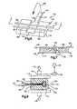
- FIG. 1is a schematic illustration depicting the relationship of a suture retainer to a suture and body tissue prior to tightening of the suture;
- FIG. 2is an enlarged sectional view illustrating the manner in which the suture is wrapped around the suture retainer of FIG. 1 to form bends in the suture;
- FIG. 3is a schematic illustration depicting the manner in which the suture retainer of FIG. 2 is pressed against body tissue with a predetermined force and the manner in which a predetermined force is applied to an outer side surface of the suture retainer to plastically deform the suture retainer;
- FIG. 4is an enlarged fragmentary schematic illustration of a portion of FIG. 3 and depicting the manner in which the material of the suture retainer grips the suture;
- FIG. 5is an enlarged fragmentary view of a portion of FIG. 4 further illustrating the manner in which the material of the suture retainer grips the suture;
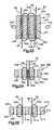
- FIG. 6is a schematic pictorial illustration depicting the manner in which a suture is positioned relative to a base of a second embodiment of the suture retainer
- FIG. 7is a schematic illustration, taken along the line 7 - 7 of FIG. 6 , depicting the manner in which a movable arm presses a portion of the suture into a groove formed in the base of the suture retainer to form bends in the suture;
- FIG. 8is a schematic illustration depicting the manner in which force is applied against the suture retainer of FIGS. 6 and 7 to plastically deform the suture retainer;
- FIG. 9is a schematic illustration depicting the manner in which a suture is wrapped around another embodiment of the suture retainer to form bends in the suture;
- FIG. 10is an enlarged fragmentary sectional view, taken generally along the line 10 - 10 of FIG. 9 , illustrating the manner in which the suture is disposed in a groove in the suture retainer;
- FIG. 11is a fragmentary sectional view, generally similar to FIG. 10 , illustrating an alternative configuration for the groove in the suture retainer of FIG. 9 ;
- FIG. 12is a schematic illustration depicting the manner in which force is applied against the suture retainer of FIG. 9 to plastically deform the suture retainer and grip the suture;
- FIG. 13is a schematic illustration depicting another embodiment of the suture retainer and the manner in which sections of a suture are wrapped in opposite directions to form bends in the suture;
- FIG. 14is a sectional view, taken generally along the line 14 - 14 of FIG. 13 , illustrating the manner in which the suture is disposed in a groove in the suture retainer;
- FIG. 15is an enlarged fragmentary schematic illustration of a portion of FIG. 13 , further illustrating the manner in which the suture is disposed in grooves formed in the suture retainer;
- FIG. 16is a fragmentary schematic sectional illustration of the manner in which the grooves and sections of the suture of FIG. 15 cross;
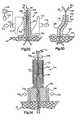
- FIG. 17is a schematic sectional view illustrating the manner in which a suture is wrapped around a roller in another embodiment of the suture retainer
- FIG. 18is a schematic illustration depicting the manner in which the suture retainer of FIG. 17 is urged toward body tissue and the manner in which force is applied against the suture retainer to plastically deform the suture retainer;
- FIG. 19is a fragmentary schematic illustration, generally similar to FIG. 17 , depicting an alternative manner of wrapping the suture around the roller;
- FIG. 20is a fragmentary schematic illustration of another embodiment of the suture retainer in which a housing encloses a plurality of cylinders around which the suture is wrapped;
- FIG. 21is a schematic illustration depicting the manner in which the suture zig-zags through passages in another embodiment of the suture retainer
- FIG. 22is a schematic sectional view, taken generally along the line 22 - 22 of FIG. 21 , further illustrating the manner in which the suture extends through the suture retainer;
- FIG. 23is a schematic sectional view depicting the manner in which the suture zig-zags through passages in another embodiment of the suture retainer;
- FIG. 24is a schematic sectional view illustrating the manner in which turns of a suture are wrapped in looped around another embodiment of the suture retainer
- FIG. 25is a schematic sectional view illustrating the manner in which turns of a suture are wrapped in looped around another embodiment of the suture retainer
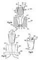
- FIG. 26is a schematic sectional view illustrating the manner in which a two-section embodiment of the suture retainer is positioned relative to body tissue prior to engagement of the two sections of the suture retainer;
- FIG. 27is a pictorial illustration of an inner or lower section of the suture retainer of FIG. 26 ;
- FIG. 28is a pictorial illustration of an outer or upper section of the suture retainer of FIG. 26 ;
- FIG. 29is a schematic sectional view of another two-section embodiment of the suture retainer prior to engagement of the two sections of the suture retainer;
- FIG. 30is a schematic illustration of another two-section embodiment of the suture retainer.
- FIG. 31is a pictorial illustration of an inner member used in the suture retainer of FIG. 30 ;
- FIG. 32is a schematic sectional illustration depicting the manner in which another embodiment of the suture retainer is pressed against a large area on body tissue with a predetermined force;
- FIG. 33is a schematic view of the suture retainer of FIG. 32 after the suture retainer has been plastically deformed to grip the suture;
- FIG. 34is a schematic illustration depicting the manner in which another embodiment of the suture retainer is pressed against body tissue and the manner in which force is applied against the suture retainer to effect plastic deformation of the suture retainer;
- FIG. 35is a schematic illustration of a tool which may be used to press the suture retainer of FIG. 13 against body tissue and to plastically deform the material of the suture retainer;
- FIG. 36is a schematic illustration of another embodiment of a tool which may be used to press a suture retainer against body tissue and to plastically deform the material of the suture retainer.
- a suture retainer 50( FIG. 1 ) is utilized to secure a known suture 52 against movement relative to body tissue 54 .
- the suture 52extends through an outer layer 56 and an inner layer 58 of the body tissue.
- the suture 52has been illustrated schematically in FIG. 1 as extending through passages 60 and 62 in the outer and inner layers 56 and 58 of body tissue 54 .
- the suture 52could be sewn through the body tissue without forming the passages 60 and 62 in the body tissue.
- suture 52has been shown in FIG. 1 in association with soft body tissue, it is contemplated that the suture 52 could be associated with hard body tissue. It is also contemplated that the suture 52 could extend through a suture anchor in a manner similar to that disclosed in U.S. Pat. Nos. 5,584,862; 5,549,631; and/or 5,527,343.
- the suture 52has a left section 66 and a right section 68 .
- the left and right sections 66 and 68 of the suture 62extend through the suture retainer 50 ( FIG. 2 ).
- the suture 52could be integrally formed as one piece with the suture retainer 50 . If this was done, an end of one of the sections 66 or 68 of the suture 52 would be connected with the suture retainer 50 .
- the sections 66 and 68 of the suture 52could extend straight through the suture retainer 50 , it is preferred to form a plurality of bends in the suture 52 .
- two bends 72 and 74( FIG. 2 ) are formed in the left section 66 of the suture 52 .
- two bends 76 and 78are formed in the right section 66 of the suture 52 .
- a greater or lesser number of bendscould be formed in each of the sections 66 and 68 of the suture 52 .
- the bends 72 and 74( FIG. 2 ) are formed in the left section 66 of the suture 52 by wrapping a turn 82 in the left section of the suture around a portion of the suture retainer 50 .
- the bends 76 and 78are formed in the right section 68 of the suture 52 by wrapping a turn 84 in the right section of the suture around a portion of the suture retainer 50 .
- a single loop 86is formed in the left section 66 of the suture 52 around a portion of the suture retainer.
- a single loop 88is formed in the right section 68 of the suture 52 around a portion of the suture retainer 50 .
- a greater or lesser number of loopscould be provided in the left and right sections 66 and 68 of the suture 52 if desired.
- the suture retainer 50has a spherical configuration.
- a cylindrical passage 92extends through the center of the spherical suture retainer 50 .
- the suture retainer 50could have a different configuration.
- the suture retainer 50could have an oval or elliptical configuration.
- the passage 92has a linear central axis, the passage could have a nonlinear central axis.
- a plurality of passages, having the same or different configurations,could be provided in the suture retainer 50 .
- the left and right sections 66 and 68 of the suture 52extend through the passage 92 .
- the left and right sections 66 and 68 of the suture 52extend around a spherical outer side surface 94 of the suture retainer 50 .
- the loop 86 in the left section 66 of the suture 52extends around a left (as viewed in FIG. 2 ) hemispherical portion of the suture retainer 50 .
- the loop 88extends around a right hemispherical portion of the suture retainer 50 .
- the left and right sections 66 and 68 of the suture 52engage the smooth spherical outer side surface 94 of the suture retainer 50 .
- groovescould be provided in the outside of the suture retainer 50 to receive the turns 82 and 84 of the left and right sections 66 and 68 of the suture 52 .
- projectionscould extend from the spherical outer side surface 94 of the suture retainer 50 to engage the suture 52 .
- the suture retainer 50is moved along the left and right sections 66 and 68 of the suture toward the body tissue 54 ( FIG. 1 ).
- the left and right sections 66 and 68 of the sutureare pulled upward (as viewed in FIGS. 1 and 2 ) to tension the sections of the suture.
- a downward (as viewed in FIG. 1 ) forceis then applied against the suture retainer 50 . This downward force causes the suture retainer 50 to slide in a downward direction along the suture 52 toward an upper side surface 98 of the body tissue 54 ( FIG. 1 ).
- the suture retainer 50is formed as one piece of a polymeric material having a relatively low coefficient of friction. Therefore, the two sections 66 and 68 of the suture 52 can readily slide along the outer side surface 94 and through the passage 92 in the suture retainer 50 as the suture retainer is moved downward toward the upper side surface 98 ( FIG. 1 ) of the body tissue 54 .
- the suture retainer 50While a predetermined tension is maintained in the left and right sections 66 and 68 of the suture 52 , the suture retainer 50 is pressed against the upper side surface 98 of the body tissue 54 ( FIG. 3 ). This results in a connector section 102 ( FIG. 1 ) of the suture 52 being pulled tightly against the inner layer 58 of body tissue.
- the suture retainer 50is pressed against the upper side surface 98 of the body tissue with a predetermined force, indicated schematically by an arrow 104 in the FIG. 3 .
- the suture retainer 50increases the surface area on the body tissue 54 against which force is applied.
- the suture retainer 50is slid downward (as viewed in FIG. 1 ) along the left and right sections of the suture.
- the suture retainer 50is pressed against the body tissue 54 with a predetermined force 104 ( FIG. 3 ) which is sufficient to obtain a desired tension in the left and right sections 66 and 68 and connector section 102 of the suture 52 .
- a desired forcewhich has been preselected, is applied against the body tissue 54 by the suture 52 and suture retainer 50 .
- a force distribution member or buttonmay be placed between the suture retainer and the upper surface 98 of the body tissue.
- a second force distribution member or buttonmay be placed between the connector section 102 of the suture and a lower side surface 108 ( FIG. 1 ) of the body tissue 54 . If this is done, the main area of engagement of the suture 52 with the body tissue 54 would be at the passages 60 and 62 .
- the suture retainer 50is plastically deformed to grip the left and right sections 66 and 68 of the suture.
- a pair of force application members 112 and 114are pressed against opposite sides of the suture retainer 50 . The force applied against the suture retainer 50 by the force application members 112 and 114 plastically deforms the material of the suture retainer.
- the plastic deformation of the suture retainer 50is effective to cause cold flowing of material of the suture retainer.
- Force indicated by arrows 118 and 120 in FIG. 3is applied against the suture retainer 50 by the force application members 112 and 114 .
- This forceis effective to cause flowing of the material of the suture retainer 50 at a temperature below a transition temperature range for the material of the suture retainer.
- the illustrated force application members 112 and 114have flat force transmitting surfaces, each of the force application members could have force transmitting surfaces with a configuration corresponding to the configuration of a portion of a sphere.
- the cold flowing of the material of the suture retainer 50results in a collapsing of the passage 92 ( FIG. 2 ) and in flowing of the material of the suture retainer 50 around the sections 66 and 68 of the suture 52 . This enables the material of the suture retainer 50 to bond to and obtain a firm grip on the suture 52 .
- the cold flowing of the material of the suture retainer 50occurs at a temperature which is below the transition temperature of the material forming the suture retainer.
- the material of the suture retainer 50flows around and grips the portion of the suture which was disposed in the passage 92 .
- the force applied against the turns 82 and 84 by the force application members 112 and 114is sufficient to embed the turns 82 and 84 of the suture 52 in the material of the suture retainer 50 to further grip the suture.
- the turns 82 and 84are disposed in grooves in the outside of the suture retainer, the material of the suture retainer would more firmly grip the portion of the suture 52 forming the turns 82 and 84 .
- groovescould be formed in the cylindrical side surface of the passage 92 to receive the sections 66 and 68 of the suture 52 .
- a transducer or load cell 114( FIG. 3 ) is connected with the force application member 112 to measure the amount of force, indicated by the arrows 118 and 120 , which is applied against the suture retainer 50 .
- a display unit 126is connected with the load cell 124 and provides an output indicative of the force being applied against opposite sides of the suture retainer 50 by the force application members 112 and 114 . After a predetermined minimum force has been applied against the suture retainer 50 for a predetermined minimum time by the force application members 112 and 114 , an output from the display unit 126 activates an indicator 130 to indicate to a surgeon that the desired plastic deformation of the suture retainer 50 has occurred. The force application members 112 and 114 can then be withdrawn from the suture retainer 50 .
- the suture retaineris pressed against the upper side surface 98 of the body tissue 54 with a predetermined force, indicated at 104 in FIG. 3 .
- a predetermined tensionis maintained in sections 66 and 68 of the suture 52 extending upward from the suture retainer 50 .
- the application of the clamping forces 118 and 120 against opposite sides of the suture retainer 50causes cold flowing of the material of the suture retainer.
- the material of the suture retainer 50moves between and extends around the portions of the left and right sections 66 and 68 of the suture 52 disposed in the passage 92 ( FIG. 2 ).
- a portion 134 ( FIGS. 2 and 4 ) and a portion 136 of the left section 66 of the suture 52are fully enclosed by the material of the suture retainer 50 .
- a cold bonding of the material of the suture retainer 50 with the exterior surfaces of the portions 134 , 136 of the left section 66 of the suture retainersecurely interconnects the material of the suture retainer and the suture 52 .
- the portions 138 and 140 of the right section 68 of the suture 52 disposed in the passage 92are surrounded by and bonded with the material of the suture retainer 50 ( FIG. 4 ).
- the manner in which the material of the suture retainer 50 extends completely around and is connected with the length or portion 138 of the right section 68 of the suture 52is illustrated schematically in FIG. 5 . It should be understood that the permanent deformation of the material of the suture retainer 50 occurs as a result of compression of the material of the suture retainer while the material is at a temperature close to the temperature of the body tissue 54 . This temperature is below the transition temperature for the material of the suture retainer 50 .
- the suturemay be knotted if desired.
- a knotmay be formed between the portions of the sections 66 and 68 of the suture 52 which extend upward (as viewed in FIGS. 1-3 ) from the retainer 50 .
- Such a knotwould provide additional protection against the suture working loose under the influence of varying loads over an extended period of time. Since the suture retainer 50 is disposed between the knot and the body tissue 54 , the knot will not reduce the overall force transmitting capability of the suture 52 . However, it is believed that forming a knot in the sections 66 and 68 of the suture 52 adjacent to the upper end of the suture retainer 50 will not be necessary.
- the suture retainer 50may be formed of many different materials. However, it is believed that it will be preferred to form the suture retainer 50 of a biodegradable polymer.
- a biodegradable polymerwhich may be utilized is polycaperlactone.
- the suture retainer 50could be formed of polyethylene oxide terephthalate or polybutylene terephthalate. It is also contemplated that other biodegradable or bioerodible copolymers could be utilized if desired.
- the suture retainer 50could be formed of a material which is not biodegradable.
- the suture retainercould be formed of an acetyl resin, such as “Delrin” (trademark).
- the suture retainer 50could be formed of a para-dimethylamino-benzenediazo sodium sulfonate, such as “Dexon” (trademark).
- the suture retainer 50could be heated to a temperature which is somewhat above the temperature of the body tissue 54 . If desired, heat could be transmitted to the suture retainer 50 through the force application members 112 and 114 ( FIG. 3 ). Although the suture retainer 50 may be heated, the suture retainer would be maintained at a temperature below the transition temperature for the material of the suture retainer.
- the suture 52is separate from the suture retainer 50 .
- one of the sections 66 or 68 of the suture 52could be fixedly connected with the suture retainer 50 . This could be accomplished with a suitable fastener or by forming the suture 52 integrally as one piece with the suture retainer. This would result in the suture retainer 50 sliding along only one of the sections 66 or 68 of the suture 52 .
- the suture 52may be formed of material or synthetic materials.
- the suture 52may be a monofilament or may be formed of a plurality of interconnected filaments.
- the suture 52may be biodegradable or nonbiodegradable. It may be preferred to form the suture 52 of the same material as the suture retainer 50 . However, the suture 52 could be formed of a material which is different than the material of the suture retainer.
- the use of the suture retainer 50eliminates the necessity of forming a knot in the suture 52 . By eliminating the formation of a knot in the suture 52 , the overall force transmitting capability of the suture is increased. In addition to increasing the overall force transmitting capability of the suture 52 , the suture retainer 50 increases the surface area on the body tissue 54 ( FIG. 1 ) against which force is applied by the suture. This tends to minimize any tendency for the suture 52 to cut or separate the body tissue.
- the left and right sections 66 and 68 of the suture 52may be wound around the suture retainer 50 before the suture is positioned in the passages 60 and 62 in the body tissue 54 .
- the left section 66 of the suture 52may be wound around the suture retainer 52 to form the bends 72 and 74 and the loop 86 ( FIG. 2 ) while the suture is spaced from the body tissue 54 .
- the right section 68 of the sutureis then inserted through the passages 60 and 62 ( FIG. 1 ) in the body tissue 54 .
- the right section 68 of the suture 52is then wound around the suture retainer 50 to form the bends 76 and 78 and loop 88 ( FIG. 2 ).
- complete loops 86 and 88are formed in the sections 66 and 68 of the suture 52 .
- partial loopsare formed in each of the sections of the suture. Since the embodiment of the invention illustrated in FIGS. 6-8 is similar to the embodiment of the invention illustrated in FIGS. 1-5 , similar terminology will be utilized to identify similar components. It should be understood that one or more features of the embodiment of the invention illustrated in FIGS. 1-5 may be used with the embodiment of the invention illustrated in FIGS. 6-8 .
- a suture retainer 150is utilized to secure a suture 52 against movement relative to body tissue.
- the suture 52has sections 66 and 68 which engage body tissue in the same manner as previously described in conjunction with the embodiment of the invention illustrated in FIGS. 1-5 .
- the suture 52is illustrated in FIG. 1 in association with soft body tissue, it is contemplated that the suture 52 could be utilized in association with hard body tissue and/or one or more suture anchors.
- the suture retainer 150includes a rectangular base or body section 152 and a movable post or locking section 154 .
- the post or locking section 154is integrally formed as one piece with the base 152 .
- the post or locking sectionis hingedly connected with the base 152 at a connection 156 .
- the post 154is pivotal relative to the base at the connection 156 in the manner indicated schematically by the arrow 158 in FIG. 6 .
- the base 152has a central groove 162 which is aligned with the post 154 .
- the groove 162has a rectangular cross sectional configuration.
- the groove 162has a cross sectional area which is greater than the cross sectional area of the post 154 .
- the post 154 and groove 162both have a rectangular cross sectional configuration.
- the post and groovecould have a different cross sectional configuration if desired.
- the post 154 and groove 162could have a semi-circular cross sectional configuration.
- the base 152has a pair of flat rectangular upper (as viewed in FIGS. 6 and 7 ) side surfaces 166 and 168 .
- the flat side surfaces 166 and 168extend in opposite directions from the groove 162 and extend parallel to a flat rectangular bottom surface 170 .
- the suture retainer 150is formed from a single piece of a biodegradable polymer, such as polycaperlactone. Of course, other biodegradable or bioerodible copolymers could be utilized to form the suture retainer 150 . It is contemplated that the suture retainer 150 may be formed of materials which are not biodegradable.
- the post 154When the suture retainer 150 is to be utilized to hold the sections 66 and 68 of the suture 52 against movement relative to body tissue, the post 154 is pivoted from its initial or extended position, shown in FIG. 6 , to its engaged or locking position, shown in FIG. 7 . As the post 154 is pivoted to the engaged position of FIG. 7 , a flat side surface 174 of the post is pressed against the sections 66 and 68 of the suture to force the sections into the groove 162 . The post is effective to clamp or hold the sections 66 and 68 of the suture 52 against movement relative to the base 152 upon movement of the post to the engaged position shown in FIG. 7 .
- the base 152is bent from the flat orientation of FIGS. 6 and 7 to the folded orientation of FIG. 8 .
- a pair of force application members 112 and 114engage opposite sides of the bottom or outer surface 170 of the base. The force application members 112 and 114 are then pressed toward each other, in the manner indicated schematically by the arrows 118 and 120 in FIG. 8 , to apply pressure against the suture retainer 150 .
- the suture retainer 150is at a temperature below the transition temperature of the material forming the suture retainer.
- the suture retainer 150is at a temperature which is approximately the same as the temperature of the body tissue relative to which the suture retainer 150 is being utilized to secure the suture 52 .
- the force applied against the suture retainer 150 by the force application members 112 and 114plastically deforms the material of the suture retainer. This results in a cold flowing of the material of the suture retainer 150 under the influence of the force applied against the suture retainer by the force application members 112 and 114 .
- a transducer or load cell 124measures the force 118 and 120 applied against the base 152 of the suture retainer 150 .
- the load cell 124provides an output signal to a display unit 126 .
- the output signal provided by the transducer 124corresponds to the magnitude of the force applied against opposite sides of the suture retainer 150 by the members 112 and 114 .
- an output signal from the display unit 126activates an indicator 130 .
- the output from the indicator 130indicates to a surgeon and/or other medical personnel that the force has been applied against opposite sides of the suture retainer 150 by the force application members 112 and 114 for a period of time sufficient to cause cold flowing of the material of the suture retainer.
- the cold flowing of the material of the suture retainer 150results in a secure interconnection between the material of the suture retainer 150 and the sections 66 and 68 of the suture 52 .
- the suture 52is separate from the suture retainer 150 .
- the suture 52could be fixedly connected to or integrally formed as one piece with the suture retainer 150 .
- the base 152could be integrally formed with the section 66 of the suture 52 if desired.
- the sections 66 and 68 of the suture 52extend through a passage formed in a spherical suture retainer 50 .
- the sections of the sutureextend along a groove formed in the outside of a suture retainer. Since the embodiment of the invention illustrated in FIGS. 9-12 is similar to the embodiment of the invention illustrated in FIGS. 1-5 , similar terminology will be utilized to identify similar components. It should be understood that one or more features of the embodiments of the invention illustrated in FIGS. 1-8 may be used with the embodiment of the invention illustrated in FIGS. 9-12 .
- a suture retainer 180( FIG. 9 ) is utilized to secure a suture 52 against movement relative to body tissue 54 .
- body tissue 54is soft body tissue, it is contemplated that the suture retainer 180 could be utilized to secure the suture 52 against movement relative to hard body tissue, such as bone.
- the suture retainer 180may be used either with or without a suture anchor.
- the suture retainer 180has a cylindrical main section or body 184 .
- the body 184has a cylindrical outer side surface 186 .
- Flat circular end surfaces 188 and 190extend perpendicular to a longitudinal central axis of the cylindrical side surface 186 .
- the body 184is cylindrical and has a linear longitudinal central axis. If desired, the body 184 could be rectangular and/or have a nonlinear longitudinal central axis.
- a helical groove 194is formed in the body 184 .
- the helical groove 194has a constant pitch. Therefore, turns of the groove 194 are equally spaced. However, if desired, the pitch of the turns of the groove 194 could vary along the length of the body 184 .
- the helical groove 194has a central axis which is coincident with the central axis of the body 184 and cylindrical outer side surface 186 of the suture retainer 180 .
- a radially inner portion of the helical groove 194defines a right circular cylinder which is coaxial with the outer side surface 186 of the body 184 .
- the radially inner portion of the helical groove 194could define a right circular cone or other configuration if desired.
- the left and right sections 66 and 68 of the suture 52extend through the groove 194 and around body tissue 54 . It is believed that it will be advantageous to provide the helical groove 194 with retainers or bridge sections 198 and 200 which extend across the open ends of the helical groove.
- the bridge sections 198 and 200are integrally formed as one piece with the body 184 .
- the bridge sections 198 and 200prevent the sections 66 and 68 of the suture 52 from pulling out of the helical groove 194 during positioning of the suture retainer 180 in a human patient's body. However, the bridge sections 198 and 200 may be omitted if desired.
- the helical groove 194has a generally U-shaped cross sectional configuration ( FIG. 10 ).
- the helical groove 194has an open mouth or entrance 204 .
- a pair of side surfaces 206 and 208slope radially inward and axially upward (as viewed in FIGS. 9 and 10 ) from the entrance 204 .
- An arcuate bottom surface 210 of the groove 194extends between the side surfaces 206 and 208 .
- the section 66 of the suture 52is disposed in engagement with the bottom surface 210 of the helical groove 194 .
- the section 68 of the suture 52is disposed in engagement with the section 66 of the suture ( FIG. 10 ). If desired, the size of the arcuate bottom surface 210 of the groove 194 could be increased to enable both sections 66 and 68 of the suture 52 to engage the bottom surface.
- the groove 194may be provided with a configuration similar to the configuration shown in FIG. 11 .
- the side surfaces 206 and 208 of the helical groove 194extend inward from the open entrance 204 to an arcuate bottom surface 210 which forms a major portion of a circle.
- the bottom surface 210 of FIG. 11defines a recess 214 in which the two sections 66 and 68 of the suture are disposed. It is believed that the bridge sections 198 and 200 will probably be omitted with the embodiment of the groove 194 illustrated in FIG. 11 .
- the cylindrical body 184 of the suture retainer 180is molded from a single piece of a biodegradable polymer.
- the body 184 of the suture retainer 180may be molded from polycaperlactone.
- the body 184 of the suture retainer 180could be molded of polyethylene oxide terephthalate or polybutylene terephthalate.
- the body 184 of the suture retainer 180could be molded as one piece of other biodegradable or bioerodible copolymers if desired.
- the body 184 of biodegradable materialsthe body could be formed of materials which are not biodegradable.
- the body 184could be formed of “Delrin” (trademark).
- the left and right sections 66 and 68 ( FIG. 9 ) of the suture 52are inserted into the helical groove 194 in the body 184 of the suture retainer 180 .
- the body 184 of the suture retainer 180is spaced from the body tissue 54 . It is believed that insertion of the left and right sections 66 and 68 of the suture 52 into the helical groove 194 will be facilitated if the bridge sections 198 and 200 are omitted. However, if the bridge sections 198 and 200 are omitted, difficulty may be encountered in maintaining the sections 66 and 68 of the suture 52 in the helical groove 194 .
- the sections of the suture 52are wrapped around the body 184 of the suture retainer 180 . As this occurs, a plurality of helical loops are formed in the left and right sections 66 and 68 of the suture 52 .
- a plurality of circular turnsare maintained in the left and right sections 66 and 68 of the suture 52 by the helical groove 194 . Therefore, a continuous series of smooth arcuate bends, which are free of stress inducing discontinuities, is maintained in the suture 52 by the helical groove 194 .
- the suture retainer 180is moved along the suture toward the body tissue 54 ( FIG. 9 ). During this movement of the suture retainer 180 along the suture 52 , the left and right sections 66 and 68 of the suture are tensioned.
- the radially inward and axially upward sloping configuration of the helical groove 194results in the left and right sections 66 and 68 of the suture being pulled toward the arcuate bottom surface 210 of the groove.
- the left and/or right sections 66 and 68 of the suture 52slide along the arcuate bottom surface 210 ( FIG. 10 ) of the groove 194 .
- the groove 194imparts a helical configuration to the portion of the suture 52 disposed in the groove.
- the portion of the suture 52 having a helical configurationmoves downward toward the body tissue.
- the biodegradable copolymer forming the body 184 of the suture retainer 180has a low coefficient of friction. This minimizes the force 220 required to move the suture retainer along the left and right sections 66 and 68 of the suture 52 toward the body tissue 54 .
- the suture retainer 180is moved along the taut left and right sections 66 and 68 of the suture 52 until the leading end surface 190 of the body 184 of the suture retainer 180 engages the body tissue 54 ( FIG. 9 ).
- the force 220is then increased to a predetermined magnitude while maintaining a predetermined tension in the left and right sections 66 and 68 of the suture 52 . This results in the suture 52 being pulled tightly around the body tissue and exerting a predetermined force against the body tissue.
- the magnitude of the force 220 ( FIG. 9 ) with which the suture retainer 190 is pressed against the body tissue 54will be measured to be certain that the force has a desired magnitude.
- the force 220may be measured with a suitable transducer, such as a load cell or a force measuring device having a spring which is compressed to a predetermined extent by the application of the desired force against the body tissue 54 .
- a suitable force transmitting membersuch as a button, could be provided between the suture retainer and the body tissue.
- the left and right sections 66 and 68 of the suture 52are gripped by plastically deforming the material of the suture retainer.
- a plurality of force application members 224 , 226 and 228( FIG. 12 ) are pressed against the cylindrical outer side surface 186 of the suture retainer 180 . Since the outer side surface 186 of the suture retainer 180 has a cylindrical configuration, the force application members 224 , 226 and 228 have an arcuate configuration and are formed as portions of a circle. However, the force application members 224 , 226 and 228 could have the flat configuration of the force application members 112 and 114 of FIG. 3 .
- the force application members 224 , 226 and 228are pressed against the outer side surface 186 of the suture retainer 180 with a predetermined force, indicated by the arrows 232 in FIG. 12 .
- This forcehas a magnitude and is applied for a length of time sufficient to cause cold flowing of the material of the body 184 of the suture retainer 180 .
- the plastic deformation of the material of the body 194 of the suture retainer 180results in the helical groove 194 being collapsed and the, material of the suture retainer being pressed against the left and right sections 66 and 68 of the suture 52 .
- the resulting cold bonding of the material of the suture retainer 180 with the left and right sections 66 and 68 of the suture 52secures in the suture retainer against movement relative to the suture.
- the cold flowing of the material of the body 184 of the suture retainer 180occurs with the body of the suture retainer at substantially the same temperature as the temperature of the body tissue 54 ( FIG. 9 ).
- the cold flowing of the material of the body 184 of the suture retainer 180occurs at a temperature below the transition temperature of the material forming the body 184 of the suture retainer 180 .
- some heatmay be added to the body 184 to facilitate plastic deformation of the body of the suture retainer 180 .
- the suture retainer 180eliminates the necessity of forming a knot in the suture 52 .
- the formation of a knot in the suture 52would cause a stress concentration in the suture and would decrease the overall force transmitting capability of the suture. By eliminating the knot, the overall force transmitting capability of the suture 52 is increased.
- a knotcould be formed in the sections 66 and 68 of the suture 52 at a location above (as viewed in FIG. 1 ) the suture retainer 180 . Since the suture retainer 180 would be disposed between this knot and the body tissue 54 , the knot would not decrease the overall force transmitting capability of the suture 52 .
- a single helical groove 194is formed in the body 184 of the suture retainer 180 . It is contemplated that a pair of spaced apart helical grooves could be formed in the body 184 of the suture retainer 180 . If this was done, the two helical grooves would be wrapped in the same direction around the body 184 of the suture retainer 180 and would be offset from each other by 180° about the circumference of the cylindrical body of the suture retainer. The left section 66 of the suture 52 would be disposed in one of the helical grooves and the right section 68 of the suture would be disposed in the other helical groove.
- the left and right sections 66 and 68 of the suture 52would exit from the lower (as viewed in FIG. 9 end of the suture retainer at diametrically opposite locations on the circular end surface 190 .
- This embodiment of the suture retainer 180would have the advantage of having a relatively large area of engagement with the body tissue 54 . Thus, the tension in the suture would press the flat circular end surface 190 on the suture retainer against the body tissue.
- the suture 52is separate from the suture retainer 180 .
- the suture 52could be fixedly connected with or integrally formed as one piece with the suture retainer.
- the left section 66 of the suture 52could be fixedly connected with the body 184 of the suture retainer 180 by a suitable fastener. If this was done, only the right section 68 of the suture 52 would be received in the groove 194 .
- the left and right sections 66 and 68 of the suture 52are wrapped in the same direction around the cylindrical body 184 of the suture retainer 180 .
- the sections of the sutureare wrapped in opposite directions around a conical body of a suture retainer. Since the embodiment of the invention illustrated in FIGS. 13-16 is similar to the embodiment of the invention illustrated in FIGS. 9-12 , similar terminology will be utilized to identify similar components. It should be understood that one or more features of the embodiments of the invention illustrated in FIGS. 1-12 may be used with the embodiments of the invention illustrated in FIGS. 13-16 .
- a suture 52( FIG. 13 ) has left and right sections 66 and 68 which are wrapped in opposite directions around a conical body 242 of a suture retainer 244 .
- the left section 66 of the suture 52is wrapped in a counterclockwise direction around the body 242 of the suture retainer 244 .
- the right section 68 of the suture 52is wrapped in a clockwise direction around the body 242 of the suture retainer 244 .
- the left and right sections 66 and 68 of the suture 52are wrapped for approximately 11 ⁇ 2 turns around the body 242 of the suture retainer 244 . Therefore, the left section 66 of the suture 52 moves from the left side of the upper end (as viewed in FIG. 13 ) of the body 242 of the suture retainer 244 to the right side of the lower end of the body of the suture retainer. Similarly, the right section 68 of the suture 52 moves from the upper right side of the body 242 of the suture retainer 244 to the lower left side of the body of the suture retainer.
- the sections of the suture 52would be on the same side of the body 242 at the top and bottom of the suture retainer.
- the left section 66 of the suture 52would be disposed at the left side of both the upper and lower ends of the body 242 .
- the right section 68 of the suture 52could be disposed at the right side of both the upper and lower ends of the body 242 of the suture retainer.
- the body 242 of the suture retainer 244is formed as a portion of a right circular cone.
- the body 242 of the suture retainer 244has an outer side surface 248 with an axially downward (as viewed in FIG. 13 ) and radially inward tapering configuration.
- the conical body 242 of the suture retainer 244has parallel circular end surfaces 252 and 254 which extend perpendicular to a longitudinal central axis of the conical body.
- the circular end surfaces 252 and 254are disposed in a coaxial relationship.
- the upper end surface 252has a larger diameter than the lower end surface 254 .
- a pair of helical grooves 258 and 260are formed in the conical body 242 .
- the helical grooves 258 and 260have a spiral configuration with a central axis which is coincident with the central axis of the conical body 242 .
- the diameter of the turns of the grooves 258 and 260progressively decreases as the grooves extend downward (as viewed in FIG. 13 ) from the upper end surface 252 to the lower end surface 254 .
- the helical grooves 258 and 260have the same pitch.
- the helical grooves 258 and 260are wrapped in opposite directions around the conical body 242 of the suture retainer 244 .
- the helical groove 258is wrapped in a counterclockwise direction around the body 242 of the suture retainer 244 .
- the helical groove 260is wrapped in a clockwise direction around the body 242 of the suture retainer 244 .
- the helical grooves 258 and 260are offset by 180°. Thus, the helical groove 258 beings at the upper left (as viewed in FIG. 13 ) side of the body 242 and the helical groove 260 begins at the upper right side of the body 242 .
- the entrances to the helical grooves 258 and 260are disposed at diametrically offset locations on the circular upper end surface 252 of the body 242 .
- the helical groove 258ends at the lower right (as viewed in FIG. 13 ) side of the body 242 .
- the helical groove 260ends at the lower left side of the body 242 .
- the exits from the helical grooves 258 and 260are disposed at diametrically offset locations on the circular lower end surface 254 of the body 242 . This results in the relatively large lower end surface 254 of the body 242 being disposed between the left and right sections 66 and 68 of the suture 52 and exposed to body tissue.
- the groove 258has an axially upward and radially inward sloping configuration ( FIG. 14 ).
- the groove 258has a helical open mouth or entrance 264 .
- the groove 258has a pair of axially upward and radially inward sloping side surfaces 266 and 268 .
- the side surfaces 266 and 268are interconnected by an arcuate bottom surface 270 .
- the groove 258has the same depth and cross sectional configuration throughout the extent of the groove.
- the groove 260has the same cross sectional configuration as the groove 258 .
- the two grooves 258 and 260extend between the opposite end surfaces 252 and 254 of the conical body 242 . It is contemplated that the grooves 258 and 260 could have a different cross sectional configuration if desired. For example, the grooves 258 and 260 could have the cross sectional configuration shown in FIG. 11 if desired.
- the grooves 258 and 260intersect on opposite sides of the conical body 242 in the manner illustrated in FIGS. 15 and 16 . At the intersections between the grooves 258 and 260 , the left and right sections 66 and 68 of the suture 52 overlap ( FIG. 16 ). The number of intersections of grooves 258 and 260 will vary as a direct function of the number of turns of the grooves 258 and 260 around the body 242 .
- Bridge sections 274 and 276are provided across opposite ends of the groove 258 to facilitate in retaining the suture section 66 in the groove.
- bridge sections 278 and 280are provided across opposite ends of the groove 260 to facilitate in retaining the suture section 68 in the groove 260 . If desired, the bridge sections 274 , 276 , 278 and 280 could be omitted.
- the suture retainer 244includes a cylindrical sleeve 284 ( FIG. 13 ).
- the tubular sleeve 284has a cylindrical outer side surface 286 and a conical inner side surface 288 .
- the inner and outer side surfaces 286 and 288are disposed in coaxial relationship.
- the conical inner side surface 288 of the sleeve 284tapers axially inward and downward (as viewed in FIG. 13 ) at the same angle as does the conical outer side surface 248 of the body 242 .
- the conical inner side surface 288 of the sleeve 284has been schematically illustrated in FIG. 13 as having an inside diameter which is greater than the outside diameter of the conical body 242 , it is contemplated that the conical body 242 will have substantially the same diameter as the inner side surface 288 of the sleeve 284 . Therefore, when the circular end surface 252 on the conical body 242 is axially aligned with an annular end surface 292 on the sleeve 284 (as shown in FIG. 13 ), the outer side surface 248 on the conical body 242 will be disposed in abutting engagement with the inner side surface 288 on the sleeve 286 .
- the conical body 242 and the sleeve 284are both formed of a biodegradable polymer, such as polycaperlactone.
- the conical body 242 and the sleeve 284could be formed of polyethylene oxide terephthalate or polybutylene terephthalate if desired.
- Other biodegradable or bioerodible copolymerscould be utilized if desired. It is contemplated that it may be desired to form the conical body 242 and sleeve 284 of a polymer which is not biodegradable.
- the conical body 242 and sleeve 284could be formed of two different materials if desired.
- the left and right sections 66 and 68 of the sutureare first inserted through the open center of the sleeve 284 .
- the sections 66 and 68 of the suture 52are then wrapped around the conical body 242 in the grooves 258 and 260 .
- the sleeve 284may then be moved along the suture 252 to the desired position in a patient's body.
- the left and right sections 66 and 68 of the suture 52may be wound around the body 242 and inserted through the sleeve 284 before the suture is positioned relative to the body tissue. After the suture 52 has been positioned relative to the body tissue, the other section of the suture would be inserted through the sleeve 284 and wound around the body 242 .
- the sections 66 and 68 of the suture 52are tensioned as a force 296 ( FIG. 13 ) is applied to the conical body 242 .
- the force 296is sufficient to cause the conical body 242 of the suture retainer 244 to slide axially along the sections 66 and 68 of the suture toward the sleeve 284 .
- the outer side surface 248 on the conical body 242moves into engagement with the inner side surface 288 on the sleeve 284 .
- the force 296is then effective to press the outer side surface 248 on the conical body 242 firmly against the inner side surface 288 of the sleeve.
- the force 296is also effective to press both the end surface 254 of the conical body 242 and an annular end surface 300 of the sleeve 284 against the body tissue. While the left and right sections 66 and 68 of the suture are tensioned, the force 296 is increased. After the suture retainer 244 has been pressed against the body tissue with a predetermined force 296 sufficient to cause the suture 52 to grip the body tissue with a desired tension, force applicator members, similar to the force applicator members 224 , 226 and 228 of FIG. 12 , compress the sleeve 284 . The manner in which force is applied against the sleeve 284 is indicated schematically by arrows 302 and 304 in FIG. 13 . If desired, one or more axial slot may be provided through a portion of the sleeve 284 to facilitate compression of the sleeve.
- the force applied against the sleeve 284causes radially inward plastic deformation of the sleeve. This force is transmitted through the sleeve to the conical body 242 .
- the force transmitted to the conical body 242causes a collapsing of the grooves 258 and 260 . As the grooves 258 and 260 collapse, the material of the conical body 242 is plastically deformed and firmly grips or bonds to the outer side surfaces of the left and right sections 66 and 68 of the suture 52 .
- the sleeve 284bonds to the material of the conical body 242 .
- the sleeve 284 and conical body 242 of the suture retainer 244are at a temperature below the transition temperature of the material forming the sleeve and conical body when they are compressed by the force indicated schematically at 302 and 304 in FIG. 13 . This results in cold flowing of the material of both the sleeve 284 and the suture retainer 244 under the influence of the force 302 and 304 .
- the force 302 and 304is maintained at a predetermined magnitude for a time sufficient to result in cold plastic deformation of the material of the sleeve 284 and conical body 242 .
- This plastic deformation or cold flow of the material of the sleeve 284 and conical body 242occurs at a temperature which is substantially the same as the temperature of the body tissue with which the suture 52 is connected.
- both the conical body 242 and sleeve 284are at a temperature below the transition temperature of the material of the conical body and sleeve.
- the suturemay be knotted.
- a knotmay be formed in the upper (as viewed in FIG. 13 ) end portions 66 and 68 of suture 52 .
- the knotwould pull the sections 66 and 68 of the suture firmly against the upper side surface 252 of the conical body 242 .
- This knotwould not decrease the overall force transmitting capability of the suture 52 since the suture retainer 244 would be disposed between the knot and the body tissue. Although such a knot would provide additional assurance that the suture will not work loose, it is believed that the knot is not necessary.
- the tension in the suture 52will press the annular end surface 300 on the sleeve 284 and the circular end surface 254 on the conical body 242 against the body tissue. Due to the relative large combined area of the end surfaces 254 and 300 , the tension forces in the suture 52 will be applied to a relatively large area on the body tissue by the suture retainer 244 . Since the suture retainer 244 applies force to a relatively large surface area on the body tissue and since the overall strength of the suture 52 is not impaired by the suture retainer 244 , relatively large forces can be transmitted through the suture to the body tissue.
- the helical grooves 258 and 260cross. This results in the left and right sections 66 and 68 of the suture 52 being disposed in overlapping engagement at the intersections between the grooves 258 and 260 .
- the overlapping engagement of the left and right sections 66 and 68 of the suture 52increases the resistance of the suture retainer 244 to slipping of one section of the suture relative to the other section of the suture.
- the central axis of the conical body 242 of the suture retainer 244extends along the sections 66 and 68 of the suture 52 .
- a central axis of a circular body of the suture retainerextends transverse to the longitudinal axis of the suture during movement of the suture retainer toward the body tissue. Since the suture retainer of the embodiments of the invention illustrated in FIGS. 17-19 is similar to the suture retainer of the embodiment of the invention illustrated in FIGS. 13-16 , similar terminology will be utilized to identify similar components. It should be understood that one or more features of the embodiments of the invention illustrated in FIGS. 1-16 may be used with the embodiments of the invention illustrated in FIGS. 17-19 .
- a suture retainer 312( FIGS. 17 and 18 ) includes a cylindrical housing 314 and a rotatable cylinder 316 .
- the housing 314encloses the rotatable cylinder 316 .
- the rotatable cylinder 316has a central axis which is coincident with the central axis of the cylindrical housing 314 .
- the cylinder 316is supported for rotation relative to the housing 314 by bearing sections 320 and 322 ( FIG. 17 ).
- the bearing sections 320 and 322are integrally formed as one piece with the housing 314 .
- the bearing sections 320 and 322have a conical configuration and engage conical recesses formed in opposite ends of the rotatable cylinder 316 .
- the bearing sections 320 and 322support the cylinder 316 in a coaxial relationship with the housing 314 .
- Left and right sections 66 and 68 of the suture 52extend into the housing 314 through cylindrical openings 326 and 328 .
- the sections 66 and 68 of the suture 52extend from the housing 314 through openings 330 and 332 .
- the openings 326 , 328 , 330 and 332have parallel central axes which extend tangentially to the cylinder 316 .
- the left section 66 of the suture 52extends through the opening 326 into the housing 314 .
- the left section 66 of the suture 52is wrapped in a clockwise direction (as viewed in FIG. 18 ) around the cylinder 316 and extends from the housing 314 through the opening 330 .
- the right section 68 ( FIG. 17 ) of the suture 52extends into the housing 314 through the opening 328 .
- the right section 68 of the suture 52is wrapped in a counterclockwise direction, as viewed in FIG. 18 , around the cylinder 316 .
- the turns in the left and right sections 66 and 68 in the suture 52are axially spaced apart along the cylindrical outer side surface of the cylinder 316 . If desired, helical grooves may be provided in the cylinder 316 to receive the turns of the left and right sections 66 and 68 of the suture.
- the cylindrical housing 314is formed of a biodegradable polymeric material.
- the cylinder 316is also formed of a biodegradable polymeric material.
- the material of the cylinder 316is harder than the material of the housing 314 .
- the material of the cylinder 316has a lower coefficient of friction than the material of the housing 314 .
- the material of the housing 314is easier to plastically deform than the material of the cylinder 316 .
- the housing and cylinder 314 and 316may be formed of the same material which may be biodegradable (polycaperlactone) or may not be biodegradable.
- the suture retainer 312When the suture retainer 312 is to be positioned relative to body tissue (not shown), the left and right sections 66 and 68 of the suture are tensioned. The housing 312 is then pushed downward (as viewed in FIGS. 17 and 18 ) in the manner indicated schematically by an arrow 336 in FIG. 18 . As this occurs, the turns or wraps of the sections 66 and 68 of the suture slide along a cylindrical outer side surface of the rotatable cylinder 316 . The oppositely wound loops in the sections 66 and 68 of the suture 52 move downward along the suture toward the body tissue as the retainer 312 moves downward along the suture toward the body tissue.
- the position of the cylinder 316 relative to the housing 314remains substantially constant during a major portion of the movement of the suture retainer 312 along the suture 52 toward the body tissue. This is because the left and right sections 66 and 68 of the suture are wrapped in opposite directions around the cylinder 316 . This results in the portion of the loop in the left section 66 of the suture tending to rotate the cylinder 316 in a counterclockwise direction (as viewed in FIG. 18 ). At the same time, the loop formed in the right section 68 of the suture 52 tends to rotate the cylinder 316 in a clockwise direction (as viewed in FIG. 18 ).
- the tensionis maintained in the sections 66 and 68 of the suture 52 .
- the force 336FIG. 18 ) pressing the suture retainer 312 against the body tissue is increased.
- the suture retainer 312is pressed against the body tissue with a force, indicated schematically by the arrow 336 in FIG. 18 , which is sufficient to provide a desired tension in the portion of the suture 52 engaging the body tissue.
- the material of the suture retainer 312is then plastically deformed.
- the plastic deformation of the suture retainer 312is accomplished by applying force against opposite sides of the housing 314 with a pair of force application members 340 and 342 ( FIG. 18 ).
- the force applied against the suture retainer 312 by the force application members 340 and 342presses the material of the housing 314 against the sections 66 and 68 of the suture and the cylinder 316 by cold flowing material of the housing.
- a large gaphas been shown between the cylindrical outer side surface of the cylinder 316 and a cylindrical inner side surface of the housing 314 in FIG. 18 .
- this annular gapwill be relatively small so that the material of the housing 314 can readily cold flow into engagement with the turns of the sections 66 and 68 of the suture 52 and cylinder 316 .
- the force applied against the housing 314also plastically deforms and causes cold flowing of the material of the cylinder 316 to provide a secure bond or grip between the material of the cylinder 316 and the suture 52 .
- a transducer or load cell 346is associated with the force application member 342 and provides an output to a display unit 348 . After a predetermined minimum force has been applied to the suture retainer 312 by the force application members 340 and 342 for a predetermined minimum length of time, an output from the display unit 348 to an indicator 350 activates the indicator to provide a signal that the desired plastic deformation of the suture retainer 312 has been obtained.
- a knotmay be tied between the left and right sections 66 and 68 of the suture 52 adjacent to a side of the housing 314 opposite from a side of the housing which is pressed against the body tissue by the suture. The knot would be pulled tight against the housing at a location between the openings 326 and 328 . Since the suture retainer 312 is between the knot and the body tissue, the knot would not impair the force transmitting capability of the suture 52 .
- the sections 66 and 68 of the suture 52are wrapped in opposite directions around the cylinder 316 . This results in offsetting forces being applied to the cylinder 316 by the turns in the sections 66 and 68 of the suture 52 during movement of the suture retainer 312 along the suture toward the body tissue.
- the left and right sections 66 and 68 of the suture 52are wrapped in the same direction around the cylinder 316 . This results in the turns or loops in the sections 66 and 68 of the suture 52 applying force to the cylinder 316 urging the cylinder to rotate in the same direction during movement of the suture retainer 312 along the sections 66 and 68 of the suture toward body tissue. Therefore, when the sections 66 and 68 of the suture 52 are wrapped in the same direction around the cylinder 316 , the cylinder will freely rotate relative to the housing 314 as the suture retainer 312 is moved along the suture 52 toward the body tissue.
- the overall force transmitting capability of the suture 52is not impaired by the suture retainer 312 . This is because the turns of the loops formed in the left and right sections of the suture 52 around the cylinder 316 do not form stress concentrations in the suture. If a knot had been used to interconnect the left and right sections 66 and 68 of the suture 52 , in the manner taught by the prior art, the resulting stress concentration would reduce the overall force transmitting capability of the suture 52 .
- the cylindrical housing 314increases the surface area on body tissue against which force is applied by tension in the suture 52 after the suture retainer 312 has been plastically deformed to grip the suture. This increases the amount of force which may be transmitted through the suture 52 without damaging the body tissue.
- the cylinder 316is rotatable relative to the housing 314 .
- cylindersare fixedly connected with the housing. Since the embodiment of the invention illustrated in FIG. 20 is similar to the embodiment of the invention illustrated in FIGS. 17-19 , similar terminology will be utilized to identify similar components. It should be understood that one or more features of the embodiments of the invention illustrated in FIGS. 1-19 may be used with the embodiment of the invention illustrated in FIG. 20 .
- a suture retainer 356includes a rectangular housing 358 which encloses a plurality of cylinders 360 , 362 , 364 and 366 .
- the cylinders 360 - 366have parallel central axes which extend parallel to flat rectangular upper and lower side walls 370 and 372 of the housing 358 . Opposite end portions of the cylinders 360 - 366 are fixedly connected with rectangular end walls (not shown) of the housing 358 .
- the central axes of the cylinders 360 - 366extend perpendicular to the housing end walls to which the cylinders are fixedly connected.
- the cylinders 360 - 366are formed of a biodegradable material which is relatively hard.
- the housing 358is formed of a biodegradable material which is relatively soft. By forming the housing 358 of a biodegradable material which is relatively soft, plastic deformation of the housing is facilitated.
- the relatively hard biodegradable material forming the cylinders 360 - 366has a low coefficient of friction. Although it is preferred to form the cylinders 360 - 366 and housing 358 of biodegradable materials having different hardnesses, the cylinders and housing could be formed of biodegradable or nonbiodegradable materials having the same hardness if desired.
- a suture 52has left and right sections 66 and 68 which are wrapped around the cylinders 360 - 366 in a zig-zag fashion.
- the left section 66 of the suture 52is looped around the cylinders 360 and 362 .
- the right section 68 of the suture 52is looped around the cylinders 364 and 366 .
- the cylinders 360 and 362maintain a pair of smooth, continuous bends in the left section 66 of the suture 52 .
- the cylinders 364 and 366maintain a pair of smooth, continuous bends in the right section 68 of the suture 52 .
- the smooth, continuous bends in the sections 66 and 68 of the suture 52are free of stress inducing discontinuities. If desired, a greater or lesser number of bends could be maintained in the sections 66 and 68 of the suture 52 by a greater or lesser number of cylinders.
- FIG. 20there is a single partial turn of the left section 66 of the suture around each of the cylinders 360 and 362 .
- a plurality of turns or loopscould be provided around each of the cylinders 360 - 366 by the sections 66 and 68 of the suture 52 .
- the left section 66 of the suture 52could be wrapped for one complete revolution around the cylinder 360 and then wrapped for a partial revolution around the cylinder 360 before extending to the cylinder 362 .
- the right section 68 of the suture 52could be wrapped for one complete revolution around the cylinder 366 and then wrapped for a partial revolution around the cylinder 364 before exiting from the housing 358 .
- the suture retainer 356is moved along the sections 66 and 68 of the suture 52 toward body tissue.
- the housing 358is moved downward (as viewed in FIG. 20 ) toward the body tissue, the left and right sections 66 and 68 of the suture 52 slide along the outer side surfaces of the cylinders 360 - 366 .
- the cylinders 360 - 366cooperate to maintain a plurality of bends in each of the sections 66 and 68 of the suture 52 .
- the housing 358is plastically deformed to grip the suture 52 .
- forceindicated by arrows 380 and 382 in FIG. 20 supplied against a side of the housing 358 opposite from the force 376 . This force is effective to plastically deform the material of the housing and to press the material of the housing against the cylinders 360 - 366 and against the sections 66 and 68 of the suture 52 .
- the material of the housingcold flows under the influence of the force.
- This cold flow of the material of the housingresults in the left and right sections 66 and 68 of the suture being firmly pressed against the cylinders 360 - 366 to form a solid bond with the left and right sections 66 and 68 of the suture 52 .
- the material forming the cylinders 360 - 366is relatively hard, compared to the material forming the housing 358 , the housing will deform to a greater extent than the cylinders during cold flow of the material of the housing. However, there will be some plastic deformation of the cylinders 360 - 366 .
- the force transmitting capability of the suture 52is enhanced by minimizing stress concentrations in the suture and by transmitting force from the housing 358 to a large area on the body tissue.
- the bends formed in the suture 52 around the cylinders 360 - 366are free of abrupt stress inducing discontinuities.
- the housing 358transmits force to the body tissue located between the opposite sides of the left and right sections 66 and 68 of the suture 52 . Therefore, stress concentrations in both the body tissue and the suture 52 tend to be minimized.
- a knotmay be tied between the upper (as viewed in FIG. 20 ) end portions of the left and right sections 66 and 68 of the suture 52 . Although such a knot would provide additional assurance that the suture 52 will not work loose, it is believed that the knot will not be necessary.
- One of the ends of the suturecould be fixedly connected with the housing 358 . This could be done by forming the suture 52 as one piece with the housing 358 or by using a fastener. If one end of the suture is fixedly connected with the housing 358 , one of the sets of cylinders, for example, the cylinders 360 and 362 , could be eliminated.
- bendsare formed in the left and right sections 66 and 68 of the suture 52 by circular surfaces.
- the bendsare formed in the suture by passages through a rectangular member. Since the embodiment of the invention illustrated in FIGS. 21 and 22 is similar to the embodiment of the invention illustrated in FIGS. 9-20 , similar terminology will be utilized to identify similar components. It should be understood that one or more of the features of the embodiments of the invention illustrated in FIGS. 1-20 may be used with the embodiment of the invention illustrated in FIGS. 21-22 .
- a suture retainer 390is formed in a single rectangular piece of biodegradable material.
- the suture retainer 390includes a rectangular body 392 formed of a suitable biodegradable material.
- the rectangular body 392could be formed of a non-biodegradable material if desired.
- a plurality of parallel passages 394 , 396 and 398extend between opposite parallel rectangular end surfaces 400 and 402 of the body 392 .
- the left and right sections 66 and 68 of the suture 52zig-zag through the passages 394 , 396 and 398 in a side-by-side relationship.
- the sections 66 and 68 of the suture 52zig-zag through the passages 394 , 396 and 398 to form a series of bends in the suture.
- the passages 394 , 396 and 398 in the body 392 of the suture retainer 390cooperate to form smooth, continuous bends 406 , 408 , 410 and 412 ( FIG. 21 ) in the sections 66 and 68 of the suture 52 .
- the left and right sections 66 and 68 of the suture 52extend through the straight passage 394 .
- Bends 406 and 408are formed in the portions of the sections 66 and 68 of the suture disposed between the passage 394 and the passage 396 .
- bends 410 and 412are formed in the sections 66 and 68 of the suture 52 disposed between the passages 396 and 398 .
- additional bendswould be formed in the suture 52 .
- the bends 406 - 412 in the sections 66 and 68 of the suture 52are smooth and free of stress inducing discontinuities. By keeping the suture 52 free of stress inducing discontinuities, the force which can be transmitted through the suture tends to be maximized. If a knot was substituted for the suture retainer 390 , stress concentrations would be formed and the force transmitting capability of the suture reduced.
- the passage 394has a main section 418 and a gripping section 420 .
- the gripping section 420has a tapered configuration ( FIG. 22 ) and extends sideward from the main section 418 .
- the left and right sections 66 and 68 of the suture 52may be pulled from the main section 418 of the passage 394 into the gripping section 420 of the passage. As this occurs, the side surfaces of the passage 394 grip opposite sides of the left and right sections 66 and 68 of the suture 52 to hold the left and right sections of the suture against axial movement relative to the rectangular body 392 of the suture retainer 390 .
- the suture retainer 390is formed of a single piece of biodegradable material, such as polycaperlactone. Of course, other suitable biodegradable or bioerodible materials could be utilized if desired. It is contemplated that the suture retainer 390 could be formed of materials which do not biodegrade.
- the suture retaineris moved along the suture toward body tissue (not shown).
- the side-by-side sections 66 and 68 of the sutureslide in the same direction on surfaces of the suture retainer 390 .
- the force indicated schematically by the arrow 424is increased to a predetermined force.
- a predetermined tensioning forceis applied to the left and right sections 66 and 68 of the suture 52 .
- the rectangular end surface 402 on the body 392 of the suture retainer 390distributes the tension force in the suture 52 over a relatively large area on the body tissue.
- the left and right sections 66 and 68 of the suture 52may be pulled towards the right (as viewed in FIGS. 21 and 22 ). As this occurs, the left and right sections 66 and 68 of the suture 52 will move from the main section 418 of the passage 394 into the gripping section 420 of the passage. This results in a frictional grip between the retainer body 392 and the suture 52 to hold the suture against movement relative to the retainer body and to maintain the desired tension in the suture.
- the passages 394 , 396 and 398are collapsed and the material of the body 392 of the suture retainer 390 cold flows around and grips the left and right sections 66 and 68 of the suture 52 .
- the plastic deformation of the body 392 of the suture retainer 390occurs at a temperature below the transition temperature of the material forming the suture retainer. If desired, the suture retainer 390 could be heated to promote cold flow of the material of the suture retainer.
- the gripping section 420mechanically grips a portion of the suture 52 .
- the gripping section 420could be eliminated and the suture moved into engagement with a projection from the body 392 .
- the upper (as viewed in FIG. 21 ) portions of the suture 52could be wrapped around a projection from the body 392 .
- the upper (as viewed in FIG. 21 ) portions of the suturecould be moved into engagement with one or more hook-shaped locking notches on the body 392 of the suture retainer 390 .
- the left and right sections 66 and 68 of the suture 52extend through the passages 394 , 396 and 398 in a side-by-side relationship.
- loopsare formed in the left and right sections of the suture around portions of the suture retainer. Since the embodiments of the invention illustrated in FIGS. 23-25 is similar to the embodiment of the invention illustrated in FIGS. 21-22 , similar terminology will be utilized to identify similar components. It should be understood that one or more features of the embodiments of the invention illustrated in FIGS. 1-22 could be used with the embodiments of the invention illustrated in FIGS. 23-25 .
- a suture retainer 440( FIG. 23 ) has a rectangular body 442 .
- a plurality of straight parallel cylindrical passages 444 , 446 and 448extend between flat parallel rectangular end surfaces 450 and 452 of the rectangular body 442 of the suture retainer 440 .
- the left and right sections 66 and 68 of the suture 52extend through the passages 444 , 446 and 448 in a zig-zag manner.
- the left section 66 of the suture 52zig-zags through the passages 444 , 446 and 448 in the rectangular body 442 of the suture retainer 440 .
- the left section 66 of the suture 52is first moved downward (as viewed in FIG. 23 ) through passage 448 .
- a smooth, continuous first bend 456is then formed in the left section 66 of the suture 52 and the left section is moved upward through the passage 446 .
- a smooth, continuous second bend 458is then formed in the left section 66 of the suture 52 .
- the left section 66 of the suture 52is then moved downward through the passage 444 .
- the right section 68 of the suture 52is also inserted into the suture retainer 440 in a zig-zag fashion.
- the right section 68 of the suture 52is moved downward through the passage 444 .
- a smooth, continuous first bend 462is formed in the right section 68 of the suture 52 .
- the right section 68 of the suture 52is then moved upward through the passage 446 .
- a smooth, continuous second bend 464is then formed in the right section 68 of the suture 52 .
- the right section 68 of the suture 52is then moved downward through the passage 448 .
- the left and right sections 66 and 68 of the suture 52are not aligned or in a side-by-side relationship with each other.
- the bends 456 and 458 in the left section 66 of the suture 52are offset from the bends 462 and 464 in the right section 68 of the suture 52 .
- the bends 456 , 458 , 462 , and 464are free of stress inducing discontinuities which would tend to weaken the suture 52 .
- the left and right sections 66 and 68 of the sutureare tensioned and force is applied to the rectangular body 442 of the suture retainer 440 to move the suture retainer along the suture 52 toward the body tissue.
- the left and right sections 66 and 68 of the suture 52slide in opposite directions along the surfaces of the passages 444 , 446 and 448 . As this occurs, the zig-zag portion of the suture 52 is moved along the suture toward the body tissue.
- the suture retainer 440When the rectangular leading end surface 452 of the body 442 of the suture retainer 440 moves into engagement with the body tissue, the suture retainer is pressed against the body tissue with a predetermined force while maintaining a predetermined tension in the left and right sections 66 and 68 of the suture. The suture retainer 440 is then plastically deformed to grip the left and right sections 66 and 68 of the suture 52 . To plastically deform the material of the suture retainer 440 , force is applied against opposite sides of the suture retainer 440 , in the manner indicated by arrows 470 and 472 in FIG. 23 .
- the force indicated by the arrows 470 and 472causes cold flow of the material of the suture retainer 440 .
- the suture retainer 440is formed from a single piece of biodegradable polymeric material, such as polycaperlactone.
- the plastic deformation of the suture retainer 440occurs while the material of the suture is a temperature which is below the transition temperature of the material and is at a temperature close to the temperature of the body tissue.
- the suture retainer 440could be heated to a temperature above the temperature of the body tissue and below the transition temperature of the material of the suture retainer to promote cold flow of the material of the suture retainer.
- a suture retainer 480includes a rectangular body 482 formed of a biodegradable polymeric material.
- a plurality of straight cylindrical passages 484 , 486 and 488extend between and are perpendicular to flat parallel end surfaces 492 and 494 on the rectangular body 482 of the suture retainer 480 .
- the suture 52includes left and right sections 66 and 68 .
- the left and right sections 66 and 68are wrapped, in zig-zag fashion, around portions 498 and 500 of the rectangular body 482 . This results in the formation of left and right loops 502 and 504 in the left and right sections 66 and 68 of the suture 52 .
- the loops 502 and 504are free of stress inducing discontinuities.
- the left and right sections 66 and 68 of the suture 52are tensioned with a predetermined force. Force is then applied to the rectangular body 482 of the suture retainer to move the suture retainer downward (as viewed in FIG. 24 ) along the suture 52 . As this occurs, the left and right sections 66 and 68 slide along surfaces of the passages 484 , 486 and 488 . In addition, the loops 502 and 504 move downward (as viewed in FIG. 24 ) along the suture 52 .
- the leading end surface 494 of the rectangular body 482is pressed against the body tissue with a predetermined force while a predetermined tension is maintained in the left and right sections 66 and 68 of the suture 52 .
- the material of the suture retainer 480is then plastically deformed to grip the left and right sections 66 and 68 of the suture 52 .
- the material of the suture retainer 480is plastically deformed, the material of the suture retainer is below its transition temperature and is at a temperature close to the temperature of the body tissue. Therefore, the material of the suture retainer 480 cold flows under the influence of force applied against the suture retainer to collapse the passages 484 , 486 and 488 and grip the left and right sections 66 and 68 of the suture 52 .
- the flat rectangular end surfaces of the suture retainer 480applies force over a relatively large surface area on the body tissue. This reduces any tendency for the suture 52 to cut or separate the body tissue.
- the force which can be transmitted through the suture 52is maximized by eliminating sharp bends in the suture. If the suture retainer 480 was eliminated and the suture was secured with a knot, the suture would be weakened by stress concentrations formed at sharp bends in the knot.
- a suture retainer 510includes a rectangular body 512 formed of a biodegradable polymeric material.
- a plurality of straight parallel cylindrical passages 514 , 516 , 518 , and 520extend between flat rectangular end surfaces 522 and 524 of the body 512 .
- the suture 52includes left and right sections 66 and 68 . Separate left and right loops 530 and 532 ( FIG. 25 ) are formed in the sections 66 and 68 of the suture 52 .
- the left loop 530 in the left section 66 of the suture 52extends through the passages 518 and 520 in the rectangular body 512 of the suture retainer 510 .
- the right loop 532extends through the passages 514 and 516 in the rectangular body 512 of the suture retainer 510 .
- the left and right sections 66 and 68 of the suture 52are tensioned. Force is then applied to the suture retainer 510 to move the suture retainer downward (as viewed in FIG. 25 ) along the suture 52 into engagement with the body tissue.
- the biodegradable polymeric material of the suture retainer 510is plastically deformed by applying force against the suture retainer and cold flowing the material of the suture retainer. Cold flow of the material of the body 512 collapses the passages 514 - 520 . The material of the body 512 then firmly grips the suture 52 .
- a knotmay be tied between the upper portions of the suture. This knot would be pressed tightly against the upper end surface 522 of the rectangular body 512 of the suture retainer 510 . This know would be disposed at a location between the locations of the passages 516 and 518 before plastic deformation of the body 512 of the suture retainer 510 . It is believed that such a knot may not be necessary.
- the passages through the rectangular bodies of the suture retainerare shorter than the passages through the rectangular body of the suture retainer illustrated in FIG. 23 .
- the passages through the rectangular bodies of the suture retainers illustrated in FIGS. 24 and 25could have a longer length if desired.
- the suture 52is separate from the suture retainers 440 , 480 and 510 .
- one end of the suture 52could be connected with any one of the suture retainers 440 , 480 and 510 . If this was done only one of the sections 66 or 68 would be zig-zagged through passages in a suture retainer.
- an end of the left section 66 of the suture 52may be fixedly connected with one of the suture retainers 440 , 480 or 510 . Only the right section 68 of the suture 52 would have to be inserted through the passages in the one suture retainer 440 , 480 or 510 .
- the end of the suture 52could be fixedly connected with a suture retainer 440 , 480 or 5110 by a suitable fastener or by forming the suture as one piece with the suture retainer.
- the suture retaineris formed form a single piece of biodegradable polymeric material.
- the suture retaineris formed from a plurality of pieces of biodegradable polymeric material. Since the embodiment of the invention illustrated in FIGS. 26-28 is similar to the embodiment of the invention illustrated in FIGS. 21-25 , similar terminology will be utilized to identify similar components. It should be understood that one or more of the features of the embodiments of the invention illustrated in FIGS. 1-25 could be used with the embodiment of the invention illustrated in FIGS. 26-28 .
- a suture retainer 540( FIG. 26 ) includes a base 542 ( FIGS. 26 and 27 ) and a sleeve or cap 544 ( FIGS. 26 and 28 ).
- the base 542has a circular flange 548 which extends radially outward from an upstanding central or post portion 550 ( FIGS. 26 and 27 ).
- the post portion 550has a generally cylindrical configuration and is disposed in a coaxial relationship with the circular flange 548 .
- the flange 548 and post portion 550are integrally formed from one piece of a biodegradable material, such as polycaperlactone.
- the base 542 and/or the cap 544could be formed of a material which is not biodegradable.
- a pair of passages 554 and 556are provided in the post portion 550 .
- the passage 554includes a radially inward and downward sloping entrance portion 558 and a main portion 560 .
- the main portion 560extends parallel to the longitudinal central axis of the post portion 550 .
- the entrance portion 558 of the passage 554extends inwardly from a cylindrical outer side surface 562 of the post portion 550 .
- the main portion 560 of the passage 554extends perpendicular to a flat circular bottom side surface 564 of the flange 548 .
- the passage 556has the same configuration as the passage 554 .
- the passage 556is disposed diametrically opposite to the passage 554 .
- the passages 554 and 556have a nonlinear configuration and form bends in the left and right sections 66 and 68 of the suture 52 .
- the passages 554 and 556are circumscribed by an annular recess 568 which extends around the lower end of the post portion 550 adjacent to the flange 548 .
- the upper end of the post portion 550has a flat circular side surface 570 ( FIG. 27 ).
- the flat side surface 570 on the post portion 550extends parallel to and is coaxial with the flat bottom side surface 564 ( FIG. 26 ) on the flange 548 .
- the annular recess 568is coaxial with the flange 548 .
- the base portion 542is formed of a biodegradable material, such as polycaperlactone. Other polymers which are biodegradable or bioerodible may be used. It is also contemplated that the base portion 542 could be formed of a polymer which does not biodegrade, such as an acetyl resin.
- the suture retainer 540includes the one piece, cylindrical cap or sleeve 544 ( FIG. 28 ).
- the cap 544has a cylindrical outer side surface 574 .
- a circular end surface 576extends radially inwardly from the side surface 547 .
- the cap 544has a cylindrical cavity 578 ( FIG. 26 ) which is disposed in a coaxial relationship with the cylindrical outer side surface 574 and end surface 576 .
- a pair of cylindrical passages 582 and 584extend between the cavity 578 and the circular end surface 576 of the cap 544 ( FIG. 26 ).
- the cavity 578has a cylindrical side surface 588 which is disposed in a coaxial relationship with the outer side surface 574 on the cap 544 .
- the cavity 578has a circular end surface 590 which extends parallel to and is coaxial with the outer end surface 576 on the cap 544 ( FIG. 26 ).
- An annular rib 594projects radially inward from the cylindrical inner side surface 588 of the cavity 578 .
- the cap 544is integrally formed as one piece of a suitable biodegradable polymeric material, such as polycaperlactone. However, the cap 544 may be formed of a material which is not biodegradable.
- one of the sections of the suturefor example, the right section 68
- the suture 52is threaded through the passage 582 into the cavity 578 in the cap 544 .
- the suture 52extends away from the cap 544 so that the left section 66 of the suture is disposed at a remote location.
- the right section 68 of the sutureis then threaded through the passage 554 in the base portion 542 .
- the right section 68 of the suture 52is then threaded through a passage 598 in the body tissue 54 .
- the right section 68 of the suture 52is threaded through a passage 600 in a force distribution member or button 602 which engages a lower side of the body tissue 54 .
- the suture 52is then threaded through a second passage 604 in the button 602 and a passage 606 in the body tissue 54 .
- the button 602distributes tension forces in the suture 52 over a relatively large area on the lower (as viewed in FIG. 26 ) side 108 of the body tissue.
- the button 602could be omitted if desired.
- the right section 68 of the sutureis then threaded upward (as viewed in FIG. 26 ) through the passage 556 in the base portion 542 and into the cavity 578 in the cap 544 .
- the right section 68 of the suture 52is threaded out of the cavity 568 through the passage 584 . As this occurs, the left section 66 of the suture 52 is pulled into the cap 544 and base portion 542 .
- the sections 66 and 68 of the sutureare tensioned and the base portion 542 is slid along the suture 52 .
- the bends formed in the left and right sections 66 and 68 of the suture 52 by the passages 554 and 556 in the base portion 542are moved along the suture toward the body tissue 54 .
- the bottom side surface 564 of the base portion 542is then pressed against an upper side surface 98 of the body tissue 54 in the manner illustrated in FIG. 26 .
- the flat circular bottom side surface 564 of the flange 548transmits force from the suture 52 to a relatively large area on the surface 98 of the body tissue 54 .
- the tension in a connector portion 610 of the suture 52will pull the force distribution member or button 602 firmly upward against a lower side surface 108 of the body tissue 54 .
- the cap 544While the tension is maintained in the left and right sections 66 and 68 of the suture 52 , the cap 544 is slid downward along the suture 52 into engagement with the base portion 542 . Further downward movement of the sleeve or cap 544 resiliently deflects the rib 594 radially outward. Continued downward movement (as viewed in FIG. 26 ) of the sleeve or cap 544 moves the rib 594 along the outer side surface 562 of the post portion 542 into alignment with the recess 568 . As this occurs, the rib 594 snaps into the recess 568 .
- the left and right sections of the suture 52are firmly gripped between the cylindrical inner side surface 588 of the cavity 578 in the cap 544 and the cylindrical outer side surface 562 of the post portion 550 .
- the left and right sections 66 and 68 of the suture 52are gripped between the circular end surface 590 of the cavity 578 and the circular end surface 570 of the post portion 550 .
- the cap 544 and post portion 550cooperate to form bends in the left and right sections 66 and 68 of the suture.
- the mechanical gripping action provided between the cap 544 and base portion 542 of the suture retainer 540may be sufficient to hold the suture 52 against movement relative to the body tissue.
- Plastic deformation of the base portion 542 and cap portion 544 of the suture retainer 540is accomplished by applying force against the cylindrical outer side surface 574 of the cap 544 in the same manner as illustrated schematically in FIG. 12 .
- the force applied against the cylindrical outer side surface 574 ( FIG. 26 ) of the cap 544causes the material of the cap to cold flow and press against the left and right sections 66 and 68 of the suture 52 . As this occurs, the passages 554 and 556 in the base portion 542 collapse.
- the force applied against the outer side surface 574 of the cap 544is sufficient to cause cold flow of the material of the cap 544 and post portion 550 .
- Cold flow of the material of the cap 544firmly clamps the sections 66 and 68 of the suture 52 between the cap and post portion 550 .
- Cold flow of the material of the post portion 550collapses the passages 554 and 556 . This results in a cold bonding of the material of the post portion 550 with the suture 52 .
- the suture 52is then securely gripped by the post portion 554 .
- the base portion 542 and the cap 544 of the suture retainer 540are formed of the same biodegradable polymeric material.
- the base portion 542could be formed of a biodegradable material which is somewhat harder than the biodegradable material forming the cap 544 . This would facilitate plastic deformation of the cap 544 under the influence of force applied against the outer side surface 574 of the cap.
- the base portion 542 and/or cap 544could be formed of a material which does not biodegrade.
- the suture 52may be knotted.
- a knotmay be tied to interconnect the left and right sections 66 and 68 of the suture 52 in a known manner.
- the suture 52is pulled taut against the end surfaces 576 on the cap 544 .
- the knotwill be disposed between the passages 582 and 584 in the cap 544 .
- the knotwill not reduce the overall force transmitting capability of the suture 52 since the suture retainer 540 will be disposed between the knot and the body tissue 54 .
- such a knotmay be provided to be certain that the suture 52 does not work loose under the influence of varying loads, it is believed that the suture retainer 540 will be very capable of holding the suture 52 without the additional protection provided by the knot.
- the suture 52is wrapped around a conical body 242 which is moved into a sleeve 284 of a suture retainer 244 .
- the sutureextends through passages formed in a conical body and a sleeve. Since the embodiment of the invention illustrated in FIG. 29 is similar to the embodiment of the invention illustrated in FIGS. 13-16 , similar terminology will be utilized to identify similar components. It should be understood that one or more of the features of the embodiments of the invention illustrated in FIGS. 1-28 could be used with the embodiment of the invention illustrated in FIG. 29 .
- a suture retainer 622includes a conical body 624 and a cylindrical sleeve or base 626 .
- the conical body 624has an outer side surface 628 which is formed as a portion of a right circular cone.
- the outer side surface 628 of the conical body 624extends between flat parallel circular end surfaces 630 and 632 .
- the end surfaces 630 and 632are disposed in a coaxial relationship with each other and with the outer side surface 628 of the conical body 624 .
- the end surface 632 of the conical body 624has a diameter which is smaller than the diameter of the end surface 630 of the conical body.
- a pair of cylindrical passages 636 and 638are disposed in the conical body 624 .
- the passages 636 and 638have straight central axes which are skewed at an acute angle to the central axis of the conical body 624 .
- the passages 636 and 638could have nonlinear central axes to promote the forming of bends in the suture 52 .
- the passages 636 and 638could have a helical configuration.
- the conical body 624is formed from a single piece of a biodegradable polymeric material, such as polycaperlactone.
- the cylindrical sleeve 626has a cylindrical outer side surface 642 .
- the side surface 642extends between a flat annular end surface 644 and a circular end surface 646 .
- the end surfaces 644 and 646extend parallel to each other and are disposed in a coaxial relationship.
- a recess 650is formed in the cylindrical sleeve 626 .
- the recess 650is of the same size and configuration as the conical body 624 .
- the recess 650has a side wall 652 which is formed as a portion of a cone.
- the recess 650has a circular end surface 654 which extends parallel to the outer end surface 646 on the sleeve 626 .
- the side wall 652 of the recess 650has the same angle of taper as the outer side surface 628 of the conical body 624 .
- the taper in the side wall 652 of the recess 650could be slightly less than the taper in the outer side surface 628 of the conical body 624 to promote a wedging action between the conical body and the sleeve 626 .
- a pair of parallel cylindrical passages 660 and 662extend between and are perpendicular to the end wall 654 of the recess 650 and the end surface 646 on the sleeve 626 .
- the passages 660 and 662have a linear configuration. However, the passages 660 and 662 could have a nonlinear configuration if desired.
- the left section 66 of the suture 52is inserted through the passage 660 in the sleeve 626 .
- the left section 66 of the suture 52is then inserted through the passage 636 in the conical body 624 .
- the right section 68 of the suture 52is inserted through the passage 662 in the sleeve 626 and the passage 638 in the conical body 624 .
- the left and right sections 66 and 68 of the suture 52are then tensioned and the sleeve 626 is moved along the suture 52 into engagement with the body tissue.
- the force applied against the sleeve and tension in the sections 66 and 68 of the suture 52are increased.
- the conical body 624is moved along the left and right sections 66 and 68 of the suture 52 into the recess 650 in the sleeve. As this occurs, the left and right sections 66 and 68 of the suture are clamped between the outer side surface 628 of the conical body 624 and the conical side wall 652 of the recess 650 .
- forceis applied against the cylindrical outer side surface 642 of the sleeve in the same manner as indicated schematically in FIG. 12 .
- This forcecauses plastic deformation of the material of the sleeve 626 to firmly grip the conical body 624 and the left and right sections 66 and 68 of the suture 52 .
- the force applied against the outer side surface 642 of the sleeve 626causes a cold flowing of the material of the sleeve 626 .
- the cold flowing of the material of the sleeve 626will collapse the passages 660 and 662 to firmly grip the portion of the left and right sections 66 and 68 of the suture 52 extending through the passages.
- the force applied against the sleeve 626will be sufficient to cause plastic deformation, that is, cold flowing, of the material of the conical body 624 to collapse the passages 636 and 638 .
- plastic deformationthat is, cold flowing
- one end of the suture 52could be fixedly connected with the suture retainer 622 .
- one end of the suture 52could be fixedly connected with the conical body 624 .
- one end of the suture 52could be fixedly connected with the sleeve 626 .
- a knotcould be tied between the left and right sections 66 and 68 of the suture 52 at a location above (as viewed in FIG. 92 ) the suture retainer.
- the knotwould be tied adjacent to the end surface 650 on the conical body 624 .
- the knotwould be tied immediately after plastically deforming the material of the suture retainer. It should be understood that the suture retainer 622 should be more than adequate to hold the suture 52 and the knot may be omitted.
- suture retainer 622rather than forming a knot to interconnect the two sections 66 and 68 of the suture 52 , increases the force transmitting capability of the suture 52 . This is because the stress concentrations induced by the forming of a knot are avoided.
- the use of the suture retainer 62rather than forming a knot to interconnect the two sections 66 and 68 of the suture 52 , reduces stress concentrations in the body tissue.
- the flat end surface 646distributes tension forces in the suture 52 over a relatively large surface area on the body tissue. This minimizes stress concentrations in the body tissue and minimizes any tendency for the body tissue to be cut or separated by the force applied against the body tissue.
- the left and right sections 66 and 68 of the suture 52are inserted into passages formed in the conical body 624 .
- the conical body 34has a hinge section which is pivotal to open the conical body and facilitate insertion of the left and right sections of the suture. Since the embodiment of the invention illustrated in FIGS. 30 and 31 is similar to the embodiment of the invention illustrated in FIG. 29 , similar terminology will be utilized to identify similar components. It should be understood that one or more of the features of the embodiments of the invention illustrated in FIGS. 1-29 could be used with the embodiment of the invention illustrated in FIGS. 30 and 31 .
- a suture retainer 670( FIG. 30 ) includes a conical body 672 and a sleeve 674 .
- the conical body 672is formed as two sections 676 and 678 ( FIG. 31 ).
- the sections 676 and 678 of the conical bodyare pivotally interconnected at a hinge 680 .
- the hinge 680is integrally formed as one piece with the sections 676 and 678 of the conical body 672 .
- the hinge 680enables the left and right sections 66 and 68 ( FIG. 30 ) of the suture 52 to be inserted through an opening 684 .
- the opening 684extends between axially opposite ends of the conical body 672 .
- the sleeve 674includes a circular flange 688 which extends radially outward from a cylindrical outer side surface 690 of the sleeve 674 .
- a conical recess 692has a relatively large open end in an upper annular end surface 694 of the sleeve 674 and a relatively small open end in a flat annular end surface 696 disposed on the bottom of the flange 688 .
- the left and right sections 66 and 68 of the sutureare inserted through the open ended conical recess 692 in the sleeve 674 .
- the left and right sections 66 and 68 of the suture 52are then inserted through the opening 684 ( FIG. 31 ) into the conical body 672 .
- the sleeve 674While tension is maintained in the left and right sections 66 and 68 of the suture 52 , the sleeve 674 is moved along the suture until the leading end surface 696 on the bottom of the flange 688 engages the body tissue. The sleeve 674 is then pressed against the body tissue with a predetermined force while a predetermined tension is maintained in the left and right sections 66 and 68 of the suture 52 . The conical body 672 is then moved along the left and right sections 66 and 68 of the suture 52 into the open ended recess 692 in the sleeve 674 .
- the conical body 672 and sleeve 674are formed of a biodegradable material. However, the conical body 672 and/or sleeve 674 could be formed of a different material if desired.
- FIGS. 29 , 30 and 31two-piece suture retainers are utilized to grip the left and right sections of the suture 52 .
- a one-piece tubular suture retaineris utilized to grip the left and right sections of the suture. Since the embodiment of the invention illustrated in FIGS. 32 and 33 is similar to the embodiment of the invention illustrated in FIGS. 29-31 , similar terminology will be utilized to identify similar components. It should be understood that one or more of the features of the embodiments of the invention illustrated in FIGS. 1-31 could be used with the embodiment of the invention illustrated in FIG. 32 .
- a suture retainer 700is formed from a single piece of a biodegradable polymeric material, such as polycaperlactone.
- the suture retainer 700includes an annular flange or base 702 and an upright tubular cylindrical main section 704 .
- the tubular cylindrical main section 704is disposed in a coaxial relationship with the base 702 .
- a straight cylindrical passage 706extends through the tubular main section 704 and base 702 of the suture retainer 700 . If desired, the passage 706 could have a nonlinear configuration.
- Left and right sections 66 and 68 of the suture 52are inserted through the passage 706 in the suture retainer 700 . While a predetermined tension is maintained in the left and right sections 66 and 68 of the suture 52 , a predetermined force, indicated schematically by the arrows 708 in FIG. 32 , is applied to the main section 704 of the suture retainer. The force 708 is distributed over a relatively large surface area on the body tissue 54 by the base 702 .
- the suture retainer 700is then plastically deformed to grip the left and right sections 66 and 68 of the suture 52 .
- force application members 712 and 714are pressed against opposite sides of the main section 704 of the suture retainer 700 with a predetermined force, indicated schematically by the arrows 716 in FIG. 32 .
- the suture retaineris at a temperature below the transition temperature of the material forming the suture retainer. Therefore, the force 716 is effective to cause cold flow of the material of the suture retainer 700 .
- the force applied against the suture retainer 700 by the force applying members 712 and 714is measured by a transducer or load cell 720 .
- the magnitude of the force 716is transmitted from the load cell 720 to a display unit 722 .
- the display unit 722activates an indicator 724 .
- the force applying members 712 and 714are configured to form a plurality of bends 728 and 730 in the tubular main section 704 of the suture retainer 700 ( FIG. 33 ).
- the force applying members 712 and 714deform the main section 704 of the suture retainer 700 from a straight cylindrical configuration ( FIG. 32 ) to a nonlinear configuration ( FIG. 33 ).
- the bends 728 and 730in combination with the cold plastic deformation of the material of the suture retainer 700 , result in the suture retainer 700 having a firm grip on the left and right sections 66 and 68 of the suture 52 .
- the force application members 712 and 714could be configured to form a greater number of bends in the main section 704 of the suture retainer.
- a single passage 706extends through the suture retainer. If desired, a plurality of passages could be provided in the suture retainer 700 . If this was done, the left section 66 of the suture would be inserted through one of the passages and the right section 68 would be inserted through another passage.
- the bends 728 and 730 ( FIG. 33 ) in the suture retainer 700form smooth, continuous bends in the suture 52 . This avoids the formation of stress concentrations in the suture 52 . If a knot had been utilized in place of the suture retainer 700 to interconnect the sections 66 and 68 of the suture 52 , stress concentrations would have been formed in the suture and the overall force transmitting capability of the suture would have been impaired.
- the annular base 702projects radially outward from the cylindrical main section. Sine the tension force transmitted to the suture retainer 700 by the suture 52 is transmitted to the body tissue 54 by the base 702 , the suture tension force is transmitted to a relatively large surface area on the body tissue. This minimizes the possibility of the suture 52 and suture retainer 700 being pulled downward (as viewed in FIG. 33 ) into the body tissue 54 by the tension force in the suture. In addition, the large base 702 minimizes the possibility of damage to the body tissue 54 .
- a knotcould be tied between the upper end portions of the sections 66 and 68 of the suture. This knot would be disposed above and would press against an upper (as viewed in FIG. 33 ) end of the suture retainer. Although stress concentrations would be formed in the suture 52 at the knot, the knot would not impair the force transmitting capability of the portion of the suture engaging the body tissue 54 . This is because the suture retainer 700 would be disposed between the body tissue 54 and the knot.
- the suture retainerhas a tubular configuration. Since the embodiment of the invention illustrated in FIG. 34 is similar to the embodiments of the invention illustrated in FIGS. 1-33 , similar terminology will be utilized to identify similar components. It should be understood that one or more of the features of the embodiments of the invention illustrated in FIGS. 1-33 could be used with the embodiment of the invention illustrated in FIG. 34 .
- a suture 52( FIG. 34 ) has left and right sections 66 and 68 which extend through a tubular cylindrical suture retainer 740 into body tissue 54 .
- An apparatus 741 for pressing the suture retainer 740 against the body tissue 54includes a tubular cylindrical plunger 742 having a cylindrical central passage 744 through which the left and right sections 66 and 68 of the suture 54 extends.
- the plunger 742is enclosed in a tubular cylindrical housing 746 .
- the plunger 742is pressed downward, relative to the housing 746 against the suture retainer 740 with a predetermined force, indicated by arrows 748 in FIG. 34 .
- An annular transducer or load cell 750provides an output indicative of the magnitude of the force 748 with which the suture retainer 740 is pressed against the body tissue 54 by the plunger 742 .
- the suture retainer 740While the left and right sections 66 and 68 of the suture 54 are being tensioned with a predetermined force and while the plunger 742 is being pressed against the suture retainer 740 with a predetermined force, the suture retainer 740 is plastically deformed.
- a plurality of force applying or clamp members 754 and 756are pressed against the suture retainer with a predetermined minimum force, indicated schematically by arrows 760 in FIG. 34 .
- the force application members 754 and 756may have an arcuate configuration to conform to the cylindrical configuration of the suture retainer 740 or may have a flat configuration. The force applied against the suture retainer 740 by the force 760 applying members 754 and 756 is sufficient to cause plastic deformation of the material of the suture retainer.
- the force 760is applied against the suture retainer while the suture retainer is at a temperature which is below the transition temperature of the biodegradable polymer which forms the suture retainer.
- the suture retaineris at approximately the same temperature as the body tissue 54 when the force 760 is applied against the suture retainer.
- the force 760causes the material of the suture retainer to cold flow and grip the left and right sections 66 and 68 of the suture 54 in the manner previously explained.
- the apparatus 741has been illustrated in FIG. 34 in association with the suture retainer 740 , it is contemplated that the apparatus 741 could be used with any one of the suture retainers of FIGS. 1-33 .
- the force applying members 754 and 756have an arcuate configuration to grip the arcuate outer side surface of the suture retainer 740 . It is contemplated that the force applying members could have a different configuration to grip a suture retainer having a noncylindrical configuration.
- FIG. 35an apparatus similar to the apparatus illustrated in FIG. 34 is utilized to install a suture retainer having the same construction as the suture retainer of FIGS. 13-16 . Since the embodiment of the invention illustrated in FIG. 35 is similar to the embodiment of the invention illustrated in FIG. 34 , similar terminology will be utilized to identify similar components.
- An apparatus or tool 770( FIG. 35 ) is utilized to position a suture retainer 772 relative to body tissue 54 .
- the apparatus 770includes a tubular housing or base 774 through which a cylindrical plunger 776 extends.
- a force application member 778extends from the plunger 776 and is engageable with an upper or trailing end surface 780 of the suture retainer 772 .
- a biasing spring 782urges the force application member 778 to the extended position illustrated in FIG. 35 .
- an indicator connected with a shaft 786indicates to an operator of the apparatus 770 that a desired force has been applied against the suture retainer 772 .
- the indicatormay be either a direct reading of the position of the shaft 786 relative to the plunger 776 or an output from a transducer, such as a load cell.
- the apparatus 770includes a gripper assembly 790 which is operable to grip and to deform the suture retainer 772 .
- the gripper assembly 790includes a left force application member 792 and a right force application member 794 .
- the force application members 792 and 794engage opposite sides of the suture retainer 772 .
- the force application members 792 and 794are configured to correspond to the shape of an outer side surface of the suture retainer 772 .
- An actuator member 798is connected with the left force application member 792 .
- a second actuator member 800is connected with the right force application member 794 .
- the actuator members 798 and 800are pivotally mounted on the housing 774 at a pivot connection indicated schematically at 802 in FIG. 35 .
- An adjustable stop member 812is connected with the housing 774 .
- the stop member 812is adjustable to limit the extent of downward movement of the input end portion 806 of the plunger 776 relative to the housing 774 . This enables the stop member 812 to limit the amount of force transmitted through the spring 782 to the suture retainer 772 to a predetermined force.
- Manual forceis applied against upper (as viewed in FIG. 35 ) end portions 816 and 818 of the actuator members 798 and 800 .
- the predetermined tensionis maintained in the left and right sections 66 and 68 of the suture 52 .
- the predetermined downward forceis transmitted from the plunger 776 through the spring 782 and force application member 778 to the suture retainer 772 .
- the manual force applied to the end portions 816 and 818 of the actuator members 798 and 800is transmitted to the force application members 792 and 794 .
- the force application members 792 and 794are pressed against the suture retainer 792 with sufficient force too plastically deform the suture retainer by cold flowing the material of the suture retainer.
- the suture retainer 772may have any one of the constructions illustrated in FIGS. 1-34 , the suture retainer 772 has the same construction as the suture retainer 244 of FIG. 13 .
- the suture retainer 772includes a conical body 822 and a cylindrical sleeve 824 .
- the suture 52has a left section 66 which is wrapped for a plurality of turns around the conical body 822 and is disposed in a helical groove 830 formed in the conical body 822 .
- a right section 68 of the suture 52is wrapped for a plurality of turns around the conical body 822 and is disposed in a helical groove 832 formed in the conical body 822 .
- the suture 52is inserted through the sleeve 824 .
- the left section 66 of the sutureis then positioned in the helical groove 830 in the conical body 822 of the suture retainer 772 .
- the right section 68 of the suture 52is positioned in the helical groove 832 in the conical body 822 of the suture retainer 772 .
- the apparatus or tool 770is then operated to hold the suture retainer 772 in the manner illustrated schematically in FIG. 35 .
- the force application member 778is positioned in abutting engagement with the trailing end surface 780 of the suture retainer 772 .
- the left and right force application members 792 and 794grip the sleeve 824 of the suture retainer 772 .
- the tool 770 and the suture retainer 772are moved along the suture 52 toward the body tissue 54 .
- the tool 770is moved along a path which extends parallel to the taut portions of the left and right sections 66 and 68 of the suture 52 which extend upward (as viewed in FIG. 35 ) from the suture retainer 772 .
- the left and right sections 66 and 68 of the sutureslide along the grooves 830 and 832 .
- the grooves 830 and 832are effective to maintain the helical turns or loops in the left and right sections 66 and 68 of the suture 52 as the suture retainer 772 moves along the suture 52 toward the body tissue 54 .
- the force required to slide the suture retainer 772 along the suture 52is transmitted from the tool 700 to the suture retainer.
- forceis transmitted from the force application member 778 to the trailing end surface 780 of the conical body 822 .
- a clamping forceis transmitted from the force application members 792 and 794 to the sleeve 824 .
- the sleeve 824is securely held by the force application members 792 and 794 while the conical body 822 is pressed axially against the sleeve by the force application member 778 .
- the force applied against the suture retainer by the tool 700is ineffective to cause significant deformation of the suture retainer.
- the tool 770extends along the portions of the left and right sections 66 and 68 of the suture 52 extending upward (as viewed in FIG. 35 ) from the suture retainer 772 . Since the tool 770 extends from the suture retainer 772 in the same direction as the left and right sections 66 and 68 of the suture 52 , the tool can be used to position the suture retainer relative to body tissue 54 in very restricted space commonly present in operating environments.
- the suture retainer 772While the predetermined force is being applied against the trailing end surface 780 of the suture retainer 772 by the force application member 778 , manual force is applied against the upper end portions 816 and 818 of the actuator members 798 and 800 to effect plastic deformation of the suture retainer 772 .
- the left and right force applying members 792 and 794are pressed against the cylindrical sleeve 824 with sufficient force to plastically deform both the cylindrical sleeve and the conical body 822 of the suture retainer 772 .
- the suture retainer 772is at approximately the same temperature as the body tissue 54 and is at a temperature which is below the transition temperature of the biodegradable polymeric material forming the suture retainer. Therefore, cold flowing the material of the suture retainer occurs under the influence of the force applied against the suture retainer 772 by the left and right force applying members 792 and 794 .
- the cold flowing of the material of the suture retainer 772 under the influence of the force applied to the suture retainer by the force application members 792 and 794results in the suture 52 being firmly gripped in the manner set forth in association with the suture retainer 244 of the embodiment of FIGS. 13-16 .
- the application of force to the actuator members 798 and 800is then interrupted.
- the application of force to the input end portion 806 of the plunger 776is also interrupted.
- the apparatus 770is then moved upward (as viewed in FIG. 35 ) away from the suture retainer.
- the apparatus 770has been disclosed herein in association with the suture retainer 772 , it is contemplated that the apparatus could be utilized to install suture retainers having a different construction. If the apparatus 770 is used to install a suture retainer having an outer side surface with a configuration which is different than the configuration of outer side surface of the suture retainer 772 , the configuration of the force application members 792 and 794 would be modified to correspond to the configuration of the suture retainer to be installed. For example, if the suture retainer had a flat outer side surface, the force application members 792 and 794 would be modified to have flat surfaces to engage the suture retainer. If the suture retainer had the spherical outer side surface of the suture retainer 50 ( FIG. 2 ), the force application members 792 and 794 would have configurations corresponding to the configuration of portions of a sphere.
- an apparatus 770 for installing a suture retainer 772is disclosed.
- a second apparatus for installing a suture retaineris disclosed. Since the embodiment of the invention illustrated in FIG. 36 is similar to the embodiment of the invention illustrated in FIG. 35 , similar terminology will be utilized to identify similar components.
- An apparatus or tool 870 for positioning a suture retainer 872 relative to body tissue 54includes a base or housing 874 .
- a cylindrical plunger 876is slidable in the housing 874 .
- the plunger 876is connected with left and right force application or clamp members 880 and 882 by a pair of linkages 884 .
- linkages 884Although only one of the linkages 884 has been shown in FIG. 36 , it should be understood that there is a second linkage having the same construction as the linkage 884 connected with the plunger 876 .
- a biasing spring 888extends around the plunger 876 and urges the plunger upward (as viewed in FIG. 36 ).
- the force transmitted from the biasing spring 888 through the plunger 876 and linkages 884urges the left and right force application members 880 and 882 into engagement with the suture retainer 872 .
- the force provided by the spring 888is insufficient to cause significant deformation of the suture retainer 872 .
- the force provided by the spring 888is sufficient to enable the force application members 880 and 882 to hold the suture retainer 872 during sliding of the suture retainer along the suture 52 .
- a transducer or load cell 892is connected with the plunger 876 and provides an output signal, over a lead 894 to a display unit 896 . This output is indicative of the magnitude of the force transmitted through the plunger 876 .
- an indicator 898is activated by the display unit 896 .
- the specific suture retainer 872 illustrated in FIG. 36has a one-piece tubular cylindrical construction.
- the suture 52has left and right sections 66 and 68 which are wrapped around the suture retainer 872 in the same manner as in which the suture 52 is wrapped around the suture retainer 50 of FIG. 2 .
- a loop 904is formed in the left section 66 of the suture 52 and extends around a portion of the tubular cylindrical suture retainer 872 .
- a loop 906is formed in the right section 68 of the suture 52 and extends around a portion of the tubular cylindrical suture retainer 872 .
- a force distribution member or button 910is provided at the upper side surface 98 of the body tissue 54 .
- the force transmission member or button 910distributes the force applied by the suture retainer 872 to the body tissue 54 over a relatively large area on the body tissue.
- a second force distribution membercould be provided between the suture and a lower side surface 108 of the body tissue 54 . Since the suture retainer 872 is effective to apply force to a relatively large area, the button 910 may be omitted if desired.
- the two sections 66 and 68 of the sutureare sewn through the body tissue 54 and are then inserted into the suture retainer 872 .
- the loops 904 and 906are formed in the two sections 66 and 68 of the suture.
- the plunger 876is then manually moved downward in the housing 874 against the influence of the biasing spring 888 to move the force application members 880 and 882 apart.
- the force application members 880 and 882have been positioned adjacent to opposite sides of the suture retainer 872 , the downward force applied against the plunger 876 is released. This results in the biasing spring 888 moving the plunger 876 upward to actuate the linkages 884 to press the force application members 880 and 882 against opposite sides of the suture retainer 874 .
- the left and right sections 66 and 68 of the suture 52are then tensioned.
- the apparatus or tool 870is then moved along the left and right sections 66 and 68 of the suture 52 toward the body tissue.
- the loops 904 and 906are displaced downwardly along the tensioned sections 66 and 68 of the suture 52 toward the body tissue.
- the left and right sections 66 and 68 of the suture 52slide along surfaces on the suture retainer 872 .
- the leading end of the suture retainer 872is pressed against the button with a predetermined force. This force is transmitted through the plunger 876 and is measured by the transducer 892 . Once the suture retainer 872 has been pressed against the button or force distribution member 910 with a predetermined force, the plunger 876 is manually pulled upward relative to the housing 874 . This results in the transmission of force through the linkage 884 to the force applying members 880 and 882 .
- the force applying members 880 and 882apply sufficient force to the suture retainer 872 to effect plastic deformation of the suture retainer.
- the suture retaineris at a temperature below the transition temperature of the biodegradable polymeric material of the suture retainer.
- the suture retaineris at a temperature which is the same as the temperature of the body tissue 54 .
- the plastic deformation of the suture retainer 872results in cold flowing of the material of the suture retainer and gripping of the left and right sections 66 and 68 of the suture 52 in the manner previously explained in conjunction with the embodiments of the invention illustrated in FIGS. 1-35 .
- the tool 870may be used to install any of the suture retainers illustrated in FIGS. 1-33 .
- the force application or clamp members 880 and 882would be configured so as to grip the outer side surface of the specific suture retainer with which the tool is to be used.
- the present inventionprovides a new and improved method and apparatus for use in securing a suture 52 relative to body tissue 54 .
- a suture retainer 50(( FIGS. 1-3 ) may be plastically deformed to grip the suture.
- the plastic deformation of the suture retainer 50may include pressing the material of the suture retainer against the suture 52 by cold flowing material of the suture retainer.
- the plastic deformation of the material of the suture retainer 50may be performed while transmitting a predetermined force from the suture retainer 50 to the body tissue 54 .
- the strength of a connection between the suture retainer 50 and the suture 52may be increased by forming bends 72 , 74 , 76 and 78 in the suture 52 before deforming the material of the suture retainer 50 .
- the bends 72 , 74 , 76 and 78are moved along the suture with the suture retainer.
- the bends 72 , 74 , 76 , and 78may be formed by wrapping the suture 52 around a circular portion of the suture retainer ( FIGS. 9 , 13 , 17 , and 20 ), by moving the suture through one or more passages in the suture retainer ( FIGS.
- the suture retainer 50may be gripped with a tool 770 or 870 which is moved along the suture 52 to move the suture retainer toward the body tissue 54 .
- the tool 770 or 870may be used to urge the suture retainer toward the body tissue with a predetermined minimum force.
- the tool 770 or 870may be used to plastically deform the material of the suture retainer when the suture retainer has been moved to a desired position.
- the tool 770 or 870may be used in association with any of the embodiments of the suture retainer illustrated in FIGS. 1-33 .
Landscapes
- Health & Medical Sciences (AREA)
- Life Sciences & Earth Sciences (AREA)
- Surgery (AREA)
- Heart & Thoracic Surgery (AREA)
- Engineering & Computer Science (AREA)
- Biomedical Technology (AREA)
- Nuclear Medicine, Radiotherapy & Molecular Imaging (AREA)
- Medical Informatics (AREA)
- Molecular Biology (AREA)
- Animal Behavior & Ethology (AREA)
- General Health & Medical Sciences (AREA)
- Public Health (AREA)
- Veterinary Medicine (AREA)
- Materials For Medical Uses (AREA)
Abstract
Description
Claims (24)
Priority Applications (1)
| Application Number | Priority Date | Filing Date | Title |
|---|---|---|---|
| US11/443,934US7879072B2 (en) | 1997-08-01 | 2006-05-31 | Method for implanting a flowable fastener |
Applications Claiming Priority (5)
| Application Number | Priority Date | Filing Date | Title |
|---|---|---|---|
| US08/905,084US6010525A (en) | 1997-08-01 | 1997-08-01 | Method and apparatus for securing a suture |
| US09/429,100US6231592B1 (en) | 1997-08-01 | 1999-10-28 | Method and apparatus for securing a suture |
| US10/235,576US7147652B2 (en) | 1997-08-01 | 2002-09-05 | Method and apparatus for securing a suture |
| US11/133,730US20050216059A1 (en) | 2002-09-05 | 2005-05-20 | Method and apparatus for securing a suture |
| US11/443,934US7879072B2 (en) | 1997-08-01 | 2006-05-31 | Method for implanting a flowable fastener |
Related Parent Applications (1)
| Application Number | Title | Priority Date | Filing Date |
|---|---|---|---|
| US11/133,730ContinuationUS20050216059A1 (en) | 1997-08-01 | 2005-05-20 | Method and apparatus for securing a suture |
Publications (2)
| Publication Number | Publication Date |
|---|---|
| US20060217765A1 US20060217765A1 (en) | 2006-09-28 |
| US7879072B2true US7879072B2 (en) | 2011-02-01 |
Family
ID=34991086
Family Applications (2)
| Application Number | Title | Priority Date | Filing Date |
|---|---|---|---|
| US11/133,730AbandonedUS20050216059A1 (en) | 1997-08-01 | 2005-05-20 | Method and apparatus for securing a suture |
| US11/443,934Expired - Fee RelatedUS7879072B2 (en) | 1997-08-01 | 2006-05-31 | Method for implanting a flowable fastener |
Family Applications Before (1)
| Application Number | Title | Priority Date | Filing Date |
|---|---|---|---|
| US11/133,730AbandonedUS20050216059A1 (en) | 1997-08-01 | 2005-05-20 | Method and apparatus for securing a suture |
Country Status (1)
| Country | Link |
|---|---|
| US (2) | US20050216059A1 (en) |
Cited By (96)
| Publication number | Priority date | Publication date | Assignee | Title |
|---|---|---|---|---|
| US20030181800A1 (en)* | 2002-03-20 | 2003-09-25 | Bonutti Peter M. | Methods of securing body tissue |
| US20040220616A1 (en)* | 2000-03-13 | 2004-11-04 | Bonutti Peter M. | Method and device for securing body tissue |
| US20080195145A1 (en)* | 2007-02-13 | 2008-08-14 | Bonutti Peter M | Tissue fixation system and method |
| US20100023118A1 (en)* | 2008-07-24 | 2010-01-28 | Edwards Lifesciences Corporation | Method and apparatus for repairing or replacing chordae tendinae |
| US20100087855A1 (en)* | 2002-09-30 | 2010-04-08 | Quill Medical, Inc. | Barbed suture in combination with surgical needle |
| US20100298879A1 (en)* | 2002-08-09 | 2010-11-25 | Quill Medical, Inc. | Suture with an intermediate barbed body |
| US20110166597A1 (en)* | 2007-09-27 | 2011-07-07 | Angiotech Pharmaceuticals, Inc. | Self-retaining sutures including tissue retainers having improved strength |
| US20120197298A1 (en)* | 2005-09-20 | 2012-08-02 | Zimmer Spine S.A.S. | Vertebral fixing system |
| US20120316582A1 (en)* | 2005-06-20 | 2012-12-13 | Nobles Medical Technologies, Inc. | Method and apparatus for applying a knot to a suture |
| US20130023878A1 (en)* | 2011-07-21 | 2013-01-24 | Zimmer Spine | Fixing device |
| US8496657B2 (en) | 2006-02-07 | 2013-07-30 | P Tech, Llc. | Methods for utilizing vibratory energy to weld, stake and/or remove implants |
| US8615856B1 (en) | 2008-01-30 | 2013-12-31 | Ethicon, Inc. | Apparatus and method for forming self-retaining sutures |
| US8641732B1 (en) | 2008-02-26 | 2014-02-04 | Ethicon, Inc. | Self-retaining suture with variable dimension filament and method |
| US8721664B2 (en) | 2004-05-14 | 2014-05-13 | Ethicon, Inc. | Suture methods and devices |
| US8734485B2 (en) | 2002-09-30 | 2014-05-27 | Ethicon, Inc. | Sutures with barbs that overlap and cover projections |
| US8747437B2 (en) | 2001-06-29 | 2014-06-10 | Ethicon, Inc. | Continuous stitch wound closure utilizing one-way suture |
| US8747439B2 (en) | 2000-03-13 | 2014-06-10 | P Tech, Llc | Method of using ultrasonic vibration to secure body tissue with fastening element |
| US8771313B2 (en) | 2007-12-19 | 2014-07-08 | Ethicon, Inc. | Self-retaining sutures with heat-contact mediated retainers |
| US8793863B2 (en) | 2007-04-13 | 2014-08-05 | Ethicon, Inc. | Method and apparatus for forming retainers on a suture |
| US8808329B2 (en) | 1998-02-06 | 2014-08-19 | Bonutti Skeletal Innovations Llc | Apparatus and method for securing a portion of a body |
| US8814902B2 (en) | 2000-05-03 | 2014-08-26 | Bonutti Skeletal Innovations Llc | Method of securing body tissue |
| US20140288595A1 (en)* | 2013-03-20 | 2014-09-25 | Rajiv D. Pandya | Soft tissue interference fit anchor system |
| US8845687B2 (en) | 1996-08-19 | 2014-09-30 | Bonutti Skeletal Innovations Llc | Anchor for securing a suture |
| US8845699B2 (en) | 1999-08-09 | 2014-09-30 | Bonutti Skeletal Innovations Llc | Method of securing tissue |
| US8875607B2 (en) | 2008-01-30 | 2014-11-04 | Ethicon, Inc. | Apparatus and method for forming self-retaining sutures |
| US8876865B2 (en) | 2008-04-15 | 2014-11-04 | Ethicon, Inc. | Self-retaining sutures with bi-directional retainers or uni-directional retainers |
| US8916077B1 (en) | 2007-12-19 | 2014-12-23 | Ethicon, Inc. | Self-retaining sutures with retainers formed from molten material |
| US8932328B2 (en) | 2008-11-03 | 2015-01-13 | Ethicon, Inc. | Length of self-retaining suture and method and device for using the same |
| US8961560B2 (en) | 2008-05-16 | 2015-02-24 | Ethicon, Inc. | Bidirectional self-retaining sutures with laser-marked and/or non-laser marked indicia and methods |
| USRE45426E1 (en) | 1997-05-21 | 2015-03-17 | Ethicon, Inc. | Surgical methods using one-way suture |
| US9044225B1 (en) | 2007-12-20 | 2015-06-02 | Ethicon, Inc. | Composite self-retaining sutures and method |
| US9060767B2 (en) | 2003-04-30 | 2015-06-23 | P Tech, Llc | Tissue fastener and methods for using same |
| US9089323B2 (en) | 2005-02-22 | 2015-07-28 | P Tech, Llc | Device and method for securing body tissue |
| US9125647B2 (en) | 2008-02-21 | 2015-09-08 | Ethicon, Inc. | Method and apparatus for elevating retainers on self-retaining sutures |
| US9131938B2 (en) | 2007-03-29 | 2015-09-15 | Nobles Medical Technologies, Inc. | Suturing devices and methods for closing a patent foramen ovale |
| US9138222B2 (en) | 2000-03-13 | 2015-09-22 | P Tech, Llc | Method and device for securing body tissue |
| US20150265316A1 (en)* | 2014-03-20 | 2015-09-24 | Warsaw Orthopedic, Inc. | Spinal correction implant system and method |
| US9173647B2 (en) | 2004-10-26 | 2015-11-03 | P Tech, Llc | Tissue fixation system |
| US9173650B2 (en) | 2006-02-07 | 2015-11-03 | P Tech, Llc | Methods and devices for trauma welding |
| US9226828B2 (en) | 2004-10-26 | 2016-01-05 | P Tech, Llc | Devices and methods for stabilizing tissue and implants |
| US9237957B2 (en) | 2011-09-16 | 2016-01-19 | Globus Medical, Inc. | Low profile plate |
| US9248580B2 (en) | 2002-09-30 | 2016-02-02 | Ethicon, Inc. | Barb configurations for barbed sutures |
| US9271766B2 (en) | 2004-10-26 | 2016-03-01 | P Tech, Llc | Devices and methods for stabilizing tissue and implants |
| US9326764B2 (en) | 2008-05-09 | 2016-05-03 | Nobles Medical Technologies Inc. | Suturing devices and methods for suturing an anatomic valve |
| US9358127B2 (en) | 2008-09-02 | 2016-06-07 | Globus Medical, Inc. | Intervertebral fusion implant |
| US9398907B2 (en) | 1999-07-02 | 2016-07-26 | Quickpass, Inc. | Suturing device |
| US9402738B2 (en) | 2013-02-14 | 2016-08-02 | Globus Medical, Inc. | Devices and methods for correcting vertebral misalignment |
| US9439642B2 (en) | 2006-02-07 | 2016-09-13 | P Tech, Llc | Methods and devices for utilizing bondable materials |
| US9463012B2 (en) | 2004-10-26 | 2016-10-11 | P Tech, Llc | Apparatus for guiding and positioning an implant |
| US9539109B2 (en) | 2011-09-16 | 2017-01-10 | Globus Medical, Inc. | Low profile plate |
| US9585765B2 (en) | 2013-02-14 | 2017-03-07 | Globus Medical, Inc | Devices and methods for correcting vertebral misalignment |
| US9615936B2 (en) | 2009-06-04 | 2017-04-11 | Globus Medical, Inc. | Intervertebral fusion implant |
| US9649106B2 (en) | 2011-04-15 | 2017-05-16 | Heartstitch, Inc. | Suturing devices and methods for suturing an anatomic valve |
| US9675341B2 (en) | 2010-11-09 | 2017-06-13 | Ethicon Inc. | Emergency self-retaining sutures and packaging |
| US9681959B2 (en) | 2011-09-16 | 2017-06-20 | Globus Medical, Inc. | Low profile plate |
| US9706988B2 (en) | 2012-05-11 | 2017-07-18 | Heartstitch, Inc. | Suturing devices and methods for suturing an anatomic structure |
| US9744049B2 (en) | 2007-11-16 | 2017-08-29 | DePuy Synthes Products, Inc. | Low profile intervertebral implant |
| US9750496B2 (en) | 2002-08-27 | 2017-09-05 | P Tech, Llc | System for securing a portion of a body |
| US9770238B2 (en) | 2001-12-03 | 2017-09-26 | P Tech, Llc | Magnetic positioning apparatus |
| US9848994B2 (en) | 2011-09-16 | 2017-12-26 | Globus Medical, Inc. | Low profile plate |
| US9848992B2 (en) | 2010-12-21 | 2017-12-26 | DePuy Synthes Products, Inc. | Intervertebral implants, systems, and methods of use |
| US9867718B2 (en) | 2014-10-22 | 2018-01-16 | DePuy Synthes Products, Inc. | Intervertebral implants, systems, and methods of use |
| US9888916B2 (en) | 2004-03-09 | 2018-02-13 | P Tech, Llc | Method and device for securing body tissue |
| US9895237B2 (en) | 2010-04-08 | 2018-02-20 | Globus Medical, Inc. | Intervertebral implant |
| US9955962B2 (en) | 2010-06-11 | 2018-05-01 | Ethicon, Inc. | Suture delivery tools for endoscopic and robot-assisted surgery and methods |
| US10058393B2 (en) | 2015-10-21 | 2018-08-28 | P Tech, Llc | Systems and methods for navigation and visualization |
| US10064740B2 (en) | 2003-02-06 | 2018-09-04 | DePuy Synthes Products, LLC | Intervertebral implant |
| US10076377B2 (en) | 2013-01-05 | 2018-09-18 | P Tech, Llc | Fixation systems and methods |
| US20180368969A1 (en)* | 2017-05-30 | 2018-12-27 | Drexel University | Tendon Reinforcement for Rotator Cuff Repair |
| US10188384B2 (en) | 2011-06-06 | 2019-01-29 | Ethicon, Inc. | Methods and devices for soft palate tissue elevation procedures |
| US10245155B2 (en) | 2011-09-16 | 2019-04-02 | Globus Medical, Inc. | Low profile plate |
| US10342524B2 (en) | 2008-02-15 | 2019-07-09 | Rex Medical, L.P. | Vascular hole closure device |
| US10390807B2 (en) | 2008-02-15 | 2019-08-27 | Rex Medical, L.P. | Vascular hole closure device |
| US10420546B2 (en) | 2010-05-04 | 2019-09-24 | Ethicon, Inc. | Self-retaining systems having laser-cut retainers |
| US10433879B2 (en)* | 2015-01-20 | 2019-10-08 | Implanet | Device for attaching a flat band on a bone part |
| US10433976B2 (en) | 2008-11-07 | 2019-10-08 | DePuy Synthes Products, Inc. | Zero-profile interbody spacer and coupled plate assembly |
| US10492780B2 (en) | 2011-03-23 | 2019-12-03 | Ethicon, Inc. | Self-retaining variable loop sutures |
| US10492922B2 (en) | 2002-02-19 | 2019-12-03 | DePuy Synthes Products, Inc. | Intervertebral implant |
| US10512548B2 (en) | 2006-02-27 | 2019-12-24 | DePuy Synthes Products, Inc. | Intervertebral implant with fixation geometry |
| US10512458B2 (en) | 2013-12-06 | 2019-12-24 | Med-Venture Investments, Llc | Suturing methods and apparatuses |
| US10687801B2 (en) | 2016-04-11 | 2020-06-23 | Nobles Medical Technologies Ii, Inc. | Suture spools for tissue suturing device |
| US10786236B2 (en)* | 2017-08-04 | 2020-09-29 | Tigon Medical | Knotless anchor |
| US10828022B2 (en) | 2013-07-02 | 2020-11-10 | Med-Venture Investments, Llc | Suturing devices and methods for suturing an anatomic structure |
| US11007296B2 (en) | 2010-11-03 | 2021-05-18 | Ethicon, Inc. | Drug-eluting self-retaining sutures and methods relating thereto |
| US11020104B2 (en) | 2008-02-15 | 2021-06-01 | Rex Medical L.P. | Vascular hole closure delivery device |
| US11202624B2 (en) | 2017-08-18 | 2021-12-21 | Nobles Medical Technologies Ii, Inc. | Apparatus for applying a knot to a suture |
| US11246638B2 (en) | 2006-05-03 | 2022-02-15 | P Tech, Llc | Methods and devices for utilizing bondable materials |
| US11253296B2 (en) | 2006-02-07 | 2022-02-22 | P Tech, Llc | Methods and devices for intracorporeal bonding of implants with thermal energy |
| US11278331B2 (en) | 2006-02-07 | 2022-03-22 | P Tech Llc | Method and devices for intracorporeal bonding of implants with thermal energy |
| US11369354B2 (en) | 2008-02-15 | 2022-06-28 | Rex Medical L.P. | Vascular hole closure delivery device |
| US11395658B2 (en) | 2014-07-11 | 2022-07-26 | Cardio Medical Solutions, Inc. | Device and method for assisting end-to-side anastomosis |
| US11504105B2 (en) | 2019-01-25 | 2022-11-22 | Rex Medical L.P. | Vascular hole closure device |
| US11717417B2 (en) | 2011-09-16 | 2023-08-08 | Globus Medical Inc. | Low profile plate |
| US11730528B2 (en) | 2012-05-30 | 2023-08-22 | Globus Medical, Inc. | Aligning vertebral bodies |
| US11839370B2 (en) | 2017-06-19 | 2023-12-12 | Heartstitch, Inc. | Suturing devices and methods for suturing an opening in the apex of the heart |
| US11957331B2 (en) | 2017-06-19 | 2024-04-16 | Heartstitch, Inc. | Suturing systems and methods for suturing body tissue |
Families Citing this family (21)
| Publication number | Priority date | Publication date | Assignee | Title |
|---|---|---|---|---|
| US20050216059A1 (en)* | 2002-09-05 | 2005-09-29 | Bonutti Peter M | Method and apparatus for securing a suture |
| US6319252B1 (en) | 1999-07-23 | 2001-11-20 | Mcdevitt Dennis | System and method for attaching soft tissue to bone |
| US6527794B1 (en) | 1999-08-10 | 2003-03-04 | Ethicon, Inc. | Self-locking suture anchor |
| US7662161B2 (en) | 1999-09-13 | 2010-02-16 | Rex Medical, L.P | Vascular hole closure device |
| US6733506B1 (en) | 2000-11-16 | 2004-05-11 | Ethicon, Inc. | Apparatus and method for attaching soft tissue to bone |
| US8105355B2 (en) | 2006-05-18 | 2012-01-31 | C.R. Bard, Inc. | Suture lock fastening device |
| EP2032044A2 (en)* | 2006-05-25 | 2009-03-11 | Mitralign, Inc. | Lockers for surgical tensioning members and methods of using the same to secure surgical tensioning members |
| US9788825B2 (en) | 2006-08-04 | 2017-10-17 | Depuy Mitek, Llc | Suture anchor with relief mechanism |
| US9750492B2 (en) | 2006-08-04 | 2017-09-05 | Depuy Mitek, Llc | Suture anchor system with tension relief mechanism |
| AU2007359123B2 (en) | 2007-09-18 | 2012-01-19 | Stryker European Operations Holdings Llc | Angularly stable fixation of an implant |
| US8771314B2 (en) | 2007-09-28 | 2014-07-08 | Ethicon, Inc. | Surgical anchor device |
| US8920462B2 (en)* | 2008-02-15 | 2014-12-30 | Rex Medical, L.P. | Vascular hole closure device |
| US8920463B2 (en) | 2008-02-15 | 2014-12-30 | Rex Medical, L.P. | Vascular hole closure device |
| US9131939B1 (en) | 2008-02-27 | 2015-09-15 | Mitralign, Inc. | Device for percutaneously delivering a cardiac implant through the application of direct actuation forces external to the body |
| US8613756B2 (en) | 2009-10-30 | 2013-12-24 | Depuy Mitek, Llc | Knotless suture anchor |
| EP3305209B1 (en) | 2010-06-09 | 2025-01-08 | C.R. Bard Inc. | Instruments for delivering transfascial sutures and transfascial suture assemblies. |
| US8945180B2 (en)* | 2010-09-08 | 2015-02-03 | Abbott Cardiovascular Systems, Inc. | Large hole closure device |
| US10667895B2 (en)* | 2011-06-30 | 2020-06-02 | Boston Scientific Scimed, Inc. | Implants, tools, and methods for treatments of pelvic conditions |
| WO2013062933A1 (en) | 2011-10-24 | 2013-05-02 | C.R. Bard, Inc. | Instruments for delivering transfascial sutures, transfascial suture assemblies and methods of transfascial suturing |
| US9533446B2 (en)* | 2014-10-21 | 2017-01-03 | Ethicon, Inc. | Suture having a restraining element at an end and method and use thereof |
| MX386602B (en) | 2014-10-21 | 2025-03-19 | Ethicon Llc | SUTURE HAVING A FASTENING ELEMENT AT ONE END AND METHOD AND USE THEREOF. |
Citations (168)
| Publication number | Priority date | Publication date | Assignee | Title |
|---|---|---|---|---|
| US3513848A (en) | 1967-12-11 | 1970-05-26 | Ultrasonic Systems | Ultrasonic suturing |
| US3657056A (en) | 1967-12-11 | 1972-04-18 | Ultrasonic Systems | Ultrasonic suturing apparatus |
| US3656476A (en) | 1966-02-16 | 1972-04-18 | Polymer Corp | Polymeric structures |
| US3678980A (en) | 1970-03-26 | 1972-07-25 | Illinois Tool Works | Panel insert device |
| US3711347A (en) | 1968-12-09 | 1973-01-16 | D Wagner | Method of sealing and locking a fastener |
| US3918442A (en) | 1973-10-10 | 1975-11-11 | Georgy Alexandrovich Nikolaev | Surgical instrument for ultrasonic joining of biological tissue |
| US4064566A (en) | 1976-04-06 | 1977-12-27 | Nasa | Method of adhering bone to a rigid substrate using a graphite fiber reinforced bone cement |
| US4089071A (en) | 1976-09-08 | 1978-05-16 | Kalnberz Viktor Konstantinovic | Material for making bone endoprosthesis and endoprosthesis made of said material |
| US4156574A (en) | 1978-02-06 | 1979-05-29 | Boden Ogden W | Cord lock with self locking spring feelers |
| US4171544A (en) | 1978-04-05 | 1979-10-23 | Board Of Regents, For And On Behalf Of The University Of Florida | Bonding of bone to materials presenting a high specific area, porous, silica-rich surface |
| US4199864A (en) | 1975-12-22 | 1980-04-29 | Arthur Ashman | Endosseous plastic implant method |
| US4200939A (en) | 1977-10-19 | 1980-05-06 | Codman & Shurtleff, Inc. | Method for fixation of prostheses to bone |
| US4213816A (en) | 1978-06-12 | 1980-07-22 | Glasrock Products, Inc. | Method for bonding porous coating to rigid structural member |
| US4309488A (en) | 1978-06-23 | 1982-01-05 | Battelle-Institut E.V. | Implantable bone replacement materials based on calcium phosphate ceramic material in a matrix and process for the production thereof |
| US4351069A (en) | 1979-06-29 | 1982-09-28 | Union Carbide Corporation | Prosthetic devices having sintered thermoplastic coatings with a porosity gradient |
| US4365356A (en) | 1975-10-18 | 1982-12-28 | Ernst Leitz Wetzlar Gmbh | Prosthesis parts provided with a coating of a bio-active material |
| US4414166A (en) | 1982-01-04 | 1983-11-08 | International Business Machines Corporation | Laser joining of thermoplastic and thermosetting materials |
| US4437191A (en) | 1981-04-03 | 1984-03-20 | Delphi Dental Industries B.V. | Implant of ceramic material |
| US4456005A (en) | 1982-09-30 | 1984-06-26 | Lichty Terry K | External compression bone fixation device |
| US4495664A (en) | 1981-07-30 | 1985-01-29 | Ceraver | Titanium or titanium alloy pin for cement-free fixing in a long bone to form a prosthesis |
| US4501031A (en) | 1981-01-22 | 1985-02-26 | Zimmer, Inc. | Metal and plastic composite tibial component for knee joint |
| US4506681A (en) | 1981-11-11 | 1985-03-26 | South African Inventions Development Corporation | Surgical implant |
| US4514125A (en) | 1982-03-19 | 1985-04-30 | Invocas, Inc. | Fastener improvement including introduction of selected capsule of adhesive into porous basket hung in bore for activation by fastener installation |
| US4547327A (en) | 1980-12-08 | 1985-10-15 | Medical Biological Sciences, Inc. | Method for producing a porous prosthesis |
| US4556350A (en) | 1982-05-07 | 1985-12-03 | Bernhardt Frederick W | Mine roof anchor bolt |
| US4599085A (en) | 1979-07-11 | 1986-07-08 | Neodontics, Inc. | Bone implant member for prostheses and bone connecting elements and process for the production thereof |
| US4601893A (en) | 1984-02-08 | 1986-07-22 | Pfizer Inc. | Laminate device for controlled and prolonged release of substances to an ambient environment and method of use |
| US4645503A (en) | 1985-08-27 | 1987-02-24 | Orthomatrix Inc. | Moldable bone-implant material |
| US4657460A (en) | 1986-03-17 | 1987-04-14 | Chrysler Motors Corporation | Self-bonding threaded fasteners and method of curing same |
| US4659268A (en) | 1986-05-15 | 1987-04-21 | Rockwell International Corporation | Composite blind fasteners |
| US4662887A (en) | 1984-06-15 | 1987-05-05 | Imperial Chemical Industries | Prosthetic devices |
| US4662068A (en) | 1985-11-14 | 1987-05-05 | Eli Polonsky | Suture fusing and cutting apparatus |
| US4669473A (en) | 1985-09-06 | 1987-06-02 | Acufex Microsurgical, Inc. | Surgical fastener |
| US4705040A (en) | 1985-11-18 | 1987-11-10 | Medi-Tech, Incorporated | Percutaneous fixation of hollow organs |
| US4718909A (en) | 1985-07-16 | 1988-01-12 | Brown Byron L | Method and apparatus for cementing a femoral stem prosthesis within a femoral canal |
| US4722948A (en) | 1984-03-16 | 1988-02-02 | Dynatech Corporation | Bone replacement and repair putty material from unsaturated polyester resin and vinyl pyrrolidone |
| US4741330A (en) | 1983-05-19 | 1988-05-03 | Hayhurst John O | Method and apparatus for anchoring and manipulating cartilage |
| US4750492A (en) | 1985-02-27 | 1988-06-14 | Richards Medical Company | Absorbable suture apparatus, method and installer |
| US4768507A (en) | 1986-02-24 | 1988-09-06 | Medinnovations, Inc. | Intravascular stent and percutaneous insertion catheter system for the dilation of an arterial stenosis and the prevention of arterial restenosis |
| US4776738A (en) | 1986-07-14 | 1988-10-11 | Winston Emanuel A | Fastening device |
| US4792336A (en) | 1986-03-03 | 1988-12-20 | American Cyanamid Company | Flat braided ligament or tendon implant device having texturized yarns |
| US4822224A (en) | 1987-11-05 | 1989-04-18 | Chrysler Motors Corporation | Harness retainer stud |
| US4832025A (en) | 1987-07-30 | 1989-05-23 | American Cyanamid Company | Thermoplastic surgical suture with a melt fused length |
| US4843112A (en) | 1987-03-12 | 1989-06-27 | The Beth Israel Hospital Association | Bioerodable implant composition |
| US4901721A (en) | 1988-08-02 | 1990-02-20 | Hakki Samir I | Suturing device |
| US4935026A (en) | 1987-12-09 | 1990-06-19 | Mcfadden Joseph T | Articulatable, rotatable, surgical clamping device |
| US4935028A (en) | 1987-01-12 | 1990-06-19 | Drews Robert C | Corneal rivet |
| US4945625A (en) | 1986-07-14 | 1990-08-07 | Winston Emanuel A | Method of making a fastening device |
| US4961741A (en) | 1990-01-08 | 1990-10-09 | Hayhurst John O | Suture knotting instrument |
| US4963151A (en) | 1988-12-28 | 1990-10-16 | Trustees Of The University Of Pennsylvania | Reinforced bone cement, method of production thereof and reinforcing fiber bundles therefor |
| US4990161A (en) | 1984-03-16 | 1991-02-05 | Kampner Stanley L | Implant with resorbable stem |
| US4994071A (en) | 1989-05-22 | 1991-02-19 | Cordis Corporation | Bifurcating stent apparatus and method |
| US4997445A (en) | 1989-12-08 | 1991-03-05 | Zimmer, Inc. | Metal-backed prosthetic implant with enhanced bonding of polyethylene portion to metal base |
| US5009664A (en) | 1987-10-06 | 1991-04-23 | Mecron Medizinische Produkte Gmbh | Marrow nail for the treatment of bone fractures |
| US5019090A (en) | 1988-09-01 | 1991-05-28 | Corvita Corporation | Radially expandable endoprosthesis and the like |
| US5035713A (en) | 1990-02-12 | 1991-07-30 | Orthopaedic Research Institute, Inc. | Surgical implants incorporating re-entrant material |
| US5051049A (en) | 1990-10-29 | 1991-09-24 | Wills Kevin P | Sticky nut fastener |
| US5064286A (en) | 1990-05-31 | 1991-11-12 | Wyko Corporation | Optical alignment system utilizing alignment spot produced by image inverter |
| US5084051A (en) | 1986-11-03 | 1992-01-28 | Toermaelae Pertti | Layered surgical biocomposite material |
| US5085660A (en) | 1990-11-19 | 1992-02-04 | Lin Kwan C | Innovative locking plate system |
| US5098433A (en) | 1989-04-12 | 1992-03-24 | Yosef Freedland | Winged compression bolt orthopedic fastener |
| US5102417A (en) | 1985-11-07 | 1992-04-07 | Expandable Grafts Partnership | Expandable intraluminal graft, and method and apparatus for implanting an expandable intraluminal graft |
| US5108399A (en) | 1988-09-17 | 1992-04-28 | Boehringer Ingelheim Gmbh | Device for osteosynthesis and process for producing it |
| US5120175A (en) | 1991-07-15 | 1992-06-09 | Arbegast William J | Shape memory alloy fastener |
| US5133732A (en) | 1987-10-19 | 1992-07-28 | Medtronic, Inc. | Intravascular stent |
| US5156613A (en) | 1991-02-13 | 1992-10-20 | Interface Biomedical Laboratories Corp. | Collagen welding rod material for use in tissue welding |
| US5158934A (en) | 1989-09-01 | 1992-10-27 | Genentech, Inc. | Method of inducing bone growth using TGF-β |
| US5163960A (en) | 1990-06-28 | 1992-11-17 | Bonutti Peter M | Surgical devices assembled using heat bondable materials |
| US5192287A (en) | 1991-04-05 | 1993-03-09 | American Cyanamid Company | Suture knot tying device |
| US5209776A (en) | 1990-07-27 | 1993-05-11 | The Trustees Of Columbia University In The City Of New York | Tissue bonding and sealing composition and method of using the same |
| US5208950A (en) | 1992-02-27 | 1993-05-11 | Polytech Netting Industries, L.P. | Elastic cord lock |
| US5217493A (en) | 1992-03-11 | 1993-06-08 | Board Of Regents, The University Of Texas System | Antibacterial coated medical implants |
| US5242902A (en) | 1989-09-06 | 1993-09-07 | The Regents Of The University Of California | Defensin peptide compositions and methods for their use |
| US5254113A (en) | 1992-08-31 | 1993-10-19 | Wilk Peter J | Anastomosis method |
| US5258015A (en) | 1991-05-03 | 1993-11-02 | American Cyanamid Company | Locking filament caps |
| US5282832A (en) | 1992-10-09 | 1994-02-01 | United States Surgical Corporation | Suture clip |
| US5290281A (en) | 1992-06-15 | 1994-03-01 | Medicon Eg | Surgical system |
| US5306280A (en) | 1992-03-02 | 1994-04-26 | Ethicon, Inc. | Endoscopic suture clip applying device with heater |
| US5366480A (en) | 1990-12-24 | 1994-11-22 | American Cyanamid Company | Synthetic elastomeric buttressing pledget |
| US5370646A (en) | 1992-11-16 | 1994-12-06 | Reese; H. William | Bone clamp and installation tool |
| US5376126A (en) | 1993-11-12 | 1994-12-27 | Lin; Chih-I | Artificial acetabular joint replacing device |
| US5383883A (en) | 1992-06-07 | 1995-01-24 | Wilk; Peter J. | Method for ultrasonically applying a surgical device |
| US5383905A (en) | 1992-10-09 | 1995-01-24 | United States Surgical Corporation | Suture loop locking device |
| US5391173A (en) | 1994-02-10 | 1995-02-21 | Wilk; Peter J. | Laparoscopic suturing technique and associated device |
| US5413585A (en) | 1992-12-22 | 1995-05-09 | Pagedas; Anthony C. | Self locking suture lock |
| US5439470A (en) | 1992-10-09 | 1995-08-08 | Li Medical Technologies, Inc. | Suture throw rundown tool |
| US5443512A (en) | 1990-10-30 | 1995-08-22 | Zimmer, Inc. | Orthopaedic implant device |
| US5449372A (en) | 1990-10-09 | 1995-09-12 | Scimed Lifesystems, Inc. | Temporary stent and methods for use and manufacture |
| US5449382A (en) | 1992-11-04 | 1995-09-12 | Dayton; Michael P. | Minimally invasive bioactivated endoprosthesis for vessel repair |
| US5458653A (en) | 1991-07-15 | 1995-10-17 | Smith & Nephew Richards, Inc. | Prosthetic implants with bioabsorbable coatings |
| US5464427A (en) | 1994-10-04 | 1995-11-07 | Synthes (U.S.A.) | Expanding suture anchor |
| US5474554A (en) | 1994-07-27 | 1995-12-12 | Ku; Ming-Chou | Method for fixation of avulsion fracture |
| US5504977A (en) | 1994-10-24 | 1996-04-09 | Newell Operating Company | Device for releasably holding cords |
| US5527341A (en) | 1991-05-24 | 1996-06-18 | Synthes (U.S.A) | Resorbable tendon and bone augmentation device |
| US5531759A (en) | 1994-04-29 | 1996-07-02 | Kensey Nash Corporation | System for closing a percutaneous puncture formed by a trocar to prevent tissue at the puncture from herniating |
| US5545180A (en) | 1993-12-13 | 1996-08-13 | Ethicon, Inc. | Umbrella-shaped suture anchor device with actuating ring member |
| US5593422A (en) | 1989-05-29 | 1997-01-14 | Muijs Van De Moer; Wouter M. | Occlusion assembly for sealing openings in blood vessels and a method for sealing openings in blood vessels |
| US5593425A (en) | 1990-06-28 | 1997-01-14 | Peter M. Bonutti | Surgical devices assembled using heat bonable materials |
| US5620461A (en) | 1989-05-29 | 1997-04-15 | Muijs Van De Moer; Wouter M. | Sealing device |
| US5630824A (en) | 1994-06-01 | 1997-05-20 | Innovasive Devices, Inc. | Suture attachment device |
| US5643295A (en) | 1994-12-29 | 1997-07-01 | Yoon; Inbae | Methods and apparatus for suturing tissue |
| US5645553A (en) | 1994-08-29 | 1997-07-08 | United States Surgical Corporation | Suture clip applier |
| US5665109A (en) | 1994-12-29 | 1997-09-09 | Yoon; Inbae | Methods and apparatus for suturing tissue |
| US5667513A (en) | 1995-06-07 | 1997-09-16 | Smith & Nephew Dyonics Inc. | Soft tissue anchor delivery apparatus |
| US5669917A (en) | 1994-02-24 | 1997-09-23 | Lasersurge, Inc. | Surgical crimping device and method of use |
| US5681351A (en) | 1994-10-21 | 1997-10-28 | Ethicon, Inc. | Suture clip suitable for use on monofilament sutures |
| US5690654A (en) | 1996-01-24 | 1997-11-25 | S.M.T. (Medical Technologies) Ltd. | Surgical implement particularly useful for implanting prosthetic heart valves and surgical method including such implement |
| US5690655A (en) | 1994-09-28 | 1997-11-25 | Innovasive Devices, Inc. | Suture tensioning device |
| US5702397A (en) | 1996-02-20 | 1997-12-30 | Medicinelodge, Inc. | Ligament bone anchor and method for its use |
| US5720747A (en) | 1994-03-11 | 1998-02-24 | Burke; Dennis W. | Apparatus for crimping a surgical wire |
| US5725556A (en) | 1995-12-15 | 1998-03-10 | M & R Medical, Inc. | Suture locking apparatus |
| US5735877A (en) | 1996-02-28 | 1998-04-07 | Pagedas; Anthony C. | Self locking suture lock |
| US5769894A (en) | 1997-02-05 | 1998-06-23 | Smith & Nephew, Inc. | Graft attachment device and method of attachment |
| US5810853A (en) | 1996-01-16 | 1998-09-22 | Yoon; Inbae | Knotting element for use in suturing anatomical tissue and methods therefor |
| US5810884A (en) | 1996-09-09 | 1998-09-22 | Beth Israel Deaconess Medical Center | Apparatus and method for closing a vascular perforation after percutaneous puncture of a blood vessel in a living subject |
| US5810849A (en) | 1997-06-09 | 1998-09-22 | Cardiologics, L.L.C. | Device and method for suturing blood vessels and the like |
| US5836897A (en) | 1990-02-02 | 1998-11-17 | Olympus Optical Co., Ltd. | Ultrasonic treatment apparatus |
| US5845645A (en) | 1993-05-14 | 1998-12-08 | Bonutti; Peter M. | Method of anchoring a suture |
| US5866634A (en) | 1995-09-25 | 1999-02-02 | Shin-Etsu Chemical Co., Ltd | Biodegradable polymer compositions and shrink films |
| US5879372A (en) | 1993-09-20 | 1999-03-09 | Bartlett; Edwin C. | Apparatus and method for anchoring sutures |
| US5891166A (en) | 1996-10-30 | 1999-04-06 | Ethicon, Inc. | Surgical suture having an ultrasonically formed tip, and apparatus and method for making same |
| US5899921A (en) | 1997-07-25 | 1999-05-04 | Innovasive Devices, Inc. | Connector device and method for surgically joining and securing flexible tissue repair members |
| US5906625A (en) | 1992-06-04 | 1999-05-25 | Olympus Optical Co., Ltd. | Tissue-fixing surgical instrument, tissue-fixing device, and method of fixing tissue |
| US5921986A (en) | 1998-02-06 | 1999-07-13 | Bonutti; Peter M. | Bone suture |
| US5941901A (en) | 1998-04-16 | 1999-08-24 | Axya Medical, Inc. | Bondable expansion plug for soft tissue fixation |
| US5948001A (en) | 1996-10-03 | 1999-09-07 | United States Surgical Corporation | System for suture anchor placement |
| US5951590A (en) | 1998-06-09 | 1999-09-14 | Goldfarb; Michael A. | Soft tissue suture anchor |
| US5964765A (en) | 1998-04-16 | 1999-10-12 | Axya Medical, Inc. | Soft tissue fixation device |
| US5984929A (en) | 1997-08-29 | 1999-11-16 | Target Therapeutics, Inc. | Fast detaching electronically isolated implant |
| US5993477A (en) | 1998-06-25 | 1999-11-30 | Ethicon Endo-Surgery, Inc. | Ultrasonic bone anchor |
| US6010525A (en) | 1997-08-01 | 2000-01-04 | Peter M. Bonutti | Method and apparatus for securing a suture |
| US6045551A (en) | 1998-02-06 | 2000-04-04 | Bonutti; Peter M. | Bone suture |
| US6056751A (en) | 1998-04-16 | 2000-05-02 | Axya Medical, Inc. | Sutureless soft tissue fixation assembly |
| US6066160A (en) | 1998-11-23 | 2000-05-23 | Quickie Llc | Passive knotless suture terminator for use in minimally invasive surgery and to facilitate standard tissue securing |
| US6066166A (en) | 1998-08-28 | 2000-05-23 | Medtronic, Inc. | Medical electrical lead |
| US6066151A (en) | 1997-12-24 | 2000-05-23 | Olympus Optical Co., Ltd. | Ultrasonic surgical apparatus |
| US6080161A (en) | 1999-03-19 | 2000-06-27 | Eaves, Iii; Felmont F. | Fastener and method for bone fixation |
| US6086608A (en) | 1996-02-22 | 2000-07-11 | Smith & Nephew, Inc. | Suture collet |
| US6099537A (en) | 1996-02-26 | 2000-08-08 | Olympus Optical Co., Ltd. | Medical treatment instrument |
| US6106545A (en) | 1998-04-16 | 2000-08-22 | Axya Medical, Inc. | Suture tensioning and fixation device |
| US6120536A (en) | 1995-04-19 | 2000-09-19 | Schneider (Usa) Inc. | Medical devices with long term non-thrombogenic coatings |
| US6159234A (en) | 1997-08-01 | 2000-12-12 | Peter M. Bonutti | Method and apparatus for securing a suture |
| US6171307B1 (en) | 1999-03-23 | 2001-01-09 | Orlich Jose Luis | Bone stabilizer and method |
| US6174324B1 (en) | 1998-07-13 | 2001-01-16 | Axya Medical, Inc. | Suture guide and fastener |
| US6228086B1 (en) | 1997-03-19 | 2001-05-08 | Stryker Trauma-Selzach Ag | Modular intramedullary nail |
| US6293961B2 (en) | 1998-12-30 | 2001-09-25 | Ethicon, Inc. | Suture locking device |
| US6368343B1 (en) | 2000-03-13 | 2002-04-09 | Peter M. Bonutti | Method of using ultrasonic vibration to secure body tissue |
| US6371957B1 (en) | 1997-01-22 | 2002-04-16 | Synthes (Usa) | Device for connecting a longitudinal bar to a pedicle screw |
| US6409742B1 (en) | 1998-08-19 | 2002-06-25 | Artemis Medical, Inc. | Target tissue localization device and method |
| US6409743B1 (en) | 1998-07-08 | 2002-06-25 | Axya Medical, Inc. | Devices and methods for securing sutures and ligatures without knots |
| US6432115B1 (en) | 1999-04-05 | 2002-08-13 | Starion Instruments Corporation | Suture welding device |
| US6475230B1 (en) | 1997-08-01 | 2002-11-05 | Peter M. Bonutti | Method and apparatus for securing a suture |
| US6527774B2 (en)* | 2000-11-08 | 2003-03-04 | The Cleveland Clinic Foundation | Apparatus for attaching fractured sections of bone |
| US6557426B2 (en) | 2000-02-01 | 2003-05-06 | Richard L. Reinemann, Jr. | Method and apparatus for testing suture anchors |
| US6585764B2 (en) | 1997-04-18 | 2003-07-01 | Cordis Corporation | Stent with therapeutically active dosage of rapamycin coated thereon |
| US6605090B1 (en) | 2000-10-25 | 2003-08-12 | Sdgi Holdings, Inc. | Non-metallic implant devices and intra-operative methods for assembly and fixation |
| US6623486B1 (en) | 1999-09-13 | 2003-09-23 | Synthes (U.S.A.) | bone plating system |
| US6632245B2 (en) | 1998-08-19 | 2003-10-14 | Andrew C. Kim | Anterior cruciate ligament reconstruction hamstring tendon fixation system |
| US20040030341A1 (en) | 2001-03-02 | 2004-02-12 | Marcel Aeschlimann | Implants, device and method for joining tissue parts |
| US20040098050A1 (en) | 2002-11-19 | 2004-05-20 | Opus Medical, Inc. | Devices and methods for repairing soft tissue |
| US6890334B2 (en) | 2000-04-19 | 2005-05-10 | Synthes (U.S.A.) | Bone fixation assembly |
| US20050126680A1 (en) | 1999-06-18 | 2005-06-16 | Woodwelding Ag | Integral joining |
| US6913666B1 (en) | 1997-03-21 | 2005-07-05 | Woodwelding Ag | Process for anchoring connecting elements in a material with pores or cavities and connecting elements therefor |
| US6944111B2 (en) | 2001-08-13 | 2005-09-13 | Minebea Co., Ltd. | Information reading and recording apparatus |
| US20050216059A1 (en) | 2002-09-05 | 2005-09-29 | Bonutti Peter M | Method and apparatus for securing a suture |
| US7008226B2 (en) | 2002-08-23 | 2006-03-07 | Woodwelding Ag | Implant, in particular a dental implant |
| US7018380B2 (en) | 1999-06-10 | 2006-03-28 | Cole J Dean | Femoral intramedullary rod system |
| US7217290B2 (en)* | 1990-06-28 | 2007-05-15 | Bonutti Peter M | Surgical devices containing a heat bondable material with a therapeutic agent |
Family Cites Families (30)
| Publication number | Priority date | Publication date | Assignee | Title |
|---|---|---|---|---|
| US3709218A (en)* | 1970-04-24 | 1973-01-09 | W Halloran | Combination intramedullary fixation and external bone compression apparatus |
| US3875946A (en)* | 1974-02-27 | 1975-04-08 | Ethicon Inc | Controlled release suture |
| US4235238A (en)* | 1978-05-11 | 1980-11-25 | Olympus Optical Co., Ltd. | Apparatus for suturing coeliac tissues |
| US4505274A (en)* | 1980-10-17 | 1985-03-19 | Propper Manufacturing Co., Inc. | Suture clip |
| US4691741A (en)* | 1983-06-01 | 1987-09-08 | General Connectors Corporation | Shroud for aircraft duct |
| IT1238173B (en)* | 1990-01-15 | 1993-07-09 | FOUR-TWO-TWO-TWO-CONVERGENT METAL STITCH SUITABLE FOR CONTEMPORARY SUTURE OF THE SKIN AND SUB-SKIN FABRIC | |
| US5269785A (en)* | 1990-06-28 | 1993-12-14 | Bonutti Peter M | Apparatus and method for tissue removal |
| US5258016A (en)* | 1990-07-13 | 1993-11-02 | American Cyanamid Company | Suture anchor and driver assembly |
| US5725529A (en)* | 1990-09-25 | 1998-03-10 | Innovasive Devices, Inc. | Bone fastener |
| US5372146A (en)* | 1990-11-06 | 1994-12-13 | Branch; Thomas P. | Method and apparatus for re-approximating tissue |
| US5269783A (en)* | 1991-05-13 | 1993-12-14 | United States Surgical Corporation | Device and method for repairing torn tissue |
| US5179964A (en)* | 1991-08-30 | 1993-01-19 | Cook Melvin S | Surgical stapling method |
| US5417700A (en)* | 1992-03-30 | 1995-05-23 | Thomas D. Egan | Automatic suturing and ligating device |
| US5330442A (en)* | 1992-10-09 | 1994-07-19 | United States Surgical Corporation | Suture retaining clip |
| US5464426A (en)* | 1993-05-14 | 1995-11-07 | Bonutti; Peter M. | Method of closing discontinuity in tissue |
| US5584835A (en)* | 1993-10-18 | 1996-12-17 | Greenfield; Jon B. | Soft tissue to bone fixation device and method |
| DE4447667C2 (en)* | 1994-02-27 | 2002-10-24 | Rainer Hahn | Ultrasonic handpiece |
| US5486197A (en)* | 1994-03-24 | 1996-01-23 | Ethicon, Inc. | Two-piece suture anchor with barbs |
| US5697950A (en)* | 1996-02-07 | 1997-12-16 | Linvatec Corporation | Pre-loaded suture anchor |
| US5823994A (en)* | 1996-03-15 | 1998-10-20 | Oratec Interventions, Inc. | Method and apparatus for soft tissue fixation |
| US5713921A (en)* | 1996-03-29 | 1998-02-03 | Bonutti; Peter M. | Suture anchor |
| US5868749A (en)* | 1996-04-05 | 1999-02-09 | Reed; Thomas M. | Fixation devices |
| US5843178A (en)* | 1996-06-20 | 1998-12-01 | St. Jude Medical, Inc. | Suture guard for annuloplasty ring |
| US5718717A (en)* | 1996-08-19 | 1998-02-17 | Bonutti; Peter M. | Suture anchor |
| US5948002A (en)* | 1996-11-15 | 1999-09-07 | Bonutti; Peter M. | Apparatus and method for use in positioning a suture anchor |
| US6149669A (en)* | 1997-10-30 | 2000-11-21 | Li Medical Technologies, Inc. | Surgical fastener assembly method of use |
| US6306159B1 (en)* | 1998-12-23 | 2001-10-23 | Depuy Orthopaedics, Inc. | Meniscal repair device |
| US6635073B2 (en)* | 2000-05-03 | 2003-10-21 | Peter M. Bonutti | Method of securing body tissue |
| DE10021122C1 (en)* | 2000-04-29 | 2001-11-08 | Aesculap Ag & Co Kg | Thread anchor system for connecting tissue parts and instrument for inserting an anchor implant |
| US6955540B2 (en)* | 2002-08-23 | 2005-10-18 | Woodwelding Ag | Preparation for being fastened on a natural tooth part or tooth and corresponding fastening method |
- 2005
- 2005-05-20USUS11/133,730patent/US20050216059A1/ennot_activeAbandoned
- 2006
- 2006-05-31USUS11/443,934patent/US7879072B2/ennot_activeExpired - Fee Related
Patent Citations (185)
| Publication number | Priority date | Publication date | Assignee | Title |
|---|---|---|---|---|
| US3656476A (en) | 1966-02-16 | 1972-04-18 | Polymer Corp | Polymeric structures |
| US3657056A (en) | 1967-12-11 | 1972-04-18 | Ultrasonic Systems | Ultrasonic suturing apparatus |
| US3513848A (en) | 1967-12-11 | 1970-05-26 | Ultrasonic Systems | Ultrasonic suturing |
| US3711347A (en) | 1968-12-09 | 1973-01-16 | D Wagner | Method of sealing and locking a fastener |
| US3678980A (en) | 1970-03-26 | 1972-07-25 | Illinois Tool Works | Panel insert device |
| US3918442A (en) | 1973-10-10 | 1975-11-11 | Georgy Alexandrovich Nikolaev | Surgical instrument for ultrasonic joining of biological tissue |
| US4365356A (en) | 1975-10-18 | 1982-12-28 | Ernst Leitz Wetzlar Gmbh | Prosthesis parts provided with a coating of a bio-active material |
| US4199864A (en) | 1975-12-22 | 1980-04-29 | Arthur Ashman | Endosseous plastic implant method |
| US4064566A (en) | 1976-04-06 | 1977-12-27 | Nasa | Method of adhering bone to a rigid substrate using a graphite fiber reinforced bone cement |
| US4089071A (en) | 1976-09-08 | 1978-05-16 | Kalnberz Viktor Konstantinovic | Material for making bone endoprosthesis and endoprosthesis made of said material |
| US4200939A (en) | 1977-10-19 | 1980-05-06 | Codman & Shurtleff, Inc. | Method for fixation of prostheses to bone |
| US4156574A (en) | 1978-02-06 | 1979-05-29 | Boden Ogden W | Cord lock with self locking spring feelers |
| US4171544A (en) | 1978-04-05 | 1979-10-23 | Board Of Regents, For And On Behalf Of The University Of Florida | Bonding of bone to materials presenting a high specific area, porous, silica-rich surface |
| US4213816A (en) | 1978-06-12 | 1980-07-22 | Glasrock Products, Inc. | Method for bonding porous coating to rigid structural member |
| US4309488A (en) | 1978-06-23 | 1982-01-05 | Battelle-Institut E.V. | Implantable bone replacement materials based on calcium phosphate ceramic material in a matrix and process for the production thereof |
| US4351069A (en) | 1979-06-29 | 1982-09-28 | Union Carbide Corporation | Prosthetic devices having sintered thermoplastic coatings with a porosity gradient |
| US4599085A (en) | 1979-07-11 | 1986-07-08 | Neodontics, Inc. | Bone implant member for prostheses and bone connecting elements and process for the production thereof |
| US4547327A (en) | 1980-12-08 | 1985-10-15 | Medical Biological Sciences, Inc. | Method for producing a porous prosthesis |
| US4501031A (en) | 1981-01-22 | 1985-02-26 | Zimmer, Inc. | Metal and plastic composite tibial component for knee joint |
| US4437191A (en) | 1981-04-03 | 1984-03-20 | Delphi Dental Industries B.V. | Implant of ceramic material |
| US4495664A (en) | 1981-07-30 | 1985-01-29 | Ceraver | Titanium or titanium alloy pin for cement-free fixing in a long bone to form a prosthesis |
| US4506681A (en) | 1981-11-11 | 1985-03-26 | South African Inventions Development Corporation | Surgical implant |
| US4414166A (en) | 1982-01-04 | 1983-11-08 | International Business Machines Corporation | Laser joining of thermoplastic and thermosetting materials |
| US4514125A (en) | 1982-03-19 | 1985-04-30 | Invocas, Inc. | Fastener improvement including introduction of selected capsule of adhesive into porous basket hung in bore for activation by fastener installation |
| US4556350A (en) | 1982-05-07 | 1985-12-03 | Bernhardt Frederick W | Mine roof anchor bolt |
| US4456005A (en) | 1982-09-30 | 1984-06-26 | Lichty Terry K | External compression bone fixation device |
| US4741330A (en) | 1983-05-19 | 1988-05-03 | Hayhurst John O | Method and apparatus for anchoring and manipulating cartilage |
| US4601893A (en) | 1984-02-08 | 1986-07-22 | Pfizer Inc. | Laminate device for controlled and prolonged release of substances to an ambient environment and method of use |
| US4990161A (en) | 1984-03-16 | 1991-02-05 | Kampner Stanley L | Implant with resorbable stem |
| US4722948A (en) | 1984-03-16 | 1988-02-02 | Dynatech Corporation | Bone replacement and repair putty material from unsaturated polyester resin and vinyl pyrrolidone |
| US4662887A (en) | 1984-06-15 | 1987-05-05 | Imperial Chemical Industries | Prosthetic devices |
| US4750492A (en) | 1985-02-27 | 1988-06-14 | Richards Medical Company | Absorbable suture apparatus, method and installer |
| US4718909A (en) | 1985-07-16 | 1988-01-12 | Brown Byron L | Method and apparatus for cementing a femoral stem prosthesis within a femoral canal |
| US4645503A (en) | 1985-08-27 | 1987-02-24 | Orthomatrix Inc. | Moldable bone-implant material |
| US4669473A (en) | 1985-09-06 | 1987-06-02 | Acufex Microsurgical, Inc. | Surgical fastener |
| US5102417A (en) | 1985-11-07 | 1992-04-07 | Expandable Grafts Partnership | Expandable intraluminal graft, and method and apparatus for implanting an expandable intraluminal graft |
| US4662068A (en) | 1985-11-14 | 1987-05-05 | Eli Polonsky | Suture fusing and cutting apparatus |
| US4705040A (en) | 1985-11-18 | 1987-11-10 | Medi-Tech, Incorporated | Percutaneous fixation of hollow organs |
| US4768507A (en) | 1986-02-24 | 1988-09-06 | Medinnovations, Inc. | Intravascular stent and percutaneous insertion catheter system for the dilation of an arterial stenosis and the prevention of arterial restenosis |
| US4792336A (en) | 1986-03-03 | 1988-12-20 | American Cyanamid Company | Flat braided ligament or tendon implant device having texturized yarns |
| US4657460A (en) | 1986-03-17 | 1987-04-14 | Chrysler Motors Corporation | Self-bonding threaded fasteners and method of curing same |
| US4659268A (en) | 1986-05-15 | 1987-04-21 | Rockwell International Corporation | Composite blind fasteners |
| US4945625A (en) | 1986-07-14 | 1990-08-07 | Winston Emanuel A | Method of making a fastening device |
| US4776738A (en) | 1986-07-14 | 1988-10-11 | Winston Emanuel A | Fastening device |
| US5084051A (en) | 1986-11-03 | 1992-01-28 | Toermaelae Pertti | Layered surgical biocomposite material |
| US4935028A (en) | 1987-01-12 | 1990-06-19 | Drews Robert C | Corneal rivet |
| US4843112A (en) | 1987-03-12 | 1989-06-27 | The Beth Israel Hospital Association | Bioerodable implant composition |
| US4832025A (en) | 1987-07-30 | 1989-05-23 | American Cyanamid Company | Thermoplastic surgical suture with a melt fused length |
| US5009664A (en) | 1987-10-06 | 1991-04-23 | Mecron Medizinische Produkte Gmbh | Marrow nail for the treatment of bone fractures |
| US5133732A (en) | 1987-10-19 | 1992-07-28 | Medtronic, Inc. | Intravascular stent |
| US4822224A (en) | 1987-11-05 | 1989-04-18 | Chrysler Motors Corporation | Harness retainer stud |
| US4935026A (en) | 1987-12-09 | 1990-06-19 | Mcfadden Joseph T | Articulatable, rotatable, surgical clamping device |
| US4901721A (en) | 1988-08-02 | 1990-02-20 | Hakki Samir I | Suturing device |
| US5019090A (en) | 1988-09-01 | 1991-05-28 | Corvita Corporation | Radially expandable endoprosthesis and the like |
| US5108399A (en) | 1988-09-17 | 1992-04-28 | Boehringer Ingelheim Gmbh | Device for osteosynthesis and process for producing it |
| US4963151A (en) | 1988-12-28 | 1990-10-16 | Trustees Of The University Of Pennsylvania | Reinforced bone cement, method of production thereof and reinforcing fiber bundles therefor |
| US5098433A (en) | 1989-04-12 | 1992-03-24 | Yosef Freedland | Winged compression bolt orthopedic fastener |
| US4994071A (en) | 1989-05-22 | 1991-02-19 | Cordis Corporation | Bifurcating stent apparatus and method |
| US5620461A (en) | 1989-05-29 | 1997-04-15 | Muijs Van De Moer; Wouter M. | Sealing device |
| US5593422A (en) | 1989-05-29 | 1997-01-14 | Muijs Van De Moer; Wouter M. | Occlusion assembly for sealing openings in blood vessels and a method for sealing openings in blood vessels |
| US5158934A (en) | 1989-09-01 | 1992-10-27 | Genentech, Inc. | Method of inducing bone growth using TGF-β |
| US5242902A (en) | 1989-09-06 | 1993-09-07 | The Regents Of The University Of California | Defensin peptide compositions and methods for their use |
| US4997445A (en) | 1989-12-08 | 1991-03-05 | Zimmer, Inc. | Metal-backed prosthetic implant with enhanced bonding of polyethylene portion to metal base |
| US4961741A (en) | 1990-01-08 | 1990-10-09 | Hayhurst John O | Suture knotting instrument |
| US5836897A (en) | 1990-02-02 | 1998-11-17 | Olympus Optical Co., Ltd. | Ultrasonic treatment apparatus |
| US5035713A (en) | 1990-02-12 | 1991-07-30 | Orthopaedic Research Institute, Inc. | Surgical implants incorporating re-entrant material |
| US5064286A (en) | 1990-05-31 | 1991-11-12 | Wyko Corporation | Optical alignment system utilizing alignment spot produced by image inverter |
| US5593425A (en) | 1990-06-28 | 1997-01-14 | Peter M. Bonutti | Surgical devices assembled using heat bonable materials |
| US5163960A (en) | 1990-06-28 | 1992-11-17 | Bonutti Peter M | Surgical devices assembled using heat bondable materials |
| US5735875A (en) | 1990-06-28 | 1998-04-07 | Peter M. Bonutti | Surgical devices assembled using heat bondable materials |
| US7217290B2 (en)* | 1990-06-28 | 2007-05-15 | Bonutti Peter M | Surgical devices containing a heat bondable material with a therapeutic agent |
| US5209776A (en) | 1990-07-27 | 1993-05-11 | The Trustees Of Columbia University In The City Of New York | Tissue bonding and sealing composition and method of using the same |
| US5449372A (en) | 1990-10-09 | 1995-09-12 | Scimed Lifesystems, Inc. | Temporary stent and methods for use and manufacture |
| US5051049A (en) | 1990-10-29 | 1991-09-24 | Wills Kevin P | Sticky nut fastener |
| US5443512A (en) | 1990-10-30 | 1995-08-22 | Zimmer, Inc. | Orthopaedic implant device |
| US5085660A (en) | 1990-11-19 | 1992-02-04 | Lin Kwan C | Innovative locking plate system |
| US5366480A (en) | 1990-12-24 | 1994-11-22 | American Cyanamid Company | Synthetic elastomeric buttressing pledget |
| US5156613A (en) | 1991-02-13 | 1992-10-20 | Interface Biomedical Laboratories Corp. | Collagen welding rod material for use in tissue welding |
| US5192287A (en) | 1991-04-05 | 1993-03-09 | American Cyanamid Company | Suture knot tying device |
| US5258015A (en) | 1991-05-03 | 1993-11-02 | American Cyanamid Company | Locking filament caps |
| US5527341A (en) | 1991-05-24 | 1996-06-18 | Synthes (U.S.A) | Resorbable tendon and bone augmentation device |
| US5458653A (en) | 1991-07-15 | 1995-10-17 | Smith & Nephew Richards, Inc. | Prosthetic implants with bioabsorbable coatings |
| US5120175A (en) | 1991-07-15 | 1992-06-09 | Arbegast William J | Shape memory alloy fastener |
| US5208950A (en) | 1992-02-27 | 1993-05-11 | Polytech Netting Industries, L.P. | Elastic cord lock |
| US5306280A (en) | 1992-03-02 | 1994-04-26 | Ethicon, Inc. | Endoscopic suture clip applying device with heater |
| US5217493A (en) | 1992-03-11 | 1993-06-08 | Board Of Regents, The University Of Texas System | Antibacterial coated medical implants |
| US5906625A (en) | 1992-06-04 | 1999-05-25 | Olympus Optical Co., Ltd. | Tissue-fixing surgical instrument, tissue-fixing device, and method of fixing tissue |
| US5383883A (en) | 1992-06-07 | 1995-01-24 | Wilk; Peter J. | Method for ultrasonically applying a surgical device |
| US5290281A (en) | 1992-06-15 | 1994-03-01 | Medicon Eg | Surgical system |
| US5254113A (en) | 1992-08-31 | 1993-10-19 | Wilk Peter J | Anastomosis method |
| US5439470A (en) | 1992-10-09 | 1995-08-08 | Li Medical Technologies, Inc. | Suture throw rundown tool |
| US5383905A (en) | 1992-10-09 | 1995-01-24 | United States Surgical Corporation | Suture loop locking device |
| US5282832A (en) | 1992-10-09 | 1994-02-01 | United States Surgical Corporation | Suture clip |
| US5449382A (en) | 1992-11-04 | 1995-09-12 | Dayton; Michael P. | Minimally invasive bioactivated endoprosthesis for vessel repair |
| US5370646A (en) | 1992-11-16 | 1994-12-06 | Reese; H. William | Bone clamp and installation tool |
| US5413585A (en) | 1992-12-22 | 1995-05-09 | Pagedas; Anthony C. | Self locking suture lock |
| US5845645A (en) | 1993-05-14 | 1998-12-08 | Bonutti; Peter M. | Method of anchoring a suture |
| US5879372A (en) | 1993-09-20 | 1999-03-09 | Bartlett; Edwin C. | Apparatus and method for anchoring sutures |
| US5376126A (en) | 1993-11-12 | 1994-12-27 | Lin; Chih-I | Artificial acetabular joint replacing device |
| US5545180A (en) | 1993-12-13 | 1996-08-13 | Ethicon, Inc. | Umbrella-shaped suture anchor device with actuating ring member |
| US5391173A (en) | 1994-02-10 | 1995-02-21 | Wilk; Peter J. | Laparoscopic suturing technique and associated device |
| US5669917A (en) | 1994-02-24 | 1997-09-23 | Lasersurge, Inc. | Surgical crimping device and method of use |
| US5720747A (en) | 1994-03-11 | 1998-02-24 | Burke; Dennis W. | Apparatus for crimping a surgical wire |
| US5531759A (en) | 1994-04-29 | 1996-07-02 | Kensey Nash Corporation | System for closing a percutaneous puncture formed by a trocar to prevent tissue at the puncture from herniating |
| US5630824A (en) | 1994-06-01 | 1997-05-20 | Innovasive Devices, Inc. | Suture attachment device |
| US5474554A (en) | 1994-07-27 | 1995-12-12 | Ku; Ming-Chou | Method for fixation of avulsion fracture |
| US5645553A (en) | 1994-08-29 | 1997-07-08 | United States Surgical Corporation | Suture clip applier |
| US5690655A (en) | 1994-09-28 | 1997-11-25 | Innovasive Devices, Inc. | Suture tensioning device |
| US5464427A (en) | 1994-10-04 | 1995-11-07 | Synthes (U.S.A.) | Expanding suture anchor |
| US5681351A (en) | 1994-10-21 | 1997-10-28 | Ethicon, Inc. | Suture clip suitable for use on monofilament sutures |
| US5504977A (en) | 1994-10-24 | 1996-04-09 | Newell Operating Company | Device for releasably holding cords |
| US5643295A (en) | 1994-12-29 | 1997-07-01 | Yoon; Inbae | Methods and apparatus for suturing tissue |
| US5665109A (en) | 1994-12-29 | 1997-09-09 | Yoon; Inbae | Methods and apparatus for suturing tissue |
| US6120536A (en) | 1995-04-19 | 2000-09-19 | Schneider (Usa) Inc. | Medical devices with long term non-thrombogenic coatings |
| US5667513A (en) | 1995-06-07 | 1997-09-16 | Smith & Nephew Dyonics Inc. | Soft tissue anchor delivery apparatus |
| US5866634A (en) | 1995-09-25 | 1999-02-02 | Shin-Etsu Chemical Co., Ltd | Biodegradable polymer compositions and shrink films |
| US5725556A (en) | 1995-12-15 | 1998-03-10 | M & R Medical, Inc. | Suture locking apparatus |
| US5810853A (en) | 1996-01-16 | 1998-09-22 | Yoon; Inbae | Knotting element for use in suturing anatomical tissue and methods therefor |
| US5690654A (en) | 1996-01-24 | 1997-11-25 | S.M.T. (Medical Technologies) Ltd. | Surgical implement particularly useful for implanting prosthetic heart valves and surgical method including such implement |
| US5702397A (en) | 1996-02-20 | 1997-12-30 | Medicinelodge, Inc. | Ligament bone anchor and method for its use |
| US6086608A (en) | 1996-02-22 | 2000-07-11 | Smith & Nephew, Inc. | Suture collet |
| US6099537A (en) | 1996-02-26 | 2000-08-08 | Olympus Optical Co., Ltd. | Medical treatment instrument |
| US5735877A (en) | 1996-02-28 | 1998-04-07 | Pagedas; Anthony C. | Self locking suture lock |
| US5810884A (en) | 1996-09-09 | 1998-09-22 | Beth Israel Deaconess Medical Center | Apparatus and method for closing a vascular perforation after percutaneous puncture of a blood vessel in a living subject |
| US5948001A (en) | 1996-10-03 | 1999-09-07 | United States Surgical Corporation | System for suture anchor placement |
| US5891166A (en) | 1996-10-30 | 1999-04-06 | Ethicon, Inc. | Surgical suture having an ultrasonically formed tip, and apparatus and method for making same |
| US6371957B1 (en) | 1997-01-22 | 2002-04-16 | Synthes (Usa) | Device for connecting a longitudinal bar to a pedicle screw |
| US5769894A (en) | 1997-02-05 | 1998-06-23 | Smith & Nephew, Inc. | Graft attachment device and method of attachment |
| US6228086B1 (en) | 1997-03-19 | 2001-05-08 | Stryker Trauma-Selzach Ag | Modular intramedullary nail |
| US6913666B1 (en) | 1997-03-21 | 2005-07-05 | Woodwelding Ag | Process for anchoring connecting elements in a material with pores or cavities and connecting elements therefor |
| US6585764B2 (en) | 1997-04-18 | 2003-07-01 | Cordis Corporation | Stent with therapeutically active dosage of rapamycin coated thereon |
| US5810849A (en) | 1997-06-09 | 1998-09-22 | Cardiologics, L.L.C. | Device and method for suturing blood vessels and the like |
| US5899921A (en) | 1997-07-25 | 1999-05-04 | Innovasive Devices, Inc. | Connector device and method for surgically joining and securing flexible tissue repair members |
| US6159234A (en) | 1997-08-01 | 2000-12-12 | Peter M. Bonutti | Method and apparatus for securing a suture |
| US6231592B1 (en) | 1997-08-01 | 2001-05-15 | Peter M. Bonutti | Method and apparatus for securing a suture |
| US20080140117A1 (en) | 1997-08-01 | 2008-06-12 | Peter M Bonutti | Method and apparatus for securing a suture |
| US6475230B1 (en) | 1997-08-01 | 2002-11-05 | Peter M. Bonutti | Method and apparatus for securing a suture |
| US6468293B2 (en) | 1997-08-01 | 2002-10-22 | Peter M. Bonutti | Method and apparatus for securing a suture |
| US6932835B2 (en) | 1997-08-01 | 2005-08-23 | Bonutti Ip, Llc | Suture securing tool |
| US6010525A (en) | 1997-08-01 | 2000-01-04 | Peter M. Bonutti | Method and apparatus for securing a suture |
| US20050267534A1 (en) | 1997-08-01 | 2005-12-01 | Bonutti Peter M | Surgical fastener |
| US7048755B2 (en) | 1997-08-01 | 2006-05-23 | Bonutti Peter M | Method and apparatus for securing a suture |
| US6569187B1 (en) | 1997-08-01 | 2003-05-27 | Peter M. Bonutti | Method and apparatus for securing a suture |
| US7147652B2 (en) | 1997-08-01 | 2006-12-12 | Bonutti Ip, Llc | Method and apparatus for securing a suture |
| US20060212073A1 (en) | 1997-08-01 | 2006-09-21 | Bonutti Peter M | Method and apparatus for securing a suture |
| US5984929A (en) | 1997-08-29 | 1999-11-16 | Target Therapeutics, Inc. | Fast detaching electronically isolated implant |
| US6066151A (en) | 1997-12-24 | 2000-05-23 | Olympus Optical Co., Ltd. | Ultrasonic surgical apparatus |
| US7481825B2 (en)* | 1998-02-06 | 2009-01-27 | Marctec, Llc. | Apparatus and method for treating a fracture of a bone |
| US6045551A (en) | 1998-02-06 | 2000-04-04 | Bonutti; Peter M. | Bone suture |
| US5921986A (en) | 1998-02-06 | 1999-07-13 | Bonutti; Peter M. | Bone suture |
| US5964765A (en) | 1998-04-16 | 1999-10-12 | Axya Medical, Inc. | Soft tissue fixation device |
| US6106545A (en) | 1998-04-16 | 2000-08-22 | Axya Medical, Inc. | Suture tensioning and fixation device |
| US6056751A (en) | 1998-04-16 | 2000-05-02 | Axya Medical, Inc. | Sutureless soft tissue fixation assembly |
| US5941901A (en) | 1998-04-16 | 1999-08-24 | Axya Medical, Inc. | Bondable expansion plug for soft tissue fixation |
| US5951590A (en) | 1998-06-09 | 1999-09-14 | Goldfarb; Michael A. | Soft tissue suture anchor |
| US5993477A (en) | 1998-06-25 | 1999-11-30 | Ethicon Endo-Surgery, Inc. | Ultrasonic bone anchor |
| US6409743B1 (en) | 1998-07-08 | 2002-06-25 | Axya Medical, Inc. | Devices and methods for securing sutures and ligatures without knots |
| US6174324B1 (en) | 1998-07-13 | 2001-01-16 | Axya Medical, Inc. | Suture guide and fastener |
| US6632245B2 (en) | 1998-08-19 | 2003-10-14 | Andrew C. Kim | Anterior cruciate ligament reconstruction hamstring tendon fixation system |
| US6409742B1 (en) | 1998-08-19 | 2002-06-25 | Artemis Medical, Inc. | Target tissue localization device and method |
| US6066166A (en) | 1998-08-28 | 2000-05-23 | Medtronic, Inc. | Medical electrical lead |
| US6066160A (en) | 1998-11-23 | 2000-05-23 | Quickie Llc | Passive knotless suture terminator for use in minimally invasive surgery and to facilitate standard tissue securing |
| US6293961B2 (en) | 1998-12-30 | 2001-09-25 | Ethicon, Inc. | Suture locking device |
| US6080161A (en) | 1999-03-19 | 2000-06-27 | Eaves, Iii; Felmont F. | Fastener and method for bone fixation |
| US6171307B1 (en) | 1999-03-23 | 2001-01-09 | Orlich Jose Luis | Bone stabilizer and method |
| US6432115B1 (en) | 1999-04-05 | 2002-08-13 | Starion Instruments Corporation | Suture welding device |
| US7018380B2 (en) | 1999-06-10 | 2006-03-28 | Cole J Dean | Femoral intramedullary rod system |
| US20050126680A1 (en) | 1999-06-18 | 2005-06-16 | Woodwelding Ag | Integral joining |
| US6623486B1 (en) | 1999-09-13 | 2003-09-23 | Synthes (U.S.A.) | bone plating system |
| US6557426B2 (en) | 2000-02-01 | 2003-05-06 | Richard L. Reinemann, Jr. | Method and apparatus for testing suture anchors |
| US20060167495A1 (en) | 2000-03-13 | 2006-07-27 | Bonutti Peter M | Method of using ultrasonic vibration to secure body tissue |
| US6368343B1 (en) | 2000-03-13 | 2002-04-09 | Peter M. Bonutti | Method of using ultrasonic vibration to secure body tissue |
| US20060235470A1 (en) | 2000-03-13 | 2006-10-19 | Bonutti Peter M | Method of using ultrasonic vibration to secure implantable member to body tissue |
| US20060241695A1 (en) | 2000-03-13 | 2006-10-26 | Bonutti Peter M | Method of using ultrasonic vibration to secure body tissue with fastening element |
| US7429266B2 (en) | 2000-03-13 | 2008-09-30 | Marctec, Llc | Method of using ultrasonic vibration to secure body tissue |
| US20080108916A1 (en) | 2000-03-13 | 2008-05-08 | Bonutti Peter M | Method of using ultrasonic vibration to secure body tissue with fastening element |
| US6585750B2 (en) | 2000-03-13 | 2003-07-01 | Bonutti 2003 Trust-A | Method of using ultrasonic vibration to secure body tissue |
| US6890334B2 (en) | 2000-04-19 | 2005-05-10 | Synthes (U.S.A.) | Bone fixation assembly |
| US6605090B1 (en) | 2000-10-25 | 2003-08-12 | Sdgi Holdings, Inc. | Non-metallic implant devices and intra-operative methods for assembly and fixation |
| US6527774B2 (en)* | 2000-11-08 | 2003-03-04 | The Cleveland Clinic Foundation | Apparatus for attaching fractured sections of bone |
| US20040030341A1 (en) | 2001-03-02 | 2004-02-12 | Marcel Aeschlimann | Implants, device and method for joining tissue parts |
| US6944111B2 (en) | 2001-08-13 | 2005-09-13 | Minebea Co., Ltd. | Information reading and recording apparatus |
| US7008226B2 (en) | 2002-08-23 | 2006-03-07 | Woodwelding Ag | Implant, in particular a dental implant |
| US20050216059A1 (en) | 2002-09-05 | 2005-09-29 | Bonutti Peter M | Method and apparatus for securing a suture |
| US20040098050A1 (en) | 2002-11-19 | 2004-05-20 | Opus Medical, Inc. | Devices and methods for repairing soft tissue |
Non-Patent Citations (10)
| Title |
|---|
| "Guide to Ultrasonic Plastic Assembly", Dukane Corporation, Ultrasonic Division, Publication date unknown. |
| "Problem Solving Report Question No. 1014984.066", Ultrasonic Welding, Copyright 1999 NERAC Inc., Dec. 15, 1999. |
| Advertising brochure entitled Why Tie a Knot When You Can Use Y-Knot?, publication date unknown, Copyright 1998, Innovasive Devices Inc. |
| Branson Technolog TL 4, Article entitled "Textured Surface Technology" Branson Ultrasonics Corp., Copyright 1992. |
| Branson, Polymers: Characteristics and Compatibility for Ultrasonic Assembly, Applied Technologies Group, Publication date unknown. |
| David E. Taylor, MD., Geoffrey F. Dervin, MD. F.R.C.S.C., Gregory C.R. Keene, MD., Article under the heading Technical Note, entitled "Femoral Bone Plug Recession in Endoscope Anterior Cruciate Ligament Reconstruction" published by Arthroscopy: The Journal of Arthroscopic and Related Surgery, vol. 12, No. 4 Aug. 1996: pp. 513-515. |
| R. John Naranja, MD, Jeffrey R. Kuhlman, MD, and Joseph S. Torg, MD, Article entitled "The Search for the; Holy Grail: A Century of Anterior Cruciate Ligament Reconstruction" Published by American Journal of Orthopaedics, Nov. 1997, pp. 743-752. |
| SURMODICS, Inc., Enabling Local Drug Delivery-Implant Device Combination Therapies, Copyright 2003. |
| Takeshi Suzuki, M.D. et al., Stent-Based Delivery of Sirolimus Reduces Neointimal Formation In a Porcine Coronary Model, pp. 1188-1193, Copyright 2001, American Heart Association, Inc. |
| Walter R. Shelton, MD and Andrea D. Dikes, B.S., Article under the heading Technical Note, entitled "Meniscus Replacement with Bone Anchors: A Surgical Technique", Published by Arthroscopy: The Journal of Arthroscopic and Related Surgery, vol. 10, No. 3, 1994, pp. 324-327. |
Cited By (230)
| Publication number | Priority date | Publication date | Assignee | Title |
|---|---|---|---|---|
| US8845687B2 (en) | 1996-08-19 | 2014-09-30 | Bonutti Skeletal Innovations Llc | Anchor for securing a suture |
| USRE45426E1 (en) | 1997-05-21 | 2015-03-17 | Ethicon, Inc. | Surgical methods using one-way suture |
| US8808329B2 (en) | 1998-02-06 | 2014-08-19 | Bonutti Skeletal Innovations Llc | Apparatus and method for securing a portion of a body |
| US10194902B2 (en) | 1999-07-02 | 2019-02-05 | Quickpass, Inc. | Suturing device |
| US9398907B2 (en) | 1999-07-02 | 2016-07-26 | Quickpass, Inc. | Suturing device |
| US8845699B2 (en) | 1999-08-09 | 2014-09-30 | Bonutti Skeletal Innovations Llc | Method of securing tissue |
| US9067362B2 (en) | 2000-03-13 | 2015-06-30 | P Tech, Llc | Method of using ultrasonic vibration to secure body tissue with fastening element |
| US8932330B2 (en) | 2000-03-13 | 2015-01-13 | P Tech, Llc | Method and device for securing body tissue |
| US8747439B2 (en) | 2000-03-13 | 2014-06-10 | P Tech, Llc | Method of using ultrasonic vibration to secure body tissue with fastening element |
| US9138222B2 (en) | 2000-03-13 | 2015-09-22 | P Tech, Llc | Method and device for securing body tissue |
| US9884451B2 (en) | 2000-03-13 | 2018-02-06 | P Tech, Llc | Method of using ultrasonic vibration to secure body tissue |
| US9986994B2 (en) | 2000-03-13 | 2018-06-05 | P Tech, Llc | Method and device for securing body tissue |
| US20040220616A1 (en)* | 2000-03-13 | 2004-11-04 | Bonutti Peter M. | Method and device for securing body tissue |
| US8814902B2 (en) | 2000-05-03 | 2014-08-26 | Bonutti Skeletal Innovations Llc | Method of securing body tissue |
| US8777988B2 (en) | 2001-06-29 | 2014-07-15 | Ethicon, Inc. | Methods for using self-retaining sutures in endoscopic procedures |
| US8747437B2 (en) | 2001-06-29 | 2014-06-10 | Ethicon, Inc. | Continuous stitch wound closure utilizing one-way suture |
| US8777989B2 (en) | 2001-06-29 | 2014-07-15 | Ethicon, Inc. | Subcutaneous sinusoidal wound closure utilizing one-way suture |
| US8764776B2 (en) | 2001-06-29 | 2014-07-01 | Ethicon, Inc. | Anastomosis method using self-retaining sutures |
| US8764796B2 (en) | 2001-06-29 | 2014-07-01 | Ethicon, Inc. | Suture method |
| US9770238B2 (en) | 2001-12-03 | 2017-09-26 | P Tech, Llc | Magnetic positioning apparatus |
| US10492922B2 (en) | 2002-02-19 | 2019-12-03 | DePuy Synthes Products, Inc. | Intervertebral implant |
| US10265128B2 (en) | 2002-03-20 | 2019-04-23 | P Tech, Llc | Methods of using a robotic spine system |
| US10869728B2 (en) | 2002-03-20 | 2020-12-22 | P Tech, Llc | Robotic surgery |
| US9155544B2 (en) | 2002-03-20 | 2015-10-13 | P Tech, Llc | Robotic systems and methods |
| US9149281B2 (en) | 2002-03-20 | 2015-10-06 | P Tech, Llc | Robotic system for engaging a fastener with body tissue |
| US9271779B2 (en) | 2002-03-20 | 2016-03-01 | P Tech, Llc | Methods of using a robotic spine system |
| US9271741B2 (en) | 2002-03-20 | 2016-03-01 | P Tech, Llc | Robotic ultrasonic energy system |
| US10959791B2 (en) | 2002-03-20 | 2021-03-30 | P Tech, Llc | Robotic surgery |
| US9486227B2 (en) | 2002-03-20 | 2016-11-08 | P Tech, Llc | Robotic retractor system |
| US20030181800A1 (en)* | 2002-03-20 | 2003-09-25 | Bonutti Peter M. | Methods of securing body tissue |
| US9585725B2 (en) | 2002-03-20 | 2017-03-07 | P Tech, Llc | Robotic arthroplasty system |
| US9192395B2 (en) | 2002-03-20 | 2015-11-24 | P Tech, Llc | Robotic fastening system |
| US9629687B2 (en) | 2002-03-20 | 2017-04-25 | P Tech, Llc | Robotic arthroplasty system |
| US10932869B2 (en) | 2002-03-20 | 2021-03-02 | P Tech, Llc | Robotic surgery |
| US9808318B2 (en) | 2002-03-20 | 2017-11-07 | P Tech, Llc | Robotic arthroplasty system |
| US10368953B2 (en) | 2002-03-20 | 2019-08-06 | P Tech, Llc | Robotic system for fastening layers of body tissue together and method thereof |
| US9877793B2 (en) | 2002-03-20 | 2018-01-30 | P Tech, Llc | Robotic arthroplasty system |
| US8734486B2 (en) | 2002-08-09 | 2014-05-27 | Ethicon, Inc. | Multiple suture thread configuration with an intermediate connector |
| US8690914B2 (en)* | 2002-08-09 | 2014-04-08 | Ethicon, Inc. | Suture with an intermediate barbed body |
| US8679158B2 (en)* | 2002-08-09 | 2014-03-25 | Ethicon, Inc. | Multiple suture thread configuration with an intermediate connector |
| US8652170B2 (en) | 2002-08-09 | 2014-02-18 | Ethicon, Inc. | Double ended barbed suture with an intermediate body |
| US20100298879A1 (en)* | 2002-08-09 | 2010-11-25 | Quill Medical, Inc. | Suture with an intermediate barbed body |
| US20110009902A1 (en)* | 2002-08-09 | 2011-01-13 | Quill Medical, Inc. | Multiple suture thread configuration with an intermediate connector |
| US9750496B2 (en) | 2002-08-27 | 2017-09-05 | P Tech, Llc | System for securing a portion of a body |
| US20100087855A1 (en)* | 2002-09-30 | 2010-04-08 | Quill Medical, Inc. | Barbed suture in combination with surgical needle |
| US8721681B2 (en) | 2002-09-30 | 2014-05-13 | Ethicon, Inc. | Barbed suture in combination with surgical needle |
| US8734485B2 (en) | 2002-09-30 | 2014-05-27 | Ethicon, Inc. | Sutures with barbs that overlap and cover projections |
| US9248580B2 (en) | 2002-09-30 | 2016-02-02 | Ethicon, Inc. | Barb configurations for barbed sutures |
| US8852232B2 (en) | 2002-09-30 | 2014-10-07 | Ethicon, Inc. | Self-retaining sutures having effective holding strength and tensile strength |
| US8795332B2 (en) | 2002-09-30 | 2014-08-05 | Ethicon, Inc. | Barbed sutures |
| US8821540B2 (en) | 2002-09-30 | 2014-09-02 | Ethicon, Inc. | Self-retaining sutures having effective holding strength and tensile strength |
| US10660765B2 (en) | 2003-02-06 | 2020-05-26 | DePuy Synthes Products, Inc. | Intervertebral implant |
| US10064740B2 (en) | 2003-02-06 | 2018-09-04 | DePuy Synthes Products, LLC | Intervertebral implant |
| US9060767B2 (en) | 2003-04-30 | 2015-06-23 | P Tech, Llc | Tissue fastener and methods for using same |
| US9962162B2 (en) | 2003-04-30 | 2018-05-08 | P Tech, Llc | Tissue fastener and methods for using same |
| US9888916B2 (en) | 2004-03-09 | 2018-02-13 | P Tech, Llc | Method and device for securing body tissue |
| US10779815B2 (en) | 2004-05-14 | 2020-09-22 | Ethicon, Inc. | Suture methods and devices |
| US8721664B2 (en) | 2004-05-14 | 2014-05-13 | Ethicon, Inc. | Suture methods and devices |
| US11723654B2 (en) | 2004-05-14 | 2023-08-15 | Ethicon, Inc. | Suture methods and devices |
| US10548592B2 (en) | 2004-05-14 | 2020-02-04 | Ethicon, Inc. | Suture methods and devices |
| US9980761B2 (en) | 2004-10-26 | 2018-05-29 | P Tech, Llc | Tissue fixation system and method |
| US9867706B2 (en) | 2004-10-26 | 2018-01-16 | P Tech, Llc | Tissue fastening system |
| US9173647B2 (en) | 2004-10-26 | 2015-11-03 | P Tech, Llc | Tissue fixation system |
| US9226828B2 (en) | 2004-10-26 | 2016-01-05 | P Tech, Llc | Devices and methods for stabilizing tissue and implants |
| US9579129B2 (en) | 2004-10-26 | 2017-02-28 | P Tech, Llc | Devices and methods for stabilizing tissue and implants |
| US9545268B2 (en) | 2004-10-26 | 2017-01-17 | P Tech, Llc | Devices and methods for stabilizing tissue and implants |
| US9814453B2 (en) | 2004-10-26 | 2017-11-14 | P Tech, Llc | Deformable fastener system |
| US11992205B2 (en) | 2004-10-26 | 2024-05-28 | P Tech, Llc | Devices and methods for stabilizing tissue and implants |
| US9271766B2 (en) | 2004-10-26 | 2016-03-01 | P Tech, Llc | Devices and methods for stabilizing tissue and implants |
| US9463012B2 (en) | 2004-10-26 | 2016-10-11 | P Tech, Llc | Apparatus for guiding and positioning an implant |
| US10813764B2 (en) | 2004-10-26 | 2020-10-27 | P Tech, Llc | Expandable introducer system and methods |
| US9999449B2 (en) | 2004-10-26 | 2018-06-19 | P Tech, Llc | Devices and methods for stabilizing tissue and implants |
| US11013542B2 (en) | 2004-10-26 | 2021-05-25 | P Tech, Llc | Tissue fixation system and method |
| US11457958B2 (en) | 2004-10-26 | 2022-10-04 | P Tech, Llc | Devices and methods for stabilizing tissue and implants |
| US10238378B2 (en) | 2004-10-26 | 2019-03-26 | P Tech, Llc | Tissue fixation system and method |
| US9089323B2 (en) | 2005-02-22 | 2015-07-28 | P Tech, Llc | Device and method for securing body tissue |
| US9980717B2 (en) | 2005-02-22 | 2018-05-29 | P Tech, Llc | Device and method for securing body tissue |
| US9642616B2 (en) | 2005-06-20 | 2017-05-09 | Nobles Medical Technologies, Inc. | Method and apparatus for applying a knot to a suture |
| US11744576B2 (en) | 2005-06-20 | 2023-09-05 | Scarab Technology Services, Llc | Method and apparatus for applying a knot to a suture |
| US20120316582A1 (en)* | 2005-06-20 | 2012-12-13 | Nobles Medical Technologies, Inc. | Method and apparatus for applying a knot to a suture |
| US10758223B2 (en) | 2005-06-20 | 2020-09-01 | Scarab Technology Services, Llc | Method and apparatus for applying a knot to a suture |
| US8469975B2 (en)* | 2005-06-20 | 2013-06-25 | Nobles Medical Technologies, Inc. | Method and apparatus for applying a knot to a suture |
| US20120197298A1 (en)* | 2005-09-20 | 2012-08-02 | Zimmer Spine S.A.S. | Vertebral fixing system |
| US8430918B2 (en)* | 2005-09-20 | 2013-04-30 | Zimmer Spine S.A.S. | Vertebral fixing system |
| US9717536B2 (en) | 2005-09-20 | 2017-08-01 | Zimmer Spine S.A.S. | Vertebral fixing system |
| US10376259B2 (en) | 2005-10-05 | 2019-08-13 | P Tech, Llc | Deformable fastener system |
| US11219446B2 (en) | 2005-10-05 | 2022-01-11 | P Tech, Llc | Deformable fastener system |
| US10441269B1 (en) | 2005-10-05 | 2019-10-15 | P Tech, Llc | Deformable fastener system |
| US11253296B2 (en) | 2006-02-07 | 2022-02-22 | P Tech, Llc | Methods and devices for intracorporeal bonding of implants with thermal energy |
| US8496657B2 (en) | 2006-02-07 | 2013-07-30 | P Tech, Llc. | Methods for utilizing vibratory energy to weld, stake and/or remove implants |
| US9173650B2 (en) | 2006-02-07 | 2015-11-03 | P Tech, Llc | Methods and devices for trauma welding |
| US10368924B2 (en) | 2006-02-07 | 2019-08-06 | P Tech, Llc | Methods and devices for trauma welding |
| US9610073B2 (en) | 2006-02-07 | 2017-04-04 | P Tech, Llc | Methods and devices for intracorporeal bonding of implants with thermal energy |
| US9421005B2 (en) | 2006-02-07 | 2016-08-23 | P Tech, Llc | Methods and devices for intracorporeal bonding of implants with thermal energy |
| US11129645B2 (en)* | 2006-02-07 | 2021-09-28 | P Tech, Llc | Methods of securing a fastener |
| US11134995B2 (en) | 2006-02-07 | 2021-10-05 | P Tech, Llc | Method and devices for intracorporeal bonding of implants with thermal energy |
| US11998251B2 (en) | 2006-02-07 | 2024-06-04 | P Tech, Llc | Methods and devices for intracorporeal bonding of implants with thermal energy |
| US9439642B2 (en) | 2006-02-07 | 2016-09-13 | P Tech, Llc | Methods and devices for utilizing bondable materials |
| US9743963B2 (en) | 2006-02-07 | 2017-08-29 | P Tech, Llc | Methods and devices for trauma welding |
| US20140039495A1 (en)* | 2006-02-07 | 2014-02-06 | P Tech, Llc | Methods of securing a fastener |
| US11278331B2 (en) | 2006-02-07 | 2022-03-22 | P Tech Llc | Method and devices for intracorporeal bonding of implants with thermal energy |
| US11696837B2 (en) | 2006-02-27 | 2023-07-11 | DePuy Synthes Products, Inc. | Intervertebral implant with fixation geometry |
| US10512548B2 (en) | 2006-02-27 | 2019-12-24 | DePuy Synthes Products, Inc. | Intervertebral implant with fixation geometry |
| US12232789B2 (en) | 2006-05-03 | 2025-02-25 | P Tech, Llc | Methods and devices for utilizing bondable materials |
| US12402927B2 (en) | 2006-05-03 | 2025-09-02 | P Tech, Llc | Methods and devices for utilizing bondable materials |
| US11246638B2 (en) | 2006-05-03 | 2022-02-15 | P Tech, Llc | Methods and devices for utilizing bondable materials |
| US8617185B2 (en) | 2007-02-13 | 2013-12-31 | P Tech, Llc. | Fixation device |
| US11801044B2 (en) | 2007-02-13 | 2023-10-31 | P Tech, Llc | Tissue fixation system and method |
| US20080195145A1 (en)* | 2007-02-13 | 2008-08-14 | Bonutti Peter M | Tissue fixation system and method |
| US12137898B2 (en) | 2007-02-13 | 2024-11-12 | P Tech, Llc | Tissue fixation system and method |
| US9402668B2 (en) | 2007-02-13 | 2016-08-02 | P Tech, Llc | Tissue fixation system and method |
| US10517584B1 (en) | 2007-02-13 | 2019-12-31 | P Tech, Llc | Tissue fixation system and method |
| US10390817B2 (en) | 2007-02-13 | 2019-08-27 | P Tech, Llc | Tissue fixation system and method |
| US10182802B2 (en) | 2007-03-29 | 2019-01-22 | Nobles Medical Technologies, Inc. | Suturing devices and methods for closing a patent foramen ovale |
| US9131938B2 (en) | 2007-03-29 | 2015-09-15 | Nobles Medical Technologies, Inc. | Suturing devices and methods for closing a patent foramen ovale |
| US11197661B2 (en) | 2007-03-29 | 2021-12-14 | Scarab Technology Services, Llc | Device for applying a knot to a suture |
| US12402871B2 (en) | 2007-03-29 | 2025-09-02 | Scarab Technology Services, Llc | Device for applying a knot to a suture |
| US8793863B2 (en) | 2007-04-13 | 2014-08-05 | Ethicon, Inc. | Method and apparatus for forming retainers on a suture |
| US8915943B2 (en) | 2007-04-13 | 2014-12-23 | Ethicon, Inc. | Self-retaining systems for surgical procedures |
| US8777987B2 (en) | 2007-09-27 | 2014-07-15 | Ethicon, Inc. | Self-retaining sutures including tissue retainers having improved strength |
| US9498893B2 (en) | 2007-09-27 | 2016-11-22 | Ethicon, Inc. | Self-retaining sutures including tissue retainers having improved strength |
| US20110166597A1 (en)* | 2007-09-27 | 2011-07-07 | Angiotech Pharmaceuticals, Inc. | Self-retaining sutures including tissue retainers having improved strength |
| US9744049B2 (en) | 2007-11-16 | 2017-08-29 | DePuy Synthes Products, Inc. | Low profile intervertebral implant |
| US10543102B2 (en) | 2007-11-16 | 2020-01-28 | DePuy Synthes Products, Inc. | Low profile intervertebral implant |
| US10137003B2 (en) | 2007-11-16 | 2018-11-27 | DePuy Synthes Products, Inc. | Low profile intervertebral implant |
| US8771313B2 (en) | 2007-12-19 | 2014-07-08 | Ethicon, Inc. | Self-retaining sutures with heat-contact mediated retainers |
| US8916077B1 (en) | 2007-12-19 | 2014-12-23 | Ethicon, Inc. | Self-retaining sutures with retainers formed from molten material |
| US9044225B1 (en) | 2007-12-20 | 2015-06-02 | Ethicon, Inc. | Composite self-retaining sutures and method |
| US8875607B2 (en) | 2008-01-30 | 2014-11-04 | Ethicon, Inc. | Apparatus and method for forming self-retaining sutures |
| US8615856B1 (en) | 2008-01-30 | 2013-12-31 | Ethicon, Inc. | Apparatus and method for forming self-retaining sutures |
| US11020104B2 (en) | 2008-02-15 | 2021-06-01 | Rex Medical L.P. | Vascular hole closure delivery device |
| US11369354B2 (en) | 2008-02-15 | 2022-06-28 | Rex Medical L.P. | Vascular hole closure delivery device |
| US10390807B2 (en) | 2008-02-15 | 2019-08-27 | Rex Medical, L.P. | Vascular hole closure device |
| US11123059B2 (en) | 2008-02-15 | 2021-09-21 | Rex Medical, L.P. | Vascular hole closure delivery device |
| US10342524B2 (en) | 2008-02-15 | 2019-07-09 | Rex Medical, L.P. | Vascular hole closure device |
| US10390808B2 (en) | 2008-02-15 | 2019-08-27 | Rex Medical, L.P | Vascular hole closure device |
| US11064986B2 (en) | 2008-02-15 | 2021-07-20 | Rex Medical, L.P. | Vascular hole closure device |
| US12349883B2 (en) | 2008-02-15 | 2025-07-08 | Rex Medical, L.P. | Vascular hole closure device |
| US9125647B2 (en) | 2008-02-21 | 2015-09-08 | Ethicon, Inc. | Method and apparatus for elevating retainers on self-retaining sutures |
| US8641732B1 (en) | 2008-02-26 | 2014-02-04 | Ethicon, Inc. | Self-retaining suture with variable dimension filament and method |
| US8876865B2 (en) | 2008-04-15 | 2014-11-04 | Ethicon, Inc. | Self-retaining sutures with bi-directional retainers or uni-directional retainers |
| US11166712B2 (en) | 2008-05-09 | 2021-11-09 | Scarab Technology Services, Llc | Suturing devices and methods for suturing an anatomic valve |
| US9326764B2 (en) | 2008-05-09 | 2016-05-03 | Nobles Medical Technologies Inc. | Suturing devices and methods for suturing an anatomic valve |
| US10285687B2 (en) | 2008-05-09 | 2019-05-14 | Nobles Medical Technologies Inc. | Suturing devices and methods for suturing an anatomic valve |
| US8961560B2 (en) | 2008-05-16 | 2015-02-24 | Ethicon, Inc. | Bidirectional self-retaining sutures with laser-marked and/or non-laser marked indicia and methods |
| US20100023118A1 (en)* | 2008-07-24 | 2010-01-28 | Edwards Lifesciences Corporation | Method and apparatus for repairing or replacing chordae tendinae |
| US9358127B2 (en) | 2008-09-02 | 2016-06-07 | Globus Medical, Inc. | Intervertebral fusion implant |
| US9364343B2 (en) | 2008-09-02 | 2016-06-14 | Globus Medical, Inc. | Intervertebral fusion implant |
| US9675467B2 (en) | 2008-09-02 | 2017-06-13 | Globus Medical, Inc. | Intervertebral fusion implant |
| US9833333B2 (en) | 2008-09-02 | 2017-12-05 | Globus Medical, Inc. | Intervertebral fusion implant |
| US10441270B2 (en) | 2008-11-03 | 2019-10-15 | Ethicon, Inc. | Length of self-retaining suture and method and device for using the same |
| US8932328B2 (en) | 2008-11-03 | 2015-01-13 | Ethicon, Inc. | Length of self-retaining suture and method and device for using the same |
| US11234689B2 (en) | 2008-11-03 | 2022-02-01 | Ethicon, Inc. | Length of self-retaining suture and method and device for using the same |
| US10433976B2 (en) | 2008-11-07 | 2019-10-08 | DePuy Synthes Products, Inc. | Zero-profile interbody spacer and coupled plate assembly |
| US10531960B2 (en) | 2008-11-07 | 2020-01-14 | DePuy Synthes Products, Inc. | Zero-profile interbody spacer and coupled plate assembly |
| US11612492B2 (en) | 2008-11-07 | 2023-03-28 | DePuy Synthes Products, Inc. | Zero-profile interbody spacer and coupled plate assembly |
| US12263096B2 (en) | 2008-11-07 | 2025-04-01 | DePuy Synthes Products, Inc. | Zero-profile interbody spacer and coupled plate assembly |
| US11517444B2 (en) | 2008-11-07 | 2022-12-06 | DePuy Synthes Products, Inc. | Zero-profile interbody spacer and coupled plate assembly |
| US9615936B2 (en) | 2009-06-04 | 2017-04-11 | Globus Medical, Inc. | Intervertebral fusion implant |
| US10456269B2 (en) | 2010-04-08 | 2019-10-29 | Globus Medical, Inc. | Intervertebral implant |
| US11179246B2 (en) | 2010-04-08 | 2021-11-23 | Globus Medical, Inc. | Intervertebral implant |
| US9895237B2 (en) | 2010-04-08 | 2018-02-20 | Globus Medical, Inc. | Intervertebral implant |
| US10952721B2 (en) | 2010-05-04 | 2021-03-23 | Ethicon, Inc. | Laser cutting system and methods for creating self-retaining sutures |
| US10420546B2 (en) | 2010-05-04 | 2019-09-24 | Ethicon, Inc. | Self-retaining systems having laser-cut retainers |
| US11234692B2 (en) | 2010-05-04 | 2022-02-01 | Cilag Gmbh International | Self-retaining system having laser-cut retainers |
| US9955962B2 (en) | 2010-06-11 | 2018-05-01 | Ethicon, Inc. | Suture delivery tools for endoscopic and robot-assisted surgery and methods |
| US11007296B2 (en) | 2010-11-03 | 2021-05-18 | Ethicon, Inc. | Drug-eluting self-retaining sutures and methods relating thereto |
| US9675341B2 (en) | 2010-11-09 | 2017-06-13 | Ethicon Inc. | Emergency self-retaining sutures and packaging |
| US9848992B2 (en) | 2010-12-21 | 2017-12-26 | DePuy Synthes Products, Inc. | Intervertebral implants, systems, and methods of use |
| US11458027B2 (en) | 2010-12-21 | 2022-10-04 | DePuy Synthes Products, Inc. | Intervertebral implants, systems, and methods of use |
| US10507117B2 (en) | 2010-12-21 | 2019-12-17 | DePuy Synthes Products, Inc. | Intervertebral implants, systems, and methods of use |
| US11690614B2 (en) | 2011-03-23 | 2023-07-04 | Ethicon, Inc. | Self-retaining variable loop sutures |
| US10492780B2 (en) | 2011-03-23 | 2019-12-03 | Ethicon, Inc. | Self-retaining variable loop sutures |
| US10624629B2 (en) | 2011-04-15 | 2020-04-21 | Heartstitch, Inc. | Suturing devices and methods for suturing an anatomic valve |
| US10610216B2 (en) | 2011-04-15 | 2020-04-07 | Heartstitch, Inc. | Suturing devices and methods for suturing an anatomic valve |
| US9649106B2 (en) | 2011-04-15 | 2017-05-16 | Heartstitch, Inc. | Suturing devices and methods for suturing an anatomic valve |
| US10188384B2 (en) | 2011-06-06 | 2019-01-29 | Ethicon, Inc. | Methods and devices for soft palate tissue elevation procedures |
| US20130023878A1 (en)* | 2011-07-21 | 2013-01-24 | Zimmer Spine | Fixing device |
| US10238433B2 (en)* | 2011-07-21 | 2019-03-26 | Zimmer Spine | Fixing device |
| US9526630B2 (en) | 2011-09-16 | 2016-12-27 | Globus Medical, Inc. | Low profile plate |
| US12303398B2 (en) | 2011-09-16 | 2025-05-20 | Globus Medical Inc. | Low profile plate |
| US9237957B2 (en) | 2011-09-16 | 2016-01-19 | Globus Medical, Inc. | Low profile plate |
| US11717417B2 (en) | 2011-09-16 | 2023-08-08 | Globus Medical Inc. | Low profile plate |
| US9848994B2 (en) | 2011-09-16 | 2017-12-26 | Globus Medical, Inc. | Low profile plate |
| US10143568B2 (en) | 2011-09-16 | 2018-12-04 | Globus Medical, Inc. | Low profile plate |
| US9539109B2 (en) | 2011-09-16 | 2017-01-10 | Globus Medical, Inc. | Low profile plate |
| US10245155B2 (en) | 2011-09-16 | 2019-04-02 | Globus Medical, Inc. | Low profile plate |
| US9681959B2 (en) | 2011-09-16 | 2017-06-20 | Globus Medical, Inc. | Low profile plate |
| US11051802B2 (en) | 2012-05-11 | 2021-07-06 | Heartstitch, Inc. | Suturing devices and methods for suturing an anatomic structure |
| US10420545B2 (en) | 2012-05-11 | 2019-09-24 | Heartstitch, Inc. | Suturing devices and methods for suturing an anatomic structure |
| US9706988B2 (en) | 2012-05-11 | 2017-07-18 | Heartstitch, Inc. | Suturing devices and methods for suturing an anatomic structure |
| US11730528B2 (en) | 2012-05-30 | 2023-08-22 | Globus Medical, Inc. | Aligning vertebral bodies |
| US12310643B2 (en) | 2012-05-30 | 2025-05-27 | Globus Medical, Inc. | Aligning vertebral bodies |
| US10076377B2 (en) | 2013-01-05 | 2018-09-18 | P Tech, Llc | Fixation systems and methods |
| US10143500B2 (en) | 2013-02-14 | 2018-12-04 | Globus Medical, Inc. | Devices and methods for correcting vertebral misalignment |
| US9585765B2 (en) | 2013-02-14 | 2017-03-07 | Globus Medical, Inc | Devices and methods for correcting vertebral misalignment |
| US9402738B2 (en) | 2013-02-14 | 2016-08-02 | Globus Medical, Inc. | Devices and methods for correcting vertebral misalignment |
| US20140288595A1 (en)* | 2013-03-20 | 2014-09-25 | Rajiv D. Pandya | Soft tissue interference fit anchor system |
| US10828022B2 (en) | 2013-07-02 | 2020-11-10 | Med-Venture Investments, Llc | Suturing devices and methods for suturing an anatomic structure |
| US12376846B2 (en) | 2013-07-02 | 2025-08-05 | Med-Venture Investments, Llc | Suturing devices and methods for suturing an anatomic structure |
| US11779324B2 (en) | 2013-12-06 | 2023-10-10 | Med-Venture Investments, Llc | Suturing methods and apparatuses |
| US10512458B2 (en) | 2013-12-06 | 2019-12-24 | Med-Venture Investments, Llc | Suturing methods and apparatuses |
| US20150265316A1 (en)* | 2014-03-20 | 2015-09-24 | Warsaw Orthopedic, Inc. | Spinal correction implant system and method |
| US9693809B2 (en)* | 2014-03-20 | 2017-07-04 | Warsaw Orthopedic, Inc. | Spinal correction implant system and method |
| US11395658B2 (en) | 2014-07-11 | 2022-07-26 | Cardio Medical Solutions, Inc. | Device and method for assisting end-to-side anastomosis |
| US11540927B2 (en) | 2014-10-22 | 2023-01-03 | DePuy Synthes Products, Inc. | Intervertebral implants, systems, and methods of use |
| US10702394B2 (en) | 2014-10-22 | 2020-07-07 | DePuy Synthes Products, Inc. | Intervertebral implants, systems, and methods of use |
| US9867718B2 (en) | 2014-10-22 | 2018-01-16 | DePuy Synthes Products, Inc. | Intervertebral implants, systems, and methods of use |
| US10130492B2 (en) | 2014-10-22 | 2018-11-20 | DePuy Synthes Products, Inc. | Intervertebral implants, systems, and methods of use |
| US10010432B2 (en) | 2014-10-22 | 2018-07-03 | DePuy Synthes Products, Inc. | Intervertebral implants, systems, and methods of use |
| US10433879B2 (en)* | 2015-01-20 | 2019-10-08 | Implanet | Device for attaching a flat band on a bone part |
| US11160584B2 (en) | 2015-01-20 | 2021-11-02 | Implanet | Device for attaching a flat band on a bone part |
| US10058393B2 (en) | 2015-10-21 | 2018-08-28 | P Tech, Llc | Systems and methods for navigation and visualization |
| US11317974B2 (en) | 2015-10-21 | 2022-05-03 | P Tech, Llc | Systems and methods for navigation and visualization |
| US11684430B2 (en) | 2015-10-21 | 2023-06-27 | P Tech, Llc | Systems and methods for navigation and visualization |
| US10765484B2 (en) | 2015-10-21 | 2020-09-08 | P Tech, Llc | Systems and methods for navigation and visualization |
| US12268455B2 (en) | 2015-10-21 | 2025-04-08 | P Tech, Llc | Systems and methods for navigation and visualization |
| US12023111B2 (en) | 2015-10-21 | 2024-07-02 | P Tech, Llc | Systems and methods for navigation and visualization |
| US11744651B2 (en) | 2015-10-21 | 2023-09-05 | P Tech, Llc | Systems and methods for navigation and visualization |
| US12096995B2 (en) | 2015-10-21 | 2024-09-24 | P Tech, Llc | Systems and methods for navigation and visualization |
| US10687801B2 (en) | 2016-04-11 | 2020-06-23 | Nobles Medical Technologies Ii, Inc. | Suture spools for tissue suturing device |
| US20180368969A1 (en)* | 2017-05-30 | 2018-12-27 | Drexel University | Tendon Reinforcement for Rotator Cuff Repair |
| US11839370B2 (en) | 2017-06-19 | 2023-12-12 | Heartstitch, Inc. | Suturing devices and methods for suturing an opening in the apex of the heart |
| US11957331B2 (en) | 2017-06-19 | 2024-04-16 | Heartstitch, Inc. | Suturing systems and methods for suturing body tissue |
| US20240252162A1 (en)* | 2017-08-04 | 2024-08-01 | Tigon Medical | Knotless anchor |
| US20200405283A1 (en)* | 2017-08-04 | 2020-12-31 | Tigon Medical | Knotless anchor |
| US10786236B2 (en)* | 2017-08-04 | 2020-09-29 | Tigon Medical | Knotless anchor |
| US11950774B2 (en)* | 2017-08-04 | 2024-04-09 | Tigon Medical | Knotless anchor |
| US11202624B2 (en) | 2017-08-18 | 2021-12-21 | Nobles Medical Technologies Ii, Inc. | Apparatus for applying a knot to a suture |
| US11504105B2 (en) | 2019-01-25 | 2022-11-22 | Rex Medical L.P. | Vascular hole closure device |
Also Published As
| Publication number | Publication date |
|---|---|
| US20060217765A1 (en) | 2006-09-28 |
| US20050216059A1 (en) | 2005-09-29 |
Similar Documents
| Publication | Publication Date | Title |
|---|---|---|
| US7879072B2 (en) | Method for implanting a flowable fastener | |
| US6468293B2 (en) | Method and apparatus for securing a suture | |
| US6569187B1 (en) | Method and apparatus for securing a suture | |
| US7048755B2 (en) | Method and apparatus for securing a suture | |
| US20140025111A1 (en) | Anchor for securing a suture | |
| US7087073B2 (en) | Method of securing body tissue | |
| US8382800B2 (en) | Compressible tissue anchor assemblies | |
| US7736379B2 (en) | Compressible tissue anchor assemblies | |
| AU716132B2 (en) | Suture collet | |
| AU771296B2 (en) | Self-locking suture anchor | |
| US20080140116A1 (en) | Method and apparatus for securing tissue | |
| US10327755B2 (en) | Devices, systems, and methods for attaching soft tissue to bone tissue | |
| WO2015134201A1 (en) | Devices, systems, and methods for attaching soft tissue to bone tissue |
Legal Events
| Date | Code | Title | Description |
|---|---|---|---|
| AS | Assignment | Owner name:P TECH, LLC., ILLINOIS Free format text:ASSIGNMENT OF ASSIGNORS INTEREST;ASSIGNOR:MARCTEC, LLC;REEL/FRAME:022859/0060 Effective date:20090505 Owner name:P TECH, LLC.,ILLINOIS Free format text:ASSIGNMENT OF ASSIGNORS INTEREST;ASSIGNOR:MARCTEC, LLC;REEL/FRAME:022859/0060 Effective date:20090505 | |
| STCF | Information on status: patent grant | Free format text:PATENTED CASE | |
| FPAY | Fee payment | Year of fee payment:4 | |
| FEPP | Fee payment procedure | Free format text:MAINTENANCE FEE REMINDER MAILED (ORIGINAL EVENT CODE: REM.); ENTITY STATUS OF PATENT OWNER: LARGE ENTITY | |
| FEPP | Fee payment procedure | Free format text:7.5 YR SURCHARGE - LATE PMT W/IN 6 MO, LARGE ENTITY (ORIGINAL EVENT CODE: M1555); ENTITY STATUS OF PATENT OWNER: LARGE ENTITY | |
| MAFP | Maintenance fee payment | Free format text:PAYMENT OF MAINTENANCE FEE, 8TH YEAR, LARGE ENTITY (ORIGINAL EVENT CODE: M1552); ENTITY STATUS OF PATENT OWNER: LARGE ENTITY Year of fee payment:8 | |
| AS | Assignment | Owner name:STARBOARD VALUE INTERMEDIATE FUND LP, AS COLLATERAL AGENT, NEW YORK Free format text:PATENT SECURITY AGREEMENT;ASSIGNORS:ACACIA RESEARCH GROUP LLC;AMERICAN VEHICULAR SCIENCES LLC;BONUTTI SKELETAL INNOVATIONS LLC;AND OTHERS;REEL/FRAME:052853/0153 Effective date:20200604 | |
| AS | Assignment | Owner name:SUPER INTERCONNECT TECHNOLOGIES LLC, TEXAS Free format text:RELEASE OF SECURITY INTEREST IN PATENTS;ASSIGNOR:STARBOARD VALUE INTERMEDIATE FUND LP;REEL/FRAME:053654/0254 Effective date:20200630 Owner name:ACACIA RESEARCH GROUP LLC, NEW YORK Free format text:RELEASE OF SECURITY INTEREST IN PATENTS;ASSIGNOR:STARBOARD VALUE INTERMEDIATE FUND LP;REEL/FRAME:053654/0254 Effective date:20200630 Owner name:LIFEPORT SCIENCES LLC, TEXAS Free format text:RELEASE OF SECURITY INTEREST IN PATENTS;ASSIGNOR:STARBOARD VALUE INTERMEDIATE FUND LP;REEL/FRAME:053654/0254 Effective date:20200630 Owner name:TELECONFERENCE SYSTEMS LLC, TEXAS Free format text:RELEASE OF SECURITY INTEREST IN PATENTS;ASSIGNOR:STARBOARD VALUE INTERMEDIATE FUND LP;REEL/FRAME:053654/0254 Effective date:20200630 Owner name:NEXUS DISPLAY TECHNOLOGIES LLC, TEXAS Free format text:RELEASE OF SECURITY INTEREST IN PATENTS;ASSIGNOR:STARBOARD VALUE INTERMEDIATE FUND LP;REEL/FRAME:053654/0254 Effective date:20200630 Owner name:LIMESTONE MEMORY SYSTEMS LLC, CALIFORNIA Free format text:RELEASE OF SECURITY INTEREST IN PATENTS;ASSIGNOR:STARBOARD VALUE INTERMEDIATE FUND LP;REEL/FRAME:053654/0254 Effective date:20200630 Owner name:INNOVATIVE DISPLAY TECHNOLOGIES LLC, TEXAS Free format text:RELEASE OF SECURITY INTEREST IN PATENTS;ASSIGNOR:STARBOARD VALUE INTERMEDIATE FUND LP;REEL/FRAME:053654/0254 Effective date:20200630 Owner name:SAINT LAWRENCE COMMUNICATIONS LLC, TEXAS Free format text:RELEASE OF SECURITY INTEREST IN PATENTS;ASSIGNOR:STARBOARD VALUE INTERMEDIATE FUND LP;REEL/FRAME:053654/0254 Effective date:20200630 Owner name:UNIFICATION TECHNOLOGIES LLC, TEXAS Free format text:RELEASE OF SECURITY INTEREST IN PATENTS;ASSIGNOR:STARBOARD VALUE INTERMEDIATE FUND LP;REEL/FRAME:053654/0254 Effective date:20200630 Owner name:MONARCH NETWORKING SOLUTIONS LLC, CALIFORNIA Free format text:RELEASE OF SECURITY INTEREST IN PATENTS;ASSIGNOR:STARBOARD VALUE INTERMEDIATE FUND LP;REEL/FRAME:053654/0254 Effective date:20200630 Owner name:STINGRAY IP SOLUTIONS LLC, TEXAS Free format text:RELEASE OF SECURITY INTEREST IN PATENTS;ASSIGNOR:STARBOARD VALUE INTERMEDIATE FUND LP;REEL/FRAME:053654/0254 Effective date:20200630 Owner name:BONUTTI SKELETAL INNOVATIONS LLC, TEXAS Free format text:RELEASE OF SECURITY INTEREST IN PATENTS;ASSIGNOR:STARBOARD VALUE INTERMEDIATE FUND LP;REEL/FRAME:053654/0254 Effective date:20200630 Owner name:MOBILE ENHANCEMENT SOLUTIONS LLC, TEXAS Free format text:RELEASE OF SECURITY INTEREST IN PATENTS;ASSIGNOR:STARBOARD VALUE INTERMEDIATE FUND LP;REEL/FRAME:053654/0254 Effective date:20200630 Owner name:CELLULAR COMMUNICATIONS EQUIPMENT LLC, TEXAS Free format text:RELEASE OF SECURITY INTEREST IN PATENTS;ASSIGNOR:STARBOARD VALUE INTERMEDIATE FUND LP;REEL/FRAME:053654/0254 Effective date:20200630 Owner name:AMERICAN VEHICULAR SCIENCES LLC, TEXAS Free format text:RELEASE OF SECURITY INTEREST IN PATENTS;ASSIGNOR:STARBOARD VALUE INTERMEDIATE FUND LP;REEL/FRAME:053654/0254 Effective date:20200630 Owner name:PARTHENON UNIFIED MEMORY ARCHITECTURE LLC, TEXAS Free format text:RELEASE OF SECURITY INTEREST IN PATENTS;ASSIGNOR:STARBOARD VALUE INTERMEDIATE FUND LP;REEL/FRAME:053654/0254 Effective date:20200630 Owner name:R2 SOLUTIONS LLC, TEXAS Free format text:RELEASE OF SECURITY INTEREST IN PATENTS;ASSIGNOR:STARBOARD VALUE INTERMEDIATE FUND LP;REEL/FRAME:053654/0254 Effective date:20200630 | |
| AS | Assignment | Owner name:BONUTTI SKELETAL INNOVATIONS LLC, TEXAS Free format text:CORRECTIVE ASSIGNMENT TO CORRECT THE ASSIGNEE NAME PREVIOUSLY RECORDED ON REEL 053654 FRAME 0254. ASSIGNOR(S) HEREBY CONFIRMS THE RELEASE OF SECURITY INTEREST GRANTED PURSUANT TO THE PATENT SECURITY AGREEMENT PREVIOUSLY RECORDED;ASSIGNOR:STARBOARD VALUE INTERMEDIATE FUND LP, AS COLLATERAL AGENT;REEL/FRAME:054924/0258 Effective date:20200630 Owner name:STARBOARD VALUE INTERMEDIATE FUND LP, AS COLLATERAL AGENT, NEW YORK Free format text:CORRECTIVE ASSIGNMENT TO CORRECT THE ASSIGNOR NAME PREVIOUSLY RECORDED ON REEL 052853 FRAME 0153. ASSIGNOR(S) HEREBY CONFIRMS THE SECURITY INTEREST GRANTED PURSUANT TO THE PATENT SECURITY AGREEMENT PREVIOUSLY RECORDED;ASSIGNOR:BONUTTI SKELETAL INNOVATIONS LLC;REEL/FRAME:057218/0001 Effective date:20200604 | |
| FEPP | Fee payment procedure | Free format text:MAINTENANCE FEE REMINDER MAILED (ORIGINAL EVENT CODE: REM.); ENTITY STATUS OF PATENT OWNER: LARGE ENTITY | |
| LAPS | Lapse for failure to pay maintenance fees | Free format text:PATENT EXPIRED FOR FAILURE TO PAY MAINTENANCE FEES (ORIGINAL EVENT CODE: EXP.); ENTITY STATUS OF PATENT OWNER: LARGE ENTITY | |
| STCH | Information on status: patent discontinuation | Free format text:PATENT EXPIRED DUE TO NONPAYMENT OF MAINTENANCE FEES UNDER 37 CFR 1.362 | |
| FP | Lapsed due to failure to pay maintenance fee | Effective date:20230201 |