US7878981B2 - Systems and methods for intra-operative stimulation - Google Patents
Systems and methods for intra-operative stimulationDownload PDFInfo
- Publication number
- US7878981B2 US7878981B2US11/651,165US65116507AUS7878981B2US 7878981 B2US7878981 B2US 7878981B2US 65116507 AUS65116507 AUS 65116507AUS 7878981 B2US7878981 B2US 7878981B2
- Authority
- US
- United States
- Prior art keywords
- stimulation
- control device
- housing
- probe
- hand
- Prior art date
- Legal status (The legal status is an assumption and is not a legal conclusion. Google has not performed a legal analysis and makes no representation as to the accuracy of the status listed.)
- Expired - Lifetime
Links
Images


Classifications
- A—HUMAN NECESSITIES
- A61—MEDICAL OR VETERINARY SCIENCE; HYGIENE
- A61B—DIAGNOSIS; SURGERY; IDENTIFICATION
- A61B17/00—Surgical instruments, devices or methods
- A61B17/16—Instruments for performing osteoclasis; Drills or chisels for bones; Trepans
- A61B17/1613—Component parts
- A61B17/1626—Control means; Display units
- A—HUMAN NECESSITIES
- A61—MEDICAL OR VETERINARY SCIENCE; HYGIENE
- A61B—DIAGNOSIS; SURGERY; IDENTIFICATION
- A61B17/00—Surgical instruments, devices or methods
- A61B17/56—Surgical instruments or methods for treatment of bones or joints; Devices specially adapted therefor
- A61B17/58—Surgical instruments or methods for treatment of bones or joints; Devices specially adapted therefor for osteosynthesis, e.g. bone plates, screws or setting implements
- A61B17/88—Osteosynthesis instruments; Methods or means for implanting or extracting internal or external fixation devices
- A61B17/8875—Screwdrivers, spanners or wrenches
- A—HUMAN NECESSITIES
- A61—MEDICAL OR VETERINARY SCIENCE; HYGIENE
- A61B—DIAGNOSIS; SURGERY; IDENTIFICATION
- A61B5/00—Measuring for diagnostic purposes; Identification of persons
- A61B5/24—Detecting, measuring or recording bioelectric or biomagnetic signals of the body or parts thereof
- A—HUMAN NECESSITIES
- A61—MEDICAL OR VETERINARY SCIENCE; HYGIENE
- A61B—DIAGNOSIS; SURGERY; IDENTIFICATION
- A61B5/00—Measuring for diagnostic purposes; Identification of persons
- A61B5/40—Detecting, measuring or recording for evaluating the nervous system
- A61B5/4029—Detecting, measuring or recording for evaluating the nervous system for evaluating the peripheral nervous systems
- A61B5/4041—Evaluating nerves condition
- A—HUMAN NECESSITIES
- A61—MEDICAL OR VETERINARY SCIENCE; HYGIENE
- A61B—DIAGNOSIS; SURGERY; IDENTIFICATION
- A61B5/00—Measuring for diagnostic purposes; Identification of persons
- A61B5/45—For evaluating or diagnosing the musculoskeletal system or teeth
- A61B5/4519—Muscles
- A—HUMAN NECESSITIES
- A61—MEDICAL OR VETERINARY SCIENCE; HYGIENE
- A61B—DIAGNOSIS; SURGERY; IDENTIFICATION
- A61B5/00—Measuring for diagnostic purposes; Identification of persons
- A61B5/45—For evaluating or diagnosing the musculoskeletal system or teeth
- A61B5/4523—Tendons
- A—HUMAN NECESSITIES
- A61—MEDICAL OR VETERINARY SCIENCE; HYGIENE
- A61B—DIAGNOSIS; SURGERY; IDENTIFICATION
- A61B18/00—Surgical instruments, devices or methods for transferring non-mechanical forms of energy to or from the body
- A61B18/04—Surgical instruments, devices or methods for transferring non-mechanical forms of energy to or from the body by heating
- A61B18/12—Surgical instruments, devices or methods for transferring non-mechanical forms of energy to or from the body by heating by passing a current through the tissue to be heated, e.g. high-frequency current
- A61B18/14—Probes or electrodes therefor
- A61B18/1402—Probes for open surgery
- A—HUMAN NECESSITIES
- A61—MEDICAL OR VETERINARY SCIENCE; HYGIENE
- A61B—DIAGNOSIS; SURGERY; IDENTIFICATION
- A61B17/00—Surgical instruments, devices or methods
- A61B2017/00017—Electrical control of surgical instruments
- A61B2017/00022—Sensing or detecting at the treatment site
- A—HUMAN NECESSITIES
- A61—MEDICAL OR VETERINARY SCIENCE; HYGIENE
- A61B—DIAGNOSIS; SURGERY; IDENTIFICATION
- A61B17/00—Surgical instruments, devices or methods
- A61B2017/00017—Electrical control of surgical instruments
- A61B2017/00115—Electrical control of surgical instruments with audible or visual output
- A—HUMAN NECESSITIES
- A61—MEDICAL OR VETERINARY SCIENCE; HYGIENE
- A61B—DIAGNOSIS; SURGERY; IDENTIFICATION
- A61B17/00—Surgical instruments, devices or methods
- A61B2017/00017—Electrical control of surgical instruments
- A61B2017/00137—Details of operation mode
- A61B2017/00154—Details of operation mode pulsed
- A—HUMAN NECESSITIES
- A61—MEDICAL OR VETERINARY SCIENCE; HYGIENE
- A61B—DIAGNOSIS; SURGERY; IDENTIFICATION
- A61B17/00—Surgical instruments, devices or methods
- A61B2017/0042—Surgical instruments, devices or methods with special provisions for gripping
- A61B2017/00424—Surgical instruments, devices or methods with special provisions for gripping ergonomic, e.g. fitting in fist
- A—HUMAN NECESSITIES
- A61—MEDICAL OR VETERINARY SCIENCE; HYGIENE
- A61B—DIAGNOSIS; SURGERY; IDENTIFICATION
- A61B5/00—Measuring for diagnostic purposes; Identification of persons
- A61B5/48—Other medical applications
- A61B5/4887—Locating particular structures in or on the body
- A61B5/4893—Nerves
- A—HUMAN NECESSITIES
- A61—MEDICAL OR VETERINARY SCIENCE; HYGIENE
- A61B—DIAGNOSIS; SURGERY; IDENTIFICATION
- A61B90/00—Instruments, implements or accessories specially adapted for surgery or diagnosis and not covered by any of the groups A61B1/00 - A61B50/00, e.g. for luxation treatment or for protecting wound edges
- A61B90/04—Protection of tissue around surgical sites against effects of non-mechanical surgery, e.g. laser surgery
Definitions
- the inventionrelates generally to tissue identification and integrity testing, and more particularly to systems and methods for safeguarding against nerve and muscle injury during surgical procedures, location and stimulation of nerves and muscles, identification and assessment of nerve and muscle integrity following traumatic injuries, and verification of range of motion and attributes of muscle contraction during reconstructive surgery.
- the inventionprovides devices, systems, and methods for intra-operative stimulation.
- the intra-operative stimulationenables accurate evaluation of the neuromuscular system to guide repair or reconstructive surgery.
- One aspect of the inventionprovides devices, systems, and methods comprising a tissue stimulation system having a housing having a proximal end and a distal end, an operative element having an electrically conductive surface sized and configured for electrical stimulation of a targeted tissue region, and the operative element extends from the proximal end of the housing.
- the housing proximal endcomprises an operative element adjustment portion to allow movement of the operative element, with the electrical stimulation being in the form of a stimulation signal having an amplitude and a duration for providing a first indication.
- a stimulation control deviceis electrically coupled to the operative element, the stimulation control device comprising a power source and stimulation signal generating circuitry.
- the tissue stimulation systemmay conform to the IPX1 water ingress standard.
- the stimulation control deviceis positioned within the housing.
- the housingcomprises a gripping base portion and the operative element adjustment portion.
- the operative element adjustment portioncomprises a flexible nose cone.
- the first indicationcomprises a visual indication located on the housing, and the housing may be tubular.
- the visual indicationmay also include a reflective element.
- the visual indicationmay comprise an illuminating circumferential ring indicator, the illuminating circumferential ring indicator being visible around the circumference of the tubular housing.
- a tissue stimulation systemcomprising a housing, such as a tubular shaped housing, having a proximal end and a distal end, an operative element having an electrically conductive surface sized and configured for electrical stimulation of a targeted tissue region, the operative element extending from the proximal end of the housing, and wherein the electrical stimulation is in the form of a signal having an amplitude and a duration for providing a first indication to the user of close proximity of the operative element to the targeted tissue region, and a stimulation control device electrically coupled to the operative element, the stimulation control device comprising stimulation signal generating circuitry.
- the housingmay include a first control device for turning the stimulation signal to the operative element on and off and for providing adjustment of the stimulation signal amplitude, the first control device being electrically coupled to the stimulation control device.
- the housingmay also include a second control device for providing adjustment of the stimulation signal duration, the second control device being electrically coupled to the stimulation control device.
- tissue stimulation systemmay be sterilized using ethylene oxide, for example, and prepackaged for single use.
- the stimulation signal of the tissue stimulation systemincludes an amplitude that may range between about zero milliamps and about 20 milliamps, allowing for accurate selective stimulation of both muscles and nerves, and also identification of nerves and muscles, muscle attachments, or to contract muscles to assess the quality of surgical interventions.
- the tissue stimulation signal durationmay include a range between about zero microseconds and about 200 microseconds, for example.
- the first indication provided by the tissue stimulation systemmay include, for example, audio and visual indications.
- the tissue stimulation systemmay further include a second indication means to provide confirmation of power on to the device and delivery of a stimulation signal to the electrically conductive surface.
- the first and second indication meansmay be combined into a single indication means.
- the operative element of the tissue stimulation systemmay comprise a probe, for example, where the electrically conductive surface of the probe comprises between about 1 millimeter and about 10 millimeters of the proximal end of the probe, and the probe comprises a diameter between about 0.5 millimeters and about 1.5 millimeters.
- the tissue stimulation systemmay also further include a return electrode electrically coupled to the stimulation control device.
- tissue stimulation systemsuch as a medical device comprising a housing having a proximal end and a distal end, the housing sized and configured to be held by a user in either the left or right hand, a probe having an electrically conductive surface sized and configured for electrical stimulation of a targeted tissue region, the probe extending from the proximal end of the housing.
- the housing proximal endcomprises a probe adjustment portion to allow movement of the probe.
- the electrical stimulationis in the form of a signal having an amplitude and a duration for providing a physical motor response, a stimulation control device electrically coupled to the probe and sized and configured to be positioned within the housing, the stimulation control device comprising stimulation signal generating circuitry.
- the housingmay include a first control device for turning the stimulation signal to the probe on and off and for providing adjustment of the stimulation signal amplitude, the first control device being electrically coupled to the stimulation control device.
- the housingmay also include a second control device for providing adjustment of the stimulation signal duration, the second control device being electrically coupled to the stimulation control device.
- a stimulation control deviceelectrically coupled to at least one surgical tool, which can comprise, e.g., a cutting, grasping, drilling, screwing, and/or viewing tool.
- the application of stimulation voltage or current to the deviceallows the clinician to observe muscle contraction or changes in the nervous system response when the surgical tool is in close proximity to viable nerve or muscle tissue.
- the surgical toolthus becomes a neural/muscular stimulating electrode.
- different different medical procedurescan make use of a singe, stimulation control device, to which a selected surgical tool can be temporarily coupled for use.
- the stimulation control devicemay be embedded within the surgical tool to provide a medical device capable of providing stimulation, as described above.
- a hand held stimulation probe or monitorincludes the stimulation control device and at least one stimulation electrode within a unified housing to provide an ergonomic stimulation device.
- the hand held stimulation probecan be a sterile, single use instrument intended for use during surgical procedures to identify nerves and muscles, muscle attachments, or to contract muscles to assess the quality of surgical interventions or the need for surgical interventions, or to evaluate the function of nerves already identified through visual or audible means, or by other nervous system monitoring instruments.
- Yet another aspect of the inventionprovides devices, systems, and methods, including a method of testing a tissue region of a patient that includes providing a tissue stimulation system having an operative element extending from a proximal end of a housing, the housing proximal end comprising an operative element adjustment portion to allow movement of the operative element, moving a first control device to an activation position causing a stimulation signal to be generated by the stimulation system and transmitted to the operative element, engaging the patient with the operative element at a targeted tissue region, and observing the targeted tissue region for a first indication.
- the methodmay further include engaging the patient with a second electrode which is electrically coupled to the stimulation system, the second electrode allowing the stimulation signal to flow from the operative element, through the patient's body to the second electrode, and back to the stimulation system.
- a hand held tissue stimulation apparatusincluding a tubular shaped housing comprising a gripping base portion and an operative element adjustment portion, the gripping base portion comprising a first housing element and a second housing element, a stimulation control device positioned within the gripping base portion, a battery positioned within the gripping base portion and coupled to the stimulation control device to provide power to the stimulation control device, a visual indication coupled to a proximal end of the gripping base portion, the visual indication comprising an illuminating circumferential ring indicator, the illuminating circumferential ring indicator being visible around the circumference of the tubular housing, and an operative element having an electrically conductive surface sized and configured for electrical stimulation of a targeted tissue region, the operative element being coupled to the stimulation control device and extending from the proximal end of the operative element adjustment portion.
- the operative element adjustment portioncomprises a flexible nose cone sized and configured to allow movement of the operative element, and the visual indication further includes a reflector element.
- a return electrodeelectrically may be coupled to the stimulation control device.
- a kit of devicesprovides tissue stimulation to a targeted tissue region.
- the kitmay include a hand held stimulation probe including a housing sized and configured to be held with either a left or right hand, the stimulation probe being sterilized and disposable, and including an operative element extending from a proximal end of the housing, the housing proximal end comprising an operative element adjustment portion to allow movement of the operative element, a lead including a return electrode coupled to the stimulation probe, and instructions for use describing the unpacking and tissue contact procedure for the stimulation probe.
- Additional aspects of the inventionprovide a stimulation control device electrically coupled to a tissue cutting instrument, or a stimulation control device electrically coupled to a drilling instrument, or a stimulation control device electrically coupled to a pilot auger for hard surface rotary probing prior to pilot hole drilling, or a stimulation control device electrically coupled to a fixation device, which is commonly used in spinal stabilization procedures and internal bone fixation procedures.
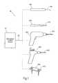
- FIG. 1is a diagrammatic view of a system usable in association with a family of different monitoring and treatment devices for use in different medical procedures.
- FIG. 2is a perspective view showing an exemplary embodiment of the system shown in FIG. 1 , the stimulation control device being removably coupled to a stimulation probe, and showing the stimulation signal path through the system.
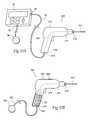
- FIG. 3Ais a side view with a portion broken away and in section showing the stimulation probe having the stimulation control device embedded within the stimulation probe.
- FIG. 3Bis a side view with a portion broken away and in section showing the stimulation probe having the stimulation control device embedded within the stimulation probe, and showing an optional needle-like return electrode.
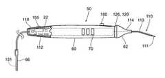
- FIG. 3Cis a side view with a portion broken away and in section showing an additional embodiment of the stimulation probe having a housing that includes a gripping base and a flexible nose cone, and an illuminating ring indicator.
- FIG. 4Ais a side view of the stimulation probe of FIG. 3 c , showing the users hand in a position on the stimulation probe to move the flexible nose cone.
- FIG. 4Bis a side view of the stimulation probe of FIG. 4A , showing the users hand flexing the flexible nose cone.
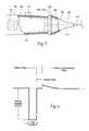
- FIG. 5is a side view with a portion broken away and in section showing elements of the flexible nose cone, the ring indicator, and the gripping base.
- FIG. 6is a graphical view of a desirable biphasic stimulus pulse output of the stimulation device.
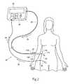
- FIG. 7is a view showing how the geometry of the stimulation control device shown in FIG. 2 aids in its positioning during a surgical procedure.
- FIG. 8is a block diagram of a circuit that the stimulation control device shown throughout the Figs. can incorporate.
- FIGS. 9A and 9Bare perspective views showing the stimulation control device in use with a cutting device.
- FIGS. 10A and 10Bare perspective views showing the stimulation control device in use with a drilling or screwing device.
- FIGS. 11A and 11Bare perspective views showing the stimulation control device in use with a pilot auger device.
- FIGS. 12A and 12Bare perspective views showing the stimulation control device in use with a fixation device.
- FIG. 13is a plane view of a kit used in conjunction with the stimulation probe shown in FIG. 3C , and including the stimulation probe and instructions for use.
- FIG. 14is a perspective view of the stimulation probe shown in FIG. 3C .
- FIG. 15is an exploded view of the stimulation probe shown in FIG. 14 .
- This Specificationdiscloses various systems and methods for safeguarding against nerve, muscle, and tendon injury during surgical procedures or confirming the identity and/or location of nerves, muscles, and tendons and evaluating their function or the function of muscles enervated by those nerves.
- the systems and methodsare particularly well suited for assisting surgeons in identification of nerves and muscles in order to assure nerve and muscle integrity during medical procedures using medical devices such as stimulation monitors, cutting, drilling, and screwing devices, pilot augers, and fixation devices. For this reason, the systems and methods will be described in the context of these medical devices.
- the systems and methodsdesirably allow the application of a stimulation signal at sufficiently high levels for the purposes of locating, stimulating, and evaluating nerve or muscle, or both nerve and muscle integrity innumerous medical procedures, including, but not limited to, evaluating proximity to a targeted tissue region, evaluating proximity to a nerve or to identify nerve tissue, evaluating if a nerve is intact (i.e., following a traumatic injury) to determine if a repair may be needed, evaluating muscle contraction to determine whether or not the muscle is innervated and/or whether the muscle is intact and/or whether the muscle is severed, and evaluating muscle and tendon length and function following a repair or tendon transfer prior to completing a surgical procedure.
- FIG. 1shows an illustrative system 20 for locating and identifying tissue and safeguarding against tissue and/or bone injury during surgical procedures.
- the system 20is configured for locating, monitoring, and stimulating tissue and other structures throughout the body.
- the system 20includes a stimulation control device 22 operating individually or in conjunction with one or more of a family of stimulating medical devices including, for example, a stimulation monitor or probe 100 , a cutting device 200 , a drilling or screwing device 300 , a pilot auger 400 , and a fixation device 500 .
- the stimulation control device 22functions in the system 20 to generate an electrical stimulation signal 29 .
- the stimulation signal 29flows from the stimulation control device 22 through a lead 24 to a medical device (e.g., stimulation probe 100 ).
- the stimulation signal 29then flows through a predefined insulated path 124 within the stimulation probe 100 and to an operative element, such as an electrically conductive surface, i.e., a coupled electrode 110 .
- the electrode 110is to be positioned on or near a region of a patient to be stimulated.
- a return electrode (or indifferent electrode) 38provides an electrical path from the body back to the control device 22 .
- the stimulation control device 22may operate in a monopolar or bipolar configuration, as will be described in greater detail later.
- the stimulation signal 29is adapted to provide an indication or status of the device.
- the indicationmay include a physical motor response (e.g., twitching), and/or one or more visual or audio signals from the stimulation control device 22 , which indicate to the surgeon the status of the device, and/or close proximity of the electrode 110 to a nerve, or a muscle, or a nerve and a muscle.
- the stimulation control devicemay also indicate to the surgeon that the stimulation control device is operating properly and delivering a stimulus current.
- the configuration of the stimulating medical devices that form a part of the systemcan vary in form and function. Various representative embodiments of illustrative medical devices will be described.
- FIGS. 3A to 3Cshow various embodiments of a hand held stimulation monitor or probe 50 for identification and testing of nerves and/or muscles during surgical procedures.
- the stimulation probe 50may accommodate within a generally tubularly housing 112 the electrical circuitry of a stimulation control device 22 .
- the stimulation probe 50is desirably an ergonomic, sterile, single use instrument intended for use during surgical procedures to identify nerves and muscles, muscle attachments, or to contract muscles to assess the quality of surgical interventions or the need for surgical interventions, or to evaluate the function of nerves already identified through visual means.
- the stimulation probe 50may be sterilized using ethylene oxide, for example.
- the stimulation probe 50is preferably sized small enough to be held and used by one hand during surgical procedures, and is ergonomically designed for use in either the left or right hand.
- the stimulation probe 50may have a width of about 20 millimeters to about 30 millimeters, and desirably about 25 millimeters.
- the length of the stimulation probe 50(not including the operative element 110 ) may be about 18 centimeters to about 22 centimeters, and desirably about 20 centimeters.
- the operative element 110may also include an angle or bend to facilitate access to deep as well as superficial structures without the need for a large incision. The operative element 110 will be described in greater detail later.
- a visual or audio indicator 126 incorporated with the housing 112provides reliable feedback to the surgeon as to the request and delivery of stimulus current.
- the stimulation probe 50includes a housing 112 that comprises a gripping base portion 60 and an operative element adjustment portion 62 .
- the operative element 110extends from the proximal end of the adjustment portion 62 .
- the adjustment portionas will be described as a nose cone 62 , may be flexible. This flexibility allows the surgeon to use either a finger or a thumb positioned on the nose cone 62 to make fine adjustments to the position of stimulating tip 111 of the operative element 110 at the targeted tissue region (see FIGS. 4A and 4B ).
- the surgeonis able to grasp the gripping base 60 with the fingers and palm of the hand, and position the thumb on the nose cone 62 , and with pressure applied with the thumb, cause the stimulating tip 111 to move while maintaining a steady position of the gripping base portion 62 .
- This flexible nose cone 62 featureallows precise control of the position of the stimulating tip 111 with only the movement of the surgeon's thumb (or finger, depending on how the stimulating probe is held).
- the flexible nose cone 62may comprise a single element or it may comprise at least an inner portion 64 and an outer portion 66 , as shown in FIG. 5 .
- the inner portion 64 of the nose cone 62may be made of a thermoplastic material having some flexibility.
- One examplemay be LUSTRAN® ABS 348, or similar material.
- the outer portion 66may comprise a softer over molded portion and may be made of a thermoplastic elastomer material having some flexibility.
- One examplemay be VERSAFLEXTM OM 3060-1 from GLS Corp.
- the nose cone 62is desirably generally tapered.
- the nose cone 62may be rounded, as shown in FIGS. 3A and 3B , or the nose cone may be more conical in shape, as shown in FIG. 3C .
- the nose cone 62may also include one or more features, such as ribs or dimples 72 , as shown in FIG. 14 , to improve the gripping, control, and stability of the stimulation probe 50 within the surgeon's hand.
- the gripping base portion 60 of the housing 112may also include an overmolded portion 68 .
- the overmolded portion 68may comprise the full length of the gripping base portion 60 , or only a portion of the gripping base 60 .
- the soft overmolded portion 68may include one or more features, such as dimples or ribs 70 , as shown, to improve the gripping, control, and stability of the stimulation probe 50 within the surgeon's hand.
- the overmolded portion 68may comprise the same or similar material as the thermoplastic elastomer material used for the outer portion 66 of the flexible nose cone 62 .
- the stimulation probe 50includes a housing 112 that carries an insulated lead 124 .
- the insulated lead 124connects the operative element 110 positioned at the housing's proximal end 114 to the circuitry 22 within the housing 112 (see FIG. 3A ). It is to be appreciated that the insulated lead is not necessary and the operative element 110 may be coupled to the circuitry 22 (see FIG. 3C ).
- the lead 124 within the housing 112is insulated from the housing 112 using common insulating means (e.g., wire insulation, washers, gaskets, spacers, bushings, and the like).
- the conductive tip 111 of the operative element 110is positioned in electrical conductive contact with at least one muscle, or at least one nerve, or at least one muscle and nerve.
- the stimulation probe 50is mono-polar and is equipped with a single operative element (i.e., electrode) 110 at the housing proximal end 114 .
- a return electrode 130 , 131may be coupled to the stimulation probe 50 and may be any of a variety of electrode types (e.g., paddle, needle, wire, or surface), depending on the surgical procedure being performed.
- the various return electrodes 130 , 131are coupled to the housing distal end 118 .
- the stimulation device 50itself may be bipolar by including a return electrode in the operative element 110 , which precludes the use of a return electrode coupled to the stimulation probe 50 .
- the stimulation probe 50may accommodate within the housing 112 the electrical circuitry of a stimulation control device 22 .
- the stimulation probe 50may have one or more user operable controls. Two are shown— 155 and 160 .
- Power switch 155serves a dual purpose of turning the stimulation probe 500 N and OFF (or standby), and also can be stepped to control the stimulation signal amplitude selection within a predefined range (e.g., 0.5, 2.0, and 20 mA). In this configuration, the switch may be a four position switch. Before the first use of the stimulation probe 50 , the power switch 155 is in the OFF position and keeps the stimulation probe off.
- the OFF positionnow corresponds to a standby condition, where no stimulation would be delivered.
- the stimulation probe 50once the stimulation probe 50 has been turned on, it cannot be turned off, it can only be returned to the standby condition and will remain operational for a predetermined time, e.g., at least about seven hours. This feature is intended to allow the stimulation probe 50 to only be a single use device, so it can not be turned OFF and then used again at a later date.
- the pulse control device 160allows for adjustment of the stimulation signal pulse width from a predefined range (e.g., about zero to about 200 microseconds).
- the pulse control 160may be a potentiometer to allow a slide control to increase or decrease the stimulation signal pulse width within the predefined range.
- the stimulation pulsemay have a non-adjustable frequency in the range of about 10 Hz to about 20 Hz, and desirably about 16 Hz.
- the stimulation pulsedesirably has a biphasic waveform with controlled current during the cathodic (leading) phase, and net DC current less than 10 microamps, switch adjustable from about 0.5 milliamps to about 20 milliamps, and pulse durations adjustable from about zero microseconds up to about 200 microseconds.
- a typical, biphasic stimulus pulseis shown in FIG. 6 .
- the operative element 110exits the housing 112 at the proximal end 114 to deliver stimulus current to the excitable tissue.
- the operative element 110comprises a length and a diameter of a conductive material, and is desirably fully insulated with the exception of the most proximal end, e.g. about 1.0 millimeters to about 10 millimeters, and desirably about 4 millimeters to about 6 millimeters, which is non-insulated and serves as the stimulating tip or surface (or also referred to as active electrode) 111 to allow the surgeon to deliver the stimulus current only to the intended tissue.
- the small area of the stimulating surface 111 (the active electrode) of the operative element 110ensures a high current density that will stimulate nearby excitable tissue.
- the insulation material 113may comprise a medical grade heat shrink.
- the conductive material of the operative element 110comprises a diameter having a range between about 0.5 millimeters to about 1.5 millimeters, and may be desirably about 1.0 millimeters.
- the length of the operative element 110may be about 50 millimeters to about 60 millimeters, although it is to be appreciated that the length may vary depending on the particular application.
- the operative element 110may include one or more bends to facilitate accurate placement of the stimulating surface 111 .
- the conductive material of operative element 110is made of a stainless steel 304 solid wire, although other known conductive materials may be used.
- a return electrode 130 or 131provides an electrical path from the body back to the control device 22 within the housing 112 .
- the return electrode 130(see FIG. 3A ) may be placed on the surface of intact skin (e.g., surface electrodes as used for ECG monitoring during surgical procedures) or it might be needle-like 131 (see FIGS. 3B and 3C ), and be placed in the surgical field or penetrate through intact skin.
- the housing's distal end 118can incorporate a connector or jack 120 which provides options for return current pathways, such as through a surface electrode 130 or a needle electrode 131 , having an associated plug 122 .
- a return electrode and associated leadmay be an integral part of the stimulation probe 50 , i.e., no plug or connector, as shown in FIG. 3C .
- the device 50may desirably incorporate a visual or audio indicator 126 for the surgeon.
- This visual or audio indicator 126allows the surgeon to confirm that the stimulator 50 is delivering stimulus current to the tissue it is contacting.
- the indicator 126(which can take the form, e.g., of a light emitting diode (LED)) allows the surgeon to confirm that the stimulating tip 111 is in place, the instrument is turned ON, and that stimulus current is flowing.
- LEDlight emitting diode
- the indicator 126may be configured to illuminate continuously in one color when the stimulation probe 50 is turned on but not in contact with tissue. After contact with tissue is made, the indicator 126 may flash (i.e., blink) to indicate that stimulation is being delivered. If the stimulation has been requested, i.e., the stimulation probe has been turned on, but there is no stimulation being delivered because of a lack of continuity between the operative element 110 and the return electrode 130 , or an inadequate connection of the operative element 110 or the return electrode 130 to the patient tissue, the indicator 126 may illuminate in a different color, and may illuminate continuously or may flash.
- the indicator 126comprises a ring indicator 128 that provides a visual indication around at least a portion, and desirably all of the circumference of the stimulation probe 50 generally near the flexible nose cone 62 .
- the visual ring indicator 128may be an element of the gripping portion 60 , or it may be an element of the flexible nose cone 62 , or the ring indicator may positioned between the gripping portion 60 and the flexible nose cone 62 .
- the ring indicator 128may also include a reflective element 129 to improve and focus the illumination effect of the light emitting source, e.g., one or more LEDs.
- the ring indicator 128 and the reflective elementmay be a single component, or more than one component (as can be seen in FIGS. 5 and 15 ).
- Audio feedbackalso makes possible the feature of assisting the surgeon with monitoring nerve integrity during surgery.
- the insulated lead 124connects to the operative element 110 that, in use, is positioned within the surgical field on a nerve distal to the surgical site. Stimulation of the nerve causes muscle contraction distally.
- the stimulation control device 22 incorporated within the housing 112may be programmed to provide an audio tone followed by a stimulation pulse at prescribed intervals. The audio tone reminds the surgeon to observe the distal muscle contraction to confirm upon stimulation that the nerve is functioning and intact.
- FIG. 15shows an exploded view of a representative stimulation probe 50 .
- the stimulation control device 22is positioned within the housing 112 .
- a battery 34is electrically coupled to the control device 22 .
- a first housing element 90 and a second housing element 92partially encapsulate the control device 22 .
- the ring indicator 128 and the reflective element 129are coupled to the proximal end of the housing 112 .
- the operative element 110extends through the nose cone 62 and couples to the control device 22 .
- the stimulation probe 50will be constructed in a manner to conform to at least the IPX1 standard for water ingress.
- the stimulation control device 22may be housed in a separate case, with its own input/output (I/O) controls 26 .
- the stimulation control device 22is sized small enough to be easily removably fastened to a surgeon's arm or wrist during the surgical procedure, or otherwise positioned in close proximity to the surgical location (as shown in FIG. 7 ), to provide sufficient audio and/or visual feedback to the surgeon.
- the separate stimulation control device 22can be temporarily coupled by a lead to a family of various medical devices for use.
- the present inventionincludes a method of identifying/locating tissue, e.g., a nerve or muscle, in a patient that comprises the steps of providing a hand-held stimulation probe 50 , 100 as set forth above, engaging a patient with the first operative element 110 and the second electrode 130 , moving the power switch 155 to an activation position causing a stimulation signal 29 to be generated by the stimulation control device 22 and transmitted to the first operative element 110 , through the patient's body to the second electrode 130 , and back to the stimulation control device 22 .
- the methodmay also include the step of observing the indicator 126 to confirm the stimulation probe 50 , 100 is generating a stimulation signal.
- the methodmay also include the step of observing a tissue region to observe tissue movement or a lack thereof.
- the stimulation control device 22includes a circuit 32 that generates electrical stimulation waveforms.
- a battery 34desirably provides the power.
- the control device 22also desirably includes an on-board, programmable microprocessor 36 , which carries embedded code. The code expresses pre-programmed rules or algorithms for generating the desired electrical stimulation waveforms using the stimulus output circuit 46 and for operating the visible or audible indicator 126 based on the controls actuated by the surgeon.
- the size and configuration of the stimulation control device 22makes for an inexpensive device, which is without manual internal circuit adjustments. It is likely that the stimulation control device 22 of this type will be fabricated using automated circuit board assembly equipment and methods.
- a stimulation control device 22 as just describedmay be electrically coupled through a lead, or embedded within various devices commonly used in surgical procedures (as previously described for the stimulation probe 50 ).
- FIGS. 9A and 9Ba device 200 is shown that incorporates all the features disclosed in the description of the stimulation probe 50 , 100 , except the device 200 comprises the additional feature of providing an “energized” surgical device or tool.
- FIG. 9Ashows the tool to be a cutting device 200 (e.g., scalpel) removably coupled to a stimulation control device 22 .
- a cutting device 200e.g., scalpel
- the cutting device 200includes a body 212 that carries an insulated lead 224 .
- the insulated lead 224connects to an operative element, such as electrode 210 , positioned at the body proximal end 214 and a plug-in receptacle 219 at the body distal end 118 .
- the lead 224 within the body 212is insulated from the body 212 using common insulating means (e.g., wire insulation, washers, gaskets, spacers, bushings, and the like).
- the electrode 210performs the cutting feature (e.g., knife or razor).
- the electrode 210performs the cutting feature in electrical conductive contact with at least one muscle, or at least one nerve, or at least one muscle and nerve.
- the cutting device 200desirably includes a plug-in receptacle 216 for the electrode 210 , allowing for use of a variety of cutting electrode shapes and types (e.g., knife, razor, pointed, blunt, curved), depending on the specific surgical procedure being performed.
- the lead 224electrically connects the electrode 210 to the stimulation control device 22 through plug-in receptacle 219 and lead 24 .
- the cutting device 200is mono-polar and is equipped with a single electrode 210 at the body proximal end 214 .
- the stimulation control device 22includes a return electrode 38 which functions as a return path for the stimulation signal.
- Electrode 38may be any of a variety of electrode types (e.g., paddle, needle, wire, or surface), depending on the surgical procedure being performed.
- the return electrode 38may be attached to the stimulation device 22 by way of a connector or plug-in receptacle 39 .
- the cutting device 200may be bipolar, which precludes the use of the return electrode 38 .
- the cutting device 200accommodates within the body 212 the electrical circuitry of the stimulation control device 22 .
- the cutting device 200may have at least two operational slide controls, 255 and 260 .
- Power switch 255serves a dual purpose of turning the stimulation signal to the cutting device 200 on and off, and also is stepped to control the stimulation signal amplitude selection from a predefined range (e.g., 0.5, 2.0, and 20 mA).
- the pulse control switch 260allows for adjustment of the stimulation signal pulse width from a predefined range (e.g., zero through 200 microseconds).
- a second plug-in receptacle 220may be positioned for receipt of a second lead 222 .
- Lead 222connects to electrode 230 which functions as a return path for the stimulation signal when the cutting device 200 is operated in a mono-polar mode.
- the device 200may incorporate a visual or audio indicator for the surgeon, as previously described.
- the present inventionincludes a method of identifying/locating tissue, e.g., a nerve or muscle, in a patient that comprises the steps of providing cutting device 200 as set forth above, engaging a patient with the first electrode 210 and the second electrode 230 , moving the power switch 255 to an activation position causing a stimulation signal 29 to be generated by the stimulation control device 22 and transmitted to the first electrode 210 , through the patient's body to the second electrode 230 , and back to the stimulation control device 22 .
- the methodmay also include the step of observing the indicator 126 to confirm the cutting device 200 is generating a stimulation signal.
- the methodmay also include the step of observing a tissue region to observe tissue movement or a lack thereof.
- a device 300is shown that incorporates all the features disclosed in the description of the stimulation probe 50 , 100 , except the device 300 comprises the additional feature of providing an “energized” surgical device or tool, which comprises a drilling device 300 .
- drilling device 300is removably coupled to a stimulation control device 22 .
- the drilling device 300includes a body 312 that carries an insulated lead 324 .
- the insulated lead 324connects to an operative element, such as electrode 310 , positioned at the body proximal end 314 and a plug-in receptacle 319 at the body distal end 318 .
- the lead 324 within the body 312is insulated from the body 312 using common insulating means (e.g., wire insulation, washers, gaskets, spacers, bushings, and the like).
- the electrode 310performs the drilling feature.
- the electrode 310may also perform a screwing feature as well.
- the electrode 310performs the drilling feature in electrical conductive contact with a hard structure (e.g., bone).
- the drilling device 300desirably includes a plug-in receptacle or chuck 316 for the electrode 310 , allowing for use of a variety of drilling and screwing electrode shapes and sizes (e.g., 1 ⁇ 4 and 3 ⁇ 8 inch drill bits, Phillips and flat slot screw drivers), depending on the specific surgical procedure being performed.
- the lead 324electrically connects the electrode 310 to the stimulation control device 22 through plug-in receptacle 319 and lead 324 .
- the drilling device 300is mono-polar and is equipped with a single electrode 310 at the body proximal end 314 .
- the stimulation control device 22includes a return electrode 38 which functions as a return path for the stimulation signal.
- Electrode 38may be any of a variety of electrode types (e.g., paddle, needle, wire, or surface), depending on the surgical procedure being performed.
- the return electrode 38may be attached to the stimulation device 22 by way of a connector or plug-in receptacle 39 .
- the drilling device 300may be bipolar, which precludes the use of the return electrode 38 .
- the drilling device 300is shown to accommodate within the body 312 the electrical circuitry of the stimulation control device 22 .
- the drilling device 300may have at least two operational slide controls, 355 and 360 .
- Power switch 355serves a dual purpose of turning the stimulation signal to the drilling device 300 on and off, and also is also stepped to control the stimulation signal amplitude selection from a predefined range (e.g., 0.5, 2.0, and 20 mA).
- the pulse control switch 360allows for adjustment of the stimulation signal pulse width from a predefined range (e.g., zero through 200 microseconds).
- a second plug-in receptacle 320may be positioned for receipt of a second lead 322 .
- Lead 322connects to electrode 330 which functions as a return path for the stimulation signal when the drilling device 300 is operated in a mono-polar mode.
- the device 300may incorporate a visual or audio indicator for the surgeon, as previously described.
- the present inventionincludes a method of identifying/locating tissue, e.g., a nerve or muscle, in a patient that comprises the steps of providing a drilling device 300 as set forth above, engaging a patient with the first electrode 310 and the second electrode 330 , moving the power switch 355 to an activation position causing a stimulation signal 29 to be generated by the stimulation control device 22 and transmitted to the first electrode 310 , through the patient's body to the second electrode 330 , and back to the stimulation control device 22 .
- the methodmay also include the step of observing the indicator 126 to confirm the drilling device 400 is generating a stimulation signal.
- the methodmay also include the step of observing a tissue region to observe tissue movement or a lack thereof.
- An additional aspect of the inventionprovides systems and methods for controlling operation of a family of stimulating devices comprising a stimulation control device electrically coupled to a pilot auger for hard surface rotary probing.
- FIG. 11Ashows a pilot auger device 400 removably coupled to a stimulation control device 22 .
- the pilot auger device 400includes a body 412 that carries an insulated lead 424 .
- the insulated lead 424connects to an operative element, such as an electrode 410 , positioned at the body proximal end 414 and a plug-in receptacle 419 at the body distal end 418 .
- the lead 424 within the body 412is insulated from the body 412 using common insulating means (e.g., wire insulation, washers, gaskets, spacers, bushings, and the like).
- the electrode 410performs the pilot augering feature.
- the electrode 410performs the pilot augering feature in electrical conductive contact with a hard structure (e.g., bone).
- the pilot auger device 400desirably includes a plug-in receptacle or chuck 416 for the electrode 410 , allowing for use of a variety of pilot augering electrode shapes and sizes (e.g., 1/32, 1/16, and 1 ⁇ 8 inch), depending on the specific surgical procedure being performed.
- the lead 24electrically connects the electrode 410 to the stimulation control device 22 through plug-in receptacle 419 and lead 24 .
- the pilot auger device 400is mono-polar and is equipped with a single electrode 410 at the body proximal end 414 .
- the stimulation control device 22includes a return electrode 38 which functions as a return path for the stimulation signal.
- Electrode 38may be any of a variety of electrode types (e.g., paddle, needle, wire, or surface), depending on the surgical procedure being performed.
- the return electrode 38may be attached to the stimulation device 22 by way of a connector or plug-in receptacle 39 .
- the pilot auger device 400may be bipolar, which precludes the use of the return electrode 38 .
- the pilot auger device 400may accommodate within the body 412 the electrical circuitry of the stimulation control device 22 .
- a second plug-in receptacle 420may be positioned for receipt of a second lead 422 .
- Lead 422connects to electrode 430 which functions as a return path for the stimulation signal when the pilot auger device 400 is operated in a mono-polar mode.
- the pilot auger device 400includes a power switch 455 . When moved to an activation position, a stimulation signal is generated by the stimulation control device 22 . Additionally, the device 400 may incorporate a visual or audio indicator for the surgeon, as previously described.
- the present inventionincludes a method of identifying/locating tissue, e.g., a nerve or muscle, in a patient that comprises the steps of providing a pilot auger device 400 as set forth above, engaging a patient with the first electrode 410 and the second electrode 430 , moving the power switch 455 to an activation position causing a stimulation signal to be generated by the stimulation control device 22 and transmitted to the first electrode 410 , through the patient's body to the second electrode 430 , and back to the stimulation control device 22 .
- the methodmay also include the step of observing the indicator 126 to confirm the pilot auger device 400 is generating a stimulation signal.
- the methodmay also include the step of observing a tissue region to observe tissue movement or a lack thereof.
- An additional aspect of the inventionprovides systems and methods for controlling operation of a family of stimulating devices comprising a stimulation control device electrically coupled to a fixation device or a wrench or screwdriver for placing the fixation device.
- a fixation devicee.g., orthopedic hardware, pedicle screws
- fusionspinal stabilization procedures
- internal bone fixation procedurese.g., internal bone fixation procedures.
- FIG. 12Ashows a fixation device 500 removably coupled to a stimulation control device 22 .
- the fixation device 500includes a rectangularly shaped body 512 that also serves as an operative element, such as electrode 510 .
- the fixation device 500may take on an unlimited number of shapes as necessary for the particular procedure taking place.
- Pedicle screws 535may be used to secure the fixation device to the bony structure.
- the electrode 510performs the fixation feature in electrical conductive contact with a hard structure (e.g., bone).
- the fixation device 500 or wrench or screwdriver for placing the fixation devicedesirably includes a plug-in receptacle 519 .
- the fixation device 500may take on an unlimited variety of shapes and sizes depending on the specific surgical procedure being performed.
- the lead 24electrically connects the electrode 510 to the stimulation control device 22 through plug-in receptacle 519 .
- the fixation device 500is mono-polar and is equipped with the single electrode 510 .
- the stimulation control device 22includes a return electrode 38 which functions as a return path for the stimulation signal.
- Electrode 38may be any of a variety of electrode types (e.g., paddle, needle, wire, or surface), depending on the surgical procedure being performed.
- the return electrode 38may be attached to the stimulation device 22 by way of a connector or plug-in receptacle 39 .
- the fixation device 500may be bipolar, which precludes the use of the return electrode 38 .
- the fixation devicemay be a pedicle screw 535 .
- the pedicle screw 535is removably coupled to a stimulation control device 22 .
- the pedicle screw 535includes a head 570 and a shaft 572 , which both serve as an operative element, such as electrode 574 .
- the electrode 574performs the fixation feature in electrical conductive contact with a hard structure (e.g., bone), as the pedicle screw 535 is being positioned within a bony structure.
- the lead 24electrically connects the electrode 574 to the stimulation control device 22 , through a break-away connection or other similar electrical connective means.
- the fixation device 535may take on an unlimited variety of shapes and sizes depending on the specific surgical procedure being performed.
- the stimulation control device 22includes a return electrode 38 which functions as a return path for the stimulation signal.
- Electrode 38may be any of a variety of electrode types (e.g., paddle, needle, wire, or surface), depending on the surgical procedure being performed.
- the fixation device 500may be bipolar, which precludes the use of the return electrode 38 .
- the present inventionincludes a method of identifying/locating tissue, e.g., a nerve or muscle, in a patient that comprises the steps of providing a fixation device 500 as set forth above, engaging a patient with the first electrode 510 and the second electrode 38 , turning power on to the stimulation control device 22 through the I/O controls 26 , causing a stimulation signal 29 to be generated by the stimulation control device 22 and transmitted to the first electrode 510 , through the patient's body to the second electrode 38 , and back to the stimulation control device 22 .
- the methodmay also include the step of observing the indicator 126 to confirm the fixation device 500 is generating a stimulation signal.
- the methodmay also include the step of observing a tissue region to observe tissue movement or a lack thereof.
- the stimulation control device 22can incorporate various technical features to enhance its universality.
- the stimulation control device 22can be sized small enough to be held and used by one hand during surgical procedures, or to be installed within a stimulation probe or surgical device.
- the angle of the stimulating tipfacilitates access to deep as well as superficial structures without the need for a large incision.
- Visual and/or audible indication incorporated in the housingprovides reliable feedback or status to the surgeon as to the request and delivery of stimulus current.
- the stimulation control device 22may also be sized small enough to be easily removably fastened to a surgeon's arm or wrist during the surgical procedure, or positioned in close proximity to the surgical location (as shown in FIG. 7 ), to provide sufficient audio and/or visual feedback to the surgeon.
- a representative battery 34may include a size “N” alkaline battery. In one embodiment, two size “N” alkaline batteries in series are included to provide a 3 volt power source. This configuration is sized and configured to provide an operating life of at least seven hours of operation—either continuous or intermittent stimulation.
- the stimulation control device 22desirably uses a standard, commercially available micro-power, flash programmable microcontroller 36 .
- the microcontroller 36reads the controls operated by the surgeon, controls the timing of the stimulus pulses, and controls the feedback to the user about the status of the instrument (e.g., an LED with 1, 2, or more colors that can be on, off, or flashing).
- the microcontrolleroperates at a low voltage and low power.
- the microcontrollersend low voltage pulses to the stimulus output stage 46 that converts these low voltage signals into the higher voltage, controlled voltage, or controlled current, stimulus pulses that are applied to the electrode circuit.
- This stimulus output stage 46usually involves the use of a series capacitor to prevent the presence of DC current flow in the electrode circuit in normal operation or in the event of an electronic component failure.
- the stimulation probe 50 , 100make possible the application of a stimulation signal at sufficiently high levels for the purposes of locating, stimulating, and evaluating nerve or muscle, or both nerve and muscle integrity in numerous medical procedures, including, but not limited to, evaluating proximity to a targeted tissue region, evaluating proximity to a nerve or to identify nerve tissue, evaluating if a nerve is intact (i.e., following a traumatic injury) to determine if a repair may be needed, evaluating muscle contraction to determine whether or not the muscle is innervated and/or whether the muscle is intact and/or whether the muscle is severed, and evaluating muscle and tendon length and function following a repair or tendon transfer prior to completing a surgical procedure.
- kit 82Instructions for use 80 are desirably included in a kit 82 along with a stimulation probe 50 .
- the kit 82can take various forms.
- kit 82comprises a sterile, wrapped assembly.
- a representative kit 82includes an interior tray 84 made, e.g., from die cut cardboard, plastic sheet, or thermo-formed plastic material, which hold the contents.
- Kit 82also desirably includes instructions for use 80 for using the contents of the kit to carry out a desired therapeutic and/or diagnostic objectives.
- the instructions 80guide the user through the steps of unpacking the stimulation probe 50 , positioning the electrodes, and disposing of the single use disposable stimulator 50 .
- Representative instructionsmay include, but are not limited to:
Landscapes
- Health & Medical Sciences (AREA)
- Life Sciences & Earth Sciences (AREA)
- Surgery (AREA)
- Animal Behavior & Ethology (AREA)
- Public Health (AREA)
- Veterinary Medicine (AREA)
- General Health & Medical Sciences (AREA)
- Engineering & Computer Science (AREA)
- Biomedical Technology (AREA)
- Heart & Thoracic Surgery (AREA)
- Medical Informatics (AREA)
- Molecular Biology (AREA)
- Orthopedic Medicine & Surgery (AREA)
- Biophysics (AREA)
- Physics & Mathematics (AREA)
- Pathology (AREA)
- Neurology (AREA)
- Nuclear Medicine, Radiotherapy & Molecular Imaging (AREA)
- Oral & Maxillofacial Surgery (AREA)
- Dentistry (AREA)
- Rheumatology (AREA)
- Neurosurgery (AREA)
- Physiology (AREA)
- Electrotherapy Devices (AREA)
- Surgical Instruments (AREA)
Abstract
Description
- Remove the
stimulation probe 50 fromsterile package 88. - Remove cover94 (e.g., a silicone cover) from the
operative element 110. - Remove
protective cover 86 from thereturn electrode 131. - Position the
return electrode 131 in contact with the patient such that:- 1. The return electrode is desirably positioned in an area remote from the area to be stimulated.
- 2. The return electrode is desirably not positioned across the body from the side being stimulated.
- 3. The return electrode is desirably not in muscle tissue.
- Turn the
stimulation probe 50 ON by moving thepower switch 155 from OFF to the 0.5 mA setting (or greater). Thestimulation probe 50 desirably is turned ON before theoperative element 110 makes contact with tissue. - The
indicator 126 will be illuminated yellow (for example) continuously if thestimulation probe 50 is ON, but not in contact with tissue. - Contact tissue with the
operative element 110. - Adjust the
pulse control 160 gradually to increase the level of stimulation. Theindicator 126 will flash yellow indicating that stimulation is being delivered. - A flashing red (for example)
indicator 126 means that stimulation has been requested, but no stimulation is being delivered because of inadequate connection of theoperative element 110 or thereturn electrode 131 to the patient tissue. Check the return electrode contact and position, and check theoperative element 110 contact and position. - Placing the
power switch 155 to the off/standby position will stop stimulation and thevisual indictor 126 will be illuminated yellow continuously. - Placing the
pulse control 160 at the minimum position will stop stimulation and thevisual indictor 126 will be illuminated yellow continuously. - A low/
depleted battery 34 will cause thestimulation probe 50 to automatically turn OFF and thevisual indicator 126 will not be illuminated. No further use of thestimulator 50 will be possible. - At end of use, move the
power switch 155 to the off/standby position and move thepulse control 160 to the minimum position. - Cut off and dispose of the
return electrode 131 in an appropriate sharps/biohazard container. - Dispose of the
stimulation probe 50 per hospital or facility guidelines.
- Remove the
Claims (12)
Priority Applications (19)
| Application Number | Priority Date | Filing Date | Title |
|---|---|---|---|
| US11/651,165US7878981B2 (en) | 2005-03-01 | 2007-01-09 | Systems and methods for intra-operative stimulation |
| CN200880001960.2ACN101594906B (en) | 2007-01-09 | 2008-01-08 | Systems and methods intra-operative stimulation |
| JP2009544953AJP5410297B2 (en) | 2007-01-09 | 2008-01-08 | Intraoperative stimulation system |
| CA002674446ACA2674446A1 (en) | 2007-01-09 | 2008-01-08 | Systems and methods for intra-operative stimulation |
| PCT/US2008/000251WO2008085965A2 (en) | 2007-01-09 | 2008-01-08 | Systems and methods intra-operative stimulation |
| AU2008205293AAU2008205293B2 (en) | 2007-01-09 | 2008-01-08 | Systems and methods intra-operative stimulation |
| EP08705519.0AEP2106273A4 (en) | 2007-01-09 | 2008-01-08 | SYSTEMS AND METHODS FOR OPERATIVE STIMULATION |
| US12/806,705US20110054346A1 (en) | 2005-03-01 | 2010-08-19 | Systems and methods for Intra-operative semi-quantitative threshold neural response testing related applications |
| US12/806,698US20110060243A1 (en) | 2005-03-01 | 2010-08-19 | Systems and methods for intra-operative regional neural stimulation |
| US12/806,697US20110060242A1 (en) | 2005-03-01 | 2010-08-19 | Systems and methods for intra-operative stimulation within a surgical field |
| US12/806,691US20110060238A1 (en) | 2005-03-01 | 2010-08-19 | Systems and methods for intra-operative physiological functional stimulation |
| US13/014,452US8172768B2 (en) | 2005-03-01 | 2011-01-26 | Systems and methods for intra-operative stimulation |
| US13/466,485US8500652B2 (en) | 2005-03-01 | 2012-05-08 | System for intra-operative stimulation including visual indication of absence of delivery of stimulation signal |
| US13/475,289US20120296442A1 (en) | 2005-03-01 | 2012-05-18 | Systems and methods for intra-operative physiological functional stimulation |
| US13/934,384US10470678B2 (en) | 2005-03-01 | 2013-07-03 | Systems and methods for intra-operative stimulation |
| US14/019,170US10154792B2 (en) | 2005-03-01 | 2013-09-05 | Stimulation device adapter |
| US14/473,221US20140371622A1 (en) | 2005-03-01 | 2014-08-29 | Systems and methods for intra-operative regional neural stimulation |
| US16/221,692US11576599B2 (en) | 2005-03-01 | 2018-12-17 | Stimulation device adapter |
| US16/679,828US20200069202A1 (en) | 2005-03-01 | 2019-11-11 | Systems and methods for intra-operative stimulation |
Applications Claiming Priority (3)
| Application Number | Priority Date | Filing Date | Title |
|---|---|---|---|
| US65727705P | 2005-03-01 | 2005-03-01 | |
| US11/099,848US7896815B2 (en) | 2005-03-01 | 2005-04-06 | Systems and methods for intra-operative stimulation |
| US11/651,165US7878981B2 (en) | 2005-03-01 | 2007-01-09 | Systems and methods for intra-operative stimulation |
Related Parent Applications (2)
| Application Number | Title | Priority Date | Filing Date |
|---|---|---|---|
| US11/099,848Continuation-In-PartUS7896815B2 (en) | 2005-03-01 | 2005-04-06 | Systems and methods for intra-operative stimulation |
| US14/019,170Continuation-In-PartUS10154792B2 (en) | 2005-03-01 | 2013-09-05 | Stimulation device adapter |
Related Child Applications (5)
| Application Number | Title | Priority Date | Filing Date |
|---|---|---|---|
| US12/806,697Continuation-In-PartUS20110060242A1 (en) | 2005-03-01 | 2010-08-19 | Systems and methods for intra-operative stimulation within a surgical field |
| US12/806,691Continuation-In-PartUS20110060238A1 (en) | 2005-03-01 | 2010-08-19 | Systems and methods for intra-operative physiological functional stimulation |
| US12/806,705Continuation-In-PartUS20110054346A1 (en) | 2005-03-01 | 2010-08-19 | Systems and methods for Intra-operative semi-quantitative threshold neural response testing related applications |
| US12/806,698Continuation-In-PartUS20110060243A1 (en) | 2005-03-01 | 2010-08-19 | Systems and methods for intra-operative regional neural stimulation |
| US13/014,452ContinuationUS8172768B2 (en) | 2005-03-01 | 2011-01-26 | Systems and methods for intra-operative stimulation |
Publications (2)
| Publication Number | Publication Date |
|---|---|
| US20070191915A1 US20070191915A1 (en) | 2007-08-16 |
| US7878981B2true US7878981B2 (en) | 2011-02-01 |
Family
ID=39615790
Family Applications (5)
| Application Number | Title | Priority Date | Filing Date |
|---|---|---|---|
| US11/651,165Expired - LifetimeUS7878981B2 (en) | 2005-03-01 | 2007-01-09 | Systems and methods for intra-operative stimulation |
| US13/014,452Expired - LifetimeUS8172768B2 (en) | 2005-03-01 | 2011-01-26 | Systems and methods for intra-operative stimulation |
| US13/466,485Expired - LifetimeUS8500652B2 (en) | 2005-03-01 | 2012-05-08 | System for intra-operative stimulation including visual indication of absence of delivery of stimulation signal |
| US13/934,384Expired - LifetimeUS10470678B2 (en) | 2005-03-01 | 2013-07-03 | Systems and methods for intra-operative stimulation |
| US16/679,828AbandonedUS20200069202A1 (en) | 2005-03-01 | 2019-11-11 | Systems and methods for intra-operative stimulation |
Family Applications After (4)
| Application Number | Title | Priority Date | Filing Date |
|---|---|---|---|
| US13/014,452Expired - LifetimeUS8172768B2 (en) | 2005-03-01 | 2011-01-26 | Systems and methods for intra-operative stimulation |
| US13/466,485Expired - LifetimeUS8500652B2 (en) | 2005-03-01 | 2012-05-08 | System for intra-operative stimulation including visual indication of absence of delivery of stimulation signal |
| US13/934,384Expired - LifetimeUS10470678B2 (en) | 2005-03-01 | 2013-07-03 | Systems and methods for intra-operative stimulation |
| US16/679,828AbandonedUS20200069202A1 (en) | 2005-03-01 | 2019-11-11 | Systems and methods for intra-operative stimulation |
Country Status (7)
| Country | Link |
|---|---|
| US (5) | US7878981B2 (en) |
| EP (1) | EP2106273A4 (en) |
| JP (1) | JP5410297B2 (en) |
| CN (1) | CN101594906B (en) |
| AU (1) | AU2008205293B2 (en) |
| CA (1) | CA2674446A1 (en) |
| WO (1) | WO2008085965A2 (en) |
Cited By (46)
| Publication number | Priority date | Publication date | Assignee | Title |
|---|---|---|---|---|
| US20090054804A1 (en)* | 2007-04-03 | 2009-02-26 | Nuvasive Inc. | Neurophysiologic monitoring system |
| US20100069940A1 (en)* | 2008-09-12 | 2010-03-18 | Miller Matthew C | Ultrasonic Device for Fingertip Control |
| US20110060238A1 (en)* | 2005-03-01 | 2011-03-10 | Checkpoint Surgical, Llc | Systems and methods for intra-operative physiological functional stimulation |
| US20110092916A1 (en)* | 2008-12-02 | 2011-04-21 | Allergan, Inc. | Injection device |
| US20110112530A1 (en)* | 2009-11-06 | 2011-05-12 | Keller Craig A | Battery Powered Electrosurgery |
| US20110137286A1 (en)* | 2008-05-30 | 2011-06-09 | Allergan, Inc. | Injection device for soft-tissue augmentation fillers, bioactive agents and other biocompatible materials in liquid or gel form |
| US20120238902A1 (en)* | 2005-03-01 | 2012-09-20 | Checkpoint Surgical, Llc | Systems and methods for intra-operative stimulation |
| US20130131633A1 (en)* | 2011-11-18 | 2013-05-23 | Allergan, Inc. | Modular injection system and method for diluting an injectable fluid |
| US8603028B2 (en) | 2011-11-18 | 2013-12-10 | Allergan, Inc. | Injection device having an angled tip portion |
| US8641210B2 (en) | 2011-11-30 | 2014-02-04 | Izi Medical Products | Retro-reflective marker including colored mounting portion |
| US8661573B2 (en) | 2012-02-29 | 2014-03-04 | Izi Medical Products | Protective cover for medical device having adhesive mechanism |
| US20140073985A1 (en)* | 2005-03-01 | 2014-03-13 | Checkpoint Surgical, Llc | Stimulation device adapter |
| US8888751B2 (en) | 2009-12-07 | 2014-11-18 | Allergan, Inc. | Slotted syringe |
| US20150005648A1 (en)* | 2013-07-01 | 2015-01-01 | Zurich Medical Inc | Apparatus and method for intravascular measurements |
| US8992481B2 (en) | 2010-05-19 | 2015-03-31 | Allergan, Inc. | Modular injection device |
| US9095654B2 (en) | 2012-08-14 | 2015-08-04 | Allergan, Inc. | Syringe for mixing and dispensing adipose tissue |
| US9107688B2 (en) | 2008-09-12 | 2015-08-18 | Ethicon Endo-Surgery, Inc. | Activation feature for surgical instrument with pencil grip |
| US9392953B1 (en) | 2010-09-17 | 2016-07-19 | Nuvasive, Inc. | Neurophysiologic monitoring |
| US9757072B1 (en) | 2013-02-11 | 2017-09-12 | Nuvasive, Inc. | Waveform marker placement algorithm for use in neurophysiologic monitoring |
| US9757067B1 (en) | 2012-11-09 | 2017-09-12 | Nuvasive, Inc. | Systems and methods for performing neurophysiologic monitoring during spine surgery |
| US20180147410A1 (en)* | 2016-11-26 | 2018-05-31 | Xialing Zhang | Adjustable angle neuro stimulation probe apapratus |
| US10132607B2 (en) | 2016-11-03 | 2018-11-20 | Edge Surgical, Inc. | Surgical depth instrument having neuromonitoring capabilities |
| US10265477B2 (en) | 2013-05-23 | 2019-04-23 | Allergan, Inc. | Mechanical syringe accessory |
| US20190133609A1 (en)* | 2016-05-03 | 2019-05-09 | Bien-Air Holding Sa | Integrated intraoperative nerve monitoring system |
| US10420480B1 (en) | 2014-09-16 | 2019-09-24 | Nuvasive, Inc. | Systems and methods for performing neurophysiologic monitoring |
| US10433928B2 (en) | 2015-03-10 | 2019-10-08 | Allergan Pharmaceuticals Holdings (Ireland) Unlimited Company | Multiple needle injector |
| USD865950S1 (en) | 2017-03-24 | 2019-11-05 | Allergan, Inc. | Syringe device |
| US10589089B2 (en) | 2017-10-25 | 2020-03-17 | Epineuron Technologies Inc. | Systems and methods for delivering neuroregenerative therapy |
| US10596321B2 (en) | 2016-04-08 | 2020-03-24 | Allergan, Inc. | Aspiration and injection device |
| US10792427B2 (en) | 2014-05-13 | 2020-10-06 | Allergan, Inc. | High force injection devices |
| US10792080B2 (en) | 2017-06-14 | 2020-10-06 | Edge Surgical, Inc. | Devices for minimally invasive procedures |
| US10912483B2 (en) | 2018-03-05 | 2021-02-09 | Edge Surgical, Inc. | Handheld devices for use in medical procedures |
| US11026627B2 (en) | 2013-03-15 | 2021-06-08 | Cadwell Laboratories, Inc. | Surgical instruments for determining a location of a nerve during a procedure |
| US11177610B2 (en) | 2017-01-23 | 2021-11-16 | Cadwell Laboratories, ino. | Neuromonitoring connection system |
| US11185641B2 (en) | 2014-10-01 | 2021-11-30 | Allergan, Inc. | Devices for injection and dosing |
| US11247045B2 (en) | 2017-10-25 | 2022-02-15 | Epineuron Technologies Inc. | Systems and methods for delivering neuroregenerative therapy |
| US11247043B2 (en) | 2019-10-01 | 2022-02-15 | Epineuron Technologies Inc. | Electrode interface devices for delivery of neuroregenerative therapy |
| US11253182B2 (en) | 2018-05-04 | 2022-02-22 | Cadwell Laboratories, Inc. | Apparatus and method for polyphasic multi-output constant-current and constant-voltage neurophysiological stimulation |
| US11259737B2 (en) | 2012-11-06 | 2022-03-01 | Nuvasive, Inc. | Systems and methods for performing neurophysiologic monitoring during spine surgery |
| US11443649B2 (en) | 2018-06-29 | 2022-09-13 | Cadwell Laboratories, Inc. | Neurophysiological monitoring training simulator |
| US11684719B2 (en) | 2013-05-23 | 2023-06-27 | Allergan, Inc. | Methods of treatment using a syringe extrusion accessory |
| US11877860B2 (en) | 2012-11-06 | 2024-01-23 | Nuvasive, Inc. | Systems and methods for performing neurophysiologic monitoring during spine surgery |
| US11931052B2 (en) | 2021-10-08 | 2024-03-19 | Nuvasive, Inc. | Assemblies, systems, and methods for a neuromonitoring drill bit |
| US11992227B2 (en) | 2018-03-05 | 2024-05-28 | Edge Surgical, Inc. | Handheld devices for use in medical procedures |
| US11992339B2 (en) | 2018-05-04 | 2024-05-28 | Cadwell Laboratories, Inc. | Systems and methods for dynamic neurophysiological stimulation |
| US12377272B2 (en) | 2018-12-07 | 2025-08-05 | Avent, Inc. | Device and method to selectively and reversibly modulate a nervous system structure to inhibit pain |
Families Citing this family (323)
| Publication number | Priority date | Publication date | Assignee | Title |
|---|---|---|---|---|
| US20070084897A1 (en) | 2003-05-20 | 2007-04-19 | Shelton Frederick E Iv | Articulating surgical stapling instrument incorporating a two-piece e-beam firing mechanism |
| US9060770B2 (en) | 2003-05-20 | 2015-06-23 | Ethicon Endo-Surgery, Inc. | Robotically-driven surgical instrument with E-beam driver |
| US11998198B2 (en) | 2004-07-28 | 2024-06-04 | Cilag Gmbh International | Surgical stapling instrument incorporating a two-piece E-beam firing mechanism |
| US9072535B2 (en) | 2011-05-27 | 2015-07-07 | Ethicon Endo-Surgery, Inc. | Surgical stapling instruments with rotatable staple deployment arrangements |
| US11890012B2 (en) | 2004-07-28 | 2024-02-06 | Cilag Gmbh International | Staple cartridge comprising cartridge body and attached support |
| US20110054346A1 (en)* | 2005-03-01 | 2011-03-03 | Checkpoint Surgical, Llc | Systems and methods for Intra-operative semi-quantitative threshold neural response testing related applications |
| US7934630B2 (en) | 2005-08-31 | 2011-05-03 | Ethicon Endo-Surgery, Inc. | Staple cartridges for forming staples having differing formed staple heights |
| US7669746B2 (en) | 2005-08-31 | 2010-03-02 | Ethicon Endo-Surgery, Inc. | Staple cartridges for forming staples having differing formed staple heights |
| US11484312B2 (en) | 2005-08-31 | 2022-11-01 | Cilag Gmbh International | Staple cartridge comprising a staple driver arrangement |
| US10159482B2 (en) | 2005-08-31 | 2018-12-25 | Ethicon Llc | Fastener cartridge assembly comprising a fixed anvil and different staple heights |
| US11246590B2 (en) | 2005-08-31 | 2022-02-15 | Cilag Gmbh International | Staple cartridge including staple drivers having different unfired heights |
| US20070106317A1 (en) | 2005-11-09 | 2007-05-10 | Shelton Frederick E Iv | Hydraulically and electrically actuated articulation joints for surgical instruments |
| US20110295295A1 (en) | 2006-01-31 | 2011-12-01 | Ethicon Endo-Surgery, Inc. | Robotically-controlled surgical instrument having recording capabilities |
| US8186555B2 (en) | 2006-01-31 | 2012-05-29 | Ethicon Endo-Surgery, Inc. | Motor-driven surgical cutting and fastening instrument with mechanical closure system |
| US7845537B2 (en) | 2006-01-31 | 2010-12-07 | Ethicon Endo-Surgery, Inc. | Surgical instrument having recording capabilities |
| US11793518B2 (en) | 2006-01-31 | 2023-10-24 | Cilag Gmbh International | Powered surgical instruments with firing system lockout arrangements |
| US20120292367A1 (en) | 2006-01-31 | 2012-11-22 | Ethicon Endo-Surgery, Inc. | Robotically-controlled end effector |
| US8708213B2 (en) | 2006-01-31 | 2014-04-29 | Ethicon Endo-Surgery, Inc. | Surgical instrument having a feedback system |
| US8820603B2 (en) | 2006-01-31 | 2014-09-02 | Ethicon Endo-Surgery, Inc. | Accessing data stored in a memory of a surgical instrument |
| US7753904B2 (en) | 2006-01-31 | 2010-07-13 | Ethicon Endo-Surgery, Inc. | Endoscopic surgical instrument with a handle that can articulate with respect to the shaft |
| US8992422B2 (en) | 2006-03-23 | 2015-03-31 | Ethicon Endo-Surgery, Inc. | Robotically-controlled endoscopic accessory channel |
| US10568652B2 (en) | 2006-09-29 | 2020-02-25 | Ethicon Llc | Surgical staples having attached drivers of different heights and stapling instruments for deploying the same |
| US11980366B2 (en) | 2006-10-03 | 2024-05-14 | Cilag Gmbh International | Surgical instrument |
| US8684253B2 (en) | 2007-01-10 | 2014-04-01 | Ethicon Endo-Surgery, Inc. | Surgical instrument with wireless communication between a control unit of a robotic system and remote sensor |
| US11291441B2 (en) | 2007-01-10 | 2022-04-05 | Cilag Gmbh International | Surgical instrument with wireless communication between control unit and remote sensor |
| US8632535B2 (en) | 2007-01-10 | 2014-01-21 | Ethicon Endo-Surgery, Inc. | Interlock and surgical instrument including same |
| US20080169333A1 (en) | 2007-01-11 | 2008-07-17 | Shelton Frederick E | Surgical stapler end effector with tapered distal end |
| US7673782B2 (en) | 2007-03-15 | 2010-03-09 | Ethicon Endo-Surgery, Inc. | Surgical stapling instrument having a releasable buttress material |
| US11564682B2 (en) | 2007-06-04 | 2023-01-31 | Cilag Gmbh International | Surgical stapler device |
| US8931682B2 (en) | 2007-06-04 | 2015-01-13 | Ethicon Endo-Surgery, Inc. | Robotically-controlled shaft based rotary drive systems for surgical instruments |
| US7753245B2 (en) | 2007-06-22 | 2010-07-13 | Ethicon Endo-Surgery, Inc. | Surgical stapling instruments |
| US11849941B2 (en) | 2007-06-29 | 2023-12-26 | Cilag Gmbh International | Staple cartridge having staple cavities extending at a transverse angle relative to a longitudinal cartridge axis |
| WO2009032778A2 (en)* | 2007-08-29 | 2009-03-12 | Verathon Inc. | System and methods for nerve response mapping |
| JP5410110B2 (en) | 2008-02-14 | 2014-02-05 | エシコン・エンド−サージェリィ・インコーポレイテッド | Surgical cutting / fixing instrument with RF electrode |
| US8573465B2 (en) | 2008-02-14 | 2013-11-05 | Ethicon Endo-Surgery, Inc. | Robotically-controlled surgical end effector system with rotary actuated closure systems |
| US7819298B2 (en) | 2008-02-14 | 2010-10-26 | Ethicon Endo-Surgery, Inc. | Surgical stapling apparatus with control features operable with one hand |
| US7866527B2 (en) | 2008-02-14 | 2011-01-11 | Ethicon Endo-Surgery, Inc. | Surgical stapling apparatus with interlockable firing system |
| US8636736B2 (en) | 2008-02-14 | 2014-01-28 | Ethicon Endo-Surgery, Inc. | Motorized surgical cutting and fastening instrument |
| US11986183B2 (en) | 2008-02-14 | 2024-05-21 | Cilag Gmbh International | Surgical cutting and fastening instrument comprising a plurality of sensors to measure an electrical parameter |
| US9179912B2 (en) | 2008-02-14 | 2015-11-10 | Ethicon Endo-Surgery, Inc. | Robotically-controlled motorized surgical cutting and fastening instrument |
| US9585657B2 (en) | 2008-02-15 | 2017-03-07 | Ethicon Endo-Surgery, Llc | Actuator for releasing a layer of material from a surgical end effector |
| US11648005B2 (en) | 2008-09-23 | 2023-05-16 | Cilag Gmbh International | Robotically-controlled motorized surgical instrument with an end effector |
| US8210411B2 (en) | 2008-09-23 | 2012-07-03 | Ethicon Endo-Surgery, Inc. | Motor-driven surgical cutting instrument |
| US9005230B2 (en) | 2008-09-23 | 2015-04-14 | Ethicon Endo-Surgery, Inc. | Motorized surgical instrument |
| US9386983B2 (en) | 2008-09-23 | 2016-07-12 | Ethicon Endo-Surgery, Llc | Robotically-controlled motorized surgical instrument |
| US8608045B2 (en) | 2008-10-10 | 2013-12-17 | Ethicon Endo-Sugery, Inc. | Powered surgical cutting and stapling apparatus with manually retractable firing system |
| US8366719B2 (en) | 2009-03-18 | 2013-02-05 | Integrated Spinal Concepts, Inc. | Image-guided minimal-step placement of screw into bone |
| US10463838B2 (en) | 2009-08-19 | 2019-11-05 | Medline Industries, Inc | Vascular access methods and devices |
| WO2011022073A1 (en)* | 2009-08-19 | 2011-02-24 | Mirador Biomedical | Systems, methods, and devices for facilitating access to target anatomical sites or environments |
| US8220688B2 (en) | 2009-12-24 | 2012-07-17 | Ethicon Endo-Surgery, Inc. | Motor-driven surgical cutting instrument with electric actuator directional control assembly |
| US8529567B2 (en) | 2010-06-03 | 2013-09-10 | Biomet Microfixation, Llc | Surgical device with smart bit recognition collet assembly to set a desired application mode |
| CN201765202U (en)* | 2010-07-09 | 2011-03-16 | 朱秀玲 | Multifunctional gem testing instrument |
| US9351730B2 (en) | 2011-04-29 | 2016-05-31 | Ethicon Endo-Surgery, Llc | Tissue thickness compensator comprising channels |
| US9016542B2 (en) | 2010-09-30 | 2015-04-28 | Ethicon Endo-Surgery, Inc. | Staple cartridge comprising compressible distortion resistant components |
| US9629814B2 (en) | 2010-09-30 | 2017-04-25 | Ethicon Endo-Surgery, Llc | Tissue thickness compensator configured to redistribute compressive forces |
| US11925354B2 (en) | 2010-09-30 | 2024-03-12 | Cilag Gmbh International | Staple cartridge comprising staples positioned within a compressible portion thereof |
| US11298125B2 (en) | 2010-09-30 | 2022-04-12 | Cilag Gmbh International | Tissue stapler having a thickness compensator |
| US9386988B2 (en) | 2010-09-30 | 2016-07-12 | Ethicon End-Surgery, LLC | Retainer assembly including a tissue thickness compensator |
| US9788834B2 (en) | 2010-09-30 | 2017-10-17 | Ethicon Llc | Layer comprising deployable attachment members |
| US10945731B2 (en) | 2010-09-30 | 2021-03-16 | Ethicon Llc | Tissue thickness compensator comprising controlled release and expansion |
| US12213666B2 (en) | 2010-09-30 | 2025-02-04 | Cilag Gmbh International | Tissue thickness compensator comprising layers |
| US11812965B2 (en) | 2010-09-30 | 2023-11-14 | Cilag Gmbh International | Layer of material for a surgical end effector |
| US8695866B2 (en) | 2010-10-01 | 2014-04-15 | Ethicon Endo-Surgery, Inc. | Surgical instrument having a power control circuit |
| US8786233B2 (en) | 2011-04-27 | 2014-07-22 | Medtronic Xomed, Inc. | Electric ratchet for a powered screwdriver |
| AU2012250197B2 (en) | 2011-04-29 | 2017-08-10 | Ethicon Endo-Surgery, Inc. | Staple cartridge comprising staples positioned within a compressible portion thereof |
| US20120289819A1 (en)* | 2011-05-09 | 2012-11-15 | Allergan, Inc. | Implant detector |
| US11207064B2 (en) | 2011-05-27 | 2021-12-28 | Cilag Gmbh International | Automated end effector component reloading system for use with a robotic system |
| US20130245490A1 (en)* | 2011-09-08 | 2013-09-19 | Checkpoint Surgical, Llc | System for providing targeted electrical stimulation to tissue |
| AU2013200917A1 (en)* | 2012-03-22 | 2013-10-10 | Ethicon Endo-Surgery, Inc. | Activation feature for surgical instrument with pencil grip |
| BR112014024098B1 (en) | 2012-03-28 | 2021-05-25 | Ethicon Endo-Surgery, Inc. | staple cartridge |
| MX358135B (en) | 2012-03-28 | 2018-08-06 | Ethicon Endo Surgery Inc | Tissue thickness compensator comprising a plurality of layers. |
| US11351369B2 (en)* | 2012-04-25 | 2022-06-07 | Medtronic Xomed, Inc. | Stimulation probe for robotic and laparoscopic surgery |
| US9101358B2 (en) | 2012-06-15 | 2015-08-11 | Ethicon Endo-Surgery, Inc. | Articulatable surgical instrument comprising a firing drive |
| US9289256B2 (en) | 2012-06-28 | 2016-03-22 | Ethicon Endo-Surgery, Llc | Surgical end effectors having angled tissue-contacting surfaces |
| BR112014032776B1 (en) | 2012-06-28 | 2021-09-08 | Ethicon Endo-Surgery, Inc | SURGICAL INSTRUMENT SYSTEM AND SURGICAL KIT FOR USE WITH A SURGICAL INSTRUMENT SYSTEM |
| US20140001231A1 (en) | 2012-06-28 | 2014-01-02 | Ethicon Endo-Surgery, Inc. | Firing system lockout arrangements for surgical instruments |
| US9282974B2 (en) | 2012-06-28 | 2016-03-15 | Ethicon Endo-Surgery, Llc | Empty clip cartridge lockout |
| US9408606B2 (en) | 2012-06-28 | 2016-08-09 | Ethicon Endo-Surgery, Llc | Robotically powered surgical device with manually-actuatable reversing system |
| US12383267B2 (en) | 2012-06-28 | 2025-08-12 | Cilag Gmbh International | Robotically powered surgical device with manually-actuatable reversing system |
| BR112015021082B1 (en) | 2013-03-01 | 2022-05-10 | Ethicon Endo-Surgery, Inc | surgical instrument |
| RU2672520C2 (en) | 2013-03-01 | 2018-11-15 | Этикон Эндо-Серджери, Инк. | Hingedly turnable surgical instruments with conducting ways for signal transfer |
| US9629629B2 (en) | 2013-03-14 | 2017-04-25 | Ethicon Endo-Surgey, LLC | Control systems for surgical instruments |
| US10064630B2 (en)* | 2013-03-15 | 2018-09-04 | Teleflex Medical Devices S.À R.L. | Driver assemblies, drivers, intraosseous devices, and methods for determining voltages and/or impedances in biological material |
| US9826976B2 (en) | 2013-04-16 | 2017-11-28 | Ethicon Llc | Motor driven surgical instruments with lockable dual drive shafts |
| BR112015026109B1 (en) | 2013-04-16 | 2022-02-22 | Ethicon Endo-Surgery, Inc | surgical instrument |
| US9265551B2 (en) | 2013-07-19 | 2016-02-23 | Pro-Dex, Inc. | Torque-limiting screwdrivers |
| MX369362B (en) | 2013-08-23 | 2019-11-06 | Ethicon Endo Surgery Llc | Firing member retraction devices for powered surgical instruments. |
| US9775609B2 (en) | 2013-08-23 | 2017-10-03 | Ethicon Llc | Tamper proof circuit for surgical instrument battery pack |
| US20150272580A1 (en) | 2014-03-26 | 2015-10-01 | Ethicon Endo-Surgery, Inc. | Verification of number of battery exchanges/procedure count |
| US12232723B2 (en) | 2014-03-26 | 2025-02-25 | Cilag Gmbh International | Systems and methods for controlling a segmented circuit |
| BR112016021943B1 (en) | 2014-03-26 | 2022-06-14 | Ethicon Endo-Surgery, Llc | SURGICAL INSTRUMENT FOR USE BY AN OPERATOR IN A SURGICAL PROCEDURE |
| US10013049B2 (en) | 2014-03-26 | 2018-07-03 | Ethicon Llc | Power management through sleep options of segmented circuit and wake up control |
| US20150297225A1 (en) | 2014-04-16 | 2015-10-22 | Ethicon Endo-Surgery, Inc. | Fastener cartridges including extensions having different configurations |
| US10327764B2 (en) | 2014-09-26 | 2019-06-25 | Ethicon Llc | Method for creating a flexible staple line |
| BR112016023825B1 (en) | 2014-04-16 | 2022-08-02 | Ethicon Endo-Surgery, Llc | STAPLE CARTRIDGE FOR USE WITH A SURGICAL STAPLER AND STAPLE CARTRIDGE FOR USE WITH A SURGICAL INSTRUMENT |
| CN106456159B (en) | 2014-04-16 | 2019-03-08 | 伊西康内外科有限责任公司 | Fastener Cartridge Assembly and Nail Retainer Cover Arrangement |
| CN106456176B (en) | 2014-04-16 | 2019-06-28 | 伊西康内外科有限责任公司 | Fastener Cartridge Including Extensions With Different Configurations |
| US10433785B2 (en) | 2014-05-05 | 2019-10-08 | Checkpoint Surgical, Inc. | Percutaneous stimulation device and method for detecting compartment syndrome |
| US12201436B2 (en) | 2014-08-08 | 2025-01-21 | Medtronic Xomed, Inc. | Wireless nerve integrity monitoring systems and devices |
| US10398369B2 (en) | 2014-08-08 | 2019-09-03 | Medtronic Xomed, Inc. | Wireless stimulation probe device for wireless nerve integrity monitoring systems |
| KR20170045286A (en) | 2014-08-26 | 2017-04-26 | 아벤트, 인크. | Method and system for identification of source of chronic pain and treatment |
| CA2959330C (en) | 2014-08-26 | 2022-12-13 | Avent, Inc. | Selective nerve fiber block method and system |
| US11311294B2 (en) | 2014-09-05 | 2022-04-26 | Cilag Gmbh International | Powered medical device including measurement of closure state of jaws |
| US10135242B2 (en) | 2014-09-05 | 2018-11-20 | Ethicon Llc | Smart cartridge wake up operation and data retention |
| BR112017004361B1 (en) | 2014-09-05 | 2023-04-11 | Ethicon Llc | ELECTRONIC SYSTEM FOR A SURGICAL INSTRUMENT |
| US10105142B2 (en) | 2014-09-18 | 2018-10-23 | Ethicon Llc | Surgical stapler with plurality of cutting elements |
| US11523821B2 (en) | 2014-09-26 | 2022-12-13 | Cilag Gmbh International | Method for creating a flexible staple line |
| US9924944B2 (en) | 2014-10-16 | 2018-03-27 | Ethicon Llc | Staple cartridge comprising an adjunct material |
| US10517594B2 (en) | 2014-10-29 | 2019-12-31 | Ethicon Llc | Cartridge assemblies for surgical staplers |
| US11141153B2 (en) | 2014-10-29 | 2021-10-12 | Cilag Gmbh International | Staple cartridges comprising driver arrangements |
| US9844376B2 (en) | 2014-11-06 | 2017-12-19 | Ethicon Llc | Staple cartridge comprising a releasable adjunct material |
| US10736636B2 (en) | 2014-12-10 | 2020-08-11 | Ethicon Llc | Articulatable surgical instrument system |
| MX389118B (en) | 2014-12-18 | 2025-03-20 | Ethicon Llc | SURGICAL INSTRUMENT WITH AN ANVIL THAT CAN BE SELECTIVELY MOVED ON A DISCRETE, NON-MOBILE AXIS RELATIVE TO A STAPLE CARTRIDGE. |
| US9943309B2 (en) | 2014-12-18 | 2018-04-17 | Ethicon Llc | Surgical instruments with articulatable end effectors and movable firing beam support arrangements |
| US9844374B2 (en) | 2014-12-18 | 2017-12-19 | Ethicon Llc | Surgical instrument systems comprising an articulatable end effector and means for adjusting the firing stroke of a firing member |
| US10085748B2 (en) | 2014-12-18 | 2018-10-02 | Ethicon Llc | Locking arrangements for detachable shaft assemblies with articulatable surgical end effectors |
| US9844375B2 (en) | 2014-12-18 | 2017-12-19 | Ethicon Llc | Drive arrangements for articulatable surgical instruments |
| US9987000B2 (en) | 2014-12-18 | 2018-06-05 | Ethicon Llc | Surgical instrument assembly comprising a flexible articulation system |
| CN107530545A (en)* | 2015-02-18 | 2018-01-02 | 维拉布尔生命科学股份有限公司 | User interface for electric stimulation |
| US11154301B2 (en) | 2015-02-27 | 2021-10-26 | Cilag Gmbh International | Modular stapling assembly |
| US9554713B2 (en)* | 2015-03-02 | 2017-01-31 | Global Pediatric Surgical Technology and Education Project, Inc. | Probe stimulator |
| US9993248B2 (en) | 2015-03-06 | 2018-06-12 | Ethicon Endo-Surgery, Llc | Smart sensors with local signal processing |
| US10441279B2 (en) | 2015-03-06 | 2019-10-15 | Ethicon Llc | Multiple level thresholds to modify operation of powered surgical instruments |
| US10548504B2 (en) | 2015-03-06 | 2020-02-04 | Ethicon Llc | Overlaid multi sensor radio frequency (RF) electrode system to measure tissue compression |
| JP2020121162A (en) | 2015-03-06 | 2020-08-13 | エシコン エルエルシーEthicon LLC | Time dependent evaluation of sensor data to determine stability element, creep element and viscoelastic element of measurement |
| US10433844B2 (en) | 2015-03-31 | 2019-10-08 | Ethicon Llc | Surgical instrument with selectively disengageable threaded drive systems |
| US11980465B2 (en) | 2015-04-03 | 2024-05-14 | Medtronic Xomed, Inc. | System and method for omni-directional bipolar stimulation of nerve tissue of a patient via a bipolar stimulation probe |
| US10039915B2 (en)* | 2015-04-03 | 2018-08-07 | Medtronic Xomed, Inc. | System and method for omni-directional bipolar stimulation of nerve tissue of a patient via a surgical tool |
| US10238386B2 (en) | 2015-09-23 | 2019-03-26 | Ethicon Llc | Surgical stapler having motor control based on an electrical parameter related to a motor current |
| US10105139B2 (en) | 2015-09-23 | 2018-10-23 | Ethicon Llc | Surgical stapler having downstream current-based motor control |
| US10299878B2 (en) | 2015-09-25 | 2019-05-28 | Ethicon Llc | Implantable adjunct systems for determining adjunct skew |
| US10478188B2 (en) | 2015-09-30 | 2019-11-19 | Ethicon Llc | Implantable layer comprising a constricted configuration |
| US10433846B2 (en) | 2015-09-30 | 2019-10-08 | Ethicon Llc | Compressible adjunct with crossing spacer fibers |
| US11890015B2 (en) | 2015-09-30 | 2024-02-06 | Cilag Gmbh International | Compressible adjunct with crossing spacer fibers |
| FR3045391B1 (en)* | 2015-12-17 | 2019-09-06 | Commissariat A L'energie Atomique Et Aux Energies Alternatives | IMPLANTABLE DEVICE FOR OPTICAL BRAIN STIMULATION |
| US10292704B2 (en) | 2015-12-30 | 2019-05-21 | Ethicon Llc | Mechanisms for compensating for battery pack failure in powered surgical instruments |
| US10265068B2 (en) | 2015-12-30 | 2019-04-23 | Ethicon Llc | Surgical instruments with separable motors and motor control circuits |
| US10195423B2 (en) | 2016-01-19 | 2019-02-05 | Axonics Modulation Technologies, Inc. | Multichannel clip device and methods of use |
| BR112018016098B1 (en) | 2016-02-09 | 2023-02-23 | Ethicon Llc | SURGICAL INSTRUMENT |
| US11213293B2 (en) | 2016-02-09 | 2022-01-04 | Cilag Gmbh International | Articulatable surgical instruments with single articulation link arrangements |
| US11224426B2 (en) | 2016-02-12 | 2022-01-18 | Cilag Gmbh International | Mechanisms for compensating for drivetrain failure in powered surgical instruments |
| US10448948B2 (en) | 2016-02-12 | 2019-10-22 | Ethicon Llc | Mechanisms for compensating for drivetrain failure in powered surgical instruments |
| US11607239B2 (en) | 2016-04-15 | 2023-03-21 | Cilag Gmbh International | Systems and methods for controlling a surgical stapling and cutting instrument |
| US10357247B2 (en) | 2016-04-15 | 2019-07-23 | Ethicon Llc | Surgical instrument with multiple program responses during a firing motion |
| US10828028B2 (en) | 2016-04-15 | 2020-11-10 | Ethicon Llc | Surgical instrument with multiple program responses during a firing motion |
| US10492783B2 (en) | 2016-04-15 | 2019-12-03 | Ethicon, Llc | Surgical instrument with improved stop/start control during a firing motion |
| US10426467B2 (en) | 2016-04-15 | 2019-10-01 | Ethicon Llc | Surgical instrument with detection sensors |
| US11317917B2 (en) | 2016-04-18 | 2022-05-03 | Cilag Gmbh International | Surgical stapling system comprising a lockable firing assembly |
| US10363037B2 (en) | 2016-04-18 | 2019-07-30 | Ethicon Llc | Surgical instrument system comprising a magnetic lockout |
| US20170296173A1 (en) | 2016-04-18 | 2017-10-19 | Ethicon Endo-Surgery, Llc | Method for operating a surgical instrument |
| WO2017214194A1 (en) | 2016-06-07 | 2017-12-14 | Pro-Dex, Inc. | Torque-limiting screwdriver devices, systems, and methods |
| US10500000B2 (en) | 2016-08-16 | 2019-12-10 | Ethicon Llc | Surgical tool with manual control of end effector jaws |
| US10849517B2 (en)* | 2016-09-19 | 2020-12-01 | Medtronic Xomed, Inc. | Remote control module for instruments |
| CN110267705A (en)* | 2016-11-28 | 2019-09-20 | 艾乐卓普医疗公司 | Delivery system for smooth muscle stimulation in vivo |
| US20180168625A1 (en) | 2016-12-21 | 2018-06-21 | Ethicon Endo-Surgery, Llc | Surgical stapling instruments with smart staple cartridges |
| JP2020501815A (en) | 2016-12-21 | 2020-01-23 | エシコン エルエルシーEthicon LLC | Surgical stapling system |
| US10973516B2 (en) | 2016-12-21 | 2021-04-13 | Ethicon Llc | Surgical end effectors and adaptable firing members therefor |
| JP7010957B2 (en) | 2016-12-21 | 2022-01-26 | エシコン エルエルシー | Shaft assembly with lockout |
| US10813638B2 (en) | 2016-12-21 | 2020-10-27 | Ethicon Llc | Surgical end effectors with expandable tissue stop arrangements |
| US11419606B2 (en) | 2016-12-21 | 2022-08-23 | Cilag Gmbh International | Shaft assembly comprising a clutch configured to adapt the output of a rotary firing member to two different systems |
| JP7010956B2 (en) | 2016-12-21 | 2022-01-26 | エシコン エルエルシー | How to staple tissue |
| US20180168615A1 (en) | 2016-12-21 | 2018-06-21 | Ethicon Endo-Surgery, Llc | Method of deforming staples from two different types of staple cartridges with the same surgical stapling instrument |
| US10542982B2 (en) | 2016-12-21 | 2020-01-28 | Ethicon Llc | Shaft assembly comprising first and second articulation lockouts |
| MX2019007295A (en) | 2016-12-21 | 2019-10-15 | Ethicon Llc | Surgical instrument system comprising an end effector lockout and a firing assembly lockout. |
| US11090048B2 (en) | 2016-12-21 | 2021-08-17 | Cilag Gmbh International | Method for resetting a fuse of a surgical instrument shaft |
| JP6983893B2 (en) | 2016-12-21 | 2021-12-17 | エシコン エルエルシーEthicon LLC | Lockout configuration for surgical end effectors and replaceable tool assemblies |
| US10582928B2 (en) | 2016-12-21 | 2020-03-10 | Ethicon Llc | Articulation lock arrangements for locking an end effector in an articulated position in response to actuation of a jaw closure system |
| TWI624248B (en)* | 2017-01-17 | 2018-05-21 | Univ Chang Gung | Nerve injury zone detection board, nerve assessment system and nerve assessment law |
| US10779820B2 (en) | 2017-06-20 | 2020-09-22 | Ethicon Llc | Systems and methods for controlling motor speed according to user input for a surgical instrument |
| US11653914B2 (en) | 2017-06-20 | 2023-05-23 | Cilag Gmbh International | Systems and methods for controlling motor velocity of a surgical stapling and cutting instrument according to articulation angle of end effector |
| US11382638B2 (en) | 2017-06-20 | 2022-07-12 | Cilag Gmbh International | Closed loop feedback control of motor velocity of a surgical stapling and cutting instrument based on measured time over a specified displacement distance |
| US10307170B2 (en) | 2017-06-20 | 2019-06-04 | Ethicon Llc | Method for closed loop control of motor velocity of a surgical stapling and cutting instrument |
| US10881399B2 (en) | 2017-06-20 | 2021-01-05 | Ethicon Llc | Techniques for adaptive control of motor velocity of a surgical stapling and cutting instrument |
| US11517325B2 (en) | 2017-06-20 | 2022-12-06 | Cilag Gmbh International | Closed loop feedback control of motor velocity of a surgical stapling and cutting instrument based on measured displacement distance traveled over a specified time interval |
| US11266405B2 (en) | 2017-06-27 | 2022-03-08 | Cilag Gmbh International | Surgical anvil manufacturing methods |
| US11324503B2 (en) | 2017-06-27 | 2022-05-10 | Cilag Gmbh International | Surgical firing member arrangements |
| US10993716B2 (en) | 2017-06-27 | 2021-05-04 | Ethicon Llc | Surgical anvil arrangements |
| EP3420947B1 (en) | 2017-06-28 | 2022-05-25 | Cilag GmbH International | Surgical instrument comprising selectively actuatable rotatable couplers |
| US11484310B2 (en) | 2017-06-28 | 2022-11-01 | Cilag Gmbh International | Surgical instrument comprising a shaft including a closure tube profile |
| US10758232B2 (en) | 2017-06-28 | 2020-09-01 | Ethicon Llc | Surgical instrument with positive jaw opening features |
| US10765427B2 (en) | 2017-06-28 | 2020-09-08 | Ethicon Llc | Method for articulating a surgical instrument |
| US11564686B2 (en) | 2017-06-28 | 2023-01-31 | Cilag Gmbh International | Surgical shaft assemblies with flexible interfaces |
| USD906355S1 (en) | 2017-06-28 | 2020-12-29 | Ethicon Llc | Display screen or portion thereof with a graphical user interface for a surgical instrument |
| US10932772B2 (en) | 2017-06-29 | 2021-03-02 | Ethicon Llc | Methods for closed loop velocity control for robotic surgical instrument |
| US11944300B2 (en) | 2017-08-03 | 2024-04-02 | Cilag Gmbh International | Method for operating a surgical system bailout |
| US11304695B2 (en) | 2017-08-03 | 2022-04-19 | Cilag Gmbh International | Surgical system shaft interconnection |
| US11471155B2 (en) | 2017-08-03 | 2022-10-18 | Cilag Gmbh International | Surgical system bailout |
| US11974742B2 (en) | 2017-08-03 | 2024-05-07 | Cilag Gmbh International | Surgical system comprising an articulation bailout |
| US10743872B2 (en) | 2017-09-29 | 2020-08-18 | Ethicon Llc | System and methods for controlling a display of a surgical instrument |
| US11134944B2 (en) | 2017-10-30 | 2021-10-05 | Cilag Gmbh International | Surgical stapler knife motion controls |
| US10842490B2 (en) | 2017-10-31 | 2020-11-24 | Ethicon Llc | Cartridge body design with force reduction based on firing completion |
| US10779826B2 (en) | 2017-12-15 | 2020-09-22 | Ethicon Llc | Methods of operating surgical end effectors |
| US10835330B2 (en) | 2017-12-19 | 2020-11-17 | Ethicon Llc | Method for determining the position of a rotatable jaw of a surgical instrument attachment assembly |
| US12336705B2 (en) | 2017-12-21 | 2025-06-24 | Cilag Gmbh International | Continuous use self-propelled stapling instrument |
| US11179151B2 (en) | 2017-12-21 | 2021-11-23 | Cilag Gmbh International | Surgical instrument comprising a display |
| US11311290B2 (en) | 2017-12-21 | 2022-04-26 | Cilag Gmbh International | Surgical instrument comprising an end effector dampener |
| KR102035857B1 (en)* | 2018-01-16 | 2019-10-24 | 주식회사 텍코드 | Electrode needle tool kit for trans-sphenoidal microsurgery |
| CN108434594B (en)* | 2018-02-12 | 2021-10-26 | 广州日建医疗科技有限公司 | Local muscle nerve injury testing stimulator |
| US10792496B2 (en) | 2018-03-15 | 2020-10-06 | Avent, Inc. | System and method to percutaneously block painful sensations |
| US11291440B2 (en) | 2018-08-20 | 2022-04-05 | Cilag Gmbh International | Method for operating a powered articulatable surgical instrument |
| US20200054321A1 (en) | 2018-08-20 | 2020-02-20 | Ethicon Llc | Surgical instruments with progressive jaw closure arrangements |
| US11324501B2 (en) | 2018-08-20 | 2022-05-10 | Cilag Gmbh International | Surgical stapling devices with improved closure members |
| US11207065B2 (en) | 2018-08-20 | 2021-12-28 | Cilag Gmbh International | Method for fabricating surgical stapler anvils |
| CN112566754B (en) | 2018-08-20 | 2023-04-18 | 普罗德克斯有限公司 | Torque limiting device, system and method |
| CN119424914A (en)* | 2018-11-08 | 2025-02-14 | 赤克邦外科股份有限公司 | Systems and methods for neural regenerative therapy |
| US11623091B2 (en) | 2019-02-13 | 2023-04-11 | Avent, Inc. | Portable electrical stimulation system and method |
| US11696761B2 (en) | 2019-03-25 | 2023-07-11 | Cilag Gmbh International | Firing drive arrangements for surgical systems |
| US11471157B2 (en) | 2019-04-30 | 2022-10-18 | Cilag Gmbh International | Articulation control mapping for a surgical instrument |
| US11648009B2 (en) | 2019-04-30 | 2023-05-16 | Cilag Gmbh International | Rotatable jaw tip for a surgical instrument |
| US11903581B2 (en) | 2019-04-30 | 2024-02-20 | Cilag Gmbh International | Methods for stapling tissue using a surgical instrument |
| US11432816B2 (en) | 2019-04-30 | 2022-09-06 | Cilag Gmbh International | Articulation pin for a surgical instrument |
| US11452528B2 (en) | 2019-04-30 | 2022-09-27 | Cilag Gmbh International | Articulation actuators for a surgical instrument |
| US11426251B2 (en) | 2019-04-30 | 2022-08-30 | Cilag Gmbh International | Articulation directional lights on a surgical instrument |
| EP3744277B1 (en)* | 2019-05-27 | 2024-09-11 | Erbe Elektromedizin GmbH | Method and device for quantifying neuromuscular inflammation due to hf flows |
| US11399837B2 (en) | 2019-06-28 | 2022-08-02 | Cilag Gmbh International | Mechanisms for motor control adjustments of a motorized surgical instrument |
| US11684434B2 (en) | 2019-06-28 | 2023-06-27 | Cilag Gmbh International | Surgical RFID assemblies for instrument operational setting control |
| US11376098B2 (en) | 2019-06-28 | 2022-07-05 | Cilag Gmbh International | Surgical instrument system comprising an RFID system |
| US11853835B2 (en) | 2019-06-28 | 2023-12-26 | Cilag Gmbh International | RFID identification systems for surgical instruments |
| US11638587B2 (en) | 2019-06-28 | 2023-05-02 | Cilag Gmbh International | RFID identification systems for surgical instruments |
| US11523822B2 (en) | 2019-06-28 | 2022-12-13 | Cilag Gmbh International | Battery pack including a circuit interrupter |
| US11553971B2 (en) | 2019-06-28 | 2023-01-17 | Cilag Gmbh International | Surgical RFID assemblies for display and communication |
| US11361176B2 (en) | 2019-06-28 | 2022-06-14 | Cilag Gmbh International | Surgical RFID assemblies for compatibility detection |
| US11660163B2 (en) | 2019-06-28 | 2023-05-30 | Cilag Gmbh International | Surgical system with RFID tags for updating motor assembly parameters |
| US11497492B2 (en) | 2019-06-28 | 2022-11-15 | Cilag Gmbh International | Surgical instrument including an articulation lock |
| US11464601B2 (en) | 2019-06-28 | 2022-10-11 | Cilag Gmbh International | Surgical instrument comprising an RFID system for tracking a movable component |
| US11298132B2 (en) | 2019-06-28 | 2022-04-12 | Cilag GmbH Inlernational | Staple cartridge including a honeycomb extension |
| US11241235B2 (en) | 2019-06-28 | 2022-02-08 | Cilag Gmbh International | Method of using multiple RFID chips with a surgical assembly |
| US11478241B2 (en) | 2019-06-28 | 2022-10-25 | Cilag Gmbh International | Staple cartridge including projections |
| US11426167B2 (en) | 2019-06-28 | 2022-08-30 | Cilag Gmbh International | Mechanisms for proper anvil attachment surgical stapling head assembly |
| US11771419B2 (en) | 2019-06-28 | 2023-10-03 | Cilag Gmbh International | Packaging for a replaceable component of a surgical stapling system |
| US11627959B2 (en) | 2019-06-28 | 2023-04-18 | Cilag Gmbh International | Surgical instruments including manual and powered system lockouts |
| US11298127B2 (en) | 2019-06-28 | 2022-04-12 | Cilag GmbH Interational | Surgical stapling system having a lockout mechanism for an incompatible cartridge |
| US12004740B2 (en) | 2019-06-28 | 2024-06-11 | Cilag Gmbh International | Surgical stapling system having an information decryption protocol |
| US11576672B2 (en) | 2019-12-19 | 2023-02-14 | Cilag Gmbh International | Surgical instrument comprising a closure system including a closure member and an opening member driven by a drive screw |
| US11911032B2 (en) | 2019-12-19 | 2024-02-27 | Cilag Gmbh International | Staple cartridge comprising a seating cam |
| US11607219B2 (en) | 2019-12-19 | 2023-03-21 | Cilag Gmbh International | Staple cartridge comprising a detachable tissue cutting knife |
| US11464512B2 (en) | 2019-12-19 | 2022-10-11 | Cilag Gmbh International | Staple cartridge comprising a curved deck surface |
| US11304696B2 (en) | 2019-12-19 | 2022-04-19 | Cilag Gmbh International | Surgical instrument comprising a powered articulation system |
| CN110935100A (en)* | 2019-12-19 | 2020-03-31 | 南京神桥医疗器械有限公司 | A device for reconstructing motor function of paralyzed limbs based on the principle of nerve-myoelectric bridge |
| US11504122B2 (en) | 2019-12-19 | 2022-11-22 | Cilag Gmbh International | Surgical instrument comprising a nested firing member |
| US11291447B2 (en) | 2019-12-19 | 2022-04-05 | Cilag Gmbh International | Stapling instrument comprising independent jaw closing and staple firing systems |
| US12035913B2 (en) | 2019-12-19 | 2024-07-16 | Cilag Gmbh International | Staple cartridge comprising a deployable knife |
| US11529139B2 (en) | 2019-12-19 | 2022-12-20 | Cilag Gmbh International | Motor driven surgical instrument |
| US11529137B2 (en) | 2019-12-19 | 2022-12-20 | Cilag Gmbh International | Staple cartridge comprising driver retention members |
| US11844520B2 (en) | 2019-12-19 | 2023-12-19 | Cilag Gmbh International | Staple cartridge comprising driver retention members |
| US11446029B2 (en) | 2019-12-19 | 2022-09-20 | Cilag Gmbh International | Staple cartridge comprising projections extending from a curved deck surface |
| US11559304B2 (en) | 2019-12-19 | 2023-01-24 | Cilag Gmbh International | Surgical instrument comprising a rapid closure mechanism |
| US11701111B2 (en) | 2019-12-19 | 2023-07-18 | Cilag Gmbh International | Method for operating a surgical stapling instrument |
| USD976401S1 (en) | 2020-06-02 | 2023-01-24 | Cilag Gmbh International | Staple cartridge |
| USD967421S1 (en) | 2020-06-02 | 2022-10-18 | Cilag Gmbh International | Staple cartridge |
| USD975851S1 (en) | 2020-06-02 | 2023-01-17 | Cilag Gmbh International | Staple cartridge |
| USD975850S1 (en) | 2020-06-02 | 2023-01-17 | Cilag Gmbh International | Staple cartridge |
| USD975278S1 (en) | 2020-06-02 | 2023-01-10 | Cilag Gmbh International | Staple cartridge |
| USD974560S1 (en) | 2020-06-02 | 2023-01-03 | Cilag Gmbh International | Staple cartridge |
| USD966512S1 (en) | 2020-06-02 | 2022-10-11 | Cilag Gmbh International | Staple cartridge |
| CN116096318A (en)* | 2020-06-30 | 2023-05-09 | 艾乐卓普医疗公司 | Systems and methods for inducing a smooth muscle response during surgery |
| US11871925B2 (en) | 2020-07-28 | 2024-01-16 | Cilag Gmbh International | Surgical instruments with dual spherical articulation joint arrangements |
| CA3198415A1 (en) | 2020-10-09 | 2022-04-14 | Nerve Safe Llc | Electrocautery systems with automatic shut-off |
| US12053175B2 (en) | 2020-10-29 | 2024-08-06 | Cilag Gmbh International | Surgical instrument comprising a stowed closure actuator stop |
| USD980425S1 (en) | 2020-10-29 | 2023-03-07 | Cilag Gmbh International | Surgical instrument assembly |
| US11534259B2 (en) | 2020-10-29 | 2022-12-27 | Cilag Gmbh International | Surgical instrument comprising an articulation indicator |
| US11931025B2 (en) | 2020-10-29 | 2024-03-19 | Cilag Gmbh International | Surgical instrument comprising a releasable closure drive lock |
| US11517390B2 (en) | 2020-10-29 | 2022-12-06 | Cilag Gmbh International | Surgical instrument comprising a limited travel switch |
| US11779330B2 (en) | 2020-10-29 | 2023-10-10 | Cilag Gmbh International | Surgical instrument comprising a jaw alignment system |
| USD1013170S1 (en) | 2020-10-29 | 2024-01-30 | Cilag Gmbh International | Surgical instrument assembly |
| US11617577B2 (en) | 2020-10-29 | 2023-04-04 | Cilag Gmbh International | Surgical instrument comprising a sensor configured to sense whether an articulation drive of the surgical instrument is actuatable |
| US11452526B2 (en) | 2020-10-29 | 2022-09-27 | Cilag Gmbh International | Surgical instrument comprising a staged voltage regulation start-up system |
| US11896217B2 (en) | 2020-10-29 | 2024-02-13 | Cilag Gmbh International | Surgical instrument comprising an articulation lock |
| US11717289B2 (en) | 2020-10-29 | 2023-08-08 | Cilag Gmbh International | Surgical instrument comprising an indicator which indicates that an articulation drive is actuatable |
| US11844518B2 (en) | 2020-10-29 | 2023-12-19 | Cilag Gmbh International | Method for operating a surgical instrument |
| US11678882B2 (en) | 2020-12-02 | 2023-06-20 | Cilag Gmbh International | Surgical instruments with interactive features to remedy incidental sled movements |
| US11890010B2 (en) | 2020-12-02 | 2024-02-06 | Cllag GmbH International | Dual-sided reinforced reload for surgical instruments |
| US11653920B2 (en) | 2020-12-02 | 2023-05-23 | Cilag Gmbh International | Powered surgical instruments with communication interfaces through sterile barrier |
| US11744581B2 (en) | 2020-12-02 | 2023-09-05 | Cilag Gmbh International | Powered surgical instruments with multi-phase tissue treatment |
| US11627960B2 (en) | 2020-12-02 | 2023-04-18 | Cilag Gmbh International | Powered surgical instruments with smart reload with separately attachable exteriorly mounted wiring connections |
| US11653915B2 (en) | 2020-12-02 | 2023-05-23 | Cilag Gmbh International | Surgical instruments with sled location detection and adjustment features |
| US11737751B2 (en) | 2020-12-02 | 2023-08-29 | Cilag Gmbh International | Devices and methods of managing energy dissipated within sterile barriers of surgical instrument housings |
| US11944296B2 (en) | 2020-12-02 | 2024-04-02 | Cilag Gmbh International | Powered surgical instruments with external connectors |
| US11849943B2 (en) | 2020-12-02 | 2023-12-26 | Cilag Gmbh International | Surgical instrument with cartridge release mechanisms |
| USD956987S1 (en) | 2021-01-28 | 2022-07-05 | Checkpoint Surgical, Inc. | Electrical stimulation device |
| US11980362B2 (en) | 2021-02-26 | 2024-05-14 | Cilag Gmbh International | Surgical instrument system comprising a power transfer coil |
| US11751869B2 (en) | 2021-02-26 | 2023-09-12 | Cilag Gmbh International | Monitoring of multiple sensors over time to detect moving characteristics of tissue |
| US11812964B2 (en) | 2021-02-26 | 2023-11-14 | Cilag Gmbh International | Staple cartridge comprising a power management circuit |
| US11744583B2 (en) | 2021-02-26 | 2023-09-05 | Cilag Gmbh International | Distal communication array to tune frequency of RF systems |
| US11950779B2 (en) | 2021-02-26 | 2024-04-09 | Cilag Gmbh International | Method of powering and communicating with a staple cartridge |
| US11730473B2 (en) | 2021-02-26 | 2023-08-22 | Cilag Gmbh International | Monitoring of manufacturing life-cycle |
| US11925349B2 (en) | 2021-02-26 | 2024-03-12 | Cilag Gmbh International | Adjustment to transfer parameters to improve available power |
| US11701113B2 (en) | 2021-02-26 | 2023-07-18 | Cilag Gmbh International | Stapling instrument comprising a separate power antenna and a data transfer antenna |
| US11696757B2 (en) | 2021-02-26 | 2023-07-11 | Cilag Gmbh International | Monitoring of internal systems to detect and track cartridge motion status |
| US11793514B2 (en) | 2021-02-26 | 2023-10-24 | Cilag Gmbh International | Staple cartridge comprising sensor array which may be embedded in cartridge body |
| US11749877B2 (en) | 2021-02-26 | 2023-09-05 | Cilag Gmbh International | Stapling instrument comprising a signal antenna |
| US11950777B2 (en) | 2021-02-26 | 2024-04-09 | Cilag Gmbh International | Staple cartridge comprising an information access control system |
| US12108951B2 (en) | 2021-02-26 | 2024-10-08 | Cilag Gmbh International | Staple cartridge comprising a sensing array and a temperature control system |
| US11723657B2 (en) | 2021-02-26 | 2023-08-15 | Cilag Gmbh International | Adjustable communication based on available bandwidth and power capacity |
| US12324580B2 (en) | 2021-02-26 | 2025-06-10 | Cilag Gmbh International | Method of powering and communicating with a staple cartridge |
| US11826042B2 (en) | 2021-03-22 | 2023-11-28 | Cilag Gmbh International | Surgical instrument comprising a firing drive including a selectable leverage mechanism |
| US11723658B2 (en) | 2021-03-22 | 2023-08-15 | Cilag Gmbh International | Staple cartridge comprising a firing lockout |
| US11759202B2 (en) | 2021-03-22 | 2023-09-19 | Cilag Gmbh International | Staple cartridge comprising an implantable layer |
| US11737749B2 (en) | 2021-03-22 | 2023-08-29 | Cilag Gmbh International | Surgical stapling instrument comprising a retraction system |
| US11806011B2 (en) | 2021-03-22 | 2023-11-07 | Cilag Gmbh International | Stapling instrument comprising tissue compression systems |
| US11826012B2 (en) | 2021-03-22 | 2023-11-28 | Cilag Gmbh International | Stapling instrument comprising a pulsed motor-driven firing rack |
| US11717291B2 (en) | 2021-03-22 | 2023-08-08 | Cilag Gmbh International | Staple cartridge comprising staples configured to apply different tissue compression |
| US11849945B2 (en) | 2021-03-24 | 2023-12-26 | Cilag Gmbh International | Rotary-driven surgical stapling assembly comprising eccentrically driven firing member |
| US11849944B2 (en) | 2021-03-24 | 2023-12-26 | Cilag Gmbh International | Drivers for fastener cartridge assemblies having rotary drive screws |
| US11793516B2 (en) | 2021-03-24 | 2023-10-24 | Cilag Gmbh International | Surgical staple cartridge comprising longitudinal support beam |
| US11944336B2 (en) | 2021-03-24 | 2024-04-02 | Cilag Gmbh International | Joint arrangements for multi-planar alignment and support of operational drive shafts in articulatable surgical instruments |
| US11903582B2 (en) | 2021-03-24 | 2024-02-20 | Cilag Gmbh International | Leveraging surfaces for cartridge installation |
| US11896218B2 (en) | 2021-03-24 | 2024-02-13 | Cilag Gmbh International | Method of using a powered stapling device |
| US11832816B2 (en) | 2021-03-24 | 2023-12-05 | Cilag Gmbh International | Surgical stapling assembly comprising nonplanar staples and planar staples |
| US11896219B2 (en) | 2021-03-24 | 2024-02-13 | Cilag Gmbh International | Mating features between drivers and underside of a cartridge deck |
| US11786239B2 (en) | 2021-03-24 | 2023-10-17 | Cilag Gmbh International | Surgical instrument articulation joint arrangements comprising multiple moving linkage features |
| US11786243B2 (en) | 2021-03-24 | 2023-10-17 | Cilag Gmbh International | Firing members having flexible portions for adapting to a load during a surgical firing stroke |
| US11857183B2 (en) | 2021-03-24 | 2024-01-02 | Cilag Gmbh International | Stapling assembly components having metal substrates and plastic bodies |
| US11744603B2 (en) | 2021-03-24 | 2023-09-05 | Cilag Gmbh International | Multi-axis pivot joints for surgical instruments and methods for manufacturing same |
| US12102323B2 (en) | 2021-03-24 | 2024-10-01 | Cilag Gmbh International | Rotary-driven surgical stapling assembly comprising a floatable component |
| US11826047B2 (en) | 2021-05-28 | 2023-11-28 | Cilag Gmbh International | Stapling instrument comprising jaw mounts |
| US11957337B2 (en) | 2021-10-18 | 2024-04-16 | Cilag Gmbh International | Surgical stapling assembly with offset ramped drive surfaces |
| US11980363B2 (en) | 2021-10-18 | 2024-05-14 | Cilag Gmbh International | Row-to-row staple array variations |
| US11877745B2 (en) | 2021-10-18 | 2024-01-23 | Cilag Gmbh International | Surgical stapling assembly having longitudinally-repeating staple leg clusters |
| US12239317B2 (en) | 2021-10-18 | 2025-03-04 | Cilag Gmbh International | Anvil comprising an arrangement of forming pockets proximal to tissue stop |
| US12089841B2 (en) | 2021-10-28 | 2024-09-17 | Cilag CmbH International | Staple cartridge identification systems |
| US11937816B2 (en) | 2021-10-28 | 2024-03-26 | Cilag Gmbh International | Electrical lead arrangements for surgical instruments |
| US12432790B2 (en) | 2021-10-28 | 2025-09-30 | Cilag Gmbh International | Method and device for transmitting UART communications over a security short range wireless communication |
Citations (44)
| Publication number | Priority date | Publication date | Assignee | Title |
|---|---|---|---|---|
| US4515168A (en)* | 1983-07-22 | 1985-05-07 | Chester Martin H | Clamp-on nerve stimulator and locator |
| US4545374A (en) | 1982-09-03 | 1985-10-08 | Jacobson Robert E | Method and instruments for performing a percutaneous lumbar diskectomy |
| US4616660A (en) | 1984-12-10 | 1986-10-14 | Suncoast Medical Manufacturing, Inc. | Variable alternating current output nerve locator/stimulator |
| US4777960A (en) | 1986-08-18 | 1988-10-18 | Massachusetts Institute Of Technology | Method and apparatus for the assessment of autonomic response by broad-band excitation |
| US4962766A (en)* | 1989-07-19 | 1990-10-16 | Herzon Garrett D | Nerve locator and stimulator |
| US5012816A (en) | 1989-08-31 | 1991-05-07 | Gabor Lederer | Electronic acupuncture device |
| US5046506A (en) | 1990-02-09 | 1991-09-10 | Singer Medical Products, Inc. | Molded needle with adhesive |
| US5086788A (en) | 1988-06-13 | 1992-02-11 | Castel John C | Hand-held physiological stimulation applicator |
| US5284154A (en) | 1992-04-14 | 1994-02-08 | Brigham And Women's Hospital | Apparatus for locating a nerve and for protecting nerves from injury during surgery |
| US5540235A (en) | 1994-06-30 | 1996-07-30 | Wilson; John R. | Adaptor for neurophysiological monitoring with a personal computer |
| US5775331A (en)* | 1995-06-07 | 1998-07-07 | Uromed Corporation | Apparatus and method for locating a nerve |
| US5779642A (en) | 1996-01-16 | 1998-07-14 | Nightengale; Christopher | Interrogation device and method |
| US5879289A (en)* | 1996-07-15 | 1999-03-09 | Universal Technologies International, Inc. | Hand-held portable endoscopic camera |
| US5928158A (en)* | 1997-03-25 | 1999-07-27 | Aristides; Arellano | Medical instrument with nerve sensor |
| US6091995A (en) | 1996-11-08 | 2000-07-18 | Surx, Inc. | Devices, methods, and systems for shrinking tissues |
| US6139545A (en) | 1998-09-09 | 2000-10-31 | Vidaderm | Systems and methods for ablating discrete motor nerve regions |
| US6292701B1 (en) | 1998-08-12 | 2001-09-18 | Medtronic Xomed, Inc. | Bipolar electrical stimulus probe with planar electrodes |
| US6304785B1 (en) | 1998-10-27 | 2001-10-16 | Huntington Medical Research Institute | Electrode insertion tool |
| US6306100B1 (en)* | 1997-12-16 | 2001-10-23 | Richard L. Prass | Intraoperative neurophysiological monitoring system |
| US6312392B1 (en) | 2000-04-06 | 2001-11-06 | Garrett D. Herzon | Bipolar handheld nerve locator and evaluator |
| US6325764B1 (en)* | 1996-08-05 | 2001-12-04 | Becton, Dickinson And Company | Bi-level charge pulse apparatus to facilitate nerve location during peripheral nerve block procedures |
| US6334068B1 (en) | 1999-09-14 | 2001-12-25 | Medtronic Xomed, Inc. | Intraoperative neuroelectrophysiological monitor |
| US6473511B1 (en)* | 1996-03-14 | 2002-10-29 | Sarnoff Corporation | Disposable hearing aid with integral power source |
| US6494882B1 (en) | 2000-07-25 | 2002-12-17 | Verimetra, Inc. | Cutting instrument having integrated sensors |
| WO2003005887A2 (en) | 2001-07-11 | 2003-01-23 | Nuvasive, Inc. | System and methods for determining nerve proximity, direction, and pathology during surgery |
| US6542260B1 (en) | 1997-01-13 | 2003-04-01 | Hewlett-Packard Company | Multiple image scanner |
| US6609018B2 (en) | 2000-07-27 | 2003-08-19 | Ckm Diagnostics, Inc. | Electrode array and sensor attachment system for noninvasive nerve location and imaging device |
| US6612983B1 (en) | 2000-03-28 | 2003-09-02 | Medtronic, Inc. | Pancreatic secretion response to stimulation test protocol |
| US6618626B2 (en) | 2001-01-16 | 2003-09-09 | Hs West Investments, Llc | Apparatus and methods for protecting the axillary nerve during thermal capsullorhaphy |
| US6654634B1 (en) | 1997-12-16 | 2003-11-25 | Richard L. Prass | Method and apparatus for connection of stimulus and recording electrodes of a multi-channel nerve integrity monitoring system |
| US20040078056A1 (en) | 2000-10-20 | 2004-04-22 | Abraham Zangen | Coil for magnetic stimulation and methods for using the same |
| US20040215184A1 (en) | 1992-01-07 | 2004-10-28 | Arthrocare Corporation | System for electrosurgical tissue contraction |
| US6829508B2 (en) | 2001-10-19 | 2004-12-07 | Alfred E. Mann Foundation For Scientific Research | Electrically sensing and stimulating system for placement of a nerve stimulator or sensor |
| US20050256541A1 (en) | 2004-04-30 | 2005-11-17 | Medtronic, Inc. | Catheter with temporary stimulation electrode |
| US6975708B1 (en) | 1996-04-17 | 2005-12-13 | Convergys Cmg Utah, Inc. | Call processing system with call screening |
| US20060011022A1 (en)* | 2004-07-15 | 2006-01-19 | New Sun Far East Corp. Ltd. | Hand tool having electrified body detection alarm |
| US20060025702A1 (en)* | 2004-07-29 | 2006-02-02 | Medtronic Xomed, Inc. | Stimulator handpiece for an evoked potential monitoring system |
| US7010352B2 (en) | 2002-12-11 | 2006-03-07 | The Mcw Research Foundation, Inc. | Transcutaneous electrical nerve locator |
| US20060200219A1 (en) | 2005-03-01 | 2006-09-07 | Ndi Medical, Llc | Systems and methods for differentiating and/or identifying tissue regions innervated by targeted nerves for diagnostic and/or therapeutic purposes |
| US7207949B2 (en) | 2003-09-25 | 2007-04-24 | Nuvasive, Inc. | Surgical access system and related methods |
| US7282033B2 (en) | 2002-09-04 | 2007-10-16 | Urmey William F | Positioning system for a nerve stimulator needle |
| US7470236B1 (en) | 1999-11-24 | 2008-12-30 | Nuvasive, Inc. | Electromyography system |
| US7522953B2 (en) | 2001-09-25 | 2009-04-21 | Nuvasive, Inc. | System and methods for performing surgical procedures and assessments |
| US7555347B2 (en) | 2004-04-09 | 2009-06-30 | Alfred E. Mann Institute For Biomedical Engineering At The University Of Southern California | Identification of target site for implantation of a microstimulator |
Family Cites Families (13)
| Publication number | Priority date | Publication date | Assignee | Title |
|---|---|---|---|---|
| US4174706A (en)* | 1977-06-27 | 1979-11-20 | Bernard Jankelson | Mandible stimulator |
| IT1154889B (en)* | 1980-11-12 | 1987-01-21 | Fiorello Sodi | PROCEDURE AND EQUIPMENT FOR THE CORRECTION OF SCOLIOSIS AND OTHER SPINAL DEFORMITIES |
| JPS60194933A (en)* | 1984-03-19 | 1985-10-03 | 新技術事業団 | Multifunctional nerve examination apparatus during operation |
| FR2701380B1 (en)* | 1993-02-10 | 1995-04-07 | Commissariat Energie Atomique | Device for processing biological signals taken by electrodes from the skin of a patient. |
| CN1085766A (en)* | 1993-06-14 | 1994-04-27 | 中山医科大学孙逸仙纪念医院 | The new DC electro-neural stimulator instrument |
| US5555888A (en)* | 1995-02-27 | 1996-09-17 | Brewer; James E. | Method for automatic, adaptive, active facilitation to access myocardial electrical instability |
| US6389312B1 (en)* | 2000-07-21 | 2002-05-14 | General Electric Company | Method and system having simplified neuromuscular transmission scoring |
| DE10164676A1 (en) | 2001-12-22 | 2003-07-03 | Heinrich Reutter | Cover for automobile radiator |
| US20030236487A1 (en)* | 2002-04-29 | 2003-12-25 | Knowlton Edward W. | Method for treatment of tissue with feedback |
| DE102004006805A1 (en)* | 2004-02-11 | 2005-09-08 | Sirona Dental Systems Gmbh | Medical or dental hand instrument |
| US7878981B2 (en)* | 2005-03-01 | 2011-02-01 | Checkpoint Surgical, Llc | Systems and methods for intra-operative stimulation |
| US7896815B2 (en)* | 2005-03-01 | 2011-03-01 | Checkpoint Surgical, Llc | Systems and methods for intra-operative stimulation |
| US20110060242A1 (en)* | 2005-03-01 | 2011-03-10 | Checkpoint Surgical, Llc | Systems and methods for intra-operative stimulation within a surgical field |
- 2007
- 2007-01-09USUS11/651,165patent/US7878981B2/ennot_activeExpired - Lifetime
- 2008
- 2008-01-08JPJP2009544953Apatent/JP5410297B2/enactiveActive
- 2008-01-08CACA002674446Apatent/CA2674446A1/ennot_activeAbandoned
- 2008-01-08EPEP08705519.0Apatent/EP2106273A4/ennot_activeCeased
- 2008-01-08WOPCT/US2008/000251patent/WO2008085965A2/enactiveApplication Filing
- 2008-01-08CNCN200880001960.2Apatent/CN101594906B/enactiveActive
- 2008-01-08AUAU2008205293Apatent/AU2008205293B2/enactiveActive
- 2011
- 2011-01-26USUS13/014,452patent/US8172768B2/ennot_activeExpired - Lifetime
- 2012
- 2012-05-08USUS13/466,485patent/US8500652B2/ennot_activeExpired - Lifetime
- 2013
- 2013-07-03USUS13/934,384patent/US10470678B2/ennot_activeExpired - Lifetime
- 2019
- 2019-11-11USUS16/679,828patent/US20200069202A1/ennot_activeAbandoned
Patent Citations (47)
| Publication number | Priority date | Publication date | Assignee | Title |
|---|---|---|---|---|
| US4545374A (en) | 1982-09-03 | 1985-10-08 | Jacobson Robert E | Method and instruments for performing a percutaneous lumbar diskectomy |
| US4515168A (en)* | 1983-07-22 | 1985-05-07 | Chester Martin H | Clamp-on nerve stimulator and locator |
| US4616660A (en) | 1984-12-10 | 1986-10-14 | Suncoast Medical Manufacturing, Inc. | Variable alternating current output nerve locator/stimulator |
| US4777960A (en) | 1986-08-18 | 1988-10-18 | Massachusetts Institute Of Technology | Method and apparatus for the assessment of autonomic response by broad-band excitation |
| US5086788A (en) | 1988-06-13 | 1992-02-11 | Castel John C | Hand-held physiological stimulation applicator |
| US4962766A (en)* | 1989-07-19 | 1990-10-16 | Herzon Garrett D | Nerve locator and stimulator |
| US5012816A (en) | 1989-08-31 | 1991-05-07 | Gabor Lederer | Electronic acupuncture device |
| US5046506A (en) | 1990-02-09 | 1991-09-10 | Singer Medical Products, Inc. | Molded needle with adhesive |
| US20040215184A1 (en) | 1992-01-07 | 2004-10-28 | Arthrocare Corporation | System for electrosurgical tissue contraction |
| US5284154A (en) | 1992-04-14 | 1994-02-08 | Brigham And Women's Hospital | Apparatus for locating a nerve and for protecting nerves from injury during surgery |
| US5284153A (en) | 1992-04-14 | 1994-02-08 | Brigham And Women's Hospital | Method for locating a nerve and for protecting nerves from injury during surgery |
| US5540235A (en) | 1994-06-30 | 1996-07-30 | Wilson; John R. | Adaptor for neurophysiological monitoring with a personal computer |
| US5775331A (en)* | 1995-06-07 | 1998-07-07 | Uromed Corporation | Apparatus and method for locating a nerve |
| US5885219A (en) | 1996-01-16 | 1999-03-23 | Nightengale; Christopher | Interrogation device and method |
| US5779642A (en) | 1996-01-16 | 1998-07-14 | Nightengale; Christopher | Interrogation device and method |
| US6473511B1 (en)* | 1996-03-14 | 2002-10-29 | Sarnoff Corporation | Disposable hearing aid with integral power source |
| US6975708B1 (en) | 1996-04-17 | 2005-12-13 | Convergys Cmg Utah, Inc. | Call processing system with call screening |
| US5879289A (en)* | 1996-07-15 | 1999-03-09 | Universal Technologies International, Inc. | Hand-held portable endoscopic camera |
| US6325764B1 (en)* | 1996-08-05 | 2001-12-04 | Becton, Dickinson And Company | Bi-level charge pulse apparatus to facilitate nerve location during peripheral nerve block procedures |
| US6091995A (en) | 1996-11-08 | 2000-07-18 | Surx, Inc. | Devices, methods, and systems for shrinking tissues |
| US6542260B1 (en) | 1997-01-13 | 2003-04-01 | Hewlett-Packard Company | Multiple image scanner |
| US5928158A (en)* | 1997-03-25 | 1999-07-27 | Aristides; Arellano | Medical instrument with nerve sensor |
| US6654634B1 (en) | 1997-12-16 | 2003-11-25 | Richard L. Prass | Method and apparatus for connection of stimulus and recording electrodes of a multi-channel nerve integrity monitoring system |
| US6306100B1 (en)* | 1997-12-16 | 2001-10-23 | Richard L. Prass | Intraoperative neurophysiological monitoring system |
| US6292701B1 (en) | 1998-08-12 | 2001-09-18 | Medtronic Xomed, Inc. | Bipolar electrical stimulus probe with planar electrodes |
| US6139545A (en) | 1998-09-09 | 2000-10-31 | Vidaderm | Systems and methods for ablating discrete motor nerve regions |
| US6304785B1 (en) | 1998-10-27 | 2001-10-16 | Huntington Medical Research Institute | Electrode insertion tool |
| US6334068B1 (en) | 1999-09-14 | 2001-12-25 | Medtronic Xomed, Inc. | Intraoperative neuroelectrophysiological monitor |
| US7470236B1 (en) | 1999-11-24 | 2008-12-30 | Nuvasive, Inc. | Electromyography system |
| US6612983B1 (en) | 2000-03-28 | 2003-09-02 | Medtronic, Inc. | Pancreatic secretion response to stimulation test protocol |
| US6312392B1 (en) | 2000-04-06 | 2001-11-06 | Garrett D. Herzon | Bipolar handheld nerve locator and evaluator |
| US6972199B2 (en) | 2000-07-25 | 2005-12-06 | Verimetra, Inc. | Method of making a cutting instrument having integrated sensors |
| US6494882B1 (en) | 2000-07-25 | 2002-12-17 | Verimetra, Inc. | Cutting instrument having integrated sensors |
| US6609018B2 (en) | 2000-07-27 | 2003-08-19 | Ckm Diagnostics, Inc. | Electrode array and sensor attachment system for noninvasive nerve location and imaging device |
| US20040078056A1 (en) | 2000-10-20 | 2004-04-22 | Abraham Zangen | Coil for magnetic stimulation and methods for using the same |
| US6618626B2 (en) | 2001-01-16 | 2003-09-09 | Hs West Investments, Llc | Apparatus and methods for protecting the axillary nerve during thermal capsullorhaphy |
| WO2003005887A2 (en) | 2001-07-11 | 2003-01-23 | Nuvasive, Inc. | System and methods for determining nerve proximity, direction, and pathology during surgery |
| US7522953B2 (en) | 2001-09-25 | 2009-04-21 | Nuvasive, Inc. | System and methods for performing surgical procedures and assessments |
| US6829508B2 (en) | 2001-10-19 | 2004-12-07 | Alfred E. Mann Foundation For Scientific Research | Electrically sensing and stimulating system for placement of a nerve stimulator or sensor |
| US7282033B2 (en) | 2002-09-04 | 2007-10-16 | Urmey William F | Positioning system for a nerve stimulator needle |
| US7010352B2 (en) | 2002-12-11 | 2006-03-07 | The Mcw Research Foundation, Inc. | Transcutaneous electrical nerve locator |
| US7207949B2 (en) | 2003-09-25 | 2007-04-24 | Nuvasive, Inc. | Surgical access system and related methods |
| US7555347B2 (en) | 2004-04-09 | 2009-06-30 | Alfred E. Mann Institute For Biomedical Engineering At The University Of Southern California | Identification of target site for implantation of a microstimulator |
| US20050256541A1 (en) | 2004-04-30 | 2005-11-17 | Medtronic, Inc. | Catheter with temporary stimulation electrode |
| US20060011022A1 (en)* | 2004-07-15 | 2006-01-19 | New Sun Far East Corp. Ltd. | Hand tool having electrified body detection alarm |
| US20060025702A1 (en)* | 2004-07-29 | 2006-02-02 | Medtronic Xomed, Inc. | Stimulator handpiece for an evoked potential monitoring system |
| US20060200219A1 (en) | 2005-03-01 | 2006-09-07 | Ndi Medical, Llc | Systems and methods for differentiating and/or identifying tissue regions innervated by targeted nerves for diagnostic and/or therapeutic purposes |
Non-Patent Citations (2)
| Title |
|---|
| IP Classification Guide; http://web.archive.org/web/20060526074548/http://www.capax.se/solutions/IP-classification.htm (IPCG) May 26, 2006. |
| IP Classification Guide; http://web.archive.org/web/20060526074548/http://www.capax.se/solutions/IP—classification.htm (IPCG) May 26, 2006. |
Cited By (95)
| Publication number | Priority date | Publication date | Assignee | Title |
|---|---|---|---|---|
| US11576599B2 (en) | 2005-03-01 | 2023-02-14 | Checkpoint Surgical, Llc | Stimulation device adapter |
| US20130296733A1 (en)* | 2005-03-01 | 2013-11-07 | Checkpoint Surgical, Llc | Systems and methods for intra-operative stimulation |
| US20110060238A1 (en)* | 2005-03-01 | 2011-03-10 | Checkpoint Surgical, Llc | Systems and methods for intra-operative physiological functional stimulation |
| US10470678B2 (en)* | 2005-03-01 | 2019-11-12 | Checkpoint Surgical, Inc. | Systems and methods for intra-operative stimulation |
| US20200069202A1 (en)* | 2005-03-01 | 2020-03-05 | Checkpoint Surgical, Inc. | Systems and methods for intra-operative stimulation |
| US10154792B2 (en)* | 2005-03-01 | 2018-12-18 | Checkpoint Surgical, Inc. | Stimulation device adapter |
| US8500652B2 (en)* | 2005-03-01 | 2013-08-06 | Checkpoint Surgical, Llc | System for intra-operative stimulation including visual indication of absence of delivery of stimulation signal |
| US20120238902A1 (en)* | 2005-03-01 | 2012-09-20 | Checkpoint Surgical, Llc | Systems and methods for intra-operative stimulation |
| US20140073985A1 (en)* | 2005-03-01 | 2014-03-13 | Checkpoint Surgical, Llc | Stimulation device adapter |
| US8255045B2 (en)* | 2007-04-03 | 2012-08-28 | Nuvasive, Inc. | Neurophysiologic monitoring system |
| US9295396B2 (en) | 2007-04-03 | 2016-03-29 | Nuvasive, Inc. | Neurophysiologic monitoring system |
| US20090054804A1 (en)* | 2007-04-03 | 2009-02-26 | Nuvasive Inc. | Neurophysiologic monitoring system |
| US20110137286A1 (en)* | 2008-05-30 | 2011-06-09 | Allergan, Inc. | Injection device for soft-tissue augmentation fillers, bioactive agents and other biocompatible materials in liquid or gel form |
| US10279162B2 (en) | 2008-05-30 | 2019-05-07 | Allergan, Inc. | Injection device for soft-tissue augmentation fillers, bioactive agents and other biocompatible materials in liquid or gel form |
| US8801659B2 (en) | 2008-05-30 | 2014-08-12 | Allergan, Inc. | Injection device for soft-tissue augmentation fillers, bioactive agents and other biocompatible materials in liquid or gel form |
| US9107688B2 (en) | 2008-09-12 | 2015-08-18 | Ethicon Endo-Surgery, Inc. | Activation feature for surgical instrument with pencil grip |
| US20100069940A1 (en)* | 2008-09-12 | 2010-03-18 | Miller Matthew C | Ultrasonic Device for Fingertip Control |
| US9023071B2 (en) | 2008-09-12 | 2015-05-05 | Ethicon Endo-Surgery, Inc. | Ultrasonic device for fingertip control |
| US10232129B2 (en) | 2008-12-02 | 2019-03-19 | Allergan, Inc. | Injection device |
| US11992668B2 (en) | 2008-12-02 | 2024-05-28 | Allergan, Inc. | Injection device |
| US20110092916A1 (en)* | 2008-12-02 | 2011-04-21 | Allergan, Inc. | Injection device |
| US20110112530A1 (en)* | 2009-11-06 | 2011-05-12 | Keller Craig A | Battery Powered Electrosurgery |
| US8888751B2 (en) | 2009-12-07 | 2014-11-18 | Allergan, Inc. | Slotted syringe |
| US8992481B2 (en) | 2010-05-19 | 2015-03-31 | Allergan, Inc. | Modular injection device |
| US9392953B1 (en) | 2010-09-17 | 2016-07-19 | Nuvasive, Inc. | Neurophysiologic monitoring |
| US20140228805A1 (en)* | 2011-11-18 | 2014-08-14 | Allergan, Inc. | Modular injection system and method for diluting an injectable fluid |
| US9468720B2 (en) | 2011-11-18 | 2016-10-18 | Allergan, Inc. | Injection device having an angled tip portion |
| US8603028B2 (en) | 2011-11-18 | 2013-12-10 | Allergan, Inc. | Injection device having an angled tip portion |
| US20130131633A1 (en)* | 2011-11-18 | 2013-05-23 | Allergan, Inc. | Modular injection system and method for diluting an injectable fluid |
| US8662684B2 (en) | 2011-11-30 | 2014-03-04 | Izi Medical Products | Radiopaque core |
| US8668345B2 (en) | 2011-11-30 | 2014-03-11 | Izi Medical Products | Retro-reflective marker with snap on threaded post |
| US9085401B2 (en) | 2011-11-30 | 2015-07-21 | Izi Medical Products | Packaging for retro-reflective markers |
| US8641210B2 (en) | 2011-11-30 | 2014-02-04 | Izi Medical Products | Retro-reflective marker including colored mounting portion |
| US8672490B2 (en) | 2011-11-30 | 2014-03-18 | Izi Medical Products | High reflectivity retro-reflective marker |
| US8668342B2 (en) | 2011-11-30 | 2014-03-11 | Izi Medical Products | Material thickness control over retro-reflective marker |
| US8651274B2 (en) | 2011-11-30 | 2014-02-18 | Izi Medical Products | Packaging for retro-reflective markers |
| US8668343B2 (en) | 2011-11-30 | 2014-03-11 | Izi Medical Products | Reflective marker with alignment feature |
| US9964649B2 (en) | 2011-11-30 | 2018-05-08 | Izi Medical Products | Packaging for retro-reflective markers |
| US8646921B2 (en) | 2011-11-30 | 2014-02-11 | Izi Medical Products | Reflective marker being radio-opaque for MRI |
| US8668344B2 (en) | 2011-11-30 | 2014-03-11 | Izi Medical Products | Marker sphere including edged opening to aid in molding |
| US8661573B2 (en) | 2012-02-29 | 2014-03-04 | Izi Medical Products | Protective cover for medical device having adhesive mechanism |
| US9095654B2 (en) | 2012-08-14 | 2015-08-04 | Allergan, Inc. | Syringe for mixing and dispensing adipose tissue |
| US11259737B2 (en) | 2012-11-06 | 2022-03-01 | Nuvasive, Inc. | Systems and methods for performing neurophysiologic monitoring during spine surgery |
| US11877860B2 (en) | 2012-11-06 | 2024-01-23 | Nuvasive, Inc. | Systems and methods for performing neurophysiologic monitoring during spine surgery |
| US9757067B1 (en) | 2012-11-09 | 2017-09-12 | Nuvasive, Inc. | Systems and methods for performing neurophysiologic monitoring during spine surgery |
| US9757072B1 (en) | 2013-02-11 | 2017-09-12 | Nuvasive, Inc. | Waveform marker placement algorithm for use in neurophysiologic monitoring |
| US11026627B2 (en) | 2013-03-15 | 2021-06-08 | Cadwell Laboratories, Inc. | Surgical instruments for determining a location of a nerve during a procedure |
| US12178606B2 (en) | 2013-03-15 | 2024-12-31 | Cadwell Laboratories, Inc. | Neuromonitoring systems and methods |
| US10265477B2 (en) | 2013-05-23 | 2019-04-23 | Allergan, Inc. | Mechanical syringe accessory |
| US11684719B2 (en) | 2013-05-23 | 2023-06-27 | Allergan, Inc. | Methods of treatment using a syringe extrusion accessory |
| US20200305728A1 (en)* | 2013-07-01 | 2020-10-01 | Zurich Medical Corporation | Apparatus and method for intravascular measurements |
| US11471061B2 (en)* | 2013-07-01 | 2022-10-18 | Zurich Medical Corporation | Apparatus and method for intravascular measurements |
| US20150005648A1 (en)* | 2013-07-01 | 2015-01-01 | Zurich Medical Inc | Apparatus and method for intravascular measurements |
| US10702170B2 (en)* | 2013-07-01 | 2020-07-07 | Zurich Medical Corporation | Apparatus and method for intravascular measurements |
| US10792427B2 (en) | 2014-05-13 | 2020-10-06 | Allergan, Inc. | High force injection devices |
| US11471086B2 (en) | 2014-09-16 | 2022-10-18 | Nuvasive, Inc. | Systems and methods for performing neurophysiologic monitoring |
| US10420480B1 (en) | 2014-09-16 | 2019-09-24 | Nuvasive, Inc. | Systems and methods for performing neurophysiologic monitoring |
| US11185641B2 (en) | 2014-10-01 | 2021-11-30 | Allergan, Inc. | Devices for injection and dosing |
| US10433928B2 (en) | 2015-03-10 | 2019-10-08 | Allergan Pharmaceuticals Holdings (Ireland) Unlimited Company | Multiple needle injector |
| US11890457B2 (en) | 2016-04-08 | 2024-02-06 | Allergan, Inc. | Aspiration and injection device |
| US10596321B2 (en) | 2016-04-08 | 2020-03-24 | Allergan, Inc. | Aspiration and injection device |
| US20190133609A1 (en)* | 2016-05-03 | 2019-05-09 | Bien-Air Holding Sa | Integrated intraoperative nerve monitoring system |
| US10869677B2 (en)* | 2016-05-03 | 2020-12-22 | Bien-Air Holding Sa | Integrated intraoperative nerve monitoring system |
| US10132607B2 (en) | 2016-11-03 | 2018-11-20 | Edge Surgical, Inc. | Surgical depth instrument having neuromonitoring capabilities |
| US10578415B2 (en) | 2016-11-03 | 2020-03-03 | Edge Surgical, Inc. | Surgical depth instrument having neuromonitoring capabilities |
| US11168966B2 (en) | 2016-11-03 | 2021-11-09 | Edge Surgical, Inc. | Surgical depth instrument having neuromonitoring capabilities |
| US11168967B2 (en) | 2016-11-03 | 2021-11-09 | Edge Surgical, Inc. | Surgical depth instrument having neuromonitoring capabilities |
| US10151570B2 (en) | 2016-11-03 | 2018-12-11 | Edge Surgical, Inc. | Surgical depth instrument having neuromonitoring capabilities |
| US10578416B2 (en) | 2016-11-03 | 2020-03-03 | Edge Surgical, Inc. | Surgical depth instrument having neuromonitoring capabilities |
| US10322281B2 (en)* | 2016-11-26 | 2019-06-18 | Xialing Zhang | Adjustable angle neuro stimulation probe apapratus |
| US20180147410A1 (en)* | 2016-11-26 | 2018-05-31 | Xialing Zhang | Adjustable angle neuro stimulation probe apapratus |
| US11949188B2 (en) | 2017-01-23 | 2024-04-02 | Cadwell Laboratories, Inc. | Methods for concurrently forming multiple electrical connections in a neuro-monitoring system |
| US11177610B2 (en) | 2017-01-23 | 2021-11-16 | Cadwell Laboratories, ino. | Neuromonitoring connection system |
| USD866753S1 (en) | 2017-03-24 | 2019-11-12 | Allergan, Inc. | Syringe device |
| USD865950S1 (en) | 2017-03-24 | 2019-11-05 | Allergan, Inc. | Syringe device |
| USD867582S1 (en) | 2017-03-24 | 2019-11-19 | Allergan, Inc. | Syringe device |
| USD865948S1 (en) | 2017-03-24 | 2019-11-05 | Allergan, Inc. | Syringe device |
| USD865949S1 (en) | 2017-03-24 | 2019-11-05 | Allergan, Inc. | Syringe device |
| US11564719B2 (en) | 2017-06-14 | 2023-01-31 | Edge Surgical, Inc. | Devices for minimally invasive procedures |
| US10792080B2 (en) | 2017-06-14 | 2020-10-06 | Edge Surgical, Inc. | Devices for minimally invasive procedures |
| US12318608B2 (en) | 2017-10-25 | 2025-06-03 | Epineuron Technologies Inc. | Devices and methods for delivering neuroregenerative therapy |
| US11247045B2 (en) | 2017-10-25 | 2022-02-15 | Epineuron Technologies Inc. | Systems and methods for delivering neuroregenerative therapy |
| US11247044B2 (en) | 2017-10-25 | 2022-02-15 | Epineuron Technologies Inc. | Devices for delivering neuroregenerative therapy |
| US10589089B2 (en) | 2017-10-25 | 2020-03-17 | Epineuron Technologies Inc. | Systems and methods for delivering neuroregenerative therapy |
| US10912483B2 (en) | 2018-03-05 | 2021-02-09 | Edge Surgical, Inc. | Handheld devices for use in medical procedures |
| US11992227B2 (en) | 2018-03-05 | 2024-05-28 | Edge Surgical, Inc. | Handheld devices for use in medical procedures |
| US11253182B2 (en) | 2018-05-04 | 2022-02-22 | Cadwell Laboratories, Inc. | Apparatus and method for polyphasic multi-output constant-current and constant-voltage neurophysiological stimulation |
| US11998338B2 (en) | 2018-05-04 | 2024-06-04 | Cadwell Laboratories, Inc. | Systems and methods for dynamically switching output port cathode and anode designations |
| US11992339B2 (en) | 2018-05-04 | 2024-05-28 | Cadwell Laboratories, Inc. | Systems and methods for dynamic neurophysiological stimulation |
| US11443649B2 (en) | 2018-06-29 | 2022-09-13 | Cadwell Laboratories, Inc. | Neurophysiological monitoring training simulator |
| US11978360B2 (en) | 2018-06-29 | 2024-05-07 | Cadwell Laboratories, Inc. | Systems and methods for neurophysiological simulation |
| US12377272B2 (en) | 2018-12-07 | 2025-08-05 | Avent, Inc. | Device and method to selectively and reversibly modulate a nervous system structure to inhibit pain |
| US11247043B2 (en) | 2019-10-01 | 2022-02-15 | Epineuron Technologies Inc. | Electrode interface devices for delivery of neuroregenerative therapy |
| US11364381B2 (en) | 2019-10-01 | 2022-06-21 | Epineuron Technologies Inc. | Methods for delivering neuroregenerative therapy and reducing post-operative and chronic pain |
| US11931052B2 (en) | 2021-10-08 | 2024-03-19 | Nuvasive, Inc. | Assemblies, systems, and methods for a neuromonitoring drill bit |
Also Published As
| Publication number | Publication date |
|---|---|
| US10470678B2 (en) | 2019-11-12 |
| US20130296733A1 (en) | 2013-11-07 |
| WO2008085965A2 (en) | 2008-07-17 |
| CA2674446A1 (en) | 2008-07-17 |
| AU2008205293A1 (en) | 2008-07-17 |
| JP5410297B2 (en) | 2014-02-05 |
| US20070191915A1 (en) | 2007-08-16 |
| JP2010515487A (en) | 2010-05-13 |
| US20110125051A1 (en) | 2011-05-26 |
| US20120238902A1 (en) | 2012-09-20 |
| WO2008085965A3 (en) | 2008-10-23 |
| US8172768B2 (en) | 2012-05-08 |
| EP2106273A2 (en) | 2009-10-07 |
| CN101594906B (en) | 2014-03-26 |
| AU2008205293B2 (en) | 2011-09-08 |
| US8500652B2 (en) | 2013-08-06 |
| EP2106273A4 (en) | 2015-04-15 |
| US20200069202A1 (en) | 2020-03-05 |
| CN101594906A (en) | 2009-12-02 |
Similar Documents
| Publication | Publication Date | Title |
|---|---|---|
| US20200069202A1 (en) | Systems and methods for intra-operative stimulation | |
| US11576599B2 (en) | Stimulation device adapter | |
| CA2538199C (en) | Systems and methods for intra-operative stimulation | |
| US20110060242A1 (en) | Systems and methods for intra-operative stimulation within a surgical field | |
| US20140371622A1 (en) | Systems and methods for intra-operative regional neural stimulation | |
| US20110054346A1 (en) | Systems and methods for Intra-operative semi-quantitative threshold neural response testing related applications | |
| JP2010515487A5 (en) | ||
| US20120296442A1 (en) | Systems and methods for intra-operative physiological functional stimulation | |
| US20110060238A1 (en) | Systems and methods for intra-operative physiological functional stimulation | |
| CA3129771C (en) | Stimulation device adapter | |
| WO2011103003A1 (en) | Systems and methods for intra-operative semi-quantitative threshold neural response testing | |
| HK1096620B (en) | Systems and methods for intra-operative stimulation |
Legal Events
| Date | Code | Title | Description |
|---|---|---|---|
| AS | Assignment | Owner name:NDI MEDICAL, LLC, OHIO Free format text:ASSIGNMENT OF ASSIGNORS INTEREST;ASSIGNORS:STROTHER, ROBERT B.;THROPE, GEOFFREY B.;MRVA, JOSEPH J.;AND OTHERS;REEL/FRAME:019201/0471 Effective date:20070329 | |
| AS | Assignment | Owner name:NDI MEDICAL, LLC, OHIO Free format text:ASSIGNMENT OF ASSIGNORS INTEREST;ASSIGNOR:NDI MEDICAL, INC.;REEL/FRAME:020886/0049 Effective date:20080415 | |
| AS | Assignment | Owner name:NDI MEDICAL, LLC - CHARTER NO. 1766209, OHIO Free format text:ASSIGNMENT OF ASSIGNORS INTEREST;ASSIGNOR:NDI MEDICAL LLC - CHARTER NO. 1296496;REEL/FRAME:022277/0619 Effective date:20081203 | |
| AS | Assignment | Owner name:CHECKPOINT SURGICAL, LLC, OHIO Free format text:ASSIGNMENT OF ASSIGNORS INTEREST;ASSIGNOR:NDI, MEDICAL, LLC;REEL/FRAME:023208/0075 Effective date:20090814 | |
| STCF | Information on status: patent grant | Free format text:PATENTED CASE | |
| CC | Certificate of correction | ||
| FPAY | Fee payment | Year of fee payment:4 | |
| AS | Assignment | Owner name:OHIO DEVELOPMENT SERVICES AGENCY, OHIO Free format text:SECURITY INTEREST;ASSIGNOR:CHECKPOINT SURGICAL, LLC;REEL/FRAME:033471/0572 Effective date:20140731 | |
| AS | Assignment | Owner name:CHECKPOINT SURGICAL, INC., OHIO Free format text:ASSIGNMENT OF ASSIGNORS INTEREST;ASSIGNOR:CHECKPOINT SURGICAL, LLC;REEL/FRAME:039042/0917 Effective date:20151119 | |
| AS | Assignment | Owner name:THE DIRECTOR OF THE OHIO DEVELOPMENT SERVICES AGEN Free format text:SECURITY INTEREST;ASSIGNOR:CHECKPOINT SURGICAL, INC.;REEL/FRAME:044456/0496 Effective date:20151119 | |
| MAFP | Maintenance fee payment | Free format text:PAYMENT OF MAINTENANCE FEE, 8TH YR, SMALL ENTITY (ORIGINAL EVENT CODE: M2552) Year of fee payment:8 | |
| AS | Assignment | Owner name:CHECKPOINT SURGICAL, INC., OHIO Free format text:RELEASE BY SECURED PARTY;ASSIGNOR:THE OHIO DEVELOPMENT SERVICES AGENCY;REEL/FRAME:047237/0435 Effective date:20181011 | |
| AS | Assignment | Owner name:CHECKPOINT SURGICAL, INC., OHIO Free format text:CORRECTIVE ASSIGNMENT TO CORRECT THE APPLICATION NUMBER 13605862 PREVIOUSLY RECORDED AT REEL: 047237 FRAME: 0435. ASSIGNOR(S) HEREBY CONFIRMS THE RELEASE OF SECURITY INTEREST;ASSIGNOR:THE DIRECTOR OF THE OHIO DEVELOPMENT SERVICES AGENCY;REEL/FRAME:047299/0952 Effective date:20181011 | |
| MAFP | Maintenance fee payment | Free format text:PAYMENT OF MAINTENANCE FEE, 12TH YR, SMALL ENTITY (ORIGINAL EVENT CODE: M2553); ENTITY STATUS OF PATENT OWNER: SMALL ENTITY Year of fee payment:12 |