US7878919B2 - Golf club head and golf club assembly with fastener - Google Patents
Golf club head and golf club assembly with fastenerDownload PDFInfo
- Publication number
- US7878919B2 US7878919B2US12/205,264US20526408AUS7878919B2US 7878919 B2US7878919 B2US 7878919B2US 20526408 AUS20526408 AUS 20526408AUS 7878919 B2US7878919 B2US 7878919B2
- Authority
- US
- United States
- Prior art keywords
- club head
- golf club
- apertures
- fastener
- face plate
- Prior art date
- Legal status (The legal status is an assumption and is not a legal conclusion. Google has not performed a legal analysis and makes no representation as to the accuracy of the status listed.)
- Expired - Fee Related, expires
Links
Images


Classifications
- A—HUMAN NECESSITIES
- A63—SPORTS; GAMES; AMUSEMENTS
- A63B—APPARATUS FOR PHYSICAL TRAINING, GYMNASTICS, SWIMMING, CLIMBING, OR FENCING; BALL GAMES; TRAINING EQUIPMENT
- A63B53/00—Golf clubs
- A63B53/04—Heads
- A—HUMAN NECESSITIES
- A63—SPORTS; GAMES; AMUSEMENTS
- A63B—APPARATUS FOR PHYSICAL TRAINING, GYMNASTICS, SWIMMING, CLIMBING, OR FENCING; BALL GAMES; TRAINING EQUIPMENT
- A63B53/00—Golf clubs
- A63B53/04—Heads
- A63B53/0466—Heads wood-type
- A—HUMAN NECESSITIES
- A63—SPORTS; GAMES; AMUSEMENTS
- A63B—APPARATUS FOR PHYSICAL TRAINING, GYMNASTICS, SWIMMING, CLIMBING, OR FENCING; BALL GAMES; TRAINING EQUIPMENT
- A63B60/00—Details or accessories of golf clubs, bats, rackets or the like
- A—HUMAN NECESSITIES
- A63—SPORTS; GAMES; AMUSEMENTS
- A63B—APPARATUS FOR PHYSICAL TRAINING, GYMNASTICS, SWIMMING, CLIMBING, OR FENCING; BALL GAMES; TRAINING EQUIPMENT
- A63B53/00—Golf clubs
- A63B53/04—Heads
- A63B2053/0491—Heads with added weights, e.g. changeable, replaceable
- A—HUMAN NECESSITIES
- A63—SPORTS; GAMES; AMUSEMENTS
- A63B—APPARATUS FOR PHYSICAL TRAINING, GYMNASTICS, SWIMMING, CLIMBING, OR FENCING; BALL GAMES; TRAINING EQUIPMENT
- A63B2209/00—Characteristics of used materials
- A—HUMAN NECESSITIES
- A63—SPORTS; GAMES; AMUSEMENTS
- A63B—APPARATUS FOR PHYSICAL TRAINING, GYMNASTICS, SWIMMING, CLIMBING, OR FENCING; BALL GAMES; TRAINING EQUIPMENT
- A63B2209/00—Characteristics of used materials
- A63B2209/02—Characteristics of used materials with reinforcing fibres, e.g. carbon, polyamide fibres
- A—HUMAN NECESSITIES
- A63—SPORTS; GAMES; AMUSEMENTS
- A63B—APPARATUS FOR PHYSICAL TRAINING, GYMNASTICS, SWIMMING, CLIMBING, OR FENCING; BALL GAMES; TRAINING EQUIPMENT
- A63B53/00—Golf clubs
- A63B53/04—Heads
- A63B53/0416—Heads having an impact surface provided by a face insert
Definitions
- aspects of this inventionrelate generally to golf clubs and golf club heads, and, in particular, to golf clubs and golf club heads having a fastener for securing body components together.
- the “feel” of a golf clubcomprises the combination of various component parts of the club and various features associated with the club that produce the sensations experienced by the player when a ball is swung at and/or struck.
- Club weight, weight distribution, swing weight, aerodynamics, swing speed, and the likeall may affect the “feel” of the club as it swings and strikes a ball.
- “Feel”also has been found to be related to the sound produced when a club head strikes a ball to send the ball in motion.
- a club headmakes an unpleasant, undesirable, or surprising sound at impact
- a usermay flinch, give up on his/her swing, decelerate the swing, lose his/her grip, and/or not completely follow-through on the swing, thereby affecting distance, direction, and/or other performance aspects of the swing and the resulting ball motion.
- User anticipation of this unpleasant, undesirable, or surprising soundcan affect a swing even before the ball is hit.
- Each userhas a particular swing that includes many factors that impact the path of the ball after impact. For example, club head speed, point of impact on the club face, and launch angle are all variables that help determine the path of the ball.
- a golf clubcan be customized for a particular user's swing by selecting the club head components that most closely match the type of swing the user has.
- the performance of a golf clubcan vary based on several factors, including weight distribution about the head, which affects the location of the center of gravity of the golf club head.
- the golf ballWhen the center of gravity is positioned behind the point of engagement on the contact surface, the golf ball follows a generally straight route.
- the center of gravityWhen the center of gravity is spaced to a side of the point of engagement, however, the golf ball may fly in an unintended direction and/or may follow a route that curves left or right, including ball flights that often are referred to as “pulls,” “pushes,” “draws,” “fades,” “hooks,” or “slices.”
- the center of gravitywhen the center of gravity is spaced above or below the point of engagement, the flight of the golf ball may exhibit more boring or climbing trajectories, respectively.
- other factorssuch as point of impact and launch angle can also affect how the ball travels once it has been struck.
- club headsmay be formed with various configurations to provide different performance characteristics and “feels.”
- club headscan be configured to have different weights secured thereto to alter the performance characteristics and “feel” of the club.
- a component having a characteristic with a particular valuee.g., size or weight, can be replaced with another component having a different value for that characteristic.
- a golf club headincludes a face plate and a body member positioned rearwardly of the face plate and having at least two body components. Each of a plurality of apertures is formed in one of the face plate and the body components. Included is at least one fastener, with each fastener extending through at least two of the apertures, and being configured to removably secure the face plate and the body components together upon being turned a portion of a revolution.
- a golf club headin accordance with another aspect, includes a crown portion having at least one first aperture and a first recess formed therein.
- a sole portionis positioned beneath the crown and has at least one second aperture and a second recess formed therein.
- a face plateis received in the first and second recesses.
- at least one fastenerwith each fastener extending through a first aperture and a second aperture, and being configured to secure the face plate, the crown portion, and the sole portion together upon being turned a portion of a revolution.
- a golf club assemblyincludes a shaft and a club head secured to the first end of the shaft.
- the club headincludes a face plate; a body member positioned rearwardly of the face plate and having at least two body components; and a plurality of apertures, with each aperture being formed in one of the face plate and the body components.
- at least one fastenerwith each fastener extending through at least two of the apertures and configured to removably secure the face plate and the body components together upon being turned a portion of a revolution.
- Substantial advantageis achieved by providing a golf club and golf club head with a fastener for securing body components together.
- certain embodimentsallow a user or other individual to quickly and reliably secure the components of a club head together, along with providing the ability to disassemble the club head at a later time to replace or change one or more components of the club head.
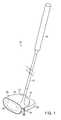
- FIG. 1is a perspective view of a golf club with fasteners according to an illustrative aspect.
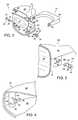
- FIG. 2is an exploded view of the club head of the golf club of FIG. 1 .
- FIG. 3is an exploded view of a portion of the club head of the golf club of FIG. 1 .
- FIG. 4is a perspective view of a portion of the club head of the golf club of FIG. 1 .
- FIG. 5is a section view of a portion of the club head of the golf club of FIG. 1 .
- FIG. 6is a section view of an alternative embodiment of a portion of the club head of the golf club of FIG. 1 .
- FIG. 7is a perspective rear view of an alternative embodiment of the face plate of the club head of the golf club of FIG. 1 .
- FIG. 8is a perspective view of another aspect of a sole portion of a golf club head shown with a weight attached thereto.
- FIG. 9is a section view of an alternative embodiment of components of a club head of a golf club secured to one another with a fastener.
- FIG. 10is a perspective view of an alternative embodiment of a golf club with a fastener according to an illustrative aspect.
- FIG. 1An illustrative embodiment of a golf club 10 is shown in FIG. 1 and includes a shaft 12 and a golf club head 14 attached to shaft 12 .
- Golf club head 14may be any driver, wood, or the like.
- Shaft 12 of golf club 10may be made of various materials, such as steel, aluminum, titanium, graphite, or composite materials, as well as alloys and/or combinations thereof, including materials that are conventionally known and used in the art.
- the shaft 12may be attached to the club head 14 in any desired manner, including in conventional manners known and used in the art (e.g., via adhesives or cements at a hosel element, via fusing techniques (e.g., welding, brazing, soldering, etc.), via threads or other mechanical connectors, via friction fits, via retaining element structures, etc.).
- a grip or other handle element 16is positioned on shaft 12 to provide a golfer with a slip resistant surface with which to grasp golf club shaft 12 .
- Grip element 16may be attached to shaft 12 in any desired manner, including in conventional manners known and used in the art (e.g., via adhesives or cements, via threads or other mechanical connectors, via fusing techniques, via friction fits, via retaining element structures, etc.).
- FIG. 2illustrates an embodiment of golf club head 14 in more detail.
- Club head 14includes a plurality of components. As illustrated, this example golf club head 14 includes a face plate 18 and a body member 20 positioned behind face plate 18 .
- Body member 20includes at least two body components. In the illustrated embodiment, body member 20 includes a crown portion 22 , a sole portion 24 and a skirt 26 extending rearwardly from crown portion 22 and sole portion 24 . It is to be appreciated that body member 20 may include any number of components.
- Body member 20 of golf club head 14may be constructed from a wide variety of different materials, including materials conventionally known and used in the art, such as steel, titanium, aluminum, magnesium, nickel, tungsten, alloys of these metals, graphite, polymers, fiber-reinforced materials, or composites, or combinations thereof. Other suitable materials will become readily apparent to those skilled in the art, given the benefit of this disclosure. It is to be appreciated that crown portion 22 and sole portion 24 may be formed of the same or different material.
- the component elements of club head 14are removably secured to one another with at least one fastener 28 .
- two fasteners 28are shown securing the components of club head 14 to one another. It is to be appreciated that one or more than two fasteners 28 can be used to removably secure the components of club head 14 to one another.
- Fasteners 28serve to removably secure face plate 18 to body member 20 upon being turned a portion of a revolution, as described in greater detail below.
- the use of partial revolution fasteners 28allows a user or other individual to quickly and easily assemble a golf club head 14 formed of multiple components.
- a usercould be fitted in a shop for a golf club head that is optimized for their swing, and have that club assembled while in the shop.
- the use of partial revolution fastenersallows the components of the club head to be quickly assembled and removably secured together.
- partial revolution fastenersallows the club head to be disassembled at some future time, which allows for additional components to be added, such as weights, for example, or for select components to be replaced with other components.
- additional componentssuch as weights, for example, or for select components to be replaced with other components.
- Fasteners 28are inserted through through-holes, or apertures formed in the components of club head 14 , and then turned a partial revolution, which securely engages fastener 28 with the components of body member 20 .
- fasteners 28may include a shaft 30 , which is shown as being substantially cylindrical in this embodiment. It is to be appreciated that shaft 30 need not be cylindrical, and may, for example, be rectangular in cross-section, or have any other regular or non-regular polygon cross-section.
- a head 32is positioned at a first end of shaft 30 , and at least one flange 34 extending outwardly from shaft 30 at its second end. In the illustrated embodiment, a pair of opposed flanges 34 extend outwardly from the second end of shaft 30 . It is to be appreciated that shaft 30 may include any number of flanges 34 .
- flanges 34can be of any geometric design, shape, number, or size to create an interference fit when flanges 34 engage body member 20 . Further, it is to be appreciated that fastener 28 can be turned any portion of a revolution, for example, a quarter revolution.
- fasteners 28are shown being used to secure the components of club head 14 together. It is to be appreciated that any number of fasteners 28 could be used to secure the components of club head 14 together.
- head 32is shown with a Phillips head slot for use with a screwdriver. It is to be appreciated that head 32 could also have a slot head recess for use with a flat screwdriver, a hexagonal socket for use with a hex key, or any other shape suitable for mating with a corresponding tool. Head 32 could also be turned with a wrench in order to tighten fastener 28 . Suitable types and shapes of head 32 will become readily apparent to those skilled in the art, given the benefit of this disclosure.
- first pair of apertures 36is formed in skirt 26
- second pair of apertures 38is formed in sole portion 24
- third pair of apertures 40is formed in crown portion 22 .
- first apertures 36 , second apertures 38 , and third apertures 40are aligned coaxially with one another.
- Fasteners 28are then inserted through the apertures on opposed sides of club head 14 and turned a portion of a revolution. In the illustrated embodiment, with shaft 30 including two flanges 34 , fasteners 28 may be turned a quarter revolution. At this point, fasteners 28 are engaged with body member, as most clearly seen in FIG. 4 .
- each apertureincludes a central section 42 and a pair of opposed slots 44 extending outwardly from central section 42 .
- shaft 30passes through central section 42 and flanges 34 pass through slots 44 .
- fastener 28is fully inserted into aperture 40 , it is turned a portion of a revolution such that flanges 34 are no longer aligned with slots 44 and are abutting a surface of crown portion 22 , as seen in FIG. 4 .
- Fasteners 28now cannot be pulled back through the apertures due to the engagement of flanges 34 with corresponding surfaces of body member 20 .
- slots 44extend substantially horizontally outward from central section 42 of aperture 40 .
- flanges 34extend substantially vertically away from shaft 30 , as seen in FIG. 4 .
- slots 44can be of any geometric design, shape, number, or size, and can extend in any direction, and are not limited to the horizontally extending direction shown in this embodiment.
- crown portion 22includes a pair of first registration members that engage a pair of second registration members on sole portion 24 so as to facilitate the alignment and registration of crown portion 22 and sole portion 24 with one another.
- the first registration membersare first pillars 46 , which extend downwardly from a lower surface of crown portion 22 .
- First pillars 46are cylindrical members that receive a projection 48 formed on the corresponding second registration members, which are seen as second pillars 50 in the illustrated embodiment.
- Second pillars 50extend upwardly from an upper surface of sole portion 24 .
- the engagement of projections 48 of second pillars 50 with first pillars 46serves to help align and register crown portion 22 and sole portion 24 with respect to one another.
- Each aperture 40is formed in one of pillars 46 .
- skirt 26is seated in a recess 52 formed about the periphery of sole portion 24 and rests upon a shoulder 54 of sole portion 24 . It is to be appreciated that in other embodiments, such a recess for receiving skirt 26 could be formed in crown portion 22 .
- face plate 18 and body member 20engage and are interlocked with one another, that is, elements formed on face plate 18 and body member 20 engage with one another in interlocking fashion such that face plate 18 and body member 20 are restricted from moving with respect to one another.
- a projection 56is formed about the periphery of face plate 18 .
- a corresponding or mating first groove or first recess 58is formed in a lower surface of the front edge of crown portion 22 and receives a portion of projection 56 .
- a second groove or second recess 60is formed in an upper surface of a front edge of sole portion 24 and receives a portion of projection 56 .
- face plate 18may have a groove or recess 62 formed about its periphery that engages with a mating and corresponding first projection 64 formed in a lower surface of the front edge of crown portion 22 and a mating and corresponding second projection 66 formed in an upper surface of the front edge of sole portion 24 .
- face plate 18may include a pair of apertures 68 through which fasteners 28 extend, thereby directly securing face plate 18 to body member 20 by way of fasteners 28 .
- a pair of flanges 70extends rearwardly from face plate 18 , with apertures 68 being formed in flanges 70 .
- additional componentscan be added to club head 14 .
- an additional weight 72can be removably secured to the other components of club head 14 by way of fasteners 28 .
- club head 14is shown with weight 72 positioned within sole portion 24 of body member 20 .
- a pair of apertures 74is provided in weight 72 , with fasteners 28 extending through apertures 74 .
- weight 72includes a pair of forwardly extending arms 76 , with an aperture 74 being formed in each arm 76 .
- weight 72can have any desired shape and that weight 72 can be positioned at any location on club head 14 , including being positioned in or on skirt 26 , or at any other location on the exterior of body member 20 . It is also to be appreciated that more than one weight 72 can be secured to club head 14 , and that each weight 72 can be positioned at any desired location within or on club head 14 .
- club head 14can be quickly and easily assembled and disassembled through the use of fasteners 28 , the component parts of club head 14 can be quickly and easily interchanged or replaced with other components. Accordingly, a user can have a variety of different club head components that can be substituted for one another for a variety of reasons. For example, a club component can be selected based on playing conditions expected to be encountered (e.g., different course conditions, different weather conditions, different wind conditions, etc.), the type of golf ball being used, and the skill or ability of the golfer. As a user improves, they may adapt a different playing style, and being able to replace the club head component allows them to modify their club without purchasing an entirely new club.
- playing conditions expected to be encounterede.g., different course conditions, different weather conditions, different wind conditions, etc.
- club head 14all aspects of the geometry or mass properties of club head 14 can be modified through the use of the interchangeable club head components including, but not limited to, the club head's shape, weight, weight distribution, bounce angle, center of gravity, moment of inertia, material of which it is formed, and appearance, which can alter the center of gravity, moment of inertia, and/or other “feel” characteristics of club head 14 .
- fasteners 28can be positioned at any location on club head 14 .
- fasteners 28extend vertically through body member 20 of club head 14 .
- apertures 40extend vertically through crown portion 22 and apertures 38 extend vertically through sole portion 24 .
- Recesses 78 formed in the lower surface of sole portion 24receive flanges 34 at the second end of fastener 28 .
- a pair of flanges 80extends inwardly from skirt 26 , with apertures 36 extending downwardly through flanges 80 .
- Shaft 30 of fasteners 28extend through apertures 40 of crown portion 24 , apertures 36 of skirt 26 , and apertures 38 of sole portion 24 .
- fasteners 28can be positioned at any location with club head 14 .
- the components of club head 14can be removably secured to one another with a single fastener 28 .
- the single fastener 28would extend through both apertures 36 in skirt 26 , through both apertures 38 in sole portion 24 , and through both apertures 40 in crown portion 22 .
- the plurality of components that make up club head 14can reliably be secured to one another quickly and easily.
Landscapes
- Health & Medical Sciences (AREA)
- General Health & Medical Sciences (AREA)
- Physical Education & Sports Medicine (AREA)
- Life Sciences & Earth Sciences (AREA)
- Engineering & Computer Science (AREA)
- Wood Science & Technology (AREA)
- Golf Clubs (AREA)
Abstract
Description
Claims (22)
Priority Applications (5)
| Application Number | Priority Date | Filing Date | Title |
|---|---|---|---|
| US12/205,264US7878919B2 (en) | 2008-09-05 | 2008-09-05 | Golf club head and golf club assembly with fastener |
| PCT/US2009/055839WO2010028114A2 (en) | 2008-09-05 | 2009-09-03 | Golf club head and golf club assembly with fastener |
| CN200980134252.0ACN102137695B (en) | 2008-09-05 | 2009-09-03 | Golf club assembly and golf club head with fastener |
| JP2011526184AJP5604624B2 (en) | 2008-09-05 | 2009-09-03 | Golf club head and golf club assembly having fasteners |
| EP09792213.2AEP2331215B1 (en) | 2008-09-05 | 2009-09-03 | Golf club head and golf club assembly with fastener |
Applications Claiming Priority (1)
| Application Number | Priority Date | Filing Date | Title |
|---|---|---|---|
| US12/205,264US7878919B2 (en) | 2008-09-05 | 2008-09-05 | Golf club head and golf club assembly with fastener |
Publications (2)
| Publication Number | Publication Date |
|---|---|
| US20100062872A1 US20100062872A1 (en) | 2010-03-11 |
| US7878919B2true US7878919B2 (en) | 2011-02-01 |
Family
ID=41796508
Family Applications (1)
| Application Number | Title | Priority Date | Filing Date |
|---|---|---|---|
| US12/205,264Expired - Fee RelatedUS7878919B2 (en) | 2008-09-05 | 2008-09-05 | Golf club head and golf club assembly with fastener |
Country Status (5)
| Country | Link |
|---|---|
| US (1) | US7878919B2 (en) |
| EP (1) | EP2331215B1 (en) |
| JP (1) | JP5604624B2 (en) |
| CN (1) | CN102137695B (en) |
| WO (1) | WO2010028114A2 (en) |
Cited By (4)
| Publication number | Priority date | Publication date | Assignee | Title |
|---|---|---|---|---|
| US20160175668A1 (en)* | 2012-06-08 | 2016-06-23 | Callaway Golf Company | Golf club head with center of gravity adjustability |
| US9413150B2 (en)* | 2014-06-26 | 2016-08-09 | Eaton Corporation | Locking mechanism for control box |
| US9579548B2 (en) | 2012-05-31 | 2017-02-28 | Nike, Inc. | Golf club head or other ball striking device with face having modulus variance |
| US11865415B2 (en) | 2008-12-18 | 2024-01-09 | Karsten Manufacturing Corporation | Golf clubs and golf club heads having interchangeable rear body members |
Families Citing this family (11)
| Publication number | Priority date | Publication date | Assignee | Title |
|---|---|---|---|---|
| US9072949B2 (en)* | 2008-12-18 | 2015-07-07 | Nike, Inc. | Golf clubs and golf club heads having interchangeable rear body members |
| US8821309B2 (en) | 2009-05-13 | 2014-09-02 | Nike, Inc. | Golf club assembly and golf club with aerodynamic features |
| US8366565B2 (en) | 2009-05-13 | 2013-02-05 | Nike, Inc. | Golf club assembly and golf club with aerodynamic features |
| US8162775B2 (en) | 2009-05-13 | 2012-04-24 | Nike, Inc. | Golf club assembly and golf club with aerodynamic features |
| US8758156B2 (en) | 2009-05-13 | 2014-06-24 | Nike, Inc. | Golf club assembly and golf club with aerodynamic features |
| US8702531B2 (en) | 2009-05-13 | 2014-04-22 | Nike, Inc. | Golf club assembly and golf club with aerodynamic hosel |
| US8435135B2 (en)* | 2010-05-28 | 2013-05-07 | Nike, Inc. | Golf club head or other ball striking device having removable or interchangeable body member |
| US8932149B2 (en) | 2012-05-31 | 2015-01-13 | Nike, Inc. | Golf club assembly and golf club with aerodynamic features |
| US8870679B2 (en) | 2012-05-31 | 2014-10-28 | Nike, Inc. | Golf club assembly and golf club with aerodynamic features |
| US9750991B2 (en) | 2013-03-07 | 2017-09-05 | Taylor Made Golf Company, Inc. | Golf club head |
| CN114542560B (en)* | 2022-02-15 | 2024-04-05 | 南京雨霖春科技咨询有限公司 | Touch-press separated golf club assembling equipment |
Citations (25)
| Publication number | Priority date | Publication date | Assignee | Title |
|---|---|---|---|---|
| US1349805A (en) | 1919-03-27 | 1920-08-17 | Charles W Booth | Golf-club |
| US2385180A (en)* | 1943-09-30 | 1945-09-18 | Camloc Fastener Corp | Fastener |
| US2620539A (en)* | 1950-03-04 | 1952-12-09 | Illinois Tool Works | Fastener device |
| US4884808A (en) | 1988-03-24 | 1989-12-05 | Retzer Jerome E | Golf club with head having exchangeable face plates |
| US5582553A (en)* | 1994-07-05 | 1996-12-10 | Goldwin Golf U.S.A., Inc. | Golf club head with interlocking sole plate |
| WO1997035645A1 (en) | 1996-03-27 | 1997-10-02 | Demarini Sports, Inc. | Golf club head |
| US5695296A (en)* | 1995-02-20 | 1997-12-09 | Nifco, Inc. | Connector for plates |
| US5911638A (en)* | 1994-07-05 | 1999-06-15 | Goldwin Golf Usa, Inc. | Golf club head with adjustable weighting |
| US6217461B1 (en) | 1996-04-30 | 2001-04-17 | Taylor Made Golf Company, Inc. | Golf club head |
| US6238303B1 (en) | 1996-12-03 | 2001-05-29 | John Fite | Golf putter with adjustable characteristics |
| US20020022532A1 (en) | 2000-01-14 | 2002-02-21 | Tucker Richard B.C. | Golf club having replaceable striking surface attachments and method for replacing same |
| US20020098908A1 (en) | 2001-01-25 | 2002-07-25 | James Robert T. | Putter heads having enhanced rotational moment of inertia and manufacturing method |
| US6659883B2 (en) | 2001-01-19 | 2003-12-09 | Karsten Manufacturing Corporation | Customizable golf putter head |
| US6769724B2 (en)* | 2000-12-07 | 2004-08-03 | Detewe-Deutsche Telephonwerke Aktiengesellschaft & Co. | Multi-part housing and device for locking interconnected housing parts of a multi-part housing |
| US6769853B2 (en)* | 2001-02-16 | 2004-08-03 | Peugeot Citroen Automobiles Sa | Holding device for fixing a car body element to the structure of a motor vehicle |
| US20050227780A1 (en) | 2004-04-13 | 2005-10-13 | Cover Brian M | Adjustable golf club |
| US20070111813A1 (en) | 2004-01-16 | 2007-05-17 | David Edel | Putter with Interchangeable Faceplate |
| WO2007076304A2 (en) | 2005-12-29 | 2007-07-05 | Callaway Golf Company | Golf club head with customizable center of gravity |
| US20070167253A1 (en) | 2006-01-17 | 2007-07-19 | Sizemore Bruce E Jr | Putter head |
| US20070184915A1 (en) | 2006-02-08 | 2007-08-09 | Peter Mansfield | Interchangeable putter system |
| US20070191138A1 (en) | 2006-01-04 | 2007-08-16 | Acushnet Company | Curved golf putter |
| US20070207875A1 (en) | 2006-03-03 | 2007-09-06 | Roger Cleveland Golf Company, Inc. | GM2 exchange putter |
| US7326121B2 (en) | 2004-08-03 | 2008-02-05 | Roake James P | Golf putter |
| US20080153619A1 (en) | 2006-11-21 | 2008-06-26 | Tucker Richard B C | Golf Club Having A Cam-Locked Insert |
| US20090203465A1 (en)* | 2008-02-11 | 2009-08-13 | Nike, Inc. | Golf Clubs and Golf Club Heads Having Targeted Weighting Characteristics |
Family Cites Families (5)
| Publication number | Priority date | Publication date | Assignee | Title |
|---|---|---|---|---|
| JPH09215786A (en)* | 1996-02-15 | 1997-08-19 | Mitsubishi Materials Corp | Golf club head and production thereof |
| US6149534A (en)* | 1998-11-02 | 2000-11-21 | Taylor Made Golf Company, Inc. | Bi-metallic golf club head with single plane interface |
| JP3628662B2 (en)* | 2002-02-22 | 2005-03-16 | 株式会社アシックス | Club head |
| CN2548668Y (en)* | 2002-05-27 | 2003-05-07 | 陈晴祺 | Composite golf wood club head |
| US6860818B2 (en)* | 2002-06-17 | 2005-03-01 | Callaway Golf Company | Golf club head with peripheral weighting |
- 2008
- 2008-09-05USUS12/205,264patent/US7878919B2/ennot_activeExpired - Fee Related
- 2009
- 2009-09-03CNCN200980134252.0Apatent/CN102137695B/ennot_activeExpired - Fee Related
- 2009-09-03JPJP2011526184Apatent/JP5604624B2/ennot_activeExpired - Fee Related
- 2009-09-03WOPCT/US2009/055839patent/WO2010028114A2/enactiveApplication Filing
- 2009-09-03EPEP09792213.2Apatent/EP2331215B1/ennot_activeNot-in-force
Patent Citations (28)
| Publication number | Priority date | Publication date | Assignee | Title |
|---|---|---|---|---|
| US1349805A (en) | 1919-03-27 | 1920-08-17 | Charles W Booth | Golf-club |
| US2385180A (en)* | 1943-09-30 | 1945-09-18 | Camloc Fastener Corp | Fastener |
| US2620539A (en)* | 1950-03-04 | 1952-12-09 | Illinois Tool Works | Fastener device |
| US4884808A (en) | 1988-03-24 | 1989-12-05 | Retzer Jerome E | Golf club with head having exchangeable face plates |
| US5582553A (en)* | 1994-07-05 | 1996-12-10 | Goldwin Golf U.S.A., Inc. | Golf club head with interlocking sole plate |
| US5911638A (en)* | 1994-07-05 | 1999-06-15 | Goldwin Golf Usa, Inc. | Golf club head with adjustable weighting |
| US5695296A (en)* | 1995-02-20 | 1997-12-09 | Nifco, Inc. | Connector for plates |
| US5863261A (en)* | 1996-03-27 | 1999-01-26 | Demarini Sports, Inc. | Golf club head with elastically deforming face and back plates |
| WO1997035645A1 (en) | 1996-03-27 | 1997-10-02 | Demarini Sports, Inc. | Golf club head |
| US6217461B1 (en) | 1996-04-30 | 2001-04-17 | Taylor Made Golf Company, Inc. | Golf club head |
| US6238303B1 (en) | 1996-12-03 | 2001-05-29 | John Fite | Golf putter with adjustable characteristics |
| US20020022532A1 (en) | 2000-01-14 | 2002-02-21 | Tucker Richard B.C. | Golf club having replaceable striking surface attachments and method for replacing same |
| US20050130757A1 (en) | 2000-01-14 | 2005-06-16 | Tucker Richard B.Sr. | Golf club having replaceable striking surface attachments and method for replacing same |
| US6769724B2 (en)* | 2000-12-07 | 2004-08-03 | Detewe-Deutsche Telephonwerke Aktiengesellschaft & Co. | Multi-part housing and device for locking interconnected housing parts of a multi-part housing |
| US6663502B2 (en) | 2001-01-19 | 2003-12-16 | Karsten Manufacturing Corporation | Customizable golf putter head |
| US6659883B2 (en) | 2001-01-19 | 2003-12-09 | Karsten Manufacturing Corporation | Customizable golf putter head |
| US20020098908A1 (en) | 2001-01-25 | 2002-07-25 | James Robert T. | Putter heads having enhanced rotational moment of inertia and manufacturing method |
| US6769853B2 (en)* | 2001-02-16 | 2004-08-03 | Peugeot Citroen Automobiles Sa | Holding device for fixing a car body element to the structure of a motor vehicle |
| US20070111813A1 (en) | 2004-01-16 | 2007-05-17 | David Edel | Putter with Interchangeable Faceplate |
| US20050227780A1 (en) | 2004-04-13 | 2005-10-13 | Cover Brian M | Adjustable golf club |
| US7326121B2 (en) | 2004-08-03 | 2008-02-05 | Roake James P | Golf putter |
| WO2007076304A2 (en) | 2005-12-29 | 2007-07-05 | Callaway Golf Company | Golf club head with customizable center of gravity |
| US20070191138A1 (en) | 2006-01-04 | 2007-08-16 | Acushnet Company | Curved golf putter |
| US20070167253A1 (en) | 2006-01-17 | 2007-07-19 | Sizemore Bruce E Jr | Putter head |
| US20070184915A1 (en) | 2006-02-08 | 2007-08-09 | Peter Mansfield | Interchangeable putter system |
| US20070207875A1 (en) | 2006-03-03 | 2007-09-06 | Roger Cleveland Golf Company, Inc. | GM2 exchange putter |
| US20080153619A1 (en) | 2006-11-21 | 2008-06-26 | Tucker Richard B C | Golf Club Having A Cam-Locked Insert |
| US20090203465A1 (en)* | 2008-02-11 | 2009-08-13 | Nike, Inc. | Golf Clubs and Golf Club Heads Having Targeted Weighting Characteristics |
Non-Patent Citations (1)
| Title |
|---|
| International Search Report and Written Opinion issued Apr. 7, 2010 in corresponding PCT Application No. PCT/US2009/055839. |
Cited By (10)
| Publication number | Priority date | Publication date | Assignee | Title |
|---|---|---|---|---|
| US11865415B2 (en) | 2008-12-18 | 2024-01-09 | Karsten Manufacturing Corporation | Golf clubs and golf club heads having interchangeable rear body members |
| US9579548B2 (en) | 2012-05-31 | 2017-02-28 | Nike, Inc. | Golf club head or other ball striking device with face having modulus variance |
| US10080935B2 (en) | 2012-05-31 | 2018-09-25 | Karsten Manufacturing Corporation | Golf club head or other ball striking device with face having modulus variance |
| US10427013B2 (en) | 2012-05-31 | 2019-10-01 | Karsten Manufacturing Corporation | Golf club head or other ball striking device with face having modulus variance |
| US11358036B2 (en) | 2012-05-31 | 2022-06-14 | Karsten Manufacturing Corporation | Golf club head or other ball striking device with face having modulus variance |
| US20160175668A1 (en)* | 2012-06-08 | 2016-06-23 | Callaway Golf Company | Golf club head with center of gravity adjustability |
| US9682299B2 (en)* | 2012-06-08 | 2017-06-20 | Callaway Golf Company | Golf club head with center of gravity adjustability |
| US20170246518A1 (en)* | 2012-06-08 | 2017-08-31 | Callaway Golf Company | Golf Club Head With Center of Gravity Adjustability |
| US10004958B2 (en)* | 2012-06-08 | 2018-06-26 | Callaway Golf Company | Golf club head with center of gravity adjustability |
| US9413150B2 (en)* | 2014-06-26 | 2016-08-09 | Eaton Corporation | Locking mechanism for control box |
Also Published As
| Publication number | Publication date |
|---|---|
| JP2012501745A (en) | 2012-01-26 |
| WO2010028114A2 (en) | 2010-03-11 |
| JP5604624B2 (en) | 2014-10-08 |
| CN102137695A (en) | 2011-07-27 |
| US20100062872A1 (en) | 2010-03-11 |
| CN102137695B (en) | 2014-12-03 |
| EP2331215B1 (en) | 2016-10-26 |
| EP2331215A2 (en) | 2011-06-15 |
| WO2010028114A3 (en) | 2010-05-20 |
Similar Documents
| Publication | Publication Date | Title |
|---|---|---|
| US7878919B2 (en) | Golf club head and golf club assembly with fastener | |
| US8133129B2 (en) | Golf club and golf club head with interchangeable body component | |
| US7922603B2 (en) | Golf club assembly and golf club head with bar and weighted member | |
| US7871334B2 (en) | Golf club head and golf club with tension element and tensioning member | |
| US11819741B2 (en) | Golf club head and golf club head structures | |
| US9168438B2 (en) | Golf club and golf club head structures | |
| EP2485814B1 (en) | Golf clubs and golf club heads with adjustable center of gravity and moment of inertia characteristics | |
| JP5341993B2 (en) | Golf club weight elements | |
| US7993217B2 (en) | Curved golf putter | |
| US9233282B2 (en) | Golf clubs and gold club heads with adjustable center of gravity and moment of inertia characteristics |
Legal Events
| Date | Code | Title | Description |
|---|---|---|---|
| AS | Assignment | Owner name:BATTELLE MEMORIAL INSTITUTE,OHIO Free format text:ASSIGNMENT OF ASSIGNORS INTEREST;ASSIGNORS:PERRY, MARK J.;MOORE, MEGAN SESSLAR;YOUNG, MATTHEW S.;AND OTHERS;SIGNING DATES FROM 20080924 TO 20080930;REEL/FRAME:021685/0185 Owner name:NIKE USA, INC.,OREGON Free format text:ASSIGNMENT OF ASSIGNORS INTEREST;ASSIGNOR:BATELLE MEMORIAL INSTITUTE;REEL/FRAME:021685/0192 Effective date:20081004 Owner name:NIKE INC.,OREGON Free format text:ASSIGNMENT OF ASSIGNORS INTEREST;ASSIGNOR:NIKE USA, INC.;REEL/FRAME:021685/0196 Effective date:20081013 Owner name:BATTELLE MEMORIAL INSTITUTE, OHIO Free format text:ASSIGNMENT OF ASSIGNORS INTEREST;ASSIGNORS:PERRY, MARK J.;MOORE, MEGAN SESSLAR;YOUNG, MATTHEW S.;AND OTHERS;SIGNING DATES FROM 20080924 TO 20080930;REEL/FRAME:021685/0185 Owner name:NIKE USA, INC., OREGON Free format text:ASSIGNMENT OF ASSIGNORS INTEREST;ASSIGNOR:BATELLE MEMORIAL INSTITUTE;REEL/FRAME:021685/0192 Effective date:20081004 Owner name:NIKE INC., OREGON Free format text:ASSIGNMENT OF ASSIGNORS INTEREST;ASSIGNOR:NIKE USA, INC.;REEL/FRAME:021685/0196 Effective date:20081013 | |
| AS | Assignment | Owner name:NIKE USA, INC.,OREGON Free format text:CORRECTIVE ASSIGNMENT TO CORRECT THE ASSIGNOR: BATELLE MEMORIAL INSTITUTE SHOULD READ BATTELLE MEMORIAL INSTITUTE (CORRECT SPELLING) PREVIOUSLY RECORDED ON REEL 021685 FRAME 0192. ASSIGNOR(S) HEREBY CONFIRMS THE ASSIGNMENT;ASSIGNOR:BATTELLE MEMORIAL INSTITUTE;REEL/FRAME:021720/0725 Effective date:20081004 Owner name:NIKE USA, INC., OREGON Free format text:CORRECTIVE ASSIGNMENT TO CORRECT THE ASSIGNOR: BATELLE MEMORIAL INSTITUTE SHOULD READ BATTELLE MEMORIAL INSTITUTE (CORRECT SPELLING) PREVIOUSLY RECORDED ON REEL 021685 FRAME 0192. ASSIGNOR(S) HEREBY CONFIRMS THE ASSIGNMENT;ASSIGNOR:BATTELLE MEMORIAL INSTITUTE;REEL/FRAME:021720/0725 Effective date:20081004 | |
| STCF | Information on status: patent grant | Free format text:PATENTED CASE | |
| FPAY | Fee payment | Year of fee payment:4 | |
| AS | Assignment | Owner name:KARSTEN MANUFACTURING CORPORATION, ARIZONA Free format text:ASSIGNMENT OF ASSIGNORS INTEREST;ASSIGNOR:NIKE, INC.;REEL/FRAME:041823/0161 Effective date:20170127 | |
| MAFP | Maintenance fee payment | Free format text:PAYMENT OF MAINTENANCE FEE, 8TH YEAR, LARGE ENTITY (ORIGINAL EVENT CODE: M1552) Year of fee payment:8 | |
| FEPP | Fee payment procedure | Free format text:MAINTENANCE FEE REMINDER MAILED (ORIGINAL EVENT CODE: REM.); ENTITY STATUS OF PATENT OWNER: LARGE ENTITY | |
| LAPS | Lapse for failure to pay maintenance fees | Free format text:PATENT EXPIRED FOR FAILURE TO PAY MAINTENANCE FEES (ORIGINAL EVENT CODE: EXP.); ENTITY STATUS OF PATENT OWNER: LARGE ENTITY | |
| STCH | Information on status: patent discontinuation | Free format text:PATENT EXPIRED DUE TO NONPAYMENT OF MAINTENANCE FEES UNDER 37 CFR 1.362 | |
| FP | Lapsed due to failure to pay maintenance fee | Effective date:20230201 |