US7878866B1 - Connector assembly for vehicle charging - Google Patents
Connector assembly for vehicle chargingDownload PDFInfo
- Publication number
- US7878866B1 US7878866B1US12/829,490US82949010AUS7878866B1US 7878866 B1US7878866 B1US 7878866B1US 82949010 AUS82949010 AUS 82949010AUS 7878866 B1US7878866 B1US 7878866B1
- Authority
- US
- United States
- Prior art keywords
- series
- plug
- connector assembly
- handle
- tabs
- Prior art date
- Legal status (The legal status is an assumption and is not a legal conclusion. Google has not performed a legal analysis and makes no representation as to the accuracy of the status listed.)
- Expired - Fee Related
Links
Images


Classifications
- H—ELECTRICITY
- H01—ELECTRIC ELEMENTS
- H01R—ELECTRICALLY-CONDUCTIVE CONNECTIONS; STRUCTURAL ASSOCIATIONS OF A PLURALITY OF MUTUALLY-INSULATED ELECTRICAL CONNECTING ELEMENTS; COUPLING DEVICES; CURRENT COLLECTORS
- H01R13/00—Details of coupling devices of the kinds covered by groups H01R12/70 or H01R24/00 - H01R33/00
- H01R13/46—Bases; Cases
- H01R13/502—Bases; Cases composed of different pieces
- H01R13/506—Bases; Cases composed of different pieces assembled by snap action of the parts
- B—PERFORMING OPERATIONS; TRANSPORTING
- B60—VEHICLES IN GENERAL
- B60L—PROPULSION OF ELECTRICALLY-PROPELLED VEHICLES; SUPPLYING ELECTRIC POWER FOR AUXILIARY EQUIPMENT OF ELECTRICALLY-PROPELLED VEHICLES; ELECTRODYNAMIC BRAKE SYSTEMS FOR VEHICLES IN GENERAL; MAGNETIC SUSPENSION OR LEVITATION FOR VEHICLES; MONITORING OPERATING VARIABLES OF ELECTRICALLY-PROPELLED VEHICLES; ELECTRIC SAFETY DEVICES FOR ELECTRICALLY-PROPELLED VEHICLES
- B60L53/00—Methods of charging batteries, specially adapted for electric vehicles; Charging stations or on-board charging equipment therefor; Exchange of energy storage elements in electric vehicles
- B60L53/10—Methods of charging batteries, specially adapted for electric vehicles; Charging stations or on-board charging equipment therefor; Exchange of energy storage elements in electric vehicles characterised by the energy transfer between the charging station and the vehicle
- B60L53/14—Conductive energy transfer
- B60L53/16—Connectors, e.g. plugs or sockets, specially adapted for charging electric vehicles
- B—PERFORMING OPERATIONS; TRANSPORTING
- B60—VEHICLES IN GENERAL
- B60L—PROPULSION OF ELECTRICALLY-PROPELLED VEHICLES; SUPPLYING ELECTRIC POWER FOR AUXILIARY EQUIPMENT OF ELECTRICALLY-PROPELLED VEHICLES; ELECTRODYNAMIC BRAKE SYSTEMS FOR VEHICLES IN GENERAL; MAGNETIC SUSPENSION OR LEVITATION FOR VEHICLES; MONITORING OPERATING VARIABLES OF ELECTRICALLY-PROPELLED VEHICLES; ELECTRIC SAFETY DEVICES FOR ELECTRICALLY-PROPELLED VEHICLES
- B60L53/00—Methods of charging batteries, specially adapted for electric vehicles; Charging stations or on-board charging equipment therefor; Exchange of energy storage elements in electric vehicles
- B60L53/10—Methods of charging batteries, specially adapted for electric vehicles; Charging stations or on-board charging equipment therefor; Exchange of energy storage elements in electric vehicles characterised by the energy transfer between the charging station and the vehicle
- B60L53/14—Conductive energy transfer
- B60L53/18—Cables specially adapted for charging electric vehicles
- H—ELECTRICITY
- H01—ELECTRIC ELEMENTS
- H01R—ELECTRICALLY-CONDUCTIVE CONNECTIONS; STRUCTURAL ASSOCIATIONS OF A PLURALITY OF MUTUALLY-INSULATED ELECTRICAL CONNECTING ELEMENTS; COUPLING DEVICES; CURRENT COLLECTORS
- H01R13/00—Details of coupling devices of the kinds covered by groups H01R12/70 or H01R24/00 - H01R33/00
- H01R13/62—Means for facilitating engagement or disengagement of coupling parts or for holding them in engagement
- H01R13/629—Additional means for facilitating engagement or disengagement of coupling parts, e.g. aligning or guiding means, levers, gas pressure electrical locking indicators, manufacturing tolerances
- H01R13/633—Additional means for facilitating engagement or disengagement of coupling parts, e.g. aligning or guiding means, levers, gas pressure electrical locking indicators, manufacturing tolerances for disengagement only
- H—ELECTRICITY
- H01—ELECTRIC ELEMENTS
- H01R—ELECTRICALLY-CONDUCTIVE CONNECTIONS; STRUCTURAL ASSOCIATIONS OF A PLURALITY OF MUTUALLY-INSULATED ELECTRICAL CONNECTING ELEMENTS; COUPLING DEVICES; CURRENT COLLECTORS
- H01R13/00—Details of coupling devices of the kinds covered by groups H01R12/70 or H01R24/00 - H01R33/00
- H01R13/58—Means for relieving strain on wire connection, e.g. cord grip, for avoiding loosening of connections between wires and terminals within a coupling device terminating a cable
- H01R13/5804—Means for relieving strain on wire connection, e.g. cord grip, for avoiding loosening of connections between wires and terminals within a coupling device terminating a cable comprising a separate cable clamping part
- Y—GENERAL TAGGING OF NEW TECHNOLOGICAL DEVELOPMENTS; GENERAL TAGGING OF CROSS-SECTIONAL TECHNOLOGIES SPANNING OVER SEVERAL SECTIONS OF THE IPC; TECHNICAL SUBJECTS COVERED BY FORMER USPC CROSS-REFERENCE ART COLLECTIONS [XRACs] AND DIGESTS
- Y02—TECHNOLOGIES OR APPLICATIONS FOR MITIGATION OR ADAPTATION AGAINST CLIMATE CHANGE
- Y02T—CLIMATE CHANGE MITIGATION TECHNOLOGIES RELATED TO TRANSPORTATION
- Y02T10/00—Road transport of goods or passengers
- Y02T10/60—Other road transportation technologies with climate change mitigation effect
- Y02T10/70—Energy storage systems for electromobility, e.g. batteries
- Y—GENERAL TAGGING OF NEW TECHNOLOGICAL DEVELOPMENTS; GENERAL TAGGING OF CROSS-SECTIONAL TECHNOLOGIES SPANNING OVER SEVERAL SECTIONS OF THE IPC; TECHNICAL SUBJECTS COVERED BY FORMER USPC CROSS-REFERENCE ART COLLECTIONS [XRACs] AND DIGESTS
- Y02—TECHNOLOGIES OR APPLICATIONS FOR MITIGATION OR ADAPTATION AGAINST CLIMATE CHANGE
- Y02T—CLIMATE CHANGE MITIGATION TECHNOLOGIES RELATED TO TRANSPORTATION
- Y02T10/00—Road transport of goods or passengers
- Y02T10/60—Other road transportation technologies with climate change mitigation effect
- Y02T10/7072—Electromobility specific charging systems or methods for batteries, ultracapacitors, supercapacitors or double-layer capacitors
- Y—GENERAL TAGGING OF NEW TECHNOLOGICAL DEVELOPMENTS; GENERAL TAGGING OF CROSS-SECTIONAL TECHNOLOGIES SPANNING OVER SEVERAL SECTIONS OF THE IPC; TECHNICAL SUBJECTS COVERED BY FORMER USPC CROSS-REFERENCE ART COLLECTIONS [XRACs] AND DIGESTS
- Y02—TECHNOLOGIES OR APPLICATIONS FOR MITIGATION OR ADAPTATION AGAINST CLIMATE CHANGE
- Y02T—CLIMATE CHANGE MITIGATION TECHNOLOGIES RELATED TO TRANSPORTATION
- Y02T90/00—Enabling technologies or technologies with a potential or indirect contribution to GHG emissions mitigation
- Y02T90/10—Technologies relating to charging of electric vehicles
- Y02T90/12—Electric charging stations
- Y—GENERAL TAGGING OF NEW TECHNOLOGICAL DEVELOPMENTS; GENERAL TAGGING OF CROSS-SECTIONAL TECHNOLOGIES SPANNING OVER SEVERAL SECTIONS OF THE IPC; TECHNICAL SUBJECTS COVERED BY FORMER USPC CROSS-REFERENCE ART COLLECTIONS [XRACs] AND DIGESTS
- Y02—TECHNOLOGIES OR APPLICATIONS FOR MITIGATION OR ADAPTATION AGAINST CLIMATE CHANGE
- Y02T—CLIMATE CHANGE MITIGATION TECHNOLOGIES RELATED TO TRANSPORTATION
- Y02T90/00—Enabling technologies or technologies with a potential or indirect contribution to GHG emissions mitigation
- Y02T90/10—Technologies relating to charging of electric vehicles
- Y02T90/14—Plug-in electric vehicles
- Y—GENERAL TAGGING OF NEW TECHNOLOGICAL DEVELOPMENTS; GENERAL TAGGING OF CROSS-SECTIONAL TECHNOLOGIES SPANNING OVER SEVERAL SECTIONS OF THE IPC; TECHNICAL SUBJECTS COVERED BY FORMER USPC CROSS-REFERENCE ART COLLECTIONS [XRACs] AND DIGESTS
- Y10—TECHNICAL SUBJECTS COVERED BY FORMER USPC
- Y10S—TECHNICAL SUBJECTS COVERED BY FORMER USPC CROSS-REFERENCE ART COLLECTIONS [XRACs] AND DIGESTS
- Y10S439/00—Electrical connectors
- Y10S439/901—Connector hood or shell
- Y10S439/903—Special latch for insert
- Y—GENERAL TAGGING OF NEW TECHNOLOGICAL DEVELOPMENTS; GENERAL TAGGING OF CROSS-SECTIONAL TECHNOLOGIES SPANNING OVER SEVERAL SECTIONS OF THE IPC; TECHNICAL SUBJECTS COVERED BY FORMER USPC CROSS-REFERENCE ART COLLECTIONS [XRACs] AND DIGESTS
- Y10—TECHNICAL SUBJECTS COVERED BY FORMER USPC
- Y10S—TECHNICAL SUBJECTS COVERED BY FORMER USPC CROSS-REFERENCE ART COLLECTIONS [XRACs] AND DIGESTS
- Y10S439/00—Electrical connectors
- Y10S439/923—Separation or disconnection aid
Definitions
- One or more embodimentsrelate to a connector assembly for facilitating the electrical charging of a vehicle.
- Electric vehicles and many hybrid vehiclesinclude a receptacle that is electrically connected to a vehicle battery.
- the receptaclereceives an electrical connector that is coupled to a power supply for charging the vehicle battery.
- FIG. 1is a schematic view of a connector assembly for electric vehicle charging according to at least one embodiment of the present invention
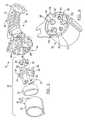
- FIG. 2is a side perspective view of the connector assembly of FIG. 1 , illustrated partially disassembled;
- FIG. 3is a side perspective view of the connector assembly of FIG. 2 , illustrated further disassembled;
- FIG. 4is an enlarged partial section view of the connector assembly of FIG. 2 taken along section line 4 - 4 ;
- FIG. 5is an exploded side perspective view of the connector assembly of FIG. 2 ;
- FIG. 6is a rear perspective view of a plug of the connector assembly of FIG. 2 ;
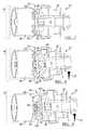
- FIG. 7is a top view of the connector assembly of FIG. 2 , illustrated in an unloaded position
- FIG. 8is another top view of the connector assembly of FIG. 2 , illustrated in a loaded position.
- FIG. 9is yet another top view of the connector assembly of FIG. 2 , illustrated in another loaded position.
- a connector assembly for facilitating the electric charging of a vehicleis illustrated in accordance with an embodiment and is generally referenced by numeral 10 .
- a connector assembly having a break-away featureis provided for releasably coupling an electrical power supply to a “plug-in” electric or hybrid vehicle.
- the connector assembly 10is coupled to a charging cable 12 and a power supply 14 for transferring electrical power.
- the connector assembly 10is attached to the end of a charging cable 12 .
- the charging cable 12extends from the power supply 14 .
- the power supply 14represents an AC electrical power supply, such as a standard residential power circuit.
- a “plug-in” electric or hybrid vehicle 16is coupled to the power supply 14 for electrical charging.
- the vehicle 16includes a vehicle charging receptacle 18 and a battery 20 for receiving electrical power.
- the vehicle charging receptacle 18is mounted to be externally accessible from the vehicle 16 .
- the vehicle charging receptacle 18receives the connector assembly 10 .
- the battery 20is electrically connected to the charging receptacle 18 for storing electrical power.
- the vehicle 16 or the power supply 14may also include a converter (not shown) for converting AC to DC electrical power for storage in the battery 20 .
- FIG. 1depicts the vehicle 16 driving away from the power supply 14 .
- the vehicle 16Once the vehicle 16 has traveled far enough to remove any slack within the charging cable 12 , tensile forces develop within the charging cable, which result in a transverse load 22 acting upon an intermediate portion of the connector assembly 10 .
- This “drive away” eventis provided for illustrative purposes, however other situations could result in such a transverse load 22 applied to the connector assembly 10 . For example an individual could inadvertently walk into the assembly 10 , or drop a heavy object on the assembly 10 , while it is connected.
- FIG. 2illustrates the connector assembly 10 of FIG. 1 , without an outer shell 24 .
- the outer shell 24helps retain and enclose the components of the connector assembly 10 .
- the connector assembly 10includes an elongate handle 26 and a plug 28 connected to each other for facilitating electrical charging of the vehicle 16 .
- the connector assembly 10includes a break-away feature 30 whereby the handle 26 disconnects from the plug 28 when the assembly 10 is subjected to a predetermined transverse load 22 .
- the break-away feature 30also minimizes damage to the vehicle 16 and the power supply 14 during transverse loading. Typically, damage to the vehicle 16 or power supply 14 is more expensive to repair, than damage to the connector assembly 10 .
- the handle 26includes an inlet 32 for receiving the charging cable 12 .
- the inlet 32is formed at a proximal end of the handle 26 , away from the plus 28 .
- the charging cable 12may include a flexible grommet 34 attached to an end of the cable 12 for providing strain relief and a seal between the cable 12 and the inlet 32 .
- the plug 28engages the vehicle charging receptacle 18 .
- An interface between the plug 28 and the vehicle charging receptacle 18may be specified in an effort to standardize the connection throughout the electric vehicle industry.
- SAESociety of Automotive Engineers
- SAE-J1772which is hereby incorporated by reference.
- the connector assembly 10is not limited by this SAE specification and may be utilized for applications specifying other interface requirements.
- the connector assembly 10includes a latching mechanism 36 for attaching the connector assembly 10 to the charging receptacle 18 .
- the latching mechanism 36is designed to maintain the electrical connection to the vehicle 16 while charging the battery 20 .
- the latching mechanism 36also prevents the connector assembly 10 from simply disconnecting from the vehicle 16 when a load is applied to the connector assembly 10 .
- the latching mechanism 36includes a lever 38 , a link 40 and a trigger 42 coupled to one another.
- the lever 38is pivotally coupled to an upper portion of the handle 26 .
- the link 40is pivotally coupled to an intermediate portion of the handle 26 .
- the link 40is coupled to the lever 38 and pivots in an opposite direction as the lever 38 .
- a lip 41extends along an upper periphery of the trigger 42 for engaging the link 40 .
- a compression springis provided for biasing the lever 38 in a latched position (as illustrated in FIG. 2 ).
- the spring 43is located between a distal portion of the lever 38 and an upper portion of the handle 26 .
- the lip 41pivots the link 40 counter-clockwise, which in turn pivots the lever 38 clockwise and away from the plug 28 .
- the lever 38pivots clockwise, it compresses the spring 43 and unlatches the connector assembly 10 from the vehicle receptacle 18 .
- the spring 43pivots the lever 38 back into the latched position.
- the latching mechanism 36allows a user to selectively attach the connector assembly 10 to the vehicle charging receptacle 18 .
- the elongate handle 26includes the inlet 32 , an outlet 44 and a body 46 formed between the inlet 32 and outlet 44 .
- the body 46forms a longitudinal internal cavity 48 for supporting the charging cable 12 .
- the charging cableincludes a sheathing 50 formed around an electrical harness 52 .
- the sheathing 50insulates and protects the harness 52 along the length of the cable 12 outside of the connector assembly 10 .
- the sheathing 50ends at the inlet 32 of the handle 26 and the harness 52 extends along the internal cavity 48 .
- the portion of the harness 52 located within the cavity 48is encapsulated by a molded material 54 which is formed by a low-pressure molding process.
- the molded material 54includes Macromelt® material by Henkel Corporation of Madison Heights, Mich.
- the molded material 54helps insulate and seal the harness 52 .
- Additional electronic components, such as a position sensor 56 and LED 58may also be encapsulated within the body 46 by the molded material 54 .
- the outlet 44 of the handle 26forms a generally cylindrical pocket 60 that is longitudinally recessed toward the body 46 .
- the pocket 60encloses a free-length portion 62 of the electrical harness 52 .
- a female wire terminal 64is attached or soldered to the end of each free-length portion 62 , and secured within the plug 28 .
- the pocket 60does not include any molded material 54 , therefore the free-length portion 62 of the harness 52 is allowed some flexibility in movement.
- the outlet 44includes a series of slots 66 for attaching the handle 26 and the plug 28 to each other.
- the slots 66are formed through an external wall 68 of the pocket 60 .
- the illustrated embodimentincludes an outlet 44 with three equally dimensioned slots 66 , such that each slot 66 has a common length and width. Additionally, each slot 66 is equally spaced about a circumference of the outlet 44 at 120 degrees intervals.
- other embodiments of the connector assembly 10contemplate more than three slots 66 ; slots 66 having differing dimensions with respect to one another; and irregular spacing between adjacent slots 66 .
- the handle 26may be formed by a clamshell structure with a front portion 70 and a rear portion 72 attached to one another by transverse fasteners. Additionally an adhesive or gasket may be applied to an outer periphery of each portion 70 and 72 to seal the internal cavity 48 .
- the plug 28includes a terminal cover 74 , a wiper seal 76 and a shroud 78 coupled to one another for sealing the plug 28 .
- the terminal cover 74includes a disc-shaped base 79 with a first side surface 80 and a second side surface 82 .
- the first side surface 80is oriented adjacent to the outlet 44 of the handle 26 and opposite the second side surface 82 .
- a ring 84is formed along a circumference of the base 79 and longitudinally extends in opposing directions.
- the outer diameter of the ring 84is stepped such that the portion of the ring that extends beyond the second side surface 82 has a smaller outer diameter that the portion of the ring 84 that extends beyond the first side surface 80 .
- the wiper seal 76is generally cylindrically shaped and positioned to abut the ring 84 adjacent to the second side surface 82 .
- the shroud 78attaches to the terminal cover 74 to retain the seal 76 .
- the shroud 78is tubular and generally cylindrically shaped.
- the shroud 78includes a recess 86 for receiving the stepped outer diameter of the cover 74 .
- the recess 86is formed along a proximal end of the inner diameter of the shroud 78 at a proximal end of the plug 28 .
- the shroud 78also includes a groove 88 formed along an intermediate portion of the inner diameter which extends to the recess 86 .
- the groove 88 and the ring 84collectively form a radial channel 90 for longitudinally retaining the seal 76 within the plug 28 .
- the terminal cover 74 and shroud 78are attached to each other by an ultrasonic weld at the interface between the recess 86 and the ring 84 .
- the terminal cover 74secures the female terminals 64 .
- a series of cylindrical terminal receptacles 92extend transversely from the second side surface 82 of the plug 28 .
- Each terminal receptacle 92forms a terminal cavity 94 for receiving a female terminal 64 .
- the connector assembly 10may also include a back plate 96 that attaches to the first side surface 80 of the terminal cover 74 for retaining the female terminals 64 , each within a terminal cavity 94 .
- the illustrated embodiment of the connector assembly 10depicts a five-terminal plug 28 that is designed according to the interface requirements of the SAE-J1772 specification.
- the terminal cover 74also includes a series of tabs 98 for attaching the plug 28 to the handle 26 .
- the series of tabs 98longitudinally extend from a peripheral edge of the base 79 .
- the tabs 98are aligned with the slots 66 and received into the pocket 60 of the handle 26 .
- Each tab 98is formed with a longitudinal length, a lateral curved width and a thickness.
- a transverse projection 100is formed along the width of each tab 98 .
- Each projection 100extends radially outward from an intermediate portion of the length of the tab 98 .
- the projections 100are sized for engaging a corresponding slot 66 with an interference fit.
- An interference fitensures line contact at opposing sides of the slot 66 to distribute applied loads.
- the projections 100are formed with a rounded profile.
- the projections 100are formed with a two millimeter radius and the slots 66 are formed with a width less than four millimeters, for providing an interference fit.
- the illustrated embodimentincludes three tabs 98 , where each tab 98 is equally spaced about the circumference of the base 79 .
- the tabs 98may be spaced at 120 degree intervals, with one tab 98 oriented in a lower “6-o'clock” position.
- other embodiments of the connector assembly 10contemplate more than three tabs 98 ; tabs 98 having differing dimensions with respect to one another; and irregular spacing between adjacent tabs 98 .
- FIGS. 7-9illustrate the break-away feature 30 of the connector assembly 10 .
- the tabs 98 and the slots 66are configured to provide a structural weak point for failure when the connector assembly 10 is subjected to a predetermined transverse load 22 applied to an intermediate portion of the assembly 10 .
- the tabs 98 and slots 66are designed to “fail” such that the handle 26 disconnects from the plug 28 . Such failure may be achieved by plastic or elastic deformation of at least one of the tabs 98 and or the slots 66 .
- the connector assembly 10is configured as a frangible connector assembly 10 where the tabs 98 are configured to fracture when the assembly 10 is subjected to the predetermined load 22 .
- FIGS. 7-9represent loading on the connector assembly 10 when the plug 28 is constrained by the charging receptacle 18 (illustrated in phantom).
- FIG. 7illustrates a top view of the connector assembly 10 in a connected and unloaded position.
- the handle 26is connected to the plug 28 and each projection 100 is fully engaged with the corresponding slot 66 . Additionally, the free-length portion of the harness (not shown) is partially compressed and flexible.
- FIG. 8illustrates a top view of the connector assembly 10 in a partially connected and loaded position.
- the transverse load 22is applied to an intermediate portion of the handle 26 .
- the tabs 98elastically deform in the direction of the load 22 , and the handle 26 pivots counterclockwise. Although the tabs 98 are deformed, the projections 100 still engage the slots 66 .
- FIG. 9illustrates the connector assembly 10 in a disconnected and loaded position. As the tabs 98 deform beyond the positions illustrated in FIG. 8 , the projections 100 disengage from the slots 66 , and the handle 26 disconnects from the plug 28 .
- FIG. 9depicts an upper tab 98 that has elastically deformed and has returned to its original position, and a lower tab that has plastically deformed and fractured. Additionally, the free-length portion 62 of the harness has extended to allow the projections 100 to fully disengage the slots 66 for facilitating disconnection of the handle 26 .
- the break-away feature 30may be designed to withstand a predetermined transverse load 22 applied to the connector assembly 10 before the handle 26 disconnects.
- the performance of the break-away feature 30may be adjusted to accommodate different loading requirements by adjusting dimensions and material properties of the tabs 98 and slots 66 .
- the connector assembly 10is configured to break-away or fail when a transverse load between 160-300 Newtons is applied to an intermediate portion of the connector assembly 10 .
- a minimum load requirementis necessary to prevent the connector assembly from failing during normal operating conditions.
- a maximum load requirementprevents damage being sustained by the power supply 14 or vehicle 16 during loading.
- both the handle 26 and tabs 98are molded from a nylon material such as Ultramid®, a Polyamide 6/6 from BASF of Wyandotte, Mich. Additionally, the tabs 98 are designed to have common dimensions with a thickness between 2-3 mm.
- Other embodiments of the connector assembly 10contemplate the handle 26 and the tabs 98 being formed from other polymers such as polypropylene or acetal.
Landscapes
- Engineering & Computer Science (AREA)
- Power Engineering (AREA)
- Transportation (AREA)
- Mechanical Engineering (AREA)
- Connector Housings Or Holding Contact Members (AREA)
- Details Of Connecting Devices For Male And Female Coupling (AREA)
- Electric Propulsion And Braking For Vehicles (AREA)
Abstract
Description
Claims (20)
Priority Applications (4)
| Application Number | Priority Date | Filing Date | Title |
|---|---|---|---|
| US12/829,490US7878866B1 (en) | 2010-07-02 | 2010-07-02 | Connector assembly for vehicle charging |
| US12/969,798US8206184B2 (en) | 2010-07-02 | 2010-12-16 | Connector assembly for vehicle charging |
| DE102011078348.2ADE102011078348B4 (en) | 2010-07-02 | 2011-06-29 | Connector device with break-away structure for charging a vehicle |
| CN201110185444.3ACN102394427B (en) | 2010-07-02 | 2011-06-30 | Connector assembly for vehicle charging |
Applications Claiming Priority (2)
| Application Number | Priority Date | Filing Date | Title |
|---|---|---|---|
| US12/829,490US7878866B1 (en) | 2010-07-02 | 2010-07-02 | Connector assembly for vehicle charging |
| US12/969,798US8206184B2 (en) | 2010-07-02 | 2010-12-16 | Connector assembly for vehicle charging |
Related Child Applications (1)
| Application Number | Title | Priority Date | Filing Date |
|---|---|---|---|
| US12/969,798ContinuationUS8206184B2 (en) | 2010-07-02 | 2010-12-16 | Connector assembly for vehicle charging |
Publications (1)
| Publication Number | Publication Date |
|---|---|
| US7878866B1true US7878866B1 (en) | 2011-02-01 |
Family
ID=45346965
Family Applications (2)
| Application Number | Title | Priority Date | Filing Date |
|---|---|---|---|
| US12/829,490Expired - Fee RelatedUS7878866B1 (en) | 2010-07-02 | 2010-07-02 | Connector assembly for vehicle charging |
| US12/969,798Expired - Fee RelatedUS8206184B2 (en) | 2010-07-02 | 2010-12-16 | Connector assembly for vehicle charging |
Family Applications After (1)
| Application Number | Title | Priority Date | Filing Date |
|---|---|---|---|
| US12/969,798Expired - Fee RelatedUS8206184B2 (en) | 2010-07-02 | 2010-12-16 | Connector assembly for vehicle charging |
Country Status (3)
| Country | Link |
|---|---|
| US (2) | US7878866B1 (en) |
| CN (1) | CN102394427B (en) |
| DE (1) | DE102011078348B4 (en) |
Cited By (56)
| Publication number | Priority date | Publication date | Assignee | Title |
|---|---|---|---|---|
| US20110212645A1 (en)* | 2010-03-01 | 2011-09-01 | Sumitomo Wiring Systems, Ltd. | Charging connector |
| US20110300736A1 (en)* | 2010-06-08 | 2011-12-08 | Kabushiki Kaisha Tokai Rika Denki Seisakusho | Locking device for power feeding plug |
| US20110318951A1 (en)* | 2010-06-28 | 2011-12-29 | David Armacost | Power input electrical connector |
| US20120003861A1 (en)* | 2010-07-02 | 2012-01-05 | Lear Corporation | connector assembly for vehicle charging |
| US20120126747A1 (en)* | 2010-11-19 | 2012-05-24 | Delphi Technologies, Inc. | Battery charger having non-contact electrical switch |
| US20120129369A1 (en)* | 2010-11-23 | 2012-05-24 | John Bogart | Electric vehicle breakaway cable |
| USD663692S1 (en) | 2010-12-30 | 2012-07-17 | General Cable Technologies Corporation | Electrical connector |
| DE102012200523A1 (en) | 2011-02-23 | 2012-08-23 | Lear Corporation | Thermal detection and control of a wall plug |
| USD666152S1 (en) | 2012-02-28 | 2012-08-28 | Lear Corporation | Connector assembly |
| WO2012121360A1 (en)* | 2011-03-04 | 2012-09-13 | Yazaki Corporation | Connector |
| DE102012206548A1 (en) | 2011-04-21 | 2012-10-25 | Lear Corporation | Proximity detection circuit for an on-board charger |
| DE102012007866A1 (en) | 2011-04-27 | 2012-10-31 | Lear Corp. | charger recording |
| DE102012209907A1 (en) | 2011-06-13 | 2012-12-13 | Lear Corp. | Plug assembly for electrical charging of electric vehicle, has casting material integrated with seal that is arranged at inlet to provide strain relief for cable bundle |
| CN102832484A (en)* | 2011-06-13 | 2012-12-19 | 李尔公司 | Connector assembly for vehicle charging |
| WO2012175573A1 (en)* | 2011-06-20 | 2012-12-27 | Fci Automotive Holding | Electrical multicontact plug and assembly method for charging system |
| USD675989S1 (en) | 2010-12-30 | 2013-02-12 | General Cable Technologies Corporation | Electrical connector |
| DE102012214685A1 (en) | 2011-08-22 | 2013-02-28 | Lear Corporation | connector assembly |
| DE102012016641A1 (en) | 2011-08-22 | 2013-02-28 | Lear Corporation | Connector assembly and terminal holder |
| US8408944B1 (en) | 2011-10-31 | 2013-04-02 | Lear Corporation | Scalable connection system for parallel wiring circuits |
| US8410369B2 (en)* | 2010-07-09 | 2013-04-02 | Chargepoint, Inc. | Breakaway mechanism for charging cables of electric vehicle charging stations |
| WO2012168488A3 (en)* | 2011-06-09 | 2013-04-25 | Huf Hülsbeck & Fürst Gmbh & Co. Kg | Locking apparatus for electric charging cables or flaps |
| DE102012019886A1 (en) | 2011-10-31 | 2013-05-02 | Lear Corporation | Electrical connection and socket assembly |
| DE102012220379A1 (en) | 2011-11-10 | 2013-05-16 | Lear Corporation | Control pilot detection circuit |
| DE102012220351A1 (en) | 2011-11-10 | 2013-05-16 | Lear Corporation | Proximity detection circuit with short-circuit protection |
| US20130260595A1 (en)* | 2012-03-27 | 2013-10-03 | Honda Motor Co., Ltd. | Charging device for electrically driven vehicle |
| US8562365B2 (en) | 2010-12-30 | 2013-10-22 | General Cable Technologies Corporation | Laminous multi-polymeric high amperage over-molded connector assembly for plug-in hybrid electric vehicle charging |
| US8568155B2 (en) | 2010-12-30 | 2013-10-29 | General Cable Technologies Corporation | Laminous multi-polymeric high amperage over-molded connector assembly for plug-in hybrid electric vehicle charging |
| DE102013010285A1 (en) | 2012-06-19 | 2013-12-19 | Lear Corp. | Electrical socket component for vehicle charging system for electrically charging battery of e.g. electric car, has annular coil spring provided in electrical contact with conductive body to receive electrical plug connector within socket |
| US20130337702A1 (en)* | 2012-06-19 | 2013-12-19 | Lear Corporation | Electrical receptacle assembly |
| WO2014001206A1 (en)* | 2012-06-29 | 2014-01-03 | Phoenix Contact Gmbh & Co. Kg | Plug having a contact socket and protective cover |
| US20140038463A1 (en)* | 2012-08-02 | 2014-02-06 | Lear Corporation | Submergible fused receptacle assembly for a vehicle charging inlet |
| US8753136B2 (en)* | 2010-09-30 | 2014-06-17 | Kabushiki Kaisha Tokai Rika Denki Seisakusho | Power feeding plug locking device |
| USD707179S1 (en) | 2010-12-30 | 2014-06-17 | General Cable Technologies Corporation | Electrical connector |
| US20140197793A1 (en)* | 2011-09-16 | 2014-07-17 | Bayerische Motoren Werke Aktiengesellschaft | Charging Apparatus for a Vehicle with Seven Electrical Contacts |
| US20140322951A1 (en)* | 2012-01-17 | 2014-10-30 | Yazaki Corporation | Electrical connector |
| US20140335711A1 (en)* | 2012-09-28 | 2014-11-13 | Atlantic Great Dane, Inc. | Power supply system including panel with safety release |
| US20150147919A1 (en)* | 2013-11-28 | 2015-05-28 | Phoenix Contact Gmbh & Co. Kg | Charging cable connector |
| US20150155656A1 (en)* | 2012-08-06 | 2015-06-04 | Yazaki Corporation | Charging connector |
| US20150224887A1 (en)* | 2012-10-05 | 2015-08-13 | Audi Ag | Module system for a charging apparatus, charging apparatus and vehicle including a charging apparatus constructed from the module system |
| US20150258905A1 (en)* | 2012-10-12 | 2015-09-17 | Yazaki Corporation | Charging inlet device |
| US20150295344A1 (en)* | 2012-10-25 | 2015-10-15 | Yazaki Corporation | Charging connector |
| US9187290B2 (en) | 2012-09-14 | 2015-11-17 | Lear Corporation | Cordset assembly |
| US9211798B2 (en) | 2011-07-28 | 2015-12-15 | Lear Corporation | Multistage power supply system and method for providing uninterrupted power to vehicle circuitry |
| US20160020555A1 (en)* | 2013-03-28 | 2016-01-21 | Yazaki Corporation | Charging connector |
| US20160104967A1 (en)* | 2014-10-13 | 2016-04-14 | Sumitomo Wiring Systems, Ltd. | Charging connector and method of mounting the same |
| US9365116B2 (en) | 2012-07-23 | 2016-06-14 | Ford Global Technologies, Llc | Vehicle recharging station and support devices |
| US9440538B2 (en) | 2011-11-11 | 2016-09-13 | Lear Corporation | Housekeeping circuit having trickle charge capabilities |
| FR3041822A1 (en)* | 2015-09-24 | 2017-03-31 | Commissariat Energie Atomique | PLUG FOR ELECTRIC CABLE |
| US20170149160A1 (en)* | 2015-11-25 | 2017-05-25 | Odu Gmbh & Co. Kg | Damping element for providing axial damping in a plug-in connector |
| US9899821B2 (en) | 2014-06-24 | 2018-02-20 | Lear Corporation | Cordset assembly |
| US20180170196A1 (en)* | 2016-12-20 | 2018-06-21 | Suying Electrcnics (Dong Guan) Co., Ltd. | Charging gun with replaceable plug and assembly method thereof |
| US20220324342A1 (en)* | 2021-04-12 | 2022-10-13 | Advanced Connectek Inc. | Electro mechanical or electrical connector for use in electric vehicle |
| US20220376423A1 (en)* | 2021-05-18 | 2022-11-24 | Yura Co., Ltd. | Charging connector for vehicle |
| US20220379749A1 (en)* | 2021-05-26 | 2022-12-01 | Rivian Ip Holdings, Llc | Charge coupler safety interlock systems and methods |
| US11554682B2 (en)* | 2018-07-11 | 2023-01-17 | Bayerische Motoren Werke Aktiengesellschaft | Charging device for charging a battery of an electrically operated motor vehicle |
| CN118893994A (en)* | 2024-10-08 | 2024-11-05 | 洛阳硕力信新能源科技有限公司 | Anti-drag car charging pile |
Families Citing this family (22)
| Publication number | Priority date | Publication date | Assignee | Title |
|---|---|---|---|---|
| JP5486398B2 (en)* | 2010-05-12 | 2014-05-07 | 株式会社東海理化電機製作所 | Power supply plug lock device |
| JP5486397B2 (en)* | 2010-05-12 | 2014-05-07 | 株式会社東海理化電機製作所 | Power supply plug lock device |
| DE112012006779B4 (en)* | 2012-08-06 | 2022-05-12 | Toyota Jidosha Kabushiki Kaisha | Access |
| DE112013005072T5 (en) | 2012-10-19 | 2015-07-02 | Lear Corporation | Electrical connector assembly |
| US20140120786A1 (en) | 2012-11-01 | 2014-05-01 | Avx Corporation | Single element wire to board connector |
| US8721376B1 (en) | 2012-11-01 | 2014-05-13 | Avx Corporation | Single element wire to board connector |
| US9743091B2 (en)* | 2012-12-17 | 2017-08-22 | Lg Electronics Inc. | Method for encoding/decoding image, and device using same |
| US8986019B2 (en)* | 2013-04-22 | 2015-03-24 | Asm Ip Holding B.V. | Connector with air extraction |
| JP6281820B2 (en)* | 2014-04-14 | 2018-02-21 | パナソニックIpマネジメント株式会社 | Charging connector |
| US9391386B2 (en) | 2014-10-06 | 2016-07-12 | Avx Corporation | Caged poke home contact |
| CN104882713B (en)* | 2015-06-15 | 2017-03-08 | 南京康尼新能源汽车零部件有限公司 | A kind of grasping type operation and the charging electric vehicle rifle of monolithic construction |
| DE102015114138B4 (en)* | 2015-08-26 | 2022-05-25 | Phoenix Contact E-Mobility Gmbh | Connector part with a locking element |
| CN105513552A (en)* | 2016-01-26 | 2016-04-20 | 京东方科技集团股份有限公司 | Driving circuit, driving method and display device |
| DE102016105470A1 (en)* | 2016-03-23 | 2017-09-28 | Te Connectivity Germany Gmbh | Power electrical contact device; replaceable, power-electric contact module and power-electrical connector |
| DE102016112937B4 (en)* | 2016-07-14 | 2025-02-27 | Phoenix Contact E-Mobility Gmbh | connector part with a locking element |
| US10014615B2 (en) | 2016-09-19 | 2018-07-03 | Lear Corporation | Connector assemblies for vehicle charging |
| DE102017104123B3 (en) | 2017-02-28 | 2018-04-26 | Harting Electric Gmbh & Co. Kg | Protective separation device for a rectangular connector |
| US10320096B2 (en) | 2017-06-01 | 2019-06-11 | Avx Corporation | Flexing poke home contact |
| JP7084789B2 (en)* | 2018-06-14 | 2022-06-15 | 株式会社Subaru | Charging socket and bracket for charging socket |
| US10622762B1 (en)* | 2019-01-14 | 2020-04-14 | Te Connectivity Corporation | Electrical cable connectors with break-away constructions |
| KR102750546B1 (en)* | 2020-09-22 | 2025-01-06 | 현대자동차 주식회사 | Charging inlet assembly of vehicle |
| WO2024210891A1 (en)* | 2023-04-04 | 2024-10-10 | Itt Cannon Gmbh | Frame electric vehicle (ev) connector with overmolding |
Citations (16)
| Publication number | Priority date | Publication date | Assignee | Title |
|---|---|---|---|---|
| US4669791A (en)* | 1984-09-06 | 1987-06-02 | Integrated Circuit Systems, Ltd. | Connector apparatus |
| US4707046A (en)* | 1986-07-10 | 1987-11-17 | Liquidometer Corporation | Safety breakaway electrical connector construction |
| US5080600A (en) | 1989-09-07 | 1992-01-14 | Amp Incorporated | Breakaway electrical connector |
| US5344331A (en)* | 1993-01-15 | 1994-09-06 | Hubbell Incorporated | Electrical connector system, especially for electric vehicles |
| US5344330A (en)* | 1993-01-15 | 1994-09-06 | Hubbell Incorporated | Electrical connector assembly, especially for electric vehicle |
| US5346406A (en)* | 1993-04-30 | 1994-09-13 | Hubbell Incorporated | Electrical cable and connector assembly with safety pilot line disconnect, especially for electric vehicle |
| US5385480A (en)* | 1993-01-15 | 1995-01-31 | Hubell Incorporated | Electrical connector inlet assembly with break-away mechanism for electric vehicle |
| US5478250A (en) | 1993-01-15 | 1995-12-26 | Hubbell Incorporated | Electrical connector assembly, especially for electric vehicle |
| US5674086A (en) | 1992-12-18 | 1997-10-07 | Yazaki Corporation | Electrical connector |
| US5676560A (en) | 1994-12-01 | 1997-10-14 | Yazaki Corporation | Powder feed connector |
| US5751135A (en) | 1995-11-30 | 1998-05-12 | Yazaki Corporation | Charging connector for electric vehicle |
| US5816643A (en) | 1993-07-12 | 1998-10-06 | Sumitomo Wiring Systems, Ltd. | Charge coupling for electric vehicle |
| US5906500A (en) | 1996-10-04 | 1999-05-25 | Yazaki Corporation | Charging connector for electric vehicle |
| US6203354B1 (en) | 1998-07-22 | 2001-03-20 | Sumitomo Wiring Systems, Ltd. | Electrical connector having first and second connector members and locking structure therefor |
| US6511341B1 (en)* | 2001-07-23 | 2003-01-28 | Itt Manufacturing Enterprises, Inc. | Break-away device |
| US7052282B2 (en) | 2004-09-28 | 2006-05-30 | Phillips & Temro Industries, Inc. | Cord set with a breakable connector |
Family Cites Families (8)
| Publication number | Priority date | Publication date | Assignee | Title |
|---|---|---|---|---|
| US4109989A (en)* | 1975-06-10 | 1978-08-29 | Amp Incorporated | Environmentally sealed electrical connector |
| US4863397A (en)* | 1988-04-22 | 1989-09-05 | Hatch Jr William K | Expendable frangible electrical connector |
| CH683647A5 (en)* | 1992-05-19 | 1994-04-15 | Diamond Sa | Connector for joining optical fibres - has easily replaceable, breakable catch which ruptures under strain, for connecting plug to socket |
| US6231392B1 (en)* | 1997-10-01 | 2001-05-15 | Berg Technology, Inc. | Cable interconnection |
| US6257932B1 (en)* | 2000-05-01 | 2001-07-10 | Sony Corporation | Keyed electrical connector |
| DE20203788U1 (en)* | 2002-03-08 | 2002-06-06 | Anton Hummel Verwaltungs Gmbh, 79183 Waldkirch | Connector with a housing and with a clamping insert |
| WO2009035531A2 (en)* | 2007-09-07 | 2009-03-19 | Johnson Controls - Saft Advanced Power Solutions Llc | Battery charging system |
| US7878866B1 (en)* | 2010-07-02 | 2011-02-01 | Lear Corporation | Connector assembly for vehicle charging |
- 2010
- 2010-07-02USUS12/829,490patent/US7878866B1/ennot_activeExpired - Fee Related
- 2010-12-16USUS12/969,798patent/US8206184B2/ennot_activeExpired - Fee Related
- 2011
- 2011-06-29DEDE102011078348.2Apatent/DE102011078348B4/ennot_activeExpired - Fee Related
- 2011-06-30CNCN201110185444.3Apatent/CN102394427B/ennot_activeExpired - Fee Related
Patent Citations (16)
| Publication number | Priority date | Publication date | Assignee | Title |
|---|---|---|---|---|
| US4669791A (en)* | 1984-09-06 | 1987-06-02 | Integrated Circuit Systems, Ltd. | Connector apparatus |
| US4707046A (en)* | 1986-07-10 | 1987-11-17 | Liquidometer Corporation | Safety breakaway electrical connector construction |
| US5080600A (en) | 1989-09-07 | 1992-01-14 | Amp Incorporated | Breakaway electrical connector |
| US5674086A (en) | 1992-12-18 | 1997-10-07 | Yazaki Corporation | Electrical connector |
| US5344330A (en)* | 1993-01-15 | 1994-09-06 | Hubbell Incorporated | Electrical connector assembly, especially for electric vehicle |
| US5385480A (en)* | 1993-01-15 | 1995-01-31 | Hubell Incorporated | Electrical connector inlet assembly with break-away mechanism for electric vehicle |
| US5478250A (en) | 1993-01-15 | 1995-12-26 | Hubbell Incorporated | Electrical connector assembly, especially for electric vehicle |
| US5344331A (en)* | 1993-01-15 | 1994-09-06 | Hubbell Incorporated | Electrical connector system, especially for electric vehicles |
| US5346406A (en)* | 1993-04-30 | 1994-09-13 | Hubbell Incorporated | Electrical cable and connector assembly with safety pilot line disconnect, especially for electric vehicle |
| US5816643A (en) | 1993-07-12 | 1998-10-06 | Sumitomo Wiring Systems, Ltd. | Charge coupling for electric vehicle |
| US5676560A (en) | 1994-12-01 | 1997-10-14 | Yazaki Corporation | Powder feed connector |
| US5751135A (en) | 1995-11-30 | 1998-05-12 | Yazaki Corporation | Charging connector for electric vehicle |
| US5906500A (en) | 1996-10-04 | 1999-05-25 | Yazaki Corporation | Charging connector for electric vehicle |
| US6203354B1 (en) | 1998-07-22 | 2001-03-20 | Sumitomo Wiring Systems, Ltd. | Electrical connector having first and second connector members and locking structure therefor |
| US6511341B1 (en)* | 2001-07-23 | 2003-01-28 | Itt Manufacturing Enterprises, Inc. | Break-away device |
| US7052282B2 (en) | 2004-09-28 | 2006-05-30 | Phillips & Temro Industries, Inc. | Cord set with a breakable connector |
Non-Patent Citations (1)
| Title |
|---|
| SAE International, Surface Vehicle Recommended Practice, "SAE Electric Vehicle and Plug In Hybrid Electric Vehicle Conductive Charge Coupler," Aug. 2006, 51 pages. |
Cited By (95)
| Publication number | Priority date | Publication date | Assignee | Title |
|---|---|---|---|---|
| US8206171B2 (en)* | 2010-03-01 | 2012-06-26 | Sumitomo Wiring Systems, Ltd. | Charging connector |
| US20110212645A1 (en)* | 2010-03-01 | 2011-09-01 | Sumitomo Wiring Systems, Ltd. | Charging connector |
| US20110300736A1 (en)* | 2010-06-08 | 2011-12-08 | Kabushiki Kaisha Tokai Rika Denki Seisakusho | Locking device for power feeding plug |
| US8251734B2 (en)* | 2010-06-08 | 2012-08-28 | Kabushiki Kaisha Tokai Rika Denki Seisakusho | Locking device for power feeding plug |
| US20110318951A1 (en)* | 2010-06-28 | 2011-12-29 | David Armacost | Power input electrical connector |
| US8251732B2 (en)* | 2010-06-28 | 2012-08-28 | Maxi-Seal Harness Systems Inc. | Power input electrical connector |
| US20120003861A1 (en)* | 2010-07-02 | 2012-01-05 | Lear Corporation | connector assembly for vehicle charging |
| US8206184B2 (en)* | 2010-07-02 | 2012-06-26 | Lear Corporation | Connector assembly for vehicle charging |
| US8410369B2 (en)* | 2010-07-09 | 2013-04-02 | Chargepoint, Inc. | Breakaway mechanism for charging cables of electric vehicle charging stations |
| US8753136B2 (en)* | 2010-09-30 | 2014-06-17 | Kabushiki Kaisha Tokai Rika Denki Seisakusho | Power feeding plug locking device |
| US8573994B2 (en) | 2010-11-19 | 2013-11-05 | Delphi Technologies, Inc. | Connector handle for an electric vehicle battery charger |
| US20120126747A1 (en)* | 2010-11-19 | 2012-05-24 | Delphi Technologies, Inc. | Battery charger having non-contact electrical switch |
| US20120129369A1 (en)* | 2010-11-23 | 2012-05-24 | John Bogart | Electric vehicle breakaway cable |
| US8568155B2 (en) | 2010-12-30 | 2013-10-29 | General Cable Technologies Corporation | Laminous multi-polymeric high amperage over-molded connector assembly for plug-in hybrid electric vehicle charging |
| USD707179S1 (en) | 2010-12-30 | 2014-06-17 | General Cable Technologies Corporation | Electrical connector |
| US8562365B2 (en) | 2010-12-30 | 2013-10-22 | General Cable Technologies Corporation | Laminous multi-polymeric high amperage over-molded connector assembly for plug-in hybrid electric vehicle charging |
| USD663692S1 (en) | 2010-12-30 | 2012-07-17 | General Cable Technologies Corporation | Electrical connector |
| USD675989S1 (en) | 2010-12-30 | 2013-02-12 | General Cable Technologies Corporation | Electrical connector |
| DE102012200523A1 (en) | 2011-02-23 | 2012-08-23 | Lear Corporation | Thermal detection and control of a wall plug |
| DE102012200523B4 (en) | 2011-02-23 | 2025-02-06 | Lear Corporation | Thermal detection and control of a wall plug |
| WO2012121360A1 (en)* | 2011-03-04 | 2012-09-13 | Yazaki Corporation | Connector |
| US9054443B2 (en) | 2011-03-04 | 2015-06-09 | Yazaki Corporation | Connector having a case with a rib with a groove engaging a rib with protrusions on a housing |
| US9399402B2 (en) | 2011-04-21 | 2016-07-26 | Lear Corporation | Proximity detection circuit for on-board vehicle charger |
| DE102012206548A1 (en) | 2011-04-21 | 2012-10-25 | Lear Corporation | Proximity detection circuit for an on-board charger |
| US8668506B2 (en) | 2011-04-27 | 2014-03-11 | Lear Corporation | Charger receptacle |
| DE102012007866A1 (en) | 2011-04-27 | 2012-10-31 | Lear Corp. | charger recording |
| WO2012168488A3 (en)* | 2011-06-09 | 2013-04-25 | Huf Hülsbeck & Fürst Gmbh & Co. Kg | Locking apparatus for electric charging cables or flaps |
| CN103648835B (en)* | 2011-06-09 | 2016-09-07 | 霍弗·霍斯贝克及弗斯特两合公司 | For charging wire or the locking device of cover plate |
| CN103648835A (en)* | 2011-06-09 | 2014-03-19 | 霍弗·霍斯贝克及弗斯特两合公司 | Locking apparatus for electric charging cables or flaps |
| US9505312B2 (en) | 2011-06-09 | 2016-11-29 | Huf Hulsbeck & Furst Gmbh & Co. Kg | Locking apparatus for electric charging cables or flaps |
| CN102832484A (en)* | 2011-06-13 | 2012-12-19 | 李尔公司 | Connector assembly for vehicle charging |
| DE102012209907B4 (en)* | 2011-06-13 | 2017-09-28 | Lear Corp. | Plug arrangement for loading a vehicle and method for its assembly |
| DE102012209907A1 (en) | 2011-06-13 | 2012-12-13 | Lear Corp. | Plug assembly for electrical charging of electric vehicle, has casting material integrated with seal that is arranged at inlet to provide strain relief for cable bundle |
| CN102832484B (en)* | 2011-06-13 | 2015-03-18 | 李尔公司 | Connector assembly for vehicle charging |
| US8834202B2 (en) | 2011-06-13 | 2014-09-16 | Lear Corporation | Connector assembly for vehicle charging |
| WO2012175573A1 (en)* | 2011-06-20 | 2012-12-27 | Fci Automotive Holding | Electrical multicontact plug and assembly method for charging system |
| US9211798B2 (en) | 2011-07-28 | 2015-12-15 | Lear Corporation | Multistage power supply system and method for providing uninterrupted power to vehicle circuitry |
| DE102012016641A1 (en) | 2011-08-22 | 2013-02-28 | Lear Corporation | Connector assembly and terminal holder |
| DE102012016641B4 (en)* | 2011-08-22 | 2016-09-29 | Lear Corporation | Recording arrangement and connection holder |
| DE102012214685B4 (en)* | 2011-08-22 | 2017-01-05 | Lear Corporation | Connector assembly and connector housing assembly |
| US9793642B2 (en)* | 2011-08-22 | 2017-10-17 | Lear Corporation | Connector assembly |
| US20130052853A1 (en)* | 2011-08-22 | 2013-02-28 | Lear Corporation | Connector assembly |
| DE102012214685A1 (en) | 2011-08-22 | 2013-02-28 | Lear Corporation | connector assembly |
| US9333869B2 (en)* | 2011-09-16 | 2016-05-10 | Bayerische Motoren Werke Aktiengesellschaft | Charging apparatus for a vehicle with seven electrical contacts |
| US20140197793A1 (en)* | 2011-09-16 | 2014-07-17 | Bayerische Motoren Werke Aktiengesellschaft | Charging Apparatus for a Vehicle with Seven Electrical Contacts |
| US8408944B1 (en) | 2011-10-31 | 2013-04-02 | Lear Corporation | Scalable connection system for parallel wiring circuits |
| DE102012019886A1 (en) | 2011-10-31 | 2013-05-02 | Lear Corporation | Electrical connection and socket assembly |
| DE102012019886B4 (en)* | 2011-10-31 | 2015-09-17 | Lear Corporation | Socket assembly |
| US9233611B2 (en) | 2011-11-10 | 2016-01-12 | Lear Corporation | Proximity detection circuit having short protection |
| DE102012220351A1 (en) | 2011-11-10 | 2013-05-16 | Lear Corporation | Proximity detection circuit with short-circuit protection |
| DE102012220351B4 (en) | 2011-11-10 | 2022-09-15 | Lear Corporation | Proximity sensing circuitry with short circuit protection |
| DE102012220379A1 (en) | 2011-11-10 | 2013-05-16 | Lear Corporation | Control pilot detection circuit |
| US9440538B2 (en) | 2011-11-11 | 2016-09-13 | Lear Corporation | Housekeeping circuit having trickle charge capabilities |
| US20140322951A1 (en)* | 2012-01-17 | 2014-10-30 | Yazaki Corporation | Electrical connector |
| US9106015B2 (en)* | 2012-01-17 | 2015-08-11 | Yazaki Corporation | Electrical connector |
| USD666152S1 (en) | 2012-02-28 | 2012-08-28 | Lear Corporation | Connector assembly |
| USD690271S1 (en) | 2012-02-28 | 2013-09-24 | Lear Corporation | Connector assembly |
| USD677632S1 (en) | 2012-02-28 | 2013-03-12 | Lear Corporation | Connector assembly |
| US20130260595A1 (en)* | 2012-03-27 | 2013-10-03 | Honda Motor Co., Ltd. | Charging device for electrically driven vehicle |
| US8932072B2 (en)* | 2012-03-27 | 2015-01-13 | Honda Motor Co., Ltd. | Charging device for electrically driven vehicle |
| DE102013010285A1 (en) | 2012-06-19 | 2013-12-19 | Lear Corp. | Electrical socket component for vehicle charging system for electrically charging battery of e.g. electric car, has annular coil spring provided in electrical contact with conductive body to receive electrical plug connector within socket |
| US20130337702A1 (en)* | 2012-06-19 | 2013-12-19 | Lear Corporation | Electrical receptacle assembly |
| WO2014001206A1 (en)* | 2012-06-29 | 2014-01-03 | Phoenix Contact Gmbh & Co. Kg | Plug having a contact socket and protective cover |
| US9365116B2 (en) | 2012-07-23 | 2016-06-14 | Ford Global Technologies, Llc | Vehicle recharging station and support devices |
| US20140038463A1 (en)* | 2012-08-02 | 2014-02-06 | Lear Corporation | Submergible fused receptacle assembly for a vehicle charging inlet |
| US8956190B2 (en)* | 2012-08-02 | 2015-02-17 | Lear Corporation | Submergible fused receptacle assembly for a vehicle charging inlet |
| US9263830B2 (en)* | 2012-08-06 | 2016-02-16 | Yazaki Corporation | Charging connector |
| US20150155656A1 (en)* | 2012-08-06 | 2015-06-04 | Yazaki Corporation | Charging connector |
| US9187290B2 (en) | 2012-09-14 | 2015-11-17 | Lear Corporation | Cordset assembly |
| US20140335711A1 (en)* | 2012-09-28 | 2014-11-13 | Atlantic Great Dane, Inc. | Power supply system including panel with safety release |
| US9093788B2 (en)* | 2012-09-28 | 2015-07-28 | Atlantic Great Dane, Inc. | Power supply system including panel with safety release |
| US10179517B2 (en)* | 2012-10-05 | 2019-01-15 | Audi Ag | Module system for a charging apparatus, charging apparatus and vehicle including a charging apparatus constructed from the module system |
| US20150224887A1 (en)* | 2012-10-05 | 2015-08-13 | Audi Ag | Module system for a charging apparatus, charging apparatus and vehicle including a charging apparatus constructed from the module system |
| US20150258905A1 (en)* | 2012-10-12 | 2015-09-17 | Yazaki Corporation | Charging inlet device |
| US9463702B2 (en)* | 2012-10-12 | 2016-10-11 | Yazaki Corporation | Charging inlet device |
| US20150295344A1 (en)* | 2012-10-25 | 2015-10-15 | Yazaki Corporation | Charging connector |
| US20160020555A1 (en)* | 2013-03-28 | 2016-01-21 | Yazaki Corporation | Charging connector |
| US9509095B2 (en)* | 2013-03-28 | 2016-11-29 | Yazaki Corporation | Charging connector |
| US20150147919A1 (en)* | 2013-11-28 | 2015-05-28 | Phoenix Contact Gmbh & Co. Kg | Charging cable connector |
| US9461399B2 (en)* | 2013-11-28 | 2016-10-04 | Phoenix Contact E-Mobility Gmbh | Charging cable connector |
| US9899821B2 (en) | 2014-06-24 | 2018-02-20 | Lear Corporation | Cordset assembly |
| US20160104967A1 (en)* | 2014-10-13 | 2016-04-14 | Sumitomo Wiring Systems, Ltd. | Charging connector and method of mounting the same |
| US9601864B2 (en)* | 2014-10-13 | 2017-03-21 | Sumitomo Wiring Systems, Ltd. | Charging connector and method of mounting the same |
| FR3041822A1 (en)* | 2015-09-24 | 2017-03-31 | Commissariat Energie Atomique | PLUG FOR ELECTRIC CABLE |
| US20170149160A1 (en)* | 2015-11-25 | 2017-05-25 | Odu Gmbh & Co. Kg | Damping element for providing axial damping in a plug-in connector |
| US9941617B2 (en)* | 2015-11-25 | 2018-04-10 | Odu Gmbh & Co. Kg | Damping element for providing axial damping in a plug-in connector |
| US20180170196A1 (en)* | 2016-12-20 | 2018-06-21 | Suying Electrcnics (Dong Guan) Co., Ltd. | Charging gun with replaceable plug and assembly method thereof |
| US11554682B2 (en)* | 2018-07-11 | 2023-01-17 | Bayerische Motoren Werke Aktiengesellschaft | Charging device for charging a battery of an electrically operated motor vehicle |
| US20220324342A1 (en)* | 2021-04-12 | 2022-10-13 | Advanced Connectek Inc. | Electro mechanical or electrical connector for use in electric vehicle |
| US11996646B2 (en)* | 2021-05-18 | 2024-05-28 | Yura Co., Ltd. | Charging connector for vehicle |
| US20220376423A1 (en)* | 2021-05-18 | 2022-11-24 | Yura Co., Ltd. | Charging connector for vehicle |
| US11827113B2 (en)* | 2021-05-26 | 2023-11-28 | Rivian Ip Holdings, Llc | Charge coupler safety interlock systems and methods |
| US20220379749A1 (en)* | 2021-05-26 | 2022-12-01 | Rivian Ip Holdings, Llc | Charge coupler safety interlock systems and methods |
| CN118893994A (en)* | 2024-10-08 | 2024-11-05 | 洛阳硕力信新能源科技有限公司 | Anti-drag car charging pile |
| CN118893994B (en)* | 2024-10-08 | 2024-12-20 | 洛阳硕力信新能源科技有限公司 | Anti-drag car charging pile |
Also Published As
| Publication number | Publication date |
|---|---|
| US20120003861A1 (en) | 2012-01-05 |
| US8206184B2 (en) | 2012-06-26 |
| DE102011078348B4 (en) | 2016-06-02 |
| CN102394427A (en) | 2012-03-28 |
| CN102394427B (en) | 2014-08-20 |
| DE102011078348A1 (en) | 2012-01-05 |
Similar Documents
| Publication | Publication Date | Title |
|---|---|---|
| US7878866B1 (en) | Connector assembly for vehicle charging | |
| US9601864B2 (en) | Charging connector and method of mounting the same | |
| US8834202B2 (en) | Connector assembly for vehicle charging | |
| CN105518903B (en) | System, the method and apparatus that constant current relay for battery module controls | |
| EP2908385B1 (en) | Charging inlet device | |
| US20170207501A1 (en) | Thermistor assembly including elastomeric body | |
| US9601863B2 (en) | Device connector with reinforcing ribs | |
| CN102403619A (en) | Charging connector for electric vehicle | |
| US20110088944A1 (en) | Wire harness | |
| US20130224969A1 (en) | Charge inlet | |
| CN109818189B (en) | Connector for equipment | |
| US9666994B2 (en) | Direct-connect high voltage connector and connection structure thereof | |
| US8152540B2 (en) | Connector terminal protection cap and harness assembly | |
| CN102683942A (en) | Contact and receptacle assembly for a vehicle charging inlet | |
| US8894449B2 (en) | Terminal block | |
| CN100407506C (en) | Housing element with joint part | |
| EP1684388B1 (en) | Case member provided with connector part | |
| CN110318978B (en) | Vehicle-mounted electric compressor | |
| CN107453099B (en) | Vehicle electric connector assembly and connecting method | |
| US11260764B2 (en) | Plug device for a battery, battery and vehicle | |
| KR20120029916A (en) | Connector for charging in electric vehicle | |
| US10516243B2 (en) | Wire harness connecting structure for two circuit assemblies | |
| KR20170077453A (en) | Outlet connector for charging electric vehicle | |
| WO2017077025A1 (en) | Vehicle earth point connector | |
| CN112038788A (en) | Terminal strip with sealed terminal lugs |
Legal Events
| Date | Code | Title | Description |
|---|---|---|---|
| AS | Assignment | Owner name:LEAR CORPORATION, MICHIGAN Free format text:ASSIGNMENT OF ASSIGNORS INTEREST;ASSIGNORS:KWASNY, KEITH;POULIN, MARC;REEL/FRAME:024629/0929 Effective date:20100630 | |
| STCF | Information on status: patent grant | Free format text:PATENTED CASE | |
| AS | Assignment | Owner name:JPMORGAN CHASE BANK, N.A., AS ADMINISTRATIVE AGENT Free format text:SECURITY AGREEMENT;ASSIGNOR:LEAR CORPORATION;REEL/FRAME:026468/0182 Effective date:20110617 | |
| CC | Certificate of correction | ||
| AS | Assignment | Owner name:JPMORGAN CAHSE BANK, N.A., AS AGENT, ILLINOIS Free format text:SECURITY INTEREST;ASSIGNOR:LEAR CORPORATION;REEL/FRAME:030076/0016 Effective date:20130130 Owner name:JPMORGAN CHASE BANK, N.A., AS AGENT, ILLINOIS Free format text:SECURITY INTEREST;ASSIGNOR:LEAR CORPORATION;REEL/FRAME:030076/0016 Effective date:20130130 | |
| FPAY | Fee payment | Year of fee payment:4 | |
| SULP | Surcharge for late payment | ||
| AS | Assignment | Owner name:LEAR CORPORATION, MICHIGAN Free format text:RELEASE BY SECURED PARTY;ASSIGNOR:JPMORGAN CHASE BANK, N.A., AS AGENT;REEL/FRAME:037701/0318 Effective date:20160104 | |
| AS | Assignment | Owner name:LEAR CORPORATION, MICHIGAN Free format text:RELEASE BY SECURED PARTY;ASSIGNOR:JPMORGAN CHASE BANK, N.A., AS AGENT;REEL/FRAME:037702/0911 Effective date:20160104 | |
| MAFP | Maintenance fee payment | Free format text:PAYMENT OF MAINTENANCE FEE, 8TH YEAR, LARGE ENTITY (ORIGINAL EVENT CODE: M1552) Year of fee payment:8 | |
| FEPP | Fee payment procedure | Free format text:MAINTENANCE FEE REMINDER MAILED (ORIGINAL EVENT CODE: REM.); ENTITY STATUS OF PATENT OWNER: LARGE ENTITY | |
| LAPS | Lapse for failure to pay maintenance fees | Free format text:PATENT EXPIRED FOR FAILURE TO PAY MAINTENANCE FEES (ORIGINAL EVENT CODE: EXP.); ENTITY STATUS OF PATENT OWNER: LARGE ENTITY | |
| STCH | Information on status: patent discontinuation | Free format text:PATENT EXPIRED DUE TO NONPAYMENT OF MAINTENANCE FEES UNDER 37 CFR 1.362 | |
| FP | Lapsed due to failure to pay maintenance fee | Effective date:20230201 |