US7878849B2 - Extender for a separable insulated connector - Google Patents
Extender for a separable insulated connectorDownload PDFInfo
- Publication number
- US7878849B2 US7878849B2US12/082,717US8271708AUS7878849B2US 7878849 B2US7878849 B2US 7878849B2US 8271708 AUS8271708 AUS 8271708AUS 7878849 B2US7878849 B2US 7878849B2
- Authority
- US
- United States
- Prior art keywords
- extender
- connector
- conductive
- semi
- separable insulated
- Prior art date
- Legal status (The legal status is an assumption and is not a legal conclusion. Google has not performed a legal analysis and makes no representation as to the accuracy of the status listed.)
- Active
Links
- 239000004606Fillers/ExtendersSubstances0.000titleclaimsabstractdescription210
- 230000006835compressionEffects0.000claimsabstractdescription72
- 238000007906compressionMethods0.000claimsabstractdescription72
- 239000004020conductorSubstances0.000claimsdescription63
- 238000003780insertionMethods0.000claimsdescription25
- 230000037431insertionEffects0.000claimsdescription25
- 238000004891communicationMethods0.000claimsdescription22
- 229920002943EPDM rubberPolymers0.000claimsdescription9
- 239000006229carbon blackSubstances0.000claimsdescription5
- 239000000203mixtureSubstances0.000claimsdescription3
- 238000009826distributionMethods0.000description30
- 239000011810insulating materialSubstances0.000description16
- 230000005611electricityEffects0.000description14
- 238000000034methodMethods0.000description7
- 238000004519manufacturing processMethods0.000description6
- 239000000463materialSubstances0.000description5
- 238000012360testing methodMethods0.000description4
- 230000013011matingEffects0.000description3
- 230000001681protective effectEffects0.000description3
- RYGMFSIKBFXOCR-UHFFFAOYSA-NCopperChemical compound[Cu]RYGMFSIKBFXOCR-UHFFFAOYSA-N0.000description2
- 229910052802copperInorganic materials0.000description2
- 239000010949copperSubstances0.000description2
- 238000005520cutting processMethods0.000description2
- 229920001971elastomerPolymers0.000description2
- 238000009434installationMethods0.000description2
- 238000009413insulationMethods0.000description2
- 238000012986modificationMethods0.000description2
- 230000004048modificationEffects0.000description2
- 238000000465mouldingMethods0.000description2
- 238000013461designMethods0.000description1
- 238000005516engineering processMethods0.000description1
- 238000012546transferMethods0.000description1
Images


Classifications
- H—ELECTRICITY
- H02—GENERATION; CONVERSION OR DISTRIBUTION OF ELECTRIC POWER
- H02G—INSTALLATION OF ELECTRIC CABLES OR LINES, OR OF COMBINED OPTICAL AND ELECTRIC CABLES OR LINES
- H02G15/00—Cable fittings
- H02G15/08—Cable junctions
- H02G15/18—Cable junctions protected by sleeves, e.g. for communication cable
- H—ELECTRICITY
- H01—ELECTRIC ELEMENTS
- H01R—ELECTRICALLY-CONDUCTIVE CONNECTIONS; STRUCTURAL ASSOCIATIONS OF A PLURALITY OF MUTUALLY-INSULATED ELECTRICAL CONNECTING ELEMENTS; COUPLING DEVICES; CURRENT COLLECTORS
- H01R11/00—Individual connecting elements providing two or more spaced connecting locations for conductive members which are, or may be, thereby interconnected, e.g. end pieces for wires or cables supported by the wire or cable and having means for facilitating electrical connection to some other wire, terminal, or conductive member, blocks of binding posts
- H01R11/11—End pieces or tapping pieces for wires, supported by the wire and for facilitating electrical connection to some other wire, terminal or conductive member
- H01R11/26—End pieces terminating in a screw clamp, screw or nut
- H—ELECTRICITY
- H01—ELECTRIC ELEMENTS
- H01R—ELECTRICALLY-CONDUCTIVE CONNECTIONS; STRUCTURAL ASSOCIATIONS OF A PLURALITY OF MUTUALLY-INSULATED ELECTRICAL CONNECTING ELEMENTS; COUPLING DEVICES; CURRENT COLLECTORS
- H01R13/00—Details of coupling devices of the kinds covered by groups H01R12/70 or H01R24/00 - H01R33/00
- H01R13/46—Bases; Cases
- H01R13/53—Bases or cases for heavy duty; Bases or cases for high voltage with means for preventing corona or arcing
- H—ELECTRICITY
- H02—GENERATION; CONVERSION OR DISTRIBUTION OF ELECTRIC POWER
- H02G—INSTALLATION OF ELECTRIC CABLES OR LINES, OR OF COMBINED OPTICAL AND ELECTRIC CABLES OR LINES
- H02G1/00—Methods or apparatus specially adapted for installing, maintaining, repairing or dismantling electric cables or lines
- H02G1/14—Methods or apparatus specially adapted for installing, maintaining, repairing or dismantling electric cables or lines for joining or terminating cables
Definitions
- the inventionrelates generally to separable insulated connectors for electric power systems. More specifically, the invention relates to an extended separable insulated connector that can replace an existing separable insulated connector and to a method of installing the same in an electric power system.
- Separable insulated connectorsprovide an electric connection between components of an electric power system. More specifically, separable insulated connectors typically connect sources of energy—such as cables carrying electricity generated by a power plant—to energy distribution systems or components thereof, such as switchgears and transformers.
- FIG. 1depicts a conventional T-body connector 100
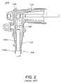
- FIG. 2depicts a conventional elbow connector 200 .
- the names of the two types of connectorsdescribe their shapes.
- Conventional elbow connectors 200 and T-body connectors 100are installed into electric power systems according to similar steps.
- connections described and illustrated herein with respect to a conventional T-body connector 100such as the one shown in FIG. 1
- a conventional elbow connector 200such as the one shown in FIG. 2 .
- a cable 102is inserted into the bottom of a conventional T-body connector 100 .
- the cable 102is first inserted into a cable adapter 104 , which is then inserted into the T-body connector 100 .
- Conventional separable insulated connectorsoften use cable adapters 104 to increase the variety of cables that can be used with the connector.
- Each cable adapter 104can be designed to accept a range of cable widths, each width within the range being sufficiently narrow to fit within the opening provided in the cable adapter 104 and sufficiently wide to be secured within the opening in the cable adapter 104 .
- Each separable insulated connectorcan then be designed to accept a range of cable adapter 104 widths, thereby enabling each separable insulated connector to accept a large range of cable widths.
- Conventional cable adapters 104can include an insulating material 104 a and a semi-conductive material 104 b , as shown in FIGS. 1 and 2 .
- the cable 102connects to the T-body 100 at a compression connector 106 , which crimps the cable 102 , holding it in place and allowing power to transfer from the cable 102 to the T-body 100 .
- the compression connector 106is in turn connected to an output extension 108 within a bushing 110 .
- the bushing 110is connected to a switchgear, transformer, or other energy distribution component.
- Separable insulated connectorssuch as those shown in FIGS. 1 and 2 may need to be removed from the energy distribution system for a variety of reasons.
- One common reasonis that the connectors sometimes fail, for example due to a power surge or a fault with the connection to the cable 102 .
- Another reasonis that the operators of the energy distribution system may want to change the type of switchgear or transformers to which the insulated connectors are connected, which could necessitate a change in the type of separable insulated connector required. Regardless of the reason for removing the separable insulated connectors, such removal and the subsequent replacement with another connector has traditionally been a difficult task.
- the compression connector 106may be used only one time, because it is compressed around the cable 102 .
- the cable 102 inserted into the connectormust be cut at some point along a portion of the cable 102 that was not inserted into the connector before installing a replacement connector. Then, when installing the replacement connector, the cut cable 102 may be too short to reach the compression connector 106 in the replacement connector, which would connect to the switchgear, transformer, or other distribution component.
- spliceshave been used to extend the length of a cut cable to connect the cable to the replacement separable insulated connector, thereby providing sufficient length for the separable insulated connector to maintain a connection with both the cable and the distribution component.
- Splicing a cablefirst requires stripping the insulation on the end of the short cable and connecting it to a first end of a splice. Then, another section of similar cable, which will serve as the extension, must also be cut. Both ends of the extension cable must then be stripped, with one end being inserted into a second end of the splice, and the other end being inserted into the separable insulated connector.
- the task of splicing in an extension cable sufficient in length to reach the replacement connectorrequires three separate stripping and connection steps, each of which can be a labor intensive and error prone process.
- An alternative method of connecting a cable that has been cut to a separable insulated connectoris to use a separable insulated connector with a longer body.
- a separable insulated connectorwith a longer body.
- Such a connectormay be designed to be sufficiently long to reach a cable that a conventional separable insulated connector could not, while still being able to connect to the distribution component.
- manufacturing separable insulated connectors with longer bodies (and varying lengths)requires investing in new molds that would be used to manufacture the connectors with such an increased length. The production, purchase, installation, and use of these molds would thus result in a significant cost.
- a need in the artexists for replacing a separable insulated connector in an electric power system that addresses the disadvantages found in the prior art. Specifically, a need in the art exists for connecting a replacement separable insulated connector to a cable with a short length without the labor intensive and error prone process of splicing an extension to the cable. A need in the art also exists for connecting a cable with a short length to a separable insulated connector that has a body of a standard length, so as not to require the costly investment of new molds and processes for manufacturing separable insulated connectors with longer bodies.
- the inventionprovides an efficient and cost effective method and device for replacing a separable insulated connector in an electric power system, and providing an electric connection between a cable and power distribution components.
- the inventionprovides an extender for a separable insulated connector for connecting a cable that has been cut, or otherwise has a length insufficient to connect to a conventional separable insulated connector, to a power distribution system.
- the inventionaccomplishes this task without requiring either an extension cable to be spliced to the shortened cable or a separable insulated connector with a longer body.
- an extender for a cable adapter for use with a T-body or elbow connectoris an easier task than molding an extended T-body or elbow connector for several reasons.
- an extendermay typically be smaller in size than T-body or elbow connector bodies, and such an extender may therefore be even smaller than an extended T-body or elbow connector body. If the body of the T-body or elbow connector were lengthened, a larger press and mold base would be required.
- an extendermay typically have approximately cylindrical dimensions, as opposed to the shells of T-body or elbow connectors, which typically include additional sides, curves, holes, and angles, further complicating the design of the press and mold needed. Thus, manufacturing an extender may avoid the excessive financial and time investment in manufacturing longer T-body or elbow connectors.
- the inventionprovides an extender for a standard separable insulated connector, such as a T-body connector or an elbow connector with a size and shape associated with conventional T-body and elbow connectors.
- the extendercan extend the effective length of the separable insulated connector, such that the extender can connect to a conventional cable adapter, which in turn connects to a shortened cable.
- the extendercan include the same or similar interfaces for a cable adapter that a separable insulated connector has, and thus, a conventional cable adapter may be connected to the extender in the same manner in which conventional cable adapters can connect to conventional separable insulated connectors.
- the extender's lengthenables it to be connected to a conventional cable adapter, and then inserted into a standard sized T-body or elbow connector, which can then be connected to a switchgear, transformer, or other distribution component. Then, the shortened cable can be connected to the cable adapter. Alternatively, the shortened cable can be connected to the cable adapter before the separable insulated connector is connected to the distribution components.
- the extender for the separable insulated connectormay include a compression connector (or any other type of suitable conductive connector) for accepting the shortened cable that is inserted into the cable adapter, a conductive rod connected to the compression connector for carrying electric power from the shortened cable to the T-body or elbow connector, and layers of semi-conductive material and insulating material.
- a “semi-conductive” materialcan refer to rubber or any other type of material that carries current, and thus can include conductive materials.
- a shortened cablecan be inserted into the cable adapter, which then can be connected to the extender. More particularly, the shortened cable can be inserted such that, once the cable adapter is inserted into the extender, the shortened cable is attached to the compression connector of the extender. Then, the extender, with the cable adapter and shortened cable connected therein, may be inserted into a conventional T-body or elbow connector, which can be connected to energy distribution systems or components thereof, such as switchgears and transformers.
- the compression connector within cable adaptersmay be made of a conductive material.
- the compression connectorshould not touch any insulating material in the cable adapter because the insulating material could be damaged by the current passing through the compression connector. Air gaps between the compression connector and the insulating material could cause corona discharge if not shielded.
- the compression connector of the extendermay be bordered by a layer of semi-conductive material.
- This semi-conductive materialcan contact a semi-conductive insert or faraday cage disposed within the T-body or elbow connector.
- the purpose of a faraday cageis to shield all gaps of air within the mating components (such as the cable/cable adapter and the compression connector) of the separable insulated connector, as these air gaps can cause corona discharge within the connector. This discharge can occur if there is a voltage drop across the air gaps, and the discharge can corrode the rubber materials often used to make the separable insulated connector.
- the faraday cageensures that the various mating components have the same electric potential, and thus prevents corona discharge within the mating components.
- the layer of semi-conductive material in the extendercan act as a faraday cage if it contacts the semi-conductive insert of the separable insulated connector and becomes energized by the semi-conductive insert.
- the semi-conductive materialneed not touch the compression connector disposed within the extender. For example, there may be gaps of air between the compression connector and semi-conductive material.
- the compression connector of the extendermay contact a conductive rod, or any other suitable conductive material, for carrying electric power from the shortened cable to the T-body or elbow connector when the extender is connected to cable adapter and inserted into the T-body or elbow connector.
- the conductive rodmay contact a compression connector within the T-body or elbow connector.
- the compression connector within the T-body or elbow connectormay then contact an output extension, for providing electric power to a switchgear, transformer, or other energy distribution component to which the T-body or elbow connector is connected.
- the T-body or elbow connectormay not include a separate compression connector, in addition to the compression connector of the extender. In such an embodiment, the conductive rod may contact an output extension within the T-body or elbow connector directly.
- FIG. 1is a cross-sectional side view of a conventional T-body connector with a conventional cable adapter disposed therein.
- FIG. 2is a cross-sectional side view of a conventional elbow connector with a conventional cable adapter disposed therein.
- FIG. 3is a cross-sectional side view of a T-body connector with an extender connected to a cable adapter disposed therein, according to an exemplary embodiment.
- FIG. 3is a cross-sectional side view of a T-body connector 300 with an extender 304 connected to a cable adapter 104 disposed therein, according to an exemplary embodiment.
- the cable adapter 104 disposed within the extender 304can be similar or identical to the cable adapters 104 used with conventional T-body connectors 100 .
- the T-body connector 300includes many of the features and components associated with conventional T-body connectors 100 .
- the T-body connector 300includes an upper bushing section 310 .
- the upper bushing section 310 of the T-body connector 300includes a first opening 312 and a second opening 314 .
- the first opening 312can be used to attach the T-body connector 300 to a switchgear, transformer, or other energy distribution component to which the T-body connector 300 may be connected.
- a plug 316 or other similar bushingmay be inserted into the first opening 312 , and then the plug 316 may be inserted into an energy distribution component.
- the second opening 314can be used as an access port to tighten a bolt that holds the plug 316 in the first opening 312 of the connector 300 , to connect another device to the T-body connector 300 , such as a device for measuring the electric flow through the T-body 300 , or to connect the T-body 300 to another energy distribution component.
- the second opening 314 of the T-body 300need not be connected to another device, and a protective cap may cover the second opening 314 .
- the T-body connector 300also includes a shell 318 and a semi-conductive insert 320 , both of which comprise a semi-conductive material.
- the shell 318 and the semi-conductive insert 320can be made from a semi-conductive mixture of ethylene propylene dienemonomer (EPDM) rubber and carbon black.
- the shell 318 of the T-body 300may also include a ground wire tab 322 to which a wire 324 may be attached and grounded.
- the semi-conductive EPDM rubber in the shell 318can provide ground shield continuity for the T-body 300 , thereby providing deadfront safety for the shell 318 .
- the grounded shell 318 of the T-body 300allows for operators to touch the exterior of the T-body connector 300 safely.
- the T-body connector 300may include a capacitive test point 326 .
- the capacitive test point 326may be molded on the shell 318 of the T-body 300 .
- the capacitive test point 326provides a location on which a fault indicating device, or other similar device, can be mounted to determine whether problems or irregularities exist with the electric power passing through the T-body connector 300 .
- a protective cap 327may be placed on the capacitive test point 326 when it is not in use.
- the T-body connector 300also includes a layer of insulating material 328 between the shell 318 and the semi-conductive insert 320 .
- the insulating material 328also can include EPDM rubber.
- EPDM rubber serving as the insulating material 328may not include carbon black or other conductive component, so that it may provide the necessary insulation and not conduct electricity.
- the T-body connector 300 shown in FIG. 3further includes a compression connector 306 that is connected to an output extension 308 .
- the compression connector 306can be similar or identical to the compression connector 106 used in conventional T-body connectors 100 utilizing conventional cable adapters 104 .
- any other suitable conductive connectormay be used in place of the compression connector 306 .
- the compression connector 306can be substantially disposed within an opening in the semi-conductive insert 320 .
- the output extension 308can be disposed within an upper bushing section 310 of the T-body connector 300 .
- the compression connector 306can include a protrusion 306 a that extends from the semi-conductive insert 320 and contacts the output extension 308 .
- the output extension 308can contact the compression connector 306 within the semi-conductive insert 320 .
- the output extension 308can comprise any suitable conductive material. Upon installation of the T-body connector 300 , the output extension 308 is in electric communication with—and can carry electric power to—any switchgear, transformer, or other energy distribution component to which the T-body connector 300 may be connected. As shown in FIG. 3 , in exemplary embodiments, the output extension 308 may contact a semi-conductive plug 316 or other bushing that has been inserted into the upper bushing section 310 of the T-body connector 300 . The semi-conductive bushing or plug 316 then can be connected to the energy distribution component, thereby providing electric communication between the output extension 308 and the distribution component. In exemplary embodiments, as shown in FIG. 3 , the output extension 308 can comprise a threaded connection for connecting to the energy distribution components or the semi-conductive bushing or plug 316 .
- the upper end of the compression connector 306contacts the output extension 308 .
- the lower end of the compression connector 306 disposed within the semi-conductive insert 320can contact a conductive rod 330 or other suitable conductive material that carries electric power from an electric cable 302 connected to the cable adapter 104 and the extender 304 .
- the conductive rod 330can extend through the compression connector 306 and contact the output extension 308 .
- the T-body connector 300may not include an output extension 308 , and instead, the conductive rod 330 can extend into the upper bushing section 310 of the T-body connector 300 .
- the semi-conductive insert 320can provide a shield around the compression connector 306 , thereby preventing electricity passing through the compression connector 306 from damaging the insulating material 328 . As shown in FIG. 3 , the semi-conductive insert 320 may, but need not, contact the compression connector 306 directly, as indicated by the presence of gaps of air between the compression connector 306 and the semi-conductive insert 320 . Rather, the semi-conductive insert 320 needs only to provide semi-conductive material that is disposed between the insulating material 328 and the compression connector 306 , thereby functioning as a faraday cage.
- the extender 304can be inserted into the bottom end of the T-body connector 300 .
- the extender 304may include a conductive rod 330 , such as a copper rod or any other suitable conductive rod or member, for carrying electricity from the shortened cable 302 to the T-body connector 300 .
- the upper end of the rod 330may contact the compression connector 306 disposed within the semi-conductive insert 320 .
- the upper end of the rod 330may comprise a terminal for contacting and connecting to the compression connector 306 .
- the compression connector 306also contacts the output extension 308 of the T-body connector 300 , thereby providing electric communication between the rod 330 and the output extension 308 .
- the T-body connector 300may not include a compression connector 306 , or any other conductive connector, disposed within the shell 318 .
- a conductive rod 330 or other suitable conductive material that carries electric power from the shortened cable 302may contact the output extension 308 directly.
- the rod 330may comprise a terminal for contacting and connecting to the output extension 308 of the T-body connector 300 .
- the extender 304 shown in FIG. 3further includes a conductive cable connector, such as a compression connector 332 .
- the shortened cable 302is inserted into the compression connector 332 , which holds the shortened cable 302 securely, in a manner similar to the compression connector 106 used in conventional T-body connectors 100 , such as the one shown in FIG. 1 .
- the extender 304can include a channel 333 above the compression connector, through which the rod 330 can be inserted. Additionally, the extender 304 can include a support tube 335 within the channel 333 , to help keep the channel 333 open and to help prevent it from collapsing.
- the lower end of the rod 330receives electricity from the compression connector 332 , which receives electricity from the shortened cable 302 .
- the rod 330 and shortened cable 302can be inserted into opposite ends of the conductive compression connector 332 , thereby providing an electric connection between the rod 330 and cable 302 .
- the shortened cable 302may be stripped of a protective and/or semi-conductive sheath 302 b to expose a conductive portion 302 a of the cable 302 , and then the conductive portion 302 a of the shortened cable 302 may be inserted into the cable adapter 104 , such that a portion of the cable 302 extends through an opening at the top of the cable adapter 104 .
- the cable adapter 104can be inserted into the extender 304 , and the cable 302 can be inserted into—or otherwise connected to—the compression connector 332 of the extender 304 .
- the conductive rod (such as the rod 330 ) disposed within the extender 304may include the conductive cable connector (such as the compression connector 332 ).
- the rod 330 disposed within the extender 304may be configured such that a cable 302 may be inserted therein.
- the extender 304can comprise two semi-conductive layers 334 , 336 , as well as an insulating layer 338 .
- the extender 304can comprise an inner semi-conductive layer 336 , an insulating layer 338 , and an outer semi-conductive layer 334 .
- the semi-conductive layers 334 , 336can be made from a mixture comprising EPDM rubber and carbon black or other suitable conductive material. In alternative exemplary embodiments, various other suitable materials can be used for the semi-conductive layers 334 , 336 .
- the inner semi-conductive layer 336may surround or border the rod 330 . Additionally, as with the semi-conductive insert 320 discussed previously and the compression connector 306 disposed therein, the inner semi-conductive layer 336 can provide a shield around the compression connector 332 and the rod 330 , thereby preventing electricity passing through the compression connector 332 and the rod 330 from damaging the insulating material 338 . The inner semi-conductive layer 336 may, but need not, contact the compression connector 332 and the rod 330 directly, as long as it is disposed between the insulating material 338 and the compression connector 332 and the rod 330 .
- the inner semi-conductive layer 336 of the extender 304is configured to contact the semi-conductive insert 320 of the T-body connector upon insertion of the extender 304 into the T-body connector 300 . Electrical contact between the semi-conductive insert 320 and the inner semi-conductive layer 336 provides the necessary shield around the compression connector 332 the rod 330 and the compression connector 332 . In alternative embodiments, the inner semi-conductive layer 336 can contact the conductive rod 330 and/or either of the compression connectors 306 , 332 , whether in addition to or instead of contacting the semi-conductive insert 320 to energize the inner semi-conductive layer 336 so that it can act as a faraday cage.
- the inner semi-conductive layer 336does not make electrical contact with the semi-conductive insert 320 , conductive rod 330 , or the compression connector 306 , then there may be a significant voltage drop between the inner semi-conductive layer 336 and the compression connector 332 or the rod 330 . Such a significant voltage drop could cause damage to the insulating layer 338 and could disturb the electricity flow from the shortened cable 302 through the T-body connector 300 .
- the insulating layer 338 of the extender 304is disposed between the inner semi-conductive layer 336 and the outer semi-conductive layer 334 .
- the insulating layer 338can comprise the same material as the insulating material 328 used in the T-body connector 300 .
- the insulating layer 338can comprise EPDM rubber without carbon black or other conductive material mixed therein.
- the insulating layer 338may comprise various other suitable insulating materials known in the art.
- the outer semi-conductive layer 334 of the extender 304may border or surround the insulating layer 338 .
- the outer semi-conductive layer 334may extend further below the insulating layer 338 and the inner semi-conductive layer 336 .
- the outer semi-conductive layer 334is configured to contact the shell 318 of the T-body connector 300 upon insertion of the extender 304 into the T-body connector 300 . Electrical contact between the shell 318 and the outer semi-conductive layer 334 provides for the outer semi-conductive layer 334 to provide ground shield continuity for the exposed portion of the extender 304 . If the outer semi-conductive layer 334 does not make electrical contact with the shell 318 , then it will not be connected to the ground wire 324 discussed previously.
- the outer semi-conductive layer 334is configured to contact the semi-conductive material 104 b of the cable adapter 104 upon insertion of the cable adapter 104 into the extender 304 . Electrical contact between the shortened cable 302 and the semi-conductive material 104 b of the cable adapter 104 , which in turn is in electric contact with the outer semi-conductive layer 334 , can provide ground shield continuity for the exposed portion of the extender 304 , cable adapter 104 , and the shortened cable 302 . If the outer semi-conductive layer 334 does not make electrical contact with the shortened cable 302 , then the shortened cable 302 may not be connected to the ground wire 324 discussed previously.
- the extender 304can be of approximately cylindrical shape (though, as shown, the diameter of the cylindrical shape can increase and decrease through the body of the extender 304 ) and have an interface into which the cable adapter 104 can be inserted.
- such an extender 304can have an inner diameter (measuring the width of the hole through which the cable adapter 104 is inserted) and an outer diameter (measuring the width of the extender 304 ).
- the inner semi-conductive layer 336can run along the inner diameter, and additionally extend to the outer diameter towards the top of the extender 304 , as shown in FIG. 3 . This geometry and configuration can be helpful to ensure that the inner semi-conductive layer 336 contacts the semi-conductive insert 320 disposed within the shell 318 .
- T-body connector 300with an extender 304 connected to a cable adapter 104 disposed therein will now be described with reference to FIGS. 1 and 3 .
- FIGS. 1 and 3One exemplary use of the T-body connector 300 with an extender 304 connected to a cable adapter 104 disposed therein will now be described with reference to FIGS. 1 and 3 .
- variations of the exemplary steps described hereinare possible.
- the conventional T-body connector 100After an operator of a power distribution system has made a decision to replace a conventional T-body connector 100 connected to a cable 102 via a cable adapter 104 on its lower end and a switchgear, transformer, or other energy distribution component on its upper end, the conventional T-body connector 100 must be removed. To do so, the source of power to the cable 102 may be turned off. Removal of the T-body connector 100 can begin with cutting a portion of the cable 102 , thereby freeing the lower end of the conventional T-body 100 . The upper end of the conventional T-body 100 can be unplugged or otherwise disconnected from the energy distribution component to which it was connected either before or after cutting the cable 102 . In an exemplary embodiment, the conventional T-body connector 100 and cable adapter 104 can be discarded at this point.
- the shortened cable 302may be too short to connect to a replacement conventional T-body connector 100 that will be connected to the energy distribution component. Instead, the shortened cable 302 can be inserted into a replacement cable adapter 104 , which may have approximately the same size and dimensions as the discarded cable adapter 104 . Then, the cable adapter 104 can be inserted into an extender 104 .
- the extender 304 selectedcan have dimensions appropriate for accepting the cable adapter 104 with the shortened cable 302 disposed therein, and for being disposed and held securely within the T-body connector 300 upon insertion.
- the shortened cable 302can be stripped of a portion of insulating material commonly found on such cables 302 , thereby exposing a portion of the conductive part of the cable 302 .
- the exposed portion of the shortened cable 302then can be inserted into the cable adapter 104 such that the cable 302 extends through an opening in the cable adapter 104 and then connects to the compression connector 332 disposed within the extender 304 .
- the compression connector 332can hold the cable 302 securely, and can comprise a conductive material so that it can receive electricity carried by the shortened cable 302 .
- the upper end of the compression connector 332can contact a rod 330 , such as a copper rod or any other suitable conductive rod 330 or structure.
- the compression connector 332 and rod 330can be connected such that once power to the system is turned on and electricity flows through the cable 302 , the electricity carried by the shortened cable 302 and received by the compression connector 332 can be conducted to the rod 330 .
- the extender 304is inserted into the T-body connector 300 .
- the extender 304may be inserted into the T-body connector 300 before the shortened cable 302 is inserted into the cable adapter 104 , and then the cable adapter 104 is inserted into the extender 304 .
- Other variations in the order of these stepsare possible, and will be known to one of ordinary skill in the art having the benefit of the present disclosure.
- the extender 304is inserted into the T-body connector 300 such that the rod 330 of the extender 304 contacts the compression connector 306 disposed within the semi-conductive insert 320 of the T-body connector 300 .
- the compression connector 306is, in turn, in electrical contact with the output extension 308 of the T-body connector 300 .
- the inner semi-conductive layer 336 of the extender 304contacts the semi-conductive insert 320 of the T-body connector 300
- the outer semi-conductive layer 334 of the extender 304contacts the shell 318 of the T-body connector 300 and the semi-conductive material 104 b of the cable adapter 104 .
- These connectionsprovide for a shield around the compression connectors 306 , 332 disposed within the T-body connector 300 and extender 304 , and allow for the exterior of the T-body connector 300 , extender 304 , and cable adapter 104 to be grounded upon proper connection of a ground wire 324 to the ground wire tab 322 .
- the T-body connector 300is then connected to the switchgear, transformer, or other energy distribution component to which the conventional T-body connector 300 had been connected.
- one end of a semi-conductive plug 316 or other bushingmay be inserted into an opening 312 , 314 in the upper bushing section 310 of the T-body connector 300 , and then the other end of the semi-conductive plug 316 may be inserted into the energy distribution component.
- the energy distribution componentshould be in electric communication with the T-body connector 300 , the output extension 308 disposed therein, the compression connector 306 disposed within the semi-conductive insert 320 , the rod 330 , the compression connector 332 disposed within the extender 304 , and the shortened cable 302 .
- the source of power to the shortened cable 302can be turned on, thereby providing electricity from the cable 302 , through the cable adapter 104 , extender 304 and T-body connector 300 , and to the energy distribution component, or in the opposite direction.
- extender 304 described with respect FIG. 3is shown inserted into a T-body connector 300
- extenders utilizing similar principles and technologiescan be inserted into a variety of other separable insulated connectors.
- extenderscan be used with elbow connectors, splices, or other separable insulated connectors.
- separable insulated connectorssimilar to the T-body connector 300 of FIG. 3 , can include a semi-conductive insert or faraday cage and a shell comprising semi-conductive material, insulating material between the semi-conductive insert and the shell, and a compression connector disposed within the semi-conductive insert.
- an extendercan be configured to connect to the separable insulated connector according to the same or similar manner in which the extender 304 is connected to the T-body connector 300 described previously.
- the extendercan comprise an inner semi-conductive layer, an insulating layer, and an outer semi-conductive layer.
- Exemplary extenderscan be configured such that when they are inserted into an elbow connector, splice, or other separable insulated connector, the inner semi-conductive layer can contact the semi-conductive insert, and the outer semi-conductive layer can contact the shell of the separable insulated connector.
- Such exemplary extendersalso can include a conductive rod.
- extenders that can be used with a variety of separable insulated connectorsmay include any other suitable conductive structure for carrying electricity from a cable to the connector. One end of the conductive rod can receive electricity from the cable.
- Such extendersmay further include a variety of conductive connectors, such as a compression connector, which can contact the conductive rod and the cable, thereby providing a connection between them.
- an extender 304that connects to a separable insulated connector on its top side and to a cable adapter 104 on its bottom side
- a first extendercan be inserted into a separable insulated connector, and then instead of a cable adapter being inserted into the first extender, a second extender can be inserted therein. Then, a cable adapter can be inserted into the second extender.
- any number of extendersmay be connected to each other, thereby further increasing the ability of the extender to provide a connection between a separable insulated connector and a shortened cable.
- the top-side of an extender 304can have interfaces identical or similar to the top side of a cable adapter 104
- the bottom side of an extender 304can have interfaces identical or similar to the bottom side of a separable insulated connector such as a T-body connector 300 .
- an extender 304 for a separable insulated connectorsuch as a T-body connector 300 , elbow connector, splice, or any other suitable connector—that can be used with a cable adapter 104 (or other extender 304 ) disposed therein.
- a separable insulated connectorsuch as a T-body connector 300 , elbow connector, splice, or any other suitable connector
- cable adapter 104or other extender 304
Landscapes
- Cable Accessories (AREA)
- Coupling Device And Connection With Printed Circuit (AREA)
Abstract
Description
Claims (38)
Priority Applications (3)
| Application Number | Priority Date | Filing Date | Title |
|---|---|---|---|
| US12/082,717US7878849B2 (en) | 2008-04-11 | 2008-04-11 | Extender for a separable insulated connector |
| PCT/US2009/039658WO2009126574A2 (en) | 2008-04-11 | 2009-04-06 | Extender for a separable insulated connector |
| TW098112084ATW200950216A (en) | 2008-04-11 | 2009-04-10 | Extender for a separable insulated connector |
Applications Claiming Priority (1)
| Application Number | Priority Date | Filing Date | Title |
|---|---|---|---|
| US12/082,717US7878849B2 (en) | 2008-04-11 | 2008-04-11 | Extender for a separable insulated connector |
Publications (2)
| Publication Number | Publication Date |
|---|---|
| US20090258547A1 US20090258547A1 (en) | 2009-10-15 |
| US7878849B2true US7878849B2 (en) | 2011-02-01 |
Family
ID=41162534
Family Applications (1)
| Application Number | Title | Priority Date | Filing Date |
|---|---|---|---|
| US12/082,717ActiveUS7878849B2 (en) | 2008-04-11 | 2008-04-11 | Extender for a separable insulated connector |
Country Status (3)
| Country | Link |
|---|---|
| US (1) | US7878849B2 (en) |
| TW (1) | TW200950216A (en) |
| WO (1) | WO2009126574A2 (en) |
Cited By (10)
| Publication number | Priority date | Publication date | Assignee | Title |
|---|---|---|---|---|
| US20130095705A1 (en)* | 2010-03-11 | 2013-04-18 | Preformed Line Products | Electrical connections for high voltage electrical distribution and/or reticulation |
| US8454376B1 (en) | 2011-11-10 | 2013-06-04 | Thomas & Betts International, Inc. | Electrical connector with sacrificial component |
| US20140008169A1 (en)* | 2011-01-14 | 2014-01-09 | Swcc Showa Cable Systems Co., Ltd. | High voltage device system of railcar and railcar |
| CN104253342A (en)* | 2013-06-28 | 2014-12-31 | 通贝国际有限公司 | Electrical connector having cold shrink component |
| US20150295372A1 (en)* | 2014-04-10 | 2015-10-15 | S&C Electric Company | Adjustable bus bar for power distribution equipment |
| US20160248187A1 (en)* | 2015-02-24 | 2016-08-25 | Thomas & Betts International, Llc | Multi-piece jacket for separable connectors |
| US9742180B2 (en) | 2013-06-26 | 2017-08-22 | 3M Innovative Properties Company | Power cable terminal connection device |
| US20170317478A1 (en)* | 2016-04-28 | 2017-11-02 | Novinium, Inc. | Injection electrical connector |
| US10027071B2 (en)* | 2013-06-26 | 2018-07-17 | 3M Innovative Properties Company | Cable connection device |
| US20240088593A1 (en)* | 2021-02-16 | 2024-03-14 | Nkt Hv Cables Ab | Cable Lug Device and Method For Mounting A Cable Lug Device |
Families Citing this family (14)
| Publication number | Priority date | Publication date | Assignee | Title |
|---|---|---|---|---|
| US7854620B2 (en) | 2007-02-20 | 2010-12-21 | Cooper Technologies Company | Shield housing for a separable connector |
| US7666012B2 (en) | 2007-03-20 | 2010-02-23 | Cooper Technologies Company | Separable loadbreak connector for making or breaking an energized connection in a power distribution network |
| US7661979B2 (en) | 2007-06-01 | 2010-02-16 | Cooper Technologies Company | Jacket sleeve with grippable tabs for a cable connector |
| US7950940B2 (en) | 2008-02-25 | 2011-05-31 | Cooper Technologies Company | Separable connector with reduced surface contact |
| US7905735B2 (en) | 2008-02-25 | 2011-03-15 | Cooper Technologies Company | Push-then-pull operation of a separable connector system |
| CN102386501B (en)* | 2010-09-04 | 2014-05-07 | 王日新 | Shielding type T-shaped capacitance type insulation bus joint |
| CN102820565B (en)* | 2011-12-31 | 2014-09-10 | 中航光电科技股份有限公司 | Mixed-loading connector |
| FR3010248B1 (en)* | 2013-09-05 | 2017-03-31 | Nexans | DEVICE FOR JUNCTION OF HYBRID ELECTRIC TRANSPORT CABLES |
| CN107706877A (en)* | 2016-08-08 | 2018-02-16 | 安徽伊法拉电气有限公司 | A kind of shield type separable cable terminal |
| WO2018093995A1 (en) | 2016-11-21 | 2018-05-24 | Ecolab Usa Inc. | Material supply system with a valve assembly and a base assembly provided with an actuator |
| NZ794405A (en) | 2016-11-21 | 2025-06-27 | Ecolab Usa Inc | Material supply system with valve assembly with improved sealing capabilities |
| EP3720795B1 (en) | 2017-12-04 | 2025-01-29 | Ecolab USA Inc. | Powder material hopper system with offset loading |
| EP3720592B1 (en) | 2017-12-04 | 2022-09-21 | Ecolab USA Inc. | Material wetting system with shroud assembly |
| EP3499246B1 (en)* | 2017-12-18 | 2024-04-17 | 3M Innovative Properties Company | Voltage divider assembly |
Citations (211)
| Publication number | Priority date | Publication date | Assignee | Title |
|---|---|---|---|---|
| GB105227A (en) | 1916-03-31 | 1918-02-14 | Henri De La Valette | Improvements in Electric Couplings. |
| US1903956A (en) | 1931-04-17 | 1933-04-18 | Reyrolle A & Co Ltd | High voltage electric switch gear |
| US2953724A (en) | 1954-05-11 | 1960-09-20 | Hilfiker Hans | Electrical distribution boards |
| US3392363A (en) | 1965-06-10 | 1968-07-09 | Amp Inc | Housing member for electrical connector members |
| US3471669A (en) | 1968-01-16 | 1969-10-07 | Chance Co Ab | Encapsulated switch assembly for underground electric distribution service |
| US3474386A (en) | 1964-02-10 | 1969-10-21 | Edwin A Link | Electrical connector |
| US3509516A (en) | 1968-02-01 | 1970-04-28 | Mc Graw Edison Co | High voltage connector and entrance bushing assembly |
| US3509518A (en) | 1968-03-11 | 1970-04-28 | Mc Graw Edison Co | High voltage cable connectors |
| US3513425A (en) | 1969-05-21 | 1970-05-19 | Gen Electric | Modular electrical conductor termination system |
| US3539972A (en) | 1968-05-21 | 1970-11-10 | Amerace Esna Corp | Electrical connector for high voltage electrical systems |
| US3546535A (en) | 1967-10-10 | 1970-12-08 | Smit Nijmegen Electrotec | Transformers and composite tap changers associated therewith |
| US3576493A (en) | 1969-09-25 | 1971-04-27 | Gen Electric | Molded conductor housing with a molded capacitance tap and method of making same |
| US3594685A (en) | 1969-07-14 | 1971-07-20 | Joslyn Mfg & Supply Co | Electrical coupler |
| US3652975A (en) | 1970-01-09 | 1972-03-28 | Westinghouse Electric Corp | Electrical connector assembly |
| US3654590A (en) | 1969-12-30 | 1972-04-04 | Ameraca Esna Corp | Electrical contact devices for high voltage electrical systems |
| US3663928A (en) | 1970-01-09 | 1972-05-16 | Westinghouse Electric Corp | Electrical bushing assembly |
| US3670287A (en) | 1970-08-17 | 1972-06-13 | Westinghouse Electric Corp | Electrical connector assembly |
| US3678432A (en) | 1971-04-26 | 1972-07-18 | Gen Electric | Vented fuse module for underground power cable system |
| US3720904A (en) | 1971-02-04 | 1973-03-13 | Amp Inc | Self-actuating loadbreak connector |
| US3725846A (en) | 1970-10-30 | 1973-04-03 | Itt | Waterproof high voltage connection apparatus |
| US3740503A (en) | 1972-05-02 | 1973-06-19 | Omron Tateisi Electronics Co | Conducting fluid inertia type switch with linearly movable conductive plunger contact |
| US3740511A (en) | 1971-05-06 | 1973-06-19 | J Westmoreland | Vacuum switch |
| US3798586A (en) | 1972-05-22 | 1974-03-19 | P Huska | Union for connecting electrical conductors |
| US3826860A (en) | 1973-03-08 | 1974-07-30 | Amp Inc | High voltage electrical connector |
| US3845233A (en) | 1973-02-12 | 1974-10-29 | Dielectrics Int Ltd | Pressurized insulant of solid and fluid for a conductor |
| US3860322A (en) | 1972-01-03 | 1975-01-14 | Rte Corp | Sealed electrical connector |
| US3915534A (en) | 1967-08-15 | 1975-10-28 | Joslyn Mfg & Supply Co | Grounded surface distribution apparatus |
| US3924914A (en) | 1970-03-04 | 1975-12-09 | Philip M Banner | Electrical safety grounding device means |
| US3945699A (en) | 1974-09-27 | 1976-03-23 | Kearney-National Inc. | Electric connector apparatus and method |
| US3949343A (en) | 1967-08-15 | 1976-04-06 | Joslyn Mfg. And Supply Co. | Grounded surface distribution apparatus |
| US3953099A (en) | 1973-12-10 | 1976-04-27 | Bunker Ramo Corporation | One-piece environmental removable contact connector |
| US3955874A (en) | 1974-10-29 | 1976-05-11 | General Electric Company | Shielded power cable separable connector module having a conductively coated insulating rod follower |
| US3957332A (en) | 1975-05-02 | 1976-05-18 | Kearney-National, Inc. | Electric connector apparatus and method |
| US3960433A (en) | 1975-09-05 | 1976-06-01 | General Electric Company | Shielded power cable separable connector module having conducting contact rod with a beveled shoulder overlapped by insulating follower material |
| US4029380A (en) | 1967-08-15 | 1977-06-14 | Joslyn Mfg. And Supply Co. | Grounded surface distribution apparatus |
| US4040696A (en) | 1975-04-30 | 1977-08-09 | Matsushita Electric Works, Ltd. | Electric device having rotary current collecting means |
| US4067636A (en) | 1976-08-20 | 1978-01-10 | General Electric Company | Electrical separable connector with stress-graded interface |
| US4088383A (en) | 1976-08-16 | 1978-05-09 | International Telephone And Telegraph Corporation | Fault-closable electrical connector |
| US4103123A (en) | 1977-06-27 | 1978-07-25 | Northwestern Public Service Company | Grounding device |
| US4107486A (en) | 1976-06-30 | 1978-08-15 | S & C Electric Company | Switch operating mechanisms for high voltage switches |
| US4113339A (en) | 1977-08-29 | 1978-09-12 | Westinghouse Electric Corp. | Load break bushing |
| US4123131A (en) | 1977-08-05 | 1978-10-31 | General Motors Corporation | Vented electrical connector |
| US4152643A (en) | 1978-04-10 | 1979-05-01 | E. O. Schweitzer Manufacturing Co., Inc. | Voltage indicating test point cap |
| US4154993A (en) | 1977-09-26 | 1979-05-15 | Mcgraw-Edison Company | Cable connected drawout switchgear |
| US4161012A (en) | 1977-03-02 | 1979-07-10 | Joslyn Mfg. And Supply Co. | High voltage protection apparatus |
| US4163118A (en) | 1977-04-19 | 1979-07-31 | Coq B.V. | Busbar system of electric high-voltage switchgear |
| US4186985A (en) | 1978-08-29 | 1980-02-05 | Amerace Corporation | Electrical connector |
| US4203017A (en) | 1978-07-24 | 1980-05-13 | Integrated Electronics Corporation | Electric switch |
| US4210381A (en) | 1978-08-30 | 1980-07-01 | Amerace Corporation | Electrical connector contacts |
| US4223179A (en) | 1978-01-05 | 1980-09-16 | Joslyn Mfg. And Supply Co. | Cable termination connector assembly |
| US4260214A (en) | 1979-07-23 | 1981-04-07 | International Telephone And Telegraph Corporation | Fault-closable electrical connector |
| US4343356A (en) | 1972-10-06 | 1982-08-10 | Sonics International, Inc. | Method and apparatus for treating subsurface boreholes |
| DE3110609A1 (en) | 1981-03-18 | 1982-10-07 | Siemens Ag | Mechanical-electrical plug connection |
| US4353611A (en) | 1980-03-06 | 1982-10-12 | Amerace Corporation | Bushing well stud construction |
| US4354721A (en) | 1980-12-31 | 1982-10-19 | Amerace Corporation | Attachment arrangement for high voltage electrical connector |
| US4360967A (en) | 1980-12-31 | 1982-11-30 | Amerace Corporation | Assembly tool for electrical connectors |
| US4377547A (en)* | 1982-01-18 | 1983-03-22 | Minnesota Mining And Manufacturing Company | Molded high voltage splice body |
| US4443054A (en) | 1981-06-01 | 1984-04-17 | Kanagawa Prefectual Government | Earth terminal for electrical equipment |
| FR2508729B1 (en) | 1981-06-24 | 1984-10-19 | Lb Air | |
| US4484169A (en) | 1981-11-05 | 1984-11-20 | Mitsubishi Denki Kabushiki Kaisha | Transformer apparatus with -superimposed insulated switch and transformer units |
| US4500935A (en) | 1981-09-02 | 1985-02-19 | Mitsubishi Denki Kabushiki Kaisha | Package substation in tank with separate chambers |
| US4508413A (en) | 1982-04-12 | 1985-04-02 | Allied Corporation | Connector |
| US4568804A (en) | 1983-09-06 | 1986-02-04 | Joslyn Mfg. And Supply Co. | High voltage vacuum type circuit interrupter |
| US4600260A (en) | 1981-12-28 | 1986-07-15 | Amerace Corporation | Electrical connector |
| US4626755A (en) | 1984-12-14 | 1986-12-02 | General Electric Company | Sump pump motor switch circuit |
| US4638403A (en) | 1983-06-15 | 1987-01-20 | Hitachi, Ltd. | Gas-insulated switchgear apparatus |
| DE3521365C1 (en) | 1985-06-14 | 1987-02-19 | Stocko Metallwarenfab Henkels | Electrical plug connection |
| US4688013A (en) | 1985-05-09 | 1987-08-18 | Mitsubishi Denki Kabushiki Kaisha | Switchgear assembly for electrical apparatus |
| JPS62198677A (en) | 1986-02-26 | 1987-09-02 | Nissan Chem Ind Ltd | Tetraol derivative |
| US4700258A (en) | 1986-07-21 | 1987-10-13 | Colt Industries Inc. | Lightning arrester system for underground loop distribution circuit |
| US4715104A (en) | 1986-09-18 | 1987-12-29 | Rte Corporation | Installation tool |
| US4722694A (en) | 1986-12-01 | 1988-02-02 | Rte Corporation | High voltage cable connector |
| JPS6393081U (en) | 1986-12-05 | 1988-06-16 | ||
| US4767894A (en) | 1984-12-22 | 1988-08-30 | Bp Chemicals Limited | Laminated insulated cable having strippable layers |
| US4767941A (en) | 1985-11-14 | 1988-08-30 | Bbc Brown, Boveri & Co., Ltd. | Method for error-protected actuation of the switching devices of a switching station and an apparatus thereof |
| US4779341A (en) | 1987-10-13 | 1988-10-25 | Rte Corporation | Method of using a tap plug installation tool |
| US4793637A (en) | 1987-09-14 | 1988-12-27 | Aeroquip Corporation | Tube connector with indicator and release |
| US4799895A (en) | 1987-06-22 | 1989-01-24 | Amerace Corporation | 600-Amp hot stick operable screw-assembled connector system |
| US4820183A (en) | 1986-09-12 | 1989-04-11 | Cooper Industries | Connection mechanism for connecting a cable connector to a bushing |
| US4822291A (en) | 1986-03-20 | 1989-04-18 | Joslyn Corporation | Gas operated electrical connector |
| US4834677A (en) | 1987-04-10 | 1989-05-30 | Baxter Travenol Laboratories, Inc. | Male and/or female electrical connectors |
| US4857021A (en) | 1988-10-17 | 1989-08-15 | Cooper Power Systems, Inc. | Electrical connector assembly and method for connecting the same |
| US4863392A (en) | 1988-10-07 | 1989-09-05 | Amerace Corporation | High-voltage loadbreak bushing insert connector |
| US4867687A (en) | 1988-06-29 | 1989-09-19 | Houston Industries Incorporated | Electrical elbow connection |
| US4871888A (en) | 1988-02-16 | 1989-10-03 | Bestel Ernest F | Tubular supported axial magnetic field interrupter |
| US4891016A (en) | 1989-03-29 | 1990-01-02 | Amerace Corporation | 600-Amp hot stick-operable pin-and-socket assembled connector system |
| US4911655A (en) | 1988-09-19 | 1990-03-27 | Raychem Corporation | Wire connect and disconnect indicator |
| US4946393A (en) | 1989-08-04 | 1990-08-07 | Amerace Corporation | Separable connector access port and fittings |
| US4955823A (en) | 1989-10-10 | 1990-09-11 | Amerace Corporation | 600-Amp hot stick-operable screw and pin-and-socket assembled connector system |
| US4972049A (en) | 1987-12-11 | 1990-11-20 | Cooper Power Systems, Inc. | Bushing and gasket assembly |
| US4982059A (en) | 1990-01-02 | 1991-01-01 | Cooper Industries, Inc. | Axial magnetic field interrupter |
| US5025121A (en) | 1988-12-19 | 1991-06-18 | Siemens Energy & Automation, Inc. | Circuit breaker contact assembly |
| US5045656A (en) | 1989-07-05 | 1991-09-03 | Idec Izumi Corporation | Switch provided with indicator |
| US5045968A (en) | 1988-03-11 | 1991-09-03 | Hitachi, Ltd. | Gas insulated switchgear with bus-section-unit circuit breaker and disconnect switches connected to external lead-out means connectable to other gas insulated switchgear |
| US5114357A (en)* | 1991-04-29 | 1992-05-19 | Amerace Corporation | High voltage elbow |
| US5128824A (en) | 1991-02-20 | 1992-07-07 | Amerace Corporation | Directionally vented underground distribution surge arrester |
| US5130495A (en) | 1991-01-24 | 1992-07-14 | G & W Electric Company | Cable terminator |
| GB2254493A (en) | 1990-12-27 | 1992-10-07 | Rover Group | A connector for a high tension lead. |
| US5175403A (en) | 1991-08-22 | 1992-12-29 | Cooper Power Systems, Inc. | Recloser means for reclosing interrupted high voltage electric circuit means |
| US5213517A (en) | 1992-02-10 | 1993-05-25 | G & H Technology, Inc. | Separable electrodes with electric arc quenching means |
| US5221220A (en) | 1992-04-09 | 1993-06-22 | Cooper Power Systems, Inc. | Standoff bushing assembly |
| US5230640A (en)* | 1991-03-12 | 1993-07-27 | Cables Pirelli | Connecting device for one or two electric cables, and process for mounting this device on the end of the cable or cables |
| US5230142A (en) | 1992-03-20 | 1993-07-27 | Cooper Power Systems, Inc. | Operating and torque tool |
| US5248263A (en) | 1990-11-22 | 1993-09-28 | Yazaki Corporation | Watertight electric connector |
| US5266041A (en) | 1992-01-24 | 1993-11-30 | Luca Carlo B De | Loadswitching bushing connector for high power electrical systems |
| US5277605A (en) | 1992-09-10 | 1994-01-11 | Cooper Power Systems, Inc. | Electrical connector |
| US5356304A (en) | 1993-09-27 | 1994-10-18 | Molex Incorporated | Sealed connector |
| US5359163A (en) | 1993-04-28 | 1994-10-25 | Eaton Corporation | Pushbutton switch with adjustable pretravel |
| US5358420A (en) | 1993-06-07 | 1994-10-25 | Ford Motor Company | Pressure relief for an electrical connector |
| US5393240A (en) | 1993-05-28 | 1995-02-28 | Cooper Industries, Inc. | Separable loadbreak connector |
| US5427538A (en) | 1993-09-22 | 1995-06-27 | Cooper Industries, Inc. | Electrical connecting system |
| US5429519A (en) | 1992-09-03 | 1995-07-04 | Sumitomo Wiring Systems, Ltd. | Connector examining device |
| US5433622A (en) | 1994-07-07 | 1995-07-18 | Galambos; Louis G. | High voltage connector |
| US5435747A (en) | 1991-02-25 | 1995-07-25 | N.V. Raychem S.A. | Electrically-protected connector |
| US5468164A (en) | 1993-08-20 | 1995-11-21 | Gec Alsthom T & D, Inc. | Female contact, in particular for a high tension section switch |
| US5492487A (en) | 1993-06-07 | 1996-02-20 | Ford Motor Company | Seal retention for an electrical connector assembly |
| US5573410A (en)* | 1995-03-02 | 1996-11-12 | Amerace Corporation | Variable size entry insert for cable accessories and method |
| US5589671A (en) | 1995-08-22 | 1996-12-31 | Us Controls Corp. | Rotary switch with spring stabilized contact control rotor |
| EP0624940B1 (en) | 1993-05-14 | 1997-03-26 | Legrand | Trunking with a cover joint device equipped with a fastener, especially for electrical apparatus |
| US5619021A (en) | 1993-11-19 | 1997-04-08 | Sumitomo Wiring Systems, Ltd. | Lever switch device, method for activating switches in a lever switch device, and method for outputting data signals |
| US5641310A (en) | 1994-12-08 | 1997-06-24 | Hubbell Incorporated | Locking type electrical connector with retention feature |
| EP0782162A2 (en) | 1995-12-26 | 1997-07-02 | Amerace Corporation | High voltage switches |
| US5655921A (en) | 1995-06-07 | 1997-08-12 | Cooper Industries, Inc. | Loadbreak separable connector |
| US5661280A (en) | 1995-08-02 | 1997-08-26 | Abb Power T&D Company Inc. | Combination of a gas-filled interrupter and oil-filled transformer |
| US5667060A (en) | 1995-12-26 | 1997-09-16 | Amerace Corporation | Diaphragm seal for a high voltage switch environment |
| US5717185A (en) | 1995-12-26 | 1998-02-10 | Amerace Corporation | Operating mechanism for high voltage switch |
| US5736705A (en) | 1996-09-13 | 1998-04-07 | Cooper Industries, Inc. | Grading ring insert assembly |
| US5737874A (en) | 1994-12-15 | 1998-04-14 | Simon Roofing And Sheet Metal Corp. | Shutter construction and method of assembly |
| US5747765A (en) | 1996-09-13 | 1998-05-05 | Cooper Industries, Inc. | Vertical antitracking skirts |
| US5747766A (en) | 1993-03-16 | 1998-05-05 | Cooper Industries, Inc. | Operating mechanism usable with a vacuum interrupter |
| US5766030A (en) | 1995-12-25 | 1998-06-16 | Yazaki Corporation | Cap type connector assembly for high-voltage cable |
| US5766517A (en) | 1995-12-21 | 1998-06-16 | Cooper Industries, Inc. | Dielectric fluid for use in power distribution equipment |
| US5788535A (en)* | 1996-09-11 | 1998-08-04 | Augat/Lrc Electronics, Inc. | Adaptor assembly |
| US5795180A (en) | 1996-12-04 | 1998-08-18 | Amerace Corporation | Elbow seating indicator |
| US5816835A (en) | 1996-10-21 | 1998-10-06 | Alden Products Company | Multi-sleeve high-voltage cable plug with vented seal |
| US5846093A (en) | 1997-05-21 | 1998-12-08 | Cooper Industries, Inc. | Separable connector with a reinforcing member |
| US5857862A (en) | 1997-03-04 | 1999-01-12 | Cooper Industries, Inc. | Loadbreak separable connector |
| JPH1175181A (en) | 1998-07-07 | 1999-03-16 | Sony Corp | Converter and conversion method for digital image signal |
| US5912604A (en) | 1997-02-04 | 1999-06-15 | Abb Power T&D Company, Inc. | Molded pole automatic circuit recloser with bistable electromagnetic actuator |
| US5917167A (en) | 1996-09-13 | 1999-06-29 | Cooper Industries, Inc. | Encapsulated vacuum interrupter and method of making same |
| US5936825A (en) | 1998-03-18 | 1999-08-10 | Copper Industries, Inc. | Rise pole termination/arrestor combination |
| US5957712A (en) | 1997-07-30 | 1999-09-28 | Thomas & Betts International, Inc. | Loadbreak connector assembly which prevents switching flashover |
| EP0957496A2 (en) | 1998-05-11 | 1999-11-17 | ABB Trasformatori S.p.A. | Power and/or distribution transformer equipped with on-load tap-changer |
| US6022247A (en) | 1996-12-10 | 2000-02-08 | Yazaki Corporation | Electric wiring block |
| US6040538A (en) | 1996-05-24 | 2000-03-21 | S&C Electric Company | Switchgear assembly |
| US6042407A (en)* | 1998-04-23 | 2000-03-28 | Hubbell Incorporated | Safe-operating load reducing tap plug and method using the same |
| DE19906972A1 (en) | 1999-02-19 | 2000-08-24 | Abb Patent Gmbh | Vacuum switch chamber has cylindrical insulating ring between housing and vacuum chamber and compressed so elastic material is pressed against internal housing and external chamber surfaces |
| US6130394A (en) | 1996-08-26 | 2000-10-10 | Elektrotechnische Weke Fritz Driescher & Sohne GmbH | Hermetically sealed vacuum load interrupter switch with flashover features |
| US6168447B1 (en) | 1997-07-30 | 2001-01-02 | Thomas & Betts International, Inc. | Loadbreak connector assembly which prevents switching flashover |
| US6213799B1 (en) | 1998-05-27 | 2001-04-10 | Hubbell Incorporated | Anti-flashover ring for a bushing insert |
| US6220888B1 (en) | 1999-06-25 | 2001-04-24 | Hubbell Incorporated | Quick disconnect cable connector device with integral body and strain relief structure |
| US6227908B1 (en) | 1996-07-26 | 2001-05-08 | Wolfram Aumeier | Electric connection |
| US6250950B1 (en) | 1998-11-25 | 2001-06-26 | Supplie & Co. Import/Export, Inc. | Screwless terminal block |
| US20010008810A1 (en) | 1999-05-25 | 2001-07-19 | George David Daniel | Electrical signal coupling device |
| US6280659B1 (en) | 1996-03-01 | 2001-08-28 | David W. Sundin | Vegetable seed oil insulating fluid |
| US6332785B1 (en) | 1997-06-30 | 2001-12-25 | Cooper Industries, Inc. | High voltage electrical connector with access cavity and inserts for use therewith |
| US6362445B1 (en) | 2000-01-03 | 2002-03-26 | Eaton Corporation | Modular, miniaturized switchgear |
| US6364216B1 (en) | 2001-02-20 | 2002-04-02 | G&W Electric Co. | Universal power connector for joining flexible cables to rigid devices in any of many configurations |
| US6416338B1 (en) | 2001-03-13 | 2002-07-09 | Hubbell Incorporated | Electrical connector with dual action piston |
| US6504103B1 (en) | 1993-03-19 | 2003-01-07 | Cooper Industries, Inc. | Visual latching indicator arrangement for an electrical bushing and terminator |
| US6517366B2 (en) | 2000-12-06 | 2003-02-11 | Utilx Corporation | Method and apparatus for blocking pathways between a power cable and the environment |
| US6520795B1 (en) | 2001-08-02 | 2003-02-18 | Hubbell Incorporated | Load reducing electrical device |
| US6538312B1 (en) | 2000-05-16 | 2003-03-25 | Sandia Corporation | Multilayered microelectronic device package with an integral window |
| US6542056B2 (en) | 2001-04-30 | 2003-04-01 | Eaton Corporation | Circuit breaker having a movable and illuminable arc fault indicator |
| US6566996B1 (en) | 1999-09-24 | 2003-05-20 | Cooper Technologies | Fuse state indicator |
| US20030114045A1 (en)* | 1997-08-02 | 2003-06-19 | Montena Noah P. | Connector and method of operation |
| US6648683B2 (en)* | 2001-05-03 | 2003-11-18 | Timothy L. Youtsey | Quick connector for a coaxial cable |
| US20030228779A1 (en) | 2002-05-16 | 2003-12-11 | Homac Mfg. Company | Electrical connector including cold shrink core and thermoplastic elastomer material and associated methods |
| US6689947B2 (en) | 1998-05-15 | 2004-02-10 | Lester Frank Ludwig | Real-time floor controller for control of music, signal processing, mixing, video, lighting, and other systems |
| US6705898B2 (en) | 2000-11-07 | 2004-03-16 | Endress + Hauser Conducta Gesellschaft Fur Mess-Und Regeltechnik Mbh +Co. | Connector for connecting a transmission line to at least one sensor |
| US6709294B1 (en) | 2002-12-17 | 2004-03-23 | Teradyne, Inc. | Electrical connector with conductive plastic features |
| US6733322B2 (en) | 2000-09-01 | 2004-05-11 | Tyco Electronics Amp Gmbh | Pluggable connection housing with anti-kink element |
| US6744255B1 (en) | 2002-10-30 | 2004-06-01 | Mcgraw -Edison Company | Grounding device for electric power distribution systems |
| US20040121657A1 (en) | 2002-12-23 | 2004-06-24 | Frank Muench | Switchgear using modular push-on deadfront bus bar system |
| US6790063B2 (en) | 2002-05-16 | 2004-09-14 | Homac Mfg. Company | Electrical connector including split shield monitor point and associated methods |
| US6809413B1 (en) | 2000-05-16 | 2004-10-26 | Sandia Corporation | Microelectronic device package with an integral window mounted in a recessed lip |
| US6811418B2 (en) | 2002-05-16 | 2004-11-02 | Homac Mfg. Company | Electrical connector with anti-flashover configuration and associated methods |
| US6830475B2 (en) | 2002-05-16 | 2004-12-14 | Homac Mfg. Company | Electrical connector with visual seating indicator and associated methods |
| US6843685B1 (en) | 2003-12-24 | 2005-01-18 | Thomas & Betts International, Inc. | Electrical connector with voltage detection point insulation shield |
| US6905356B2 (en) | 2002-05-16 | 2005-06-14 | Homac Mfg. Company | Electrical connector including thermoplastic elastomer material and associated methods |
| US6936947B1 (en) | 1996-05-29 | 2005-08-30 | Abb Ab | Turbo generator plant with a high voltage electric generator |
| US6939151B2 (en) | 1997-07-30 | 2005-09-06 | Thomas & Betts International, Inc. | Loadbreak connector assembly which prevents switching flashover |
| US20050208808A1 (en) | 2002-05-16 | 2005-09-22 | Homac Mfg. Company | Electrical connector including silicone elastomeric material and associated methods |
| US20050212629A1 (en) | 2004-03-29 | 2005-09-29 | General Electric Company | Circuit breaker configured to be remotely operated |
| US20050260876A1 (en) | 2004-05-20 | 2005-11-24 | Hubbell Incorporated | Electrical connector having a piston-contact element |
| US6984791B1 (en) | 1993-03-19 | 2006-01-10 | Cooper Technologies Company | Visual latching indicator arrangement for an electrical bushing and terminator |
| US20060051499A1 (en)* | 2002-12-23 | 2006-03-09 | Luca Balconi | Method for producing a coating layer made of expandable and cross-linkable material in a cable |
| US7018236B2 (en) | 2003-11-21 | 2006-03-28 | Mitsumi Electric Co., Ltd. | Connector with resin molded portion |
| US7044769B2 (en) | 2003-11-26 | 2006-05-16 | Hubbell Incorporated | Electrical connector with seating indicator |
| US7044760B2 (en) | 1997-07-30 | 2006-05-16 | Thomas & Betts International, Inc. | Separable electrical connector assembly |
| US7050278B2 (en) | 2002-05-22 | 2006-05-23 | Danfoss Drives A/S | Motor controller incorporating an electronic circuit for protection against inrush currents |
| US20060110983A1 (en) | 2004-11-24 | 2006-05-25 | Muench Frank J | Visible power connection |
| US7079367B1 (en) | 1999-11-04 | 2006-07-18 | Abb Technology Ag | Electric plant and method and use in connection with such plant |
| US20060160388A1 (en) | 2005-01-14 | 2006-07-20 | Hughes David C | Electrical connector assembly |
| US7083450B1 (en) | 2005-06-07 | 2006-08-01 | Cooper Technologies Company | Electrical connector that inhibits flashover |
| US7104823B2 (en) | 2002-05-16 | 2006-09-12 | Homac Mfg. Company | Enhanced separable connector with thermoplastic member and related methods |
| US7108568B2 (en) | 2004-08-11 | 2006-09-19 | Homac Mfg. Company | Loadbreak electrical connector probe with enhanced threading and related methods |
| US20060216992A1 (en) | 2005-03-25 | 2006-09-28 | Hughes David C | Over-voltage protection system |
| US7134889B2 (en) | 2005-01-04 | 2006-11-14 | Cooper Technologies Company | Separable insulated connector and method |
| US7150098B2 (en) | 2003-12-24 | 2006-12-19 | Thomas & Betts International, Inc. | Method for forming an electrical connector with voltage detection point insulation shield |
| US7170004B2 (en) | 2002-02-18 | 2007-01-30 | Abb Schweiz Ag | Surrounding body for a high voltage cable and cable element, which is provided with such a surrounding body |
| US7168983B2 (en) | 2004-08-06 | 2007-01-30 | Tyco Electronics Raychem Gmbh | High voltage connector arrangement |
| US20070026714A1 (en) | 2005-07-28 | 2007-02-01 | Cooper Technologies Company | Electrical connector |
| US20070026713A1 (en) | 2005-07-29 | 2007-02-01 | Hughes David C | Separable loadbreak connector and system with shock absorbent fault closure stop |
| US20070032110A1 (en) | 2005-08-08 | 2007-02-08 | Hughes David C | Apparatus, system and methods for deadfront visible loadbreak |
| US20070097601A1 (en) | 2005-07-11 | 2007-05-03 | Hughes David C | Combination electrical connector |
| US20070108164A1 (en) | 2005-11-14 | 2007-05-17 | Muench Frank J | Vacuum switchgear assembly, system and method |
| US7247266B2 (en) | 2002-04-10 | 2007-07-24 | Thomas & Betts International Inc. | Lubricating coating and application process for elastomeric electrical cable accessories |
| US7247061B2 (en) | 2005-06-30 | 2007-07-24 | Tyco Electronics Corporation | Connector assembly for conductors of a utility power distribution system |
| US7258585B2 (en) | 2005-01-13 | 2007-08-21 | Cooper Technologies Company | Device and method for latching separable insulated connectors |
| US7591693B2 (en) | 2005-01-13 | 2009-09-22 | Cooper Technologies Company | Device and method for latching separable insulated connectors |
- 2008
- 2008-04-11USUS12/082,717patent/US7878849B2/enactiveActive
- 2009
- 2009-04-06WOPCT/US2009/039658patent/WO2009126574A2/enactiveApplication Filing
- 2009-04-10TWTW098112084Apatent/TW200950216A/enunknown
Patent Citations (229)
| Publication number | Priority date | Publication date | Assignee | Title |
|---|---|---|---|---|
| GB105227A (en) | 1916-03-31 | 1918-02-14 | Henri De La Valette | Improvements in Electric Couplings. |
| US1903956A (en) | 1931-04-17 | 1933-04-18 | Reyrolle A & Co Ltd | High voltage electric switch gear |
| US2953724A (en) | 1954-05-11 | 1960-09-20 | Hilfiker Hans | Electrical distribution boards |
| US3474386A (en) | 1964-02-10 | 1969-10-21 | Edwin A Link | Electrical connector |
| US3392363A (en) | 1965-06-10 | 1968-07-09 | Amp Inc | Housing member for electrical connector members |
| US4029380A (en) | 1967-08-15 | 1977-06-14 | Joslyn Mfg. And Supply Co. | Grounded surface distribution apparatus |
| US3949343A (en) | 1967-08-15 | 1976-04-06 | Joslyn Mfg. And Supply Co. | Grounded surface distribution apparatus |
| US3915534A (en) | 1967-08-15 | 1975-10-28 | Joslyn Mfg & Supply Co | Grounded surface distribution apparatus |
| US3546535A (en) | 1967-10-10 | 1970-12-08 | Smit Nijmegen Electrotec | Transformers and composite tap changers associated therewith |
| US3471669A (en) | 1968-01-16 | 1969-10-07 | Chance Co Ab | Encapsulated switch assembly for underground electric distribution service |
| US3509516A (en) | 1968-02-01 | 1970-04-28 | Mc Graw Edison Co | High voltage connector and entrance bushing assembly |
| US3509518A (en) | 1968-03-11 | 1970-04-28 | Mc Graw Edison Co | High voltage cable connectors |
| US3539972A (en) | 1968-05-21 | 1970-11-10 | Amerace Esna Corp | Electrical connector for high voltage electrical systems |
| US3513425A (en) | 1969-05-21 | 1970-05-19 | Gen Electric | Modular electrical conductor termination system |
| US3594685A (en) | 1969-07-14 | 1971-07-20 | Joslyn Mfg & Supply Co | Electrical coupler |
| US3576493A (en) | 1969-09-25 | 1971-04-27 | Gen Electric | Molded conductor housing with a molded capacitance tap and method of making same |
| US3654590A (en) | 1969-12-30 | 1972-04-04 | Ameraca Esna Corp | Electrical contact devices for high voltage electrical systems |
| US3663928A (en) | 1970-01-09 | 1972-05-16 | Westinghouse Electric Corp | Electrical bushing assembly |
| US3652975A (en) | 1970-01-09 | 1972-03-28 | Westinghouse Electric Corp | Electrical connector assembly |
| US3924914A (en) | 1970-03-04 | 1975-12-09 | Philip M Banner | Electrical safety grounding device means |
| US3670287A (en) | 1970-08-17 | 1972-06-13 | Westinghouse Electric Corp | Electrical connector assembly |
| US3725846A (en) | 1970-10-30 | 1973-04-03 | Itt | Waterproof high voltage connection apparatus |
| US3720904A (en) | 1971-02-04 | 1973-03-13 | Amp Inc | Self-actuating loadbreak connector |
| US3678432A (en) | 1971-04-26 | 1972-07-18 | Gen Electric | Vented fuse module for underground power cable system |
| US3740511A (en) | 1971-05-06 | 1973-06-19 | J Westmoreland | Vacuum switch |
| US3860322A (en) | 1972-01-03 | 1975-01-14 | Rte Corp | Sealed electrical connector |
| US3740503A (en) | 1972-05-02 | 1973-06-19 | Omron Tateisi Electronics Co | Conducting fluid inertia type switch with linearly movable conductive plunger contact |
| US3798586A (en) | 1972-05-22 | 1974-03-19 | P Huska | Union for connecting electrical conductors |
| US4343356A (en) | 1972-10-06 | 1982-08-10 | Sonics International, Inc. | Method and apparatus for treating subsurface boreholes |
| US3845233A (en) | 1973-02-12 | 1974-10-29 | Dielectrics Int Ltd | Pressurized insulant of solid and fluid for a conductor |
| US3826860A (en) | 1973-03-08 | 1974-07-30 | Amp Inc | High voltage electrical connector |
| US3953099A (en) | 1973-12-10 | 1976-04-27 | Bunker Ramo Corporation | One-piece environmental removable contact connector |
| US3945699A (en) | 1974-09-27 | 1976-03-23 | Kearney-National Inc. | Electric connector apparatus and method |
| US3955874A (en) | 1974-10-29 | 1976-05-11 | General Electric Company | Shielded power cable separable connector module having a conductively coated insulating rod follower |
| US4040696A (en) | 1975-04-30 | 1977-08-09 | Matsushita Electric Works, Ltd. | Electric device having rotary current collecting means |
| US3957332A (en) | 1975-05-02 | 1976-05-18 | Kearney-National, Inc. | Electric connector apparatus and method |
| US3960433A (en) | 1975-09-05 | 1976-06-01 | General Electric Company | Shielded power cable separable connector module having conducting contact rod with a beveled shoulder overlapped by insulating follower material |
| US4107486A (en) | 1976-06-30 | 1978-08-15 | S & C Electric Company | Switch operating mechanisms for high voltage switches |
| US4088383A (en) | 1976-08-16 | 1978-05-09 | International Telephone And Telegraph Corporation | Fault-closable electrical connector |
| US4067636A (en) | 1976-08-20 | 1978-01-10 | General Electric Company | Electrical separable connector with stress-graded interface |
| US4161012A (en) | 1977-03-02 | 1979-07-10 | Joslyn Mfg. And Supply Co. | High voltage protection apparatus |
| US4163118A (en) | 1977-04-19 | 1979-07-31 | Coq B.V. | Busbar system of electric high-voltage switchgear |
| US4103123A (en) | 1977-06-27 | 1978-07-25 | Northwestern Public Service Company | Grounding device |
| US4123131A (en) | 1977-08-05 | 1978-10-31 | General Motors Corporation | Vented electrical connector |
| US4113339A (en) | 1977-08-29 | 1978-09-12 | Westinghouse Electric Corp. | Load break bushing |
| US4154993A (en) | 1977-09-26 | 1979-05-15 | Mcgraw-Edison Company | Cable connected drawout switchgear |
| US4223179A (en) | 1978-01-05 | 1980-09-16 | Joslyn Mfg. And Supply Co. | Cable termination connector assembly |
| US4152643A (en) | 1978-04-10 | 1979-05-01 | E. O. Schweitzer Manufacturing Co., Inc. | Voltage indicating test point cap |
| US4203017A (en) | 1978-07-24 | 1980-05-13 | Integrated Electronics Corporation | Electric switch |
| US4186985A (en) | 1978-08-29 | 1980-02-05 | Amerace Corporation | Electrical connector |
| US4210381A (en) | 1978-08-30 | 1980-07-01 | Amerace Corporation | Electrical connector contacts |
| US4260214A (en) | 1979-07-23 | 1981-04-07 | International Telephone And Telegraph Corporation | Fault-closable electrical connector |
| US4353611A (en) | 1980-03-06 | 1982-10-12 | Amerace Corporation | Bushing well stud construction |
| US4354721A (en) | 1980-12-31 | 1982-10-19 | Amerace Corporation | Attachment arrangement for high voltage electrical connector |
| US4360967A (en) | 1980-12-31 | 1982-11-30 | Amerace Corporation | Assembly tool for electrical connectors |
| DE3110609A1 (en) | 1981-03-18 | 1982-10-07 | Siemens Ag | Mechanical-electrical plug connection |
| US4443054A (en) | 1981-06-01 | 1984-04-17 | Kanagawa Prefectual Government | Earth terminal for electrical equipment |
| FR2508729B1 (en) | 1981-06-24 | 1984-10-19 | Lb Air | |
| US4500935A (en) | 1981-09-02 | 1985-02-19 | Mitsubishi Denki Kabushiki Kaisha | Package substation in tank with separate chambers |
| US4484169A (en) | 1981-11-05 | 1984-11-20 | Mitsubishi Denki Kabushiki Kaisha | Transformer apparatus with -superimposed insulated switch and transformer units |
| US4600260A (en) | 1981-12-28 | 1986-07-15 | Amerace Corporation | Electrical connector |
| US4377547A (en)* | 1982-01-18 | 1983-03-22 | Minnesota Mining And Manufacturing Company | Molded high voltage splice body |
| US4508413A (en) | 1982-04-12 | 1985-04-02 | Allied Corporation | Connector |
| US4638403A (en) | 1983-06-15 | 1987-01-20 | Hitachi, Ltd. | Gas-insulated switchgear apparatus |
| US4568804A (en) | 1983-09-06 | 1986-02-04 | Joslyn Mfg. And Supply Co. | High voltage vacuum type circuit interrupter |
| US4626755A (en) | 1984-12-14 | 1986-12-02 | General Electric Company | Sump pump motor switch circuit |
| US4767894A (en) | 1984-12-22 | 1988-08-30 | Bp Chemicals Limited | Laminated insulated cable having strippable layers |
| US4688013A (en) | 1985-05-09 | 1987-08-18 | Mitsubishi Denki Kabushiki Kaisha | Switchgear assembly for electrical apparatus |
| DE3521365C1 (en) | 1985-06-14 | 1987-02-19 | Stocko Metallwarenfab Henkels | Electrical plug connection |
| US4767941A (en) | 1985-11-14 | 1988-08-30 | Bbc Brown, Boveri & Co., Ltd. | Method for error-protected actuation of the switching devices of a switching station and an apparatus thereof |
| JPS62198677A (en) | 1986-02-26 | 1987-09-02 | Nissan Chem Ind Ltd | Tetraol derivative |
| US4822291A (en) | 1986-03-20 | 1989-04-18 | Joslyn Corporation | Gas operated electrical connector |
| US4700258A (en) | 1986-07-21 | 1987-10-13 | Colt Industries Inc. | Lightning arrester system for underground loop distribution circuit |
| US4820183A (en) | 1986-09-12 | 1989-04-11 | Cooper Industries | Connection mechanism for connecting a cable connector to a bushing |
| US4715104A (en) | 1986-09-18 | 1987-12-29 | Rte Corporation | Installation tool |
| US4722694A (en) | 1986-12-01 | 1988-02-02 | Rte Corporation | High voltage cable connector |
| JPS6393081U (en) | 1986-12-05 | 1988-06-16 | ||
| US4834677A (en) | 1987-04-10 | 1989-05-30 | Baxter Travenol Laboratories, Inc. | Male and/or female electrical connectors |
| US4799895A (en) | 1987-06-22 | 1989-01-24 | Amerace Corporation | 600-Amp hot stick operable screw-assembled connector system |
| US4793637A (en) | 1987-09-14 | 1988-12-27 | Aeroquip Corporation | Tube connector with indicator and release |
| US4779341A (en) | 1987-10-13 | 1988-10-25 | Rte Corporation | Method of using a tap plug installation tool |
| US4972049A (en) | 1987-12-11 | 1990-11-20 | Cooper Power Systems, Inc. | Bushing and gasket assembly |
| US4871888A (en) | 1988-02-16 | 1989-10-03 | Bestel Ernest F | Tubular supported axial magnetic field interrupter |
| US5045968A (en) | 1988-03-11 | 1991-09-03 | Hitachi, Ltd. | Gas insulated switchgear with bus-section-unit circuit breaker and disconnect switches connected to external lead-out means connectable to other gas insulated switchgear |
| US4867687A (en) | 1988-06-29 | 1989-09-19 | Houston Industries Incorporated | Electrical elbow connection |
| US4911655A (en) | 1988-09-19 | 1990-03-27 | Raychem Corporation | Wire connect and disconnect indicator |
| US4863392A (en) | 1988-10-07 | 1989-09-05 | Amerace Corporation | High-voltage loadbreak bushing insert connector |
| US4857021A (en) | 1988-10-17 | 1989-08-15 | Cooper Power Systems, Inc. | Electrical connector assembly and method for connecting the same |
| US5025121A (en) | 1988-12-19 | 1991-06-18 | Siemens Energy & Automation, Inc. | Circuit breaker contact assembly |
| US4891016A (en) | 1989-03-29 | 1990-01-02 | Amerace Corporation | 600-Amp hot stick-operable pin-and-socket assembled connector system |
| US5045656A (en) | 1989-07-05 | 1991-09-03 | Idec Izumi Corporation | Switch provided with indicator |
| US4946393A (en) | 1989-08-04 | 1990-08-07 | Amerace Corporation | Separable connector access port and fittings |
| US4955823A (en) | 1989-10-10 | 1990-09-11 | Amerace Corporation | 600-Amp hot stick-operable screw and pin-and-socket assembled connector system |
| US4982059A (en) | 1990-01-02 | 1991-01-01 | Cooper Industries, Inc. | Axial magnetic field interrupter |
| US5248263A (en) | 1990-11-22 | 1993-09-28 | Yazaki Corporation | Watertight electric connector |
| GB2254493A (en) | 1990-12-27 | 1992-10-07 | Rover Group | A connector for a high tension lead. |
| US5130495A (en) | 1991-01-24 | 1992-07-14 | G & W Electric Company | Cable terminator |
| US5128824A (en) | 1991-02-20 | 1992-07-07 | Amerace Corporation | Directionally vented underground distribution surge arrester |
| US5435747A (en) | 1991-02-25 | 1995-07-25 | N.V. Raychem S.A. | Electrically-protected connector |
| US5230640A (en)* | 1991-03-12 | 1993-07-27 | Cables Pirelli | Connecting device for one or two electric cables, and process for mounting this device on the end of the cable or cables |
| US5114357A (en)* | 1991-04-29 | 1992-05-19 | Amerace Corporation | High voltage elbow |
| US5175403A (en) | 1991-08-22 | 1992-12-29 | Cooper Power Systems, Inc. | Recloser means for reclosing interrupted high voltage electric circuit means |
| US5266041A (en) | 1992-01-24 | 1993-11-30 | Luca Carlo B De | Loadswitching bushing connector for high power electrical systems |
| US5213517A (en) | 1992-02-10 | 1993-05-25 | G & H Technology, Inc. | Separable electrodes with electric arc quenching means |
| US5230142A (en) | 1992-03-20 | 1993-07-27 | Cooper Power Systems, Inc. | Operating and torque tool |
| US5221220A (en) | 1992-04-09 | 1993-06-22 | Cooper Power Systems, Inc. | Standoff bushing assembly |
| US5429519A (en) | 1992-09-03 | 1995-07-04 | Sumitomo Wiring Systems, Ltd. | Connector examining device |
| US5445533A (en) | 1992-09-10 | 1995-08-29 | Cooper Industries, Inc. | Electrical connector |
| US5525069A (en) | 1992-09-10 | 1996-06-11 | Cooper Industries, Inc. | Electrical Connector |
| US5277605A (en) | 1992-09-10 | 1994-01-11 | Cooper Power Systems, Inc. | Electrical connector |
| US5747766A (en) | 1993-03-16 | 1998-05-05 | Cooper Industries, Inc. | Operating mechanism usable with a vacuum interrupter |
| US6504103B1 (en) | 1993-03-19 | 2003-01-07 | Cooper Industries, Inc. | Visual latching indicator arrangement for an electrical bushing and terminator |
| US6984791B1 (en) | 1993-03-19 | 2006-01-10 | Cooper Technologies Company | Visual latching indicator arrangement for an electrical bushing and terminator |
| US5359163A (en) | 1993-04-28 | 1994-10-25 | Eaton Corporation | Pushbutton switch with adjustable pretravel |
| EP0624940B1 (en) | 1993-05-14 | 1997-03-26 | Legrand | Trunking with a cover joint device equipped with a fastener, especially for electrical apparatus |
| US5393240A (en) | 1993-05-28 | 1995-02-28 | Cooper Industries, Inc. | Separable loadbreak connector |
| US5358420A (en) | 1993-06-07 | 1994-10-25 | Ford Motor Company | Pressure relief for an electrical connector |
| US5492487A (en) | 1993-06-07 | 1996-02-20 | Ford Motor Company | Seal retention for an electrical connector assembly |
| US5468164A (en) | 1993-08-20 | 1995-11-21 | Gec Alsthom T & D, Inc. | Female contact, in particular for a high tension section switch |
| US5427538A (en) | 1993-09-22 | 1995-06-27 | Cooper Industries, Inc. | Electrical connecting system |
| US5356304A (en) | 1993-09-27 | 1994-10-18 | Molex Incorporated | Sealed connector |
| US5619021A (en) | 1993-11-19 | 1997-04-08 | Sumitomo Wiring Systems, Ltd. | Lever switch device, method for activating switches in a lever switch device, and method for outputting data signals |
| US5433622A (en) | 1994-07-07 | 1995-07-18 | Galambos; Louis G. | High voltage connector |
| US5641310A (en) | 1994-12-08 | 1997-06-24 | Hubbell Incorporated | Locking type electrical connector with retention feature |
| US5737874A (en) | 1994-12-15 | 1998-04-14 | Simon Roofing And Sheet Metal Corp. | Shutter construction and method of assembly |
| US5573410A (en)* | 1995-03-02 | 1996-11-12 | Amerace Corporation | Variable size entry insert for cable accessories and method |
| US5655921A (en) | 1995-06-07 | 1997-08-12 | Cooper Industries, Inc. | Loadbreak separable connector |
| US5661280A (en) | 1995-08-02 | 1997-08-26 | Abb Power T&D Company Inc. | Combination of a gas-filled interrupter and oil-filled transformer |
| US5589671A (en) | 1995-08-22 | 1996-12-31 | Us Controls Corp. | Rotary switch with spring stabilized contact control rotor |
| US5766517A (en) | 1995-12-21 | 1998-06-16 | Cooper Industries, Inc. | Dielectric fluid for use in power distribution equipment |
| US5766030A (en) | 1995-12-25 | 1998-06-16 | Yazaki Corporation | Cap type connector assembly for high-voltage cable |
| US5717185A (en) | 1995-12-26 | 1998-02-10 | Amerace Corporation | Operating mechanism for high voltage switch |
| EP0782162A2 (en) | 1995-12-26 | 1997-07-02 | Amerace Corporation | High voltage switches |
| US5864942A (en) | 1995-12-26 | 1999-02-02 | Thomas & Betts International Inc. | Method of making high voltage switches |
| US5808258A (en) | 1995-12-26 | 1998-09-15 | Amerace Corporation | Encapsulated high voltage vacuum switches |
| US5667060A (en) | 1995-12-26 | 1997-09-16 | Amerace Corporation | Diaphragm seal for a high voltage switch environment |
| US6280659B1 (en) | 1996-03-01 | 2001-08-28 | David W. Sundin | Vegetable seed oil insulating fluid |
| US6040538A (en) | 1996-05-24 | 2000-03-21 | S&C Electric Company | Switchgear assembly |
| US6936947B1 (en) | 1996-05-29 | 2005-08-30 | Abb Ab | Turbo generator plant with a high voltage electric generator |
| US6227908B1 (en) | 1996-07-26 | 2001-05-08 | Wolfram Aumeier | Electric connection |
| US6130394A (en) | 1996-08-26 | 2000-10-10 | Elektrotechnische Weke Fritz Driescher & Sohne GmbH | Hermetically sealed vacuum load interrupter switch with flashover features |
| US5788535A (en)* | 1996-09-11 | 1998-08-04 | Augat/Lrc Electronics, Inc. | Adaptor assembly |
| US5736705A (en) | 1996-09-13 | 1998-04-07 | Cooper Industries, Inc. | Grading ring insert assembly |
| US5917167A (en) | 1996-09-13 | 1999-06-29 | Cooper Industries, Inc. | Encapsulated vacuum interrupter and method of making same |
| US5747765A (en) | 1996-09-13 | 1998-05-05 | Cooper Industries, Inc. | Vertical antitracking skirts |
| US5816835A (en) | 1996-10-21 | 1998-10-06 | Alden Products Company | Multi-sleeve high-voltage cable plug with vented seal |
| US5795180A (en) | 1996-12-04 | 1998-08-18 | Amerace Corporation | Elbow seating indicator |
| US6022247A (en) | 1996-12-10 | 2000-02-08 | Yazaki Corporation | Electric wiring block |
| US5912604A (en) | 1997-02-04 | 1999-06-15 | Abb Power T&D Company, Inc. | Molded pole automatic circuit recloser with bistable electromagnetic actuator |
| US5857862A (en) | 1997-03-04 | 1999-01-12 | Cooper Industries, Inc. | Loadbreak separable connector |
| US5846093A (en) | 1997-05-21 | 1998-12-08 | Cooper Industries, Inc. | Separable connector with a reinforcing member |
| US6338637B1 (en) | 1997-06-30 | 2002-01-15 | Cooper Industries | Dead front system and process for injecting fluid into an electrical cable |
| US6332785B1 (en) | 1997-06-30 | 2001-12-25 | Cooper Industries, Inc. | High voltage electrical connector with access cavity and inserts for use therewith |
| US5957712A (en) | 1997-07-30 | 1999-09-28 | Thomas & Betts International, Inc. | Loadbreak connector assembly which prevents switching flashover |
| US6939151B2 (en) | 1997-07-30 | 2005-09-06 | Thomas & Betts International, Inc. | Loadbreak connector assembly which prevents switching flashover |
| US6585531B1 (en) | 1997-07-30 | 2003-07-01 | Thomas & Betts International, Inc. | Loadbreak connector assembly which prevents switching flashover |
| US7044760B2 (en) | 1997-07-30 | 2006-05-16 | Thomas & Betts International, Inc. | Separable electrical connector assembly |
| US6168447B1 (en) | 1997-07-30 | 2001-01-02 | Thomas & Betts International, Inc. | Loadbreak connector assembly which prevents switching flashover |
| US7216426B2 (en) | 1997-07-30 | 2007-05-15 | Thomas & Betts International, Inc. | Method for forming a separable electrical connector |
| US20030114045A1 (en)* | 1997-08-02 | 2003-06-19 | Montena Noah P. | Connector and method of operation |
| US5936825A (en) | 1998-03-18 | 1999-08-10 | Copper Industries, Inc. | Rise pole termination/arrestor combination |
| US6042407A (en)* | 1998-04-23 | 2000-03-28 | Hubbell Incorporated | Safe-operating load reducing tap plug and method using the same |
| EP0957496A2 (en) | 1998-05-11 | 1999-11-17 | ABB Trasformatori S.p.A. | Power and/or distribution transformer equipped with on-load tap-changer |
| US6689947B2 (en) | 1998-05-15 | 2004-02-10 | Lester Frank Ludwig | Real-time floor controller for control of music, signal processing, mixing, video, lighting, and other systems |
| US20020055290A1 (en) | 1998-05-27 | 2002-05-09 | Jazowski Roy E. | Anti-flashover ring for a bushing insert |
| US6213799B1 (en) | 1998-05-27 | 2001-04-10 | Hubbell Incorporated | Anti-flashover ring for a bushing insert |
| JPH1175181A (en) | 1998-07-07 | 1999-03-16 | Sony Corp | Converter and conversion method for digital image signal |
| US6250950B1 (en) | 1998-11-25 | 2001-06-26 | Supplie & Co. Import/Export, Inc. | Screwless terminal block |
| DE19906972A1 (en) | 1999-02-19 | 2000-08-24 | Abb Patent Gmbh | Vacuum switch chamber has cylindrical insulating ring between housing and vacuum chamber and compressed so elastic material is pressed against internal housing and external chamber surfaces |
| US20010008810A1 (en) | 1999-05-25 | 2001-07-19 | George David Daniel | Electrical signal coupling device |
| US6220888B1 (en) | 1999-06-25 | 2001-04-24 | Hubbell Incorporated | Quick disconnect cable connector device with integral body and strain relief structure |
| US6566996B1 (en) | 1999-09-24 | 2003-05-20 | Cooper Technologies | Fuse state indicator |
| US7079367B1 (en) | 1999-11-04 | 2006-07-18 | Abb Technology Ag | Electric plant and method and use in connection with such plant |
| US6362445B1 (en) | 2000-01-03 | 2002-03-26 | Eaton Corporation | Modular, miniaturized switchgear |
| US6538312B1 (en) | 2000-05-16 | 2003-03-25 | Sandia Corporation | Multilayered microelectronic device package with an integral window |
| US6674159B1 (en) | 2000-05-16 | 2004-01-06 | Sandia National Laboratories | Bi-level microelectronic device package with an integral window |
| US6809413B1 (en) | 2000-05-16 | 2004-10-26 | Sandia Corporation | Microelectronic device package with an integral window mounted in a recessed lip |
| US6733322B2 (en) | 2000-09-01 | 2004-05-11 | Tyco Electronics Amp Gmbh | Pluggable connection housing with anti-kink element |
| US6705898B2 (en) | 2000-11-07 | 2004-03-16 | Endress + Hauser Conducta Gesellschaft Fur Mess-Und Regeltechnik Mbh +Co. | Connector for connecting a transmission line to at least one sensor |
| US6517366B2 (en) | 2000-12-06 | 2003-02-11 | Utilx Corporation | Method and apparatus for blocking pathways between a power cable and the environment |
| US6364216B1 (en) | 2001-02-20 | 2002-04-02 | G&W Electric Co. | Universal power connector for joining flexible cables to rigid devices in any of many configurations |
| US6416338B1 (en) | 2001-03-13 | 2002-07-09 | Hubbell Incorporated | Electrical connector with dual action piston |
| US6542056B2 (en) | 2001-04-30 | 2003-04-01 | Eaton Corporation | Circuit breaker having a movable and illuminable arc fault indicator |
| US6648683B2 (en)* | 2001-05-03 | 2003-11-18 | Timothy L. Youtsey | Quick connector for a coaxial cable |
| US6520795B1 (en) | 2001-08-02 | 2003-02-18 | Hubbell Incorporated | Load reducing electrical device |
| US7170004B2 (en) | 2002-02-18 | 2007-01-30 | Abb Schweiz Ag | Surrounding body for a high voltage cable and cable element, which is provided with such a surrounding body |
| US7247266B2 (en) | 2002-04-10 | 2007-07-24 | Thomas & Betts International Inc. | Lubricating coating and application process for elastomeric electrical cable accessories |
| US6905356B2 (en) | 2002-05-16 | 2005-06-14 | Homac Mfg. Company | Electrical connector including thermoplastic elastomer material and associated methods |
| US6811418B2 (en) | 2002-05-16 | 2004-11-02 | Homac Mfg. Company | Electrical connector with anti-flashover configuration and associated methods |
| US7104822B2 (en) | 2002-05-16 | 2006-09-12 | Homac Mfg. Company | Electrical connector including silicone elastomeric material and associated methods |
| US20030228779A1 (en) | 2002-05-16 | 2003-12-11 | Homac Mfg. Company | Electrical connector including cold shrink core and thermoplastic elastomer material and associated methods |
| US20050208808A1 (en) | 2002-05-16 | 2005-09-22 | Homac Mfg. Company | Electrical connector including silicone elastomeric material and associated methods |
| US6796820B2 (en) | 2002-05-16 | 2004-09-28 | Homac Mfg. Company | Electrical connector including cold shrink core and thermoplastic elastomer material and associated methods |
| US6830475B2 (en) | 2002-05-16 | 2004-12-14 | Homac Mfg. Company | Electrical connector with visual seating indicator and associated methods |
| US6790063B2 (en) | 2002-05-16 | 2004-09-14 | Homac Mfg. Company | Electrical connector including split shield monitor point and associated methods |
| US7104823B2 (en) | 2002-05-16 | 2006-09-12 | Homac Mfg. Company | Enhanced separable connector with thermoplastic member and related methods |
| US7050278B2 (en) | 2002-05-22 | 2006-05-23 | Danfoss Drives A/S | Motor controller incorporating an electronic circuit for protection against inrush currents |
| US6744255B1 (en) | 2002-10-30 | 2004-06-01 | Mcgraw -Edison Company | Grounding device for electric power distribution systems |
| US6709294B1 (en) | 2002-12-17 | 2004-03-23 | Teradyne, Inc. | Electrical connector with conductive plastic features |
| US20060051499A1 (en)* | 2002-12-23 | 2006-03-09 | Luca Balconi | Method for producing a coating layer made of expandable and cross-linkable material in a cable |
| US7278889B2 (en) | 2002-12-23 | 2007-10-09 | Cooper Technology Company | Switchgear using modular push-on deadfront bus bar system |
| US20040121657A1 (en) | 2002-12-23 | 2004-06-24 | Frank Muench | Switchgear using modular push-on deadfront bus bar system |
| US7018236B2 (en) | 2003-11-21 | 2006-03-28 | Mitsumi Electric Co., Ltd. | Connector with resin molded portion |
| US7044769B2 (en) | 2003-11-26 | 2006-05-16 | Hubbell Incorporated | Electrical connector with seating indicator |
| US7150098B2 (en) | 2003-12-24 | 2006-12-19 | Thomas & Betts International, Inc. | Method for forming an electrical connector with voltage detection point insulation shield |
| US6843685B1 (en) | 2003-12-24 | 2005-01-18 | Thomas & Betts International, Inc. | Electrical connector with voltage detection point insulation shield |
| US20050212629A1 (en) | 2004-03-29 | 2005-09-29 | General Electric Company | Circuit breaker configured to be remotely operated |
| US7019606B2 (en) | 2004-03-29 | 2006-03-28 | General Electric Company | Circuit breaker configured to be remotely operated |
| US7077672B2 (en) | 2004-05-20 | 2006-07-18 | Krause John A | Electrical connector having a piston-contact element |
| US7059879B2 (en) | 2004-05-20 | 2006-06-13 | Hubbell Incorporated | Electrical connector having a piston-contact element |
| US20050260876A1 (en) | 2004-05-20 | 2005-11-24 | Hubbell Incorporated | Electrical connector having a piston-contact element |
| US7168983B2 (en) | 2004-08-06 | 2007-01-30 | Tyco Electronics Raychem Gmbh | High voltage connector arrangement |
| US7108568B2 (en) | 2004-08-11 | 2006-09-19 | Homac Mfg. Company | Loadbreak electrical connector probe with enhanced threading and related methods |
| US7234980B2 (en) | 2004-08-11 | 2007-06-26 | Homac Mfg. Company | Loadbreaking electrical connector probe with enhanced threading and related methods |
| US20060110983A1 (en) | 2004-11-24 | 2006-05-25 | Muench Frank J | Visible power connection |
| US7182647B2 (en) | 2004-11-24 | 2007-02-27 | Cooper Technologies Company | Visible break assembly including a window to view a power connection |
| US7134889B2 (en) | 2005-01-04 | 2006-11-14 | Cooper Technologies Company | Separable insulated connector and method |
| US7591693B2 (en) | 2005-01-13 | 2009-09-22 | Cooper Technologies Company | Device and method for latching separable insulated connectors |
| US7258585B2 (en) | 2005-01-13 | 2007-08-21 | Cooper Technologies Company | Device and method for latching separable insulated connectors |
| US20060160388A1 (en) | 2005-01-14 | 2006-07-20 | Hughes David C | Electrical connector assembly |
| US7212389B2 (en) | 2005-03-25 | 2007-05-01 | Cooper Technologies Company | Over-voltage protection system |
| US20060216992A1 (en) | 2005-03-25 | 2006-09-28 | Hughes David C | Over-voltage protection system |
| US7083450B1 (en) | 2005-06-07 | 2006-08-01 | Cooper Technologies Company | Electrical connector that inhibits flashover |
| US7247061B2 (en) | 2005-06-30 | 2007-07-24 | Tyco Electronics Corporation | Connector assembly for conductors of a utility power distribution system |
| US20070097601A1 (en) | 2005-07-11 | 2007-05-03 | Hughes David C | Combination electrical connector |
| US20070026714A1 (en) | 2005-07-28 | 2007-02-01 | Cooper Technologies Company | Electrical connector |
| US20070026713A1 (en) | 2005-07-29 | 2007-02-01 | Hughes David C | Separable loadbreak connector and system with shock absorbent fault closure stop |
| US20070032110A1 (en) | 2005-08-08 | 2007-02-08 | Hughes David C | Apparatus, system and methods for deadfront visible loadbreak |
| US20070108164A1 (en) | 2005-11-14 | 2007-05-17 | Muench Frank J | Vacuum switchgear assembly, system and method |
Non-Patent Citations (58)
Cited By (25)
| Publication number | Priority date | Publication date | Assignee | Title |
|---|---|---|---|---|
| US20130095705A1 (en)* | 2010-03-11 | 2013-04-18 | Preformed Line Products | Electrical connections for high voltage electrical distribution and/or reticulation |
| US9083092B2 (en)* | 2010-03-11 | 2015-07-14 | Preformed Line Products Co. | Electrical connections for high voltage electrical distribution and/or reticulation |
| US9225075B2 (en)* | 2011-01-14 | 2015-12-29 | Kawasaki Jukogyo Kabushiki Kaisha | High voltage device system of railcar and railcar |
| US20140008169A1 (en)* | 2011-01-14 | 2014-01-09 | Swcc Showa Cable Systems Co., Ltd. | High voltage device system of railcar and railcar |
| US8454376B1 (en) | 2011-11-10 | 2013-06-04 | Thomas & Betts International, Inc. | Electrical connector with sacrificial component |
| US10027071B2 (en)* | 2013-06-26 | 2018-07-17 | 3M Innovative Properties Company | Cable connection device |
| US9742180B2 (en) | 2013-06-26 | 2017-08-22 | 3M Innovative Properties Company | Power cable terminal connection device |
| US9444176B2 (en) | 2013-06-28 | 2016-09-13 | Thomas & Betts International, Llc | Electrical connector having cold shrink component |
| CN104253342A (en)* | 2013-06-28 | 2014-12-31 | 通贝国际有限公司 | Electrical connector having cold shrink component |
| CN104253342B (en)* | 2013-06-28 | 2018-02-13 | 通贝国际有限公司 | Electric connector with cold events part |
| US9385493B2 (en)* | 2014-04-10 | 2016-07-05 | S&C Electric Company | Adjustable bus bar for power distribution equipment |
| US9660402B2 (en)* | 2014-04-10 | 2017-05-23 | S&C Electric Company | Conductor assembly for power distribution equipment |
| US20150295372A1 (en)* | 2014-04-10 | 2015-10-15 | S&C Electric Company | Adjustable bus bar for power distribution equipment |
| US20160248187A1 (en)* | 2015-02-24 | 2016-08-25 | Thomas & Betts International, Llc | Multi-piece jacket for separable connectors |
| TWI613868B (en)* | 2015-02-24 | 2018-02-01 | 通貝國際有限公司 | Jacket assembly |
| US9941616B2 (en)* | 2015-02-24 | 2018-04-10 | Thomas & Betts International Llc | Multi-piece jacket for separable connectors |
| US20170317478A1 (en)* | 2016-04-28 | 2017-11-02 | Novinium, Inc. | Injection electrical connector |
| US10199805B2 (en) | 2016-04-28 | 2019-02-05 | Novinium, Inc. | Injection electrical connector |
| US10230222B2 (en) | 2016-04-28 | 2019-03-12 | Novinium, Inc. | Injection electrical connector |
| US10418794B2 (en) | 2016-04-28 | 2019-09-17 | Novinium, Inc. | Injection electrical connector |
| US10522983B2 (en)* | 2016-04-28 | 2019-12-31 | Novinium, Inc. | Injection electrical connector |
| US10522984B2 (en) | 2016-04-28 | 2019-12-31 | Novinium, Inc. | Injection electrical connector |
| US10840678B2 (en) | 2016-04-28 | 2020-11-17 | Novinium, Inc. | Injection electrical connector |
| US20240088593A1 (en)* | 2021-02-16 | 2024-03-14 | Nkt Hv Cables Ab | Cable Lug Device and Method For Mounting A Cable Lug Device |
| US12224515B2 (en)* | 2021-02-16 | 2025-02-11 | Nkt Hv Cables Ab | Cable lug device and method for mounting a cable lug device |
Also Published As
| Publication number | Publication date |
|---|---|
| US20090258547A1 (en) | 2009-10-15 |
| TW200950216A (en) | 2009-12-01 |
| WO2009126574A2 (en) | 2009-10-15 |
| WO2009126574A3 (en) | 2009-12-30 |
Similar Documents
| Publication | Publication Date | Title |
|---|---|---|
| US7878849B2 (en) | Extender for a separable insulated connector | |
| US7958631B2 (en) | Method of using an extender for a separable insulated connector | |
| EP0147979B1 (en) | High voltage connector | |
| US7938682B2 (en) | Adapter, a cable connector with the adapter and a cable connector assembly | |
| CA2330097C (en) | Safe-operating load reducing tap plug and method for using the same | |
| JP2000516020A (en) | Electrical connection device | |
| US10027071B2 (en) | Cable connection device | |
| US9455524B2 (en) | Self-supported jacket seal for high voltage cable accessories | |
| US10845392B2 (en) | Electrical connector having a sacrificial cap and integrated test point | |
| KR101905441B1 (en) | Elbow Insert and its application for live line replacement of the pad mounted transformer | |
| EP0087267A1 (en) | An electrical high-voltage connector and connection assembly | |
| US8616908B2 (en) | Electrical connector with a cap with a sacrificial conductor | |
| US10256620B2 (en) | Sleeve for shielding electrical joint | |
| US3932933A (en) | High voltage cable coupler with termination adaptor and method of constructing cable termination | |
| US10608393B2 (en) | Cable center line adapters for switchgear retro-fit applications | |
| EP3130041A1 (en) | Replaceable bushing for electrical equipment | |
| JPH08122400A (en) | Withstand voltage testing system for power cable | |
| JP3349276B2 (en) | Withstanding voltage test method for long-distance power cable lines | |
| JP7489433B2 (en) | Bushings and Cable Terminations | |
| CN119804937A (en) | A network-related test wiring device | |
| JP2024037099A (en) | Power cable connection parts, power cable connection structure, and power cable connection method | |
| JPH04347521A (en) | Cable termination joint box |
Legal Events
| Date | Code | Title | Description |
|---|---|---|---|
| AS | Assignment | Owner name:COOPER TECHNOLOGIES COMPANY, TEXAS Free format text:ASSIGNMENT OF ASSIGNORS INTEREST;ASSIGNORS:HUGHES, DAVID CHARLES;ROSCIZEWSKI, PAUL MICHAEL;REEL/FRAME:020852/0414 Effective date:20080409 | |
| FEPP | Fee payment procedure | Free format text:PAYOR NUMBER ASSIGNED (ORIGINAL EVENT CODE: ASPN); ENTITY STATUS OF PATENT OWNER: LARGE ENTITY | |
| STCF | Information on status: patent grant | Free format text:PATENTED CASE | |
| FPAY | Fee payment | Year of fee payment:4 | |
| MAFP | Maintenance fee payment | Free format text:PAYMENT OF MAINTENANCE FEE, 8TH YEAR, LARGE ENTITY (ORIGINAL EVENT CODE: M1552) Year of fee payment:8 | |
| AS | Assignment | Owner name:EATON INTELLIGENT POWER LIMITED, IRELAND Free format text:ASSIGNMENT OF ASSIGNORS INTEREST;ASSIGNOR:COOPER TECHNOLOGIES COMPANY;REEL/FRAME:048207/0819 Effective date:20171231 | |
| AS | Assignment | Owner name:EATON INTELLIGENT POWER LIMITED, IRELAND Free format text:CORRECTIVE ASSIGNMENT TO CORRECT THE COVER SHEET TO REMOVE APPLICATION NO. 15567271 PREVIOUSLY RECORDED ON REEL 048207 FRAME 0819. ASSIGNOR(S) HEREBY CONFIRMS THE ASSIGNMENT;ASSIGNOR:COOPER TECHNOLOGIES COMPANY;REEL/FRAME:048655/0114 Effective date:20171231 | |
| MAFP | Maintenance fee payment | Free format text:PAYMENT OF MAINTENANCE FEE, 12TH YEAR, LARGE ENTITY (ORIGINAL EVENT CODE: M1553); ENTITY STATUS OF PATENT OWNER: LARGE ENTITY Year of fee payment:12 |