US7878417B2 - Multifunctional restrictive valve - Google Patents
Multifunctional restrictive valveDownload PDFInfo
- Publication number
- US7878417B2 US7878417B2US11/788,884US78888407AUS7878417B2US 7878417 B2US7878417 B2US 7878417B2US 78888407 AUS78888407 AUS 78888407AUS 7878417 B2US7878417 B2US 7878417B2
- Authority
- US
- United States
- Prior art keywords
- water
- piston
- flow control
- slide
- temperature sensor
- Prior art date
- Legal status (The legal status is an assumption and is not a legal conclusion. Google has not performed a legal analysis and makes no representation as to the accuracy of the status listed.)
- Active, expires
Links
Images


Classifications
- F—MECHANICAL ENGINEERING; LIGHTING; HEATING; WEAPONS; BLASTING
- F16—ENGINEERING ELEMENTS AND UNITS; GENERAL MEASURES FOR PRODUCING AND MAINTAINING EFFECTIVE FUNCTIONING OF MACHINES OR INSTALLATIONS; THERMAL INSULATION IN GENERAL
- F16K—VALVES; TAPS; COCKS; ACTUATING-FLOATS; DEVICES FOR VENTING OR AERATING
- F16K31/00—Actuating devices; Operating means; Releasing devices
- F16K31/002—Actuating devices; Operating means; Releasing devices actuated by temperature variation
- E—FIXED CONSTRUCTIONS
- E03—WATER SUPPLY; SEWERAGE
- E03C—DOMESTIC PLUMBING INSTALLATIONS FOR FRESH WATER OR WASTE WATER; SINKS
- E03C1/00—Domestic plumbing installations for fresh water or waste water; Sinks
- E03C1/02—Plumbing installations for fresh water
- E03C1/04—Water-basin installations specially adapted to wash-basins or baths
- E03C1/0408—Water installations especially for showers
- E—FIXED CONSTRUCTIONS
- E03—WATER SUPPLY; SEWERAGE
- E03C—DOMESTIC PLUMBING INSTALLATIONS FOR FRESH WATER OR WASTE WATER; SINKS
- E03C1/00—Domestic plumbing installations for fresh water or waste water; Sinks
- E03C1/02—Plumbing installations for fresh water
- E03C1/04—Water-basin installations specially adapted to wash-basins or baths
- E03C1/044—Water-basin installations specially adapted to wash-basins or baths having a heating or cooling apparatus in the supply line
- F—MECHANICAL ENGINEERING; LIGHTING; HEATING; WEAPONS; BLASTING
- F16—ENGINEERING ELEMENTS AND UNITS; GENERAL MEASURES FOR PRODUCING AND MAINTAINING EFFECTIVE FUNCTIONING OF MACHINES OR INSTALLATIONS; THERMAL INSULATION IN GENERAL
- F16K—VALVES; TAPS; COCKS; ACTUATING-FLOATS; DEVICES FOR VENTING OR AERATING
- F16K1/00—Lift valves or globe valves, i.e. cut-off apparatus with closure members having at least a component of their opening and closing motion perpendicular to the closing faces
- F16K1/12—Lift valves or globe valves, i.e. cut-off apparatus with closure members having at least a component of their opening and closing motion perpendicular to the closing faces with streamlined valve member around which the fluid flows when the valve is opened
- F16K1/123—Lift valves or globe valves, i.e. cut-off apparatus with closure members having at least a component of their opening and closing motion perpendicular to the closing faces with streamlined valve member around which the fluid flows when the valve is opened with stationary valve member and moving sleeve
- F—MECHANICAL ENGINEERING; LIGHTING; HEATING; WEAPONS; BLASTING
- F16—ENGINEERING ELEMENTS AND UNITS; GENERAL MEASURES FOR PRODUCING AND MAINTAINING EFFECTIVE FUNCTIONING OF MACHINES OR INSTALLATIONS; THERMAL INSULATION IN GENERAL
- F16K—VALVES; TAPS; COCKS; ACTUATING-FLOATS; DEVICES FOR VENTING OR AERATING
- F16K3/00—Gate valves or sliding valves, i.e. cut-off apparatus with closing members having a sliding movement along the seat for opening and closing
- F16K3/22—Gate valves or sliding valves, i.e. cut-off apparatus with closing members having a sliding movement along the seat for opening and closing with sealing faces shaped as surfaces of solids of revolution
- F16K3/24—Gate valves or sliding valves, i.e. cut-off apparatus with closing members having a sliding movement along the seat for opening and closing with sealing faces shaped as surfaces of solids of revolution with cylindrical valve members
- G—PHYSICS
- G05—CONTROLLING; REGULATING
- G05D—SYSTEMS FOR CONTROLLING OR REGULATING NON-ELECTRIC VARIABLES
- G05D23/00—Control of temperature
- G05D23/01—Control of temperature without auxiliary power
- G05D23/02—Control of temperature without auxiliary power with sensing element expanding and contracting in response to changes of temperature
- G05D23/021—Control of temperature without auxiliary power with sensing element expanding and contracting in response to changes of temperature the sensing element being a non-metallic solid, e.g. elastomer, paste
- G05D23/022—Control of temperature without auxiliary power with sensing element expanding and contracting in response to changes of temperature the sensing element being a non-metallic solid, e.g. elastomer, paste the sensing element being placed within a regulating fluid flow
- E—FIXED CONSTRUCTIONS
- E03—WATER SUPPLY; SEWERAGE
- E03C—DOMESTIC PLUMBING INSTALLATIONS FOR FRESH WATER OR WASTE WATER; SINKS
- E03C1/00—Domestic plumbing installations for fresh water or waste water; Sinks
- E03C1/02—Plumbing installations for fresh water
- E03C1/04—Water-basin installations specially adapted to wash-basins or baths
- E03C2001/0418—Water-basin installations specially adapted to wash-basins or baths having temperature indicating means
- Y—GENERAL TAGGING OF NEW TECHNOLOGICAL DEVELOPMENTS; GENERAL TAGGING OF CROSS-SECTIONAL TECHNOLOGIES SPANNING OVER SEVERAL SECTIONS OF THE IPC; TECHNICAL SUBJECTS COVERED BY FORMER USPC CROSS-REFERENCE ART COLLECTIONS [XRACs] AND DIGESTS
- Y02—TECHNOLOGIES OR APPLICATIONS FOR MITIGATION OR ADAPTATION AGAINST CLIMATE CHANGE
- Y02A—TECHNOLOGIES FOR ADAPTATION TO CLIMATE CHANGE
- Y02A20/00—Water conservation; Efficient water supply; Efficient water use
- Y02A20/40—Protecting water resources
- Y—GENERAL TAGGING OF NEW TECHNOLOGICAL DEVELOPMENTS; GENERAL TAGGING OF CROSS-SECTIONAL TECHNOLOGIES SPANNING OVER SEVERAL SECTIONS OF THE IPC; TECHNICAL SUBJECTS COVERED BY FORMER USPC CROSS-REFERENCE ART COLLECTIONS [XRACs] AND DIGESTS
- Y10—TECHNICAL SUBJECTS COVERED BY FORMER USPC
- Y10T—TECHNICAL SUBJECTS COVERED BY FORMER US CLASSIFICATION
- Y10T137/00—Fluid handling
- Y10T137/7722—Line condition change responsive valves
- Y10T137/7737—Thermal responsive
Definitions
- the present inventionis generally related to restrictive valves, and more specifically to controlled fluid flow restrictive valves with a temperature controlled cutoff port, including a resettable release mechanism for overriding the temperature controlled flow cutoff port.
- the present inventionachieves technical advantages as a temperature controlled valve with manual and hydraulic control features.
- One embodiment of the inventionutilizes: a piston adapted to restrict fluid flow through a channel as a function of fluid temperature.
- a paraffin wax sensorpermits unimpeded fluid flow through the channel when the fluid temperature is below a first temperature, reduces fluid flow through the channel at a second fluid temperature, and again permits fluid flow through the channel when the fluid temperature falls below the first temperature.
- the temperature controlled valvehas a release mechanism, typically manually controlled, adapted to permit fluid flow through the channel independent of the fluid temperature. The release mechanism may be automatically reset as, for example, by a drop in hydraulic pressure in the valve.
- Applicant's novel valvemonitors the temperature of the shower water as it warms up. Once the shower water is at an adequate temperature for showering, the valve pauses or restricts the flow of water in order to save hot water from going down the drain. When the user is ready for the shower, they reactivate the valve by flipping a lever. This lever bypasses or overrides the temperature activated shutoff mechanism and allows the shower to return to full flow without regard to temperature. Once the user has finished showering, they shut off the water in normal fashion (for example, at the mixing valve). The novel valve device detects the shower has been shut off through a drop in hydraulic pressure in the valve and automatically resets itself and arms the bypass for the next use.
- the deviceis designed to conserve water and energy by reducing the amount of hot water wasted during the time the person first turns on the water and when they actually enter the shower (the warm-up period).
- Applicant's novel valveaccomplishes this by restricting or stopping the water flow from the shower once the water has reached a suitable showering temperature. However, the user is allowed to resume the flow of water and actually ready to begin using it.
- Applicant's valveachieves its novel functions and advantages through the use of a water temperature controlled mechanism, including a piston, temperature sensor and water flow ports (for example, in a slide), that provides for shutoff when water temperature reaches above a predetermined temperature to avoid wasting hot water.
- a water temperature controlled mechanismincluding a piston, temperature sensor and water flow ports (for example, in a slide), that provides for shutoff when water temperature reaches above a predetermined temperature to avoid wasting hot water.
- the usermay manually engage an override which would allow warm water to flow through despite a high temperature condition. With the override engaged, water temperature may be adjusted to suit the user's preference and warm water, even above the temperature that shutoff the flow from the pre-override position, will continue to flow when the override is engaged or moved from a pre-override position to an engaged or override position.
- Applicant's novel valveincludes means to automatically reset the override to a disengaged or pre-override position wherein the reset is responsive to water pressure drop (as by mixing valve shutoff, for example).
- FIG. 1is an exploded perspective view of the valve assembly.
- FIG. 1Ais a top elevational view through a section of the valve assembly showing with arrows the water flow.
- FIG. 1Bis an external side elevational view of the valve assembly.
- FIG. 2Ais a top sectional elevational view of the valve assembly showing with arrows the water flow.
- FIG. 2Bis an external side elevational view of the valve assembly.
- FIG. 3Ais a sectional top elevational view of the valve assembly showing with arrows the water flow.
- FIG. 3Bis an external side elevational view of the valve assembly.
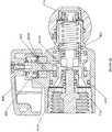
- FIG. 4is a sectional elevation side view of the valve assembly.
- FIG. 5is an exploded view of an alternate preferred embodiment of the valve assembly with some additional and/or different features not illustrated in the previous drawings.
- FIG. 5Ais a perspective view of the cam used with the valve assembly.
- FIG. 5Bis a sectional top elevational view of the valve assembly showing the override assembly in lockout or disengaged position.
- FIG. 5Cis a perspective view of the piston used with the valve assembly.
- FIG. 6is an elevational view of the valve assembly integrated with a showerhead.
- FIG. 7is an illustration of Applicants' valve assembly integrated with a mixing valve or valves.
- FIG. 8is an illustration showing the use of Applicants' valve assembly downstream of mixing valves.
- FIG. 8Ais an illustration of Applicants' valve assembly as part of a larger flow control system, including a wall.
- the valve assembly 18is comprised of the following components: a main body rear 802 , a main body O-ring 804 , a slide spring 806 , a slide 808 , a slide O-ring 810 , a piston spring 812 , a piston 814 , two piston O-rings 816 , a screen 818 , a body front 820 , an actuator 822 , a release pin 830 , a release pin spring 832 , and a pin retention ring 834 .
- the valve assembly housing 12is comprised of the following components: a housing first part 824 , a housing second part 826 , and a handle 828 .
- the main body O-ring 804 , slide spring 806 , and the longer end of the slide 808are operably inserted into the wider, threaded end of the body rear 802 .
- the main bodyis comprised of body rear 802 and body front 820 .
- the piston spring 812 , a first piston O-ring 816 , the piston 814 , and a second piston O-ring 816are operably inserted into the wider, threaded end of the body rear 802 .
- the screen 818 and the slide O-ring 810are operably inserted into the wider end of the body front 820 .
- the wider, threaded end of the body rear 802is operably coupled to the wider end of the body front 820 to enclose the aforementioned components.
- the temperature sensor and actuator 822is operably inserted into the narrower end of the body front 820 .
- the release pin 830is operably inserted into body rear 802 with the release pin spring 832 .
- the housing first part 824 and the housing second part 826are operably coupled to substantially enclose the valve assembly 18 and the handle 828 is operably coupled to the release pin 830 .
- a handle screw 836is used to operably couple the handle 828 with release pin 830 .
- Body rear 802further includes main body outlet port 802 A, release pin housing 802 B, spring retainer 802 D, and stop lip 802 C.
- Slide 808further includes slide nose 808 A, slide head 808 B, slide head lower surface 808 C, hollow slide body 808 D, and slide ports 808 E for controlling the flow of water through the valve assembly.
- Piston spring 812is dimensioned for receipt into hollow slide body 808 D and to abut at a front end piston base 814 B and at a second end spring retainer 802 D.
- Piston 814includes piston head 814 A, piston base 814 B, piston stem 814 C, and piston head cavity 814 D.
- Piston head 814 Aincludes a piston head cavity 814 D for receipt of actuator nose 822 B there into.
- Body front 820includes body end shoulder 820 A capable of receiving and stopping the motion of slide 808 as urged in an upstream direction by slide spring 806 .
- Body front 820also defines, at an upstream end, inlet port 820 B.
- Body front 820is seen to have threaded walls for threaded engagement with body rear 802 .
- Actuator 822is seen to have threaded walls 822 A for threaded engagement with threaded walls 820 C of body front 820 .
- Actuator 822also has actuator nose 822 B shaped to fit snug within piston head cavity 814 D as seen in FIG. 1A , for example.
- FIG. 1Aalso illustrates a channel 814 E (see also FIGS. 5B and 5C ) through piston head 814 A, which will allow a small amount of water to flow through the valve even when in the shutoff position illustrated in FIG. 2A .
- FIGS. 1 , 1 A, and 1 Billustrate valve assembly 18 .
- FIGS. 1A and 1Billustrate Applicant's novel valve assembly 18 in an open condition (cool water flow through slide ports 808 E illustrated by arrows) and with the override locked out or disengaged.
- an increase in water temperature above a predetermined levelwill cause piston 814 to move to the right as indicated in FIG. 2A , the piston moving within slide 808 , so as to shut off fluid flow through slide ports 808 E when piston head 814 A has moved far enough, that is, to the position as illustrated in FIG. 2A .
- FIGS. 3A and 3Billustrate the novel valve assembly 18 after the user has elected to manually rotate handle 828 , so as to withdraw release pin 830 from the rear of slide head 808 B.
- the movement of slide 808 under the impetus of water pressure upstream of slide head 808 Bwill overcome the pressure exerted by slide spring 806 and move the slide downstream and against annular stop lip 802 C in body rear 802 .
- This movementwill uncover slide ports 808 E and allow water (as well as water above the cutoff temperature) to resume flow through hollow sections of piston 814 and slide 808 and out outlet port 802 A.
- the usercan adjust the water mix to the desired temperature above or below the cutoff temperature when in the bypass engaged condition illustrated in FIGS. 3A and 3B .
- the userWhen the user is through with showering, the user will simply shut off the mixing valves which are typically upstream of valve assembly 18 .
- slide spring 806will allow slide 808 to move to the left or “upstream.”
- release pin 830 under the impetus of release pin spring 832will move to the lockout position as illustrated in FIGS. 1A and 1B , thus automatically resetting the override to a pre-override position.
- other mechanical or electrical meansmay be used to achieve this function, including direct mechanical engagement with the mixing valves or position/pressure sensors combined with actuators to move the slide.
- FIGS. 5 and 5Billustrate an additional embodiment of the device as set forth herein which has some additional and/or different features. Further, FIG. 5 , given that it is a cross-sectional perspective view, will help further illustrate the structure of some of the elements of the invention shown in the earlier Figures.
- FIG. 5illustrates the manner in which body front 820 includes threaded walls 820 C, which allow secure engagement with actuator 822 .
- Screen 818may be sandwiched between body 820 and main body rear 802 to provide for filtering of water passing through the valve assembly.
- FIG. 1illustrates a pair of O-rings 816 fitted by compression to grooves in outer walls of piston 814
- a piston gland O-ring 710may be provided fitable to a groove on the inner walls of piston head 814 A. Gland O-ring 710 will make contact with the actuator nose 822 B as seen in FIG. 5B .
- the embodiment illustrated in FIGS. 5 and 5Chas a piston with three O-rings, two on the outside and one gland O-ring on the inside to contact the actuator. The two on the outside will be maintained in their groove under compression and will contact the inner walls of the slide as seen in FIGS. 1 , 1 A, and 5 B, for example.
- gland O-ring 710is to help seal off water
- the use of the three O-rings, including the ones at the ends of the piston,will help provide a “cushion” and a “drag” that will provide dampening and thus help reduce the likelihood from “hammering” that may occur.
- a release assemblywhose function it is to release slide 808 and therefore activate the bypass or override function as seen in FIGS. 3A and 3B are seen to include: handle screw 836 for engaging handle 828 and extending therethrough to engage release pin threaded portion 830 C of release pin 830 .
- Pin cylinder cap 700having cap threaded area 700 A, screws into a threaded area on release pin housing 802 B of body rear 802 . With this, it can be seen that the release pin spring 832 will act on release pin land 830 B.
- a release pin actuated by a handlethe release pin having cam pin 831 , will always urge release pin 830 towards an engaged or interference position as illustrated in FIGS. 5 and 5B .
- release pin 830has a hole 830 D in release pin arm 830 A to receive cam pin 831 (shown in FIG. 5B ) and would be perpendicular to release pin arm 830 A and extend through the hole 830 B.
- cam 706is insertable into release pin housing 802 B and has boss 706 A that will seat into the hole 802 G slots in the base of release pin housing 802 B.
- Central opening 706 C in cam 706is dimensioned to allow arm 830 A to extend through the cam and through opening 802 E in the base of release pin housing 820 B, so as to be capable of reaching the position which locks out the override ( FIGS. 1A , 2 A, and 5 B).
- FIGS. 5 , 5 A, and 5 Balso illustrate curved portion 706 B of cam 706 , which allows cam pin 831 to ride up the curved portion against pressure of release pin spring 832 when the handle is rotated. Riding up from the position seen in FIG. 5B will allow release pin arm 830 A to withdraw from the interference or lockout position, and “release” to allow the override or bypass to engage. Note that even in position with the override engaged ( FIG. 3A ), release spring 832 is urging release pin arm against the outside walls of slide head 808 B, so as soon as the slide moves forward (responsive to the mixing valves being shut off, for example), the release pin arm 830 A will automatically engage the rear of the slide head 808 B( FIGS. 1A , 2 A, and 5 B) to lock out the override.
- FIG. 5Billustrates an embodiment of piston 814 with two small channels 814 E and 814 F in piston head 814 A that will allow water to trickle through the valve even when it is in an off position. This will help prevent cross-flow on worn mixing valves and acts as a hydraulic dampener to prevent “hammering.” It is seen from FIG. 5B that, if the piston moved to a port flow blocking position, channels 814 E and 814 F would provide for the trickle flow of water through the valves. Further, the effect of gland O-ring 710 against the actuator nose combined with the two small channels 814 E and 814 F provides a “piston pump” hydraulic action to help prevent by dampening to potential hammering. The piston base 814 B helps stabilize the piston in the slide and also helps prevent hammering.
- FIG. 5also illustrates the use of a flow restrictor 714 here designed to limit the flow to about 2.5 gallons per minute under typical pressures, as may be found in valves when the mixing valves are open and the valve is allowing water to flow therethrough.
- the position of the flow restrictoris typically downstream of the main body and the control elements of the valve.
- FIG. 5is also seen to include a ball 716 for engagement with main body rear 802 with, for example, the use of threads. Ball 716 will allow rotation with elements downstream thereof, for example, as set forth in FIG. 5B .
- FIG. 6shows valve assembly 18 with ball 716 on the upstream end and attached to body front 820 by threadable means.
- ball 716may be utilized on either the upstream or downstream end of the body.
- FIG. 6also illustrates the use of the valve inside a custom showerhead 42 .
- housing parts 824 / 826may be omitted.
- the valve, except the handle,may be enclosed within the body of the showerhead, forming an integrated showerhead/valve unit.
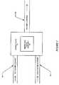
- FIGS. 7 and 8illustrate the use of Applicants' novel valve assembly 18 in a larger environment as part of a water flow control system.
- FIG. 7illustrates that the novel valve assembly 18 may be physically incorporated into the same housing as the mixing valves or valves 72 .
- Mixing valve 72would typically receive water from a hot water conduit 74 and a cold water conduit 76 .
- Integrated within the same assembly housing as mixing valves which control the amount of hot and cold water coming into a single delivery conduit 78may be the restrictive valve assembly 18 .
- valve assembly 18may be downstream from mixing valve 72 and in line with a delivery conduit 78 .
- valve assembly 18is downstream of a mixing valve and upstream of a showerhead (not shown).
- FIG. 8Aillustrates Applicants' novel valve assembly 18 in a larger environment as part of a water flow control system.
- FIG. 8Aillustrates hat Applicants may provide a wall 882 to substantially isolate, from the user and the environment in which the user will bathe, elements including mixing valve 72 excepting handle, which would be exposed through wall 882 for manual manipulation by the user.
- Mixing valve or valves 72are known in the art for receiving water from cold water conduit 76 and hot water conduit 74 .
- Applicants' water flow control systemmay include a diverter valve 884 downstream, typically, of valve assembly 18 to, for example, divert water from a showerhead flow or a tub faucet flow.
- Applicants' temperature sensing mechanismfor example, actuator 822
- actuator 822is advantageously, but not necessarily, placed in the most upstream position so a to better respond to temperature changes and avoid the heat sink effect of elements downstream of the actuator.
- Applicants' sensoris pushing the piston in a downstream direction as it expands, that is, pushing in a direction that is assisted by the water pressure, moving the piston, as illustrated in the drawings from left to right.
- Actuator 822is, in one embodiment, a wax actuator adapted to respond by expanding in a range of approximately 90° F. to 110° F., such as an actuator manufactured by Vernet as Model Nos. A034 and A092/P.
- Element 822both senses temperature changes and responds, as by expanding or contracting to such change.
- the sensing and actuating functionsmay be achieved through separate elements however.
- Other temperature actuators/sensorssuch as a temperature responsive memory wire, a bimetallic element, or other known and appropriate temperature responsive phase change materials, or electromechanically operated temperature sensors may be used in conjunction with Applicants' novel valve assembly, such as those known in the art.
- the slidewill typically have an upstream slide head area that is responsive to water pressure in urging the slide to a downstream direction.
- the pistontypically would have an area exposed to water pressure upstream that would tend to move it to a downstream position.
- area on the slidehere seen to be an annular ring, is significantly larger than the piston head area.
- the override featuremay be actuated with a lanyard, chain, electronic button, switch and optical or other sensor.
- a visual/audible indicator 829may be used to indicate that the shower is ready (that is, when the temperature actuator has restricted the flow of water).
- a visual or audible “reminder”may be used, including a popout indicator or a constant or blinking light. Temperature or pressure actuated visible or audio indicators may also be used.
- FIGS. 1 and 5Billustrate the use of a gland O-ring 804 situated and engaged with the body walls near the downstream end of slide 808 when the slide is in its upstream most position.
- O-ring 810is seen to engage the slide head.
- the use of a gland O-ringwill “swipe” the slide along with its position at the downstream end of the slide helps, among other things, decrease mineral deposits buildup on the slide.
- O-ring 810will swipe the channel walls of the body when the slide moves.
- the use of the O-rings in these positionshelps prevent drying out which tends to create scale and scale tends to impede the proper effective operation of the elements.
- a lubricantsuch as a silicon based lubricant, is provided to keep the channel and slide walls lubricated.
- Applicants' novel valvemay be located in between the shower arm and the showerhead using matching threads. It may also be incorporated into the showerhead.
- Applicants' novel valve assemblymay be retrofitable to many shower arms by removing existing threaded showerheads and inserting in the space between the showerhead and the end of the shower arm, Applicants' novel valve and threading the showerhead to the downstream end after threading the valve into the end of the threaded end of the shower arm.
- the valvemay also be built into the shower arm or shower stall/tub walls (see FIG. 8A ).
Landscapes
- Engineering & Computer Science (AREA)
- General Engineering & Computer Science (AREA)
- Physics & Mathematics (AREA)
- Hydrology & Water Resources (AREA)
- Health & Medical Sciences (AREA)
- Life Sciences & Earth Sciences (AREA)
- Public Health (AREA)
- Water Supply & Treatment (AREA)
- Mechanical Engineering (AREA)
- Fluid Mechanics (AREA)
- General Physics & Mathematics (AREA)
- Automation & Control Theory (AREA)
- Temperature-Responsive Valves (AREA)
- Domestic Plumbing Installations (AREA)
Abstract
Description
Claims (29)
Priority Applications (7)
| Application Number | Priority Date | Filing Date | Title |
|---|---|---|---|
| US11/788,884US7878417B2 (en) | 2005-06-15 | 2007-04-23 | Multifunctional restrictive valve |
| US12/807,719US8464962B2 (en) | 2005-02-22 | 2010-09-13 | 3-stage temperature control valve |
| US12/966,471US8434693B2 (en) | 2006-04-25 | 2010-12-13 | Multifunctional restrictive valve |
| US13/857,705US9309655B2 (en) | 2005-06-15 | 2013-04-05 | Multifunctional restrictive valve |
| US15/082,950US9611629B2 (en) | 2005-06-15 | 2016-03-28 | Multifunctional restrictive valve |
| US15/478,065US9927042B2 (en) | 2005-06-15 | 2017-04-03 | Multifunctional restrictive valve |
| US15/936,295US10808857B2 (en) | 2005-06-15 | 2018-03-26 | Multifunctional restrictive valve |
Applications Claiming Priority (3)
| Application Number | Priority Date | Filing Date | Title |
|---|---|---|---|
| US11/154,404US7681804B2 (en) | 2005-01-14 | 2005-06-15 | Methods and apparatus for an automatic temperature-controlled valve |
| US79473506P | 2006-04-25 | 2006-04-25 | |
| US11/788,884US7878417B2 (en) | 2005-06-15 | 2007-04-23 | Multifunctional restrictive valve |
Related Parent Applications (2)
| Application Number | Title | Priority Date | Filing Date |
|---|---|---|---|
| US11/154,404Continuation-In-PartUS7681804B2 (en) | 2005-01-14 | 2005-06-15 | Methods and apparatus for an automatic temperature-controlled valve |
| US11/154,404ContinuationUS7681804B2 (en) | 2005-01-14 | 2005-06-15 | Methods and apparatus for an automatic temperature-controlled valve |
Related Child Applications (2)
| Application Number | Title | Priority Date | Filing Date |
|---|---|---|---|
| US12/807,719Continuation-In-PartUS8464962B2 (en) | 2005-02-22 | 2010-09-13 | 3-stage temperature control valve |
| US12/966,471ContinuationUS8434693B2 (en) | 2005-06-15 | 2010-12-13 | Multifunctional restrictive valve |
Publications (2)
| Publication Number | Publication Date |
|---|---|
| US20070194141A1 US20070194141A1 (en) | 2007-08-23 |
| US7878417B2true US7878417B2 (en) | 2011-02-01 |
Family
ID=38656132
Family Applications (6)
| Application Number | Title | Priority Date | Filing Date |
|---|---|---|---|
| US11/788,884Active2027-08-26US7878417B2 (en) | 2005-02-22 | 2007-04-23 | Multifunctional restrictive valve |
| US12/966,471Active2025-11-02US8434693B2 (en) | 2005-06-15 | 2010-12-13 | Multifunctional restrictive valve |
| US13/857,705Expired - LifetimeUS9309655B2 (en) | 2005-06-15 | 2013-04-05 | Multifunctional restrictive valve |
| US15/082,950Expired - LifetimeUS9611629B2 (en) | 2005-06-15 | 2016-03-28 | Multifunctional restrictive valve |
| US15/478,065Expired - LifetimeUS9927042B2 (en) | 2005-06-15 | 2017-04-03 | Multifunctional restrictive valve |
| US15/936,295Expired - LifetimeUS10808857B2 (en) | 2005-06-15 | 2018-03-26 | Multifunctional restrictive valve |
Family Applications After (5)
| Application Number | Title | Priority Date | Filing Date |
|---|---|---|---|
| US12/966,471Active2025-11-02US8434693B2 (en) | 2005-06-15 | 2010-12-13 | Multifunctional restrictive valve |
| US13/857,705Expired - LifetimeUS9309655B2 (en) | 2005-06-15 | 2013-04-05 | Multifunctional restrictive valve |
| US15/082,950Expired - LifetimeUS9611629B2 (en) | 2005-06-15 | 2016-03-28 | Multifunctional restrictive valve |
| US15/478,065Expired - LifetimeUS9927042B2 (en) | 2005-06-15 | 2017-04-03 | Multifunctional restrictive valve |
| US15/936,295Expired - LifetimeUS10808857B2 (en) | 2005-06-15 | 2018-03-26 | Multifunctional restrictive valve |
Country Status (6)
| Country | Link |
|---|---|
| US (6) | US7878417B2 (en) |
| EP (1) | EP2013424B1 (en) |
| AU (1) | AU2007243474B2 (en) |
| CA (1) | CA2650304C (en) |
| NZ (1) | NZ572339A (en) |
| WO (1) | WO2007127189A2 (en) |
Cited By (11)
| Publication number | Priority date | Publication date | Assignee | Title |
|---|---|---|---|---|
| US20120261496A1 (en)* | 2008-04-15 | 2012-10-18 | Mordechai Lev | Showerhead with touch based multimodal operation |
| WO2014056227A1 (en)* | 2012-10-14 | 2014-04-17 | Yuan Dejun | Remote control electrovalve |
| WO2015021131A1 (en)* | 2013-08-06 | 2015-02-12 | Fluid Handling Llc | Low water cutoff switch |
| US20160010759A1 (en)* | 2013-03-11 | 2016-01-14 | Neoperl Gmbh | Sanitary installations and shower assembly |
| US9387493B2 (en) | 2008-04-15 | 2016-07-12 | Sidus Technologies, Inc. | Showerhead with touch based multimodal rechargeable battery operation |
| US9581255B2 (en) | 2012-07-23 | 2017-02-28 | Henning, Inc. | Multiple proportion delivery systems and methods |
| US10648586B1 (en) | 2018-11-20 | 2020-05-12 | Therm-Omega-Tech, Inc. | Automated drain valve with internal reset |
| US10753071B2 (en) | 2013-10-09 | 2020-08-25 | Evolve Technologies, Llc | Tub faucet having a control valve with reduced backpressure |
| US10967390B2 (en) | 2017-12-01 | 2021-04-06 | Evolve Technologies, Llc | Efficient showerhead with purge outlet |
| US11697929B2 (en) | 2019-01-18 | 2023-07-11 | Geberit International Ag | Anti-scald device for fluid supply system having hot water disinfection |
| US12215487B1 (en) | 2013-10-09 | 2025-02-04 | Am Conservation Group | Tub faucet having a control valve with reduced backpressure |
Families Citing this family (25)
| Publication number | Priority date | Publication date | Assignee | Title |
|---|---|---|---|---|
| WO2010022566A1 (en)* | 2008-08-29 | 2010-03-04 | Lin Wenjuan | A temperature-controlled water-saving device |
| US8807521B2 (en) | 2010-05-25 | 2014-08-19 | Kerry Dunki-Jacobs | Flow control system |
| US9657464B2 (en) | 2010-05-25 | 2017-05-23 | Kerry Dunki-Jacobs | Flow control system |
| EP2418408B1 (en)* | 2010-08-12 | 2013-09-18 | Honeywell Technologies Sarl | Regulation valve |
| CN102777674B (en)* | 2011-05-10 | 2014-09-17 | 厦门松霖科技有限公司 | High-temperature protection valve and sprinkler with high-temperature protection valve |
| EP2523065B1 (en)* | 2011-05-10 | 2015-09-09 | Honeywell Technologies Sarl | Regulation valve and method for calibrating such a regulation valve |
| WO2013091108A1 (en) | 2011-12-22 | 2013-06-27 | Dana Canada Corporation | Heat exchanger with integrated thermal bypass valve |
| USD772898S1 (en) | 2013-03-15 | 2016-11-29 | H2 & Wf3 Research, Llc | Display screen with graphical user interface for a document management system |
| USD788115S1 (en) | 2013-03-15 | 2017-05-30 | H2 & Wf3 Research, Llc. | Display screen with graphical user interface for a document management system |
| CN103234064B (en)* | 2013-04-22 | 2016-04-06 | 恺霖卫浴科技(厦门)有限公司 | A kind of temperature-sensitive water outlet device |
| DE102013111618A1 (en)* | 2013-10-22 | 2015-04-23 | Dr. Ing. H.C. F. Porsche Aktiengesellschaft | thermostatic valve |
| CN104914894A (en)* | 2015-04-20 | 2015-09-16 | 河南科技大学 | Shower water temperature adjustment and control device |
| US9757741B2 (en) | 2015-09-14 | 2017-09-12 | Fan Fi International, Inc. | Thermal and audio controlled valve and showerhead assembly |
| WO2017160322A1 (en) | 2016-03-18 | 2017-09-21 | Evolve Technologies, Llc | Tub faucet having a control valve without hammering |
| US9803345B1 (en)* | 2016-06-15 | 2017-10-31 | Xiamen Lota International Co., Ltd. | Single waterway shaft structure |
| US10913084B2 (en) | 2016-08-09 | 2021-02-09 | Oasense | Electronic showerhead device |
| CN108654861B (en)* | 2017-04-01 | 2019-07-09 | 厦门松霖科技股份有限公司 | With the combination shower for arranging cold function |
| CN109404565B (en)* | 2017-08-15 | 2024-10-15 | 厦门松霖科技股份有限公司 | Cold discharge switching valve and switching method thereof |
| US10006552B1 (en)* | 2017-08-16 | 2018-06-26 | Edward Herbert | Water and energy saving thermostatic valve |
| GB2568271B (en)* | 2017-11-09 | 2020-04-22 | Kohler Mira Ltd | A plumbing component for controlling the mixture of two supplies of water |
| CN111219869B (en)* | 2018-11-23 | 2021-07-16 | 宁波方太厨具有限公司 | Gas water heater and method for preventing turbine flow sensor from being stuck |
| DE202019103892U1 (en)* | 2019-07-15 | 2020-10-16 | Neoperl Gmbh | Volume control unit and corresponding use |
| DE102020119064A1 (en) | 2020-07-20 | 2022-01-20 | Neoperl Gmbh | water pipe connector |
| CN112555464B (en)* | 2020-11-16 | 2025-04-29 | 厦门市得尔美卫浴有限公司 | Anti-scalding component |
| US12352022B2 (en) | 2022-12-29 | 2025-07-08 | Paul Sapsara | Point-of-use instant hot water shower head dispenser |
Citations (16)
| Publication number | Priority date | Publication date | Assignee | Title |
|---|---|---|---|---|
| US2556777A (en) | 1949-02-11 | 1951-06-12 | Christian J Reimuller | Thermostatically controlled valve for shower heads |
| US3263926A (en) | 1963-11-06 | 1966-08-02 | Dole Valve Co | Anti-scald shower control |
| US3742521A (en)* | 1971-04-09 | 1973-07-03 | Kohler Co | Whirlpool attachment for tubs |
| US3935998A (en)* | 1972-09-20 | 1976-02-03 | Robertshaw Controls Company | Valve construction and system utilizing the same |
| US4281790A (en) | 1980-05-02 | 1981-08-04 | Mcginnis Merrill F | Safety shower head |
| US4523604A (en)* | 1983-03-14 | 1985-06-18 | Masco Corporation Of Indiana | Diverter valve |
| US4834873A (en)* | 1988-08-17 | 1989-05-30 | Burrows Bruce D | Combined reverse osmosis unit and water inflow control valve for a water purification system |
| WO1991011643A1 (en) | 1990-01-23 | 1991-08-08 | Rundle Gregory E | Manual override heat sensitive valve |
| US5271559A (en)* | 1992-09-03 | 1993-12-21 | Chrysler Corporation | Thermal isolation device for heater core to prevent over-heat damage |
| US5368227A (en) | 1993-11-16 | 1994-11-29 | Mcginnis; Merrill F. | Temperature limiting control valve for a shower head |
| US5408709A (en)* | 1990-05-03 | 1995-04-25 | Lockwood; George H. | Shower control assembly |
| US5560541A (en) | 1995-04-28 | 1996-10-01 | I.W. Industries, Inc. | Anti-scald valve for bathroom showers |
| GB2303685A (en) | 1995-07-21 | 1997-02-26 | Reliance Water Controls Limite | Hot and cold water mixer control |
| US5826790A (en) | 1997-07-17 | 1998-10-27 | Sentry Equipment Corp. | Temperature-sensitive shutoff valve |
| US20020069655A1 (en) | 2000-12-07 | 2002-06-13 | Jae-Heung Lee | Automatic temperature control valve |
| US6899132B2 (en)* | 2002-12-27 | 2005-05-31 | Nitto Kohki Co., Ltd. | Fluid coupler |
Family Cites Families (28)
| Publication number | Priority date | Publication date | Assignee | Title |
|---|---|---|---|---|
| US3118648A (en)* | 1963-02-20 | 1964-01-21 | American Radiator & Standard | Thermostatic flow control valve |
| US3420293A (en)* | 1967-05-04 | 1969-01-07 | United Aircraft Prod | Tubular heat exchanger with thermostatic valve |
| US3768731A (en)* | 1971-08-25 | 1973-10-30 | Altair Inc | Fail safe thermostatic switch |
| US4431020A (en)* | 1981-10-08 | 1984-02-14 | Marotta Scientific Controls, Inc. | Flow-control system having a wide range of flow-rate control |
| US4878512A (en)* | 1983-01-25 | 1989-11-07 | Ogontz Controls Company | Valve mechanism |
| US4460007A (en)* | 1983-01-25 | 1984-07-17 | Pirkle Fred L | Valve mechanism |
| KR890001016B1 (en)* | 1984-12-11 | 1989-04-18 | 마쯔시다덴기산교 가부시기가이샤 | Hotwater mixing valve apparatus |
| US4678002A (en)* | 1985-05-10 | 1987-07-07 | Valley Harold J | Faucet valve with adjustable stem tightener |
| DE3519034A1 (en)* | 1985-05-25 | 1986-11-27 | Alfred Dipl.-Ing. 4330 Mülheim Epe | PRE-CONTROLLED VALVE IN PIPE FLANGE DESIGN |
| US4638828A (en)* | 1985-10-22 | 1987-01-27 | Barrineau Sr Wyman L | Water temperature actuated drip valve |
| US4854499A (en)* | 1985-12-11 | 1989-08-08 | Eli Neuman | Temperature sensitive shower diverter valve and method for diverting shower water |
| US4762273A (en)* | 1986-03-07 | 1988-08-09 | Stephen O. Gregory | Electronic faucet with spout position sensing means |
| US4848388A (en)* | 1987-10-19 | 1989-07-18 | Memory Metals, Inc. | Emergency valve with test capability |
| US5062164A (en)* | 1989-06-01 | 1991-11-05 | Lee Chang H | Automatic mixing faucet |
| US5462224A (en)* | 1990-10-05 | 1995-10-31 | Toto Ltd. | Hot and cold water mixing discharge device |
| US5141153A (en)* | 1990-02-20 | 1992-08-25 | Moen Incorporated | Energy conservation and anti-scald/burn single handle valve construction |
| US5390899A (en)* | 1992-10-26 | 1995-02-21 | Perez C.; Sergio | Flow valve operated by the angular or cross displacement of an axial stem |
| US5397099A (en)* | 1993-03-31 | 1995-03-14 | Pilolla; Joseph J. | Sink arrangement with faucet having dual operational mode |
| US5826613A (en)* | 1993-05-19 | 1998-10-27 | Georg Fischer Rohrleitungssysteme Ag | Flow control valve |
| US5931375A (en)* | 1994-09-23 | 1999-08-03 | Frese Armatur A/S | Valve for a system having an energy-carrying medium |
| DE19710782C2 (en)* | 1997-03-17 | 2002-08-01 | Ideal Standard | plumbing fixture |
| US6029686A (en)* | 1997-05-07 | 2000-02-29 | Pirkle; Fred L. | Thermally responsive valve |
| US5915665A (en)* | 1997-10-27 | 1999-06-29 | Kohler Co. | Latching solenoid valve |
| RU2159377C1 (en)* | 1999-02-23 | 2000-11-20 | Открытое акционерное общество НПО Энергомаш им. акад. В.П. Глушко | Flowmeter |
| US6286764B1 (en)* | 1999-07-14 | 2001-09-11 | Edward C. Garvey | Fluid and gas supply system |
| US6929187B2 (en)* | 2000-10-25 | 2005-08-16 | Grundfos Pumps Manufacturing Corporation | Water control fixture having thermostatically controlled bypass valve |
| US6616058B1 (en)* | 2002-06-14 | 2003-09-09 | Therm-Omega-Tech, Inc. | Valve |
| US7971601B2 (en)* | 2007-07-02 | 2011-07-05 | Grundfos Pumps Corporation | Water circulation system valve assemblies having water temperature control |
- 2007
- 2007-04-23USUS11/788,884patent/US7878417B2/enactiveActive
- 2007-04-23NZNZ572339Apatent/NZ572339A/ennot_activeIP Right Cessation
- 2007-04-23EPEP07755947.4Apatent/EP2013424B1/ennot_activeNot-in-force
- 2007-04-23CACA2650304Apatent/CA2650304C/ennot_activeExpired - Fee Related
- 2007-04-23WOPCT/US2007/009902patent/WO2007127189A2/enactiveApplication Filing
- 2007-04-23AUAU2007243474Apatent/AU2007243474B2/ennot_activeCeased
- 2010
- 2010-12-13USUS12/966,471patent/US8434693B2/enactiveActive
- 2013
- 2013-04-05USUS13/857,705patent/US9309655B2/ennot_activeExpired - Lifetime
- 2016
- 2016-03-28USUS15/082,950patent/US9611629B2/ennot_activeExpired - Lifetime
- 2017
- 2017-04-03USUS15/478,065patent/US9927042B2/ennot_activeExpired - Lifetime
- 2018
- 2018-03-26USUS15/936,295patent/US10808857B2/ennot_activeExpired - Lifetime
Patent Citations (17)
| Publication number | Priority date | Publication date | Assignee | Title |
|---|---|---|---|---|
| US2556777A (en) | 1949-02-11 | 1951-06-12 | Christian J Reimuller | Thermostatically controlled valve for shower heads |
| US3263926A (en) | 1963-11-06 | 1966-08-02 | Dole Valve Co | Anti-scald shower control |
| US3742521A (en)* | 1971-04-09 | 1973-07-03 | Kohler Co | Whirlpool attachment for tubs |
| US3935998A (en)* | 1972-09-20 | 1976-02-03 | Robertshaw Controls Company | Valve construction and system utilizing the same |
| US4281790A (en) | 1980-05-02 | 1981-08-04 | Mcginnis Merrill F | Safety shower head |
| US4523604A (en)* | 1983-03-14 | 1985-06-18 | Masco Corporation Of Indiana | Diverter valve |
| US4834873A (en)* | 1988-08-17 | 1989-05-30 | Burrows Bruce D | Combined reverse osmosis unit and water inflow control valve for a water purification system |
| US5123593A (en) | 1990-01-23 | 1992-06-23 | Rundle Gregory E | Manual override heat sensitive valve |
| WO1991011643A1 (en) | 1990-01-23 | 1991-08-08 | Rundle Gregory E | Manual override heat sensitive valve |
| US5408709A (en)* | 1990-05-03 | 1995-04-25 | Lockwood; George H. | Shower control assembly |
| US5271559A (en)* | 1992-09-03 | 1993-12-21 | Chrysler Corporation | Thermal isolation device for heater core to prevent over-heat damage |
| US5368227A (en) | 1993-11-16 | 1994-11-29 | Mcginnis; Merrill F. | Temperature limiting control valve for a shower head |
| US5560541A (en) | 1995-04-28 | 1996-10-01 | I.W. Industries, Inc. | Anti-scald valve for bathroom showers |
| GB2303685A (en) | 1995-07-21 | 1997-02-26 | Reliance Water Controls Limite | Hot and cold water mixer control |
| US5826790A (en) | 1997-07-17 | 1998-10-27 | Sentry Equipment Corp. | Temperature-sensitive shutoff valve |
| US20020069655A1 (en) | 2000-12-07 | 2002-06-13 | Jae-Heung Lee | Automatic temperature control valve |
| US6899132B2 (en)* | 2002-12-27 | 2005-05-31 | Nitto Kohki Co., Ltd. | Fluid coupler |
Non-Patent Citations (1)
| Title |
|---|
| PCT Notification of Transmittal of the International Search Report and the Written Opinion of the International Searching Authority, or Declaration, dated Oct. 27, 2008. |
Cited By (16)
| Publication number | Priority date | Publication date | Assignee | Title |
|---|---|---|---|---|
| US9387493B2 (en) | 2008-04-15 | 2016-07-12 | Sidus Technologies, Inc. | Showerhead with touch based multimodal rechargeable battery operation |
| US20120261496A1 (en)* | 2008-04-15 | 2012-10-18 | Mordechai Lev | Showerhead with touch based multimodal operation |
| US9581255B2 (en) | 2012-07-23 | 2017-02-28 | Henning, Inc. | Multiple proportion delivery systems and methods |
| WO2014056227A1 (en)* | 2012-10-14 | 2014-04-17 | Yuan Dejun | Remote control electrovalve |
| US9677680B2 (en)* | 2013-03-11 | 2017-06-13 | Neoperl Gmbh | Sanitary installations and shower assembly |
| US20160010759A1 (en)* | 2013-03-11 | 2016-01-14 | Neoperl Gmbh | Sanitary installations and shower assembly |
| US9714717B2 (en) | 2013-08-06 | 2017-07-25 | Fluid Handling Llc | Flow switch assembly featuring two-part base assembly with non-metallic upper part and metallic lower part |
| WO2015021131A1 (en)* | 2013-08-06 | 2015-02-12 | Fluid Handling Llc | Low water cutoff switch |
| US12215487B1 (en) | 2013-10-09 | 2025-02-04 | Am Conservation Group | Tub faucet having a control valve with reduced backpressure |
| US10753071B2 (en) | 2013-10-09 | 2020-08-25 | Evolve Technologies, Llc | Tub faucet having a control valve with reduced backpressure |
| US11492787B2 (en) | 2013-10-09 | 2022-11-08 | Evolve Technologies, Llc | Tub faucet having a control valve with reduced backpressure |
| US10967390B2 (en) | 2017-12-01 | 2021-04-06 | Evolve Technologies, Llc | Efficient showerhead with purge outlet |
| US12275023B2 (en) | 2017-12-01 | 2025-04-15 | Am Conservation Group | Efficient showerhead with purge outlet |
| US11833529B2 (en) | 2017-12-01 | 2023-12-05 | Am Conservation Group | Efficient showerhead with purge outlet |
| US10648586B1 (en) | 2018-11-20 | 2020-05-12 | Therm-Omega-Tech, Inc. | Automated drain valve with internal reset |
| US11697929B2 (en) | 2019-01-18 | 2023-07-11 | Geberit International Ag | Anti-scald device for fluid supply system having hot water disinfection |
Also Published As
| Publication number | Publication date |
|---|---|
| AU2007243474B2 (en) | 2011-07-28 |
| CA2650304C (en) | 2011-09-13 |
| EP2013424B1 (en) | 2017-06-07 |
| US9927042B2 (en) | 2018-03-27 |
| NZ572339A (en) | 2011-12-22 |
| US20140196801A1 (en) | 2014-07-17 |
| WO2007127189A9 (en) | 2008-01-03 |
| US9611629B2 (en) | 2017-04-04 |
| AU2007243474A1 (en) | 2007-11-08 |
| WO2007127189A2 (en) | 2007-11-08 |
| US20170219113A1 (en) | 2017-08-03 |
| WO2007127189A3 (en) | 2008-12-18 |
| US20070194141A1 (en) | 2007-08-23 |
| US10808857B2 (en) | 2020-10-20 |
| US20180216747A1 (en) | 2018-08-02 |
| CA2650304A1 (en) | 2007-11-08 |
| US20110079296A1 (en) | 2011-04-07 |
| US8434693B2 (en) | 2013-05-07 |
| US20160251837A1 (en) | 2016-09-01 |
| EP2013424A2 (en) | 2009-01-14 |
| US9309655B2 (en) | 2016-04-12 |
Similar Documents
| Publication | Publication Date | Title |
|---|---|---|
| US10808857B2 (en) | Multifunctional restrictive valve | |
| US8464962B2 (en) | 3-stage temperature control valve | |
| US9737899B2 (en) | Water control system having a temperature controlled tub faucet valve | |
| US4398668A (en) | Showerhead control | |
| US4210284A (en) | Temperature limiting device | |
| US12275023B2 (en) | Efficient showerhead with purge outlet | |
| US8312897B2 (en) | Diverter valve | |
| US11492787B2 (en) | Tub faucet having a control valve with reduced backpressure | |
| AU2005297588B2 (en) | Sanitary thermostatic mixing valve | |
| US10301800B2 (en) | Tub faucet having a control valve with reduced backpressure | |
| JP2006283274A (en) | Water spouting device | |
| US12215487B1 (en) | Tub faucet having a control valve with reduced backpressure | |
| JP2981813B2 (en) | Hot water mixing faucet | |
| CN115727156A (en) | Thermostatic valve core and shower |
Legal Events
| Date | Code | Title | Description |
|---|---|---|---|
| AS | Assignment | Owner name:SHOWERSTART, LLC, ARIZONA Free format text:ASSIGNMENT OF ASSIGNORS INTEREST;ASSIGNORS:BROWN, MICHAEL;LOCKHART, JOHN;DOSS, JEFFREY S.;REEL/FRAME:019274/0166 Effective date:20070420 | |
| STCF | Information on status: patent grant | Free format text:PATENTED CASE | |
| FPAY | Fee payment | Year of fee payment:4 | |
| AS | Assignment | Owner name:EVOLVE TECHNOLOGIES, LLC, ARIZONA Free format text:CHANGE OF NAME;ASSIGNOR:SHOWERSTART, LLC;REEL/FRAME:037405/0538 Effective date:20140903 | |
| MAFP | Maintenance fee payment | Free format text:PAYMENT OF MAINTENANCE FEE, 8TH YR, SMALL ENTITY (ORIGINAL EVENT CODE: M2552) Year of fee payment:8 | |
| MAFP | Maintenance fee payment | Free format text:PAYMENT OF MAINTENANCE FEE, 12TH YR, SMALL ENTITY (ORIGINAL EVENT CODE: M2553); ENTITY STATUS OF PATENT OWNER: SMALL ENTITY Year of fee payment:12 | |
| AS | Assignment | Owner name:AM CONSERVATION GROUP, SOUTH CAROLINA Free format text:ASSIGNMENT OF ASSIGNORS INTEREST;ASSIGNOR:EVOLVE TECHNOLOGIES, LLC;REEL/FRAME:064995/0919 Effective date:20230717 | |
| AS | Assignment | Owner name:BAIN CAPITAL CREDIT, LP, MASSACHUSETTS Free format text:SECURITY INTEREST;ASSIGNORS:AM CONSERVATION GROUP, INC.;PLANETECOSYSTEMS, LLC;REEL/FRAME:071905/0305 Effective date:20250801 |