US7877139B2 - Method and device for implantable cardiac stimulus device lead impedance measurement - Google Patents
Method and device for implantable cardiac stimulus device lead impedance measurementDownload PDFInfo
- Publication number
- US7877139B2 US7877139B2US11/525,497US52549706AUS7877139B2US 7877139 B2US7877139 B2US 7877139B2US 52549706 AUS52549706 AUS 52549706AUS 7877139 B2US7877139 B2US 7877139B2
- Authority
- US
- United States
- Prior art keywords
- testing
- voltage
- electrodes
- resistor
- stimulus
- Prior art date
- Legal status (The legal status is an assumption and is not a legal conclusion. Google has not performed a legal analysis and makes no representation as to the accuracy of the status listed.)
- Active, expires
Links
- 230000000747cardiac effectEffects0.000titleclaimsabstractdescription18
- 238000000034methodMethods0.000titleabstractdescription28
- 238000002847impedance measurementMethods0.000titledescription5
- 238000012360testing methodMethods0.000claimsabstractdescription62
- 239000003990capacitorSubstances0.000claimsdescription28
- 230000000638stimulationEffects0.000claimsdescription8
- 238000005070samplingMethods0.000claimsdescription7
- 230000008878couplingEffects0.000claimsdescription5
- 238000010168coupling processMethods0.000claimsdescription5
- 238000005859coupling reactionMethods0.000claimsdescription5
- 238000007599dischargingMethods0.000claims1
- 238000002560therapeutic procedureMethods0.000claims1
- 238000004146energy storageMethods0.000description10
- 238000010586diagramMethods0.000description4
- 238000002513implantationMethods0.000description4
- 210000001519tissueAnatomy0.000description4
- 230000006870functionEffects0.000description3
- 230000004217heart functionEffects0.000description3
- 238000003780insertionMethods0.000description3
- 230000037431insertionEffects0.000description3
- 238000007920subcutaneous administrationMethods0.000description3
- 206010061592cardiac fibrillationDiseases0.000description2
- 230000015556catabolic processEffects0.000description2
- 238000006731degradation reactionMethods0.000description2
- 230000002600fibrillogenic effectEffects0.000description2
- 230000001939inductive effectEffects0.000description2
- 230000003211malignant effectEffects0.000description2
- 238000005259measurementMethods0.000description2
- XUIMIQQOPSSXEZ-UHFFFAOYSA-NSiliconChemical compound[Si]XUIMIQQOPSSXEZ-UHFFFAOYSA-N0.000description1
- 230000005856abnormalityEffects0.000description1
- 238000004891communicationMethods0.000description1
- 230000000694effectsEffects0.000description1
- 238000001914filtrationMethods0.000description1
- 210000003205muscleAnatomy0.000description1
- 230000010287polarizationEffects0.000description1
- 230000033764rhythmic processEffects0.000description1
- 229910052710siliconInorganic materials0.000description1
- 239000010703siliconSubstances0.000description1
Images


Classifications
- A—HUMAN NECESSITIES
- A61—MEDICAL OR VETERINARY SCIENCE; HYGIENE
- A61N—ELECTROTHERAPY; MAGNETOTHERAPY; RADIATION THERAPY; ULTRASOUND THERAPY
- A61N1/00—Electrotherapy; Circuits therefor
- A61N1/18—Applying electric currents by contact electrodes
- A61N1/32—Applying electric currents by contact electrodes alternating or intermittent currents
- A61N1/36—Applying electric currents by contact electrodes alternating or intermittent currents for stimulation
- A61N1/362—Heart stimulators
- A61N1/37—Monitoring; Protecting
- A61N1/3706—Pacemaker parameters
- A—HUMAN NECESSITIES
- A61—MEDICAL OR VETERINARY SCIENCE; HYGIENE
- A61N—ELECTROTHERAPY; MAGNETOTHERAPY; RADIATION THERAPY; ULTRASOUND THERAPY
- A61N1/00—Electrotherapy; Circuits therefor
- A61N1/18—Applying electric currents by contact electrodes
- A61N1/32—Applying electric currents by contact electrodes alternating or intermittent currents
- A61N1/38—Applying electric currents by contact electrodes alternating or intermittent currents for producing shock effects
- A61N1/39—Heart defibrillators
- A61N1/3956—Implantable devices for applying electric shocks to the heart, e.g. for cardioversion
Definitions
- the present inventionis related to the field of implantable medical devices. More specifically, the present invention relates to lead impedance measurement for implantable cardiac stimulation devices.
- FIG. 1An implantable cardiac stimulus device is shown in FIG. 1 .
- the device 10includes a canister 12 that houses electronics for controlling electrical cardiac stimulation.
- An electrode 14may optionally be placed on the canister 12 , and a lead 16 extends from the canister 12 and carries one or more lead electrodes 18 , 20 .
- the devicemay be suited for delivery of cardiac stimulus as a pacing device providing low energy pulses timed to help regularize cardiac function, or may be suited instead for delivery of higher energy pulses to convert a malignant cardiac event to normal sinus rhythm.
- impedances between pairs of electrodes 14 , 18 , 20will generally fall within a known range.
- the device 10may include telemetry circuitry/devices allowing it to communicate from an implanted position with an associated programmer. Such communication may include annunciation of a lead impedance measurement that is outside of an expected range.
- the impedancemay fall out of range for any number of reasons, for example, device failure, improper lead position, or anatomical abnormality. Lead impedance measurement is therefore a desirable function of such implantable medical devices.
- the present inventionin illustrative embodiments, includes methods and devices equipped and configured for testing lead impedance in an implantable cardiac stimulus device.
- a deviceis provided having a resistor is placed in series with a lead impedance for testing.
- a predetermined or known voltageis applied to the resistor and lead impedance, and the voltage across the resistor is measured.
- itis then determined whether the lead impedance falls within an acceptable range.
- Devices equipped and configured for performing like methodsmake additional illustrative embodiments.
- FIG. 1is a schematic plan view of an implantable cardiac stimulus device including a lead assembly
- FIG. 2is a block schematic for an implantable cardiac stimulus device
- FIG. 3is a schematic diagram for an illustrative embodiment
- FIG. 4shows, in block diagram form, an illustrative method embodiment
- FIG. 5illustrates another method embodiment in block form
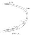
- FIG. 6shows a unitary embodiment
- lead impedancemay include several components.
- lead impedancemay include impedance of a connection between circuitry and a first electrode, first electrode impedance, interface impedance between the first electrode and patient tissue, patient impedance between the first electrode and a second electrode, interface impedance between patient tissue and the second electrode, second electrode impedance, and/or the impedance of a connection between circuitry and the second electrode.
- Typical values for lead impedancewill vary from one device and implantation method to another. For example, conventional devices have heretofore made use of epicardial, transvenous, and/or cardiac electrodes. Some new devices will make use of subcutaneous electrodes having different spacings and crossing different tissue components.
- the present inventionwill be incorporated into an implantable cardioverter-defibrillator (ICD).
- ICDimplantable cardioverter-defibrillator
- Other embodimentsmay also be used or incorporated into pacemakers or other electrical stimulus supplying devices. While the following generally discusses lead impedance, it is also contemplated that impedance between any two electrodes of an implantable stimulus system may be measured, for example, in a unitary stimulus system.
- One example in the cardiac contextis that disclosed in commonly assigned U.S. Pat. No. 6,647,292, the disclosure of which is incorporated herein by reference.
- FIG. 2is a block schematic for an implantable cardiac stimulus device that is configured as an ICD.
- the ICD 50typically includes batteries 52 that power a control block 54 , which may include a microcontroller, logic, or the like.
- the control block 54is coupled to a charger 56 that is used to relay power from the batteries 52 to energy storage 58 .
- Energy storage 58is a temporary energy storage system that may include one or more capacitors.
- the charger 56is used to step up the voltage supplied by the batteries 52 (typically in the range of a few volts) to a voltage more suitable for defibrillation (often on the order of hundreds of volts), and store this energy at the higher voltage in the energy storage 58 .
- the energy storage 58is electrically connected to coupling circuitry 60 that is used to connect with the patient 62 .
- Sensing circuitry 64is also connected to the coupling circuitry 60 , and is used by the control block 54 to determine whether defibrillation is needed.
- the sensing circuitry 64may include suitable circuitry and circuit elements for amplifying, filtering, and/or analysis of cardiac signals. Not shown, though often included, is additional circuitry used to discharge any excess charge on the energy storage 58 , for example, after delivery of a stimulus.
- the typical operation of an ICD for defibrillationincludes the following. First, the control block 54 determines, using the sensing circuitry 64 , that defibrillation is needed due to the occurrence of a malignant cardiac condition. Next, the control block 54 causes the charger 56 to begin charging the energy storage 58 . Once the energy storage 58 is charged to a desired level or for a predetermined time, the control block 54 causes the coupling circuitry 60 to discharge the energy storage 58 to the patient 62 .
- the present inventionmay be incorporated into an ICD, into an implantable pacing device, or into a hybrid device having both ICD and pacemaker features.
- the delivered stimulus energywill be much lower than that of an ICD, such that the charger 56 and/or energy storage 58 shown in FIG. 2 may be omitted, simplified, or bypassed.
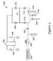
- FIG. 3is a schematic diagram for an illustrative embodiment.
- the illustrative embodimentis shown in the form of an ICD-pacemaker hybrid device having an H-bridge configuration.
- the circuit 100includes a battery 102 coupled via a charger 104 to a capacitance shown as power capacitor 106 .
- the power capacitor 106may be a single device or may be any suitable configuration of several capacitors and/or other suitable devices.
- the power capacitor 106is coupled to an H-bridge having a first high side switch 108 and a second high side switch 110 which couple to a patient via electrodes, with the patient shown schematically as a resistor P.
- the H-bridgefurther includes low side switches 112 , 114 .
- the switches 108 , 110 , 112 , 114may take any suitable form such as, for example, silicon controlled rectifiers (SCR), insulated gate bipolar transistors (IGBT), or MOSFET devices.
- SCRsilicon controlled rectifiers
- IGBTinsulated gate bipolar transistors
- MOSFET devicesMOSFET devices.
- transistors, rather than SCR devicesare used for the low side switches 112 , 114 to provide for a constant current control during pacing functions and/or fibrillation inducing device efficacy testing.
- the circuit 100further includes three discharge legs.
- a first legincludes a testing resistor 116 .
- a second legincludes a nonlinear device 118 adapted for use in defibrillation.
- the nonlinear device 118may be a MOSFET switch. In other embodiments, the nonlinear device 118 may be a different type of switch, or it may be a diode or any other device allowing for high current throughput to ground.
- a third legincludes both a switch and a resistor and is referred to herein as a constant current leg 120 .
- the constant current leg 120can be used to provide a feedback circuit that may be used to make the low side switches 112 , 114 functional for current controlling circuits, as set forth in U.S. Pat. No. 6,952,608, the disclosure of which is incorporated herein by reference.
- Each of the three discharge legsconnects together at node 122 which is shown connected to a lead impedance testing circuit.
- a switch 124 in combination with a capacitor 126makes a sample and hold circuit, the output of which is coupled into an analog-to-digital converter 128 that provides a digital signal indicative of a sampled voltage to control block 130 .
- the converter 128 and control block 130may both be part of a microcontroller.
- circuit 100During operation, several modes are available for circuit 100 .
- a defibrillation modehigh side switches 108 , 110 remain open while the power capacitor 106 is charged from the battery 102 by charger 104 to a stimulation level that may be set to a suitable level; typical levels range into the hundreds of volts but vary from device to device.
- a high side switch and a low side switcheach close to allow stimulus to reach the patient P, with delivery combinations including switches 108 / 114 or switches 110 / 112 .
- the defibrillation currentthen reaches node 122 , where it passes primarily through the non-linear device 118 .
- the non-linear device 118is a switch, it may be closed, grounding node 122 . If the non-linear device 118 is a diode, then node 122 is held at the diode threshold voltage, such that some current may pass through one of the other legs while the major portion of current passes through the non-linear device. For example, if a one-amp pulse of current is applied for defibrillation and the resistance from node 122 to ground is 33 ohms and the non-linear device is a diode having a 0.7 V threshold, approximately 21 mA of current goes through the resistor, while the rest of the current goes through the non-linear device.
- the switch in the constant current leg 120is closed.
- Feedbackmay be used to control current by adjusting the base voltage supplied to switches 112 , 114 if such switches are supplied as IGBT devices, or the gate voltage if such switches are MOSFET devices.
- the switch in the constant current leg 120is open. If a switch is used as non-linear device 118 , that switch remains open as well. As further explained below, if the voltages used, particularly the voltage at node 122 , remain low enough, a diode used as non-linear device 118 will act as an open circuit.
- the capacitor 106is charged to a predetermined testing level using the battery 102 and charger 104 . The testing level may be selected to avoid providing a stimulus to the patient that is noticed by the patient or which modifies cardiac function. When the testing level is reached, an appropriate combination of H-bridge switches is closed (either switches 108 / 114 or switches 110 / 112 ) to apply the testing pulse to the patient P.
- sampling switch 124is closed, causing capacitor 126 to sample the voltage at node 122 .
- the sampling switch 124is opened, holding the sampled voltage.
- Converter 128is used to convert the sampled voltage to a digital signal for use by the control 130 .
- the patient resistance Pis simplified for the purpose of illustration, as it may include impedances that are resistive and reactive, and includes any impedance encountered when current goes from the circuit 100 through lines connecting (sometimes through leads) to the electrodes, which in turn couple to and through patient tissue.
- R Lis the lead impedance
- R Tis the testing resistor 116 resistance
- V Tis the applied testing voltage
- V 122is the voltage sampled at node 122 .
- the applied voltage V Tis 3 Volts
- the sampled voltageis 0.48 Volts
- R Tbeing 33 ohms
- the above numerical examplealso shows that a diode having a threshold voltage of 0.6-0.7 volts, for example, could be used as the non-linear device 118 , since the sampled voltage at node 122 is less than the diode threshold.
- the inclusion of a number of switches in the circuitrymeans that there may be some difficulty in exactly specifying the actual impedance.
- the use of a capacitor to provide the voltage pulsemeans that the pulse itself degrades with time, while the use of a capacitor to sample the voltage means there is some time constant involved in the sampling method, which may also pose difficulties in exact calculation.
- an expected range of impedancesis defined, such as a range between 75-225 ohms for a subcutaneous device, this range may be used to determine whether the device is likely operating correctly.
- the “on-time” of the applied pulse used for testing lead impedanceis kept quite short, for example, less than 20 milliseconds. This may be the case, for example, to prevent stimulation of the patient's muscles during lead impedance testing.
- the applied voltagemay be modeled as a constant, as there is little time to drain the stored voltage on the power capacitor.
- the charging circuitrymay be maintained in an active state during application of the testing pulse, preventing significant degradation of the stored voltage.
- a number of test impedancesmay be used prior to insertion to define acceptable sensed voltage ranges.
- a header and lead assemblymay be coupled to a given canister, and several resistors may be placed between the electrodes prior to insertion for the purpose of testing the device ranges. This may allow calibration of the device for various purposes including lead impedance measurement.
- a test with a known resistormay be directed by a programmer prior to insertion of the device, and the programmer may then communicate the “actual” impedance of the known resistor to the implantable device, allowing the implantable device to determine an acceptable range based on its internal measurement.
- a testing setis provided prior to implantation. More specifically, a device as shown in FIG. 1 may be provided such that the header, which connects the lead 16 to the canister 12 , is attachable to the canister 12 prior to implantation. Before implantation and before attachment of the lead 16 and header, a set of testing devices having known impedances may be used to initialize the device. Thus the canister 12 may be coupled to an impedance mimicking a minimum expected impedance for testing purposes, and later coupled to an impedance mimicking a maximum expected impedance for testing purposes. The testing operation may be performed while in each of the configurations, and the sampled voltages noted as corresponding to minimum and maximum lead impedance.
- Each of the above methodsprovides a form of determining whether the lead impedance is acceptable without being an exhaustive list of ways for checking the acceptability of lead impedance.
- FIG. 4shows, in block diagram form, an illustrative method embodiment.
- the illustrative methoduses reference numerals from FIG. 3 .
- the systemis in a state as shown at 200 wherein the H-bridge switches are open.
- the power capacitoris charged, as shown at 202 , to a test voltage level.
- the test voltagemay be any appropriate voltage, preferably (though not necessarily) chosen such that the patient will not be aware that testing is occurring and/or such that cardiac function of the patient is uninterrupted.
- Any bypass switchesare then opened, as shown at 204 .
- the methodmay take one of two paths.
- the methodmay close a first pair of H-bridge switches, as shown at 206 A.
- a sampleis taken by closing and opening a sampling switch, as shown at 208 A, after which the H-bridge switches are again opened, as shown at 210 A.
- a second pair of H-bridge switchesare opened, as shown at 206 B, a sample is taken at 208 B, and the H-bridge switches are again opened, as shown at 210 B.
- the sampled voltageis checked, as shown at 212 .
- the lead impedancemay then be determined, as shown at 214 , as being either acceptable or unacceptable.
- the methodends here, as shown at 216 .
- the methodwill restart, as shown at 218 , to allow for testing on a different branch. For example, if a first time through the method follows steps 206 A, 208 A and 210 A, the method may recycle at 218 and follow steps 206 B, 208 B and 210 B the next time. This allows for not only checking lead impedance but also making certain that each of the H-bridge switches is operating in an acceptable fashion. Further, the optional step of testing the circuit in both “directions” allows the method to subtract any electrode polarization voltage that could contribute an error term to the calculation of lead impedance if only a single measurement is used.
- FIG. 5illustrates another method embodiment in block form. From a start block, the method includes charging the power capacitor to a test voltage, as shown at 300 . Next, the test voltage is delivered to the patient through a test resistor, as shown at 302 . The test resistor voltage is sampled while the voltage is being delivered, as shown at 304 . Next, it is determined whether the lead impedance is acceptable, as shown at 306 . The method of checking lead impedance then ends. If the lead impedance is not acceptable, an error flag may be set by the system controller, or other corrective or annotative action may be taken.
- the sampling stepmay be performed across a very short interval. In such embodiments, this prevents degradation of the applied voltage from the power capacitor, while also avoiding patient stimulation. If the power capacitor discharges too much during testing, the reading across the test resistor may be reduced due to discharge, rather than attenuation, potentially causing confusion and/or leading to an error. In some embodiments, this effect is avoided by using a test interval shorter than the RC time constant of the power capacitor and test resistor only. In another embodiment, the sampling and/or test interval has a duration less than half the RC time constant of the power capacitor and test resistor only.
- a unitary systemallows for testing impedance between two electrodes both disposed on the canister or housing of an implantable cardiac stimulation device.
- FIG. 6shows a unitary system 400 having electrodes 402 , 404 , 406 , 408 all disposed on a unitary canister, in this embodiment without a separate lead. Impedance may be tested between any of the electrodes 402 , 404 , 406 , 408 .
- the device as shown in FIG. 6may be implanted as described, for example, in U.S. Pat. No. 6,647,292.
Landscapes
- Health & Medical Sciences (AREA)
- Cardiology (AREA)
- Heart & Thoracic Surgery (AREA)
- Life Sciences & Earth Sciences (AREA)
- Radiology & Medical Imaging (AREA)
- Nuclear Medicine, Radiotherapy & Molecular Imaging (AREA)
- Biomedical Technology (AREA)
- Engineering & Computer Science (AREA)
- Animal Behavior & Ethology (AREA)
- General Health & Medical Sciences (AREA)
- Public Health (AREA)
- Veterinary Medicine (AREA)
- Biophysics (AREA)
- Electrotherapy Devices (AREA)
Abstract
Description
(RL+RT)/RT=VT/V122
Where RLis the lead impedance, RTis the
Claims (11)
Priority Applications (2)
| Application Number | Priority Date | Filing Date | Title |
|---|---|---|---|
| US11/525,497US7877139B2 (en) | 2006-09-22 | 2006-09-22 | Method and device for implantable cardiac stimulus device lead impedance measurement |
| PCT/US2007/079118WO2008036869A1 (en) | 2006-09-22 | 2007-09-21 | Method and device for implantable cardiac stimulus device lead impedance measurement |
Applications Claiming Priority (1)
| Application Number | Priority Date | Filing Date | Title |
|---|---|---|---|
| US11/525,497US7877139B2 (en) | 2006-09-22 | 2006-09-22 | Method and device for implantable cardiac stimulus device lead impedance measurement |
Publications (2)
| Publication Number | Publication Date |
|---|---|
| US20080077189A1 US20080077189A1 (en) | 2008-03-27 |
| US7877139B2true US7877139B2 (en) | 2011-01-25 |
Family
ID=39064403
Family Applications (1)
| Application Number | Title | Priority Date | Filing Date |
|---|---|---|---|
| US11/525,497Active2029-11-25US7877139B2 (en) | 2006-09-22 | 2006-09-22 | Method and device for implantable cardiac stimulus device lead impedance measurement |
Country Status (2)
| Country | Link |
|---|---|
| US (1) | US7877139B2 (en) |
| WO (1) | WO2008036869A1 (en) |
Cited By (10)
| Publication number | Priority date | Publication date | Assignee | Title |
|---|---|---|---|---|
| US20100324619A1 (en)* | 2009-06-23 | 2010-12-23 | Medtronic, Inc. | Constant current pacing apparatus with protection from high voltage pulses |
| US8972005B2 (en) | 2013-03-12 | 2015-03-03 | Medtronic, Inc. | Subthreshold lead impedance measurement for subcutaneous device |
| US9956422B2 (en) | 2014-04-24 | 2018-05-01 | Medtronic, Inc. | Therapy delivery methods and circuits for an implantable medical device |
| US10625087B2 (en) | 2014-04-24 | 2020-04-21 | Medtronic, Inc. | Therapy delivery methods and circuits for an implantable medical device |
| US11717695B2 (en) | 2020-02-13 | 2023-08-08 | Cardiac Pacemakers, Inc. | High voltage therapy system with current control |
| US11745023B2 (en) | 2020-03-12 | 2023-09-05 | Cardiac Pacemakers, Inc. | High voltage therapy system with low side control |
| US11826577B2 (en) | 2021-02-25 | 2023-11-28 | Medtronic, Inc. | Impedance measurement circuit architecture |
| US11931592B2 (en) | 2020-02-13 | 2024-03-19 | Cardiac Pacemakers, Inc. | Output circuitry for multiple-therapy implantable devices |
| US12036417B2 (en) | 2020-02-13 | 2024-07-16 | Cardiac Pacemakers, Inc. | High voltage therapy system with transformer primary current control |
| US12440694B2 (en) | 2024-02-13 | 2025-10-14 | Cardiac Pacemakers, Inc. | Output circuitry for multiple-therapy implantable devices |
Families Citing this family (25)
| Publication number | Priority date | Publication date | Assignee | Title |
|---|---|---|---|---|
| US20090132009A1 (en)* | 2007-11-21 | 2009-05-21 | Medtronic, Inc. | Determination of stimulation output capabilities throughout power source voltage range |
| US7818060B2 (en) | 2008-10-31 | 2010-10-19 | Medtronic, Inc. | Determination of stimulation output capabilities throughout power source voltage range |
| US8219196B2 (en) | 2008-10-31 | 2012-07-10 | Medtronic, Inc. | Determination of stimulation output capabilities throughout power source voltage range |
| US8401646B2 (en) | 2010-10-21 | 2013-03-19 | Medtronic, Inc. | Method and apparatus to determine the relative energy expenditure for a plurality of pacing vectors |
| CA2831062A1 (en) | 2011-01-28 | 2012-08-02 | Stimwave Technologies Incorporated | Neural stimulator system |
| US12115374B2 (en) | 2011-01-28 | 2024-10-15 | Curonix Llc | Microwave field stimulator |
| WO2012138782A1 (en) | 2011-04-04 | 2012-10-11 | Stimwave Technologies Incorporated | Implantable lead |
| US9220897B2 (en) | 2011-04-04 | 2015-12-29 | Micron Devices Llc | Implantable lead |
| CN104080509B (en) | 2011-07-29 | 2017-09-08 | 米克伦设备有限责任公司 | Remote control for power or polarity selection of neurostimulators |
| WO2013025632A1 (en)* | 2011-08-12 | 2013-02-21 | Stimwave Technologies Incorporated | Microwave field stimulator |
| CA2848998A1 (en) | 2011-09-15 | 2013-03-21 | Stimwave Technologies Incorporated | Relay module for implant |
| US9199087B2 (en) | 2011-11-21 | 2015-12-01 | Medtronic, Inc. | Apparatus and method for selecting a preferred pacing vector in a cardiac resynchronization device |
| US9254393B2 (en) | 2012-12-26 | 2016-02-09 | Micron Devices Llc | Wearable antenna assembly |
| CN110665114B (en) | 2014-05-12 | 2022-12-06 | 斯蒂维科技公司 | Remote RF power system with small size transmit antenna |
| US10874451B2 (en) | 2016-02-29 | 2020-12-29 | Pulse Biosciences, Inc. | High-voltage analog circuit pulser and pulse generator discharge circuit |
| US10548665B2 (en) | 2016-02-29 | 2020-02-04 | Pulse Biosciences, Inc. | High-voltage analog circuit pulser with feedback control |
| US20170319851A1 (en)* | 2016-05-06 | 2017-11-09 | Pulse Biosciences, Inc. | Low-voltage impedance check pulse generator |
| WO2017200954A1 (en) | 2016-05-16 | 2017-11-23 | Pulse Biosciences, Inc. | Pulse applicator |
| US10543357B2 (en) | 2016-09-19 | 2020-01-28 | Pulse Biosciences, Inc. | High voltage connectors for pulse generators |
| US10946193B2 (en) | 2017-02-28 | 2021-03-16 | Pulse Biosciences, Inc. | Pulse generator with independent panel triggering |
| US10857347B2 (en) | 2017-09-19 | 2020-12-08 | Pulse Biosciences, Inc. | Treatment instrument and high-voltage connectors for robotic surgical system |
| AU2019215179B2 (en) | 2018-02-01 | 2024-11-07 | Curonix Llc | Systems and methods to sense stimulation electrode tissue impedance |
| KR101957154B1 (en)* | 2018-04-02 | 2019-07-04 | 주식회사메디아나 | Defibrillator drive method capable of early defibrillation and its defibrillator |
| US11571569B2 (en) | 2019-02-15 | 2023-02-07 | Pulse Biosciences, Inc. | High-voltage catheters for sub-microsecond pulsing |
| US11305128B1 (en)* | 2019-07-09 | 2022-04-19 | Avive Solutions, Inc. | Defibrillator discharge testing |
Citations (191)
| Publication number | Priority date | Publication date | Assignee | Title |
|---|---|---|---|---|
| US3653387A (en) | 1970-05-08 | 1972-04-04 | Cardiac Electronics Inc | Protector circuit for cardiac apparatus |
| US3710374A (en) | 1970-03-16 | 1973-01-09 | Wester Instr Inc | Dual-slope and analog-to-digital converter wherein two analog input signals are selectively integrated with respect to time |
| US3911925A (en) | 1974-05-23 | 1975-10-14 | Jr Joe B Tillery | Ear trimming forceps |
| US4030509A (en) | 1975-09-30 | 1977-06-21 | Mieczyslaw Mirowski | Implantable electrodes for accomplishing ventricular defibrillation and pacing and method of electrode implantation and utilization |
| US4157720A (en) | 1977-09-16 | 1979-06-12 | Greatbatch W | Cardiac pacemaker |
| US4164946A (en) | 1977-05-27 | 1979-08-21 | Mieczyslaw Mirowski | Fault detection circuit for permanently implanted cardioverter |
| US4184493A (en) | 1975-09-30 | 1980-01-22 | Mieczyslaw Mirowski | Circuit for monitoring a heart and for effecting cardioversion of a needy heart |
| US4191942A (en) | 1978-06-08 | 1980-03-04 | National Semiconductor Corporation | Single slope A/D converter with sample and hold |
| US4210149A (en) | 1978-04-17 | 1980-07-01 | Mieczyslaw Mirowski | Implantable cardioverter with patient communication |
| USRE30387E (en) | 1972-03-17 | 1980-08-26 | Medtronic, Inc. | Automatic cardioverting circuit |
| US4223678A (en) | 1978-05-03 | 1980-09-23 | Mieczyslaw Mirowski | Arrhythmia recorder for use with an implantable defibrillator |
| US4248237A (en) | 1978-03-07 | 1981-02-03 | Needle Industries Limited | Cardiac pacemakers |
| US4254775A (en) | 1979-07-02 | 1981-03-10 | Mieczyslaw Mirowski | Implantable defibrillator and package therefor |
| US4291707A (en) | 1979-04-30 | 1981-09-29 | Mieczyslaw Mirowski | Implantable cardiac defibrillating electrode |
| US4300567A (en) | 1980-02-11 | 1981-11-17 | Mieczyslaw Mirowski | Method and apparatus for effecting automatic ventricular defibrillation and/or demand cardioversion through the means of an implanted automatic defibrillator |
| US4314095A (en) | 1979-04-30 | 1982-02-02 | Mieczyslaw Mirowski | Device and method for making electrical contact |
| US4375817A (en) | 1979-07-19 | 1983-03-08 | Medtronic, Inc. | Implantable cardioverter |
| US4402322A (en) | 1981-03-25 | 1983-09-06 | Medtronic, Inc. | Pacer output circuit |
| US4407288A (en) | 1981-02-18 | 1983-10-04 | Mieczyslaw Mirowski | Implantable heart stimulator and stimulation method |
| EP0095727A1 (en) | 1982-06-01 | 1983-12-07 | Purdue Research Foundation | Method and apparatus for inserting a defibrillator electrode and defibrillator electrode |
| US4424818A (en) | 1982-02-18 | 1984-01-10 | Medtronic, Inc. | Electrical lead and insertion tool |
| US4450527A (en) | 1982-06-29 | 1984-05-22 | Bomed Medical Mfg. Ltd. | Noninvasive continuous cardiac output monitor |
| US4548209A (en) | 1984-02-06 | 1985-10-22 | Medtronic, Inc. | Energy converter for implantable cardioverter |
| US4567900A (en) | 1984-06-04 | 1986-02-04 | Moore J Paul | Internal deployable defibrillator electrode |
| US4595009A (en) | 1984-02-06 | 1986-06-17 | Medtronic, Inc. | Protection circuit for implantable cardioverter |
| US4602637A (en) | 1983-01-11 | 1986-07-29 | Siemens Aktiengesellschaft | Heart pacemaker system |
| US4603705A (en) | 1984-05-04 | 1986-08-05 | Mieczyslaw Mirowski | Intravascular multiple electrode unitary catheter |
| US4693253A (en) | 1981-03-23 | 1987-09-15 | Medtronic, Inc. | Automatic implantable defibrillator and pacer |
| US4727877A (en) | 1984-12-18 | 1988-03-01 | Medtronic, Inc. | Method and apparatus for low energy endocardial defibrillation |
| US4750494A (en) | 1981-05-12 | 1988-06-14 | Medtronic, Inc. | Automatic implantable fibrillation preventer |
| US4765341A (en) | 1981-06-22 | 1988-08-23 | Mieczyslaw Mirowski | Cardiac electrode with attachment fin |
| US4768512A (en) | 1986-05-13 | 1988-09-06 | Mieczyslaw Mirowski | Cardioverting system and method with high-frequency pulse delivery |
| US4800883A (en) | 1986-04-02 | 1989-01-31 | Intermedics, Inc. | Apparatus for generating multiphasic defibrillation pulse waveform |
| US4830005A (en) | 1987-07-23 | 1989-05-16 | Siemens-Pacesetter, Inc. | Disposable in-package load test element for pacemakers |
| EP0316616A2 (en) | 1987-11-19 | 1989-05-24 | Siemens Aktiengesellschaft | Analog-digital converter |
| EP0347353A1 (en) | 1988-06-15 | 1989-12-20 | ATESYS, société anonyme | High performance defibrillator with several electrodes outside the heart |
| US4944300A (en) | 1987-04-28 | 1990-07-31 | Sanjeev Saksena | Method for high energy defibrillation of ventricular fibrillation in humans without a thoracotomy |
| US5014697A (en)* | 1986-05-14 | 1991-05-14 | Ventritex | Programmable defibrillator |
| US5044374A (en) | 1987-06-18 | 1991-09-03 | Medtronic, Inc. | Medical electrical lead |
| US5105826A (en) | 1990-10-26 | 1992-04-21 | Medtronic, Inc. | Implantable defibrillation electrode and method of manufacture |
| US5105810A (en) | 1990-07-24 | 1992-04-21 | Telectronics Pacing Systems, Inc. | Implantable automatic and haemodynamically responsive cardioverting/defibrillating pacemaker with means for minimizing bradycardia support pacing voltages |
| US5109842A (en) | 1990-09-24 | 1992-05-05 | Siemens Pacesetter, Inc. | Implantable tachyarrhythmia control system having a patch electrode with an integrated cardiac activity system |
| US5129392A (en) | 1990-12-20 | 1992-07-14 | Medtronic, Inc. | Apparatus for automatically inducing fibrillation |
| US5133353A (en) | 1990-04-25 | 1992-07-28 | Cardiac Pacemakers, Inc. | Implantable intravenous cardiac stimulation system with pulse generator housing serving as optional additional electrode |
| US5144946A (en) | 1991-08-05 | 1992-09-08 | Siemens Pacesetter, Inc. | Combined pacemaker substrate and electrical interconnect and method of assembly |
| US5163428A (en)* | 1990-10-11 | 1992-11-17 | Ventritex, Inc. | Implantable cardiac defibrillator with current leakage detecting means |
| EP0518599A2 (en) | 1991-06-14 | 1992-12-16 | Telectronics N.V. | Implantable pacemaker/cardioverter/defibrillator device and method incorporating multiple bradycardia support pacing rates |
| US5184616A (en) | 1991-10-21 | 1993-02-09 | Telectronics Pacing Systems, Inc. | Apparatus and method for generation of varying waveforms in arrhythmia control system |
| US5191901A (en) | 1991-08-29 | 1993-03-09 | Mieczyslaw Mirowski | Controlled discharge defibrillation electrode |
| US5201865A (en)* | 1991-10-28 | 1993-04-13 | Medtronic, Inc. | Medical lead impedance measurement system |
| US5203348A (en) | 1990-06-06 | 1993-04-20 | Cardiac Pacemakers, Inc. | Subcutaneous defibrillation electrodes |
| US5215081A (en) | 1989-12-28 | 1993-06-01 | Telectronics Pacing Systems, Inc. | Method and device for measuring subthreshold defibrillation electrode resistance and providing a constant energy shock delivery |
| US5230337A (en) | 1990-06-06 | 1993-07-27 | Cardiac Pacemakers, Inc. | Process for implanting subcutaneous defibrillation electrodes |
| WO1993019809A1 (en) | 1992-04-06 | 1993-10-14 | Angemed, Inc. | System for treatment of ventricular tachycardia using a far-field pulse series |
| US5255692A (en) | 1992-09-04 | 1993-10-26 | Siemens Aktiengesellschaft | Subcostal patch electrode |
| US5261400A (en) | 1992-02-12 | 1993-11-16 | Medtronic, Inc. | Defibrillator employing transvenous and subcutaneous electrodes and method of use |
| US5300106A (en) | 1991-06-07 | 1994-04-05 | Cardiac Pacemakers, Inc. | Insertion and tunneling tool for a subcutaneous wire patch electrode |
| US5313953A (en) | 1992-01-14 | 1994-05-24 | Incontrol, Inc. | Implantable cardiac patient monitor |
| US5331966A (en) | 1991-04-05 | 1994-07-26 | Medtronic, Inc. | Subcutaneous multi-electrode sensing system, method and pacer |
| US5366496A (en) | 1993-04-01 | 1994-11-22 | Cardiac Pacemakers, Inc. | Subcutaneous shunted coil electrode |
| EP0627237A1 (en) | 1991-06-26 | 1994-12-07 | Hector Osvaldo Trabucco | Pacemaker |
| US5376104A (en) | 1992-02-07 | 1994-12-27 | Nihon Kohden Corporation | Defibrillator with electrocardiogram monitor |
| US5376103A (en) | 1992-03-19 | 1994-12-27 | Angeion Corporation | Electrode system for implantable defibrillator |
| US5391200A (en) | 1992-09-30 | 1995-02-21 | Cardiac Pacemakers, Inc. | Defibrillation patch electrode having conductor-free resilient zone for minimally invasive deployment |
| EP0641573A2 (en) | 1993-08-31 | 1995-03-08 | Ventritex, Inc. | Method and apparatus for phase related cardiac defibrillation |
| US5405363A (en) | 1991-03-15 | 1995-04-11 | Angelon Corporation | Implantable cardioverter defibrillator having a smaller displacement volume |
| US5411547A (en) | 1993-08-09 | 1995-05-02 | Pacesetter, Inc. | Implantable cardioversion-defibrillation patch electrodes having means for passive multiplexing of discharge pulses |
| US5411539A (en) | 1993-08-31 | 1995-05-02 | Medtronic, Inc. | Active can emulator and method of use |
| US5413591A (en) | 1992-02-26 | 1995-05-09 | Angeion Corporation | Current truncated waveform defibrillator |
| US5423326A (en) | 1991-09-12 | 1995-06-13 | Drexel University | Apparatus and method for measuring cardiac output |
| US5425748A (en)* | 1993-08-05 | 1995-06-20 | Ventritex, Inc. | Method and apparatus for cardiac defibrillation |
| US5439485A (en) | 1993-09-24 | 1995-08-08 | Ventritex, Inc. | Flexible defibrillation electrode of improved construction |
| US5453698A (en) | 1994-09-28 | 1995-09-26 | Ventirtex, Inc. | Method and system for testing an implantable defibrillator output stage and high voltage lead integrity |
| EP0677301A1 (en) | 1994-04-14 | 1995-10-18 | Pacesetter AB | Electrode apparatus with a variable distance between the electrodes |
| US5476503A (en) | 1994-03-28 | 1995-12-19 | Pacesetter, Inc. | Sense array intelligent patch lead for an implantable defibrillator and method |
| US5509928A (en) | 1995-03-02 | 1996-04-23 | Pacesetter, Inc. | Internally supported self-sealing septum |
| US5509923A (en) | 1989-08-16 | 1996-04-23 | Raychem Corporation | Device for dissecting, grasping, or cutting an object |
| US5531766A (en) | 1995-01-23 | 1996-07-02 | Angeion Corporation | Implantable cardioverter defibrillator pulse generator kite-tail electrode system |
| US5531765A (en) | 1990-12-18 | 1996-07-02 | Ventritex, Inc. | Method and apparatus for producing configurable biphasic defibrillation waveforms |
| US5534022A (en) | 1994-11-22 | 1996-07-09 | Ventritex, Inc. | Lead having an integrated defibrillation/sensing electrode |
| US5534019A (en) | 1994-12-09 | 1996-07-09 | Ventritex, Inc. | Cardiac defibrillator with case that can be electrically active or inactive |
| US5549646A (en) | 1994-12-06 | 1996-08-27 | Pacesetter, Inc. | Periodic electrical lead intergrity testing system and method for implantable cardiac stimulating devices |
| US5591213A (en) | 1993-05-18 | 1997-01-07 | Heartstream, Inc. | Defibrillator system condition indictator |
| US5597956A (en) | 1994-08-24 | 1997-01-28 | Murata Manufacturing Co., Ltd. | Capacitor type acceleration sensor |
| US5601607A (en) | 1992-03-19 | 1997-02-11 | Angeion Corporation | Implantable cardioverter defibrillator housing plated electrode |
| US5607455A (en) | 1995-05-25 | 1997-03-04 | Intermedics, Inc. | Method and apparatus for automatic shock electrode enabling |
| US5618287A (en) | 1994-01-28 | 1997-04-08 | Thomas J. Fogarty | Methods of surgically implanting a defibrillator electrode within a patient |
| US5620477A (en) | 1994-03-31 | 1997-04-15 | Ventritex, Inc. | Pulse generator with case that can be active or inactive |
| US5643328A (en) | 1996-07-19 | 1997-07-01 | Sulzer Intermedics Inc. | Implantable cardiac stimulation device with warning system having elongated stimulation electrode |
| US5645586A (en) | 1994-07-08 | 1997-07-08 | Ventritex, Inc. | Conforming implantable defibrillator |
| US5658317A (en) | 1995-08-14 | 1997-08-19 | Cardiac Pacemakers, Inc. | Threshold templating for digital AGC |
| US5658321A (en) | 1995-06-09 | 1997-08-19 | Ventritex, Inc. | Conductive housing for implantable cardiac device |
| US5658319A (en) | 1993-12-13 | 1997-08-19 | Angeion Corporation | Implantable cardioverter defibrillator having a high voltage capacitor |
| WO1997029802A2 (en) | 1996-02-20 | 1997-08-21 | Advanced Bionics Corporation | Improved implantable microstimulator and systems employing the same |
| EP0536873B1 (en) | 1991-10-07 | 1997-09-17 | Telectronics N.V. | Apparatus for arrhythmia induction in arrhythmia control system |
| US5674260A (en) | 1996-02-23 | 1997-10-07 | Pacesetter, Inc. | Apparatus and method for mounting an activity sensor or other component within a pacemaker using a contoured hybrid lid |
| US5690683A (en) | 1995-06-19 | 1997-11-25 | Cardiac Pacemakers, Inc. | After potential removal in cardiac rhythm management device |
| US5697953A (en) | 1993-03-13 | 1997-12-16 | Angeion Corporation | Implantable cardioverter defibrillator having a smaller displacement volume |
| US5713926A (en) | 1990-04-25 | 1998-02-03 | Cardiac Pacemakers, Inc. | Implantable intravenous cardiac stimulation system with pulse generator housing serving as optional additional electrode |
| US5722997A (en) | 1996-09-17 | 1998-03-03 | Sulzer Intermedics Inc. | Method and apparatus for cardiac impedance sensing |
| US5741311A (en) | 1996-06-27 | 1998-04-21 | Medtronic, Inc. | Implantable medical device system with method for determining lead condition |
| US5755742A (en) | 1996-11-05 | 1998-05-26 | Medtronic, Inc. | Cardioversion/defibrillation lead impedance measurement system |
| DE29801807U1 (en) | 1997-02-04 | 1998-06-04 | Mathar, Ralph, Humble | Device for use in surgical interventions, in particular in bypass operations |
| WO1998025349A1 (en) | 1996-12-03 | 1998-06-11 | Microchip Technology Incorporated | Slope analog-to-digital converter with ramp initiated prior to counter |
| US5766226A (en) | 1996-12-09 | 1998-06-16 | Angeion Corporation | Switched discharge pathways for ICD having multiple output capacitors |
| US5776169A (en) | 1997-04-28 | 1998-07-07 | Sulzer Intermedics Inc. | Implantable cardiac stimulator for minimally invasive implantation |
| US5814088A (en) | 1997-03-26 | 1998-09-29 | Sulzer Intermedics Inc. | Cardiac stimulator with lead failure detector and warning system |
| US5814090A (en) | 1995-06-07 | 1998-09-29 | Angeion Corporation | Implantable medical device having heat-shrink conforming shield |
| US5836976A (en) | 1997-04-30 | 1998-11-17 | Medtronic, Inc. | Cardioversion energy reduction system |
| US5843132A (en) | 1996-10-07 | 1998-12-01 | Ilvento; Joseph P. | Self-contained, self-powered temporary intravenous pacing catheter assembly |
| WO1999003534A1 (en) | 1997-07-17 | 1999-01-28 | Cpr Medical, Inc. | Defibrillator/pacemaker |
| US5895414A (en) | 1996-04-19 | 1999-04-20 | Sanchez-Zambrano; Sergio | Pacemaker housing |
| US5904705A (en) | 1995-10-27 | 1999-05-18 | Angeion Corporation | Automatic battery-maintaining implantable cardioverter defibrillator and method for use |
| EP0917887A1 (en) | 1997-11-24 | 1999-05-26 | Pacesetter AB | A cardiac event detecting system for a heart stimulator |
| EP0923130A1 (en) | 1997-12-12 | 1999-06-16 | ELA MEDICAL (Société anonyme) | Electronic circuit, in particular for implantable active medical device, like a heart stimulator or defibrillator, and its manufacturing method |
| US5919222A (en) | 1998-01-06 | 1999-07-06 | Medtronic Inc. | Adjustable medical electrode lead |
| US5919211A (en) | 1996-06-27 | 1999-07-06 | Adams; Theodore P. | ICD power source using multiple single use batteries |
| US5925069A (en) | 1997-11-07 | 1999-07-20 | Sulzer Intermedics Inc. | Method for preparing a high definition window in a conformally coated medical device |
| WO1999037362A1 (en) | 1998-01-27 | 1999-07-29 | Vitatron Medical, B.V. | System for inducing tachycardia utilizing near field t-wave sensing |
| US5935154A (en) | 1997-01-24 | 1999-08-10 | Cardiac Pacemakers, Inc. | Implantable tissue stimulator incorporating deposited multilayer capacitor |
| US5941904A (en) | 1997-09-12 | 1999-08-24 | Sulzer Intermedics Inc. | Electromagnetic acceleration transducer for implantable medical device |
| US5957956A (en) | 1994-06-21 | 1999-09-28 | Angeion Corp | Implantable cardioverter defibrillator having a smaller mass |
| WO1999053991A1 (en) | 1998-04-23 | 1999-10-28 | Alza Corporation | Trocar for inserting implants |
| US6014586A (en) | 1995-11-20 | 2000-01-11 | Pacesetter, Inc. | Vertically integrated semiconductor package for an implantable medical device |
| US6016445A (en) | 1996-04-16 | 2000-01-18 | Cardiotronics | Method and apparatus for electrode and transthoracic impedance estimation |
| US6026325A (en) | 1998-06-18 | 2000-02-15 | Pacesetter, Inc. | Implantable medical device having an improved packaging system and method for making electrical connections |
| US6058328A (en) | 1996-08-06 | 2000-05-02 | Pacesetter, Inc. | Implantable stimulation device having means for operating in a preemptive pacing mode to prevent tachyarrhythmias and method thereof |
| EP1000634A1 (en) | 1998-11-10 | 2000-05-17 | Sulzer Osypka GmbH | Stimulation electrode for both defibrillation and pacing |
| WO2000041766A1 (en) | 1999-01-14 | 2000-07-20 | The Mower Family Chf Treatment Irrevocable Trust | Antitachycardial pacing |
| US6093173A (en) | 1998-09-09 | 2000-07-25 | Embol-X, Inc. | Introducer/dilator with balloon protection and methods of use |
| WO2000043065A1 (en) | 1999-01-25 | 2000-07-27 | Cardiac Pacemakers, Inc. | Cardiac rhythm management system with painless defibrillation lead impedance measurement |
| US6095987A (en) | 1996-04-17 | 2000-08-01 | Imagyn Medical Techonologies California, Inc. | Apparatus and methods of bioelectrical impedance analysis of blood flow |
| US6104954A (en)* | 1997-06-30 | 2000-08-15 | Blunsden; Christopher K. | High frequency lead testing apparatus in an implantable defibrillator |
| WO2000050120A1 (en) | 1999-02-25 | 2000-08-31 | St. Jude Medical Ab | Implantable tissue stimulating device |
| US6128531A (en) | 1998-04-01 | 2000-10-03 | Pacesetter, Inc. | Delivery of ICD shock capacitor energy via a controlled current source |
| USH1905H (en) | 1997-03-21 | 2000-10-03 | Medtronic, Inc. | Mechanism for adjusting the exposed surface area and position of an electrode along a lead body |
| US6144879A (en) | 1991-05-17 | 2000-11-07 | Gray; Noel Desmond | Heart pacemaker |
| US6144866A (en) | 1998-10-30 | 2000-11-07 | Medtronic, Inc. | Multiple sensor assembly for medical electric lead |
| US6148230A (en) | 1998-01-30 | 2000-11-14 | Uab Research Foundation | Method for the monitoring and treatment of spontaneous cardiac arrhythmias |
| US6161042A (en) | 1998-02-27 | 2000-12-12 | Cardiac Pacemakers, Inc. | Rate adaptive cardiac rhythm management device using transthoracic impedance |
| US6185450B1 (en) | 1998-01-26 | 2001-02-06 | Physio-Control Manufacturing Corporation | Digital sliding pole fast-restore for an electrocardiograph display |
| US6185458B1 (en)* | 1999-04-30 | 2001-02-06 | Agilent Technologies, Inc. | Reduced energy self test operation in a defibrillator |
| WO2001043649A1 (en) | 1999-12-17 | 2001-06-21 | Fogarty Thomas J | Method and device for use in minimally invasive approximation of muscle and other tissue |
| US6266567B1 (en) | 1999-06-01 | 2001-07-24 | Ball Semiconductor, Inc. | Implantable epicardial electrode |
| WO2001056166A2 (en) | 2000-01-28 | 2001-08-02 | Infineon Technologies Ag | Method and analog-to-digital converter for converting an analog voltage into an arithmetical value |
| US6278894B1 (en) | 1999-06-21 | 2001-08-21 | Cardiac Pacemakers, Inc. | Multi-site impedance sensor using coronary sinus/vein electrodes |
| US6317633B1 (en) | 1999-01-19 | 2001-11-13 | Medtronic, Inc. | Implantable lead functional status monitor and method |
| US6334071B1 (en) | 1999-06-07 | 2001-12-25 | Pacesetter, Inc. | Minute volume pacemakers that require only a single distal electrode |
| US6345198B1 (en) | 1998-01-23 | 2002-02-05 | Pacesetter, Inc. | Implantable stimulation system for providing dual bipolar sensing using an electrode positioned in proximity to the tricuspid valve and programmable polarity |
| WO2002022208A2 (en) | 2000-09-18 | 2002-03-21 | Cameron Health, Inc. | Subcutaneous only implantable cardioverter-defibrillator and optional pacer |
| WO2002024275A2 (en) | 2000-09-18 | 2002-03-28 | Cameron Health, Inc. | Unitary subcutaneous only implantable cardioverter-debribillator and optional pacer |
| US6411844B1 (en) | 1999-10-19 | 2002-06-25 | Pacesetter, Inc. | Fast recovery sensor amplifier circuit for implantable medical device |
| US6445951B1 (en) | 1999-10-12 | 2002-09-03 | Pacesetter, Inc. | Implantable cardiac stimulating device incorporating high frequency low amplitude lead impedance measurement |
| WO2002068046A1 (en) | 2000-11-03 | 2002-09-06 | Medtronic, Inc. | Mems switching circuit and method for an implantable medical device |
| US6473648B1 (en)* | 1998-05-08 | 2002-10-29 | Intermedics Inc. | Implantable cardiac stimulator with electrode-tissue interface characterization |
| WO2003018121A2 (en) | 2001-08-21 | 2003-03-06 | Medtronic,Inc. | Space-efficient implantable medical device assembly and manufacturing methods |
| WO2003053518A1 (en) | 2001-12-20 | 2003-07-03 | Koninklijke Philips Electronics N.V. | Method and apparatus for delivering defibrillation and pacing energy from a single power source |
| US6620186B2 (en) | 2000-05-25 | 2003-09-16 | International Business Machines Corporation | Method and system for medical lead impedance test |
| US6721600B2 (en) | 2000-01-19 | 2004-04-13 | Medtronic, Inc. | Implantable lead functional status monitor and method |
| US6754528B2 (en) | 2001-11-21 | 2004-06-22 | Cameraon Health, Inc. | Apparatus and method of arrhythmia detection in a subcutaneous implantable cardioverter/defibrillator |
| US6778860B2 (en) | 2001-11-05 | 2004-08-17 | Cameron Health, Inc. | Switched capacitor defibrillation circuit |
| US6788974B2 (en) | 2000-09-18 | 2004-09-07 | Cameron Health, Inc. | Radian curve shaped implantable cardioverter-defibrillator canister |
| US20040254611A1 (en) | 2003-06-02 | 2004-12-16 | Cameron Health, Inc. | Method and devices for performing cardiac waveform appraisal |
| US20040254613A1 (en) | 2001-11-21 | 2004-12-16 | Cameron Health, Inc. | Method for discriminating between ventricular and supraventricular arrhythmias |
| US6834204B2 (en) | 2001-11-05 | 2004-12-21 | Cameron Health, Inc. | Method and apparatus for inducing defibrillation in a patient using a T-shock waveform |
| US6856835B2 (en) | 2000-09-18 | 2005-02-15 | Cameron Health, Inc. | Biphasic waveform for anti-tachycardia pacing for a subcutaneous implantable cardioverter-defibrillator |
| US20050049644A1 (en) | 2001-11-21 | 2005-03-03 | Cameron Health, Inc. | Multiple electrode vectors for implantable cardiac treatment devices |
| US6865417B2 (en) | 2001-11-05 | 2005-03-08 | Cameron Health, Inc. | H-bridge with sensing circuit |
| US6866044B2 (en) | 2000-09-18 | 2005-03-15 | Cameron Health, Inc. | Method of insertion and implantation of implantable cardioverter-defibrillator canisters |
| DE202004016350U1 (en) | 2003-10-29 | 2005-03-17 | Corscience Gmbh & Co Kg | Defibrillator has capacitor energy source and H bridge with switches controlling patient current in response to values in pre and post patient impedance branches |
| US6927721B2 (en) | 2001-11-05 | 2005-08-09 | Cameron Health, Inc. | Low power A/D converter |
| US6937907B2 (en) | 2000-09-18 | 2005-08-30 | Cameron Health, Inc. | Subcutaneous electrode for transthoracic conduction with low-profile installation appendage and method of doing same |
| US6950705B2 (en) | 2000-09-18 | 2005-09-27 | Cameron Health, Inc. | Canister designs for implantable cardioverter-defibrillators |
| US6952610B2 (en) | 2000-09-18 | 2005-10-04 | Cameron Health, Inc. | Current waveforms for anti-tachycardia pacing for a subcutaneous implantable cardioverter- defibrillator |
| US6952608B2 (en) | 2001-11-05 | 2005-10-04 | Cameron Health, Inc. | Defibrillation pacing circuitry |
| US6954670B2 (en) | 2001-11-05 | 2005-10-11 | Cameron Health, Inc. | Simplified defibrillator output circuit |
| US6980856B2 (en) | 1998-10-13 | 2005-12-27 | Physio-Control Manufacturing Corporation | Circuit for performing external pacing and biphasic defibrillation |
| US6988003B2 (en) | 2000-09-18 | 2006-01-17 | Cameron Health, Inc. | Implantable cardioverter-defibrillator having two spaced apart shocking electrodes on housing |
| US6996434B2 (en) | 1999-03-12 | 2006-02-07 | Cardiac Pacemakers, Inc. | Method and system for verifying the integrity of normal sinus rhythm templates |
| US7020523B1 (en) | 2002-04-16 | 2006-03-28 | Pacesetter, Inc. | Methods and systems for automatically switching electrode configurations |
| US7027858B2 (en) | 2002-09-11 | 2006-04-11 | Medtronic, Inc. | Methods and apparatus for cardiac R-wave sensing in a subcutaneous ECG waveform |
| US20060085038A1 (en) | 2004-10-18 | 2006-04-20 | Linder William J | Method and apparatus for adjusting cardiac event detection threshold based on dynamic noise estimation |
| US7039459B2 (en) | 2000-09-18 | 2006-05-02 | Cameron Health, Inc. | Cardioverter-defibrillator having a focused shocking area and orientation thereof |
| US7039463B2 (en) | 1999-03-12 | 2006-05-02 | Cardiac Pacemakers, Inc. | Discrimination of supraventricular tachycardia and ventricular tachycardia events |
| US7043299B2 (en) | 2000-09-18 | 2006-05-09 | Cameron Health, Inc. | Subcutaneous implantable cardioverter-defibrillator employing a telescoping lead |
| US7062329B2 (en) | 2002-10-04 | 2006-06-13 | Cameron Health, Inc. | Implantable cardiac system with a selectable active housing |
| US7065407B2 (en) | 2000-09-18 | 2006-06-20 | Cameron Health, Inc. | Duckbill-shaped implantable cardioverter-defibrillator canister and method of use |
| US7065410B2 (en) | 2000-09-18 | 2006-06-20 | Cameron Health, Inc. | Subcutaneous electrode with improved contact shape for transthorasic conduction |
| US7076296B2 (en) | 2000-09-18 | 2006-07-11 | Cameron Health, Inc. | Method of supplying energy to subcutaneous cardioverter-defibrillator and pacer |
| US7090682B2 (en) | 2000-09-18 | 2006-08-15 | Cameron Health, Inc. | Method and apparatus for extraction of a subcutaneous electrode |
| US7092754B2 (en) | 2000-09-18 | 2006-08-15 | Cameron Health, Inc. | Monophasic waveform for anti-bradycardia pacing for a subcutaneous implantable cardioverter-defibrillator |
- 2006
- 2006-09-22USUS11/525,497patent/US7877139B2/enactiveActive
- 2007
- 2007-09-21WOPCT/US2007/079118patent/WO2008036869A1/enactiveApplication Filing
Patent Citations (208)
| Publication number | Priority date | Publication date | Assignee | Title |
|---|---|---|---|---|
| US3710374A (en) | 1970-03-16 | 1973-01-09 | Wester Instr Inc | Dual-slope and analog-to-digital converter wherein two analog input signals are selectively integrated with respect to time |
| US3653387A (en) | 1970-05-08 | 1972-04-04 | Cardiac Electronics Inc | Protector circuit for cardiac apparatus |
| USRE30387E (en) | 1972-03-17 | 1980-08-26 | Medtronic, Inc. | Automatic cardioverting circuit |
| US3911925A (en) | 1974-05-23 | 1975-10-14 | Jr Joe B Tillery | Ear trimming forceps |
| US4030509A (en) | 1975-09-30 | 1977-06-21 | Mieczyslaw Mirowski | Implantable electrodes for accomplishing ventricular defibrillation and pacing and method of electrode implantation and utilization |
| US4184493A (en) | 1975-09-30 | 1980-01-22 | Mieczyslaw Mirowski | Circuit for monitoring a heart and for effecting cardioversion of a needy heart |
| US4164946A (en) | 1977-05-27 | 1979-08-21 | Mieczyslaw Mirowski | Fault detection circuit for permanently implanted cardioverter |
| US4157720A (en) | 1977-09-16 | 1979-06-12 | Greatbatch W | Cardiac pacemaker |
| US4248237A (en) | 1978-03-07 | 1981-02-03 | Needle Industries Limited | Cardiac pacemakers |
| US4210149A (en) | 1978-04-17 | 1980-07-01 | Mieczyslaw Mirowski | Implantable cardioverter with patient communication |
| US4223678A (en) | 1978-05-03 | 1980-09-23 | Mieczyslaw Mirowski | Arrhythmia recorder for use with an implantable defibrillator |
| US4191942A (en) | 1978-06-08 | 1980-03-04 | National Semiconductor Corporation | Single slope A/D converter with sample and hold |
| US4314095A (en) | 1979-04-30 | 1982-02-02 | Mieczyslaw Mirowski | Device and method for making electrical contact |
| US4291707A (en) | 1979-04-30 | 1981-09-29 | Mieczyslaw Mirowski | Implantable cardiac defibrillating electrode |
| US4254775A (en) | 1979-07-02 | 1981-03-10 | Mieczyslaw Mirowski | Implantable defibrillator and package therefor |
| US4375817A (en) | 1979-07-19 | 1983-03-08 | Medtronic, Inc. | Implantable cardioverter |
| US4300567A (en) | 1980-02-11 | 1981-11-17 | Mieczyslaw Mirowski | Method and apparatus for effecting automatic ventricular defibrillation and/or demand cardioversion through the means of an implanted automatic defibrillator |
| US4407288A (en) | 1981-02-18 | 1983-10-04 | Mieczyslaw Mirowski | Implantable heart stimulator and stimulation method |
| US4407288B1 (en) | 1981-02-18 | 2000-09-19 | Mieczyslaw Mirowski | Implantable heart stimulator and stimulation method |
| US4693253A (en) | 1981-03-23 | 1987-09-15 | Medtronic, Inc. | Automatic implantable defibrillator and pacer |
| US4402322A (en) | 1981-03-25 | 1983-09-06 | Medtronic, Inc. | Pacer output circuit |
| US4750494A (en) | 1981-05-12 | 1988-06-14 | Medtronic, Inc. | Automatic implantable fibrillation preventer |
| US4765341A (en) | 1981-06-22 | 1988-08-23 | Mieczyslaw Mirowski | Cardiac electrode with attachment fin |
| US4424818A (en) | 1982-02-18 | 1984-01-10 | Medtronic, Inc. | Electrical lead and insertion tool |
| EP0095727A1 (en) | 1982-06-01 | 1983-12-07 | Purdue Research Foundation | Method and apparatus for inserting a defibrillator electrode and defibrillator electrode |
| US4450527A (en) | 1982-06-29 | 1984-05-22 | Bomed Medical Mfg. Ltd. | Noninvasive continuous cardiac output monitor |
| US4602637A (en) | 1983-01-11 | 1986-07-29 | Siemens Aktiengesellschaft | Heart pacemaker system |
| US4548209A (en) | 1984-02-06 | 1985-10-22 | Medtronic, Inc. | Energy converter for implantable cardioverter |
| US4595009A (en) | 1984-02-06 | 1986-06-17 | Medtronic, Inc. | Protection circuit for implantable cardioverter |
| US4603705A (en) | 1984-05-04 | 1986-08-05 | Mieczyslaw Mirowski | Intravascular multiple electrode unitary catheter |
| US4567900A (en) | 1984-06-04 | 1986-02-04 | Moore J Paul | Internal deployable defibrillator electrode |
| US4727877A (en) | 1984-12-18 | 1988-03-01 | Medtronic, Inc. | Method and apparatus for low energy endocardial defibrillation |
| US4800883A (en) | 1986-04-02 | 1989-01-31 | Intermedics, Inc. | Apparatus for generating multiphasic defibrillation pulse waveform |
| US4768512A (en) | 1986-05-13 | 1988-09-06 | Mieczyslaw Mirowski | Cardioverting system and method with high-frequency pulse delivery |
| US5014697A (en)* | 1986-05-14 | 1991-05-14 | Ventritex | Programmable defibrillator |
| US4944300A (en) | 1987-04-28 | 1990-07-31 | Sanjeev Saksena | Method for high energy defibrillation of ventricular fibrillation in humans without a thoracotomy |
| US5044374A (en) | 1987-06-18 | 1991-09-03 | Medtronic, Inc. | Medical electrical lead |
| US4830005A (en) | 1987-07-23 | 1989-05-16 | Siemens-Pacesetter, Inc. | Disposable in-package load test element for pacemakers |
| EP0316616A2 (en) | 1987-11-19 | 1989-05-24 | Siemens Aktiengesellschaft | Analog-digital converter |
| EP0347353A1 (en) | 1988-06-15 | 1989-12-20 | ATESYS, société anonyme | High performance defibrillator with several electrodes outside the heart |
| US5509923A (en) | 1989-08-16 | 1996-04-23 | Raychem Corporation | Device for dissecting, grasping, or cutting an object |
| US5215081A (en) | 1989-12-28 | 1993-06-01 | Telectronics Pacing Systems, Inc. | Method and device for measuring subthreshold defibrillation electrode resistance and providing a constant energy shock delivery |
| US5713926A (en) | 1990-04-25 | 1998-02-03 | Cardiac Pacemakers, Inc. | Implantable intravenous cardiac stimulation system with pulse generator housing serving as optional additional electrode |
| US5133353A (en) | 1990-04-25 | 1992-07-28 | Cardiac Pacemakers, Inc. | Implantable intravenous cardiac stimulation system with pulse generator housing serving as optional additional electrode |
| US5385574A (en) | 1990-04-25 | 1995-01-31 | Cardiac Pacemakers, Inc. | Implantable intravenous cardiac stimulation system with pulse generator housing serving as optional additional electrode |
| US6280462B1 (en) | 1990-04-25 | 2001-08-28 | Cardiac Pacemakers, Inc. | Implantable intravenous cardiac stimulation system with pulse generator housing serving as optional additional electrode |
| US5342407A (en) | 1990-06-06 | 1994-08-30 | Cardiac Pacemakers, Inc. | Body implantable defibrillation system |
| US5230337A (en) | 1990-06-06 | 1993-07-27 | Cardiac Pacemakers, Inc. | Process for implanting subcutaneous defibrillation electrodes |
| US5603732A (en) | 1990-06-06 | 1997-02-18 | Cardiac Pacemakers, Inc. | Subcutaneous defibrillation electrodes |
| US5203348A (en) | 1990-06-06 | 1993-04-20 | Cardiac Pacemakers, Inc. | Subcutaneous defibrillation electrodes |
| US5105810A (en) | 1990-07-24 | 1992-04-21 | Telectronics Pacing Systems, Inc. | Implantable automatic and haemodynamically responsive cardioverting/defibrillating pacemaker with means for minimizing bradycardia support pacing voltages |
| US5109842A (en) | 1990-09-24 | 1992-05-05 | Siemens Pacesetter, Inc. | Implantable tachyarrhythmia control system having a patch electrode with an integrated cardiac activity system |
| US5163428A (en)* | 1990-10-11 | 1992-11-17 | Ventritex, Inc. | Implantable cardiac defibrillator with current leakage detecting means |
| US5105826A (en) | 1990-10-26 | 1992-04-21 | Medtronic, Inc. | Implantable defibrillation electrode and method of manufacture |
| US5531765A (en) | 1990-12-18 | 1996-07-02 | Ventritex, Inc. | Method and apparatus for producing configurable biphasic defibrillation waveforms |
| US5129392A (en) | 1990-12-20 | 1992-07-14 | Medtronic, Inc. | Apparatus for automatically inducing fibrillation |
| US5405363A (en) | 1991-03-15 | 1995-04-11 | Angelon Corporation | Implantable cardioverter defibrillator having a smaller displacement volume |
| US5827326A (en) | 1991-03-15 | 1998-10-27 | Angeion Corporation | Implantable cardioverter defibrillator having a smaller energy storage capacity |
| US5331966A (en) | 1991-04-05 | 1994-07-26 | Medtronic, Inc. | Subcutaneous multi-electrode sensing system, method and pacer |
| US6144879A (en) | 1991-05-17 | 2000-11-07 | Gray; Noel Desmond | Heart pacemaker |
| EP0517494B1 (en) | 1991-06-07 | 1996-09-04 | Cardiac Pacemakers, Inc. | Insertion and tunneling tool for a subcutaneous wire patch electrode |
| US5300106A (en) | 1991-06-07 | 1994-04-05 | Cardiac Pacemakers, Inc. | Insertion and tunneling tool for a subcutaneous wire patch electrode |
| EP0518599A2 (en) | 1991-06-14 | 1992-12-16 | Telectronics N.V. | Implantable pacemaker/cardioverter/defibrillator device and method incorporating multiple bradycardia support pacing rates |
| EP0627237A1 (en) | 1991-06-26 | 1994-12-07 | Hector Osvaldo Trabucco | Pacemaker |
| US5144946A (en) | 1991-08-05 | 1992-09-08 | Siemens Pacesetter, Inc. | Combined pacemaker substrate and electrical interconnect and method of assembly |
| US5191901A (en) | 1991-08-29 | 1993-03-09 | Mieczyslaw Mirowski | Controlled discharge defibrillation electrode |
| US5423326A (en) | 1991-09-12 | 1995-06-13 | Drexel University | Apparatus and method for measuring cardiac output |
| EP0536873B1 (en) | 1991-10-07 | 1997-09-17 | Telectronics N.V. | Apparatus for arrhythmia induction in arrhythmia control system |
| US5184616A (en) | 1991-10-21 | 1993-02-09 | Telectronics Pacing Systems, Inc. | Apparatus and method for generation of varying waveforms in arrhythmia control system |
| US5201865A (en)* | 1991-10-28 | 1993-04-13 | Medtronic, Inc. | Medical lead impedance measurement system |
| US5313953A (en) | 1992-01-14 | 1994-05-24 | Incontrol, Inc. | Implantable cardiac patient monitor |
| US5376104A (en) | 1992-02-07 | 1994-12-27 | Nihon Kohden Corporation | Defibrillator with electrocardiogram monitor |
| US5261400A (en) | 1992-02-12 | 1993-11-16 | Medtronic, Inc. | Defibrillator employing transvenous and subcutaneous electrodes and method of use |
| US5413591A (en) | 1992-02-26 | 1995-05-09 | Angeion Corporation | Current truncated waveform defibrillator |
| US5447521A (en) | 1992-03-19 | 1995-09-05 | Angeion Corporation | Safety system for an implantable defibrillator |
| US5376103A (en) | 1992-03-19 | 1994-12-27 | Angeion Corporation | Electrode system for implantable defibrillator |
| US5601607A (en) | 1992-03-19 | 1997-02-11 | Angeion Corporation | Implantable cardioverter defibrillator housing plated electrode |
| WO1993019809A1 (en) | 1992-04-06 | 1993-10-14 | Angemed, Inc. | System for treatment of ventricular tachycardia using a far-field pulse series |
| EP0586858B1 (en) | 1992-09-04 | 1997-03-26 | Pacesetter AB | Subcostal patch electrode |
| US5255692A (en) | 1992-09-04 | 1993-10-26 | Siemens Aktiengesellschaft | Subcostal patch electrode |
| US5391200A (en) | 1992-09-30 | 1995-02-21 | Cardiac Pacemakers, Inc. | Defibrillation patch electrode having conductor-free resilient zone for minimally invasive deployment |
| US5697953A (en) | 1993-03-13 | 1997-12-16 | Angeion Corporation | Implantable cardioverter defibrillator having a smaller displacement volume |
| US5366496A (en) | 1993-04-01 | 1994-11-22 | Cardiac Pacemakers, Inc. | Subcutaneous shunted coil electrode |
| US5591213A (en) | 1993-05-18 | 1997-01-07 | Heartstream, Inc. | Defibrillator system condition indictator |
| US5425748A (en)* | 1993-08-05 | 1995-06-20 | Ventritex, Inc. | Method and apparatus for cardiac defibrillation |
| US5411547A (en) | 1993-08-09 | 1995-05-02 | Pacesetter, Inc. | Implantable cardioversion-defibrillation patch electrodes having means for passive multiplexing of discharge pulses |
| EP0641573A2 (en) | 1993-08-31 | 1995-03-08 | Ventritex, Inc. | Method and apparatus for phase related cardiac defibrillation |
| US5411539A (en) | 1993-08-31 | 1995-05-02 | Medtronic, Inc. | Active can emulator and method of use |
| US5439485A (en) | 1993-09-24 | 1995-08-08 | Ventritex, Inc. | Flexible defibrillation electrode of improved construction |
| US5658319A (en) | 1993-12-13 | 1997-08-19 | Angeion Corporation | Implantable cardioverter defibrillator having a high voltage capacitor |
| US5618287A (en) | 1994-01-28 | 1997-04-08 | Thomas J. Fogarty | Methods of surgically implanting a defibrillator electrode within a patient |
| US5690648A (en) | 1994-01-28 | 1997-11-25 | Thomas J. Fogarty | Methods and apparatus for rolling a defibrillator electrode |
| US5476503A (en) | 1994-03-28 | 1995-12-19 | Pacesetter, Inc. | Sense array intelligent patch lead for an implantable defibrillator and method |
| US5620477A (en) | 1994-03-31 | 1997-04-15 | Ventritex, Inc. | Pulse generator with case that can be active or inactive |
| EP0677301A1 (en) | 1994-04-14 | 1995-10-18 | Pacesetter AB | Electrode apparatus with a variable distance between the electrodes |
| US5957956A (en) | 1994-06-21 | 1999-09-28 | Angeion Corp | Implantable cardioverter defibrillator having a smaller mass |
| US5645586A (en) | 1994-07-08 | 1997-07-08 | Ventritex, Inc. | Conforming implantable defibrillator |
| US5597956A (en) | 1994-08-24 | 1997-01-28 | Murata Manufacturing Co., Ltd. | Capacitor type acceleration sensor |
| US5453698A (en) | 1994-09-28 | 1995-09-26 | Ventirtex, Inc. | Method and system for testing an implantable defibrillator output stage and high voltage lead integrity |
| US5534022A (en) | 1994-11-22 | 1996-07-09 | Ventritex, Inc. | Lead having an integrated defibrillation/sensing electrode |
| US5549646A (en) | 1994-12-06 | 1996-08-27 | Pacesetter, Inc. | Periodic electrical lead intergrity testing system and method for implantable cardiac stimulating devices |
| US5534019A (en) | 1994-12-09 | 1996-07-09 | Ventritex, Inc. | Cardiac defibrillator with case that can be electrically active or inactive |
| US5531766A (en) | 1995-01-23 | 1996-07-02 | Angeion Corporation | Implantable cardioverter defibrillator pulse generator kite-tail electrode system |
| US5509928A (en) | 1995-03-02 | 1996-04-23 | Pacesetter, Inc. | Internally supported self-sealing septum |
| US5607455A (en) | 1995-05-25 | 1997-03-04 | Intermedics, Inc. | Method and apparatus for automatic shock electrode enabling |
| US5814090A (en) | 1995-06-07 | 1998-09-29 | Angeion Corporation | Implantable medical device having heat-shrink conforming shield |
| US5658321A (en) | 1995-06-09 | 1997-08-19 | Ventritex, Inc. | Conductive housing for implantable cardiac device |
| US5690683A (en) | 1995-06-19 | 1997-11-25 | Cardiac Pacemakers, Inc. | After potential removal in cardiac rhythm management device |
| US5658317A (en) | 1995-08-14 | 1997-08-19 | Cardiac Pacemakers, Inc. | Threshold templating for digital AGC |
| US5904705A (en) | 1995-10-27 | 1999-05-18 | Angeion Corporation | Automatic battery-maintaining implantable cardioverter defibrillator and method for use |
| US6014586A (en) | 1995-11-20 | 2000-01-11 | Pacesetter, Inc. | Vertically integrated semiconductor package for an implantable medical device |
| WO1997029802A2 (en) | 1996-02-20 | 1997-08-21 | Advanced Bionics Corporation | Improved implantable microstimulator and systems employing the same |
| US5674260A (en) | 1996-02-23 | 1997-10-07 | Pacesetter, Inc. | Apparatus and method for mounting an activity sensor or other component within a pacemaker using a contoured hybrid lid |
| US6016445A (en) | 1996-04-16 | 2000-01-18 | Cardiotronics | Method and apparatus for electrode and transthoracic impedance estimation |
| US6095987A (en) | 1996-04-17 | 2000-08-01 | Imagyn Medical Techonologies California, Inc. | Apparatus and methods of bioelectrical impedance analysis of blood flow |
| US5895414A (en) | 1996-04-19 | 1999-04-20 | Sanchez-Zambrano; Sergio | Pacemaker housing |
| US5741311A (en) | 1996-06-27 | 1998-04-21 | Medtronic, Inc. | Implantable medical device system with method for determining lead condition |
| US5919211A (en) | 1996-06-27 | 1999-07-06 | Adams; Theodore P. | ICD power source using multiple single use batteries |
| US5643328A (en) | 1996-07-19 | 1997-07-01 | Sulzer Intermedics Inc. | Implantable cardiac stimulation device with warning system having elongated stimulation electrode |
| US6058328A (en) | 1996-08-06 | 2000-05-02 | Pacesetter, Inc. | Implantable stimulation device having means for operating in a preemptive pacing mode to prevent tachyarrhythmias and method thereof |
| US5722997A (en) | 1996-09-17 | 1998-03-03 | Sulzer Intermedics Inc. | Method and apparatus for cardiac impedance sensing |
| US5843132A (en) | 1996-10-07 | 1998-12-01 | Ilvento; Joseph P. | Self-contained, self-powered temporary intravenous pacing catheter assembly |
| US5755742A (en) | 1996-11-05 | 1998-05-26 | Medtronic, Inc. | Cardioversion/defibrillation lead impedance measurement system |
| WO1998025349A1 (en) | 1996-12-03 | 1998-06-11 | Microchip Technology Incorporated | Slope analog-to-digital converter with ramp initiated prior to counter |
| US5766226A (en) | 1996-12-09 | 1998-06-16 | Angeion Corporation | Switched discharge pathways for ICD having multiple output capacitors |
| US5935154A (en) | 1997-01-24 | 1999-08-10 | Cardiac Pacemakers, Inc. | Implantable tissue stimulator incorporating deposited multilayer capacitor |
| DE29801807U1 (en) | 1997-02-04 | 1998-06-04 | Mathar, Ralph, Humble | Device for use in surgical interventions, in particular in bypass operations |
| USH1905H (en) | 1997-03-21 | 2000-10-03 | Medtronic, Inc. | Mechanism for adjusting the exposed surface area and position of an electrode along a lead body |
| US5814088A (en) | 1997-03-26 | 1998-09-29 | Sulzer Intermedics Inc. | Cardiac stimulator with lead failure detector and warning system |
| US5776169A (en) | 1997-04-28 | 1998-07-07 | Sulzer Intermedics Inc. | Implantable cardiac stimulator for minimally invasive implantation |
| US5836976A (en) | 1997-04-30 | 1998-11-17 | Medtronic, Inc. | Cardioversion energy reduction system |
| US6104954A (en)* | 1997-06-30 | 2000-08-15 | Blunsden; Christopher K. | High frequency lead testing apparatus in an implantable defibrillator |
| WO1999003534A1 (en) | 1997-07-17 | 1999-01-28 | Cpr Medical, Inc. | Defibrillator/pacemaker |
| US5941904A (en) | 1997-09-12 | 1999-08-24 | Sulzer Intermedics Inc. | Electromagnetic acceleration transducer for implantable medical device |
| US5925069A (en) | 1997-11-07 | 1999-07-20 | Sulzer Intermedics Inc. | Method for preparing a high definition window in a conformally coated medical device |
| EP0917887A1 (en) | 1997-11-24 | 1999-05-26 | Pacesetter AB | A cardiac event detecting system for a heart stimulator |
| EP0923130A1 (en) | 1997-12-12 | 1999-06-16 | ELA MEDICAL (Société anonyme) | Electronic circuit, in particular for implantable active medical device, like a heart stimulator or defibrillator, and its manufacturing method |
| US5919222A (en) | 1998-01-06 | 1999-07-06 | Medtronic Inc. | Adjustable medical electrode lead |
| US6345198B1 (en) | 1998-01-23 | 2002-02-05 | Pacesetter, Inc. | Implantable stimulation system for providing dual bipolar sensing using an electrode positioned in proximity to the tricuspid valve and programmable polarity |
| US6185450B1 (en) | 1998-01-26 | 2001-02-06 | Physio-Control Manufacturing Corporation | Digital sliding pole fast-restore for an electrocardiograph display |
| WO1999037362A1 (en) | 1998-01-27 | 1999-07-29 | Vitatron Medical, B.V. | System for inducing tachycardia utilizing near field t-wave sensing |
| US6148230A (en) | 1998-01-30 | 2000-11-14 | Uab Research Foundation | Method for the monitoring and treatment of spontaneous cardiac arrhythmias |
| US6161042A (en) | 1998-02-27 | 2000-12-12 | Cardiac Pacemakers, Inc. | Rate adaptive cardiac rhythm management device using transthoracic impedance |
| US6128531A (en) | 1998-04-01 | 2000-10-03 | Pacesetter, Inc. | Delivery of ICD shock capacitor energy via a controlled current source |
| WO1999053991A1 (en) | 1998-04-23 | 1999-10-28 | Alza Corporation | Trocar for inserting implants |
| US6564099B2 (en) | 1998-05-08 | 2003-05-13 | Intermedics, Inc. | Implantable cardiac stimulator with electrode-tissue interface characterization |
| US6473648B1 (en)* | 1998-05-08 | 2002-10-29 | Intermedics Inc. | Implantable cardiac stimulator with electrode-tissue interface characterization |
| US6026325A (en) | 1998-06-18 | 2000-02-15 | Pacesetter, Inc. | Implantable medical device having an improved packaging system and method for making electrical connections |
| US6093173A (en) | 1998-09-09 | 2000-07-25 | Embol-X, Inc. | Introducer/dilator with balloon protection and methods of use |
| US6980856B2 (en) | 1998-10-13 | 2005-12-27 | Physio-Control Manufacturing Corporation | Circuit for performing external pacing and biphasic defibrillation |
| US6144866A (en) | 1998-10-30 | 2000-11-07 | Medtronic, Inc. | Multiple sensor assembly for medical electric lead |
| EP1000634A1 (en) | 1998-11-10 | 2000-05-17 | Sulzer Osypka GmbH | Stimulation electrode for both defibrillation and pacing |
| WO2000041766A1 (en) | 1999-01-14 | 2000-07-20 | The Mower Family Chf Treatment Irrevocable Trust | Antitachycardial pacing |
| US6317633B1 (en) | 1999-01-19 | 2001-11-13 | Medtronic, Inc. | Implantable lead functional status monitor and method |
| WO2000043065A1 (en) | 1999-01-25 | 2000-07-27 | Cardiac Pacemakers, Inc. | Cardiac rhythm management system with painless defibrillation lead impedance measurement |
| US6597950B2 (en) | 1999-01-25 | 2003-07-22 | Cardiac Pacemakers, Inc. | Cardiac rhythm management system with painless defibrillation lead impedance measurement |
| US6317628B1 (en)* | 1999-01-25 | 2001-11-13 | Cardiac Pacemakers, Inc. | Cardiac rhythm management system with painless defribillation lead impedance measurement |
| WO2000050120A1 (en) | 1999-02-25 | 2000-08-31 | St. Jude Medical Ab | Implantable tissue stimulating device |
| US7039463B2 (en) | 1999-03-12 | 2006-05-02 | Cardiac Pacemakers, Inc. | Discrimination of supraventricular tachycardia and ventricular tachycardia events |
| US6996434B2 (en) | 1999-03-12 | 2006-02-07 | Cardiac Pacemakers, Inc. | Method and system for verifying the integrity of normal sinus rhythm templates |
| US6185458B1 (en)* | 1999-04-30 | 2001-02-06 | Agilent Technologies, Inc. | Reduced energy self test operation in a defibrillator |
| US6266567B1 (en) | 1999-06-01 | 2001-07-24 | Ball Semiconductor, Inc. | Implantable epicardial electrode |
| US6334071B1 (en) | 1999-06-07 | 2001-12-25 | Pacesetter, Inc. | Minute volume pacemakers that require only a single distal electrode |
| US6278894B1 (en) | 1999-06-21 | 2001-08-21 | Cardiac Pacemakers, Inc. | Multi-site impedance sensor using coronary sinus/vein electrodes |
| US6445951B1 (en) | 1999-10-12 | 2002-09-03 | Pacesetter, Inc. | Implantable cardiac stimulating device incorporating high frequency low amplitude lead impedance measurement |
| US6411844B1 (en) | 1999-10-19 | 2002-06-25 | Pacesetter, Inc. | Fast recovery sensor amplifier circuit for implantable medical device |
| WO2001043649A1 (en) | 1999-12-17 | 2001-06-21 | Fogarty Thomas J | Method and device for use in minimally invasive approximation of muscle and other tissue |
| US6721600B2 (en) | 2000-01-19 | 2004-04-13 | Medtronic, Inc. | Implantable lead functional status monitor and method |
| WO2001056166A2 (en) | 2000-01-28 | 2001-08-02 | Infineon Technologies Ag | Method and analog-to-digital converter for converting an analog voltage into an arithmetical value |
| US6620186B2 (en) | 2000-05-25 | 2003-09-16 | International Business Machines Corporation | Method and system for medical lead impedance test |
| US6950705B2 (en) | 2000-09-18 | 2005-09-27 | Cameron Health, Inc. | Canister designs for implantable cardioverter-defibrillators |
| WO2002022208A2 (en) | 2000-09-18 | 2002-03-21 | Cameron Health, Inc. | Subcutaneous only implantable cardioverter-defibrillator and optional pacer |
| US7092754B2 (en) | 2000-09-18 | 2006-08-15 | Cameron Health, Inc. | Monophasic waveform for anti-bradycardia pacing for a subcutaneous implantable cardioverter-defibrillator |
| US6721597B1 (en) | 2000-09-18 | 2004-04-13 | Cameron Health, Inc. | Subcutaneous only implantable cardioverter defibrillator and optional pacer |
| US7090682B2 (en) | 2000-09-18 | 2006-08-15 | Cameron Health, Inc. | Method and apparatus for extraction of a subcutaneous electrode |
| US7076294B2 (en) | 2000-09-18 | 2006-07-11 | Cameron Health, Inc. | Method of implanting ICD and subcutaneous lead |
| US6788974B2 (en) | 2000-09-18 | 2004-09-07 | Cameron Health, Inc. | Radian curve shaped implantable cardioverter-defibrillator canister |
| US7076296B2 (en) | 2000-09-18 | 2006-07-11 | Cameron Health, Inc. | Method of supplying energy to subcutaneous cardioverter-defibrillator and pacer |
| US7069080B2 (en) | 2000-09-18 | 2006-06-27 | Cameron Health, Inc. | Active housing and subcutaneous electrode cardioversion/defibrillating system |
| US7065410B2 (en) | 2000-09-18 | 2006-06-20 | Cameron Health, Inc. | Subcutaneous electrode with improved contact shape for transthorasic conduction |
| US6856835B2 (en) | 2000-09-18 | 2005-02-15 | Cameron Health, Inc. | Biphasic waveform for anti-tachycardia pacing for a subcutaneous implantable cardioverter-defibrillator |
| US7065407B2 (en) | 2000-09-18 | 2006-06-20 | Cameron Health, Inc. | Duckbill-shaped implantable cardioverter-defibrillator canister and method of use |
| US7043299B2 (en) | 2000-09-18 | 2006-05-09 | Cameron Health, Inc. | Subcutaneous implantable cardioverter-defibrillator employing a telescoping lead |
| US6866044B2 (en) | 2000-09-18 | 2005-03-15 | Cameron Health, Inc. | Method of insertion and implantation of implantable cardioverter-defibrillator canisters |
| US6647292B1 (en) | 2000-09-18 | 2003-11-11 | Cameron Health | Unitary subcutaneous only implantable cardioverter-defibrillator and optional pacer |
| US7039459B2 (en) | 2000-09-18 | 2006-05-02 | Cameron Health, Inc. | Cardioverter-defibrillator having a focused shocking area and orientation thereof |
| US6937907B2 (en) | 2000-09-18 | 2005-08-30 | Cameron Health, Inc. | Subcutaneous electrode for transthoracic conduction with low-profile installation appendage and method of doing same |
| WO2002024275A2 (en) | 2000-09-18 | 2002-03-28 | Cameron Health, Inc. | Unitary subcutaneous only implantable cardioverter-debribillator and optional pacer |
| US6952610B2 (en) | 2000-09-18 | 2005-10-04 | Cameron Health, Inc. | Current waveforms for anti-tachycardia pacing for a subcutaneous implantable cardioverter- defibrillator |
| US6988003B2 (en) | 2000-09-18 | 2006-01-17 | Cameron Health, Inc. | Implantable cardioverter-defibrillator having two spaced apart shocking electrodes on housing |
| WO2002068046A1 (en) | 2000-11-03 | 2002-09-06 | Medtronic, Inc. | Mems switching circuit and method for an implantable medical device |
| WO2003018121A2 (en) | 2001-08-21 | 2003-03-06 | Medtronic,Inc. | Space-efficient implantable medical device assembly and manufacturing methods |
| US6834204B2 (en) | 2001-11-05 | 2004-12-21 | Cameron Health, Inc. | Method and apparatus for inducing defibrillation in a patient using a T-shock waveform |
| US6952608B2 (en) | 2001-11-05 | 2005-10-04 | Cameron Health, Inc. | Defibrillation pacing circuitry |
| US6954670B2 (en) | 2001-11-05 | 2005-10-11 | Cameron Health, Inc. | Simplified defibrillator output circuit |
| US6927721B2 (en) | 2001-11-05 | 2005-08-09 | Cameron Health, Inc. | Low power A/D converter |
| US6778860B2 (en) | 2001-11-05 | 2004-08-17 | Cameron Health, Inc. | Switched capacitor defibrillation circuit |
| US6865417B2 (en) | 2001-11-05 | 2005-03-08 | Cameron Health, Inc. | H-bridge with sensing circuit |
| US6754528B2 (en) | 2001-11-21 | 2004-06-22 | Cameraon Health, Inc. | Apparatus and method of arrhythmia detection in a subcutaneous implantable cardioverter/defibrillator |
| US20040254613A1 (en) | 2001-11-21 | 2004-12-16 | Cameron Health, Inc. | Method for discriminating between ventricular and supraventricular arrhythmias |
| US20050049644A1 (en) | 2001-11-21 | 2005-03-03 | Cameron Health, Inc. | Multiple electrode vectors for implantable cardiac treatment devices |
| WO2003053518A1 (en) | 2001-12-20 | 2003-07-03 | Koninklijke Philips Electronics N.V. | Method and apparatus for delivering defibrillation and pacing energy from a single power source |
| US7020523B1 (en) | 2002-04-16 | 2006-03-28 | Pacesetter, Inc. | Methods and systems for automatically switching electrode configurations |
| US7027858B2 (en) | 2002-09-11 | 2006-04-11 | Medtronic, Inc. | Methods and apparatus for cardiac R-wave sensing in a subcutaneous ECG waveform |
| US7062329B2 (en) | 2002-10-04 | 2006-06-13 | Cameron Health, Inc. | Implantable cardiac system with a selectable active housing |
| US20040254611A1 (en) | 2003-06-02 | 2004-12-16 | Cameron Health, Inc. | Method and devices for performing cardiac waveform appraisal |
| DE202004016350U1 (en) | 2003-10-29 | 2005-03-17 | Corscience Gmbh & Co Kg | Defibrillator has capacitor energy source and H bridge with switches controlling patient current in response to values in pre and post patient impedance branches |
| US20060085038A1 (en) | 2004-10-18 | 2006-04-20 | Linder William J | Method and apparatus for adjusting cardiac event detection threshold based on dynamic noise estimation |
Non-Patent Citations (16)
Cited By (12)
| Publication number | Priority date | Publication date | Assignee | Title |
|---|---|---|---|---|
| US20100324619A1 (en)* | 2009-06-23 | 2010-12-23 | Medtronic, Inc. | Constant current pacing apparatus with protection from high voltage pulses |
| US8452399B2 (en)* | 2009-06-23 | 2013-05-28 | Medtronic, Inc. | Constant current pacing apparatus with protection from high voltage pulses |
| US8914105B2 (en) | 2009-06-23 | 2014-12-16 | Medtronic, Inc. | Constant current pacing apparatus with protection from high voltage pulses |
| US8972005B2 (en) | 2013-03-12 | 2015-03-03 | Medtronic, Inc. | Subthreshold lead impedance measurement for subcutaneous device |
| US9956422B2 (en) | 2014-04-24 | 2018-05-01 | Medtronic, Inc. | Therapy delivery methods and circuits for an implantable medical device |
| US10625087B2 (en) | 2014-04-24 | 2020-04-21 | Medtronic, Inc. | Therapy delivery methods and circuits for an implantable medical device |
| US11717695B2 (en) | 2020-02-13 | 2023-08-08 | Cardiac Pacemakers, Inc. | High voltage therapy system with current control |
| US11931592B2 (en) | 2020-02-13 | 2024-03-19 | Cardiac Pacemakers, Inc. | Output circuitry for multiple-therapy implantable devices |
| US12036417B2 (en) | 2020-02-13 | 2024-07-16 | Cardiac Pacemakers, Inc. | High voltage therapy system with transformer primary current control |
| US11745023B2 (en) | 2020-03-12 | 2023-09-05 | Cardiac Pacemakers, Inc. | High voltage therapy system with low side control |
| US11826577B2 (en) | 2021-02-25 | 2023-11-28 | Medtronic, Inc. | Impedance measurement circuit architecture |
| US12440694B2 (en) | 2024-02-13 | 2025-10-14 | Cardiac Pacemakers, Inc. | Output circuitry for multiple-therapy implantable devices |
Also Published As
| Publication number | Publication date |
|---|---|
| US20080077189A1 (en) | 2008-03-27 |
| WO2008036869A1 (en) | 2008-03-27 |
Similar Documents
| Publication | Publication Date | Title |
|---|---|---|
| US7877139B2 (en) | Method and device for implantable cardiac stimulus device lead impedance measurement | |
| US5431684A (en) | Implantable defibrillator output stage test circuit and method | |
| US7962212B2 (en) | Multiple battery configurations in an implantable medical device | |
| US6597950B2 (en) | Cardiac rhythm management system with painless defibrillation lead impedance measurement | |
| US5201865A (en) | Medical lead impedance measurement system | |
| US8700156B2 (en) | High accuracy painless method for measuring defibrillation lead impedance | |
| US5607455A (en) | Method and apparatus for automatic shock electrode enabling | |
| US20080015644A1 (en) | End of life battery testing in an implantable medical device | |
| US7623916B2 (en) | Implantable cardiac stimulus devices and methods with input recharge circuitry | |
| JP4528619B2 (en) | Apparatus and method for shock lead impedance measurement | |
| JP5819957B2 (en) | Treatment circuit protection in implantable medical devices | |
| US8290583B2 (en) | Apparatus for tissue stimulation | |
| US8423136B2 (en) | Methods and implantable devices for inducing fibrillation by alternating constant current | |
| US9604071B2 (en) | Implantable medical devices having multi-cell power sources | |
| US8099173B2 (en) | Implantable medical lead circuitry and methods for reducing heating and/or induced current | |
| US6185458B1 (en) | Reduced energy self test operation in a defibrillator | |
| US9061163B2 (en) | Fault tolerant system for an implantable cardioverter defibrillator or pulse generator | |
| US5720767A (en) | Impedance dependent implantable cardioverter-defibrillator | |
| US6965796B2 (en) | Method and apparatus for self-test of defibrillation and pacing circuits including a patient isolation switch | |
| US10252069B1 (en) | Micro-charge ICD lead testing method and apparatus | |
| US7096062B2 (en) | Method for self-test of defibrillation and pacing circuits including a patient isolation switch | |
| EP4084864A1 (en) | Lead condition testing in an implanted cardiac device | |
| US20240082591A1 (en) | Implantable Pulse Generator Having a Pulse Generation Device | |
| US7158825B1 (en) | Implantable cardioverter defibrillator with leakage detection and prevention system |
Legal Events
| Date | Code | Title | Description |
|---|---|---|---|
| AS | Assignment | Owner name:CAMERON HEALTH, INC., CALIFORNIA Free format text:ASSIGNMENT OF ASSIGNORS INTEREST;ASSIGNOR:OSTROFF, ALAN H.;REEL/FRAME:018421/0922 Effective date:20060921 | |
| STCF | Information on status: patent grant | Free format text:PATENTED CASE | |
| FEPP | Fee payment procedure | Free format text:PAT HOLDER NO LONGER CLAIMS SMALL ENTITY STATUS, ENTITY STATUS SET TO UNDISCOUNTED (ORIGINAL EVENT CODE: STOL); ENTITY STATUS OF PATENT OWNER: LARGE ENTITY | |
| FEPP | Fee payment procedure | Free format text:PAYOR NUMBER ASSIGNED (ORIGINAL EVENT CODE: ASPN); ENTITY STATUS OF PATENT OWNER: LARGE ENTITY | |
| FPAY | Fee payment | Year of fee payment:4 | |
| MAFP | Maintenance fee payment | Free format text:PAYMENT OF MAINTENANCE FEE, 8TH YEAR, LARGE ENTITY (ORIGINAL EVENT CODE: M1552) Year of fee payment:8 | |
| MAFP | Maintenance fee payment | Free format text:PAYMENT OF MAINTENANCE FEE, 12TH YEAR, LARGE ENTITY (ORIGINAL EVENT CODE: M1553); ENTITY STATUS OF PATENT OWNER: LARGE ENTITY Year of fee payment:12 |