US7877113B2 - Transmission parameter control for an antenna apparatus with selectable elements - Google Patents
Transmission parameter control for an antenna apparatus with selectable elementsDownload PDFInfo
- Publication number
- US7877113B2 US7877113B2US12/283,223US28322308AUS7877113B2US 7877113 B2US7877113 B2US 7877113B2US 28322308 AUS28322308 AUS 28322308AUS 7877113 B2US7877113 B2US 7877113B2
- Authority
- US
- United States
- Prior art keywords
- antenna
- data rate
- logical
- receiving node
- remote receiving
- Prior art date
- Legal status (The legal status is an assumption and is not a legal conclusion. Google has not performed a legal analysis and makes no representation as to the accuracy of the status listed.)
- Expired - Lifetime
Links
Images


Classifications
- H—ELECTRICITY
- H04—ELECTRIC COMMUNICATION TECHNIQUE
- H04B—TRANSMISSION
- H04B7/00—Radio transmission systems, i.e. using radiation field
- H04B7/02—Diversity systems; Multi-antenna system, i.e. transmission or reception using multiple antennas
- H04B7/04—Diversity systems; Multi-antenna system, i.e. transmission or reception using multiple antennas using two or more spaced independent antennas
- H04B7/06—Diversity systems; Multi-antenna system, i.e. transmission or reception using multiple antennas using two or more spaced independent antennas at the transmitting station
- H04B7/0602—Diversity systems; Multi-antenna system, i.e. transmission or reception using multiple antennas using two or more spaced independent antennas at the transmitting station using antenna switching
- H04B7/0608—Antenna selection according to transmission parameters
- H04B7/061—Antenna selection according to transmission parameters using feedback from receiving side
- H—ELECTRICITY
- H04—ELECTRIC COMMUNICATION TECHNIQUE
- H04B—TRANSMISSION
- H04B17/00—Monitoring; Testing
- H04B17/20—Monitoring; Testing of receivers
- H04B17/24—Monitoring; Testing of receivers with feedback of measurements to the transmitter
- H—ELECTRICITY
- H04—ELECTRIC COMMUNICATION TECHNIQUE
- H04B—TRANSMISSION
- H04B17/00—Monitoring; Testing
- H04B17/30—Monitoring; Testing of propagation channels
- H04B17/309—Measuring or estimating channel quality parameters
- H04B17/318—Received signal strength
- H—ELECTRICITY
- H04—ELECTRIC COMMUNICATION TECHNIQUE
- H04B—TRANSMISSION
- H04B7/00—Radio transmission systems, i.e. using radiation field
- H04B7/02—Diversity systems; Multi-antenna system, i.e. transmission or reception using multiple antennas
- H04B7/04—Diversity systems; Multi-antenna system, i.e. transmission or reception using multiple antennas using two or more spaced independent antennas
- H04B7/06—Diversity systems; Multi-antenna system, i.e. transmission or reception using multiple antennas using two or more spaced independent antennas at the transmitting station
- H04B7/0686—Hybrid systems, i.e. switching and simultaneous transmission
- H04B7/0689—Hybrid systems, i.e. switching and simultaneous transmission using different transmission schemes, at least one of them being a diversity transmission scheme
Definitions
- the present inventionrelates generally to wireless communication networks, and more particularly to a system and method for transmission parameter control for an antenna apparatus with selectable elements.
- an access pointi.e., a base station
- the wireless linkmay be susceptible to interference from other access points, other radio transmitting devices, or disturbances in the environment of the wireless link between the access point and the remote receiving node, among others.
- the interferencemay be to such a degree as to degrade the wireless link, for example, by forcing communication at a lower data rate.
- the interferencealso may be sufficiently strong enough to completely disrupt the wireless link.
- One method for reducing interference in the wireless link between the access point and the remote receiving nodeis to provide several omnidirectional antennas for the access point, in a “diversity” scheme.
- a common configuration for the access pointcomprises a data source coupled via a switching network to two or more physically separated omnidirectional antennas.
- the access pointmay select one of the omnidirectional antennas by which to maintain the wireless link. Because of the separation between the omnidirectional antennas, each antenna experiences a different signal environment, and each antenna contributes a different interference level to the wireless link.
- the switching networkcouples the data source to whichever of the omnidirectional antennas experiences the least interference in the wireless link.
- current methodsmay require measurements of parameters such as voltage standing wave ratio, signal quality, or bit error rate for each antenna configuration. Such measurements can take a significant amount of time to compute, and may require large numbers of data packets to be transmitted before the measurements can be performed.
- a systemcomprises an antenna apparatus, a communication device, and a processor.
- the antenna apparatusincludes a plurality of antenna configurations where each antenna configuration corresponds to a radiation pattern.
- the communication deviceconverts data to a radio frequency signal at one of a plurality of physical data rates.
- the processoris configured to execute a program to perform a method of selecting a current antenna configuration of the antenna apparatus, selecting a current physical data rate of the communication device, transmitting a packet with the current antenna configuration to a remote receiving node at the current physical data rate, determining whether the remote receiving node received the packet, and changing the current antenna configuration based on the determination.
- the systemmay determine a success ratio for each of the plurality of antenna configurations by comparing a number of packets transmitted to the remote receiving node and a number of packets indicated as received by the remote receiving node. In some embodiments, the system ranks each of the plurality of antenna configurations by the success ratio. The system may change the current antenna configuration by selecting one of the plurality of antenna configurations having a higher success ratio than the current antenna configuration. The system may further determine a link quality metric, such as received signal strength indicator (RSSI) for each of the plurality of antenna configurations.
- RSSIreceived signal strength indicator
- the systemselects an unused antenna configuration, transmits a probe packet with the unused antenna configuration to the remote receiving node, determines whether the remote receiving node received the probe packet, and changes the ranking of the unused antenna configuration based on the determination whether the remote receiving node received the probe packet.
- the systemmay probe unused physical data rates. The system determines an effective user data rate for each of the plurality of physical data rates based on a number of packets transmitted to the remote receiving node, a number of packets indicated as received by the remote receiving node, and the physical data rate. The system may rank each physical data rate by the effective user data rate.
- an alternative methodincludes mapping each of the plurality of antenna configurations to a logical antenna, mapping each of the physical data rates to a logical data rate, transmitting a packet to the remote receiving node with the first logical antenna at the first logical data rate, determining whether the remote receiving node received the packet, and changing the first logical antenna based on the determination.
- the methodfurther computes a first link quality metric for the first logical data rate, selects a second logical antenna, transmits a probe packet to the remote receiving node with the second logical antenna, determines a second link quality metric based on a determination whether the remote receiving node received the probe packet, and changes the first logical antenna to the second logical antenna based on the second link quality metric.
- the methodmay compute a first effective user data rate for the first logical data rate, select a second logical data rate, transmit a probe packet to the remote receiving node at the second logical data rate, determine a second effective user data rate based on a determination whether the remote receiving node received the probe packet, and change the first logical data rate to the second logical antenna based on the second effective user data rate.
- FIG. 1illustrates a system comprising an antenna apparatus with selectable elements, in one embodiment in accordance with the present invention
- FIG. 2illustrates various radiation patterns resulting from selecting different antenna configurations of the antenna apparatus of FIG. 1 , in one embodiment in accordance with the present invention
- FIG. 3illustrates an exemplary block diagram of the system of FIG. 1 , in one embodiment in accordance with the present invention
- FIG. 4illustrates a block diagram of an exemplary software layer, device driver, and a hardware layer of the system, in one embodiment in accordance with the present invention
- FIG. 5illustrates an exemplary table of transmission control data showing a success ratio and a received signal strength indicator for multiple antenna configurations, in one embodiment in accordance with the present invention
- FIG. 6shows a flowchart illustrating an exemplary method for transmission control selection, in one embodiment in accordance with the present invention
- FIG. 7shows a flowchart illustrating an exemplary method for feedback processing, in one embodiment in accordance with the present invention.
- FIG. 8illustrates an exemplary table of effective user data rates for multiple physical data rates, in one embodiment in accordance with the present invention.
- a system for a wireless (i.e., radio frequency or RF) link to a remote receiving deviceincludes a communication device for generating an RF signal, an antenna apparatus with selectable antenna elements for transmitting and/or receiving the RF signal, and a processor for controlling the communication device and the antenna apparatus.
- the communication deviceconverts data packets into RF at one of a plurality of selectable physical data rates.
- Each antenna element of the antenna apparatusprovides gain (with respect to isotropic) and a directional radiation pattern, and may be electrically selected (e.g., switched on or off) so that the antenna apparatus may form a configurable (i.e., direction agile) radiation pattern.
- the processorselects the antenna configuration so that interference may be minimized in the wireless link to the remote receiving node.
- the processoralso selects the physical data rate to maximize data transmission speed.
- the processormay select an antenna configuration with a resulting radiation pattern that minimizes the interference.
- the processormay select an antenna configuration corresponding to a maximum gain between the system and the remote receiving device.
- the processormay select an antenna configuration corresponding to less than maximal gain, but corresponding to reduced interference in the wireless link.
- the processormay select a physical data rate that maximizes data transmission speed, referred to herein as an effective user data rate, over the wireless link to the remote receiving device.
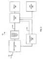
- FIG. 1illustrates a system 100 comprising an antenna apparatus with selectable elements, in one embodiment in accordance with the present invention.
- the system 100may comprise, for example without limitation, a transmitter and/or a receiver, such as an 802.11 access point, an 802.11 receiver, a set-top box, a laptop computer, a television, a PCMCIA card, a remote control, and a remote terminal such as a handheld gaming device.
- the system 100comprises an access point for communicating with one or more remote receiving nodes over a wireless link, for example, in an 802.11 wireless network.
- the system 100may receive data from a router connected to the Internet (not shown), and the system 100 may transmit the data to one or more remote receiving nodes (e.g., receiving nodes 130 A- 130 C).
- the system 100may also form a part of a wireless local area network (LAN) by enabling communications among two or more of the remote receiving nodes 130 A- 130 C.
- LANwireless local area network
- this disclosurewill focus on a specific embodiment for the system 100 , aspects of the invention are applicable to a wide variety of appliances, and are not intended to be limited to the disclosed embodiment.
- the system 100will be described as the access point for an 802.11 wireless network, the system 100 may also comprise the remote receiving node 130 A.
- the system 100includes a communication device 120 (e.g., a transceiver) and an antenna apparatus 110 .
- the communication device 120comprises virtually any device for converting data at a physical data rate and for generating and/or receiving a corresponding RF signal.
- the communication device 120may include, for example, a radio modulator/demodulator for converting data received by the system 100 (e.g., from a router) into the RF signal for transmission to one or more of the remote receiving nodes 130 A- 130 C.
- the communication device 120comprises circuitry for receiving data packets of video from the router and circuitry for converting the data packets into 802.11 compliant RF signals.
- the antenna apparatus 110includes a plurality of individually selectable antenna elements (not shown). When selected, each of the antenna elements produces a directional radiation pattern with gain (as compared to an omnidirectional antenna). As described further, the antenna apparatus 110 includes an antenna element selector device 310 to selectively couple one or more of the antenna elements to the communication device 120 .
- the antenna apparatus 110 and the antenna element selector device 310are further described in U.S. patent application Ser. No. 11/010,076 filed Dec. 9, 2004, now U.S. Pat. No. 7,292,198, U.S. patent application Ser. No. 11/022,080 filed Dec. 23, 2004, now U.S. registered patent number 7,193,562, and U.S. patent application Ser. No. 11/041,145 filed Jan. 21, 2005, now U.S. Pat. No. 7,362,280.
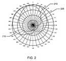
- FIG. 2illustrates various radiation patterns resulting from selecting different antenna elements of the antenna apparatus 110 of FIG. 1 , in one embodiment in accordance with the present invention.
- the antenna apparatus 110 used to produce the radiation pattern of FIG. 2comprises four selectable antenna elements ⁇ A
- the antenna elements(referred to as antenna elements A-D) are offset from each other by 90 degrees.
- Each antenna elementproduces a similar radiation pattern offset from the other radiation patterns (e.g., the radiation pattern of the antenna element A is offset by 90 degrees from the radiation pattern of the antenna element B). Accordingly, selecting one or more of the antenna elements A-D produces 15 different radiation patterns. Only three of the radiation patterns are shown in FIG. 2 , for clarity of explanation.
- a first radiation pattern 215is produced by selecting the antenna element A.
- the radiation patternis a generally cardioid pattern oriented with a center at about 315 degrees in azimuth.
- a second radiation pattern 205is produced by selecting the antenna element B.
- the antenna element Bis offset 90 degrees from antenna element A.
- the radiation pattern 205is therefore oriented with a center at about 45 degrees in azimuth.
- a combined radiation pattern 210depicted as a bold line, results from selecting the antenna element A and the antenna element B. It will be appreciated that by selecting one or more of the antenna elements A-D, fifteen radiation patterns can be produced by the antenna apparatus 110 .
- the antenna apparatus 110may produce a range of radiation patterns, ranging from highly directional to omnidirectional. Accordingly, the resulting radiation patterns are also referred as antenna configurations.
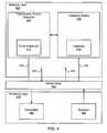
- FIG. 3illustrates an exemplary block diagram of the system 100 , in one embodiment in accordance with the present invention.
- the system 100includes a processor 320 coupled to a memory 330 .
- the processor 320may comprise a microcontroller, a microprocessor, or an application-specific integrated circuit (ASIC).
- the processor 320executes a program stored in the memory 330 .
- the memory 330also stores transmission control data, which may be retrieved by the processor 320 to control selection of the antenna configuration of the antenna apparatus 110 and selection of the physical data rate of the communication device 120 .
- the processor 320is coupled to the antenna element selector device 310 by a control bus 340 .
- the antenna element selector device 310is coupled to the antenna apparatus 110 to allow selection from among the multiple radiation patterns described in FIG. 2 .
- the processor 320controls the antenna element selector device 310 to select an antenna configuration (i.e., one of the multiple radiation patterns) of the antenna apparatus 110 .
- the processor 320is further coupled to the communication device 120 by the control bus 340 .
- the processor 320controls the communication device 120 to select a physical data rate (i.e., one of the multiple physical data rates).
- the processor 320controls the physical data rate at which the communication device 120 converts data bits into RF signals for transmission via the antenna apparatus 110 .
- the processor 320may receive packet data, Transmission Control Protocol (TCP) packet data, or User Datagram Protocol (UDP) packet data from an external local area network (LAN) 350 .
- the processor 320converts the TCP or UDP packet data into an 802.11 wireless protocol.
- the processor 320selects an antenna configuration of the antenna apparatus 110 and sends the 802.11 wireless protocol to the communication device 120 for conversion at the physical data rate into RF for transmission via the antenna apparatus 110 to the remote receiving node (e.g., the remote receiving node 130 A) over the wireless link (e.g., the wireless link 140 A).
- a method executed by the processor 320 for selecting the antenna configurationcomprises creating a table having transmission parameter control data for each remote receiving node 130 .
- the tableincludes link quality metrics for each antenna configuration. Some examples of link quality metrics are a success ratio, an effective user data rate, a received signal strength indicator (RSSI), and error vector magnitude (EVM).
- RSSIreceived signal strength indicator
- EVMerror vector magnitude
- the success ratiois defined as a number of data packets indicates as received by the particular remote receiving node 130 divided by a number of data packets transmitted to the remote receiving node 130 .
- the success ratiomay be dependent on the physical data rate used to transmit on the antenna configuration.
- the tablemay be sorted by the success ratio, for example, so that highly successful antenna configurations may be preferably selected.
- FIG. 4illustrates a block diagram of an exemplary software layer 405 , a device driver 450 , and a hardware layer 455 , in one embodiment in accordance with the present invention.
- the software layer 405 and the device driver 450comprise instructions executed by the processor 320 (in FIG. 3 ).
- the hardware layer 455comprises hardware elements of the system 100 described with respect to FIG. 3 , such as the antenna selector device 310 and the communication device 120 .
- aspects of the inventionmay be implemented with any combination of software, hardware, and firmware elements.
- the software layer 405includes a transmission control selection 410 and a feedback module 420 .
- the transmission control selection 410includes a probe scheduler 415 .
- the feedback module 420includes a database 425 .
- the hardware layer 455includes a transmitter 460 and a receiver 465 .
- the transmission control selection 410is linked to the feedback module 420 .
- the transmission control selection 410communicates with the device driver 450 via link 430 .
- the feedback modulecommunicates with the device driver 450 via link 435 .
- the device driver 450receives packets via link 440 from the software layer 405 and sends the packets to the transmitter 460 in the hardware layer 455 .
- the device driver 450also receives packets from the receiver 465 in the hardware layer 455 and sends the packets to the software layer 405 via link 445 .
- the transmission control selection 410comprises software elements configured to select for the device driver 450 the current antenna configuration and the current physical data rate based on the feedback module 420 or based on the probe scheduler 415 .
- the probe scheduler 415comprises software elements configured to determine for the transmission control selection 410 an unused antenna configuration and an unused physical data rate based on predetermined criteria.
- One example of the predetermined criteriais determining an unused antenna configuration after the device driver 450 indicates as received 5 consecutive packets.
- the feedback module 420comprises software elements configured to update link quality metrics for each antenna configuration and each physical data rate based on feedback from the device driver 450 .
- the feedback module 420is configured to maintain the link quality metrics in the database 425 .
- the operation of the software layer 405 , the device driver 450 , and the hardware layer 455are described below with respect to FIG. 6 and FIG. 7 .
- the transmission control selection 410may select, for example, an antenna configuration for the antenna apparatus 110 that minimizes interference for communicating over the wireless link 140 A to the remote receiving node 130 A based on feedback (i.e., direct or indirect) from the receiving node.
- the device driver 450indicates whether the remote receiving node received transmitted packets on a particular antenna configuration and physical data rate.
- the transmission selection control 410may select another antenna configuration for communicating over the wireless link 140 B to the remote receiving node 130 B based on the feedback, thereby changing the radiation pattern of the antenna apparatus 110 to minimize interference in the wireless link 140 A and/or the wireless link 140 B.
- the transmission control selection 410may select the appropriate antenna configuration corresponding to a maximum gain for the wireless links 140 A- 140 C. Alternatively, the transmission control selection 410 may select the antenna configuration corresponding to less than maximal gain, but corresponding to reduced interference, in the wireless links 140 A- 140 C. A further advantage is that transmission control selection 410 may select the physical data rate that provides the maximum effective user data rate at the remote receiving node 130 A over the wireless link 140 A.
- FIG. 5illustrates an exemplary table 500 of transmission control data showing a success ratio 540 and a received signal strength indicator (RSSI) 550 for multiple antenna configurations 510 , in one embodiment in accordance with the present invention.
- the rows of the table 500correspond to the multiple antenna configurations 510 of the antenna apparatus 110 .
- a table of transmission control data for the antenna apparatus 110 having four selectable antenna elements ⁇ A, B, C, D ⁇would have fifteen possible antenna configurations 510 comprising the set ⁇ A
- the table 500is kept in the database 425 ( FIG. 4 ) for each of the remote receiving nodes 130 A-C.
- Each of the remote receiving nodes 130 A-Cmay require different antenna configurations and/or physical data rates for optimal performance of each of the wireless links 140 A-C, therefore multiple table 500 s may be kept.
- the processor 320would maintain a separate table 500 for each of the five remote receiving nodes 130 A-C. For ease of discussion, only a single table 500 will be discussed.
- the table 500stores, for each antenna configuration 510 , a number of attempted transmissions 520 and a number of successful transmissions 530 .
- the feedback module 420updates the number of attempted transmissions 520 for the current antenna configuration after the device driver 450 (in FIG. 4 ) indicates a packet as transmitted the remote receiving node.
- the feedback module 420updates the number of successful transmissions 530 after the device driver 450 indicates the packet as received by the remote receiving node.
- the feedback module 420may update the number of attempted transmissions 520 after the device driver 450 indicates whether the remote receiving node received the packet.
- the table 500also stores a success ratio 540 and a RSSI 550 .
- the success ratio 540 and the RSSI 550are illustrated in the table 500 , other link quality metrics may be stored in the table 500 , such as voltage standing wave ratio (VSWR), signal quality, bit error rate, and error vector magnitude (EVM).
- VSWRvoltage standing wave ratio
- EVMerror vector magnitude
- the success ratio 540comprises a computation of the number of successful transmissions 530 divided by the number of attempted transmissions 520 .
- the success ratio 540typically is updated by the feedback module 420 for each change in the number of attempted transmissions 520 :
- the RSSI 550comprises an indication of the strength of the incoming (received) signal in the receiver 465 (e.g., as measured on an 802.11 ACK packet received from the remote receiving node 130 A in response to a packet transmitted to the remote receiving node 130 A).
- the RSSI 550may provide a better measurement than the success ratio 540 for differentiating between antenna configurations.
- the RSSI 550may provide a better link quality metric for determining the current antenna configuration when each antenna configuration 510 has small values for the number of attempted transmissions 520 and the number of successful transmissions 530 .
- each of the two separate antenna configurationshas a success ratio 540 of 100% (e.g., 2 attempted transmissions over 2 successful transmissions).
- the RSSI 550may provide a more precise link quality metric. If one antenna configuration has the RSSI 550 value of 110 and the other antenna configuration has the RSSI 550 value of 115, for example, then the antenna configuration with the stronger RSSI 550 would potentially provide a more stable wireless link (e.g., over wireless link 140 A).
- FIG. 6illustrates a flowchart of an exemplary method for transmission control selection with respect to FIGS. 3 , 4 , and 5 , in one embodiment in accordance with the present invention.
- the feedback module 420initializes the database 425 .
- the feedback module 420may initialize the number of attempted transmissions 520 and the number of successful transmissions 530 to zero.
- the feedback module 420may determine alternative initialization values for the table 500 .
- the feedback module 420may determine initialization values for an antenna configuration that provides a substantially omnidirectional radiation pattern.
- the initialization values for the antenna configurationmay be a high value for the success ratio 540 or the RSSI 550 to force the transmission control selection 410 to select the antenna configuration for the device driver 450 .
- the device driver 450receives a packet for transmission from the software layer 405 .
- device driver 450determines the type of transmission. In general, the device driver 450 distinguishes between initial transmission of a packet and retransmission of the packet. Based on a determination to initially transmit the packet, the device driver 450 queries the transmission control selection 410 for the current antenna configuration and the current physical data rate.
- the transmission control selection 410determines whether to perform a probe by referencing the probe scheduler 415 . If the probe scheduler 415 determines not to perform a probe, in step 625 , the transmission control selection 410 selects the current antenna configuration for the antenna apparatus 110 from the multiple antenna configurations in the table 500 . For example, the transmission control selection 410 selects the best ranked antenna configuration having the highest success ratio 540 . In an alternative embodiment, the transmission control selection 410 selects the antenna configuration having the highest RSSI 550 .
- the transmission control selection 410selects the current physical data rate from the multiple physical data rates provided by the communication device 120 , as described further with respect to FIG. 8 .
- the multiple physical data ratesmay be defined as in the IEEE 802.11 specification for wireless networks, including, for example, the physical data rates of 1 Mbps, 2 Mbps, 5.5 Mbps, and 11 Mbps for IEEE 802.11b.
- the device driver 450sends the packet to the transmitter 460 of the hardware layer 455 .
- the transmitter 460transmits the packet on the current antenna configuration at the current physical data rate over the wireless link 140 to a particular remote receiving node (e.g., the remote receiving node 130 A).
- retransmission of the packetis a high priority if the packet is not indicated as received by the remote receiving node 130 A.
- the need for retransmissionmay indicate problems in the wireless link 140 A.
- the transmission control selection 410attempts to determine the antenna configuration for retransmission and the physical data rate for retransmission that is most likely to be successful.
- the transmission control selection 410selects an antenna configuration for retransmission.
- the transmission control selection 410selects the next lower ranked antenna configuration in the table 500 .
- the transmission control selection 410selects a physical data rate for retransmission.
- the transmitter 460then transmits the packet in step 635 as described herein.
- step 650the transmission control selection 410 selects the same current antenna configuration, but, in step 655 , the transmission control selection 410 incrementally lowers the physical data rate at which the packet is retransmitted to the remote receiving node 130 A.
- the lower physical data rateshould give the remote receiving node 130 A more time to obtain a successful reception of the packet.
- the transmission control selection 410alternates between selecting the next antenna configuration based on the success ratio 540 and the RSSI 550 . For example, on the first retransmission, the transmission control selection 410 selects the next lower ranked antenna configuration based on the success ratio 540 . If the device driver 450 determines that the remote receiving node 130 A did not indicate reception of the packet, the device driver 450 will retransmit the packet, and the transmission control selection 410 will select the next lower ranked antenna configuration based on the RSSI 550 . For each subsequent retransmission to the remote receiving node 130 A, the transmission control selection 410 alternates between selecting antenna configurations based on the success ratio 540 and the RSSI 550 .
- the transmission control selection 410may determine to perform a probe of unused antenna configurations.
- Probingis the temporary changing of the current antenna configuration to one of the unused antenna configurations for transmission of a packet.
- the unused antenna configurationis any antenna configuration that is not the current antenna configuration.
- Probingallows the feedback module 420 to update the values of the table 500 for the unused antenna configurations. Probing consciously and temporarily changes the current antenna configuration to ensure that the database 425 is not stale. Additionally, probing allows the system 100 to anticipate changes in the wireless link 140 A.
- the transmission control selection 410in step 640 selects an unused antenna configuration. Transmitting on the unused antenna configuration may result in a higher ranked success ratio 540 than the current antenna configuration. Additionally, in step 645 , the transmission control selection 410 also may probe an unused physical data rate as discussed further below. In step 635 , the transmitter 460 transmits the probe packet to the remote receiving node 130 A.
- FIG. 7illustrates a flowchart of an exemplary method for feedback processing with respect to FIGS. 3 , 4 , and 5 , in one embodiment in accordance with the present invention.
- the methodbegins in step 705 after transmission of the packet, as described with respect to FIG. 6 .
- the feedback module 420increments the number of attempted transmissions 520 for the current antenna configuration.
- step 715the device driver 450 determines whether the remote receiving node 130 A indicated reception of the transmitted packet as discussed in regard to FIG. 6 . If the remote receiving node 130 A indicated reception of the packet, in step 720 , the feedback module 420 increments the number of successful transmissions 530 for the current antenna configuration. In step 725 , in some embodiments, whether the remote receiving node 130 A indicated reception of the packet or not, the feedback module 420 computes the success ratio 540 for each antenna configuration 510 .
- the feedback module 420determines a variety of link quality metrics which allow the transmission control selection 410 to select an antenna configuration. For example, in step 730 , the feedback module 420 may determine the RSSI 550 for each antenna configuration 510 for the remote receiving node 130 A. In step 735 , the feedback module 420 may determine the effective user data rate for each physical data rate of each antenna configuration 510 .
- the feedback module 420ranks each of the antenna configurations 510 by the success ratio 540 .
- the feedback module 420may also rank the antenna configurations 510 by the RSSI 550 .
- the feedback module 420may rank each physical data rate of each antenna configuration 510 for the remote receiving node 130 A by the effective user data rate. This enables the transmission control selection 410 to select a physical data rate that may have a higher effective user data rate than the current physical data rate.
- the software layer 405determines link quality metrics, such as the success ratio 540 and the RSSI 550 , such that for each packet, an antenna configuration is selected having a high success ratio 540 to transmit to the remote receiving nodes 130 A- 130 C via the wireless links 140 A- 140 C.
- link quality metricssuch as the success ratio 540 and the RSSI 550 , such that for each packet, an antenna configuration is selected having a high success ratio 540 to transmit to the remote receiving nodes 130 A- 130 C via the wireless links 140 A- 140 C.
- Thisprovides greater throughput because the software layer 405 may select from those antenna configurations having high success ratios.
- the software layer 405minimized packet loss because the feedback module 420 constantly processes link quality metrics to determine the stability of the wireless links 140 A-C to the remote receiving nodes 130 A-C.
- the transmission control selection 410may execute an alternative method to select the new antenna configuration to facilitate retransmission of the packet over the wireless link 140 A to the remote receiving node 130 A. For example, the transmission control selection 410 may select the new antenna configuration as the next lower ranked antenna configuration in the table 500 . The transmission control selection 410 may, for each subsequent retransmission of the packet, select the new antenna configuration as a next lower ranked antenna configuration.
- the transmission control selection 410may select a new antenna configuration by “walking down” the ranked table 500 until an antenna configuration successfully transmits the packet.
- walking down the table 500may not rapidly find a new good antenna configuration.
- the transmission control selection 410may select up to three next lower ranked antenna configurations on which to retransmit. If none of these relatively highly ranked antenna configurations is successful, then the wireless link 140 A may have changed, and the transmission control selection 410 may randomly select the new antenna configuration from among any of the remaining available antenna configurations. In this manner, the transmission control selection 410 does not waste time searching sequentially through the table 500 for a good antenna configuration.
- the feedback module 420may further optimize selecting the new antenna configuration.
- the table 500 in the database 425may be “aged.” For example, if successful transmission for a number of packets is disrupted on the current antenna configuration because of interference, the transmission control selection 410 may not rapidly change the current antenna configuration in response to the interference. An increase in the number of unsuccessful transmissions will only slightly decrease the success ratio 540 for the current antenna configuration.
- the wireless link 140 Awill have an 80% success ratio 540 . If the wireless link 140 A encounters 5 consecutive unsuccessful packet transmissions, the success ratio 540 drops to approximately 76%. However, by having the feedback module 420 age the table 500 by a predetermined value, such as 2, the transmission control selection 410 will be more sensitive to change in the wireless link 140 A, thereby improving the speed of selecting the new antenna configuration.
- the current antenna configurationwould have 40 successful transmissions out of 50 attempted transmissions, again having a success ratio 540 of 80%. If the wireless link 140 A again encounters 5 consecutive unsuccessful packet transmissions, the success ratio drops to approximately 72%. In this manner, by aging of the table 500 by the feedback module 420 , a smaller number of unsuccessful transmissions may have a greater impact on the success ratio of the current antenna configuration, thereby allowing the transmission control selection 410 to more rapidly determine a better new antenna configuration.
- the transmission control selection 410may select the new antenna configuration from antenna configurations “historically” known to have a higher success ratio 540 . For example, over a period of time the feedback module 420 may rank one or more antenna configurations as having a consistently higher success ratio 540 . The transmission control selection 410 may select the new antenna configuration from among the historically good antenna configurations.
- the feedback module 420may incorporate a threshold value in the ranking of the antenna configurations 510 .
- the threshold valuesets a limit above which the success ratio 540 of an antenna configuration must reach before the antenna configuration is ranked higher and/or lower than the current antenna configuration. For example, a threshold value set to 3% prevents the transmission control selection 410 from selecting a new antenna configuration having a success ratio 540 only 1% higher than the success ratio 540 of the current antenna configuration.
- the incorporation of the threshold valueprovides stability to the wireless links 140 A-C because the transmission control selection 405 will not change to the new antenna configuration unless the new antenna configuration has a sufficiently higher success ratio 540 than the current antenna configuration.
- Providing the threshold valuelimits the overhead associated with selecting from all of the antenna configurations 510 , while still allowing new antenna configurations with sufficiently higher success ratios 540 to be selected.
- FIG. 8illustrates an exemplary table 800 of effective user data rates 820 for multiple physical data rates 810 , in one embodiment in accordance with the present invention.
- the feedback module 420i.e., executed by the processor 320 ) maintains the table 800 in the database 425 for each allowable antenna configuration 510 of the antenna apparatus 110 and for each remote receiving node 130 A-C.
- the methodwill describe the table 800 for only the current antenna configuration.
- the table 800includes a computation of the effective user data rate 820 for each allowable physical data rate 810 .
- the effective user data rate 820 for a particular physical data rateis computed as the product of the success ratio 540 ( FIG. 5 ) associated with the current antenna configuration and the transactional throughput of the physical data rate.
- the effective user data rate 820 for the physical data rate of 54 Mbps for an antenna configuration having the success ratio 540 of 80%is computed as follows:
- the feedback module 420computes and tracks the effective user data rate 820 for each allowable physical data rate 810 because a higher physical data rate does not necessarily lead to a higher data throughput over the wireless links 140 A-C. For example, switching to a lower physical data rate for an antenna configuration with a relatively high success ratio 540 may provide higher overall data throughput than switching to a higher physical data rate for an antenna configuration having a relatively lower success ratio 540 . In this way, the transmission control selection 410 may change the current physical data rate to the new physical data rate which provides the higher effective user data rate 820 over the wireless links 140 A-C.
- the probe scheduler 415may determine to probe one or more unused physical data rates to select the new physical data rate.
- the feedback module 420may update the table 800 for the unused physical data rates.
- the feedback module 420determines the effective user data rate 820 for the unused physical data rate and ranks the table 800 by the effective user data rate 820 .
- the transmission control selection 410may select the new physical data rate having the higher effective user data rate 820 . Therefore, the feedback module 420 prevents the table 800 data from becoming stale and facilitates selection of the appropriate new physical data rate.
- the feedback module 420ages the table 800 in the database 425 in a manner similar to the description herein with respect to the aging of table 500 .
- the transmission control selection 410may more rapidly determine the new physical data rate.
- the transmission control selection 410may select the new physical data rate from the physical data rates 810 “historically” known to have a higher effective user data rate 820 .
- the feedback module 420may track the physical data rate having the consistently higher effective user data rate 820 .
- the transmission control selection 410selects the new physical data rate from among the historically higher physical data rates.
- the feedback module 420may execute a method for incorporating a threshold value for selecting the new physical data rate.
- the threshold valuesets a limit above which the effective user data rate 820 of a physical data rate must reach before that physical data rate is selected as the new physical data rate.
- the incorporation of the threshold valueallows the software layer 405 to maximize data throughput, while still allowing physical data rates with sufficiently higher effective user data rates 820 to be selected as the new physical data rate.
- the feedback module 420may track the success ratio 540 for a limited number of antenna configurations and the effective user data rate 820 for a limited number of physical data rates 810 .
- the feedback module 420requires less memory and processing time to maintain and determine the respective success ratio 540 and the effective user data rate 820 .
- the feedback module 420maps the allowable antenna configurations into logical antennas and defines a relationship between each logical antenna and at least one other logical antenna.
- the feedback module 420also maps the allowable physical data rates 810 into logical data rates and defines a relationship between each logical data rate and at least one other logical data rate.
- one exemplary mappingdefines the current logical antenna as having an upper logical antenna and a lower logical antenna.
- the upper logical antennamay be the antenna configuration having radiation pattern 205 .
- the lower logical antennamay be the antenna configuration having the combined radiation pattern 210 .
- the current logical antenna, the upper logical antenna, and the lower logical antennamay be any of the antenna configurations, and need not be “neighboring” antenna configurations as depicted in FIG. 2 .
- the exemplary mapping for the current logical data ratedefines the current logical antenna as having an upper logical data rate and a lower logical data rate.
- the current logical data rate corresponding to the physical data rate of 36 Mbpshas an upper logical data rate corresponding to the physical data rate of 48 Mbps and a lower logical data rate corresponding to the physical data rate of 24 Mbps.
- the feedback module 420tracks three values for the success ratio 540 and three values for the effective user data rate 820 .
- the feedback module 420is able to rapidly rank from the mappings a new logical antenna or logical data rate which may be used for transmission via the wireless links 140 A-C. It will be understood by the skilled artisan that various alternative mappings may be implemented and tracked by the feedback module 420 without departing from the spirit of the invention as described herein (for example, an upper upper logical antenna and a lower lower logical antenna).
- the transmission control selection 410may select, for transmission of a packet by the device driver 450 , the upper logical antenna or the lower logical antenna that has a higher success ratio 540 than the current logical antenna. To determine whether the upper logical antenna or the lower logical antenna has a higher success ratio 540 , the transmission control selection 410 periodically probes, or transmits packets on, the upper logical antenna and the lower logical antenna allowing the feedback module 420 to update the database 425 . Then, if transmission control selection 410 determines to change the current logical antenna, the feedback module 420 determines whether the upper logical antenna or the lower logical antenna provides the higher success ratio 540 and the transmission control selection 410 selects that logical antenna as the new logical antenna.
- the feedback module 420executes a method for optimizing the physical data rate.
- the transmission control selection 410may change the current logical data rate to the new logical data rate that provides the higher effective user data rate 820 over the wireless links 140 A-C.
- the transmission control selection 410may probe the upper logical data rate and the lower logical data rate to allow the feedback module 420 to update the database 425 and determine which logical data rate provides the higher effective user data rate 820 .
- the transmission control selection 410may further execute other optimizations for the selection of the new logical antenna or the new logical data rate.
- the transmission control selection 410alternately transmits a packet on the upper logical antenna and the lower logical antenna for each transmission on the current logical antenna. This provides the advantage of quickly converging to the new logical antenna having the higher success ratio 540 , because a probe is sent alternatively on the upper logical antenna and the lower logical antenna in an effort to determine if either the upper logical antenna or the lower logical antenna has a higher success ratio 540 than the current logical antenna.
- the transmission control selection 410may rapidly converge on the new logical data rate having the higher effective user data rate 820 by transmitting a packet at the upper logical data rate and the lower logical data rate.
- the transmission control selection 410may periodically probe on the upper and lower logical antennas and/or the upper and lower logical data rates. For example, the transmission control selection 410 may probe once on the upper and lower logical antennas for every 5 packets sent on the current logical antenna.
Landscapes
- Engineering & Computer Science (AREA)
- Computer Networks & Wireless Communication (AREA)
- Signal Processing (AREA)
- Mobile Radio Communication Systems (AREA)
Abstract
Description
success ratio 540=80%- physical data rate=54 Mbps
- protocol overhead=26.7 Mbps
- effective
user data rate 820=80%*(54 Mpbs−26.7 Mbps)=21.84 Mbps.
Claims (7)
Priority Applications (1)
| Application Number | Priority Date | Filing Date | Title |
|---|---|---|---|
| US12/283,223US7877113B2 (en) | 2004-08-18 | 2008-09-09 | Transmission parameter control for an antenna apparatus with selectable elements |
Applications Claiming Priority (5)
| Application Number | Priority Date | Filing Date | Title |
|---|---|---|---|
| US60315704P | 2004-08-18 | 2004-08-18 | |
| US60271104P | 2004-08-18 | 2004-08-18 | |
| US62533104P | 2004-11-05 | 2004-11-05 | |
| US11/180,329US7899497B2 (en) | 2004-08-18 | 2005-07-12 | System and method for transmission parameter control for an antenna apparatus with selectable elements |
| US12/283,223US7877113B2 (en) | 2004-08-18 | 2008-09-09 | Transmission parameter control for an antenna apparatus with selectable elements |
Related Parent Applications (1)
| Application Number | Title | Priority Date | Filing Date |
|---|---|---|---|
| US11/180,329DivisionUS7899497B2 (en) | 2004-08-18 | 2005-07-12 | System and method for transmission parameter control for an antenna apparatus with selectable elements |
Publications (2)
| Publication Number | Publication Date |
|---|---|
| US20090022066A1 US20090022066A1 (en) | 2009-01-22 |
| US7877113B2true US7877113B2 (en) | 2011-01-25 |
Family
ID=35910285
Family Applications (3)
| Application Number | Title | Priority Date | Filing Date |
|---|---|---|---|
| US11/180,329Active2028-12-02US7899497B2 (en) | 2004-08-18 | 2005-07-12 | System and method for transmission parameter control for an antenna apparatus with selectable elements |
| US12/283,223Expired - LifetimeUS7877113B2 (en) | 2004-08-18 | 2008-09-09 | Transmission parameter control for an antenna apparatus with selectable elements |
| US13/037,250Expired - Fee RelatedUS8150470B2 (en) | 2004-08-18 | 2011-02-28 | System and method for transmission parameter control for an antenna apparatus with selectable elements |
Family Applications Before (1)
| Application Number | Title | Priority Date | Filing Date |
|---|---|---|---|
| US11/180,329Active2028-12-02US7899497B2 (en) | 2004-08-18 | 2005-07-12 | System and method for transmission parameter control for an antenna apparatus with selectable elements |
Family Applications After (1)
| Application Number | Title | Priority Date | Filing Date |
|---|---|---|---|
| US13/037,250Expired - Fee RelatedUS8150470B2 (en) | 2004-08-18 | 2011-02-28 | System and method for transmission parameter control for an antenna apparatus with selectable elements |
Country Status (5)
| Country | Link |
|---|---|
| US (3) | US7899497B2 (en) |
| EP (1) | EP1782639B1 (en) |
| CN (1) | CN1906955B (en) |
| TW (1) | TWI351790B (en) |
| WO (1) | WO2006023239A2 (en) |
Cited By (12)
| Publication number | Priority date | Publication date | Assignee | Title |
|---|---|---|---|---|
| US20070026807A1 (en)* | 2005-07-26 | 2007-02-01 | Ruckus Wireless, Inc. | Coverage enhancement using dynamic antennas |
| US20080070509A1 (en)* | 2006-08-18 | 2008-03-20 | Kish William S | Closed-Loop Automatic Channel Selection |
| US20090310590A1 (en)* | 2004-08-18 | 2009-12-17 | William Kish | Transmission and Reception Parameter Control |
| US8422540B1 (en) | 2012-06-21 | 2013-04-16 | CBF Networks, Inc. | Intelligent backhaul radio with zero division duplexing |
| US8467363B2 (en) | 2011-08-17 | 2013-06-18 | CBF Networks, Inc. | Intelligent backhaul radio and antenna system |
| US20160057003A1 (en)* | 2013-03-22 | 2016-02-25 | Cambridge Communication Systems Limited | Node partitioning |
| US20190158198A1 (en)* | 2017-11-21 | 2019-05-23 | General Test Systems Inc. | Method and device for measuring radiation pattern of antenna array, and computer readable storage medium |
| US10491278B2 (en) | 2017-12-15 | 2019-11-26 | Industrial Technology Research Institute | Wireless communication device with hybrid beamforming and control method thereof |
| US10541743B2 (en) | 2017-12-14 | 2020-01-21 | Industrial Technology Research Institute | Communication system and operating method thereof |
| US10615858B2 (en) | 2018-05-30 | 2020-04-07 | Industrial Technology Research Institute | Communication system and operating method thereof |
| US11418457B1 (en)* | 2016-01-12 | 2022-08-16 | Sprint Spectrum L.P. | Method and apparatus for selecting a voice coding rate based on the air interface efficiency of the serving base station |
| US11722412B1 (en) | 2020-09-28 | 2023-08-08 | Amazon Technologies, Inc. | Dynamically managing connection parameters among multiple computing devices |
Families Citing this family (86)
| Publication number | Priority date | Publication date | Assignee | Title |
|---|---|---|---|---|
| US7295509B2 (en) | 2000-09-13 | 2007-11-13 | Qualcomm, Incorporated | Signaling method in an OFDM multiple access system |
| US9130810B2 (en) | 2000-09-13 | 2015-09-08 | Qualcomm Incorporated | OFDM communications methods and apparatus |
| US9148256B2 (en) | 2004-07-21 | 2015-09-29 | Qualcomm Incorporated | Performance based rank prediction for MIMO design |
| US9137822B2 (en) | 2004-07-21 | 2015-09-15 | Qualcomm Incorporated | Efficient signaling over access channel |
| US7880683B2 (en)* | 2004-08-18 | 2011-02-01 | Ruckus Wireless, Inc. | Antennas with polarization diversity |
| US8031129B2 (en) | 2004-08-18 | 2011-10-04 | Ruckus Wireless, Inc. | Dual band dual polarization antenna array |
| US20060111054A1 (en)* | 2004-11-22 | 2006-05-25 | Interdigital Technology Corporation | Method and system for selecting transmit antennas to reduce antenna correlation |
| US7646343B2 (en)* | 2005-06-24 | 2010-01-12 | Ruckus Wireless, Inc. | Multiple-input multiple-output wireless antennas |
| US9246560B2 (en) | 2005-03-10 | 2016-01-26 | Qualcomm Incorporated | Systems and methods for beamforming and rate control in a multi-input multi-output communication systems |
| US9154211B2 (en) | 2005-03-11 | 2015-10-06 | Qualcomm Incorporated | Systems and methods for beamforming feedback in multi antenna communication systems |
| US9143305B2 (en)* | 2005-03-17 | 2015-09-22 | Qualcomm Incorporated | Pilot signal transmission for an orthogonal frequency division wireless communication system |
| US9520972B2 (en) | 2005-03-17 | 2016-12-13 | Qualcomm Incorporated | Pilot signal transmission for an orthogonal frequency division wireless communication system |
| US9461859B2 (en)* | 2005-03-17 | 2016-10-04 | Qualcomm Incorporated | Pilot signal transmission for an orthogonal frequency division wireless communication system |
| US9184870B2 (en) | 2005-04-01 | 2015-11-10 | Qualcomm Incorporated | Systems and methods for control channel signaling |
| US9408220B2 (en) | 2005-04-19 | 2016-08-02 | Qualcomm Incorporated | Channel quality reporting for adaptive sectorization |
| US9036538B2 (en) | 2005-04-19 | 2015-05-19 | Qualcomm Incorporated | Frequency hopping design for single carrier FDMA systems |
| US8611284B2 (en) | 2005-05-31 | 2013-12-17 | Qualcomm Incorporated | Use of supplemental assignments to decrement resources |
| US8879511B2 (en) | 2005-10-27 | 2014-11-04 | Qualcomm Incorporated | Assignment acknowledgement for a wireless communication system |
| US8565194B2 (en) | 2005-10-27 | 2013-10-22 | Qualcomm Incorporated | Puncturing signaling channel for a wireless communication system |
| US9179319B2 (en) | 2005-06-16 | 2015-11-03 | Qualcomm Incorporated | Adaptive sectorization in cellular systems |
| US8599945B2 (en)* | 2005-06-16 | 2013-12-03 | Qualcomm Incorporated | Robust rank prediction for a MIMO system |
| US8885628B2 (en) | 2005-08-08 | 2014-11-11 | Qualcomm Incorporated | Code division multiplexing in a single-carrier frequency division multiple access system |
| US7583649B1 (en)* | 2005-08-12 | 2009-09-01 | Marvell International Ltd. | Rate adaptation |
| US9209956B2 (en) | 2005-08-22 | 2015-12-08 | Qualcomm Incorporated | Segment sensitive scheduling |
| US20070041457A1 (en) | 2005-08-22 | 2007-02-22 | Tamer Kadous | Method and apparatus for providing antenna diversity in a wireless communication system |
| US8644292B2 (en) | 2005-08-24 | 2014-02-04 | Qualcomm Incorporated | Varied transmission time intervals for wireless communication system |
| US9136974B2 (en) | 2005-08-30 | 2015-09-15 | Qualcomm Incorporated | Precoding and SDMA support |
| US8666445B2 (en)* | 2005-10-25 | 2014-03-04 | Kyocera Corporation | Apparatus, system, and method for transmission antenna switching in a portable communication device |
| US9225488B2 (en) | 2005-10-27 | 2015-12-29 | Qualcomm Incorporated | Shared signaling channel |
| US9210651B2 (en) | 2005-10-27 | 2015-12-08 | Qualcomm Incorporated | Method and apparatus for bootstraping information in a communication system |
| US9144060B2 (en) | 2005-10-27 | 2015-09-22 | Qualcomm Incorporated | Resource allocation for shared signaling channels |
| US8045512B2 (en) | 2005-10-27 | 2011-10-25 | Qualcomm Incorporated | Scalable frequency band operation in wireless communication systems |
| US9225416B2 (en) | 2005-10-27 | 2015-12-29 | Qualcomm Incorporated | Varied signaling channels for a reverse link in a wireless communication system |
| US9088384B2 (en) | 2005-10-27 | 2015-07-21 | Qualcomm Incorporated | Pilot symbol transmission in wireless communication systems |
| US8693405B2 (en) | 2005-10-27 | 2014-04-08 | Qualcomm Incorporated | SDMA resource management |
| US9172453B2 (en) | 2005-10-27 | 2015-10-27 | Qualcomm Incorporated | Method and apparatus for pre-coding frequency division duplexing system |
| US8582548B2 (en)* | 2005-11-18 | 2013-11-12 | Qualcomm Incorporated | Frequency division multiple access schemes for wireless communication |
| US8831607B2 (en) | 2006-01-05 | 2014-09-09 | Qualcomm Incorporated | Reverse link other sector communication |
| EP2464028A1 (en)* | 2006-02-28 | 2012-06-13 | Rotani Inc. | Methods and apparatus for overlapping mimo antenna physical sectors |
| EP2016693B1 (en)* | 2006-05-09 | 2018-07-18 | Telefonaktiebolaget LM Ericsson (publ) | Method and apparatus for improved single cell adaption due to change in environment |
| EP2022210A1 (en)* | 2006-05-15 | 2009-02-11 | Telefonaktiebolaget L.M. Ericsson | Wireless multicast for layered media |
| US7944890B2 (en)* | 2006-05-23 | 2011-05-17 | Interdigital Technology Corporation | Using windows specified object identifiers (OIDs) for an antenna steering algorithm |
| US20080064353A1 (en)* | 2006-09-07 | 2008-03-13 | Motorola, Inc. | Method and apparatus for base station directed selection of a multiple antenna configuration |
| KR101141916B1 (en)* | 2007-01-23 | 2012-05-03 | 닛본 덴끼 가부시끼가이샤 | Wireless control method |
| KR101531053B1 (en)* | 2007-08-10 | 2015-06-25 | 한국전자통신연구원 | System and Method for modulating data Adaptively using selection of Multi Antenna |
| US20100238835A1 (en)* | 2007-12-05 | 2010-09-23 | Thomson Licensing | Method for characterizing a communication link in a communication network |
| US20090279478A1 (en)* | 2008-05-06 | 2009-11-12 | Motorola, Inc. | Method and apparatus for facilitating dynamic cooperative interference reduction |
| GB0813027D0 (en)* | 2008-07-16 | 2008-08-20 | Advanced Risc Mach Ltd | Error detection |
| US8217843B2 (en)* | 2009-03-13 | 2012-07-10 | Ruckus Wireless, Inc. | Adjustment of radiation patterns utilizing a position sensor |
| US8698675B2 (en)* | 2009-05-12 | 2014-04-15 | Ruckus Wireless, Inc. | Mountable antenna elements for dual band antenna |
| WO2010138735A1 (en)* | 2009-05-27 | 2010-12-02 | At&T Intellectual Property I, L.P. | Transmit antenna subset selection for retransmission |
| IT1394413B1 (en) | 2009-06-17 | 2012-06-15 | Pirelli & C Spa | SYSTEM OF SWITCHED ANTENNAS FOR A WIRELESS LOCAL NETWORK |
| KR101751995B1 (en)* | 2009-06-19 | 2017-06-28 | 엘지전자 주식회사 | Method of minimizing feedback overhead using spatial channel covariance in a multi input and multi output (mimo) system |
| TWI433572B (en)* | 2009-11-04 | 2014-04-01 | Mediatek Singapore Pte Ltd | Transmission power management method and communication system |
| US8634482B2 (en)* | 2009-11-17 | 2014-01-21 | Cooper Technologies Company | High power radio device communication parameter configuration and methods using limited configuration power |
| US8185120B2 (en) | 2010-03-26 | 2012-05-22 | Microsoft Corporation | Cellular service with improved service availability |
| US9407012B2 (en) | 2010-09-21 | 2016-08-02 | Ruckus Wireless, Inc. | Antenna with dual polarization and mountable antenna elements |
| EP2641418B1 (en)* | 2010-11-16 | 2018-07-11 | Telefonaktiebolaget LM Ericsson (publ) | Method and arrangement for cell outage compensation in a communication network system |
| US9084134B2 (en) | 2010-11-16 | 2015-07-14 | Telefonaktiebolaget L M Ericsson (Publ) | Method and arrangement for probing of alternative antenna configurations in a communication network system |
| EP2506625B1 (en)* | 2011-03-29 | 2017-11-01 | Alcatel Lucent | A small cell base station comprising multiple antennas, and a method of controlling reception pattern by selecting a subset of the antennas for use |
| CN104283590B (en)* | 2012-01-09 | 2017-11-17 | 光宝电子(广州)有限公司 | Antenna array control method and the communicator using this method |
| EP2645592A1 (en)* | 2012-03-29 | 2013-10-02 | Alcatel Lucent | Method for performing retransmissions in a radio communication system, first transceiver apparatus, and second transceiver apparatus thereof |
| US9570799B2 (en) | 2012-09-07 | 2017-02-14 | Ruckus Wireless, Inc. | Multiband monopole antenna apparatus with ground plane aperture |
| US9681311B2 (en) | 2013-03-15 | 2017-06-13 | Elwha Llc | Portable wireless node local cooperation |
| WO2014146038A1 (en) | 2013-03-15 | 2014-09-18 | Ruckus Wireless, Inc. | Low-band reflector for dual band directional antenna |
| US9491637B2 (en) | 2013-03-15 | 2016-11-08 | Elwha Llc | Portable wireless node auxiliary relay |
| US20140349696A1 (en)* | 2013-03-15 | 2014-11-27 | Elwha LLC, a limited liability corporation of the State of Delaware | Supporting antenna assembly configuration network infrastructure |
| US9793596B2 (en) | 2013-03-15 | 2017-10-17 | Elwha Llc | Facilitating wireless communication in conjunction with orientation position |
| US9608862B2 (en) | 2013-03-15 | 2017-03-28 | Elwha Llc | Frequency accommodation |
| US9241281B2 (en)* | 2013-06-12 | 2016-01-19 | Honeywell International Inc. | Apparatus and method for reporting of communication path quality within a wireless network |
| US9154996B2 (en) | 2013-06-12 | 2015-10-06 | Honeywell International Inc. | Apparatus and method for maintaining reliability of wireless network having asymmetric or other low quality wireless links |
| US9723490B2 (en)* | 2013-10-25 | 2017-08-01 | University Of Ottawa | Acknowledgement communication with interference detection (ACK-ID) |
| CN104639208B (en)* | 2013-11-11 | 2017-05-17 | 深圳市中兴微电子技术有限公司 | Task processing method and device for implementing multi-path search |
| US9479240B1 (en) | 2014-01-31 | 2016-10-25 | Quantenna Communications, Inc. | Composite beamforming to coordinate concurrent WLAN links |
| WO2015121404A1 (en)* | 2014-02-14 | 2015-08-20 | Continental Teves Ag & Co. Ohg | Vehicle-to-x communication system, vehicle, and method for transmitting vehicle-to-x messages |
| CN105846866A (en)* | 2015-01-30 | 2016-08-10 | 桂花网科技有限公司 | Bluetooth transparent repeater |
| US10050700B2 (en)* | 2015-03-18 | 2018-08-14 | Cardiac Pacemakers, Inc. | Communications in a medical device system with temporal optimization |
| KR102353333B1 (en) | 2015-07-20 | 2022-01-19 | 삼성전자 주식회사 | Apparatus and method for antenna selection of multiple antenna |
| TWI625892B (en)* | 2016-08-18 | 2018-06-01 | 泓博無線通訊技術有限公司 | Electronic device having multiple antennas |
| CN106099397B (en)* | 2016-08-18 | 2018-11-16 | 常熟市泓博通讯技术股份有限公司 | Electronic device with multiple antennas |
| US10348393B2 (en)* | 2017-01-10 | 2019-07-09 | Nextivity, Inc. | Managing the beam direction of the donor antenna of a mobile repeater |
| TWI664832B (en)* | 2017-12-14 | 2019-07-01 | 財團法人工業技術研究院 | Communication system, coordinator and interference controlling method |
| TWI660598B (en)* | 2018-03-27 | 2019-05-21 | 和碩聯合科技股份有限公司 | Antenna control method |
| TWI705670B (en)* | 2019-02-12 | 2020-09-21 | 華碩電腦股份有限公司 | Control method and communication device |
| CN115081047B (en)* | 2022-08-19 | 2023-05-23 | 深圳市锦鸿无线科技有限公司 | Method, apparatus, device and medium for manufacturing wireless device |
| EP4462304B1 (en)* | 2023-05-09 | 2025-04-02 | Sick Ag | Testing and customizing an rfid reader |
Citations (152)
| Publication number | Priority date | Publication date | Assignee | Title |
|---|---|---|---|---|
| US4176356A (en) | 1977-06-27 | 1979-11-27 | Motorola, Inc. | Directional antenna system including pattern control |
| US4193077A (en) | 1977-10-11 | 1980-03-11 | Avnet, Inc. | Directional antenna system with end loaded crossed dipoles |
| US4253193A (en) | 1977-11-05 | 1981-02-24 | The Marconi Company Limited | Tropospheric scatter radio communication systems |
| US4305052A (en) | 1978-12-22 | 1981-12-08 | Thomson-Csf | Ultra-high-frequency diode phase shifter usable with electronically scanning antenna |
| US4513412A (en) | 1983-04-25 | 1985-04-23 | At&T Bell Laboratories | Time division adaptive retransmission technique for portable radio telephones |
| US4814777A (en) | 1987-07-31 | 1989-03-21 | Raytheon Company | Dual-polarization, omni-directional antenna system |
| US5097484A (en) | 1988-10-12 | 1992-03-17 | Sumitomo Electric Industries, Ltd. | Diversity transmission and reception method and equipment |
| US5173711A (en) | 1989-11-27 | 1992-12-22 | Kokusai Denshin Denwa Kabushiki Kaisha | Microstrip antenna for two-frequency separate-feeding type for circularly polarized waves |
| EP0534612A2 (en) | 1991-08-28 | 1993-03-31 | Motorola, Inc. | Cellular system sharing of logical channels |
| US5203010A (en) | 1990-11-13 | 1993-04-13 | Motorola, Inc. | Radio telephone system incorporating multiple time periods for communication transfer |
| US5220340A (en) | 1992-04-29 | 1993-06-15 | Lotfollah Shafai | Directional switched beam antenna |
| US5373548A (en) | 1991-01-04 | 1994-12-13 | Thomson Consumer Electronics, Inc. | Out-of-range warning system for cordless telephone |
| US5408465A (en) | 1993-06-21 | 1995-04-18 | Hewlett-Packard Company | Flexible scheme for admission control of multimedia streams on integrated networks |
| EP0352787B1 (en) | 1988-07-28 | 1995-05-10 | Motorola, Inc. | High bit rate communication system for overcoming multipath |
| US5507035A (en) | 1993-04-30 | 1996-04-09 | International Business Machines Corporation | Diversity transmission strategy in mobile/indoor cellula radio communications |
| US5559800A (en) | 1994-01-19 | 1996-09-24 | Research In Motion Limited | Remote control of gateway functions in a wireless data communication network |
| US5754145A (en) | 1995-08-23 | 1998-05-19 | U.S. Philips Corporation | Printed antenna |
| US5767809A (en) | 1996-03-07 | 1998-06-16 | Industrial Technology Research Institute | OMNI-directional horizontally polarized Alford loop strip antenna |
| US5802312A (en) | 1994-09-27 | 1998-09-01 | Research In Motion Limited | System for transmitting data files between computers in a wireless environment utilizing a file transfer agent executing on host system |
| US5940771A (en) | 1991-05-13 | 1999-08-17 | Norand Corporation | Network supporting roaming, sleeping terminals |
| US5964830A (en) | 1995-08-22 | 1999-10-12 | Durrett; Charles M. | User portal device for the world wide web to communicate with a website server |
| US6034638A (en) | 1993-05-27 | 2000-03-07 | Griffith University | Antennas for use in portable communications devices |
| JP3038933B2 (en) | 1991-01-31 | 2000-05-08 | ソニー株式会社 | System controller for video signal processor |
| US6094177A (en) | 1997-11-27 | 2000-07-25 | Yamamoto; Kiyoshi | Planar radiation antenna elements and omni directional antenna using such antenna elements |
| JP2001057560A (en) | 1999-08-18 | 2001-02-27 | Hitachi Kokusai Electric Inc | Wireless LAN system |
| US6266537B1 (en) | 1998-03-27 | 2001-07-24 | Nec Corporation | Radio communication system |
| US6266528B1 (en) | 1998-12-23 | 2001-07-24 | Arraycomm, Inc. | Performance monitor for antenna arrays |
| US6292153B1 (en) | 1999-08-27 | 2001-09-18 | Fantasma Network, Inc. | Antenna comprising two wideband notch regions on one coplanar substrate |
| US6307524B1 (en) | 2000-01-18 | 2001-10-23 | Core Technology, Inc. | Yagi antenna having matching coaxial cable and driven element impedances |
| US6317599B1 (en) | 1999-05-26 | 2001-11-13 | Wireless Valley Communications, Inc. | Method and system for automated optimization of antenna positioning in 3-D |
| US6326922B1 (en) | 2000-06-29 | 2001-12-04 | Worldspace Corporation | Yagi antenna coupled with a low noise amplifier on the same printed circuit board |
| US6337628B2 (en) | 1995-02-22 | 2002-01-08 | Ntp, Incorporated | Omnidirectional and directional antenna assembly |
| US6337668B1 (en) | 1999-03-05 | 2002-01-08 | Matsushita Electric Industrial Co., Ltd. | Antenna apparatus |
| US6339404B1 (en) | 1999-08-13 | 2002-01-15 | Rangestar Wirless, Inc. | Diversity antenna system for lan communication system |
| US6345043B1 (en) | 1998-07-06 | 2002-02-05 | National Datacomm Corporation | Access scheme for a wireless LAN station to connect an access point |
| US6356243B1 (en) | 2000-07-19 | 2002-03-12 | Logitech Europe S.A. | Three-dimensional geometric space loop antenna |
| US6356242B1 (en) | 2000-01-27 | 2002-03-12 | George Ploussios | Crossed bent monopole doublets |
| US6356905B1 (en) | 1999-03-05 | 2002-03-12 | Accenture Llp | System, method and article of manufacture for mobile communication utilizing an interface support framework |
| US20020031130A1 (en) | 2000-05-30 | 2002-03-14 | Kazuaki Tsuchiya | Multicast routing method and an apparatus for routing a multicast packet |
| US6377227B1 (en) | 1999-04-28 | 2002-04-23 | Superpass Company Inc. | High efficiency feed network for antennas |
| US20020047800A1 (en) | 1998-09-21 | 2002-04-25 | Tantivy Communications, Inc. | Adaptive antenna for use in same frequency networks |
| US6392610B1 (en) | 1999-10-29 | 2002-05-21 | Allgon Ab | Antenna device for transmitting and/or receiving RF waves |
| US6404386B1 (en) | 1998-09-21 | 2002-06-11 | Tantivy Communications, Inc. | Adaptive antenna for use in same frequency networks |
| US6407719B1 (en) | 1999-07-08 | 2002-06-18 | Atr Adaptive Communications Research Laboratories | Array antenna |
| US20020080767A1 (en) | 2000-12-22 | 2002-06-27 | Ji-Woong Lee | Method of supporting small group multicast in mobile IP |
| US20020084942A1 (en) | 2001-01-03 | 2002-07-04 | Szu-Nan Tsai | Pcb dipole antenna |
| US20020105471A1 (en) | 2000-05-24 | 2002-08-08 | Suguru Kojima | Directional switch antenna device |
| US20020112058A1 (en) | 2000-12-01 | 2002-08-15 | Microsoft Corporation | Peer networking host framework and hosting API |
| US6442507B1 (en) | 1998-12-29 | 2002-08-27 | Wireless Communications, Inc. | System for creating a computer model and measurement database of a wireless communication network |
| US6445688B1 (en) | 2000-08-31 | 2002-09-03 | Ricochet Networks, Inc. | Method and apparatus for selecting a directional antenna in a wireless communication system |
| US20020158801A1 (en) | 2001-04-27 | 2002-10-31 | Crilly William J. | Wireless packet switched communication systems and networks using adaptively steered antenna arrays |
| US20020158798A1 (en) | 2001-04-30 | 2002-10-31 | Bing Chiang | High gain planar scanned antenna array |
| US20020170064A1 (en) | 2001-05-11 | 2002-11-14 | Monroe David A. | Portable, wireless monitoring and control station for use in connection with a multi-media surveillance system having enhanced notification functions |
| US6493679B1 (en) | 1999-05-26 | 2002-12-10 | Wireless Valley Communications, Inc. | Method and system for managing a real time bill of materials |
| US6499006B1 (en) | 1999-07-14 | 2002-12-24 | Wireless Valley Communications, Inc. | System for the three-dimensional display of wireless communication system performance |
| US6498589B1 (en) | 1999-03-18 | 2002-12-24 | Dx Antenna Company, Limited | Antenna system |
| US6507321B2 (en) | 2000-05-26 | 2003-01-14 | Sony International (Europe) Gmbh | V-slot antenna for circular polarization |
| US20030026240A1 (en) | 2001-07-23 | 2003-02-06 | Eyuboglu M. Vedat | Broadcasting and multicasting in wireless communication |
| US20030030588A1 (en) | 2001-08-10 | 2003-02-13 | Music Sciences, Inc. | Antenna system |
| US20030063591A1 (en) | 2001-10-03 | 2003-04-03 | Leung Nikolai K.N. | Method and apparatus for data packet transport in a wireless communication system using an internet protocol |
| US20030122714A1 (en) | 2001-11-16 | 2003-07-03 | Galtronics Ltd. | Variable gain and variable beamwidth antenna (the hinged antenna) |
| US20030162551A1 (en) | 2002-02-21 | 2003-08-28 | Ntt Docomo, Inc. | Transmission control apparatus and transmission control method |
| US20030169330A1 (en) | 2001-10-24 | 2003-09-11 | Microsoft Corporation | Network conference recording system and method including post-conference processing |
| US6625454B1 (en) | 2000-08-04 | 2003-09-23 | Wireless Valley Communications, Inc. | Method and system for designing or deploying a communications network which considers frequency dependent effects |
| US20030184490A1 (en) | 2002-03-26 | 2003-10-02 | Raiman Clifford E. | Sectorized omnidirectional antenna |
| US20030189523A1 (en) | 2002-04-09 | 2003-10-09 | Filtronic Lk Oy | Antenna with variable directional pattern |
| US20030189514A1 (en) | 2001-09-06 | 2003-10-09 | Kentaro Miyano | Array antenna apparatus |
| US20030189521A1 (en) | 2002-04-05 | 2003-10-09 | Atsushi Yamamoto | Directivity controllable antenna and antenna unit using the same |
| US20030210207A1 (en) | 2002-02-08 | 2003-11-13 | Seong-Youp Suh | Planar wideband antennas |
| US20030227414A1 (en) | 2002-03-04 | 2003-12-11 | Saliga Stephen V. | Diversity antenna for UNII access point |
| US20030228857A1 (en) | 2002-06-06 | 2003-12-11 | Hitachi, Ltd. | Optimum scan for fixed-wireless smart antennas |
| US20040014432A1 (en) | 2000-03-23 | 2004-01-22 | U.S. Philips Corporation | Antenna diversity arrangement |
| US20040017310A1 (en) | 2002-07-24 | 2004-01-29 | Sarah Vargas-Hurlston | Position optimized wireless communication |
| US20040017860A1 (en) | 2002-07-29 | 2004-01-29 | Jung-Tao Liu | Multiple antenna system for varying transmission streams |
| US20040027291A1 (en) | 2002-05-24 | 2004-02-12 | Xin Zhang | Planar antenna and array antenna |
| US20040027304A1 (en) | 2001-04-30 | 2004-02-12 | Bing Chiang | High gain antenna for wireless applications |
| US20040032378A1 (en) | 2001-10-31 | 2004-02-19 | Vladimir Volman | Broadband starfish antenna and array thereof |
| US20040036651A1 (en) | 2002-06-05 | 2004-02-26 | Takeshi Toda | Adaptive antenna unit and terminal equipment |
| US20040036654A1 (en) | 2002-08-21 | 2004-02-26 | Steve Hsieh | Antenna assembly for circuit board |
| US6701522B1 (en) | 2000-04-07 | 2004-03-02 | Danger, Inc. | Apparatus and method for portal device authentication |
| US20040041732A1 (en) | 2001-10-03 | 2004-03-04 | Masayoshi Aikawa | Multielement planar antenna |
| US20040048593A1 (en) | 2000-12-21 | 2004-03-11 | Hiroyasu Sano | Adaptive antenna receiver |
| US20040058690A1 (en) | 2000-11-20 | 2004-03-25 | Achim Ratzel | Antenna system |
| US20040061653A1 (en) | 2002-09-26 | 2004-04-01 | Andrew Corporation | Dynamically variable beamwidth and variable azimuth scanning antenna |
| US20040070543A1 (en) | 2002-10-15 | 2004-04-15 | Kabushiki Kaisha Toshiba | Antenna structure for electronic device with wireless communication unit |
| US6725281B1 (en) | 1999-06-11 | 2004-04-20 | Microsoft Corporation | Synchronization of controlled device state using state table and eventing in data-driven remote device control model |
| US20040080455A1 (en) | 2002-10-23 | 2004-04-29 | Lee Choon Sae | Microstrip array antenna |
| US20040095278A1 (en) | 2001-12-28 | 2004-05-20 | Hideki Kanemoto | Multi-antenna apparatus multi-antenna reception method, and multi-antenna transmission method |
| US20040114535A1 (en) | 2002-09-30 | 2004-06-17 | Tantivy Communications, Inc. | Method and apparatus for antenna steering for WLAN |
| US6753814B2 (en) | 2002-06-27 | 2004-06-22 | Harris Corporation | Dipole arrangements using dielectric substrates of meta-materials |
| US20040125777A1 (en) | 2001-05-24 | 2004-07-01 | James Doyle | Method and apparatus for affiliating a wireless device with a wireless local area network |
| US6762723B2 (en) | 2002-11-08 | 2004-07-13 | Motorola, Inc. | Wireless communication device having multiband antenna |
| EP1450521A2 (en) | 2003-02-19 | 2004-08-25 | Nec Corporation | Wireless communication system and method which improves reliability and throughput of communication through retransmission timeout optimization |
| US20040190477A1 (en) | 2003-03-28 | 2004-09-30 | Olson Jonathan P. | Dynamic wireless network |
| US6819287B2 (en) | 2002-03-15 | 2004-11-16 | Centurion Wireless Technologies, Inc. | Planar inverted-F antenna including a matching network having transmission line stubs and capacitor/inductor tank circuits |
| US20040260800A1 (en) | 1999-06-11 | 2004-12-23 | Microsoft Corporation | Dynamic self-configuration for ad hoc peer networking |
| US20050032531A1 (en) | 2003-08-06 | 2005-02-10 | Hong Kong Applied Science And Technology Research Institute Co., Ltd. | Location positioning in wireless networks |
| US20050042988A1 (en) | 2003-08-18 | 2005-02-24 | Alcatel | Combined open and closed loop transmission diversity system |
| US20050041739A1 (en) | 2001-04-28 | 2005-02-24 | Microsoft Corporation | System and process for broadcast and communication with very low bit-rate bi-level or sketch video |
| US20050053164A1 (en) | 2003-07-09 | 2005-03-10 | Severine Catreux | System and method for RF signal combining and adaptive bit loading for data rate maximization in multi-antenna communication systems |
| US6876280B2 (en) | 2002-06-24 | 2005-04-05 | Murata Manufacturing Co., Ltd. | High-frequency switch, and electronic device using the same |
| US20050074018A1 (en) | 1999-06-11 | 2005-04-07 | Microsoft Corporation | XML-based template language for devices and services |
| US6888504B2 (en) | 2002-02-01 | 2005-05-03 | Ipr Licensing, Inc. | Aperiodic array antenna |
| US6888893B2 (en) | 2001-01-05 | 2005-05-03 | Microsoft Corporation | System and process for broadcast and communication with very low bit-rate bi-level or sketch video |
| US6906678B2 (en) | 2002-09-24 | 2005-06-14 | Gemtek Technology Co. Ltd. | Multi-frequency printed antenna |
| US20050128988A1 (en) | 2003-09-30 | 2005-06-16 | Simpson Floyd D. | Enhanced passive scanning |
| US20050138193A1 (en) | 2003-12-19 | 2005-06-23 | Microsoft Corporation | Routing of resource information in a network |
| US20050138137A1 (en) | 2003-12-19 | 2005-06-23 | Microsoft Corporation | Using parameterized URLs for retrieving resource content items |
| US20050148306A1 (en) | 2004-01-05 | 2005-07-07 | Hiddink Gerrit W. | Predictive method and apparatus for antenna selection in a wireless communication system |
| US20050153658A1 (en) | 2004-01-12 | 2005-07-14 | Nagy Louis L. | Multiplexed self-structuring antenna system |
| US6924768B2 (en) | 2002-05-23 | 2005-08-02 | Realtek Semiconductor Corp. | Printed antenna structure |
| US6931429B2 (en) | 2001-04-27 | 2005-08-16 | Left Gate Holdings, Inc. | Adaptable wireless proximity networking |
| US20050180381A1 (en) | 2004-02-12 | 2005-08-18 | Retzer Michael H. | Method and apparatus for improving throughput in a wireless local area network |
| US20050188193A1 (en) | 2004-02-20 | 2005-08-25 | Microsoft Corporation | Secure network channel |
| US6941143B2 (en) | 2002-08-29 | 2005-09-06 | Thomson Licensing, S.A. | Automatic channel selection in a radio access network |
| US6950019B2 (en) | 2000-12-07 | 2005-09-27 | Raymond Bellone | Multiple-triggering alarm system by transmitters and portable receiver-buzzer |
| US6961028B2 (en) | 2003-01-17 | 2005-11-01 | Lockheed Martin Corporation | Low profile dual frequency dipole antenna structure |
| US20050250544A1 (en)* | 2004-05-07 | 2005-11-10 | Stephen Grant | Base station, mobile terminal device and method for implementing a selective-per-antenna-rate-control (S-PARC) technique in a wireless communications network |
| US20050267935A1 (en) | 1999-06-11 | 2005-12-01 | Microsoft Corporation | Data driven remote device control model with general programming interface-to-network messaging adaptor |
| US6973622B1 (en) | 2000-09-25 | 2005-12-06 | Wireless Valley Communications, Inc. | System and method for design, tracking, measurement, prediction and optimization of data communication networks |
| US6975834B1 (en) | 2000-10-03 | 2005-12-13 | Mineral Lassen Llc | Multi-band wireless communication device and method |
| JP2005354249A (en) | 2004-06-09 | 2005-12-22 | Matsushita Electric Ind Co Ltd | Network communication terminal |
| JP2006060408A (en) | 2004-08-18 | 2006-03-02 | Nippon Telegr & Teleph Corp <Ntt> | Radio packet communication method and radio station |
| US7034770B2 (en) | 2002-04-23 | 2006-04-25 | Broadcom Corporation | Printed dipole antenna |
| US20060094371A1 (en) | 2004-10-29 | 2006-05-04 | Colubris Networks, Inc. | Wireless access point (AP) automatic channel selection |
| US7043277B1 (en) | 2004-05-27 | 2006-05-09 | Autocell Laboratories, Inc. | Automatically populated display regions for discovered access points and stations in a user interface representing a wireless communication network deployed in a physical environment |
| US20060098607A1 (en) | 2004-10-28 | 2006-05-11 | Meshnetworks, Inc. | System and method to support multicast routing in large scale wireless mesh networks |
| US7050809B2 (en) | 2001-12-27 | 2006-05-23 | Samsung Electronics Co., Ltd. | System and method for providing concurrent data transmissions in a wireless communication network |
| US20060123455A1 (en) | 2004-12-02 | 2006-06-08 | Microsoft Corporation | Personal media channel |
| US7064717B2 (en) | 2003-12-30 | 2006-06-20 | Advanced Micro Devices, Inc. | High performance low cost monopole antenna for wireless applications |
| US20060184660A1 (en) | 2005-02-15 | 2006-08-17 | Microsoft Corporation | Scaling UPnP v1.0 device eventing using peer groups |
| US20060184693A1 (en) | 2005-02-15 | 2006-08-17 | Microsoft Corporation | Scaling and extending UPnP v1.0 device discovery using peer groups |
| US20060224690A1 (en) | 2005-04-01 | 2006-10-05 | Microsoft Corporation | Strategies for transforming markup content to code-bearing content for consumption by a receiving device |
| US20060225107A1 (en) | 2005-04-01 | 2006-10-05 | Microsoft Corporation | System for running applications in a resource-constrained set-top box environment |
| US20060227761A1 (en) | 2005-04-07 | 2006-10-12 | Microsoft Corporation | Phone-based remote media system interaction |
| US20060239369A1 (en) | 2005-04-25 | 2006-10-26 | Benq Corporation | Methods and systems for transmission channel drlrction in wireless communication |
| EP1315311B1 (en) | 2000-08-10 | 2006-11-15 | Fujitsu Limited | Transmission diversity communication device |
| US20060258304A1 (en) | 2002-02-09 | 2006-11-16 | Dsp Group Inc. | Apparatus and method for dynamic diversity based upon receiver-side assessment of link quality |
| US20070027622A1 (en) | 2005-07-01 | 2007-02-01 | Microsoft Corporation | State-sensitive navigation aid |
| US7190972B1 (en) | 2003-04-28 | 2007-03-13 | Plantronics, Inc. | Method and apparatus for a wireless network |
| US20070066320A1 (en) | 1997-11-03 | 2007-03-22 | Roberto Padovani | Method and apparatus for high rate packet data transmission |
| US7206610B2 (en) | 2004-10-28 | 2007-04-17 | Interdigital Technology Corporation | Method, system and components for facilitating wireless communication in a sectored service area |
| EP1608108B1 (en) | 2004-06-17 | 2007-04-25 | Kabushiki Kaisha Toshiba | Improving channel ulilization efficiency in a wireless communication system comprising high-throughput terminals and legacy terminals |
| US20070135167A1 (en) | 2005-12-08 | 2007-06-14 | Accton Technology Corporation | Method and system for steering antenna beam |
| US7333460B2 (en) | 2003-03-25 | 2008-02-19 | Nokia Corporation | Adaptive beacon interval in WLAN |
| US7355998B2 (en) | 2004-09-01 | 2008-04-08 | Interdigital Technology Corporation | Support for multiple access point switched beam antennas |
| JP2008088633A (en) | 2006-09-29 | 2008-04-17 | Taiheiyo Cement Corp | Burying type form made of polymer cement mortar |
| US7385962B1 (en)* | 1998-09-16 | 2008-06-10 | Spyder Navigations, L.L.C. | Method and apparatus for dynamic radio resource controlling |
| US20090046802A1 (en)* | 2003-09-23 | 2009-02-19 | Qualcomm Incorporated | Successive interference cancellation receiver processing with selection diversity |
| US7596388B2 (en) | 2005-02-28 | 2009-09-29 | Symbol Technologies Inc | Sectorized wireless communication network operating under 802.11 specifications |
| US20100045480A1 (en) | 2005-02-28 | 2010-02-25 | Vineel Vallapureddy | Method and apparatus for antenna selection in a diversity antenna system for communicating with implantable medical device |
| US7724658B1 (en) | 2005-08-31 | 2010-05-25 | Chelsio Communications, Inc. | Protocol offload transmit traffic management |
Family Cites Families (30)
| Publication number | Priority date | Publication date | Assignee | Title |
|---|---|---|---|---|
| CA1017835A (en)* | 1972-12-22 | 1977-09-20 | George B. Litchford | Collison avoidance/proximity warning system using secondary radar |
| US5453752A (en)* | 1991-05-03 | 1995-09-26 | Georgia Tech Research Corporation | Compact broadband microstrip antenna |
| CA2173304C (en)* | 1995-04-21 | 2003-04-29 | Anthony J. Dezonno | Method and system for establishing voice communications using a computer network |
| DE19607045A1 (en)* | 1996-02-24 | 1997-08-28 | Lindenmeier Heinz | Receiving antenna scanning diversity system for the meter wave range for vehicles |
| US6288682B1 (en)* | 1996-03-14 | 2001-09-11 | Griffith University | Directional antenna assembly |
| US6249216B1 (en)* | 1996-08-22 | 2001-06-19 | Kenneth E. Flick | Vehicle security system including adaptor for data communications bus and related methods |
| FI104662B (en)* | 1997-04-11 | 2000-04-14 | Nokia Mobile Phones Ltd | Antenna arrangement for small radio communication devices |
| US6181276B1 (en)* | 1998-10-09 | 2001-01-30 | Metawave Communications Corporation | Sector shaping transition system and method |
| JP3690177B2 (en)* | 1999-02-22 | 2005-08-31 | 三菱電機株式会社 | Disk unit |
| US6606059B1 (en)* | 2000-08-28 | 2003-08-12 | Intel Corporation | Antenna for nomadic wireless modems |
| US6492957B2 (en)* | 2000-12-18 | 2002-12-10 | Juan C. Carillo, Jr. | Close-proximity radiation detection device for determining radiation shielding device effectiveness and a method therefor |
| JP3596477B2 (en)* | 2001-02-28 | 2004-12-02 | 日本電気株式会社 | Mobile communication system and modulation / coding mode switching method used therefor |
| JP4250875B2 (en)* | 2001-03-28 | 2009-04-08 | 日本電気株式会社 | Alarm device, alarm generation method used therefor, and program thereof |
| JP3927378B2 (en)* | 2001-05-22 | 2007-06-06 | 株式会社日立製作所 | Article management system using interrogator |
| JP2003069184A (en)* | 2001-08-24 | 2003-03-07 | Santekku Kk | Card type zero magnetic field generating apparatus and card type zero magnetic field generating method |
| GB2384651B (en)* | 2002-01-28 | 2004-03-24 | Toshiba Res Europ Ltd | Signal selection systems |
| AU2003222285A1 (en)* | 2002-03-15 | 2003-09-29 | Andrew Corp. | Antenna interface protocol |
| JP2004180038A (en)* | 2002-11-28 | 2004-06-24 | Nec Infrontia Corp | Wireless lan access point, wireless lan system, and method of preventing interference between wireless lan access points |
| KR100591890B1 (en)* | 2003-04-01 | 2006-06-20 | 한국전자통신연구원 | Adaptive Transceiver Method and Apparatus in Multi Antenna Wireless Communication System |
| US7609648B2 (en)* | 2003-06-19 | 2009-10-27 | Ipr Licensing, Inc. | Antenna steering for an access point based upon control frames |
| JP4568755B2 (en)* | 2004-04-05 | 2010-10-27 | ワイアレス オーディオ アイピー ビー.ブイ. | Wireless voice transmission system and method using dynamic slot assignment |
| US7396282B2 (en)* | 2004-09-20 | 2008-07-08 | Atronic International Gmbh | Slant top slot machine with LEDs to illuminate front surface |
| US7271587B2 (en)* | 2004-12-16 | 2007-09-18 | Honeywell International Inc. | High resolution and low power magnetometer using magnetoresistive sensors |
| US8068507B2 (en)* | 2005-06-14 | 2011-11-29 | Interdigital Technology Corporation | Method and system for conveying backhaul link information for intelligent selection of a mesh access point |
| US7385862B2 (en)* | 2005-07-29 | 2008-06-10 | Stmicroelectronics Pvt. Ltd. | Shared redundant memory architecture and memory system incorporating same |
| US7782895B2 (en)* | 2005-08-03 | 2010-08-24 | Nokia Corporation | Apparatus, and associated method, for allocating data for communication upon communication channels in a multiple input communication system |
| US7835697B2 (en)* | 2006-03-14 | 2010-11-16 | Cypress Semiconductor Corporation | Frequency agile radio system and method |
| US7649831B2 (en)* | 2007-05-30 | 2010-01-19 | Samsung Electronics Co., Ltd. | Multi-user MIMO feedback and transmission in a wireless communication system |
| US8248949B2 (en)* | 2007-09-20 | 2012-08-21 | Motorola Solutions, Inc. | Method and device for providing an alternative backhaul portal in a mesh network |
| US7787382B2 (en)* | 2007-12-12 | 2010-08-31 | Motorola, Inc. | Method for calculating service redundancy of a wireless network |
- 2005
- 2005-07-12USUS11/180,329patent/US7899497B2/enactiveActive
- 2005-07-29WOPCT/US2005/026933patent/WO2006023239A2/enactiveApplication Filing
- 2005-07-29CNCN2005800015311Apatent/CN1906955B/ennot_activeExpired - Fee Related
- 2005-07-29EPEP05776630.5Apatent/EP1782639B1/ennot_activeExpired - Lifetime
- 2005-08-16TWTW094127959Apatent/TWI351790B/ennot_activeIP Right Cessation
- 2008
- 2008-09-09USUS12/283,223patent/US7877113B2/ennot_activeExpired - Lifetime
- 2011
- 2011-02-28USUS13/037,250patent/US8150470B2/ennot_activeExpired - Fee Related
Patent Citations (169)
| Publication number | Priority date | Publication date | Assignee | Title |
|---|---|---|---|---|
| US4176356A (en) | 1977-06-27 | 1979-11-27 | Motorola, Inc. | Directional antenna system including pattern control |
| US4193077A (en) | 1977-10-11 | 1980-03-11 | Avnet, Inc. | Directional antenna system with end loaded crossed dipoles |
| US4253193A (en) | 1977-11-05 | 1981-02-24 | The Marconi Company Limited | Tropospheric scatter radio communication systems |
| US4305052A (en) | 1978-12-22 | 1981-12-08 | Thomson-Csf | Ultra-high-frequency diode phase shifter usable with electronically scanning antenna |
| US4513412A (en) | 1983-04-25 | 1985-04-23 | At&T Bell Laboratories | Time division adaptive retransmission technique for portable radio telephones |
| US4814777A (en) | 1987-07-31 | 1989-03-21 | Raytheon Company | Dual-polarization, omni-directional antenna system |
| EP0352787B1 (en) | 1988-07-28 | 1995-05-10 | Motorola, Inc. | High bit rate communication system for overcoming multipath |
| US5097484A (en) | 1988-10-12 | 1992-03-17 | Sumitomo Electric Industries, Ltd. | Diversity transmission and reception method and equipment |
| US5173711A (en) | 1989-11-27 | 1992-12-22 | Kokusai Denshin Denwa Kabushiki Kaisha | Microstrip antenna for two-frequency separate-feeding type for circularly polarized waves |
| US5203010A (en) | 1990-11-13 | 1993-04-13 | Motorola, Inc. | Radio telephone system incorporating multiple time periods for communication transfer |
| US5373548A (en) | 1991-01-04 | 1994-12-13 | Thomson Consumer Electronics, Inc. | Out-of-range warning system for cordless telephone |
| JP3038933B2 (en) | 1991-01-31 | 2000-05-08 | ソニー株式会社 | System controller for video signal processor |
| US5940771A (en) | 1991-05-13 | 1999-08-17 | Norand Corporation | Network supporting roaming, sleeping terminals |
| EP0534612A2 (en) | 1991-08-28 | 1993-03-31 | Motorola, Inc. | Cellular system sharing of logical channels |
| US5220340A (en) | 1992-04-29 | 1993-06-15 | Lotfollah Shafai | Directional switched beam antenna |
| US5507035A (en) | 1993-04-30 | 1996-04-09 | International Business Machines Corporation | Diversity transmission strategy in mobile/indoor cellula radio communications |
| US6034638A (en) | 1993-05-27 | 2000-03-07 | Griffith University | Antennas for use in portable communications devices |
| US5408465A (en) | 1993-06-21 | 1995-04-18 | Hewlett-Packard Company | Flexible scheme for admission control of multimedia streams on integrated networks |
| US5559800A (en) | 1994-01-19 | 1996-09-24 | Research In Motion Limited | Remote control of gateway functions in a wireless data communication network |
| US5802312A (en) | 1994-09-27 | 1998-09-01 | Research In Motion Limited | System for transmitting data files between computers in a wireless environment utilizing a file transfer agent executing on host system |
| US6337628B2 (en) | 1995-02-22 | 2002-01-08 | Ntp, Incorporated | Omnidirectional and directional antenna assembly |
| US5964830A (en) | 1995-08-22 | 1999-10-12 | Durrett; Charles M. | User portal device for the world wide web to communicate with a website server |
| US5754145A (en) | 1995-08-23 | 1998-05-19 | U.S. Philips Corporation | Printed antenna |
| US5767809A (en) | 1996-03-07 | 1998-06-16 | Industrial Technology Research Institute | OMNI-directional horizontally polarized Alford loop strip antenna |
| US20070066320A1 (en) | 1997-11-03 | 2007-03-22 | Roberto Padovani | Method and apparatus for high rate packet data transmission |
| US6094177A (en) | 1997-11-27 | 2000-07-25 | Yamamoto; Kiyoshi | Planar radiation antenna elements and omni directional antenna using such antenna elements |
| US6266537B1 (en) | 1998-03-27 | 2001-07-24 | Nec Corporation | Radio communication system |
| US6345043B1 (en) | 1998-07-06 | 2002-02-05 | National Datacomm Corporation | Access scheme for a wireless LAN station to connect an access point |
| US7385962B1 (en)* | 1998-09-16 | 2008-06-10 | Spyder Navigations, L.L.C. | Method and apparatus for dynamic radio resource controlling |
| US6404386B1 (en) | 1998-09-21 | 2002-06-11 | Tantivy Communications, Inc. | Adaptive antenna for use in same frequency networks |
| US20020047800A1 (en) | 1998-09-21 | 2002-04-25 | Tantivy Communications, Inc. | Adaptive antenna for use in same frequency networks |
| US6266528B1 (en) | 1998-12-23 | 2001-07-24 | Arraycomm, Inc. | Performance monitor for antenna arrays |
| US6442507B1 (en) | 1998-12-29 | 2002-08-27 | Wireless Communications, Inc. | System for creating a computer model and measurement database of a wireless communication network |
| US6337668B1 (en) | 1999-03-05 | 2002-01-08 | Matsushita Electric Industrial Co., Ltd. | Antenna apparatus |
| US6356905B1 (en) | 1999-03-05 | 2002-03-12 | Accenture Llp | System, method and article of manufacture for mobile communication utilizing an interface support framework |
| US6498589B1 (en) | 1999-03-18 | 2002-12-24 | Dx Antenna Company, Limited | Antenna system |
| US6377227B1 (en) | 1999-04-28 | 2002-04-23 | Superpass Company Inc. | High efficiency feed network for antennas |
| US6317599B1 (en) | 1999-05-26 | 2001-11-13 | Wireless Valley Communications, Inc. | Method and system for automated optimization of antenna positioning in 3-D |
| US6493679B1 (en) | 1999-05-26 | 2002-12-10 | Wireless Valley Communications, Inc. | Method and system for managing a real time bill of materials |
| US7089307B2 (en) | 1999-06-11 | 2006-08-08 | Microsoft Corporation | Synchronization of controlled device state using state table and eventing in data-driven remote device control model |
| US6910068B2 (en) | 1999-06-11 | 2005-06-21 | Microsoft Corporation | XML-based template language for devices and services |
| US6725281B1 (en) | 1999-06-11 | 2004-04-20 | Microsoft Corporation | Synchronization of controlled device state using state table and eventing in data-driven remote device control model |
| US6779004B1 (en) | 1999-06-11 | 2004-08-17 | Microsoft Corporation | Auto-configuring of peripheral on host/peripheral computing platform with peer networking-to-host/peripheral adapter for peer networking connectivity |
| US20040260800A1 (en) | 1999-06-11 | 2004-12-23 | Microsoft Corporation | Dynamic self-configuration for ad hoc peer networking |
| US20050022210A1 (en) | 1999-06-11 | 2005-01-27 | Microsoft Corporation | Synchronization of controlled device state using state table and eventing in data-driven remote device control model |
| US20050074018A1 (en) | 1999-06-11 | 2005-04-07 | Microsoft Corporation | XML-based template language for devices and services |
| US20050097503A1 (en) | 1999-06-11 | 2005-05-05 | Microsoft Corporation | XML-based template language for devices and services |
| US20060291434A1 (en) | 1999-06-11 | 2006-12-28 | Microsoft Corporation | Dynamic self-configuration for ad hoc peer networking |
| US6892230B1 (en) | 1999-06-11 | 2005-05-10 | Microsoft Corporation | Dynamic self-configuration for ad hoc peer networking using mark-up language formated description messages |
| US20050240665A1 (en) | 1999-06-11 | 2005-10-27 | Microsoft Corporation | Dynamic self-configuration for ad hoc peer networking |
| US20050267935A1 (en) | 1999-06-11 | 2005-12-01 | Microsoft Corporation | Data driven remote device control model with general programming interface-to-network messaging adaptor |
| US7130895B2 (en) | 1999-06-11 | 2006-10-31 | Microsoft Corporation | XML-based language description for controlled devices |
| US7085814B1 (en) | 1999-06-11 | 2006-08-01 | Microsoft Corporation | Data driven remote device control model with general programming interface-to-network messaging adapter |
| US6407719B1 (en) | 1999-07-08 | 2002-06-18 | Atr Adaptive Communications Research Laboratories | Array antenna |
| US6499006B1 (en) | 1999-07-14 | 2002-12-24 | Wireless Valley Communications, Inc. | System for the three-dimensional display of wireless communication system performance |
| US6339404B1 (en) | 1999-08-13 | 2002-01-15 | Rangestar Wirless, Inc. | Diversity antenna system for lan communication system |
| JP2001057560A (en) | 1999-08-18 | 2001-02-27 | Hitachi Kokusai Electric Inc | Wireless LAN system |
| US6292153B1 (en) | 1999-08-27 | 2001-09-18 | Fantasma Network, Inc. | Antenna comprising two wideband notch regions on one coplanar substrate |
| US6392610B1 (en) | 1999-10-29 | 2002-05-21 | Allgon Ab | Antenna device for transmitting and/or receiving RF waves |
| US6307524B1 (en) | 2000-01-18 | 2001-10-23 | Core Technology, Inc. | Yagi antenna having matching coaxial cable and driven element impedances |
| US6356242B1 (en) | 2000-01-27 | 2002-03-12 | George Ploussios | Crossed bent monopole doublets |
| US20040014432A1 (en) | 2000-03-23 | 2004-01-22 | U.S. Philips Corporation | Antenna diversity arrangement |
| US6701522B1 (en) | 2000-04-07 | 2004-03-02 | Danger, Inc. | Apparatus and method for portal device authentication |
| US20020105471A1 (en) | 2000-05-24 | 2002-08-08 | Suguru Kojima | Directional switch antenna device |
| US6507321B2 (en) | 2000-05-26 | 2003-01-14 | Sony International (Europe) Gmbh | V-slot antenna for circular polarization |
| US20020031130A1 (en) | 2000-05-30 | 2002-03-14 | Kazuaki Tsuchiya | Multicast routing method and an apparatus for routing a multicast packet |
| US6326922B1 (en) | 2000-06-29 | 2001-12-04 | Worldspace Corporation | Yagi antenna coupled with a low noise amplifier on the same printed circuit board |
| US6356243B1 (en) | 2000-07-19 | 2002-03-12 | Logitech Europe S.A. | Three-dimensional geometric space loop antenna |
| US6625454B1 (en) | 2000-08-04 | 2003-09-23 | Wireless Valley Communications, Inc. | Method and system for designing or deploying a communications network which considers frequency dependent effects |
| EP1315311B1 (en) | 2000-08-10 | 2006-11-15 | Fujitsu Limited | Transmission diversity communication device |
| US6445688B1 (en) | 2000-08-31 | 2002-09-03 | Ricochet Networks, Inc. | Method and apparatus for selecting a directional antenna in a wireless communication system |
| US6973622B1 (en) | 2000-09-25 | 2005-12-06 | Wireless Valley Communications, Inc. | System and method for design, tracking, measurement, prediction and optimization of data communication networks |
| US6975834B1 (en) | 2000-10-03 | 2005-12-13 | Mineral Lassen Llc | Multi-band wireless communication device and method |
| US20040058690A1 (en) | 2000-11-20 | 2004-03-25 | Achim Ratzel | Antenna system |
| US20060184661A1 (en) | 2000-12-01 | 2006-08-17 | Microsoft Corporation | Peer networking host framework and hosting API |
| US7171475B2 (en) | 2000-12-01 | 2007-01-30 | Microsoft Corporation | Peer networking host framework and hosting API |
| US20020112058A1 (en) | 2000-12-01 | 2002-08-15 | Microsoft Corporation | Peer networking host framework and hosting API |
| US20060123124A1 (en) | 2000-12-01 | 2006-06-08 | Microsoft Corporation | Peer networking host framework and hosting API |
| US20060168159A1 (en) | 2000-12-01 | 2006-07-27 | Microsoft Corporation | Peer networking host framework and hosting API |
| US20060123125A1 (en) | 2000-12-01 | 2006-06-08 | Microsoft Corporation | Peer networking host framework and hosting API |
| US6950019B2 (en) | 2000-12-07 | 2005-09-27 | Raymond Bellone | Multiple-triggering alarm system by transmitters and portable receiver-buzzer |
| US20040048593A1 (en) | 2000-12-21 | 2004-03-11 | Hiroyasu Sano | Adaptive antenna receiver |
| US20020080767A1 (en) | 2000-12-22 | 2002-06-27 | Ji-Woong Lee | Method of supporting small group multicast in mobile IP |
| US20020084942A1 (en) | 2001-01-03 | 2002-07-04 | Szu-Nan Tsai | Pcb dipole antenna |
| US20050135480A1 (en) | 2001-01-05 | 2005-06-23 | Microsoft Corporation | System and process for broadcast and communication with very low bit-rate bi-level or sketch video |
| US6888893B2 (en) | 2001-01-05 | 2005-05-03 | Microsoft Corporation | System and process for broadcast and communication with very low bit-rate bi-level or sketch video |
| US6931429B2 (en) | 2001-04-27 | 2005-08-16 | Left Gate Holdings, Inc. | Adaptable wireless proximity networking |
| US20020158801A1 (en) | 2001-04-27 | 2002-10-31 | Crilly William J. | Wireless packet switched communication systems and networks using adaptively steered antenna arrays |
| US20050041739A1 (en) | 2001-04-28 | 2005-02-24 | Microsoft Corporation | System and process for broadcast and communication with very low bit-rate bi-level or sketch video |
| US20020158798A1 (en) | 2001-04-30 | 2002-10-31 | Bing Chiang | High gain planar scanned antenna array |
| US20040027304A1 (en) | 2001-04-30 | 2004-02-12 | Bing Chiang | High gain antenna for wireless applications |
| US20020170064A1 (en) | 2001-05-11 | 2002-11-14 | Monroe David A. | Portable, wireless monitoring and control station for use in connection with a multi-media surveillance system having enhanced notification functions |
| US20040125777A1 (en) | 2001-05-24 | 2004-07-01 | James Doyle | Method and apparatus for affiliating a wireless device with a wireless local area network |
| US20030026240A1 (en) | 2001-07-23 | 2003-02-06 | Eyuboglu M. Vedat | Broadcasting and multicasting in wireless communication |
| US20030030588A1 (en) | 2001-08-10 | 2003-02-13 | Music Sciences, Inc. | Antenna system |
| US20030189514A1 (en) | 2001-09-06 | 2003-10-09 | Kentaro Miyano | Array antenna apparatus |
| US20030063591A1 (en) | 2001-10-03 | 2003-04-03 | Leung Nikolai K.N. | Method and apparatus for data packet transport in a wireless communication system using an internet protocol |
| US20040041732A1 (en) | 2001-10-03 | 2004-03-04 | Masayoshi Aikawa | Multielement planar antenna |
| US6674459B2 (en) | 2001-10-24 | 2004-01-06 | Microsoft Corporation | Network conference recording system and method including post-conference processing |
| US20030169330A1 (en) | 2001-10-24 | 2003-09-11 | Microsoft Corporation | Network conference recording system and method including post-conference processing |
| US20040032378A1 (en) | 2001-10-31 | 2004-02-19 | Vladimir Volman | Broadband starfish antenna and array thereof |
| US20030122714A1 (en) | 2001-11-16 | 2003-07-03 | Galtronics Ltd. | Variable gain and variable beamwidth antenna (the hinged antenna) |
| US7050809B2 (en) | 2001-12-27 | 2006-05-23 | Samsung Electronics Co., Ltd. | System and method for providing concurrent data transmissions in a wireless communication network |
| US20040095278A1 (en) | 2001-12-28 | 2004-05-20 | Hideki Kanemoto | Multi-antenna apparatus multi-antenna reception method, and multi-antenna transmission method |
| US6888504B2 (en) | 2002-02-01 | 2005-05-03 | Ipr Licensing, Inc. | Aperiodic array antenna |
| US20030210207A1 (en) | 2002-02-08 | 2003-11-13 | Seong-Youp Suh | Planar wideband antennas |
| US20060258304A1 (en) | 2002-02-09 | 2006-11-16 | Dsp Group Inc. | Apparatus and method for dynamic diversity based upon receiver-side assessment of link quality |
| US20030162551A1 (en) | 2002-02-21 | 2003-08-28 | Ntt Docomo, Inc. | Transmission control apparatus and transmission control method |
| US20030227414A1 (en) | 2002-03-04 | 2003-12-11 | Saliga Stephen V. | Diversity antenna for UNII access point |
| US6819287B2 (en) | 2002-03-15 | 2004-11-16 | Centurion Wireless Technologies, Inc. | Planar inverted-F antenna including a matching network having transmission line stubs and capacitor/inductor tank circuits |
| US20030184490A1 (en) | 2002-03-26 | 2003-10-02 | Raiman Clifford E. | Sectorized omnidirectional antenna |
| US20030189521A1 (en) | 2002-04-05 | 2003-10-09 | Atsushi Yamamoto | Directivity controllable antenna and antenna unit using the same |
| US20030189523A1 (en) | 2002-04-09 | 2003-10-09 | Filtronic Lk Oy | Antenna with variable directional pattern |
| US7034770B2 (en) | 2002-04-23 | 2006-04-25 | Broadcom Corporation | Printed dipole antenna |
| US6924768B2 (en) | 2002-05-23 | 2005-08-02 | Realtek Semiconductor Corp. | Printed antenna structure |
| US20040027291A1 (en) | 2002-05-24 | 2004-02-12 | Xin Zhang | Planar antenna and array antenna |
| US20040036651A1 (en) | 2002-06-05 | 2004-02-26 | Takeshi Toda | Adaptive antenna unit and terminal equipment |
| US20030228857A1 (en) | 2002-06-06 | 2003-12-11 | Hitachi, Ltd. | Optimum scan for fixed-wireless smart antennas |
| US6876280B2 (en) | 2002-06-24 | 2005-04-05 | Murata Manufacturing Co., Ltd. | High-frequency switch, and electronic device using the same |
| US6753814B2 (en) | 2002-06-27 | 2004-06-22 | Harris Corporation | Dipole arrangements using dielectric substrates of meta-materials |
| US20040017310A1 (en) | 2002-07-24 | 2004-01-29 | Sarah Vargas-Hurlston | Position optimized wireless communication |
| US20040017860A1 (en) | 2002-07-29 | 2004-01-29 | Jung-Tao Liu | Multiple antenna system for varying transmission streams |
| US20040036654A1 (en) | 2002-08-21 | 2004-02-26 | Steve Hsieh | Antenna assembly for circuit board |
| US6941143B2 (en) | 2002-08-29 | 2005-09-06 | Thomson Licensing, S.A. | Automatic channel selection in a radio access network |
| US6906678B2 (en) | 2002-09-24 | 2005-06-14 | Gemtek Technology Co. Ltd. | Multi-frequency printed antenna |
| US20040061653A1 (en) | 2002-09-26 | 2004-04-01 | Andrew Corporation | Dynamically variable beamwidth and variable azimuth scanning antenna |
| US20040114535A1 (en) | 2002-09-30 | 2004-06-17 | Tantivy Communications, Inc. | Method and apparatus for antenna steering for WLAN |
| US20040070543A1 (en) | 2002-10-15 | 2004-04-15 | Kabushiki Kaisha Toshiba | Antenna structure for electronic device with wireless communication unit |
| US20040080455A1 (en) | 2002-10-23 | 2004-04-29 | Lee Choon Sae | Microstrip array antenna |
| US6762723B2 (en) | 2002-11-08 | 2004-07-13 | Motorola, Inc. | Wireless communication device having multiband antenna |
| US6961028B2 (en) | 2003-01-17 | 2005-11-01 | Lockheed Martin Corporation | Low profile dual frequency dipole antenna structure |
| EP1450521A2 (en) | 2003-02-19 | 2004-08-25 | Nec Corporation | Wireless communication system and method which improves reliability and throughput of communication through retransmission timeout optimization |
| US7333460B2 (en) | 2003-03-25 | 2008-02-19 | Nokia Corporation | Adaptive beacon interval in WLAN |
| US20040190477A1 (en) | 2003-03-28 | 2004-09-30 | Olson Jonathan P. | Dynamic wireless network |
| US7190972B1 (en) | 2003-04-28 | 2007-03-13 | Plantronics, Inc. | Method and apparatus for a wireless network |
| US20050053164A1 (en) | 2003-07-09 | 2005-03-10 | Severine Catreux | System and method for RF signal combining and adaptive bit loading for data rate maximization in multi-antenna communication systems |
| US20050032531A1 (en) | 2003-08-06 | 2005-02-10 | Hong Kong Applied Science And Technology Research Institute Co., Ltd. | Location positioning in wireless networks |
| US20050042988A1 (en) | 2003-08-18 | 2005-02-24 | Alcatel | Combined open and closed loop transmission diversity system |
| US20090046802A1 (en)* | 2003-09-23 | 2009-02-19 | Qualcomm Incorporated | Successive interference cancellation receiver processing with selection diversity |
| US20050128988A1 (en) | 2003-09-30 | 2005-06-16 | Simpson Floyd D. | Enhanced passive scanning |
| US20050138137A1 (en) | 2003-12-19 | 2005-06-23 | Microsoft Corporation | Using parameterized URLs for retrieving resource content items |
| US20050138193A1 (en) | 2003-12-19 | 2005-06-23 | Microsoft Corporation | Routing of resource information in a network |
| US7064717B2 (en) | 2003-12-30 | 2006-06-20 | Advanced Micro Devices, Inc. | High performance low cost monopole antenna for wireless applications |
| US20050148306A1 (en) | 2004-01-05 | 2005-07-07 | Hiddink Gerrit W. | Predictive method and apparatus for antenna selection in a wireless communication system |
| US20050153658A1 (en) | 2004-01-12 | 2005-07-14 | Nagy Louis L. | Multiplexed self-structuring antenna system |
| US20050180381A1 (en) | 2004-02-12 | 2005-08-18 | Retzer Michael H. | Method and apparatus for improving throughput in a wireless local area network |
| US20050188193A1 (en) | 2004-02-20 | 2005-08-25 | Microsoft Corporation | Secure network channel |
| US20050250544A1 (en)* | 2004-05-07 | 2005-11-10 | Stephen Grant | Base station, mobile terminal device and method for implementing a selective-per-antenna-rate-control (S-PARC) technique in a wireless communications network |
| US7043277B1 (en) | 2004-05-27 | 2006-05-09 | Autocell Laboratories, Inc. | Automatically populated display regions for discovered access points and stations in a user interface representing a wireless communication network deployed in a physical environment |
| JP2005354249A (en) | 2004-06-09 | 2005-12-22 | Matsushita Electric Ind Co Ltd | Network communication terminal |
| EP1608108B1 (en) | 2004-06-17 | 2007-04-25 | Kabushiki Kaisha Toshiba | Improving channel ulilization efficiency in a wireless communication system comprising high-throughput terminals and legacy terminals |
| JP2006060408A (en) | 2004-08-18 | 2006-03-02 | Nippon Telegr & Teleph Corp <Ntt> | Radio packet communication method and radio station |
| US7355998B2 (en) | 2004-09-01 | 2008-04-08 | Interdigital Technology Corporation | Support for multiple access point switched beam antennas |
| US7206610B2 (en) | 2004-10-28 | 2007-04-17 | Interdigital Technology Corporation | Method, system and components for facilitating wireless communication in a sectored service area |
| US20060098607A1 (en) | 2004-10-28 | 2006-05-11 | Meshnetworks, Inc. | System and method to support multicast routing in large scale wireless mesh networks |
| US20060094371A1 (en) | 2004-10-29 | 2006-05-04 | Colubris Networks, Inc. | Wireless access point (AP) automatic channel selection |
| US20060123455A1 (en) | 2004-12-02 | 2006-06-08 | Microsoft Corporation | Personal media channel |
| US20060184693A1 (en) | 2005-02-15 | 2006-08-17 | Microsoft Corporation | Scaling and extending UPnP v1.0 device discovery using peer groups |
| US20060184660A1 (en) | 2005-02-15 | 2006-08-17 | Microsoft Corporation | Scaling UPnP v1.0 device eventing using peer groups |
| US20100045480A1 (en) | 2005-02-28 | 2010-02-25 | Vineel Vallapureddy | Method and apparatus for antenna selection in a diversity antenna system for communicating with implantable medical device |
| US7596388B2 (en) | 2005-02-28 | 2009-09-29 | Symbol Technologies Inc | Sectorized wireless communication network operating under 802.11 specifications |
| US20060225107A1 (en) | 2005-04-01 | 2006-10-05 | Microsoft Corporation | System for running applications in a resource-constrained set-top box environment |
| US20060224690A1 (en) | 2005-04-01 | 2006-10-05 | Microsoft Corporation | Strategies for transforming markup content to code-bearing content for consumption by a receiving device |
| US20060227761A1 (en) | 2005-04-07 | 2006-10-12 | Microsoft Corporation | Phone-based remote media system interaction |
| US20060239369A1 (en) | 2005-04-25 | 2006-10-26 | Benq Corporation | Methods and systems for transmission channel drlrction in wireless communication |
| US20070027622A1 (en) | 2005-07-01 | 2007-02-01 | Microsoft Corporation | State-sensitive navigation aid |
| US7724658B1 (en) | 2005-08-31 | 2010-05-25 | Chelsio Communications, Inc. | Protocol offload transmit traffic management |
| US20070135167A1 (en) | 2005-12-08 | 2007-06-14 | Accton Technology Corporation | Method and system for steering antenna beam |
| JP2008088633A (en) | 2006-09-29 | 2008-04-17 | Taiheiyo Cement Corp | Burying type form made of polymer cement mortar |
Non-Patent Citations (22)
| Title |
|---|
| Areg Alimian et al., "Analysis of Roaming Techniques," doc.:IEEE 802.11-04/0377r1, Submission, Mar. 2004. |
| Chang, Nicholas B. et al., "Optimal Channel Probing and Transmission Scheduling for Opportunistics Spectrum Access," Sep. 2007. |
| Cisco Systems, "Cisco Aironet Access Point Software Configuration Guide: Configuring Filters and Quality of Service," Aug. 2003. |
| Dell Inc., "How Much Broadcast and Multicast Traffic Should I Allow in My Network," PowerConnect Application Note #5, Nov. 2003. |
| Dunkels, Adam et al., "Connecting Wireless Sensornets with TCP/IP Networks," Proc. of the 2d Int'l Conf. on Wired Networks, Frankfurt, Feb. 2004. |
| Dunkels, Adam et al., "Making TCP/IP Viable for Wireless Sensor Networks," Proc. of the 1st Euro. Workshop on Wireless Sensor Networks, Berlin, Jan. 2004. |
| Dutta, Ashutosh et al., "MarconiNet Supporting Streaming Media Over Localized Wireless Multicast," Proc. of the 2d Int'l Workshop on Mobile Commerce, 2002. |
| Festag, Andreas, "What is Mombasa?" Telecommunication Networks Group (TKN), Technical University of Berlin, Mar. 7, 2002. |
| Golmie, Nada, "Coexistence in Wireless Networks: Challenges and System-Level Solutions in the Unlicensed Bands," Cambridge University Press, 2006. |
| Hewlett Packard, "HP ProCurve Networking: Enterprise Wireless LAN Networking and Mobility Solutions," 2003. |
| Hirayama, Koji et al., "Next-Generation Mobile-Access IP Network," Hitachi Review vol. 49, No. 4, 2000. |
| Information Society Technologies Ultrawaves, "System Concept / Architecture Design and Communication Stack Requirement Document," Feb. 23, 2004. |
| Ken Tang, et al., "MAC Layer Broadcast Support in 802.11 Wireless Networks," Computer Science Department, University of California, Los Angeles, 2000 IEEE, pp. 544-548. |
| Ken Tang, et al., "MAC Reliable Broadcast in Ad Hoc Networks," Computer Science Department, University of California, Los Angeles, 2001 IEEE, pp. 1008-1013. |
| Mawa, Rakesh, "Power Control in 3G Systems," Hughes Systique Corporation, Jun. 28, 2006. |
| Microsoft Corporation, "IEEE 802.11 Networks and Windows XP," Windows Hardware Developer Central, Dec. 4, 2001. |
| Pat Calhoun et al., "802.11r strengthens wireless voice," Technology Update, Network World, Aug. 22, 2005, http://www.networkworld.com/news/tech/2005/082208techupdate.html. |
| Steger, Christopher et al., "Performance of IEEE 802.11b Wireless LAN in an Emulated Mobile Channel," 2003. |
| Toskala, Antti, "Enhancement of Broadcast and Introduction of Multicast Capabilities in RAN," Nokia Networks, Palm Springs, California, Mar. 13-16, 2001. |
| Tsunekawa, Kouichi, "Diversity Antennas for Portable Telephones", 39th IEEE Vehicular Technology Conference, pp. 50-56, vol. 1, Gateway to New Concepts in Vehicular Technology, May 1-3, 1989, San Francisco, CA. |
| Vincent D. Park, et al., "A Performance Comparison of the Temporally-Ordered Routing Algorithm and Ideal Link-State Routing," IEEE, Jul. 1998, pp. 592-598. |
| Wennstrom, Mattias et al., "Transmit Antenna Diversity in Ricean Fading MIMO Channels with Co-Channel Interference," 2001. |
Cited By (30)
| Publication number | Priority date | Publication date | Assignee | Title |
|---|---|---|---|---|
| US10187307B2 (en) | 2004-08-18 | 2019-01-22 | Arris Enterprises Llc | Transmission and reception parameter control |
| US20090310590A1 (en)* | 2004-08-18 | 2009-12-17 | William Kish | Transmission and Reception Parameter Control |
| US20100091749A1 (en)* | 2004-08-18 | 2010-04-15 | William Kish | Transmission and Reception Parameter Control |
| US9484638B2 (en) | 2004-08-18 | 2016-11-01 | Ruckus Wireless, Inc. | Transmission and reception parameter control |
| US8583183B2 (en) | 2004-08-18 | 2013-11-12 | Ruckus Wireless, Inc. | Transmission and reception parameter control |
| US8594734B2 (en) | 2004-08-18 | 2013-11-26 | Ruckus Wireless, Inc. | Transmission and reception parameter control |
| US9153876B2 (en) | 2004-08-18 | 2015-10-06 | Ruckus Wireless, Inc. | Transmission and reception parameter control |
| US20100008343A1 (en)* | 2004-12-09 | 2010-01-14 | William Kish | Coverage Enhancement Using Dynamic Antennas and Virtual Access Points |
| US9344161B2 (en) | 2004-12-09 | 2016-05-17 | Ruckus Wireless, Inc. | Coverage enhancement using dynamic antennas and virtual access points |
| US8792414B2 (en) | 2005-07-26 | 2014-07-29 | Ruckus Wireless, Inc. | Coverage enhancement using dynamic antennas |
| US20070026807A1 (en)* | 2005-07-26 | 2007-02-01 | Ruckus Wireless, Inc. | Coverage enhancement using dynamic antennas |
| US8670725B2 (en) | 2006-08-18 | 2014-03-11 | Ruckus Wireless, Inc. | Closed-loop automatic channel selection |
| US9780813B2 (en) | 2006-08-18 | 2017-10-03 | Ruckus Wireless, Inc. | Closed-loop automatic channel selection |
| US20080070509A1 (en)* | 2006-08-18 | 2008-03-20 | Kish William S | Closed-Loop Automatic Channel Selection |
| US8467363B2 (en) | 2011-08-17 | 2013-06-18 | CBF Networks, Inc. | Intelligent backhaul radio and antenna system |
| US8948235B2 (en) | 2012-06-21 | 2015-02-03 | CBF Networks, Inc. | Intelligent backhaul radio with co-band zero division duplexing utilizing transmitter to receiver antenna isolation adaptation |
| US11343060B2 (en) | 2012-06-21 | 2022-05-24 | Skyline Partners Technology Llc | Zero division duplexing mimo radio with adaptable RF and/or baseband cancellation |
| US8638839B2 (en) | 2012-06-21 | 2014-01-28 | CBF Networks, Inc. | Intelligent backhaul radio with co-band zero division duplexing |
| US8422540B1 (en) | 2012-06-21 | 2013-04-16 | CBF Networks, Inc. | Intelligent backhaul radio with zero division duplexing |
| US9490918B2 (en) | 2012-06-21 | 2016-11-08 | CBF Networks, Inc. | Zero division duplexing MIMO backhaul radio with adaptable RF and/or baseband cancellation |
| US10063363B2 (en) | 2012-06-21 | 2018-08-28 | Skyline Partners Technology Llc | Zero division duplexing MIMO radio with adaptable RF and/or baseband cancellation |
| US20160057003A1 (en)* | 2013-03-22 | 2016-02-25 | Cambridge Communication Systems Limited | Node partitioning |
| US11418457B1 (en)* | 2016-01-12 | 2022-08-16 | Sprint Spectrum L.P. | Method and apparatus for selecting a voice coding rate based on the air interface efficiency of the serving base station |
| US12034645B1 (en) | 2016-01-12 | 2024-07-09 | Sprint Spectrum L.P. | Method and apparatus for selecting a voice coding rate based on the air interface efficiency of the serving base station |
| US20190158198A1 (en)* | 2017-11-21 | 2019-05-23 | General Test Systems Inc. | Method and device for measuring radiation pattern of antenna array, and computer readable storage medium |
| US11422176B2 (en)* | 2017-11-21 | 2022-08-23 | General Test Systems Inc. | Method and device for measuring radiation pattern of antenna array, and computer readable storage medium |
| US10541743B2 (en) | 2017-12-14 | 2020-01-21 | Industrial Technology Research Institute | Communication system and operating method thereof |
| US10491278B2 (en) | 2017-12-15 | 2019-11-26 | Industrial Technology Research Institute | Wireless communication device with hybrid beamforming and control method thereof |
| US10615858B2 (en) | 2018-05-30 | 2020-04-07 | Industrial Technology Research Institute | Communication system and operating method thereof |
| US11722412B1 (en) | 2020-09-28 | 2023-08-08 | Amazon Technologies, Inc. | Dynamically managing connection parameters among multiple computing devices |
Also Published As
| Publication number | Publication date |
|---|---|
| US20110151931A1 (en) | 2011-06-23 |
| WO2006023239A2 (en) | 2006-03-02 |
| US20060040707A1 (en) | 2006-02-23 |
| TW200629925A (en) | 2006-08-16 |
| US20090022066A1 (en) | 2009-01-22 |
| EP1782639A4 (en) | 2008-10-22 |
| US8150470B2 (en) | 2012-04-03 |
| US7899497B2 (en) | 2011-03-01 |
| CN1906955A (en) | 2007-01-31 |
| EP1782639A2 (en) | 2007-05-09 |
| EP1782639B1 (en) | 2015-06-03 |
| HK1097156A1 (en) | 2007-06-15 |
| TWI351790B (en) | 2011-11-01 |
| CN1906955B (en) | 2012-09-05 |
| WO2006023239A3 (en) | 2006-05-04 |
Similar Documents
| Publication | Publication Date | Title |
|---|---|---|
| US7877113B2 (en) | Transmission parameter control for an antenna apparatus with selectable elements | |
| US10187307B2 (en) | Transmission and reception parameter control | |
| US10985789B2 (en) | Closed-loop automatic channel selection | |
| US8918055B2 (en) | Beamforming | |
| US8897723B2 (en) | System and method for modulating data adaptively using selection of multi antenna | |
| US10932284B2 (en) | Adaptive antenna for channel selection management in communications systems | |
| CN113169766B (en) | Modal antenna system operating point-to-multipoint communications | |
| US20060035608A1 (en) | Method and system for using angular hopping in wireless communication systems | |
| JP3612010B2 (en) | Polarization control system and control method thereof | |
| JP7352731B2 (en) | Client classification for point-to-multipoint communication | |
| HK1097156B (en) | Device and method for transmission parameter control for an antenna apparatus with selectable elements | |
| CN111279780B (en) | Adaptive antenna for channel selection management in a communication system | |
| US10348377B2 (en) | Technique and apparatus for selecting multiple antennas |
Legal Events
| Date | Code | Title | Description |
|---|---|---|---|
| AS | Assignment | Owner name:RUCKUS WIRELESS, INC., CALIFORNIA Free format text:CHANGE OF NAME;ASSIGNOR:VIDEO54 TECHNOLOGIES, INC.;REEL/FRAME:022821/0540 Effective date:20050907 Owner name:VIDEO54 TECHNOLOGIES, INC., CALIFORNIA Free format text:ASSIGNMENT OF ASSIGNORS INTEREST;ASSIGNORS:KISH, WILLIAM S.;CHANAK, JOHN;REEL/FRAME:022821/0546;SIGNING DATES FROM 20050629 TO 20050708 Owner name:VIDEO54 TECHNOLOGIES, INC., CALIFORNIA Free format text:ASSIGNMENT OF ASSIGNORS INTEREST;ASSIGNORS:KISH, WILLIAM S.;CHANAK, JOHN;SIGNING DATES FROM 20050629 TO 20050708;REEL/FRAME:022821/0546 | |
| STCF | Information on status: patent grant | Free format text:PATENTED CASE | |
| AS | Assignment | Owner name:SILICON VALLEY BANK, CALIFORNIA Free format text:SECURITY AGREEMENT;ASSIGNOR:RUCKUS WIRELESS, INC.;REEL/FRAME:027062/0254 Effective date:20110927 Owner name:GOLD HILL VENTURE LENDING 03, LP, CALIFORNIA Free format text:SECURITY AGREEMENT;ASSIGNOR:RUCKUS WIRELESS, INC.;REEL/FRAME:027063/0412 Effective date:20110927 Owner name:SILICON VALLEY BANK, CALIFORNIA Free format text:SECURITY AGREEMENT;ASSIGNOR:RUCKUS WIRELESS, INC.;REEL/FRAME:027063/0412 Effective date:20110927 | |
| FEPP | Fee payment procedure | Free format text:PAT HOLDER NO LONGER CLAIMS SMALL ENTITY STATUS, ENTITY STATUS SET TO UNDISCOUNTED (ORIGINAL EVENT CODE: STOL); ENTITY STATUS OF PATENT OWNER: LARGE ENTITY | |
| FPAY | Fee payment | Year of fee payment:4 | |
| AS | Assignment | Owner name:RUCKUS WIRELESS, INC., CALIFORNIA Free format text:RELEASE BY SECURED PARTY;ASSIGNOR:SILICON VALLEY BANK;REEL/FRAME:041513/0118 Effective date:20161206 | |
| AS | Assignment | Owner name:RUCKUS WIRELESS, INC., CALIFORNIA Free format text:RELEASE BY SECURED PARTY;ASSIGNORS:SILICON VALLEY BANK;GOLD HILL VENTURE LENDING 03, LP;REEL/FRAME:042038/0600 Effective date:20170213 | |
| AS | Assignment | Owner name:BANK OF AMERICA, N.A., AS ADMINISTRATIVE AGENT, NORTH CAROLINA Free format text:GRANT OF SECURITY INTEREST IN PATENT RIGHTS;ASSIGNOR:RUCKUS WIRELESS, INC.;REEL/FRAME:046379/0431 Effective date:20180330 Owner name:BANK OF AMERICA, N.A., AS ADMINISTRATIVE AGENT, NO Free format text:GRANT OF SECURITY INTEREST IN PATENT RIGHTS;ASSIGNOR:RUCKUS WIRELESS, INC.;REEL/FRAME:046379/0431 Effective date:20180330 | |
| MAFP | Maintenance fee payment | Free format text:PAYMENT OF MAINTENANCE FEE, 8TH YEAR, LARGE ENTITY (ORIGINAL EVENT CODE: M1552) Year of fee payment:8 | |
| AS | Assignment | Owner name:ARRIS ENTERPRISES LLC, PENNSYLVANIA Free format text:ASSIGNMENT OF ASSIGNORS INTEREST;ASSIGNOR:RUCKUS WIRELESS, INC.;REEL/FRAME:046730/0854 Effective date:20180401 | |
| AS | Assignment | Owner name:RUCKUS WIRELESS, INC., CALIFORNIA Free format text:TERMINATION AND RELEASE OF SECURITY INTEREST IN PATENTS;ASSIGNOR:BANK OF AMERICA, N.A., AS ADMINISTRATIVE AGENT;REEL/FRAME:048817/0832 Effective date:20190404 | |
| AS | Assignment | Owner name:WILMINGTON TRUST, NATIONAL ASSOCIATION, AS COLLATE Free format text:PATENT SECURITY AGREEMENT;ASSIGNOR:ARRIS ENTERPRISES LLC;REEL/FRAME:049820/0495 Effective date:20190404 Owner name:JPMORGAN CHASE BANK, N.A., NEW YORK Free format text:ABL SECURITY AGREEMENT;ASSIGNORS:COMMSCOPE, INC. OF NORTH CAROLINA;COMMSCOPE TECHNOLOGIES LLC;ARRIS ENTERPRISES LLC;AND OTHERS;REEL/FRAME:049892/0396 Effective date:20190404 Owner name:JPMORGAN CHASE BANK, N.A., NEW YORK Free format text:TERM LOAN SECURITY AGREEMENT;ASSIGNORS:COMMSCOPE, INC. OF NORTH CAROLINA;COMMSCOPE TECHNOLOGIES LLC;ARRIS ENTERPRISES LLC;AND OTHERS;REEL/FRAME:049905/0504 Effective date:20190404 Owner name:WILMINGTON TRUST, NATIONAL ASSOCIATION, AS COLLATERAL AGENT, CONNECTICUT Free format text:PATENT SECURITY AGREEMENT;ASSIGNOR:ARRIS ENTERPRISES LLC;REEL/FRAME:049820/0495 Effective date:20190404 | |
| AS | Assignment | Owner name:WILMINGTON TRUST, DELAWARE Free format text:SECURITY INTEREST;ASSIGNORS:ARRIS SOLUTIONS, INC.;ARRIS ENTERPRISES LLC;COMMSCOPE TECHNOLOGIES LLC;AND OTHERS;REEL/FRAME:060752/0001 Effective date:20211115 | |
| MAFP | Maintenance fee payment | Free format text:PAYMENT OF MAINTENANCE FEE, 12TH YEAR, LARGE ENTITY (ORIGINAL EVENT CODE: M1553); ENTITY STATUS OF PATENT OWNER: LARGE ENTITY Year of fee payment:12 | |
| AS | Assignment | Owner name:RUCKUS IP HOLDINGS LLC, NORTH CAROLINA Free format text:ASSIGNMENT OF ASSIGNORS INTEREST;ASSIGNOR:ARRIS ENTERPRISES LLC;REEL/FRAME:066399/0561 Effective date:20240103 | |
| AS | Assignment | Owner name:APOLLO ADMINISTRATIVE AGENCY LLC, NEW YORK Free format text:SECURITY INTEREST;ASSIGNORS:ARRIS ENTERPRISES LLC;COMMSCOPE TECHNOLOGIES LLC;COMMSCOPE INC., OF NORTH CAROLINA;AND OTHERS;REEL/FRAME:069889/0114 Effective date:20241217 | |
| AS | Assignment | Owner name:RUCKUS WIRELESS, LLC (F/K/A RUCKUS WIRELESS, INC.), NORTH CAROLINA Free format text:RELEASE OF SECURITY INTEREST AT REEL/FRAME 049905/0504;ASSIGNOR:JPMORGAN CHASE BANK, N.A., AS COLLATERAL AGENT;REEL/FRAME:071477/0255 Effective date:20241217 Owner name:COMMSCOPE TECHNOLOGIES LLC, NORTH CAROLINA Free format text:RELEASE OF SECURITY INTEREST AT REEL/FRAME 049905/0504;ASSIGNOR:JPMORGAN CHASE BANK, N.A., AS COLLATERAL AGENT;REEL/FRAME:071477/0255 Effective date:20241217 Owner name:COMMSCOPE, INC. OF NORTH CAROLINA, NORTH CAROLINA Free format text:RELEASE OF SECURITY INTEREST AT REEL/FRAME 049905/0504;ASSIGNOR:JPMORGAN CHASE BANK, N.A., AS COLLATERAL AGENT;REEL/FRAME:071477/0255 Effective date:20241217 Owner name:ARRIS SOLUTIONS, INC., NORTH CAROLINA Free format text:RELEASE OF SECURITY INTEREST AT REEL/FRAME 049905/0504;ASSIGNOR:JPMORGAN CHASE BANK, N.A., AS COLLATERAL AGENT;REEL/FRAME:071477/0255 Effective date:20241217 Owner name:ARRIS TECHNOLOGY, INC., NORTH CAROLINA Free format text:RELEASE OF SECURITY INTEREST AT REEL/FRAME 049905/0504;ASSIGNOR:JPMORGAN CHASE BANK, N.A., AS COLLATERAL AGENT;REEL/FRAME:071477/0255 Effective date:20241217 Owner name:ARRIS ENTERPRISES LLC (F/K/A ARRIS ENTERPRISES, INC.), NORTH CAROLINA Free format text:RELEASE OF SECURITY INTEREST AT REEL/FRAME 049905/0504;ASSIGNOR:JPMORGAN CHASE BANK, N.A., AS COLLATERAL AGENT;REEL/FRAME:071477/0255 Effective date:20241217 |