US7877095B2 - Method and device for adapting a radio network model to the conditions of a real radio network - Google Patents
Method and device for adapting a radio network model to the conditions of a real radio networkDownload PDFInfo
- Publication number
- US7877095B2 US7877095B2US11/486,951US48695106AUS7877095B2US 7877095 B2US7877095 B2US 7877095B2US 48695106 AUS48695106 AUS 48695106AUS 7877095 B2US7877095 B2US 7877095B2
- Authority
- US
- United States
- Prior art keywords
- values
- modelling
- radio network
- measured data
- data
- Prior art date
- Legal status (The legal status is an assumption and is not a legal conclusion. Google has not performed a legal analysis and makes no representation as to the accuracy of the status listed.)
- Expired - Fee Related, expires
Links
Images


Classifications
- H—ELECTRICITY
- H04—ELECTRIC COMMUNICATION TECHNIQUE
- H04W—WIRELESS COMMUNICATION NETWORKS
- H04W16/00—Network planning, e.g. coverage or traffic planning tools; Network deployment, e.g. resource partitioning or cells structures
- H—ELECTRICITY
- H04—ELECTRIC COMMUNICATION TECHNIQUE
- H04B—TRANSMISSION
- H04B17/00—Monitoring; Testing
- H04B17/30—Monitoring; Testing of propagation channels
- H04B17/391—Modelling the propagation channel
- H04B17/3912—Simulation models, e.g. distribution of spectral power density or received signal strength indicator [RSSI] for a given geographic region
Definitions
- the inventionrelates to a method for adapting a radio network model to the conditions of a real radio network providing position dependent modelling values using measured data for the modelling values from the real radio network obtained at measuring positions.
- the inventionfurther relates to a device for carrying out such a method.
- Mobil networkssuch as mobile networks for cellular telephones, comprise sending stations which are distributed over the landscape. Each sending station is attributed to one “radio cell”, and in turn, a “cell code” is attributed to each radio cell. Certain values relevant for the planning and the function of the radio cell vary across the area of the radio cell, such as, for example, the “path loss data”. These characterize the physically based radio propagation fading.
- the receiving power of an end devicedecreases with increasing distance from the sending station for a given sending power of a sending station emitted in a given direction. This decrease is caused, on one hand, by the distribution of the emitted sending power to a wave front area increasing with the distance similar as it is the case with light. The decrease, however, is also determined by absorption or buildings or the topography of the landscape.
- Radio network modelsare generated.
- the area of a radio cellis divided into a pattern of relatively small area portions.
- “Model values”are attributed to each of these area portions. They are the values of a variable relevant for the function of the mobile network valid for this area portion. Such a variable is, in particular, the path losses.
- the sending poweris received by a sending station with different intensities and running times at a certain point of a radio cell. An impulse-shaped sending signal is then received in the form of several time-delayed impulses with different height. This is called “impulse response”.
- the values of such a model variable attributed to the individual area portionsform a matrix.
- a method for adapting a path loss model to the conditions of a real radio networkwherein at first a path loss model is obtained at measuring positions from the information about a base station, that is the sending power, emitting pattern and height, topographical information and measured data, i.e. signal strength.
- the model obtained from physical conditionsis supported by real measured data.
- the measured datainfluences, as described above, are the parameters of the model.
- Such a path loss modelprovides a model value in the form of a path loss value for each point of the considered sending area. Normally, deviations of the path loss values obtained from the model from the real measured data occur. Such deviations occur due to shading.
- this shadingis statistically evaluated in a further step providing parameters for a shading prediction in the considered area.
- a second modelis used for the shading, the parameters of which are determined from the deviations of the measured data from the path loss values obtained from the first model.
- the shading values obtained in such a wayare superimposed on the path loss values obtained from the first model. If the measured values are very reliable, the path loss values obtained from these models at the measuring positions can be substituted by real measured data. For smaller reliability of the measured values a weighted average value of the measured data and model values is used instead of the measured values.
- the method according to the WO 02/073997 A1therefore operates with two models in two steps, the parameters of the models being determined using measured data which have been obtained at certain measuring positions. Therefore, this is also the determination of parameters of models as it is the case with the previously mentioned prior art.
- the substitution of the model values by real measured datais effected, if at all, at the measuring positions themselves.
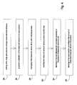
- a method of the inventioncontains the following steps:
- the parameters of a radio network modelare not varied, but the modelling values themselves are directly modified. This is effected with the modelling values of all area portions according to a certain mathematical operation. This operation directly depends on the measuring data and the position of the respective area portion.
- the method according to the inventioncan preferably be carried out by the steps:
- the mathematical operationcan comprise an interpolation.
- the value representing the value of the measured datais an (arithmetic or geometric) average value of the measured data. It may also be a weighted average value.
- modelling valuesare modelled path loss data and the measured data are path loss data determined from the receiving power of the reference signals emitted by the radio cell of a radio network.
- the values representing the values of modelling data and measured dataare here also average values.
- a device for carrying out the described method with a data base storing a virtual radio network model with position dependent modelling values, a measuring device for the generation of position dependent measured data of the modelled real radio network at measuring positionsis, according to the present invention, characterized by data processing means adapted to modify each of the modelling values directly according to the measured data by a mathematical operation by adapting the modelling values to the measured values.
- FIG. 3Is a block diagram and shows the entire procedure of the method according to the present invention.
- FIG. 4Is a block diagram and shows the pre-processing according to block 48 in FIG. 3 in detail;
- FIG. 6Is a block diagram and shows the local adaptation according to block 52 in FIG. 3 in detail;
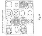
- FIG. 8Is a schematic view and shows the course of the interpolation functions decreasing to all sides from the reference points in the form of contours.
- numeral 10denotes a fine grid dividing a radio cell of a radio network into a pattern of small area portions 12 .
- a value of a modelling variableis attributed to each area portion 12 .
- These modelling valuesare, for example, defined by path loss data. Path loss data represent the fading of the sending power emitted by a sending station in the direction of the respective area portion in a radio channel up to the respective area portion 12 .
- the modelling values attributed to the area portion 12are indicated by points 14 .
- the modelling valuesare obtained from a channel model. At first, this channel model has been developed in the form of a mathematical model considering the different influences, such as distance, topography of the landscape, buildings and plants etc. also using empirically found relationships. The channel model normally does not yet coincide with the reality.
- measurementsare carried out of the real values of the modelling variable or a physical variable derived from the modelling variable, for example the receiving power obtained from the path loss data along a path 16 .
- This pathcan be, for example, a street where a measuring vehicle drives along. This leads to position dependent measured data represented by dots 18 in FIG. 1 .
- a rough grid 20is superimposed on the fine grid 10 .
- the rough grid 20divides the radio cell into regions 22 .
- Each of these regions 22comprises a large amount of small area portions 12 .
- a reference point 24is set in each of these regions 22 . It is useful if the reference points 24 are the centers of the essentially square regions 22 .
- a global correction of a displacement of the modelling values of the entire radio cellis effected.
- the average values of the measured values on one hand and the average values of the modelling values on the other handare formed for the entire radio cell.
- the modelling valuesare all corrected by the difference of these average values.
- This stepstill allows for local deviations between the measured values and the modelling values corrected in such a way.
- a further local adaptation of the modelling valuesis effected by interpolation.
- the average measured dataare formed for each region 22 of the rough grid 20 where measured data were obtained.
- the modelling value in the center 24 of such a regionis set to a value dependent on this average value.
- the modelling values of the other area portions 12 of this regionare corrected with a function decreasing from this point with increasing distance from a center point.
- FIG. 2A device for carrying out the method is shown in FIG. 2 .
- numeral 26denotes a radio network which is schematically shown.
- a measuring device 28receives measured data from the radio network.
- the measured device 28is mobile and in this example moves along the path 16 in FIG. 1 .
- the measuring device 28can be mounted on a measuring vehicle. It may also be an end device of the radio network.
- the measuring devicecomprises a device for determining the actual position of the measuring device. This can be a satellite-navigation receiver (for example GPS) or a position finder determining the position of the measuring device by contacting several sending stations.
- the radio networkcomprises several radio cells, which may overlap. Each radio cell is provided with its own code.
- the measuring deviceresponds to these codes. Thereby the obtained measured data can be attributed to each individual overlapping radio cell.
- the measuring device 28can determine record and output the obtained measured data.
- the data of the radio network 26are stored in a data base 32 .
- FIG. 2a bidirectional interface between the data base 32 and the radio network 26 is shown.
- the data base 32communicates with a computer device 36 through a bidirectional interface 34 .
- the radio network model with modelling values in the form of radio network planning dataare stored in the storage 38 in the computer device 36 .
- a computer unit 40comprises measured data from the measuring device 28 . This is indicated by an arrow 42 .
- the computer unit 40bidirectionally communicates with the storage 38 . Therefore, it comprises the modelling values of the radio network model and the measured data.
- the computer unitcarries out the above described mathematical operations, i.e. the correction of the displacement of the modelling values with respect to the measured values and the following local correction.
- the modelling values corrected in such a wayare transferred back and stored in the data base 32 through the interface 34 .
- the computer unit 40is operated by a person whom is accustomed to the planning of a radio network and its optimization.
- radio network planning data 44for an urban area of about 53 km 2 with 66 sending stations of a UMTS-network. Each of the sending stations was provided with one to three cells each with a separate antenna.
- the antennas used in the radio cells together with its direction and further fading factorswere comprised in the radio network planning data.
- the antennaswere represented by a suitable three-dimensional model of its antenna diagram.
- the sending power of the reference or pilot signals emitted by the individual radio cells and the also emitted cell codeswere stored in the form of scrambling codes in the radio network planning data.
- the area distribution of the predicted received power of the pilot signalscould be calculated from the path losses given in the matrices also in the form of a matrix.
- These receiving power matriceshave the same grid sectioning as the path loss matrices on which they are based, i.e. in the example 25 m ⁇ 25 m.
- the present radio network planning data of the UMTS radio network measurementswere carried out with a mobile radio measuring device.
- the measuring devicewas in the position to measure the receiving power of the pilot signal, as well as to detect which radio cell emitted the respective pilot signal using the corresponding scrambling code. Furthermore the receiving position for each recorded measured value was determined with a GPS-receiver and stored also.
- a series of streetswere driven through with the mobile radio measuring device in order to make a sufficient amount of measured values 46 available for the considered area in the form of input values according to FIG. 3 .
- an average value for both of themis computed in a suitable way and afterwards compared at all measuring positions. In the present example an average deviation of more than 13.5 dB with a standard deviation of more than 11 dB was found.
- the method according to the present inventionwas implemented on a computer device so that the adaptation of the path loss matrices could be automatically achieved from the measured values.
- the input datawere pre-processed in a step 48 .
- a rough grid with a sectioning of 250m ⁇ 250mwas set in a first step 56 , the distance of two area portions of this rough grid corresponding to the average distance of two streets for which measured data were present.
- the measured valueswere geographically attributed to the respective area portions of the rough grid in step 58 and an average value was formed in step 60 for each cell. Furthermore all values attributed to a certain cell were counted altogether and for each area portion of the rough grid.
- the cell attributionwas established by the respective scrambling code.
- step 64With the entire amount of measured values per cell it was decided in step 64 , if an adaptation of the path loss matrix according to the present invention should be carried out for the respective cell. If there were not enough measured values for a cell, an adaptation was not carried out, because the measured values were not reliable enough. For some radio cells, for example, no measured values were available, because they were switched off during the measuring round and they did not emit. Consequently these cells were not used for the adaptation. Furthermore, in step 66 it was decided for each radio cell and area portion of the rough grid, if there were sufficient measured values for the local adaptation at a later stage. If the amount of measured values for a certain area portion for a certain cell was below a given minimum amount, the respective area portion was not used for the local adaptation.
- each cellfor which a sufficient amount of measured values was present, was carried out according to the flow chart in FIG. 5 .
- all measured values attributed to the respective radio cell by the scrambling codewere averaged in a step 68 cell by cell.
- the predicted receiving powers of the pilot signal at the respective measuring positionwere averaged in a step 70 for each cell and the two average values were compared to each other.
- the ratio (or in the logarithmic unit decibel it is the difference) of the two average values in step 72leads to the total displacement of the predicted values with respect to the measured values.
- the matrix value of all area portions of the fine gridis corrected by this total displacement in a step 74 .
- the local adaptation of the path loss matrixis effected in a second step in the flow chart in FIG. 6 .
- the respective center pointwas determined as a reference point in step 76 .
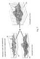
- Using the measured value displacementsa support positions an interpolation function was formed, where the sections between the support points were filled with a function decreasing with increasing distance.
- An exemplary interpolation function 88is shown in FIG.
- FIG. 8represents the contour of the exemplary interpolation function 88 .
- the ovals around the support pointscan be clearly seen, representing the decreasing with increasing distance.
- the resultis the adapted path loss matrix 92 which is shown on the right hand side in FIG. 7 , comprising the influences of the measured pilot signal receiving power of the respective cell.
- the effect of the interpolation functioncan be clearly recognized.
- the three support values 86 taken by way of examplecan be found in the form of corresponding increases 94 in the resulting path loss matrix.
- This two-step methodcan be completely carried out for all path loss matrices within only few seconds. After adapting all path loss matrices of all radio cells to the measured values in the described way another comparison of the measured data and the predicted receiving power matrices was carried out. It was found, that the average deviation could be reduced to 1.4 dB with a standard deviation of less than 9 dB.
Landscapes
- Engineering & Computer Science (AREA)
- Computer Networks & Wireless Communication (AREA)
- Signal Processing (AREA)
- Physics & Mathematics (AREA)
- Spectroscopy & Molecular Physics (AREA)
- Electromagnetism (AREA)
- Mobile Radio Communication Systems (AREA)
- Monitoring And Testing Of Transmission In General (AREA)
- Input Circuits Of Receivers And Coupling Of Receivers And Audio Equipment (AREA)
Abstract
Description
- setting a fine grid in a radio cell, defining small area portions, wherein a value of the modelling variable is attributed to each area portion by the radio network model, and
- setting mathematical operations for modifying the modelling values of all area portions of the fine grid by adapting the modelling values to the measured data,
- wherein the mathematical operations are for each area portion directly dependent on the measured data and the position of the respective area portion.
- setting a rough grid superimposed on the fine grid thereby defining areas which each comprise a plurality of area portions of the fine grid,
- obtaining measured data at measuring positions, and
- modifying the measuring values attributed to the area portions in the different areas by a mathematical operation according to the measured values of an area of the rough grid.
- summarizing the measured values at the measuring positions of one respective area of the rough grid to one value representing the general value of these measured values,
- setting a reference point within the area of the rough grid to which the value representing the measured values is attributed,
- setting an influence radius around the reference point, and
- varying the modelling values in all area portions within the influence radius according to a decreasing function of the distance of the respective area portion to the reference point.
- Obtaining measured data over the entire radio cell,
- Determining a value representing the values of such measured data,
- Forming of a value representing the values of the modelling values over the entire radio cell,
- Forming the difference of the values representing the values of measured data and modelling data, and
- Correcting the modelling values with this difference.
Claims (17)
Applications Claiming Priority (4)
| Application Number | Priority Date | Filing Date | Title |
|---|---|---|---|
| DE102004002145 | 2004-01-15 | ||
| DE102004002145.7 | 2004-01-15 | ||
| DE102004002145ADE102004002145B4 (en) | 2004-01-15 | 2004-01-15 | Method and device for adapting a radio network model to the conditions of a real radio network |
| PCT/EP2005/000134WO2005069666A1 (en) | 2004-01-15 | 2005-01-10 | Method and device for adapting a radio network model to the conditions of a real radio network |
Related Parent Applications (1)
| Application Number | Title | Priority Date | Filing Date |
|---|---|---|---|
| PCT/EP2005/000134ContinuationWO2005069666A1 (en) | 2004-01-15 | 2005-01-10 | Method and device for adapting a radio network model to the conditions of a real radio network |
Publications (2)
| Publication Number | Publication Date |
|---|---|
| US20070010204A1 US20070010204A1 (en) | 2007-01-11 |
| US7877095B2true US7877095B2 (en) | 2011-01-25 |
Family
ID=34778065
Family Applications (1)
| Application Number | Title | Priority Date | Filing Date |
|---|---|---|---|
| US11/486,951Expired - Fee RelatedUS7877095B2 (en) | 2004-01-15 | 2006-07-14 | Method and device for adapting a radio network model to the conditions of a real radio network |
Country Status (9)
| Country | Link |
|---|---|
| US (1) | US7877095B2 (en) |
| EP (1) | EP1606965B1 (en) |
| JP (1) | JP4499746B2 (en) |
| KR (1) | KR101121435B1 (en) |
| CN (1) | CN1934882B (en) |
| AT (1) | ATE441298T1 (en) |
| DE (2) | DE102004002145B4 (en) |
| ES (1) | ES2329808T3 (en) |
| WO (1) | WO2005069666A1 (en) |
Cited By (12)
| Publication number | Priority date | Publication date | Assignee | Title |
|---|---|---|---|---|
| US20090323530A1 (en)* | 2008-06-26 | 2009-12-31 | Reverb Networks | Dynamic load balancing |
| US20100105399A1 (en)* | 2007-04-04 | 2010-04-29 | Telefonaktiebolaget Lm Ericsson (Publ) | Method and Arrangement for Improved Radio Network Planning, Simulation and Analyzing in Telecommunications |
| US20110090820A1 (en)* | 2009-10-16 | 2011-04-21 | Osama Hussein | Self-optimizing wireless network |
| US20110136478A1 (en)* | 2009-12-09 | 2011-06-09 | Hafedh Trigui | Self-optimizing networks for fixed wireless access |
| US8509762B2 (en) | 2011-05-20 | 2013-08-13 | ReVerb Networks, Inc. | Methods and apparatus for underperforming cell detection and recovery in a wireless network |
| US8855675B2 (en) | 2011-12-14 | 2014-10-07 | Actix Limited | Mobile phone network management systems |
| US9008722B2 (en) | 2012-02-17 | 2015-04-14 | ReVerb Networks, Inc. | Methods and apparatus for coordination in multi-mode networks |
| US20150146550A1 (en)* | 2013-11-25 | 2015-05-28 | Motorola Solutions, Inc | Method of and system for optimizing an empirical propagation prediction model in a mobile communications network |
| US9113353B1 (en) | 2015-02-27 | 2015-08-18 | ReVerb Networks, Inc. | Methods and apparatus for improving coverage and capacity in a wireless network |
| US9258719B2 (en) | 2011-11-08 | 2016-02-09 | Viavi Solutions Inc. | Methods and apparatus for partitioning wireless network cells into time-based clusters |
| US9369886B2 (en) | 2011-09-09 | 2016-06-14 | Viavi Solutions Inc. | Methods and apparatus for implementing a self optimizing-organizing network manager |
| US9826416B2 (en) | 2009-10-16 | 2017-11-21 | Viavi Solutions, Inc. | Self-optimizing wireless network |
Families Citing this family (17)
| Publication number | Priority date | Publication date | Assignee | Title |
|---|---|---|---|---|
| EP2098086B1 (en)* | 2006-12-18 | 2014-06-04 | Telefonaktiebolaget LM Ericsson (publ) | Network configuration audit |
| FI121980B (en)* | 2007-02-16 | 2011-06-30 | Voyantic Oy | Method for characterizing a radio link |
| US8385908B2 (en)* | 2008-02-07 | 2013-02-26 | Optimi Corporation | Modifying mobile network signal propagation predictions |
| US8098590B2 (en)* | 2008-06-13 | 2012-01-17 | Qualcomm Incorporated | Apparatus and method for generating performance measurements in wireless networks |
| JP5139462B2 (en) | 2009-03-16 | 2013-02-06 | アクティックス・ゲゼルシャフト・ミト・べシュレンクテル・ハフツング | A method for approximating and optimizing the gain of capacity and coverage obtained by deploying multi-antennas in cellular radio networks |
| JP5950232B2 (en)* | 2009-06-19 | 2016-07-13 | コーダ ワイヤレス ピーティーワイ リミテッドCohda Wireless Pty Ltd | Characterization of wireless communication links |
| JP5299135B2 (en)* | 2009-07-09 | 2013-09-25 | 日本電気株式会社 | COMPUTER DEVICE, BASE STATION CONTROL DEVICE, WIRELESS COMMUNICATION SYSTEM, AND CALCULATION METHOD |
| CN102869020B (en)* | 2011-07-08 | 2015-07-29 | 中国移动通信集团湖南有限公司 | A kind of method of radio network optimization and device |
| DE102012003977A1 (en)* | 2012-02-28 | 2013-08-29 | Vodafone Holding Gmbh | Method for examining a data transport network and computer program product |
| WO2016033736A1 (en)* | 2014-09-02 | 2016-03-10 | 华为技术有限公司 | Cell selection method in wireless network, base station and user equipment |
| US20170219118A1 (en)* | 2016-01-28 | 2017-08-03 | Hamilton Sundstrand Corporation | Bleed valve position sensor |
| CN108307397A (en)* | 2017-01-13 | 2018-07-20 | 中国移动通信集团四川有限公司 | Network coverage evaluation method and system |
| US11095377B2 (en)* | 2017-12-08 | 2021-08-17 | Commscope Technologies Llc | Methods and systems for determining morphology data |
| WO2021144077A1 (en)* | 2020-01-17 | 2021-07-22 | British Telecommunications Public Limited Company | Wireless telecommunications network |
| CN113761797B (en)* | 2021-08-27 | 2023-05-23 | 北京航天晨信科技有限责任公司 | Wireless channel path loss model prediction method based on computer vision |
| CN115564180B (en)* | 2022-09-01 | 2023-10-10 | 北京京能清洁能源电力股份有限公司北京分公司 | Power network reliability assessment method based on big data analysis |
| DE102024133808B3 (en) | 2024-09-24 | 2025-09-04 | GM Global Technology Operations LLC | Measurement of the propagation conditions of high-frequency signals |
Citations (6)
| Publication number | Priority date | Publication date | Assignee | Title |
|---|---|---|---|---|
| WO1993015591A1 (en) | 1992-01-23 | 1993-08-05 | Nokia Telecommunications Oy | Method and system for planning a cellular radio network |
| US20020009992A1 (en) | 2000-07-10 | 2002-01-24 | Eric Jensen | Wireless system signal propagation collection and analysis |
| WO2002010942A1 (en) | 2000-07-28 | 2002-02-07 | Wireless Valley Communications, Inc. | System, method, and apparatus for portable design, deployment, test, and optimizaton of a communication network |
| WO2002073997A1 (en) | 2001-03-09 | 2002-09-19 | Cellular Design Services Limited | Measurement-based prediction method for radiation path loss |
| US6611500B1 (en) | 1999-11-04 | 2003-08-26 | Lucent Technologies, Inc. | Methods and apparatus for derivative-based optimization of wireless network performance |
| US20030232601A1 (en) | 2002-04-16 | 2003-12-18 | Masahiro Uno | Orthogonal frequency division multiplexing (OFDM) system with channel transfer function prediction |
Family Cites Families (3)
| Publication number | Priority date | Publication date | Assignee | Title |
|---|---|---|---|---|
| JP3709105B2 (en)* | 1999-07-23 | 2005-10-19 | 株式会社エヌ・ティ・ティ・ドコモ | Other channel communication quality estimation system using measurement channel and its communication quality estimation method |
| CN1173598C (en)* | 2001-07-14 | 2004-10-27 | 华为技术有限公司 | The Method of Adapting the Coding Mode of General Packet Radio Service to Change the Service Model |
| FR2828623B1 (en)* | 2001-08-10 | 2003-09-26 | Radiotelephone Sfr | METHOD FOR ESTABLISHING A RADIO COVERAGE CARD |
- 2004
- 2004-01-15DEDE102004002145Apatent/DE102004002145B4/ennot_activeExpired - Fee Related
- 2005
- 2005-01-10KRKR1020067016027Apatent/KR101121435B1/ennot_activeExpired - Fee Related
- 2005-01-10WOPCT/EP2005/000134patent/WO2005069666A1/enactiveApplication Filing
- 2005-01-10DEDE502005007977Tpatent/DE502005007977D1/ennot_activeExpired - Fee Related
- 2005-01-10ATAT05700777Tpatent/ATE441298T1/ennot_activeIP Right Cessation
- 2005-01-10EPEP05700777Apatent/EP1606965B1/ennot_activeExpired - Lifetime
- 2005-01-10CNCN200580008442XApatent/CN1934882B/ennot_activeExpired - Fee Related
- 2005-01-10JPJP2006548238Apatent/JP4499746B2/ennot_activeExpired - Fee Related
- 2005-01-10ESES05700777Tpatent/ES2329808T3/ennot_activeExpired - Lifetime
- 2006
- 2006-07-14USUS11/486,951patent/US7877095B2/ennot_activeExpired - Fee Related
Patent Citations (8)
| Publication number | Priority date | Publication date | Assignee | Title |
|---|---|---|---|---|
| WO1993015591A1 (en) | 1992-01-23 | 1993-08-05 | Nokia Telecommunications Oy | Method and system for planning a cellular radio network |
| US5561841A (en)* | 1992-01-23 | 1996-10-01 | Nokia Telecommunication Oy | Method and apparatus for planning a cellular radio network by creating a model on a digital map adding properties and optimizing parameters, based on statistical simulation results |
| US6611500B1 (en) | 1999-11-04 | 2003-08-26 | Lucent Technologies, Inc. | Methods and apparatus for derivative-based optimization of wireless network performance |
| US20020009992A1 (en) | 2000-07-10 | 2002-01-24 | Eric Jensen | Wireless system signal propagation collection and analysis |
| WO2002010942A1 (en) | 2000-07-28 | 2002-02-07 | Wireless Valley Communications, Inc. | System, method, and apparatus for portable design, deployment, test, and optimizaton of a communication network |
| WO2002073997A1 (en) | 2001-03-09 | 2002-09-19 | Cellular Design Services Limited | Measurement-based prediction method for radiation path loss |
| US20040116111A1 (en) | 2001-03-09 | 2004-06-17 | Simon Saunders | Measurement based prediction method for radiation path loss |
| US20030232601A1 (en) | 2002-04-16 | 2003-12-18 | Masahiro Uno | Orthogonal frequency division multiplexing (OFDM) system with channel transfer function prediction |
Cited By (20)
| Publication number | Priority date | Publication date | Assignee | Title |
|---|---|---|---|---|
| US20100105399A1 (en)* | 2007-04-04 | 2010-04-29 | Telefonaktiebolaget Lm Ericsson (Publ) | Method and Arrangement for Improved Radio Network Planning, Simulation and Analyzing in Telecommunications |
| US8768368B2 (en)* | 2007-04-04 | 2014-07-01 | Telefonaktiebolaget L M Ericsson (Publ) | Method and arrangement for improved radio network planning, simulation and analyzing in telecommunications |
| US8498207B2 (en) | 2008-06-26 | 2013-07-30 | Reverb Networks | Dynamic load balancing |
| US20090323530A1 (en)* | 2008-06-26 | 2009-12-31 | Reverb Networks | Dynamic load balancing |
| US9826420B2 (en) | 2009-10-16 | 2017-11-21 | Viavi Solutions Inc. | Self-optimizing wireless network |
| US8665835B2 (en) | 2009-10-16 | 2014-03-04 | Reverb Networks | Self-optimizing wireless network |
| US20110090820A1 (en)* | 2009-10-16 | 2011-04-21 | Osama Hussein | Self-optimizing wireless network |
| US9226178B2 (en) | 2009-10-16 | 2015-12-29 | Reverb Networks | Self-optimizing wireless network |
| US9826416B2 (en) | 2009-10-16 | 2017-11-21 | Viavi Solutions, Inc. | Self-optimizing wireless network |
| US8385900B2 (en) | 2009-12-09 | 2013-02-26 | Reverb Networks | Self-optimizing networks for fixed wireless access |
| US20110136478A1 (en)* | 2009-12-09 | 2011-06-09 | Hafedh Trigui | Self-optimizing networks for fixed wireless access |
| US8509762B2 (en) | 2011-05-20 | 2013-08-13 | ReVerb Networks, Inc. | Methods and apparatus for underperforming cell detection and recovery in a wireless network |
| US9369886B2 (en) | 2011-09-09 | 2016-06-14 | Viavi Solutions Inc. | Methods and apparatus for implementing a self optimizing-organizing network manager |
| US10003981B2 (en) | 2011-11-08 | 2018-06-19 | Viavi Solutions Inc. | Methods and apparatus for partitioning wireless network cells into time-based clusters |
| US9258719B2 (en) | 2011-11-08 | 2016-02-09 | Viavi Solutions Inc. | Methods and apparatus for partitioning wireless network cells into time-based clusters |
| US8855675B2 (en) | 2011-12-14 | 2014-10-07 | Actix Limited | Mobile phone network management systems |
| US9008722B2 (en) | 2012-02-17 | 2015-04-14 | ReVerb Networks, Inc. | Methods and apparatus for coordination in multi-mode networks |
| US9271157B2 (en)* | 2013-11-25 | 2016-02-23 | Motorola Solutions, Inc. | Method of and system for optimizing an empirical propagation prediction model in a mobile communications network |
| US20150146550A1 (en)* | 2013-11-25 | 2015-05-28 | Motorola Solutions, Inc | Method of and system for optimizing an empirical propagation prediction model in a mobile communications network |
| US9113353B1 (en) | 2015-02-27 | 2015-08-18 | ReVerb Networks, Inc. | Methods and apparatus for improving coverage and capacity in a wireless network |
Also Published As
| Publication number | Publication date |
|---|---|
| DE102004002145A1 (en) | 2005-10-06 |
| DE502005007977D1 (en) | 2009-10-08 |
| CN1934882B (en) | 2010-05-12 |
| WO2005069666A1 (en) | 2005-07-28 |
| KR101121435B1 (en) | 2012-03-16 |
| DE102004002145B4 (en) | 2007-11-22 |
| KR20070000477A (en) | 2007-01-02 |
| EP1606965B1 (en) | 2009-08-26 |
| JP2007525879A (en) | 2007-09-06 |
| CN1934882A (en) | 2007-03-21 |
| ATE441298T1 (en) | 2009-09-15 |
| JP4499746B2 (en) | 2010-07-07 |
| ES2329808T3 (en) | 2009-12-01 |
| EP1606965A1 (en) | 2005-12-21 |
| US20070010204A1 (en) | 2007-01-11 |
Similar Documents
| Publication | Publication Date | Title |
|---|---|---|
| US7877095B2 (en) | Method and device for adapting a radio network model to the conditions of a real radio network | |
| Rautiainen et al. | Verifying path loss and delay spread predictions of a 3D ray tracing propagation model in urban environment | |
| KR20060136447A (en) | Method and device for adapting a radio network model to the conditions of a real radio network | |
| JP4537584B2 (en) | Method and apparatus for measuring and predicting radio conditions in a communication system | |
| US7146298B2 (en) | System and method for wireless location performance prediction | |
| US6097957A (en) | Radiotelephone service planning system and method for determining a best server for a communication connection | |
| AU745566B2 (en) | Method of locating terminal, and cellular radio system | |
| US7212822B1 (en) | Method and techniques for penalty-based channel assignments in a cellular network | |
| WO1998015149A1 (en) | A method of locating a mobile station | |
| US7177653B2 (en) | Mobile user position locating system | |
| US20130281100A1 (en) | Method for the prediction of coverage areas of a cellular network | |
| JP2003078481A (en) | Method for establishing radio coverage map | |
| US20030069027A1 (en) | Location method for mobile networks | |
| MXPA02007530A (en) | Method and apparatus for simulating and planning of wireless position location networks. | |
| CN103635826A (en) | Method and apparatus for geo-locating mobile station | |
| US6640089B1 (en) | System and method for adaptively predicting radio wave propagation | |
| US6389294B1 (en) | Method of determining effect of radio wave multipath fading | |
| JP3862021B2 (en) | Radio wave propagation simulator | |
| US6181917B1 (en) | Method and system for designing a cellular communication system | |
| US6665542B1 (en) | System and method for cumulative clutter path loss | |
| CN106796277B (en) | Location adjustment in a mobile communication network | |
| US8188995B2 (en) | Methods and appratus for estimating cell radius in a mobile telecommunications network | |
| KR100641330B1 (en) | Simulation method for wireless network performance analysis | |
| KR960011868B1 (en) | How to Configure a Mobile Cell | |
| EP4055863B1 (en) | Wireless telecommunications network |
Legal Events
| Date | Code | Title | Description |
|---|---|---|---|
| AS | Assignment | Owner name:RADIOPLAN GMBH, GERMANY Free format text:ASSIGNMENT OF ASSIGNORS INTEREST;ASSIGNOR:HUBNER, JOHANNES & HUNOLD, DIETRICH;REEL/FRAME:018332/0805 Effective date:20060720 | |
| AS | Assignment | Owner name:ACTIX GMBH, GERMANY Free format text:CHANGE OF NAME;ASSIGNOR:RADIOPLAN GMBH;REEL/FRAME:025641/0102 Effective date:20070625 | |
| STCF | Information on status: patent grant | Free format text:PATENTED CASE | |
| AS | Assignment | Owner name:ACTIX GMBH, GERMANY Free format text:CHANGE OF NAME;ASSIGNOR:RADIOPLAN GMBH;REEL/FRAME:025642/0720 Effective date:20070625 | |
| FEPP | Fee payment procedure | Free format text:PAT HOLDER NO LONGER CLAIMS SMALL ENTITY STATUS, ENTITY STATUS SET TO UNDISCOUNTED (ORIGINAL EVENT CODE: STOL); ENTITY STATUS OF PATENT OWNER: LARGE ENTITY | |
| FPAY | Fee payment | Year of fee payment:4 | |
| MAFP | Maintenance fee payment | Free format text:PAYMENT OF MAINTENANCE FEE, 8TH YEAR, LARGE ENTITY (ORIGINAL EVENT CODE: M1552) Year of fee payment:8 | |
| FEPP | Fee payment procedure | Free format text:MAINTENANCE FEE REMINDER MAILED (ORIGINAL EVENT CODE: REM.); ENTITY STATUS OF PATENT OWNER: LARGE ENTITY | |
| LAPS | Lapse for failure to pay maintenance fees | Free format text:PATENT EXPIRED FOR FAILURE TO PAY MAINTENANCE FEES (ORIGINAL EVENT CODE: EXP.); ENTITY STATUS OF PATENT OWNER: LARGE ENTITY | |
| STCH | Information on status: patent discontinuation | Free format text:PATENT EXPIRED DUE TO NONPAYMENT OF MAINTENANCE FEES UNDER 37 CFR 1.362 | |
| FP | Lapsed due to failure to pay maintenance fee | Effective date:20230125 |