US7876066B2 - Multi-component charging station with surge protector - Google Patents
Multi-component charging station with surge protectorDownload PDFInfo
- Publication number
- US7876066B2 US7876066B2US12/636,360US63636009AUS7876066B2US 7876066 B2US7876066 B2US 7876066B2US 63636009 AUS63636009 AUS 63636009AUS 7876066 B2US7876066 B2US 7876066B2
- Authority
- US
- United States
- Prior art keywords
- base
- tray
- charging station
- base cover
- perimeter wall
- Prior art date
- Legal status (The legal status is an assumption and is not a legal conclusion. Google has not performed a legal analysis and makes no representation as to the accuracy of the status listed.)
- Expired - Fee Related
Links
- 230000001012protectorEffects0.000titleclaimsabstractdescription24
- 230000001105regulatory effectEffects0.000claimsdescription2
- 230000000284resting effectEffects0.000claims4
- 230000008901benefitEffects0.000description8
- 238000007373indentationMethods0.000description7
- 238000000034methodMethods0.000description5
- OJIJEKBXJYRIBZ-UHFFFAOYSA-Ncadmium nickelChemical compound[Ni].[Cd]OJIJEKBXJYRIBZ-UHFFFAOYSA-N0.000description1
- 238000010276constructionMethods0.000description1
Images


Classifications
- H—ELECTRICITY
- H02—GENERATION; CONVERSION OR DISTRIBUTION OF ELECTRIC POWER
- H02J—CIRCUIT ARRANGEMENTS OR SYSTEMS FOR SUPPLYING OR DISTRIBUTING ELECTRIC POWER; SYSTEMS FOR STORING ELECTRIC ENERGY
- H02J7/00—Circuit arrangements for charging or depolarising batteries or for supplying loads from batteries
- H02J7/0042—Circuit arrangements for charging or depolarising batteries or for supplying loads from batteries characterised by the mechanical construction
Definitions
- This inventionrelates generally to multi-component charging stations with surge protectors for charging and protecting portable electronic devices.
- rechargeable batterieshave found wide utility in powering contemporary consumer and business products.
- nickel cadmium batteriesmay be used to energize portable electronic devices and then repeatedly recharged and reused.
- Rechargeable batteriesare typically recharged by plugging an AC-powered charger unit into the portable electronic device and into an AC power wall receptacle.
- the AC-powered charger unittypically converts 110 or 120 volt AC current from an outlet to low voltage DC power used to recharge the batteries.
- the present inventionis a multi-component charging station.
- the charging stationincludes a top removable tray for holding electronic devices, such as telephones, pagers, personal digital assistants (PDAs), wireless e-mail devices, digital cameras, mp3 players.
- the traycan also hold and the charging station can also power battery charging units that are separate from the portable electronic devices.
- the tray of the multi-component charging stationis substantially flat to receive and hold a variety of objects.
- the tray portion of the battery charging stationhas a raised perimeter wall to prevent objects placed on the tray from falling off.
- the charging stationalso includes a base that houses a surge protector having multiple AC outlets.
- the surge protector within the basecan power multiple charger units at once and protect the units from surges or spikes in power.
- the basecan be covered by a removable base cover.
- the base coveris particularly useful when the tray and base are positioned separately. For example, the tray holding the portable electronic devices and other small objects can be placed on a table, while the base is placed on the floor. Then, the base cover can be placed on top of the base to conceal the surge protector, outlets, and the charger units.
- the charging stationcontains an opening that leads to the interior space of the base.
- the openingcan be located in the base cover, in the tray or in the base part.
- the openingpermits at least one portable electronic device to be connected to its associated charger unit plugged into the surge protector within the interior space.
- a second openingis located within the charging station to permit the surge protector to be plugged into an external outlet.
- the opening located within the charging stationis fitted with a grommet.
- the grommethas multiple openings that permit the cord from each charger unit to connect to its associated electronic device through one of the openings in the grommet and the opening in the charging station to the electronic device located on the tray.
- the perimeter wall of the traycontains at least one indentation extending from the interior surface of the perimeter wall to the outer surface of the perimeter wall.
- the perimeter wall of the traycontains at least one indentation extending from the interior surface of the perimeter wall to an opening in the perimeter wall that leads to the surge protector and outlet within the interior space.
- the charging stationis integrated as a universal serial bus (USB) hub.
- USBuniversal serial bus
- the charging stationis integrated with a circuit breaker switch.
- the charging stationis integrated with at least one additional outlet.
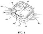
- FIG. 1is an illustration of a charging station positioned on a table according to a preferred embodiment of the invention
- FIG. 2is an illustration of the base of the charging station according to a preferred embodiment of the invention.
- FIG. 3is an illustration of the base and base cover of the charging station according to a preferred embodiment of the invention.
- FIG. 4is an illustration of a charging station with an external outlet according to another preferred embodiment of the invention.
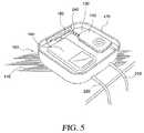
- FIG. 5is an illustration of the tray of the charging station according to a preferred embodiment of the invention.
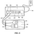
- FIG. 6is an illustration of base and tray of the charging station with an external outlet according to a preferred embodiment of the invention.
- the multi-component charging stationallows a plurality of rechargeable portable electronic devices to be connected to AC-powered charger units for recharging either individually or simultaneously by placing the electronic devices on the tray of the multi-component charging station.
- the charger unit cord for each portable electronic deviceis then fed through at least one opening within the charging station from an AC outlet protected by a surge protector within the interior space of the charging station to the associated portable electronic device.
- portable electronic devicesinclude, but are not limited to mobile phones, personal digital assistants (PDAs), digital cameras, mp3 players, CD players, cassette players, pagers, walkie talkies, gaming systems, and other rechargeable electronic devices. Because of the open tray feature, the present invention allows multiple electronic devices to be recharged or stored simultaneously and virtually any type of portable electronic device can be recharged. Further, the present invention allows for the storage of other small objects that do not need to be recharged, such a wallet or keys.
- FIG. 1is a top view of a charging station 100 according to a preferred embodiment of the invention positioned on top of a surface 110 , such as a table.
- charging station 100has multi-components.
- the tray 130is placed on top of the base 140 .
- a base cover 190can also be placed between the tray 130 and the base 140 .
- the tray 130is capable of storing portable electronic devices, including, for example, a mobile telephone 150 and an mp3 player 160 .
- the tray 130has a raised perimeter wall 170 that prevents objects that are positioned on the tray 130 from falling off.
- FIG. 2is an illustration of the base 140 of the charging station 100 according to a preferred embodiment of the invention.
- the base 140houses a surge protector 180 which is powered by AC power provided from a 110 or 120 volt outlet 182 through a power cord 183 .
- the surge protector 180can provide power through multiple outlets 182 in the base.
- Each outlet 182is capable of receiving a charger unit 184 .
- the charging station 100can charge multiple devices at once and protects the devices from surges or spikes in power.
- the outlets 182are sufficiently spaced apart to accept AC adaptor blocks.
- the outlets 182are repositionable via a short pigtail cord to accept AC adaptor blocks.
- FIG. 3is an illustration of the base 140 and base cover 190 . As illustrated in FIG. 3 , a base cover can be placed on top of the base to enclose an interior space 200 and conceal the surge protector 180 .
- FIG. 4is an illustration of the charging station 100 .
- the tray 130 and preferably the perimeter wall 170 of the tray 130has a first opening 185 .
- the first opening 185permits the charger cord for at least one portable electronic device, for example, as illustrated in FIG. 4 , the mobile phone charger cord 210 and mp3 charger cord 220 to be fed through the first opening 185 from the interior space 200 within the base 140 where the charger unit 184 is connected to the surge protector 180 .
- FIG. 3there is preferably a second opening 230 in the base cover 190 .
- the second opening 230allows charger cords, for example the mobile phone charger cord 210 and mp3 charger cord 220 to be fed through the second opening from the interior space 200 within the base 140 where the charger units 184 are connected to the surge protector 180 .
- a grommet 240can be inserted into the first opening 185 .
- the grommet 240can be used to provide support for the charger cords, for example the mobile phone charger cord 210 and mp3 charger cord 220 illustrated in FIG. 4 , so that the mobile phone charger cord 210 and mp3 charger cord 220 can easily fit through the first opening 185 .
- the grommet 240can also serve as a decorative feature.
- the grommet 240can have multiple openings. Each opening can serve to permit access of one charger cord from the interior space 200 within the base 140 to the tray.
- a second grommetcan also be utilized for the second opening 230 within the base cover 190 . Such a second grommet is particularly useful if the base cover 190 is being utilized and will not be covered by the tray 130 .
- FIG. 5 and FIG. 6are illustrations of the tray 130 of an unassembled charging station 100 .
- the tray 130 portion of the charging station 100can be used separately from the remainder of the charging station 100 , specifically the base 140 and if desired, the base cover 190 .
- the tray 130 holding at least one portable electronic device, as illustrated in FIG. 5 , the mobile phone 150 and mp3 player 160can be place on a surface 110 , such as a table, while the base 140 , as illustrated in FIG. 2 is positioned on a second surface 250 , such as the floor. If the charging station 100 is used in this manner, the charger cords, as illustrated in the FIG.
- the base cover 190is can be particularly useful when the tray 130 and base 140 are located on separate surfaces.
- the base cover 190can be used on top of the base 140 to hide the surge protector 180 and charger units 184 .
- the tray 130 or base 140be placed on other surfaces, other than a table or floor, or other locations on the same surface, the multi-functional aspect to the disclosed invention permits such flexibility.
- the base cover 190can be affixed to the base 140 using a closure mechanism, including but not limited to resilient interference means or a locking mechanism.
- the tray 130can be affixed to the base 140 or base cover 190 using a closure mechanism, including but not limited to resilient interference means or a locking mechanism.
- the perimeter wall 170 of the traycontains at least one indentation that runs from the inner surface of the perimeter wall 170 to the outer surface of the perimeter wall 170 .
- the charger cord from the electronic devicecan be placed within the indentation.
- the perimeter wall 170contains at least one indentation that runs from the inner surface of the perimeter wall 170 to an opening in the perimeter wall 170 .
- the charger cord from the electronic devicecan extend from the interior space in the base 140 , to the opening, along the indentation to the top of the tray 130 .
- the charging station 100can be integrated with additional features such as with a USB hub, a circuit breaker switch 260 , and/or at least one additional outlet 270 accessible from the exterior of the base to permit other electrical devices to be powered.
- the charging station 100 of the present inventioneliminates the need for multiple charging stations or modules.
- the charging station 100 according to the present inventionprovides a distinct advantage over prior art systems because it is designed to be used with a plurality of portable electronic devices or battery charging units and is not limited to being used with a specific electronic device or battery charging units. Because of the structure the charging station 100 and particularly the tray 130 feature, a plurality of portable electronic devices, regardless of size or shape can be simultaneously or individually, stored and recharged.
- the present inventionprovides, a charging station for receiving a portable electronic device and a charger unit for charging a portable electronic device.
- the charging stationcomprises a base, a generally planar base cover and a tray.
- the basecomprises a generally planar bottom surface bounded by a perimeter wall.
- the base coveris removably attached to the upper portion of the perimeter wall of the base to enclose an interior space for housing a surge protector and a charger unit powered by the surge protector.
- the base coveralso has an opening to permit a charger cord extending from a charger unit located within the interior space to pass through the base cover.
- the traycomprises a generally planar surface for receiving at least one portable electronic device.
- the trayis configured for removable attachment to the upper surface of the base cover.
- the trayalso has an opening to permit a charger cord to pass through the tray.
- a surge protectoris located within the interior space comprising outlets for providing regulated power to a charger unit for charging a portable electronic device.
- embodiments and limitations disclosed hereinare not dedicated to the public under the doctrine of dedication if the embodiments and/or limitations: (1) are not expressly claimed in the claims; and (2) are or are potentially equivalents of express elements and/or limitations in the claims under the doctrine of equivalents.
Landscapes
- Engineering & Computer Science (AREA)
- Power Engineering (AREA)
- Charge And Discharge Circuits For Batteries Or The Like (AREA)
Abstract
Description
Claims (20)
Priority Applications (2)
| Application Number | Priority Date | Filing Date | Title |
|---|---|---|---|
| US12/636,360US7876066B2 (en) | 2005-06-08 | 2009-12-11 | Multi-component charging station with surge protector |
| US12/652,740US20100171465A1 (en) | 2005-06-08 | 2010-01-05 | Charging Station Configured To Provide Electrical Power to Electronic Devices And Method Therefor |
Applications Claiming Priority (2)
| Application Number | Priority Date | Filing Date | Title |
|---|---|---|---|
| US11/147,676US7652452B2 (en) | 2005-06-08 | 2005-06-08 | Multi-component charging station with surge protector |
| US12/636,360US7876066B2 (en) | 2005-06-08 | 2009-12-11 | Multi-component charging station with surge protector |
Related Parent Applications (1)
| Application Number | Title | Priority Date | Filing Date |
|---|---|---|---|
| US11/147,676ContinuationUS7652452B2 (en) | 2005-06-08 | 2005-06-08 | Multi-component charging station with surge protector |
Related Child Applications (1)
| Application Number | Title | Priority Date | Filing Date |
|---|---|---|---|
| US12/652,740Continuation-In-PartUS20100171465A1 (en) | 2005-06-08 | 2010-01-05 | Charging Station Configured To Provide Electrical Power to Electronic Devices And Method Therefor |
Publications (2)
| Publication Number | Publication Date |
|---|---|
| US20100090646A1 US20100090646A1 (en) | 2010-04-15 |
| US7876066B2true US7876066B2 (en) | 2011-01-25 |
Family
ID=37524216
Family Applications (2)
| Application Number | Title | Priority Date | Filing Date |
|---|---|---|---|
| US11/147,676Expired - Fee RelatedUS7652452B2 (en) | 2005-06-08 | 2005-06-08 | Multi-component charging station with surge protector |
| US12/636,360Expired - Fee RelatedUS7876066B2 (en) | 2005-06-08 | 2009-12-11 | Multi-component charging station with surge protector |
Family Applications Before (1)
| Application Number | Title | Priority Date | Filing Date |
|---|---|---|---|
| US11/147,676Expired - Fee RelatedUS7652452B2 (en) | 2005-06-08 | 2005-06-08 | Multi-component charging station with surge protector |
Country Status (1)
| Country | Link |
|---|---|
| US (2) | US7652452B2 (en) |
Cited By (8)
| Publication number | Priority date | Publication date | Assignee | Title |
|---|---|---|---|---|
| US20110221129A1 (en)* | 2010-03-12 | 2011-09-15 | Sisson Anthony M | Board Game System With Integral Docking System |
| US20130003291A1 (en)* | 2011-06-28 | 2013-01-03 | Hon Hai Precision Industry Co., Ltd. | Docking station for electronic device |
| US20130113420A1 (en)* | 2012-10-02 | 2013-05-09 | John L. Majoris, JR. | Universal Station for Organizing and Charging Multiple Electronic Devices |
| US20170264117A1 (en)* | 2016-03-09 | 2017-09-14 | Constellation Marketing Services, Inc. | Housing with multiple mobile electronic device charging stations and a display |
| US9912154B2 (en) | 2009-09-25 | 2018-03-06 | Pucline, Llc | Electrical power supplying device having a central power-receptacle assembly with a penisula-like housing structure supplying electrical power to power plugs, adaptors and modules while concealed from view during power supplying operations |
| US9927837B2 (en) | 2013-07-03 | 2018-03-27 | Pucline, Llc | Electrical power supplying system having an electrical power supplying docking station with a multi-function module for use in diverse environments |
| US10033207B2 (en)* | 2012-02-09 | 2018-07-24 | JPM Networks LLC | Mobile device charging stations and methods for making same |
| US10063958B2 (en) | 2014-11-07 | 2018-08-28 | Microsoft Technology Licensing, Llc | Earpiece attachment devices |
Families Citing this family (22)
| Publication number | Priority date | Publication date | Assignee | Title |
|---|---|---|---|---|
| JP4789596B2 (en)* | 2005-11-21 | 2011-10-12 | トヨタ自動車株式会社 | Harness wiring structure |
| US7909161B2 (en)* | 2007-07-31 | 2011-03-22 | Belkin International, Inc. | Case configured to hold portable computer and method of manufacturing and using the same |
| USD591080S1 (en) | 2008-03-24 | 2009-04-28 | For Your Ease Only, Inc. | Swivel charging station |
| US20100176762A1 (en)* | 2009-01-13 | 2010-07-15 | Daymude E Andrew | Vertical Charging Apparatus |
| US20100213892A1 (en) | 2009-02-23 | 2010-08-26 | Desanctis Jeanne | Portable docking station for powering multiple AC-powered battery chargers and multiple DC-powered battery chargers simultaneously |
| US20100231161A1 (en)* | 2009-03-12 | 2010-09-16 | Wendell Brown | Apparatus for Storing and Charging Electronic Devices |
| US20100308187A1 (en)* | 2009-06-04 | 2010-12-09 | Pi-Fen Lin | Integrated magnetic device and a magnetic board thereof |
| US8922329B2 (en)* | 2009-07-23 | 2014-12-30 | Qualcomm Incorporated | Battery charging to extend battery life and improve efficiency |
| US8173893B2 (en)* | 2010-05-28 | 2012-05-08 | Yao-Hung Huang | Electronic device case |
| US11134580B2 (en) | 2010-07-08 | 2021-09-28 | Zagg Inc | Protective cover for portable electronic device and associated systems and methods |
| USD674798S1 (en)* | 2010-09-30 | 2013-01-22 | Samsung Electronics Co., Ltd. | Mobile terminal case |
| US9218024B2 (en) | 2011-06-23 | 2015-12-22 | Zagg Intellectual Property Holding Co., Inc. | Accessory and support for electronic devices, systems including the same and methods |
| US8742720B2 (en) | 2011-07-22 | 2014-06-03 | Owens Products, Inc. | Charging station |
| USD696625S1 (en)* | 2013-05-07 | 2013-12-31 | Eric Beare Associates Limited | Charger |
| US9337676B2 (en)* | 2014-01-07 | 2016-05-10 | Joseph Benigno | Outlet enclosure for device chargers |
| US20140203757A1 (en)* | 2014-03-14 | 2014-07-24 | Svetlana Ibragimova | Decorative object with a charging device |
| US20160134140A1 (en)* | 2014-11-07 | 2016-05-12 | John Tittle | Charging Station |
| CN105896685B (en)* | 2016-06-20 | 2018-11-23 | 扬州杭集工业园经济发展有限公司 | A kind of omnipotent charger baby |
| CN207368677U (en)* | 2017-04-27 | 2018-05-15 | 深圳市储能电子有限公司 | A kind of multi-functional charging case |
| JP1663855S (en)* | 2019-06-05 | 2020-07-20 | ||
| US12207715B2 (en)* | 2021-12-22 | 2025-01-28 | Yondr, Inc. | Electronics storage system |
| US20240074601A1 (en)* | 2022-09-01 | 2024-03-07 | Wolf 1834 | Travel watch stand |
Citations (7)
| Publication number | Priority date | Publication date | Assignee | Title |
|---|---|---|---|---|
| US5836212A (en)* | 1997-05-21 | 1998-11-17 | Teleflex, Inc. | Interlocking grommet with gross hole and method of assembly |
| US6218796B1 (en)* | 1998-10-06 | 2001-04-17 | Mobile Design Corporation | Storage cart for rechargeable devices |
| US20020096509A1 (en)* | 2000-12-06 | 2002-07-25 | Mosshaim Innovations, Inc. | Catering trolley |
| JP2004135904A (en)* | 2002-10-18 | 2004-05-13 | Itoki Crebio Corp | Rack device |
| US6844494B1 (en)* | 2004-03-15 | 2005-01-18 | Jason Nevins | Organizer for use in the charging of electrically operated consumer products |
| US7038126B2 (en)* | 2002-06-25 | 2006-05-02 | Jo Solet | Cable/wire and electronic device storage container |
| US7189106B2 (en)* | 2005-05-17 | 2007-03-13 | Young Eric D | Electric adapter organizer |
Family Cites Families (2)
| Publication number | Priority date | Publication date | Assignee | Title |
|---|---|---|---|---|
| DE4036374A1 (en)* | 1990-11-15 | 1992-05-21 | Bsg Schalttechnik | CHARGING DEVICE FOR RECHARGEABLE BATTERIES |
| JP2005051827A (en)* | 2003-07-29 | 2005-02-24 | Toshiro Tateishi | Charger stand |
- 2005
- 2005-06-08USUS11/147,676patent/US7652452B2/ennot_activeExpired - Fee Related
- 2009
- 2009-12-11USUS12/636,360patent/US7876066B2/ennot_activeExpired - Fee Related
Patent Citations (7)
| Publication number | Priority date | Publication date | Assignee | Title |
|---|---|---|---|---|
| US5836212A (en)* | 1997-05-21 | 1998-11-17 | Teleflex, Inc. | Interlocking grommet with gross hole and method of assembly |
| US6218796B1 (en)* | 1998-10-06 | 2001-04-17 | Mobile Design Corporation | Storage cart for rechargeable devices |
| US20020096509A1 (en)* | 2000-12-06 | 2002-07-25 | Mosshaim Innovations, Inc. | Catering trolley |
| US7038126B2 (en)* | 2002-06-25 | 2006-05-02 | Jo Solet | Cable/wire and electronic device storage container |
| JP2004135904A (en)* | 2002-10-18 | 2004-05-13 | Itoki Crebio Corp | Rack device |
| US6844494B1 (en)* | 2004-03-15 | 2005-01-18 | Jason Nevins | Organizer for use in the charging of electrically operated consumer products |
| US7189106B2 (en)* | 2005-05-17 | 2007-03-13 | Young Eric D | Electric adapter organizer |
Cited By (12)
| Publication number | Priority date | Publication date | Assignee | Title |
|---|---|---|---|---|
| US9912154B2 (en) | 2009-09-25 | 2018-03-06 | Pucline, Llc | Electrical power supplying device having a central power-receptacle assembly with a penisula-like housing structure supplying electrical power to power plugs, adaptors and modules while concealed from view during power supplying operations |
| US20110221129A1 (en)* | 2010-03-12 | 2011-09-15 | Sisson Anthony M | Board Game System With Integral Docking System |
| US20130003291A1 (en)* | 2011-06-28 | 2013-01-03 | Hon Hai Precision Industry Co., Ltd. | Docking station for electronic device |
| US8553407B2 (en)* | 2011-06-28 | 2013-10-08 | Fu Tai Hua Industry (Shenzhen) Co., Ltd. | Docking station for electronic device |
| US10033207B2 (en)* | 2012-02-09 | 2018-07-24 | JPM Networks LLC | Mobile device charging stations and methods for making same |
| US10141757B2 (en) | 2012-02-09 | 2018-11-27 | JPM Networks LLC | Mobile device charging stations and methods for making same |
| US20130113420A1 (en)* | 2012-10-02 | 2013-05-09 | John L. Majoris, JR. | Universal Station for Organizing and Charging Multiple Electronic Devices |
| US9927837B2 (en) | 2013-07-03 | 2018-03-27 | Pucline, Llc | Electrical power supplying system having an electrical power supplying docking station with a multi-function module for use in diverse environments |
| US11150697B2 (en) | 2013-07-03 | 2021-10-19 | Pucline Llc | Multi-function electrical power supplying station with dockable station supporting emergency lighting, portable lighting, and consumer device battery recharging modes of operation |
| US11614784B2 (en) | 2013-07-03 | 2023-03-28 | Pucline, Llc | Electrical power supplying and cord management station with dockable module supporting multiple modes of operation |
| US10063958B2 (en) | 2014-11-07 | 2018-08-28 | Microsoft Technology Licensing, Llc | Earpiece attachment devices |
| US20170264117A1 (en)* | 2016-03-09 | 2017-09-14 | Constellation Marketing Services, Inc. | Housing with multiple mobile electronic device charging stations and a display |
Also Published As
| Publication number | Publication date |
|---|---|
| US20060280519A1 (en) | 2006-12-14 |
| US20100090646A1 (en) | 2010-04-15 |
| US7652452B2 (en) | 2010-01-26 |
Similar Documents
| Publication | Publication Date | Title |
|---|---|---|
| US7876066B2 (en) | Multi-component charging station with surge protector | |
| US20100171465A1 (en) | Charging Station Configured To Provide Electrical Power to Electronic Devices And Method Therefor | |
| EP3576247A1 (en) | Systems and methods for charging one or more electronic devices | |
| US10243377B2 (en) | Portable multiple mobile electronic device charging station | |
| US8183825B2 (en) | Docking charger for charging a hand held electronic device with or without a protective cover case fitted thereon | |
| US9425632B2 (en) | Utility bags with battery pack-to-universal serial bus power devices | |
| US20120098493A1 (en) | Charging station | |
| US20090015192A1 (en) | Portable-electric-appliance protector/power supplier | |
| US20080272258A1 (en) | Device for rechargeable electrical apparatus retainer unit | |
| US20160134142A1 (en) | Portable device case having integrated wireless charging station | |
| US20070285049A1 (en) | Jump starter with built-in battery charger | |
| US20090115367A1 (en) | Portable battery DC charger | |
| US20150180247A1 (en) | Portable Device Charger | |
| WO2008143804A2 (en) | Portable battery powered power supply | |
| GB2426863A (en) | A device for electrical power supply to a power tool | |
| EP2653053A1 (en) | Solar powered cases | |
| US20060202702A1 (en) | Headset charging system with interchargeable charge devices | |
| KR200488549Y1 (en) | A wireless charged spare battery and stand | |
| CN111512516A (en) | Portable charging device for portable electronic equipment | |
| US20050007070A1 (en) | Personal power recharging organizer | |
| US20080063936A1 (en) | Portable Battery Power Supply | |
| EP2015422B1 (en) | Electronic device including handheld electronic device with dual battery configuration, and associated method | |
| KR200478882Y1 (en) | Portable power pack | |
| US12431724B2 (en) | Combination device organizer and charger apparatus | |
| KR20100020107A (en) | Multi power supply unit |
Legal Events
| Date | Code | Title | Description |
|---|---|---|---|
| AS | Assignment | Owner name:WELLS FARGO BANK, NATIONAL ASSOCIATION, AS ADMINIS Free format text:SECURITY AGREEMENT;ASSIGNOR:BELKIN INTERNATIONAL, INC.;REEL/FRAME:023914/0223 Effective date:20100122 | |
| AS | Assignment | Owner name:BELKIN CORPORATION, CALIFORNIA Free format text:ASSIGNMENT OF ASSIGNORS INTEREST;ASSIGNORS:MORI, KENNETH;IIDA, YOKO;REEL/FRAME:025393/0207 Effective date:20060120 Owner name:BELKIN INTERNATIONAL, INC., CALIFORNIA Free format text:CHANGE OF NAME;ASSIGNOR:BELKIN CORPORATION;REEL/FRAME:025412/0061 Effective date:20061129 | |
| AS | Assignment | Owner name:BELKIN INTERNATIONAL, INC. (FORMERLY KNOWN AS BELK Free format text:RELEASE BY SECURED PARTY;ASSIGNOR:WELLS FARGO BANK, NATIONAL ASSOCIATION, AS ADMINISTRATIVE AGENT, L/C ISSUER AND SWING LINE LENDER;REEL/FRAME:027008/0824 Effective date:20110930 Owner name:BELKIN, INC. (FORMERLY KNOWN AS BELKIN LOGISTICS, Free format text:RELEASE BY SECURED PARTY;ASSIGNOR:WELLS FARGO BANK, NATIONAL ASSOCIATION, AS ADMINISTRATIVE AGENT, L/C ISSUER AND SWING LINE LENDER;REEL/FRAME:027008/0824 Effective date:20110930 | |
| AS | Assignment | Owner name:WELLS FARGO CAPITAL FINANCE, LLC, AS AGENT, CALIFO Free format text:PATENT SECURITY AGREEMENT;ASSIGNOR:BELKIN INTERNATIONAL, INC;REEL/FRAME:027844/0525 Effective date:20120306 | |
| FPAY | Fee payment | Year of fee payment:4 | |
| FEPP | Fee payment procedure | Free format text:MAINTENANCE FEE REMINDER MAILED (ORIGINAL EVENT CODE: REM.); ENTITY STATUS OF PATENT OWNER: LARGE ENTITY | |
| LAPS | Lapse for failure to pay maintenance fees | Free format text:PATENT EXPIRED FOR FAILURE TO PAY MAINTENANCE FEES (ORIGINAL EVENT CODE: EXP.); ENTITY STATUS OF PATENT OWNER: LARGE ENTITY | |
| STCH | Information on status: patent discontinuation | Free format text:PATENT EXPIRED DUE TO NONPAYMENT OF MAINTENANCE FEES UNDER 37 CFR 1.362 | |
| FP | Lapsed due to failure to pay maintenance fee | Effective date:20190125 |