US7875060B2 - Multi-axial screw with a spherical landing - Google Patents
Multi-axial screw with a spherical landingDownload PDFInfo
- Publication number
- US7875060B2 US7875060B2US11/156,435US15643505AUS7875060B2US 7875060 B2US7875060 B2US 7875060B2US 15643505 AUS15643505 AUS 15643505AUS 7875060 B2US7875060 B2US 7875060B2
- Authority
- US
- United States
- Prior art keywords
- spherical
- bone
- anchor assembly
- head
- bone anchor
- Prior art date
- Legal status (The legal status is an assumption and is not a legal conclusion. Google has not performed a legal analysis and makes no representation as to the accuracy of the status listed.)
- Expired - Fee Related, expires
Links
Images


Classifications
- A—HUMAN NECESSITIES
- A61—MEDICAL OR VETERINARY SCIENCE; HYGIENE
- A61B—DIAGNOSIS; SURGERY; IDENTIFICATION
- A61B17/00—Surgical instruments, devices or methods
- A61B17/56—Surgical instruments or methods for treatment of bones or joints; Devices specially adapted therefor
- A61B17/58—Surgical instruments or methods for treatment of bones or joints; Devices specially adapted therefor for osteosynthesis, e.g. bone plates, screws or setting implements
- A61B17/68—Internal fixation devices, including fasteners and spinal fixators, even if a part thereof projects from the skin
- A61B17/70—Spinal positioners or stabilisers, e.g. stabilisers comprising fluid filler in an implant
- A61B17/7001—Screws or hooks combined with longitudinal elements which do not contact vertebrae
- A61B17/7002—Longitudinal elements, e.g. rods
- A61B17/7004—Longitudinal elements, e.g. rods with a cross-section which varies along its length
- A61B17/7007—Parts of the longitudinal elements, e.g. their ends, being specially adapted to fit around the screw or hook heads
- A—HUMAN NECESSITIES
- A61—MEDICAL OR VETERINARY SCIENCE; HYGIENE
- A61B—DIAGNOSIS; SURGERY; IDENTIFICATION
- A61B17/00—Surgical instruments, devices or methods
- A61B17/56—Surgical instruments or methods for treatment of bones or joints; Devices specially adapted therefor
- A61B17/58—Surgical instruments or methods for treatment of bones or joints; Devices specially adapted therefor for osteosynthesis, e.g. bone plates, screws or setting implements
- A61B17/68—Internal fixation devices, including fasteners and spinal fixators, even if a part thereof projects from the skin
- A61B17/70—Spinal positioners or stabilisers, e.g. stabilisers comprising fluid filler in an implant
- A61B17/7001—Screws or hooks combined with longitudinal elements which do not contact vertebrae
- A61B17/7035—Screws or hooks, wherein a rod-clamping part and a bone-anchoring part can pivot relative to each other
- A61B17/7037—Screws or hooks, wherein a rod-clamping part and a bone-anchoring part can pivot relative to each other wherein pivoting is blocked when the rod is clamped
- A—HUMAN NECESSITIES
- A61—MEDICAL OR VETERINARY SCIENCE; HYGIENE
- A61B—DIAGNOSIS; SURGERY; IDENTIFICATION
- A61B17/00—Surgical instruments, devices or methods
- A61B17/56—Surgical instruments or methods for treatment of bones or joints; Devices specially adapted therefor
- A61B17/58—Surgical instruments or methods for treatment of bones or joints; Devices specially adapted therefor for osteosynthesis, e.g. bone plates, screws or setting implements
- A61B17/68—Internal fixation devices, including fasteners and spinal fixators, even if a part thereof projects from the skin
- A61B17/84—Fasteners therefor or fasteners being internal fixation devices
- A61B17/86—Pins or screws or threaded wires; nuts therefor
- A61B17/8685—Pins or screws or threaded wires; nuts therefor comprising multiple separate parts
Definitions
- the present inventionrelates to a multi-axial screw, and more particularly to a multi-axial screw with a spherical landing surface for receiving a plate stabilization element.
- Patents U.S. Pat. Nos. 6,626,909 and 6,669,729describe spine fixation assemblies that utilize plates as connecting and stabilization elements. Plates are secured to vertebral bones via screws. The screws presented in these two patents are capable of pivoting around a fixed axis of the stabilization plates to achieve variable angular positions relative to the plates. This limited range of relative angular positioning is acceptable for many spinal pathologies. However, in some cases it is preferred to have screws that provide multi-axial pivoting relative to the stabilization plates.
- the inventionfeatures a bone anchor assembly for engaging an elongated plate element including a bone engaging anchor, a spherical member, a head, and a locking member.
- the bone engaging anchorhas a body portion configured to engage a bone, a spherical top end and a sharp bottom end.
- the spherical memberis configured to grip and lock the spherical top of the bone engaging anchor.
- the headhas a spherical outer surface for receiving a semispherical end member of the elongated plate element and is configured to sit upon the spherical member.
- the locking memberis used for securing the semispherical end member to the head and the head to the spherical member.
- the spherical top of the bone engaging anchorcomprises a rough outer surface and a bore designed to receive a tool for screwing the bone engaging anchor into a bone.
- the rough outer surface of the spherical topcomprises elements including serrations, knurling or horizontal elevations.
- the spherical membercomprises a circular cross-section or a c-shaped cross-section.
- the spherical membercomprises a smooth outer surface, an opening configured to receive the tool, and a rough inner surface configured to grip and lock with the rough outer surface of the spherical top of the bone engaging anchor.
- the rough inner surface of the spherical membercomprises elements including serrations, knurling or horizontal elevations and these elements are configured to cooperate with the corresponding elements of the outer surface of the spherical top.
- the headcomprises an opening configured to receive the locking member, and a spherical inner surface configured to be interference fitted with the spherical outer surface of the spherical member.
- the head openingcomprises inner threads configured to cooperate and engage with outer threads of the locking member thereby securing the head to the spherical member.
- the bone anchor assemblymay further include a removable extension member configured to connect to the locking member.
- the locking membercomprises a cylindrical body having threads on its outer surface and a bore on its top end for receiving an appendage of the removal extension member.
- the semispherical end member of the elongated plate elementcomprises an opening for receiving the locking member.
- the opening of the elongated plate elementcomprises inner threads adapted to cooperate with the threads of the locking member.
- the bone anchor assemblymay further include a retention nut adapted to be threaded around outer threads of the removable extension member or the threads of the locking member.
- the extension memberis an integral part of the locking member and is designed to be broken off or otherwise manually removed.
- the inventionfeatures a bone anchor assembly for engaging an elongated plate element including a bone engaging anchor, a spherical member, a crown, and a locking member.
- the bone engaging anchorhas a body portion configured to engage a bone, a sharp bottom end and a top member.
- the top membercomprises an upper opening portion extending into the center of the top member and a spherical head extending from the bottom of the upper opening portion.
- the top memberfurther comprises a spherical outer surface for receiving a semispherical end member of the elongated plate member.
- the spherical memberis configured to grip and lock the spherical head of the bone engaging anchor.
- the crownhas a spherical inner surface and a cylindrical top and is configured to sit upon the spherical member.
- the locking memberis used for securing the crown to the spherical member.
- the spherical head of the bone engaging anchorcomprises a rough outer surface and a bore designed to receive a tool for screwing the bone engaging anchor into a bone.
- the rough outer surface of the spherical headcomprises elements including serrations, knurling or horizontal elevations.
- the spherical membercomprises a circular cross-section or a c-shaped cross-section.
- the spherical membercomprises a smooth outer surface, an opening configured to receive the tool, and a rough inner surface configured to grip and lock with the rough outer surface of the spherical head of the bone engaging anchor.
- the rough inner surface of the spherical membercomprises elements including serrations, knurling or horizontal elevations and these elements are configured to cooperate with the corresponding elements of the outer surface of the spherical head.
- the crowncomprises an opening configured to receive the locking member, and a spherical inner surface configured to be interference fitted with the spherical outer surface of the spherical member.
- the crown openingcomprises inner threads configured to cooperate and engage with outer threads of the locking member thereby securing the crown to the spherical member.
- the semispherical end member of the elongated plate elementcomprises an opening for receiving the locking member.
- the opening of the elongated plate elementcomprises inner threads adapted to cooperate with outer threads of the crown.
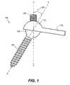
- FIG. 1is a side elevational view of a multi-axial screw assembly with a spherical landing surface
- FIG. 2Ais an exploded view of the multi-axial screw embodiment of FIG. 1 ;
- FIG. 2Bis an exploded cross-sectional view of the multi-axial screw embodiment of FIG. 1 ;
- FIG. 2Cis cross-sectional view of one embodiment of the spherical member 120 ;
- FIG. 2Dis a cross-sectional view of another embodiment of the spherical member 120 ;
- FIG. 3is a cross-sectional view of the multi-axial screw assembly of FIG. 1 with an attached elongated plate;
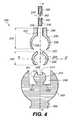
- FIG. 4is an exploded cross-sectional side view of another embodiment of a multi-axial screw with a spherical landing surface
- FIG. 5is a cross-sectional view of the multi-axial screw assembly of FIG. 4 with an attached elongated plate
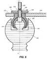
- FIG. 6is a cross-sectional view of another embodiment of the multi-axial screw assembly of FIG. 4 with an attached elongated plate.
- the inventionprovides a multi-axial screw with a spherical landing surface for receiving a plate stabilization element.
- a multi-axial screw 100 assemblyincludes a bone anchor 150 , a head 130 with a spherical outer surface and an extension member 160 .
- the multi-axial screw 100is designed to attach an elongated plate 170 with a semispherical end member 172 to a vertebral bone or any other bone.
- the bone anchor 150includes a body 155 with outer threads 154 and terminates in a spherical top end 110 and a sharp bottom end 152 .
- the spherical top end 110has a rough outer surface 112 and a bore 114 designed to receive a tool (not shown) for screwing the bone anchor 150 into the bone.
- the outer surface of the spherical top end 110includes serrations, knurling or horizontal elevations.
- the rough outer surface 112 , the serrations, knurling or horizontal elevationsprovide a good gripping surface.
- On top of the spherical top end 110sits a hollow spherical member 120 .
- Spherical member 120has a circular cross-section along the BB′ axis, shown in FIG. 2C .
- spherical member 120has a c-shaped cross-section along the BB′ axis, shown in FIG. 2D .
- Spherical member 120has an opening 122 and a spherical inner surface 126 that is configured to accommodate and grip the rough outer surface 112 of the spherical top end 110 .
- Inner surface 126can be rough or have serrations, horizontal elevations or knurling that can cooperate with the roughness, serrations, horizontal elevations or knurling of the outer surface 112 of the spherical top end 110 .
- Opening 122is provided so that a tool can be inserted through the opening 122 to reach the bore 114 of the spherical top end 110 for screwing the bone anchor 150 into the bone.
- the radius of the spherical member 120is slightly larger that the radius of the spherical top end 110 and slightly smaller than the radius of the head 130 so that it can be interference fitted between them.
- Head 130has a spherical outer surface 135 configured to provide a spherical landing surface for the end member 172 of the elongated plate 170 , shown in FIG. 3 and FIG. 1 .
- Head 130has an opening 132 that allows the above mentioned tool to reach the bore 114 of the spherical top end 110 for screwing the bone anchor 150 into the bone. Head 130 sits on top of the spherical member 120 and the inner surface 136 of the head 130 is interference fitted with the outer surface 128 of the spherical member 120 .
- the top portion of opening 132has inner threads 138 for receiving a locking member 140 .
- Locking member 140has a cylindrical shape and outer threads 142 that cooperate with the inner threads 138 of the head 130 thereby tightening head 130 to spherical member 120 and to spherical top end 110 .
- Locking member 140has a bore 144 on its top end for receiving a cylindrical appendage 162 of the removable extension member 160 . This configuration allows the extension member 160 to be positioned so that it always points in the vertical direction CC′ while the screw axis AA′ is oriented at an angle 102 away from the vertical CC′ axis, shown in FIG. 1 . Referring to FIG.
- semispherical end member 172 of the elongate plate 170has a through opening 174 that allows it to be placed over the locking member 140 .
- the bottom surface 176 of the semispherical end member 172sits on top of the spherical outer surface 135 of head 130 .
- End member 172can be rotated around axis AA′ while the extension member 160 always points in the vertical CC′ axis.
- Opening 174may also have inner threads that cooperate with the outer threads 142 of the locking member 140 .
- a retention nut 180is threaded around outer threads 164 of the extension member 160 and the outer threads 142 of the locking member 140 in order to tighten the end member 172 to the spherical outer surface 135 of the head 130 .
- the length 156 of the threaded body 155is in the range of 14 mm to 30 mm for screws used in cervical vertebrae and 35 mm to 50 mm for screws used in lumbar vertebrae. In other examples, length 156 is in the range of 10 mm to 60 mm.
- multi-axial screw assembly 100is made of titanium metal. In this configuration the head 130 may be rotated at any angle 102 relative to the screw axis AA′ and tighten down to the top end 110 via the locking member 140 .
- head 130is rotated so that the extension member 160 points in the vertical direction CC′ while the bone anchor 150 is placed at any other angle 102 relative to the vertical axis CC′.
- bone anchor 150is a screw.
- bone anchor 150may be a hook.
- extension member 160is an integral member of the locking member 140 and it can be broken off after the multi-axial screw assembly 100 is properly oriented and secured to the bone.
- assembly 200in another embodiment of a multi-axial screw assembly with a spherical landing surface, includes a bone anchor 250 having a spherical head 205 .
- Spherical head 205has a cylindrical bore opening 206 extending from the top surface 201 of spherical head 205 halfway into the center 202 of the spherical head 205 .
- From the bottom 203 of the bore opening 206extends a spherical top end 210 .
- Spherical top end 210has a rough outer surface 212 and a top bore opening 214 for receiving a tool (not shown) for screwing the bone anchor 250 into a bone.
- the outer surface 212 of the spherical top end 210includes serrations, knurling or horizontal elevations.
- the rough outer surface 212 , the serrations, knurling or horizontal elevationsprovide a good gripping surface.
- a spherical member 220On top of the spherical top end 210 sits a spherical member 220 .
- Spherical member 220has a circular cross-section along the BB′ axis, as shown in FIG. 2C .
- spherical member 220has a c-shaped cross-section along the BB′ axis, as shown in FIG. 2D .
- Spherical member 220has an opening 222 and a spherical inner surface 226 that is configured to accommodate and grip the rough outer surface 212 of the spherical top end 210 .
- Inner surface 226can be rough or have serrations, horizontal elevations or knurling that can cooperate with the roughness, serrations, horizontal elevations or knurling of the outer surface 212 of the spherical top end 210 .
- Opening 222is provided so that a tool can be inserted through the opening 222 to reach the bore 214 of the spherical top end 210 for screwing the bone anchor 250 into the bone.
- the radius of the spherical member 220is slightly larger that the radius of the spherical top end 210 and slightly smaller than the radius of crown 230 that sits on top of it so that it can be interference fitted between them.
- Crown 230has a spherical outer surface 235 and a cylindrical extension 236 .
- Crown 230has an opening 232 that allows the above mentioned tool to reach the bore 214 of the spherical top end 210 for screwing the bone anchor 250 into the bone.
- Crown 230sits on top of the spherical member 220 and the inner surface 238 of the crown 230 is interference fitted with the outer surface 228 of the spherical member 220 .
- the top portion of opening 232has inner threads 237 for receiving a locking member 240 .
- Locking member 240has a cylindrical shape and outer threads 242 that cooperate with the inner threads 237 of the crown 230 thereby tightening crown 230 to spherical member 220 and to spherical top end 210 .
- Locking member 240has a bore 244 on its top end for receiving a cylindrical appendage 262 of the removable extension member 260 . This configuration allows the extension member 260 to always point in the vertical direction CC′ while the screw axis AA′ is oriented at an angle 102 away from the vertical CC′ axis, as shown in FIG. 1 .
- planar end member 272 of the elongate plate 270has a through opening 274 that allows it to be placed over the cylindrical extension 236 of the crown 230 .
- the bottom surface 276 of the semispherical end member 272sits on top of the spherical outer surface 201 of spherical head 205 .
- End member 272can be rotated around axis AA′ while the extension member 260 always points in the vertical CC′ axis.
- Opening 274may also have inner threads that cooperate with outer threads 239 of the cylindrical extension 236 .
- a retention nut 280is threaded around outer threads 239 of the cylindrical extension 236 in order to tighten the end member 272 to the spherical outer surface 201 of the spherical head 205 .
- crown 230may be rotated at any angle 102 relative to the screw axis AA′ and tighten down to the top end 210 via the locking member 240 .
- crown 230is rotated so that the extension member 260 points in the vertical direction CC′ while the bone anchor 250 is placed at any other angle 102 relative to the vertical axis CC′.
- the retention nut 280is threaded around the locking member 240 and the inner threads 282 of nut 280 engage the outer threads 242 of the locking member 240 .
- nut 280counter sinks with a crater-type groove in the elongated plate 270 .
Landscapes
- Health & Medical Sciences (AREA)
- Orthopedic Medicine & Surgery (AREA)
- Life Sciences & Earth Sciences (AREA)
- Neurology (AREA)
- Surgery (AREA)
- Heart & Thoracic Surgery (AREA)
- Engineering & Computer Science (AREA)
- Biomedical Technology (AREA)
- Nuclear Medicine, Radiotherapy & Molecular Imaging (AREA)
- Medical Informatics (AREA)
- Molecular Biology (AREA)
- Animal Behavior & Ethology (AREA)
- General Health & Medical Sciences (AREA)
- Public Health (AREA)
- Veterinary Medicine (AREA)
- Surgical Instruments (AREA)
Abstract
Description
Claims (24)
Priority Applications (2)
| Application Number | Priority Date | Filing Date | Title |
|---|---|---|---|
| US11/156,435US7875060B2 (en) | 2003-09-24 | 2005-06-20 | Multi-axial screw with a spherical landing |
| PCT/US2005/021767WO2006012088A1 (en) | 2004-06-25 | 2005-06-21 | Multi-axial screw with a spherical landing |
Applications Claiming Priority (3)
| Application Number | Priority Date | Filing Date | Title |
|---|---|---|---|
| US10/669,927US7282064B2 (en) | 2003-02-11 | 2003-09-24 | Apparatus and method for connecting spinal vertebrae |
| US58289304P | 2004-06-25 | 2004-06-25 | |
| US11/156,435US7875060B2 (en) | 2003-09-24 | 2005-06-20 | Multi-axial screw with a spherical landing |
Related Parent Applications (1)
| Application Number | Title | Priority Date | Filing Date |
|---|---|---|---|
| US10/669,927Continuation-In-PartUS7282064B2 (en) | 2003-02-11 | 2003-09-24 | Apparatus and method for connecting spinal vertebrae |
Publications (2)
| Publication Number | Publication Date |
|---|---|
| US20050234454A1 US20050234454A1 (en) | 2005-10-20 |
| US7875060B2true US7875060B2 (en) | 2011-01-25 |
Family
ID=35097246
Family Applications (1)
| Application Number | Title | Priority Date | Filing Date |
|---|---|---|---|
| US11/156,435Expired - Fee RelatedUS7875060B2 (en) | 2003-09-24 | 2005-06-20 | Multi-axial screw with a spherical landing |
Country Status (2)
| Country | Link |
|---|---|
| US (1) | US7875060B2 (en) |
| WO (1) | WO2006012088A1 (en) |
Cited By (27)
| Publication number | Priority date | Publication date | Assignee | Title |
|---|---|---|---|---|
| US20080119857A1 (en)* | 2006-11-16 | 2008-05-22 | Spine Wave, Inc. | Multi-Axial Spinal Fixation System |
| US20100030224A1 (en)* | 2008-02-26 | 2010-02-04 | Spartek Medical, Inc. | Surgical tool and method for connecting a dynamic bone anchor and dynamic vertical rod |
| US20100030279A1 (en)* | 2008-02-26 | 2010-02-04 | Spartek Medical, Inc. | Load-sharing bone anchor having a deflectable post and axial spring and method for dynamic stabilization of the spine |
| US20100030274A1 (en)* | 2007-06-05 | 2010-02-04 | Spartek Medical, Inc. | Dynamic spinal rod and method for dynamic stabilization of the spine |
| US20100030270A1 (en)* | 2007-06-05 | 2010-02-04 | Spartek Medical, Inc. | Dynamic spinal rod assembly and method for dynamic stabilization of the spine |
| US20100030271A1 (en)* | 2008-02-26 | 2010-02-04 | Spartek Medical, Inc. | Modular in-line deflection rod and bone anchor system and method for dynamic stabilization of the spine |
| US20100030267A1 (en)* | 2007-06-05 | 2010-02-04 | Spartek Medical, Inc. | Surgical tool and method for implantation of a dynamic bone anchor |
| US20100036435A1 (en)* | 2008-02-26 | 2010-02-11 | Spartek Medical, Inc. | Load-sharing bone anchor having a deflectable post and method for dynamic stabilization of the spine |
| US20100036426A1 (en)* | 2008-02-26 | 2010-02-11 | Spartek Medical, Inc. | Versatile offset polyaxial connector and method for dynamic stabilization of the spine |
| US20100036436A1 (en)* | 2008-02-26 | 2010-02-11 | Spartek Medical, Inc. | Load-sharing bone anchor having a durable compliant member and method for dynamic stabilization of the spine |
| US20100036437A1 (en)* | 2008-02-26 | 2010-02-11 | Spartek Medical, Inc. | Load-sharing bone anchor having a deflectable post with a compliant ring and method for stabilization of the spine |
| US20100057140A1 (en)* | 2007-06-05 | 2010-03-04 | Spartek Medical, Inc. | Bone anchor for receiving a rod for stabilization and motion preservation spinal implantation system and method |
| US20100168795A1 (en)* | 2008-02-26 | 2010-07-01 | Spartek Medical, Inc. | Load-sharing bone anchor having a natural center of rotation and method for dynamic stabilization of the spine |
| US20110118783A1 (en)* | 2009-11-16 | 2011-05-19 | Spartek Medical, Inc. | Load-sharing bone anchor having a flexible post and method for dynamic stabilization of the spine |
| US8021396B2 (en) | 2007-06-05 | 2011-09-20 | Spartek Medical, Inc. | Configurable dynamic spinal rod and method for dynamic stabilization of the spine |
| US8057515B2 (en) | 2008-02-26 | 2011-11-15 | Spartek Medical, Inc. | Load-sharing anchor having a deflectable post and centering spring and method for dynamic stabilization of the spine |
| US8097024B2 (en) | 2008-02-26 | 2012-01-17 | Spartek Medical, Inc. | Load-sharing bone anchor having a deflectable post and method for stabilization of the spine |
| US8114134B2 (en) | 2007-06-05 | 2012-02-14 | Spartek Medical, Inc. | Spinal prosthesis having a three bar linkage for motion preservation and dynamic stabilization of the spine |
| US8257397B2 (en) | 2009-12-02 | 2012-09-04 | Spartek Medical, Inc. | Low profile spinal prosthesis incorporating a bone anchor having a deflectable post and a compound spinal rod |
| US8337536B2 (en) | 2008-02-26 | 2012-12-25 | Spartek Medical, Inc. | Load-sharing bone anchor having a deflectable post with a compliant ring and method for stabilization of the spine |
| US8430916B1 (en) | 2012-02-07 | 2013-04-30 | Spartek Medical, Inc. | Spinal rod connectors, methods of use, and spinal prosthesis incorporating spinal rod connectors |
| US8518085B2 (en) | 2010-06-10 | 2013-08-27 | Spartek Medical, Inc. | Adaptive spinal rod and methods for stabilization of the spine |
| US20140074169A1 (en)* | 2012-09-13 | 2014-03-13 | Warsaw Orthopedic, Inc. | Spinal correction system and method |
| US20140114358A1 (en)* | 2010-04-05 | 2014-04-24 | David L. Brumfield | Fully-Adjustable Bone Fixation Device |
| US20140142630A1 (en)* | 2011-07-25 | 2014-05-22 | Nedicrea International | Anchor member for vertebral osteosynthesis equipment |
| US10426521B2 (en)* | 2015-04-24 | 2019-10-01 | Medicrea International | Vertebral osteosynthesis equipment |
| US10893894B2 (en) | 2019-04-24 | 2021-01-19 | Aesculap Implant Systems, Llc | Transverse coupling for surgical implant extensions |
Families Citing this family (112)
| Publication number | Priority date | Publication date | Assignee | Title |
|---|---|---|---|---|
| US7833250B2 (en) | 2004-11-10 | 2010-11-16 | Jackson Roger P | Polyaxial bone screw with helically wound capture connection |
| US8377100B2 (en) | 2000-12-08 | 2013-02-19 | Roger P. Jackson | Closure for open-headed medical implant |
| US6726689B2 (en) | 2002-09-06 | 2004-04-27 | Roger P. Jackson | Helical interlocking mating guide and advancement structure |
| US10729469B2 (en) | 2006-01-09 | 2020-08-04 | Roger P. Jackson | Flexible spinal stabilization assembly with spacer having off-axis core member |
| US7862587B2 (en) | 2004-02-27 | 2011-01-04 | Jackson Roger P | Dynamic stabilization assemblies, tool set and method |
| US10258382B2 (en) | 2007-01-18 | 2019-04-16 | Roger P. Jackson | Rod-cord dynamic connection assemblies with slidable bone anchor attachment members along the cord |
| US8353932B2 (en) | 2005-09-30 | 2013-01-15 | Jackson Roger P | Polyaxial bone anchor assembly with one-piece closure, pressure insert and plastic elongate member |
| US8292926B2 (en) | 2005-09-30 | 2012-10-23 | Jackson Roger P | Dynamic stabilization connecting member with elastic core and outer sleeve |
| US8257402B2 (en) | 2002-09-06 | 2012-09-04 | Jackson Roger P | Closure for rod receiving orthopedic implant having left handed thread removal |
| US8876868B2 (en) | 2002-09-06 | 2014-11-04 | Roger P. Jackson | Helical guide and advancement flange with radially loaded lip |
| US8282673B2 (en) | 2002-09-06 | 2012-10-09 | Jackson Roger P | Anti-splay medical implant closure with multi-surface removal aperture |
| WO2006052796A2 (en) | 2004-11-10 | 2006-05-18 | Jackson Roger P | Helical guide and advancement flange with break-off extensions |
| US7621918B2 (en) | 2004-11-23 | 2009-11-24 | Jackson Roger P | Spinal fixation tool set and method |
| US6716214B1 (en) | 2003-06-18 | 2004-04-06 | Roger P. Jackson | Polyaxial bone screw with spline capture connection |
| US8540753B2 (en) | 2003-04-09 | 2013-09-24 | Roger P. Jackson | Polyaxial bone screw with uploaded threaded shank and method of assembly and use |
| US7377923B2 (en) | 2003-05-22 | 2008-05-27 | Alphatec Spine, Inc. | Variable angle spinal screw assembly |
| US7776067B2 (en) | 2005-05-27 | 2010-08-17 | Jackson Roger P | Polyaxial bone screw with shank articulation pressure insert and method |
| US7766915B2 (en) | 2004-02-27 | 2010-08-03 | Jackson Roger P | Dynamic fixation assemblies with inner core and outer coil-like member |
| US8398682B2 (en) | 2003-06-18 | 2013-03-19 | Roger P. Jackson | Polyaxial bone screw assembly |
| US8092500B2 (en) | 2007-05-01 | 2012-01-10 | Jackson Roger P | Dynamic stabilization connecting member with floating core, compression spacer and over-mold |
| US8257398B2 (en) | 2003-06-18 | 2012-09-04 | Jackson Roger P | Polyaxial bone screw with cam capture |
| US7967850B2 (en) | 2003-06-18 | 2011-06-28 | Jackson Roger P | Polyaxial bone anchor with helical capture connection, insert and dual locking assembly |
| US8137386B2 (en) | 2003-08-28 | 2012-03-20 | Jackson Roger P | Polyaxial bone screw apparatus |
| US8366753B2 (en) | 2003-06-18 | 2013-02-05 | Jackson Roger P | Polyaxial bone screw assembly with fixed retaining structure |
| US8926670B2 (en) | 2003-06-18 | 2015-01-06 | Roger P. Jackson | Polyaxial bone screw assembly |
| US8377102B2 (en) | 2003-06-18 | 2013-02-19 | Roger P. Jackson | Polyaxial bone anchor with spline capture connection and lower pressure insert |
| US7179261B2 (en) | 2003-12-16 | 2007-02-20 | Depuy Spine, Inc. | Percutaneous access devices and bone anchor assemblies |
| US7527638B2 (en) | 2003-12-16 | 2009-05-05 | Depuy Spine, Inc. | Methods and devices for minimally invasive spinal fixation element placement |
| US11419642B2 (en) | 2003-12-16 | 2022-08-23 | Medos International Sarl | Percutaneous access devices and bone anchor assemblies |
| US7993373B2 (en)* | 2005-02-22 | 2011-08-09 | Hoy Robert W | Polyaxial orthopedic fastening apparatus |
| JP2007525274A (en) | 2004-02-27 | 2007-09-06 | ロジャー・ピー・ジャクソン | Orthopedic implant rod reduction instrument set and method |
| US8152810B2 (en) | 2004-11-23 | 2012-04-10 | Jackson Roger P | Spinal fixation tool set and method |
| US7160300B2 (en) | 2004-02-27 | 2007-01-09 | Jackson Roger P | Orthopedic implant rod reduction tool set and method |
| US11241261B2 (en) | 2005-09-30 | 2022-02-08 | Roger P Jackson | Apparatus and method for soft spinal stabilization using a tensionable cord and releasable end structure |
| US8114086B2 (en) | 2004-03-08 | 2012-02-14 | Zimmer Technology, Inc. | Navigated cut guide locator |
| US7993341B2 (en) | 2004-03-08 | 2011-08-09 | Zimmer Technology, Inc. | Navigated orthopaedic guide and method |
| JP4980881B2 (en)* | 2004-03-26 | 2012-07-18 | ジンテーズ ゲゼルシャフト ミト ベシュレンクテル ハフツング | Bone screw with joint |
| US7651502B2 (en) | 2004-09-24 | 2010-01-26 | Jackson Roger P | Spinal fixation tool set and method for rod reduction and fastener insertion |
| US8926672B2 (en) | 2004-11-10 | 2015-01-06 | Roger P. Jackson | Splay control closure for open bone anchor |
| US7875065B2 (en) | 2004-11-23 | 2011-01-25 | Jackson Roger P | Polyaxial bone screw with multi-part shank retainer and pressure insert |
| US9168069B2 (en) | 2009-06-15 | 2015-10-27 | Roger P. Jackson | Polyaxial bone anchor with pop-on shank and winged insert with lower skirt for engaging a friction fit retainer |
| US9216041B2 (en) | 2009-06-15 | 2015-12-22 | Roger P. Jackson | Spinal connecting members with tensioned cords and rigid sleeves for engaging compression inserts |
| US9980753B2 (en) | 2009-06-15 | 2018-05-29 | Roger P Jackson | pivotal anchor with snap-in-place insert having rotation blocking extensions |
| WO2006057837A1 (en) | 2004-11-23 | 2006-06-01 | Jackson Roger P | Spinal fixation tool attachment structure |
| US8444681B2 (en) | 2009-06-15 | 2013-05-21 | Roger P. Jackson | Polyaxial bone anchor with pop-on shank, friction fit retainer and winged insert |
| US8308782B2 (en) | 2004-11-23 | 2012-11-13 | Jackson Roger P | Bone anchors with longitudinal connecting member engaging inserts and closures for fixation and optional angulation |
| WO2006058221A2 (en) | 2004-11-24 | 2006-06-01 | Abdou Samy M | Devices and methods for inter-vertebral orthopedic device placement |
| US7901437B2 (en) | 2007-01-26 | 2011-03-08 | Jackson Roger P | Dynamic stabilization member with molded connection |
| US10076361B2 (en) | 2005-02-22 | 2018-09-18 | Roger P. Jackson | Polyaxial bone screw with spherical capture, compression and alignment and retention structures |
| US7828828B2 (en)* | 2005-04-14 | 2010-11-09 | Warsaw Orthopedic, Inc | Intervertebral joint |
| US7766943B1 (en)* | 2005-08-11 | 2010-08-03 | Medicine Lodge Inc. | Modular percutaneous spinal fusion system and method |
| US8105368B2 (en) | 2005-09-30 | 2012-01-31 | Jackson Roger P | Dynamic stabilization connecting member with slitted core and outer sleeve |
| US7704271B2 (en) | 2005-12-19 | 2010-04-27 | Abdou M Samy | Devices and methods for inter-vertebral orthopedic device placement |
| US7520880B2 (en) | 2006-01-09 | 2009-04-21 | Zimmer Technology, Inc. | Adjustable surgical support base with integral hinge |
| US7744600B2 (en) | 2006-01-10 | 2010-06-29 | Zimmer Technology, Inc. | Bone resection guide and method |
| US20080058808A1 (en) | 2006-06-14 | 2008-03-06 | Spartek Medical, Inc. | Implant system and method to treat degenerative disorders of the spine |
| CA2670988C (en) | 2006-12-08 | 2014-03-25 | Roger P. Jackson | Tool system for dynamic spinal implants |
| US8366745B2 (en) | 2007-05-01 | 2013-02-05 | Jackson Roger P | Dynamic stabilization assembly having pre-compressed spacers with differential displacements |
| US8475498B2 (en) | 2007-01-18 | 2013-07-02 | Roger P. Jackson | Dynamic stabilization connecting member with cord connection |
| US10792074B2 (en) | 2007-01-22 | 2020-10-06 | Roger P. Jackson | Pivotal bone anchor assemly with twist-in-place friction fit insert |
| US8012177B2 (en) | 2007-02-12 | 2011-09-06 | Jackson Roger P | Dynamic stabilization assembly with frusto-conical connection |
| US8979904B2 (en) | 2007-05-01 | 2015-03-17 | Roger P Jackson | Connecting member with tensioned cord, low profile rigid sleeve and spacer with torsion control |
| US10383660B2 (en) | 2007-05-01 | 2019-08-20 | Roger P. Jackson | Soft stabilization assemblies with pretensioned cords |
| US7942911B2 (en) | 2007-05-16 | 2011-05-17 | Ortho Innovations, Llc | Polyaxial bone screw |
| US7942909B2 (en) | 2009-08-13 | 2011-05-17 | Ortho Innovations, Llc | Thread-thru polyaxial pedicle screw system |
| US7947065B2 (en) | 2008-11-14 | 2011-05-24 | Ortho Innovations, Llc | Locking polyaxial ball and socket fastener |
| US8197518B2 (en) | 2007-05-16 | 2012-06-12 | Ortho Innovations, Llc | Thread-thru polyaxial pedicle screw system |
| US7951173B2 (en) | 2007-05-16 | 2011-05-31 | Ortho Innovations, Llc | Pedicle screw implant system |
| US7942910B2 (en) | 2007-05-16 | 2011-05-17 | Ortho Innovations, Llc | Polyaxial bone screw |
| CA2690038C (en) | 2007-05-31 | 2012-11-27 | Roger P. Jackson | Dynamic stabilization connecting member with pre-tensioned solid core |
| US8109970B2 (en) | 2007-06-05 | 2012-02-07 | Spartek Medical, Inc. | Deflection rod system with a deflection contouring shield for a spine implant and method |
| US8052722B2 (en) | 2007-06-05 | 2011-11-08 | Spartek Medical, Inc. | Dual deflection rod system for a dynamic stabilization and motion preservation spinal implantation system and method |
| US8911477B2 (en) | 2007-10-23 | 2014-12-16 | Roger P. Jackson | Dynamic stabilization member with end plate support and cable core extension |
| US9017384B2 (en)* | 2008-05-13 | 2015-04-28 | Stryker Spine | Composite spinal rod |
| US8425514B2 (en)* | 2008-06-25 | 2013-04-23 | Westmark Medical, Llc. | Spinal fixation device |
| AU2010260521C1 (en) | 2008-08-01 | 2013-08-01 | Roger P. Jackson | Longitudinal connecting member with sleeved tensioned cords |
| EP2328496A4 (en)* | 2008-09-26 | 2013-07-03 | Spartek Medical Inc | Load-sharing bone anchor, dynamic vertical rod and assemblies for dynamic stabilization of the spine |
| US8075603B2 (en) | 2008-11-14 | 2011-12-13 | Ortho Innovations, Llc | Locking polyaxial ball and socket fastener |
| CN103826560A (en) | 2009-06-15 | 2014-05-28 | 罗杰.P.杰克逊 | Polyaxial Bone Anchor with Socket Stem and Winged Inserts with Friction Fit Compression Collars |
| US9668771B2 (en) | 2009-06-15 | 2017-06-06 | Roger P Jackson | Soft stabilization assemblies with off-set connector |
| US8998959B2 (en) | 2009-06-15 | 2015-04-07 | Roger P Jackson | Polyaxial bone anchors with pop-on shank, fully constrained friction fit retainer and lock and release insert |
| US11229457B2 (en) | 2009-06-15 | 2022-01-25 | Roger P. Jackson | Pivotal bone anchor assembly with insert tool deployment |
| US8986353B2 (en) | 2009-07-09 | 2015-03-24 | Orthohelix Surgical Designs, Inc. | Osteotomy plate, plate driver and method for their use |
| EP2485654B1 (en) | 2009-10-05 | 2021-05-05 | Jackson P. Roger | Polyaxial bone anchor with non-pivotable retainer and pop-on shank, some with friction fit |
| US8764806B2 (en) | 2009-12-07 | 2014-07-01 | Samy Abdou | Devices and methods for minimally invasive spinal stabilization and instrumentation |
| US12383311B2 (en) | 2010-05-14 | 2025-08-12 | Roger P. Jackson | Pivotal bone anchor assembly and method for use thereof |
| WO2012030712A1 (en) | 2010-08-30 | 2012-03-08 | Zimmer Spine, Inc. | Polyaxial pedicle screw |
| AU2011299558A1 (en) | 2010-09-08 | 2013-05-02 | Roger P. Jackson | Dynamic stabilization members with elastic and inelastic sections |
| AU2011324058A1 (en) | 2010-11-02 | 2013-06-20 | Roger P. Jackson | Polyaxial bone anchor with pop-on shank and pivotable retainer |
| JP5865479B2 (en) | 2011-03-24 | 2016-02-17 | ロジャー・ピー・ジャクソン | Multiaxial bone anchor with compound joint and pop-mounted shank |
| US8845728B1 (en) | 2011-09-23 | 2014-09-30 | Samy Abdou | Spinal fixation devices and methods of use |
| US8911479B2 (en) | 2012-01-10 | 2014-12-16 | Roger P. Jackson | Multi-start closures for open implants |
| US20130226240A1 (en) | 2012-02-22 | 2013-08-29 | Samy Abdou | Spinous process fixation devices and methods of use |
| US9198767B2 (en) | 2012-08-28 | 2015-12-01 | Samy Abdou | Devices and methods for spinal stabilization and instrumentation |
| US9320617B2 (en) | 2012-10-22 | 2016-04-26 | Cogent Spine, LLC | Devices and methods for spinal stabilization and instrumentation |
| EP2911599B1 (en)* | 2012-10-23 | 2020-04-29 | Nexus Spine, L.L.C. | Surgical construct coupling system |
| US8911478B2 (en) | 2012-11-21 | 2014-12-16 | Roger P. Jackson | Splay control closure for open bone anchor |
| US10058354B2 (en) | 2013-01-28 | 2018-08-28 | Roger P. Jackson | Pivotal bone anchor assembly with frictional shank head seating surfaces |
| US8852239B2 (en) | 2013-02-15 | 2014-10-07 | Roger P Jackson | Sagittal angle screw with integral shank and receiver |
| FR3004636A1 (en)* | 2013-04-19 | 2014-10-24 | Medicrea International | RECOVERY ASSEMBLY FOR VERTEBRAL OSTEOSYNTHESIS EQUIPMENT |
| US9453526B2 (en) | 2013-04-30 | 2016-09-27 | Degen Medical, Inc. | Bottom-loading anchor assembly |
| US9566092B2 (en) | 2013-10-29 | 2017-02-14 | Roger P. Jackson | Cervical bone anchor with collet retainer and outer locking sleeve |
| US9717533B2 (en) | 2013-12-12 | 2017-08-01 | Roger P. Jackson | Bone anchor closure pivot-splay control flange form guide and advancement structure |
| US9451993B2 (en) | 2014-01-09 | 2016-09-27 | Roger P. Jackson | Bi-radial pop-on cervical bone anchor |
| US10064658B2 (en) | 2014-06-04 | 2018-09-04 | Roger P. Jackson | Polyaxial bone anchor with insert guides |
| US9597119B2 (en) | 2014-06-04 | 2017-03-21 | Roger P. Jackson | Polyaxial bone anchor with polymer sleeve |
| US10857003B1 (en) | 2015-10-14 | 2020-12-08 | Samy Abdou | Devices and methods for vertebral stabilization |
| US10695107B2 (en)* | 2015-12-03 | 2020-06-30 | Warsaw Orthopedic, Inc. | Spinal implant system and methods of use |
| US10744000B1 (en) | 2016-10-25 | 2020-08-18 | Samy Abdou | Devices and methods for vertebral bone realignment |
| US10973648B1 (en) | 2016-10-25 | 2021-04-13 | Samy Abdou | Devices and methods for vertebral bone realignment |
| CN108670399A (en)* | 2018-06-13 | 2018-10-19 | 迪恩医疗科技有限公司 | The universal unidirectional unification pedicle of vertebral arch screw of vertebral column minimally invasive nails on nail system |
| US11179248B2 (en) | 2018-10-02 | 2021-11-23 | Samy Abdou | Devices and methods for spinal implantation |
Citations (10)
| Publication number | Priority date | Publication date | Assignee | Title |
|---|---|---|---|---|
| US5591166A (en)* | 1995-03-27 | 1997-01-07 | Smith & Nephew Richards, Inc. | Multi angle bone bolt |
| US5725528A (en)* | 1997-02-12 | 1998-03-10 | Third Millennium Engineering, Llc | Modular polyaxial locking pedicle screw |
| US5885286A (en)* | 1996-09-24 | 1999-03-23 | Sdgi Holdings, Inc. | Multi-axial bone screw assembly |
| US6106526A (en)* | 1995-03-15 | 2000-08-22 | Harms; Juergen | Member for stabilizing cervical vertebrae |
| US6267765B1 (en)* | 1997-06-03 | 2001-07-31 | Jean Taylor | Multidirectional adaptable vertebral osteosyntsis device with reduced space requirement |
| US6290703B1 (en)* | 1996-05-13 | 2001-09-18 | Stryker France S.A. | Device for fixing the sacral bone to adjacent vertebrae during osteosynthesis of the backbone |
| US20030073996A1 (en)* | 2001-10-17 | 2003-04-17 | Doubler Robert L. | Split ring bone screw for a spinal fixation system |
| US20030153911A1 (en)* | 2002-02-13 | 2003-08-14 | Endius Incorporated | Apparatus for connecting a longitudinal member to a bone portion |
| US20030216735A1 (en)* | 2002-05-15 | 2003-11-20 | Moti Altarac | Variable locking spinal screw having a knurled collar |
| US7335201B2 (en)* | 2003-09-26 | 2008-02-26 | Zimmer Spine, Inc. | Polyaxial bone screw with torqueless fastening |
Family Cites Families (2)
| Publication number | Priority date | Publication date | Assignee | Title |
|---|---|---|---|---|
| US5879350A (en)* | 1996-09-24 | 1999-03-09 | Sdgi Holdings, Inc. | Multi-axial bone screw assembly |
| US6280442B1 (en)* | 1999-09-01 | 2001-08-28 | Sdgi Holdings, Inc. | Multi-axial bone screw assembly |
- 2005
- 2005-06-20USUS11/156,435patent/US7875060B2/ennot_activeExpired - Fee Related
- 2005-06-21WOPCT/US2005/021767patent/WO2006012088A1/enactiveApplication Filing
Patent Citations (11)
| Publication number | Priority date | Publication date | Assignee | Title |
|---|---|---|---|---|
| US6106526A (en)* | 1995-03-15 | 2000-08-22 | Harms; Juergen | Member for stabilizing cervical vertebrae |
| US5591166A (en)* | 1995-03-27 | 1997-01-07 | Smith & Nephew Richards, Inc. | Multi angle bone bolt |
| US6290703B1 (en)* | 1996-05-13 | 2001-09-18 | Stryker France S.A. | Device for fixing the sacral bone to adjacent vertebrae during osteosynthesis of the backbone |
| US5885286A (en)* | 1996-09-24 | 1999-03-23 | Sdgi Holdings, Inc. | Multi-axial bone screw assembly |
| US5725528A (en)* | 1997-02-12 | 1998-03-10 | Third Millennium Engineering, Llc | Modular polyaxial locking pedicle screw |
| US6267765B1 (en)* | 1997-06-03 | 2001-07-31 | Jean Taylor | Multidirectional adaptable vertebral osteosyntsis device with reduced space requirement |
| US20030073996A1 (en)* | 2001-10-17 | 2003-04-17 | Doubler Robert L. | Split ring bone screw for a spinal fixation system |
| US20030153911A1 (en)* | 2002-02-13 | 2003-08-14 | Endius Incorporated | Apparatus for connecting a longitudinal member to a bone portion |
| US20030216735A1 (en)* | 2002-05-15 | 2003-11-20 | Moti Altarac | Variable locking spinal screw having a knurled collar |
| US6733502B2 (en)* | 2002-05-15 | 2004-05-11 | Cross Medical Products, Inc. | Variable locking spinal screw having a knurled collar |
| US7335201B2 (en)* | 2003-09-26 | 2008-02-26 | Zimmer Spine, Inc. | Polyaxial bone screw with torqueless fastening |
Non-Patent Citations (1)
| Title |
|---|
| http://wordnet.princeton.edu/perl/webwn?s=plate.* |
Cited By (51)
| Publication number | Priority date | Publication date | Assignee | Title |
|---|---|---|---|---|
| US8162990B2 (en) | 2006-11-16 | 2012-04-24 | Spine Wave, Inc. | Multi-axial spinal fixation system |
| US10448975B2 (en) | 2006-11-16 | 2019-10-22 | Spine Wave, Inc. | Multi-axial spinal fixation system |
| US9861395B2 (en) | 2006-11-16 | 2018-01-09 | Spine Wave, Inc. | Multi-axial spinal fixation system |
| US20080119857A1 (en)* | 2006-11-16 | 2008-05-22 | Spine Wave, Inc. | Multi-Axial Spinal Fixation System |
| US20100030270A1 (en)* | 2007-06-05 | 2010-02-04 | Spartek Medical, Inc. | Dynamic spinal rod assembly and method for dynamic stabilization of the spine |
| US8568451B2 (en) | 2007-06-05 | 2013-10-29 | Spartek Medical, Inc. | Bone anchor for receiving a rod for stabilization and motion preservation spinal implantation system and method |
| US20100030267A1 (en)* | 2007-06-05 | 2010-02-04 | Spartek Medical, Inc. | Surgical tool and method for implantation of a dynamic bone anchor |
| US8317836B2 (en) | 2007-06-05 | 2012-11-27 | Spartek Medical, Inc. | Bone anchor for receiving a rod for stabilization and motion preservation spinal implantation system and method |
| US8021396B2 (en) | 2007-06-05 | 2011-09-20 | Spartek Medical, Inc. | Configurable dynamic spinal rod and method for dynamic stabilization of the spine |
| US8114134B2 (en) | 2007-06-05 | 2012-02-14 | Spartek Medical, Inc. | Spinal prosthesis having a three bar linkage for motion preservation and dynamic stabilization of the spine |
| US8092501B2 (en) | 2007-06-05 | 2012-01-10 | Spartek Medical, Inc. | Dynamic spinal rod and method for dynamic stabilization of the spine |
| US8083772B2 (en) | 2007-06-05 | 2011-12-27 | Spartek Medical, Inc. | Dynamic spinal rod assembly and method for dynamic stabilization of the spine |
| US20100057140A1 (en)* | 2007-06-05 | 2010-03-04 | Spartek Medical, Inc. | Bone anchor for receiving a rod for stabilization and motion preservation spinal implantation system and method |
| US20100057139A1 (en)* | 2007-06-05 | 2010-03-04 | Spartek Medical, Inc. | Bone anchor for receiving a rod for stabilization and motion preservation spinal implantation system and method |
| US20100030274A1 (en)* | 2007-06-05 | 2010-02-04 | Spartek Medical, Inc. | Dynamic spinal rod and method for dynamic stabilization of the spine |
| US8048115B2 (en) | 2007-06-05 | 2011-11-01 | Spartek Medical, Inc. | Surgical tool and method for implantation of a dynamic bone anchor |
| US8057517B2 (en) | 2008-02-26 | 2011-11-15 | Spartek Medical, Inc. | Load-sharing component having a deflectable post and centering spring and method for dynamic stabilization of the spine |
| US8267979B2 (en) | 2008-02-26 | 2012-09-18 | Spartek Medical, Inc. | Load-sharing bone anchor having a deflectable post and axial spring and method for dynamic stabilization of the spine |
| US8016861B2 (en) | 2008-02-26 | 2011-09-13 | Spartek Medical, Inc. | Versatile polyaxial connector assembly and method for dynamic stabilization of the spine |
| US8007518B2 (en) | 2008-02-26 | 2011-08-30 | Spartek Medical, Inc. | Load-sharing component having a deflectable post and method for dynamic stabilization of the spine |
| US20100030224A1 (en)* | 2008-02-26 | 2010-02-04 | Spartek Medical, Inc. | Surgical tool and method for connecting a dynamic bone anchor and dynamic vertical rod |
| US8048125B2 (en) | 2008-02-26 | 2011-11-01 | Spartek Medical, Inc. | Versatile offset polyaxial connector and method for dynamic stabilization of the spine |
| US8057515B2 (en) | 2008-02-26 | 2011-11-15 | Spartek Medical, Inc. | Load-sharing anchor having a deflectable post and centering spring and method for dynamic stabilization of the spine |
| US20100168795A1 (en)* | 2008-02-26 | 2010-07-01 | Spartek Medical, Inc. | Load-sharing bone anchor having a natural center of rotation and method for dynamic stabilization of the spine |
| US20100036421A1 (en)* | 2008-02-26 | 2010-02-11 | Spartek Medical, Inc. | Load-sharing component having a deflectable post and method for dynamic stabilization of the spine |
| US8083775B2 (en) | 2008-02-26 | 2011-12-27 | Spartek Medical, Inc. | Load-sharing bone anchor having a natural center of rotation and method for dynamic stabilization of the spine |
| US20100036437A1 (en)* | 2008-02-26 | 2010-02-11 | Spartek Medical, Inc. | Load-sharing bone anchor having a deflectable post with a compliant ring and method for stabilization of the spine |
| US8097024B2 (en) | 2008-02-26 | 2012-01-17 | Spartek Medical, Inc. | Load-sharing bone anchor having a deflectable post and method for stabilization of the spine |
| US20100036436A1 (en)* | 2008-02-26 | 2010-02-11 | Spartek Medical, Inc. | Load-sharing bone anchor having a durable compliant member and method for dynamic stabilization of the spine |
| US20100036426A1 (en)* | 2008-02-26 | 2010-02-11 | Spartek Medical, Inc. | Versatile offset polyaxial connector and method for dynamic stabilization of the spine |
| US8211155B2 (en) | 2008-02-26 | 2012-07-03 | Spartek Medical, Inc. | Load-sharing bone anchor having a durable compliant member and method for dynamic stabilization of the spine |
| US20100030279A1 (en)* | 2008-02-26 | 2010-02-04 | Spartek Medical, Inc. | Load-sharing bone anchor having a deflectable post and axial spring and method for dynamic stabilization of the spine |
| US20100030271A1 (en)* | 2008-02-26 | 2010-02-04 | Spartek Medical, Inc. | Modular in-line deflection rod and bone anchor system and method for dynamic stabilization of the spine |
| US8012181B2 (en) | 2008-02-26 | 2011-09-06 | Spartek Medical, Inc. | Modular in-line deflection rod and bone anchor system and method for dynamic stabilization of the spine |
| US20100036435A1 (en)* | 2008-02-26 | 2010-02-11 | Spartek Medical, Inc. | Load-sharing bone anchor having a deflectable post and method for dynamic stabilization of the spine |
| US8333792B2 (en) | 2008-02-26 | 2012-12-18 | Spartek Medical, Inc. | Load-sharing bone anchor having a deflectable post and method for dynamic stabilization of the spine |
| US8337536B2 (en) | 2008-02-26 | 2012-12-25 | Spartek Medical, Inc. | Load-sharing bone anchor having a deflectable post with a compliant ring and method for stabilization of the spine |
| US8216281B2 (en) | 2008-12-03 | 2012-07-10 | Spartek Medical, Inc. | Low profile spinal prosthesis incorporating a bone anchor having a deflectable post and a compound spinal rod |
| US20110118783A1 (en)* | 2009-11-16 | 2011-05-19 | Spartek Medical, Inc. | Load-sharing bone anchor having a flexible post and method for dynamic stabilization of the spine |
| US8372122B2 (en) | 2009-12-02 | 2013-02-12 | Spartek Medical, Inc. | Low profile spinal prosthesis incorporating a bone anchor having a deflectable post and a compound spinal rod |
| US8394127B2 (en) | 2009-12-02 | 2013-03-12 | Spartek Medical, Inc. | Low profile spinal prosthesis incorporating a bone anchor having a deflectable post and a compound spinal rod |
| US8257397B2 (en) | 2009-12-02 | 2012-09-04 | Spartek Medical, Inc. | Low profile spinal prosthesis incorporating a bone anchor having a deflectable post and a compound spinal rod |
| US20140114358A1 (en)* | 2010-04-05 | 2014-04-24 | David L. Brumfield | Fully-Adjustable Bone Fixation Device |
| US8518085B2 (en) | 2010-06-10 | 2013-08-27 | Spartek Medical, Inc. | Adaptive spinal rod and methods for stabilization of the spine |
| US20140142630A1 (en)* | 2011-07-25 | 2014-05-22 | Nedicrea International | Anchor member for vertebral osteosynthesis equipment |
| US9192412B2 (en)* | 2011-07-25 | 2015-11-24 | Medicrea International | Anchor member for vertebral osteosynthesis equipment |
| US8430916B1 (en) | 2012-02-07 | 2013-04-30 | Spartek Medical, Inc. | Spinal rod connectors, methods of use, and spinal prosthesis incorporating spinal rod connectors |
| US20140074169A1 (en)* | 2012-09-13 | 2014-03-13 | Warsaw Orthopedic, Inc. | Spinal correction system and method |
| US10426521B2 (en)* | 2015-04-24 | 2019-10-01 | Medicrea International | Vertebral osteosynthesis equipment |
| US10893894B2 (en) | 2019-04-24 | 2021-01-19 | Aesculap Implant Systems, Llc | Transverse coupling for surgical implant extensions |
| US11571246B2 (en) | 2019-04-24 | 2023-02-07 | Aesculap Implant Systems, Llc | Transverse coupling for surgical implant extensions |
Also Published As
| Publication number | Publication date |
|---|---|
| WO2006012088A1 (en) | 2006-02-02 |
| US20050234454A1 (en) | 2005-10-20 |
Similar Documents
| Publication | Publication Date | Title |
|---|---|---|
| US7875060B2 (en) | Multi-axial screw with a spherical landing | |
| US11925396B2 (en) | Locking element for a polyaxial bone anchor, bone plate assembly and tool | |
| US9936981B2 (en) | Anchor device for anchoring an elongated rod to the spine | |
| US6106526A (en) | Member for stabilizing cervical vertebrae | |
| US6709434B1 (en) | Spinal osteosynthesis device | |
| US6280445B1 (en) | Multi-axial bone anchor system | |
| JP4318421B2 (en) | Multiaxial bone screw assembly | |
| US7682379B2 (en) | Device for osteosynthesis | |
| CA2376030C (en) | Bone screw with axially two-part screw head | |
| US6077262A (en) | Posterior spinal implant | |
| US5545165A (en) | Anchoring member | |
| US20030036758A1 (en) | Angle-adjustable bone screw and device for osteosynthetic bone fixation | |
| US20080086132A1 (en) | Bone anchoring device | |
| US20050080415A1 (en) | Polyaxial bone anchor and method of spinal fixation | |
| US20090204155A1 (en) | Polyaxial bone anchor with headless pedicle screw | |
| US20100249846A1 (en) | Variable height, multi-axial bone screw assembly | |
| US20060235385A1 (en) | Low profile polyaxial screw | |
| KR20080040684A (en) | Bipolar corrugated screw assembly | |
| US20190038319A1 (en) | Stabilization device for bones or vertebrae | |
| US8672983B2 (en) | Orthopedic plate system | |
| KR101166614B1 (en) | Orthopedic plate system | |
| ZA200109471B (en) | Angle-adjustable bone screw and device for the osteosynthetic bone fixation. |
Legal Events
| Date | Code | Title | Description |
|---|---|---|---|
| AS | Assignment | Owner name:SPINEFRONTLER, L.L.S., PENNSYLVANIA Free format text:ASSIGNMENT OF ASSIGNORS INTEREST;ASSIGNOR:CHIN, KINGSLEY R.;REEL/FRAME:018262/0582 Effective date:20060828 | |
| STCF | Information on status: patent grant | Free format text:PATENTED CASE | |
| FPAY | Fee payment | Year of fee payment:4 | |
| SULP | Surcharge for late payment | ||
| FEPP | Fee payment procedure | Free format text:MAINTENANCE FEE REMINDER MAILED (ORIGINAL EVENT CODE: REM.); ENTITY STATUS OF PATENT OWNER: SMALL ENTITY | |
| FEPP | Fee payment procedure | Free format text:7.5 YR SURCHARGE - LATE PMT W/IN 6 MO, SMALL ENTITY (ORIGINAL EVENT CODE: M2555); ENTITY STATUS OF PATENT OWNER: SMALL ENTITY | |
| MAFP | Maintenance fee payment | Free format text:PAYMENT OF MAINTENANCE FEE, 8TH YR, SMALL ENTITY (ORIGINAL EVENT CODE: M2552); ENTITY STATUS OF PATENT OWNER: SMALL ENTITY Year of fee payment:8 | |
| AS | Assignment | Owner name:KIC VENTURES, LLC, MASSACHUSETTS Free format text:ASSIGNMENT OF ASSIGNORS INTEREST;ASSIGNOR:SPINEFRONTIER, INC;REEL/FRAME:053972/0737 Effective date:20190701 | |
| AS | Assignment | Owner name:KIC VENTURES, LLC, MASSACHUSETTS Free format text:ASSIGNMENT OF ASSIGNORS INTEREST;ASSIGNOR:SPINEFRONTIER, LLS;REEL/FRAME:054027/0319 Effective date:20190701 | |
| FEPP | Fee payment procedure | Free format text:MAINTENANCE FEE REMINDER MAILED (ORIGINAL EVENT CODE: REM.); ENTITY STATUS OF PATENT OWNER: SMALL ENTITY | |
| LAPS | Lapse for failure to pay maintenance fees | Free format text:PATENT EXPIRED FOR FAILURE TO PAY MAINTENANCE FEES (ORIGINAL EVENT CODE: EXP.); ENTITY STATUS OF PATENT OWNER: SMALL ENTITY | |
| STCH | Information on status: patent discontinuation | Free format text:PATENT EXPIRED DUE TO NONPAYMENT OF MAINTENANCE FEES UNDER 37 CFR 1.362 | |
| FP | Lapsed due to failure to pay maintenance fee | Effective date:20230125 |